Embed Size (px)
Citation preview
A7202
Preliminary UHF ASK/OOK Receiver
Nov. 2008, Version 0.4 (Preliminary) AMIC Communication Corporation 1
Document Title
A7202 Data Sheet
Revision History
Rev. No. History Issue Date Remark
0.0 Initial issue 2007/11/26
0.1 Modify application circuit 2008/2/27
0.2 Add top marking info., reflow profile, Carry tape & reel dimensions. Add A7202B hardware control mode description
2008/9/28
0.3 Modify Top Marking Information, package type. 2008/10/8
0.4 Modify ordering information 2008/11/4
Important Notice:
AMICCOM reserves the right to make changes to its products or to discontinue any integrated circuit product or service without notice. AMICCOM integrated circuit products are not designed, intended, authorized, or warranted to be suitable for use in life-support applications, devices or systems or other critical applications. Use of AMICCOM products in such applications is understood to be fully at the risk of the customer.
A7202
Preliminary UHF ASK/OOK Receiver
Nov. 2008, Version 0.4 (Preliminary) AMIC Communication Corporation 2
Table of Content
1. General Description ..................................................................................................................................................................3 2. Typical Applications ..................................................................................................................................................................3 3. Features....................................................................................................................................................................................3 4. Pin Configuration ......................................................................................................................................................................3 5. Pin Description..........................................................................................................................................................................4 6. Block Diagram...........................................................................................................................................................................5 7. Specification..............................................................................................................................................................................5 8. Maximum Ratings .....................................................................................................................................................................6 9. Circuit Description.....................................................................................................................................................................6
9.1 Control Interface: .............................................................................................................................................................6 9.2 Operation Modes .............................................................................................................................................................7 9.3 RF and Reference Frequency Setting..............................................................................................................................8 9.4 Reference Frequency Requirement .................................................................................................................................9 9.5 Data Filter ......................................................................................................................................................................10 9.6 RSSI ..............................................................................................................................................................................11 9.7 Interference and Blocking ..............................................................................................................................................13
10. Application Circuit .................................................................................................................................................................14 11. Ordering Information .............................................................................................................................................................14 12. Package Information .............................................................................................................................................................15 13. Top Marking Information .......................................................................................................................................................16 14. Reflow Profile........................................................................................................................................................................18 15. Tape Reel Information ..........................................................................................................................................................19
Important Notice:
AMICCOM reserves the right to make changes to its products or to discontinue any integrated circuit product or service without notice. AMICCOM integrated circuit products are not designed, intended, authorized, or warranted to be suitable for use in life-support applications, devices or systems or other critical applications. Use of AMICCOM products in such applications is understood to be fully at the risk of the customer.
A7202
Preliminary UHF ASK/OOK Receiver
Nov. 2008, Version 0.4 (Preliminary) AMIC Communication Corporation
1. General Description
A7202 is a highly integrated CMOS RF ASK/OOK receiver for sub 1GHz ISM band (315/434/868/915MHz).
2. Typical Applications Remote Control. AMR (Auto Meter Reading). Security system. TPMS (Tire Pressure Measure System).
3. Features A7202A for 315/434MHz, A7202B for 868/ 915MHz. High sensitivity: -106dBm @ 434MHz 4.8Kbps. Very low current consumption: Typical 8.8mA High integration: VCO, PLL, LNA, Image Reject Mixer, IF Filter, Limiter, RSSI, Data Slicer, AFC, AGC… Very few external components: No need external filters (build in image reject mixer and IF channel filter). Build in image rejection mixer. Wide operating range: VDD=2.2~3.3V (IO 2.0~4.2V). T=-40~+85/125 .℃ Auto ramp-up sequence control to optimize power consumption. XtalAuto CalibrationPLL RX. Auto calibration to compensate for process/temperature/voltage variation.
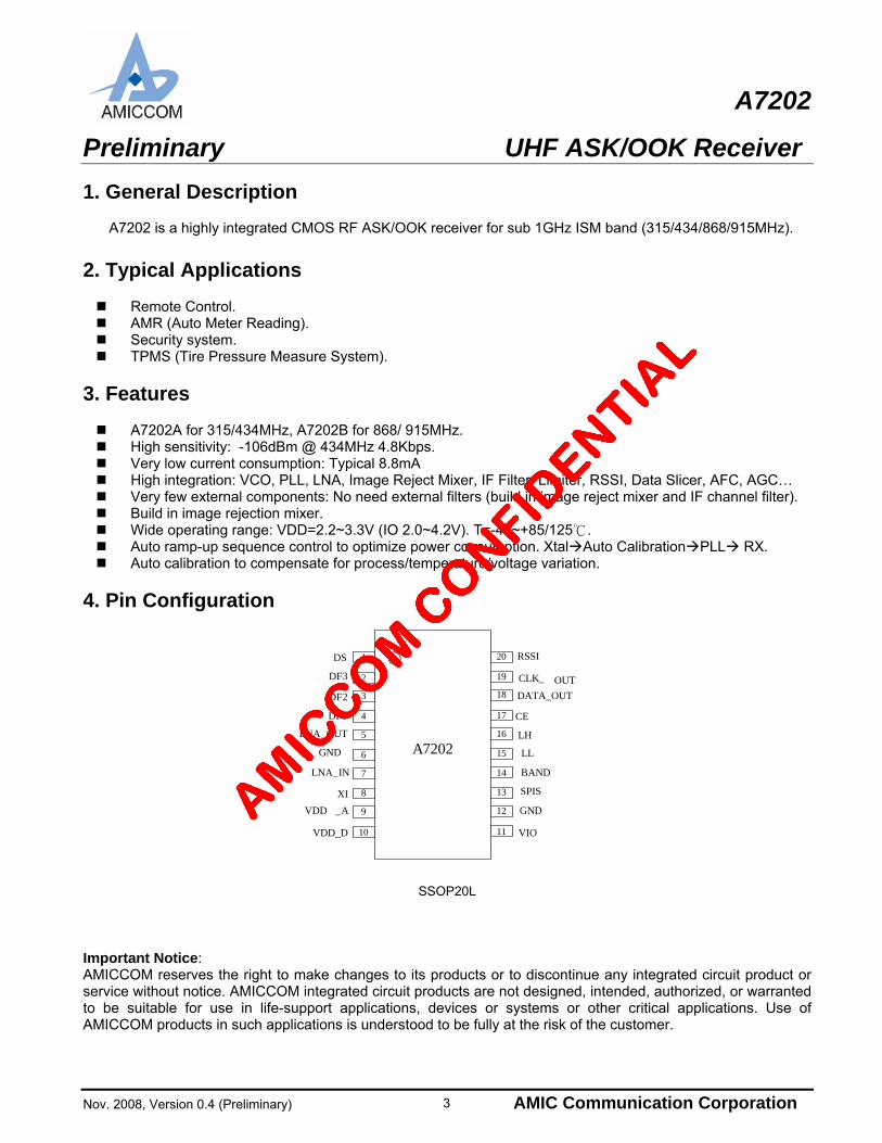
4. Pin Configuration
1
2
3
4
5
6
7
8
9
10
DS
DF3
DF2
LNA_OUT
GND
LNA_IN
XI
VDD_D
VDD _A
20
19
18
17
16
15
14
13
12
11
RSSI
CLK_ OUT
DATA_OUT
CE
LH
LL
BAND
SPIS
VIO
GND
A7202
DF1
SSOP20L
Important Notice: AMICCOM reserves the right to make changes to its products or to discontinue any integrated circuit product or service without notice. AMICCOM integrated circuit products are not designed, intended, authorized, or warranted to be suitable for use in life-support applications, devices or systems or other critical applications. Use of AMICCOM products in such applications is understood to be fully at the risk of the customer.
3
A7202
Preliminary UHF ASK/OOK Receiver
Nov. 2008, Version 0.4 (Preliminary) AMIC Communication Corporation 4
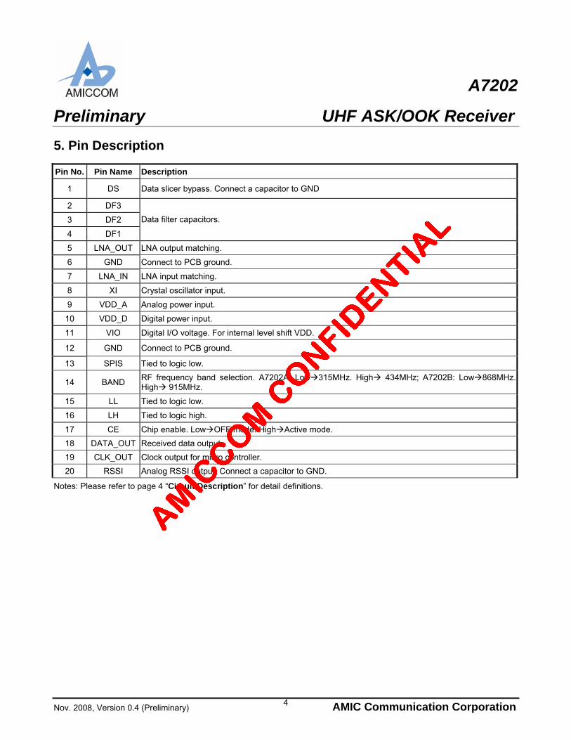
5. Pin Description
Pin No. Pin Name Description
1 DS Data slicer bypass. Connect a capacitor to GND
2 DF3
3 DF2
4 DF1
Data filter capacitors.
5 LNA_OUT LNA output matching.
6 GND Connect to PCB ground.
7 LNA_IN LNA input matching.
8 XI Crystal oscillator input.
9 VDD_A Analog power input.
10 VDD_D Digital power input.
11 VIO Digital I/O voltage. For internal level shift VDD.
12 GND Connect to PCB ground.
13 SPIS Tied to logic low.
14 BAND RF frequency band selection. A7202A: Low315MHz. High 434MHz; A7202B: Low868MHz. High 915MHz.
15 LL Tied to logic low.
16 LH Tied to logic high.
17 CE Chip enable. LowOFF mode. HighActive mode.
18 DATA_OUT Received data output.
19 CLK_OUT Clock output for micro controller.
20 RSSI Analog RSSI output. Connect a capacitor to GND.
Notes: Please refer to page 4 “Circuit Description” for detail definitions.
A7202
Preliminary UHF ASK/OOK Receiver
Nov. 2008, Version 0.4 (Preliminary) AMIC Communication Corporation
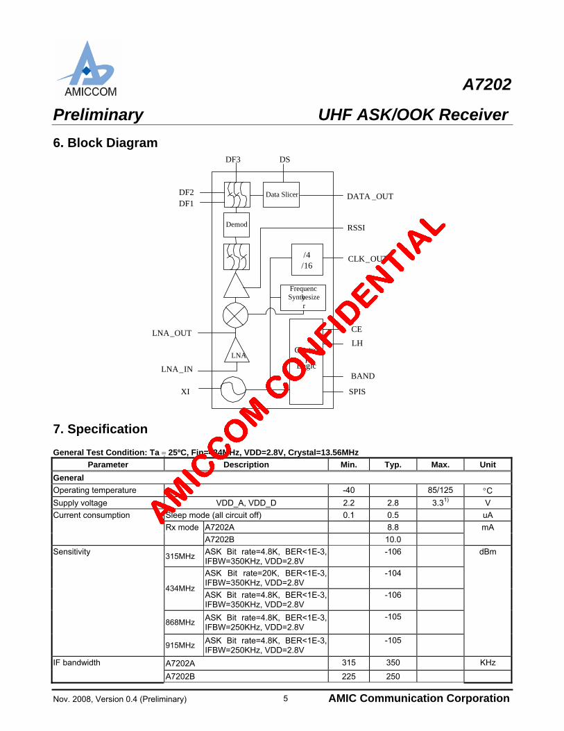
6. Block Diagram
DF2
LNA_OUT
LNA_IN
XI
RSSI
CLK_OUT
DATA _OUT
CE
LH
BAND
SPIS
Control
Logic
/4/16
LNA
Demod
Frequency Synthesizer
Data SlicerDF1
DF3 DS
7. Specification General Test Condition: Ta 25ºC, Fin=434MHz, VDD=2.8V, Crystal=13.56MHz
Parameter Description Min. Typ. Max. Unit
General
Operating temperature -40 85/125 C
Supply voltage VDD_A, VDD_D 2.2 2.8 3.31) V
Sleep mode (all circuit off) 0.1 0.5 uA
A7202A 8.8
Current consumption
Rx mode
A7202B 10.0
mA
315MHz ASK Bit rate=4.8K, BER<1E-3, IFBW=350KHz, VDD=2.8V
-106
ASK Bit rate=20K, BER<1E-3, IFBW=350KHz, VDD=2.8V
-104
434MHz ASK Bit rate=4.8K, BER<1E-3, IFBW=350KHz, VDD=2.8V
-106
868MHz ASK Bit rate=4.8K, BER<1E-3, IFBW=250KHz, VDD=2.8V
-105
Sensitivity
915MHz ASK Bit rate=4.8K, BER<1E-3, IFBW=250KHz, VDD=2.8V
-105
dBm
A7202A 315 350 KHz IF bandwidth
A7202B 225 250
5
A7202
Preliminary UHF ASK/OOK Receiver
Nov. 2008, Version 0.4 (Preliminary) AMIC Communication Corporation 6
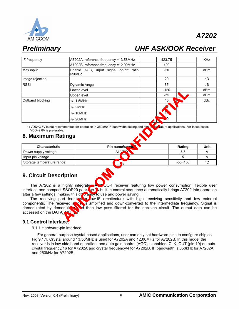
A7202A, reference frequency =13.56MHz 423.75 IF frequency
A7202B, reference frequency =12.00MHz 400
KHz
Max input Enable AGC, input signal on/off ratio >90dBc
-20 dBm
Image rejection 20 dB
Dynamic range 85 dB
Lower level -120 dBm
RSSI
Upper level -35 dBm
+/- 1.5MHz 45
+/- 2MHz 45
+/- 10MHz 55
Outband blocking
+/- 20MHz 60
dBc
1) VDD=3.3V is not recommended for operation in 350kHz-IF bandwidth setting and high temperature applications. For those cases, VDD=2.8V is preferable.
8. Maximum Ratings
Characteristic Pin name/symbol Rating Unit
Power supply voltage All VDD 5.5 V
Input pin voltage 5 V
Storage temperature range Tstg -55~150 C
9. Circuit Description
The A7202 is a highly integrated ASK/OOK receiver featuring low power consumption, flexible user interface and compact SSOP20 package. A built-in control sequence automatically brings A7202 into operation after a few settings, making this chip easy to use and power saving.
The receiving part features a low-IF architecture with high receiving sensitivity and few external components. The received signal is amplified and down-converted to the intermediate frequency. Signal is demodulated by demodulator and then low pass filtered for the decision circuit. The output data can be accessed on the DATA_OUT pin. 9.1 Control Interface:
9.1.1 Hardware-pin interface:
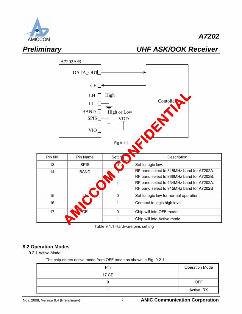
For general-purpose crystal-based applications, user can only set hardware pins to configure chip as Fig 9.1.1. Crystal around 13.56MHz is used for A7202A and 12.00MHz for A7202B. In this mode, the receiver is in low-side band operation, and auto gain control (AGC) is enabled. CLK_OUT (pin 19) outputs crystal frequency/16 for A7202A and crystal frequency/4 for A7202B. IF bandwidth is 350kHz for A7202A and 250kHz for A7202B.
A7202
Preliminary UHF ASK/OOK Receiver
Nov. 2008, Version 0.4 (Preliminary) AMIC Communication Corporation
High
VDD
DATA_OUT
CE
LH
LL
BANDSPIS
VIO
Contoller
A7202A/B
High or Low
Fig 9.1.1
Pin No Pin Name Setting Description
13 SPIS 0 Set to logic low.
0 RF band select to 315MHz band for A7202A.
RF band select to 868MHz band for A7202B. 14 BAND
1 RF band select to 434MHz band for A7202A.
RF band select to 915MHz band for A7202B
15 LL 0 Set to logic low for normal operation.
16 LH 1 Connect to logic high level.
0 Chip will into OFF mode. 17 CE
1 Chip will into Active mode.
Table 9.1.1 Hardware pins setting
9.2 Operation Modes 9.2.1 Active Mode.
The chip enters active mode from OFF mode as shown in Fig. 9.2.1.
Pin Operation Mode
17 CE
0 OFF
1 Active, RX
7
A7202
Preliminary UHF ASK/OOK Receiver
Nov. 2008, Version 0.4 (Preliminary) AMIC Communication Corporation
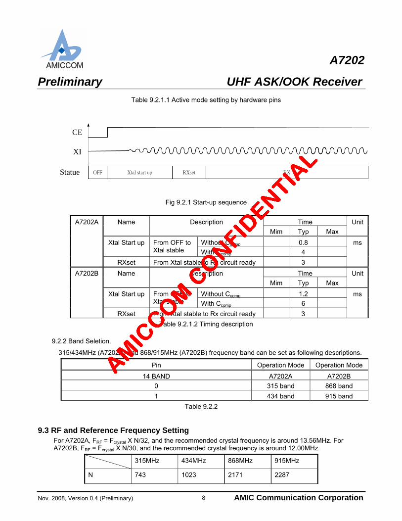
Table 9.2.1.1 Active mode setting by hardware pins
XI
CE
Statue OFF Xtal start up RXset RX
Fig 9.2.1 Start-up sequence
Time Name Description
Mim Typ Max
Unit
Without Ccomp 0.8 Xtal Start up From OFF to Xtal stable With Ccomp 4
A7202A
RXset From Xtal stable to Rx circuit ready 3
ms
Time Name Description
Mim Typ Max
Unit
Without Ccomp 1.2 Xtal Start up From OFF to Xtal stable With Ccomp 6
A7202B
RXset From Xtal stable to Rx circuit ready 3
ms
Table 9.2.1.2 Timing description
9.2.2 Band Seletion.
315/434MHz (A7202A) and 868/915MHz (A7202B) frequency band can be set as following descriptions.
Pin Operation Mode Operation Mode
14 BAND A7202A A7202B
0 315 band 868 band
1 434 band 915 band
Table 9.2.2
9.3 RF and Reference Frequency Setting For A7202A, FRF = Fcrystal X N/32, and the recommended crystal frequency is around 13.56MHz. For A7202B, FRF = Fcrystal X N/30, and the recommended crystal frequency is around 12.00MHz.
315MHz 434MHz 868MHz 915MHz
N 743 1023 2171 2287
8
A7202
Preliminary UHF ASK/OOK Receiver
Nov. 2008, Version 0.4 (Preliminary) AMIC Communication Corporation
FRF (MHz)1) 314.84625 433.49625 868.4 914.8
Table 9.3 RF channel frequency setting
1) For A7202A, FRF is given for crystal=13.560000MHz; for A7202B, FRF is given for crystal=12.000000MHz.
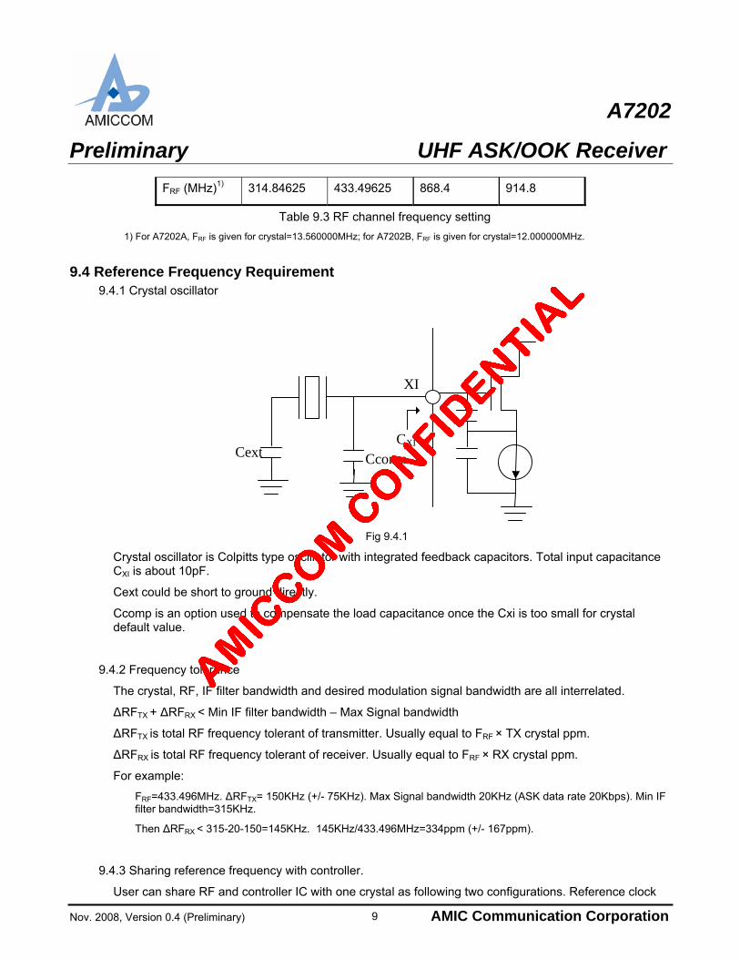
9.4 Reference Frequency Requirement
9.4.1 Crystal oscillator
XI
CextCXI
Ccomp
Fig 9.4.1
Crystal oscillator is Colpitts type oscillator with integrated feedback capacitors. Total input capacitance CXI is about 10pF.
Cext could be short to ground directly.
Ccomp is an option used to compensate the load capacitance once the Cxi is too small for crystal default value.
9.4.2 Frequency tolerance
The crystal, RF, IF filter bandwidth and desired modulation signal bandwidth are all interrelated.
ΔRFTX + ΔRFRX < Min IF filter bandwidth – Max Signal bandwidth
ΔRFTX is total RF frequency tolerant of transmitter. Usually equal to FRF × TX crystal ppm.
ΔRFRX is total RF frequency tolerant of receiver. Usually equal to FRF × RX crystal ppm.
For example:
FRF=433.496MHz. ΔRFTX= 150KHz (+/- 75KHz). Max Signal bandwidth 20KHz (ASK data rate 20Kbps). Min IF filter bandwidth=315KHz.
Then ΔRFRX < 315-20-150=145KHz. 145KHz/433.496MHz=334ppm (+/- 167ppm).
9.4.3 Sharing reference frequency with controller.
User can share RF and controller IC with one crystal as following two configurations. Reference clock
9
A7202
Preliminary UHF ASK/OOK Receiver
Nov. 2008, Version 0.4 (Preliminary) AMIC Communication Corporation
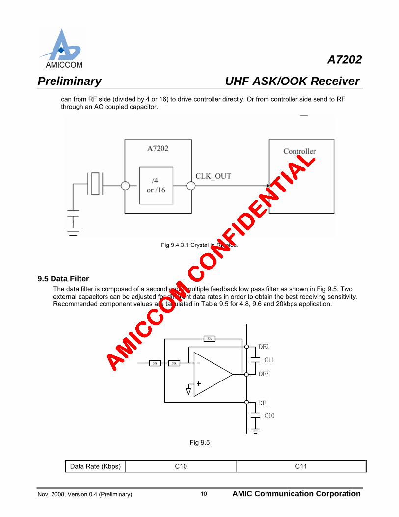
can from RF side (divided by 4 or 16) to drive controller directly. Or from controller side send to RF through an AC coupled capacitor.
Fig 9.4.3.1 Crystal in RF side.
9.5 Data Filter The data filter is composed of a second order multiple feedback low pass filter as shown in Fig 9.5. Two external capacitors can be adjusted for different data rates in order to obtain the best receiving sensitivity. Recommended component values are tabulated in Table 9.5 for 4.8, 9.6 and 20kbps application.
50k
50k
DF3
50k
DF2
C11
DF1
C10
Fig 9.5
Data Rate (Kbps) C10 C11
10
A7202
Preliminary UHF ASK/OOK Receiver
Nov. 2008, Version 0.4 (Preliminary) AMIC Communication Corporation
4.8 1nF 220pF
9.6 560pF 120pF
20 270pF 56pF
Table 9.5 Note: For other data rate, please contact AMICCOM’s FAE for recommended values.
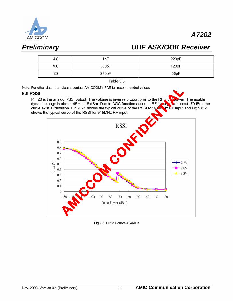
9.6 RSSI Pin 20 is the analog RSSI output. The voltage is inverse proportional to the RF input power. The usable dynamic range is about -45 ~ -115 dBm. Due to AGC function action at RF input power about -70dBm, the curve exist a transition. Fig 9.6.1 shows the typical curve of the RSSI for 434MHz RF input and Fig 9.6.2 shows the typical curve of the RSSI for 915MHz RF input.
RSSI
0
0.1
0.2
0.3
0.4
0.5
0.6
0.7
0.8
0.9
-130 -120 -110 -100 -90 -80 -70 -60 -50 -40 -30 -20
Input Power (dBm)
Vrs
si (
V)
2.2V
2.8V
3.3V
Fig 9.6.1 RSSI curve 434MHz
11
A7202
Preliminary UHF ASK/OOK Receiver
Nov. 2008, Version 0.4 (Preliminary) AMIC Communication Corporation
RSSI
0.000
0.100
0.200
0.300
0.400
0.500
0.600
0.700
0.800
0.900
-130 -120 -110 -100 -90 -80 -70 -60 -50 -40 -30 -20
Input Power (dBm)
Vrs
si (
V)
2.2V
2.8V
3.3V
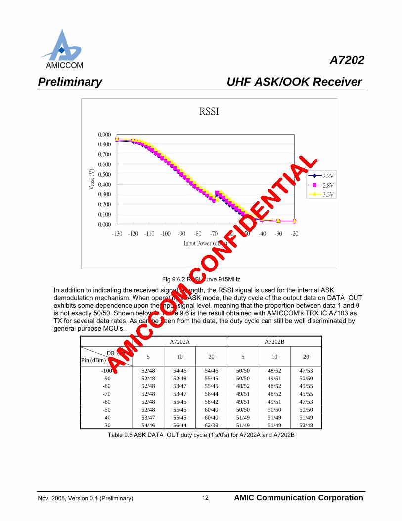
Fig 9.6.2 RSSI curve 915MHz
In addition to indicating the received signal strength, the RSSI signal is used for the internal ASK demodulation mechanism. When operating in ASK mode, the duty cycle of the output data on DATA_OUT exhibits some dependence upon the input signal level, meaning that the proportion between data 1 and 0 is not exactly 50/50. Shown below in Table 9.6 is the result obtained with AMICCOM’s TRX IC A7103 as TX for several data rates. As can be seen from the data, the duty cycle can still be well discriminated by general purpose MCU’s.
A7202A A7202B
DR (kbps) Pin (dBm) 5 10 20 5 10 20
-100 52/48 54/46 54/46 50/50 48/52 47/53 -90 52/48 52/48 55/45 50/50 49/51 50/50 -80 52/48 53/47 55/45 48/52 48/52 45/55 -70 52/48 53/47 56/44 49/51 48/52 45/55 -60 52/48 55/45 58/42 49/51 49/51 47/53 -50 52/48 55/45 60/40 50/50 50/50 50/50 -40 53/47 55/45 60/40 51/49 51/49 51/49 -30 54/46 56/44 62/38 51/49 51/49 52/48
Table 9.6 ASK DATA_OUT duty cycle (1’s/0’s) for A7202A and A7202B
12
A7202
Preliminary UHF ASK/OOK Receiver
Nov. 2008, Version 0.4 (Preliminary) AMIC Communication Corporation
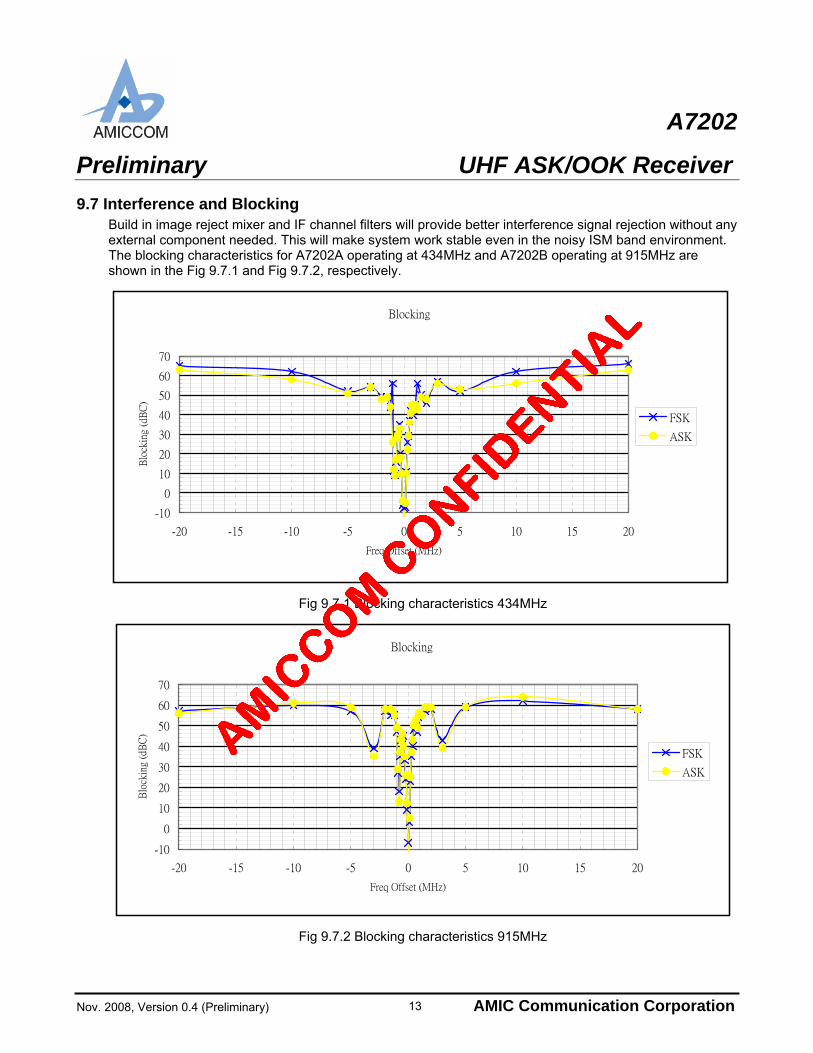
9.7 Interference and Blocking Build in image reject mixer and IF channel filters will provide better interference signal rejection without any external component needed. This will make system work stable even in the noisy ISM band environment. The blocking characteristics for A7202A operating at 434MHz and A7202B operating at 915MHz are shown in the Fig 9.7.1 and Fig 9.7.2, respectively.
Blocking
-10
0
10
20
30
40
50
60
70
-20 -15 -10 -5 0 5 10 15 20
Freq Offset (MHz)
Blo
ckin
g (d
BC
)
FSK
ASK
Fig 9.7.1 Blocking characteristics 434MHz
Blocking
-10
0
10
20
30
40
50
60
70
-20 -15 -10 -5 0 5 10 15 20
Freq Offset (MHz)
Blo
ckin
g (d
BC
)
FSK
ASK
Fig 9.7.2 Blocking characteristics 915MHz
13
A7202
Preliminary UHF ASK/OOK Receiver
Nov. 2008, Version 0.4 (Preliminary) AMIC Communication Corporation 14
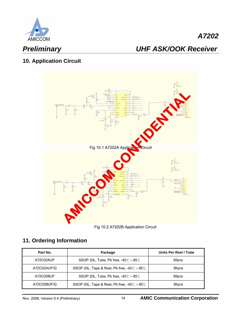
10. Application Circuit
J4 SMA CONNECTOR
gnd
C15100pF
gnd
VCCC3
500pF
gnd
C4
100pF
C100.22uF
gnd
C1156p
C8270pF
gnd VCC
C5
x
gnd
Y1
CRYSTAL
gnd
gnd
L247nH
gnd
C2
100pF
L133nH
C1
2pF
gnd
C72.2uF
gnd
DATA_OUT_IO
CLK_OUT_IO
VCC
CE
12
J1
CON/2P 1.27
12
J2
CON/2P 1.27gnd
gnd
gnd
VCC
C16x
gnd
gnd
BAND
gnd
VDD_IO
12345678910111213
J3
CON/13P 1.27
VDD_IO
BAND
CE
DATA_OUT_IOCLK_OUT_IO
C6x
gnd
R1
0R
C910pF
gnd
DS1
DF32
DF23
DF14
LNA_OUT5
GND6
LNA_IN7
XI8
VDD_A9
VDD_D10 VIO 11
GND 12
SPIS 13
BAND 14
LL 15
LH 16
CE 17
DATA_OUT 18
CLK_OUT 19
RSSI 20
U1
A7202
L3
0
C12X
C13X
gnd gnd
Fig 10.1 A7202A Application Circuit
J4 SMA CONNECTOR
gnd
C15100pF
gnd
VCCC3
500pF
gnd
C4
100pF
C100.22uF
gnd
C1156p
C8270pFgnd
VCC
C5
x
gnd
Y1
CRYSTAL
gnd
gnd
L218nH
gnd
C2
100pF
L16.8nH
C1
1.5pF
gnd
C72.2uF
gnd
DATA_OUT_IO
CLK_OUT_IO
VCC
CE
12
J1
CON/2P 1.27
12
J2
CON/2P 1.27gnd
gnd
gnd
VCC
C16120pF
gnd
GND
BAND
GND
VDD_IO
12345678910111213
J3
CON/13P 1.27
VDD_IO
BAND
CE
DATA_OUT_IOCLK_OUT_IO
C6x
gnd
BP_DS1
DF32
DF23
DF14
LNA_OUT5
GND6
LNA_IN7
XI8
VDD_A9
VDD_DIG10 VDD_IO 11
GND 12
SPIS 13
BAND 14
CH 15
FSK_ASK 16
CE17
DATA_OUT 18
CLK_OUT 19
BP_RSSI 20
U1
A7202_SSOP20
R1
0R
C910pF
gnd
L3
0
C12X
C13X
gnd gnd
Fig 10.2 A7202B Application Circuit
11. Ordering Information
Part No. Package Units Per Reel / Tube
A72C02AUF SSOP 20L, Tube, Pb free, -40℃~85℃ 56pcs
A72C02AUF/Q SSOP 20L, Tape & Reel, Pb free, -40℃~85℃ 3Kpcs
A72C02BUF SSOP 20L, Tube, Pb free, -40℃~85℃ 56pcs
A72C02BUF/Q SSOP 20L, Tape & Reel, Pb free, -40℃~85℃ 3Kpcs
A7202
Preliminary UHF ASK/OOK Receiver
Nov. 2008, Version 0.4 (Preliminary) AMIC Communication Corporation
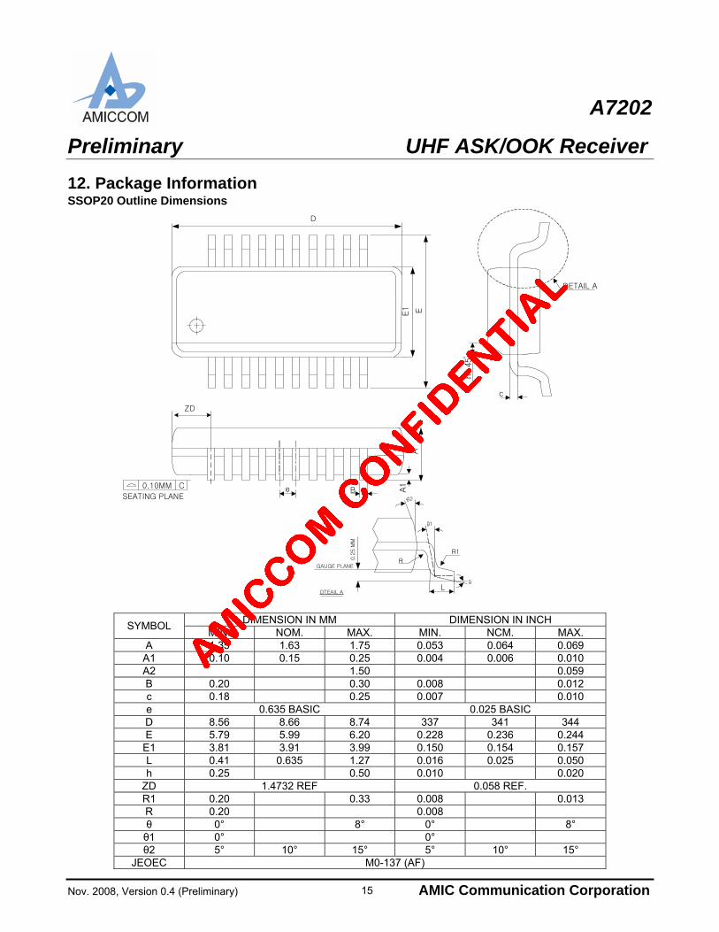
12. Package Information SSOP20 Outline Dimensions
GAUGE PLANE
DTEAIL A
0.2
5 M
M
2
1
R1
L
R
D
EE1
ZDA
A1
Be0.10MM C
SEATING PLANE
hx45
c
DETAIL A
DIMENSION IN MM DIMENSION IN INCH SYMBOL
MIN. NOM. MAX. MIN. NCM. MAX. A 1.35 1.63 1.75 0.053 0.064 0.069 A1 0.10 0.15 0.25 0.004 0.006 0.010 A2 1.50 0.059 B 0.20 0.30 0.008 0.012 c 0.18 0.25 0.007 0.010 e 0.635 BASIC 0.025 BASIC D 8.56 8.66 8.74 337 341 344 E 5.79 5.99 6.20 0.228 0.236 0.244 E1 3.81 3.91 3.99 0.150 0.154 0.157 L 0.41 0.635 1.27 0.016 0.025 0.050 h 0.25 0.50 0.010 0.020
ZD 1.4732 REF 0.058 REF. R1 0.20 0.33 0.008 0.013 R 0.20 0.008 θ 0° 8° 0° 8° θ1 0° 0° θ2 5° 10° 15° 5° 10° 15°
JEOEC M0-137 (AF)
15
A7202
Preliminary UHF ASK/OOK Receiver
Nov. 2008, Version 0.4 (Preliminary) AMIC Communication Corporation
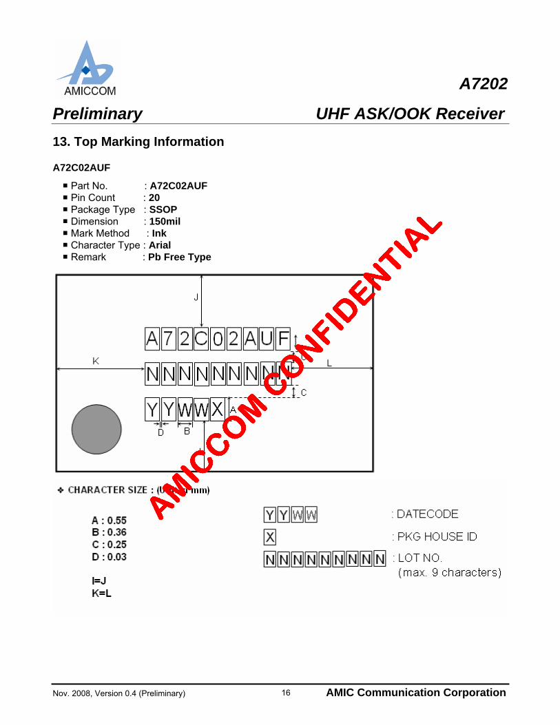
13. Top Marking Information A72C02AUF
Part No. : A72C02AUF
Pin Count : 20
Package Type : SSOP Dimension : 150mil
Mark Method : Ink Character Type : Arial Remark : Pb Free Type
16
A7202
Preliminary UHF ASK/OOK Receiver
Nov. 2008, Version 0.4 (Preliminary) AMIC Communication Corporation
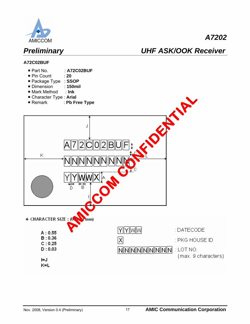
A72C02BUF
Part No. : A72C02BUF Pin Count : 20
Package Type : SSOP Dimension : 150mil
Mark Method : Ink Character Type : Arial Remark : Pb Free Type
17
A7202
Preliminary UHF ASK/OOK Receiver
Nov. 2008, Version 0.4 (Preliminary) AMIC Communication Corporation
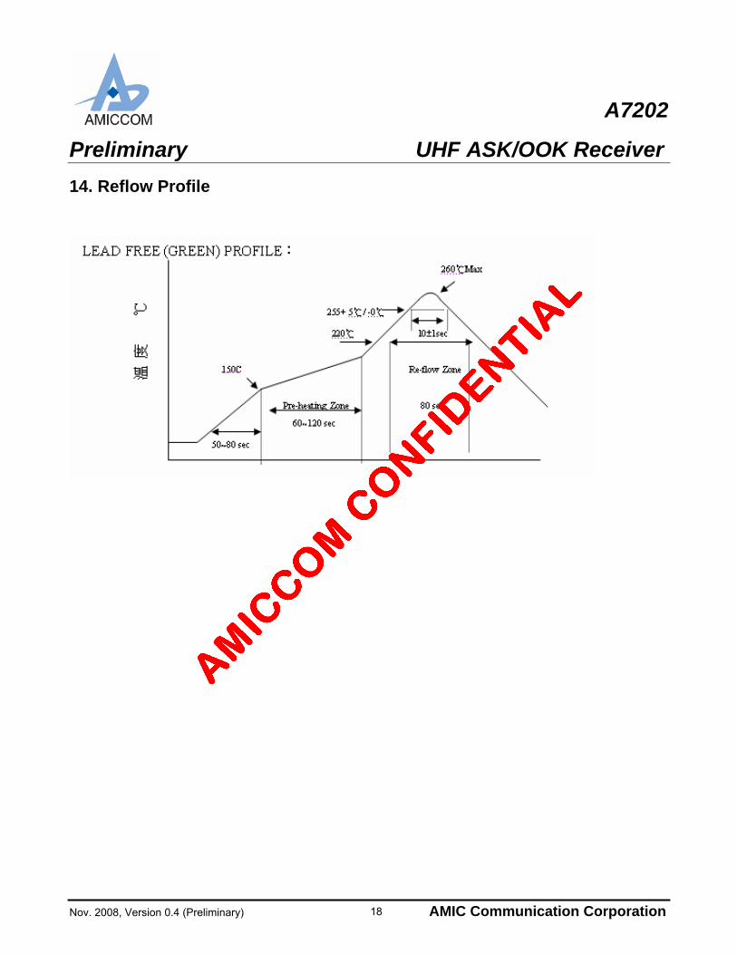
14. Reflow Profile
18
A7202
Preliminary UHF ASK/OOK Receiver
Nov. 2008, Version 0.4 (Preliminary) AMIC Communication Corporation
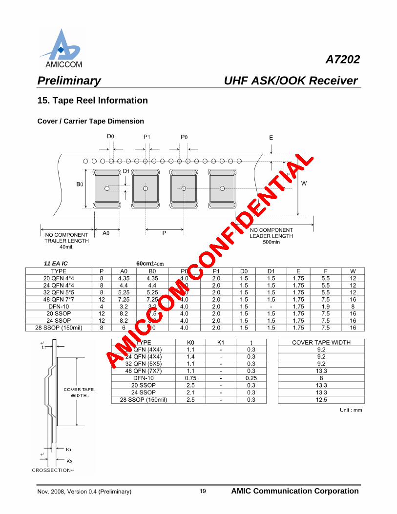
15. Tape Reel Information Cover / Carrier Tape Dimension
A0 NO COMPONENT TRAILER LENGTH
40mil.
NO COMPONENT LEADER LENGTH
500min
P
P1 P0 D0 E
F D1
W B0
11 EA IC 60cm±4cm
TYPE P A0 B0 P0 P1 D0 D1 E F W 20 QFN 4*4 8 4.35 4.35 4.0 2.0 1.5 1.5 1.75 5.5 12 24 QFN 4*4 8 4.4 4.4 4.0 2.0 1.5 1.5 1.75 5.5 12 32 QFN 5*5 8 5.25 5.25 4.0 2.0 1.5 1.5 1.75 5.5 12 48 QFN 7*7 12 7.25 7.25 4.0 2.0 1.5 1.5 1.75 7.5 16
DFN-10 4 3.2 3.2 4.0 2.0 1.5 - 1.75 1.9 8 20 SSOP 12 8.2 7.5 4.0 2.0 1.5 1.5 1.75 7.5 16 24 SSOP 12 8.2 8.8 4.0 2.0 1.5 1.5 1.75 7.5 16
28 SSOP (150mil) 8 6 10 4.0 2.0 1.5 1.5 1.75 7.5 16
TYPE K0 K1 t COVER TAPE WIDTH 20 QFN (4X4) 1.1 - 0.3 9.2 24 QFN (4X4) 1.4 - 0.3 9.2 32 QFN (5X5) 1.1 - 0.3 9.2 48 QFN (7X7) 1.1 - 0.3 13.3
DFN-10 0.75 - 0.25 8 20 SSOP 2.5 - 0.3 13.3 24 SSOP 2.1 - 0.3 13.3
28 SSOP (150mil) 2.5 - 0.3 12.5
Unit : mm
19
A7202
Preliminary UHF ASK/OOK Receiver
Nov. 2008, Version 0.4 (Preliminary) AMIC Communication Corporation
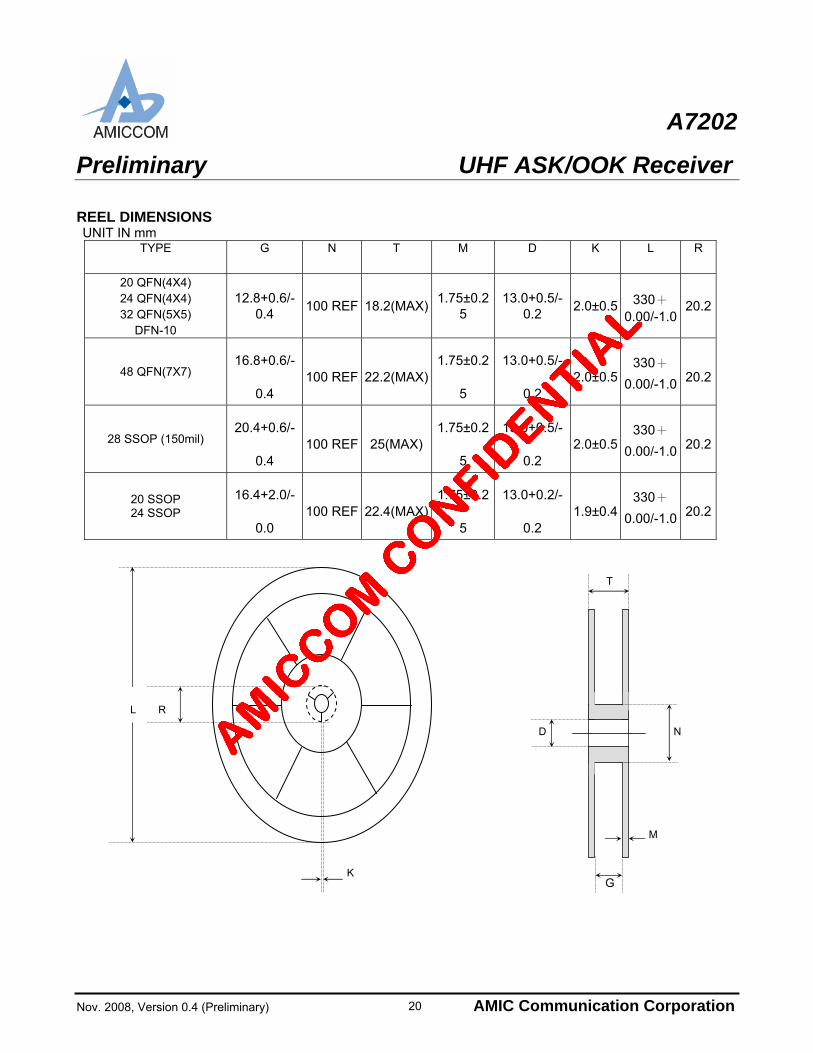
REEL DIMENSIONS UNIT IN mm
TYPE G N T M D K L R
20 QFN(4X4) 24 QFN(4X4) 32 QFN(5X5)
DFN-10
12.8+0.6/-0.4
100 REF 18.2(MAX)1.75±0.2
5 13.0+0.5/-
0.2 2.0±0.5 330+
0.00/-1.020.2
48 QFN(7X7) 16.8+0.6/-
0.4 100 REF 22.2(MAX)
1.75±0.2
5
13.0+0.5/-
0.2 2.0±0.5
330+
0.00/-1.0 20.2
28 SSOP (150mil) 20.4+0.6/-
0.4 100 REF 25(MAX)
1.75±0.2
5
13.0+0.5/-
0.2 2.0±0.5
330+
0.00/-1.0 20.2
20 SSOP 24 SSOP
16.4+2.0/-
0.0 100 REF 22.4(MAX)
1.75±0.2
5
13.0+0.2/-
0.2 1.9±0.4
330+
0.00/-1.0 20.2
20
K
R L
T
D
G
M
N