Embed Size (px)
Citation preview

A72A OWNERS MANUAL
Manual No. 999967 Rev. 9/2/2003
Serial No. __________________ Mailing Address: P.O. Box 580697 Tulsa, OK 74158-0697 Physical Address: Phone (918) 836-0463 4707 N. Mingo Rd. Fax (918) 834-5979 Tulsa, OK 74117-5904 http://www.autocrane.com


To: Fax:From: Date:Re: Pages:
Name: Phone:Address:City: State: Zip:Contact:
Name:Address:City: State: Zip:Contact:
VIN #
ONE REGISTRATION FORM PER UNIT (CRANE OR BODY)Registration form must be mailed or faxed within 15 days of customer installation.
Mail to:Warranty DepartmentAuto Crane Company
P.O. Box 581510Tulsa, OK 74158-0697
Date Product Delivered: Date Processed:** For Auto Crane use only
Product Information: (Required for Warranty Activation)
Model No.: Serial No.:
E-mail Address:
Distributor Information: (Required for Warranty Activation)
Product Registration
E-mail Address:
(Required for Warranty Activation)
Auto Crane Warranty Registration
(918) 834-5979Warranty Department
End User Information:
Fax Transmission
Warranty Registration Rev. 072403


A72A ARTICULATING CRANE MOUNTING AND INSTALLATION INSTRUCTIONS REVISION RECORD
i
Revision
Date
Section(s) Or
Page(s) Description of Change
09/02/03 Last page New 2-year warranty policy to replace 1-year warranty policy

WARNINGS
READ THIS PAGE
Warnings 12/2002
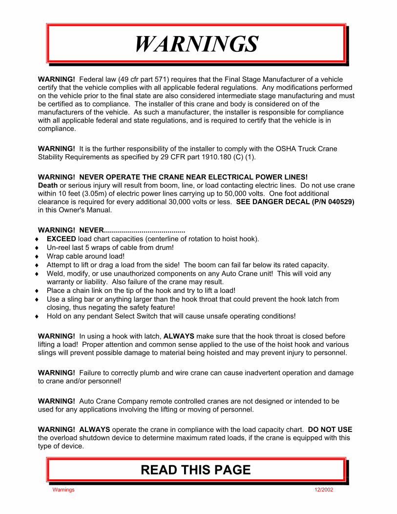
WARNING! Federal law (49 cfr part 571) requires that the Final Stage Manufacturer of a vehicle certify that the vehicle complies with all applicable federal regulations. Any modifications performed on the vehicle prior to the final state are also considered intermediate stage manufacturing and must be certified as to compliance. The installer of this crane and body is considered on of the manufacturers of the vehicle. As such a manufacturer, the installer is responsible for compliance with all applicable federal and state regulations, and is required to certify that the vehicle is in compliance. WARNING! It is the further responsibility of the installer to comply with the OSHA Truck Crane Stability Requirements as specified by 29 CFR part 1910.180 (C) (1). WARNING! NEVER OPERATE THE CRANE NEAR ELECTRICAL POWER LINES! Death or serious injury will result from boom, line, or load contacting electric lines. Do not use crane within 10 feet (3.05m) of electric power lines carrying up to 50,000 volts. One foot additional clearance is required for every additional 30,000 volts or less. SEE DANGER DECAL (P/N 040529) in this Owner's Manual. WARNING! NEVER.........................................
♦ EXCEED load chart capacities (centerline of rotation to hoist hook). ♦ Un-reel last 5 wraps of cable from drum! ♦ Wrap cable around load! ♦ Attempt to lift or drag a load from the side! The boom can fail far below its rated capacity. ♦ Weld, modify, or use unauthorized components on any Auto Crane unit! This will void any
warranty or liability. Also failure of the crane may result. ♦ Place a chain link on the tip of the hook and try to lift a load! ♦ Use a sling bar or anything larger than the hook throat that could prevent the hook latch from
closing, thus negating the safety feature! ♦ Hold on any pendant Select Switch that will cause unsafe operating conditions! WARNING! In using a hook with latch, ALWAYS make sure that the hook throat is closed before lifting a load! Proper attention and common sense applied to the use of the hoist hook and various slings will prevent possible damage to material being hoisted and may prevent injury to personnel. WARNING! Failure to correctly plumb and wire crane can cause inadvertent operation and damage to crane and/or personnel! WARNING! Auto Crane Company remote controlled cranes are not designed or intended to be used for any applications involving the lifting or moving of personnel. WARNING! ALWAYS operate the crane in compliance with the load capacity chart. DO NOT USE the overload shutdown device to determine maximum rated loads, if the crane is equipped with this type of device.

AW-414 2/2000
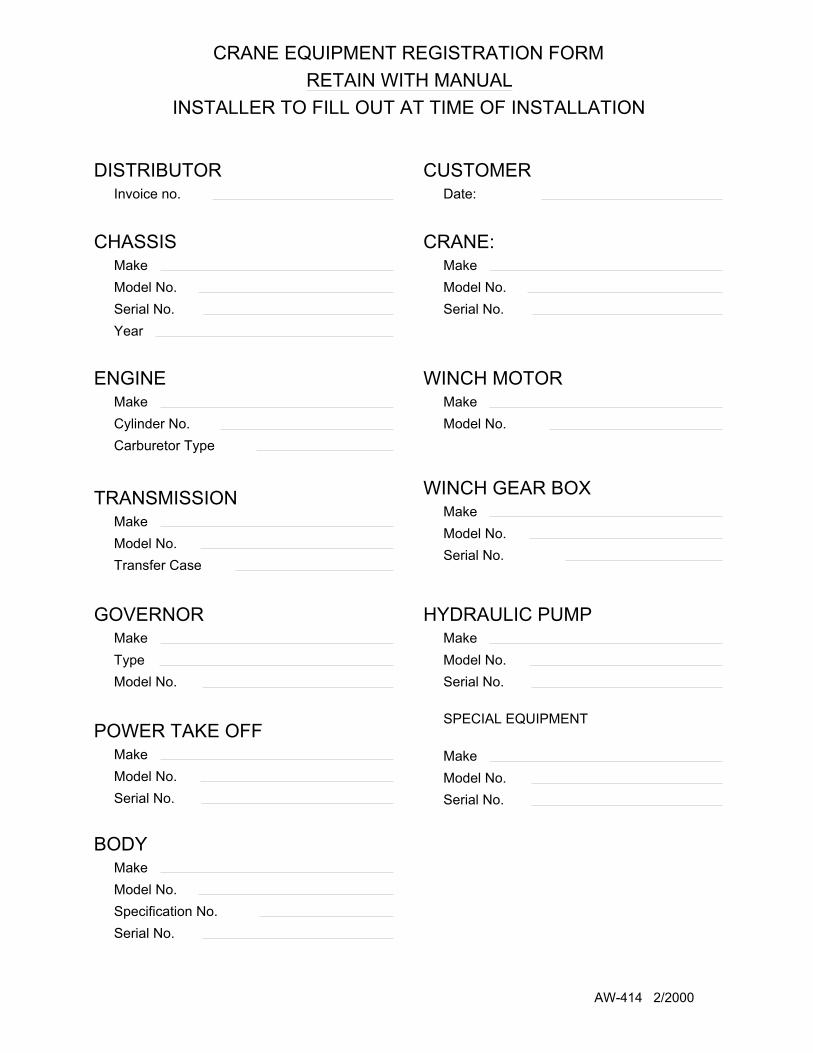
CRANE EQUIPMENT REGISTRATION FORMRETAIN WITH MANUAL
INSTALLER TO FILL OUT AT TIME OF INSTALLATION
CHASSISMakeModel No.Serial No.Year
DISTRIBUTORInvoice no.
Cylinder No.Carburetor Type
MakeENGINE
Transfer Case Model No.
TRANSMISSIONMake
MakeTypeModel No.
GOVERNOR
MakeModel No.Serial No.
POWER TAKE OFF
Serial No.
Model No.Specification No.
MakeBODY
Serial No.
Model No.Serial No.
MakeHYDRAULIC PUMP
Model No.
WINCH MOTOR
Model No.Make
MakeWINCH GEAR BOX
Model No.Serial No.
MakeCRANE:
CUSTOMERDate:
SPECIAL EQUIPMENT
Serial No.Model No.Make
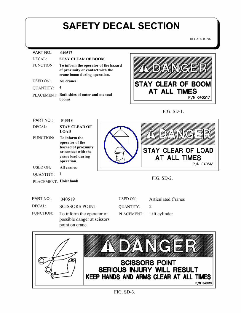
SAFETY DECAL SECTIONDECALS R7/96
Both sides of outer and manualbooms
PLACEMENT:
4QUANTITY:All cranesUSED ON:
To inform the operator of the hazardof proximity or contact with thecrane boom during operation.
FUNCTION:STAY CLEAR OF BOOMDECAL: 040517PART NO.:
Hoist hookPLACEMENT:
1QUANTITY:All cranesUSED ON:
To inform theoperator of thehazard of proximityor contact with thecrane load duringoperation.
FUNCTION:
STAY CLEAR OFLOAD
DECAL: 040518PART NO.:
FIG. SD-1.
Lift cylinderPLACEMENT:To inform the operator ofpossible danger at scissorspoint on crane.
FUNCTION:
2QUANTITY:SCISSORS POINTDECAL:
Articulated CranesUSED ON: 040519PART NO.:
FIG. SD-3.
FIG. SD-2.
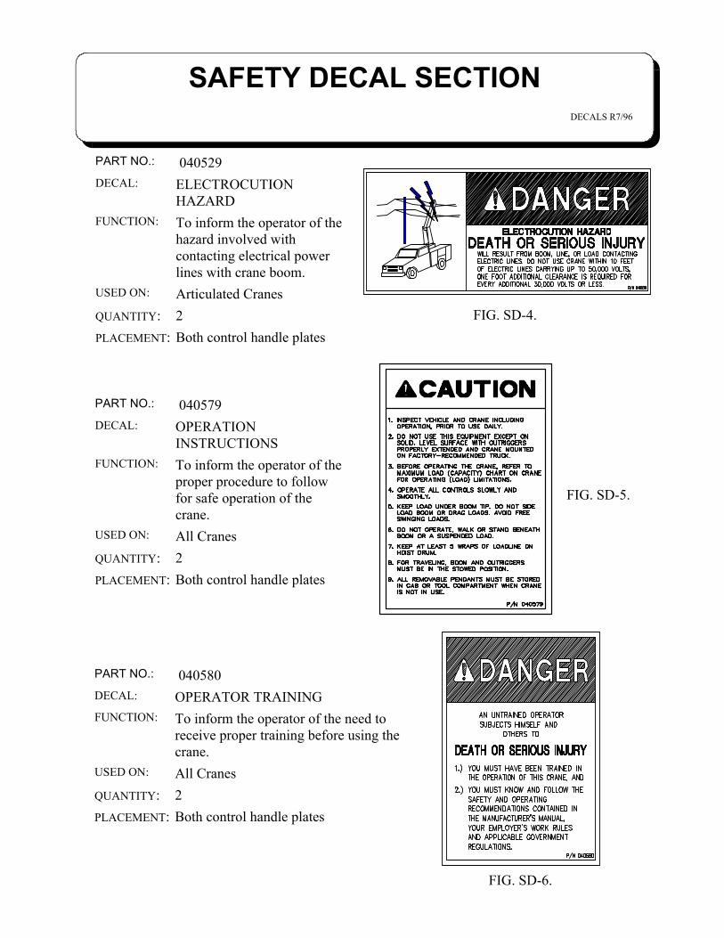
SAFETY DECAL SECTIONDECALS R7/96
Both control handle platesPLACEMENT:2QUANTITY:Articulated CranesUSED ON:
To inform the operator of thehazard involved withcontacting electrical powerlines with crane boom.
FUNCTION:
ELECTROCUTIONHAZARD
DECAL:
040529PART NO.:
FIG. SD-4.
Both control handle platesPLACEMENT:2QUANTITY:All CranesUSED ON:
To inform the operator of theproper procedure to followfor safe operation of thecrane.
FUNCTION:
OPERATIONINSTRUCTIONS
DECAL:
040579PART NO.:
FIG. SD-5.
Both control handle platesPLACEMENT:2QUANTITY:All CranesUSED ON:
To inform the operator of the need toreceive proper training before using thecrane.
FUNCTION:OPERATOR TRAININGDECAL:
040580PART NO.:
FIG. SD-6.
SAFETY DECAL SECTIONDECALS R7/96
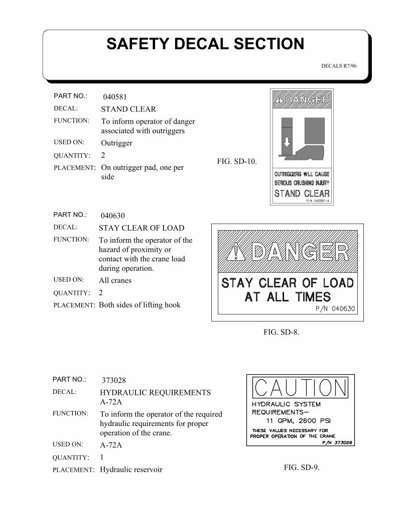
On outrigger pad, one perside
PLACEMENT:2QUANTITY:OutriggerUSED ON:
To inform operator of dangerassociated with outriggers
FUNCTION:
STAND CLEARDECAL: 040581PART NO.:
FIG. SD-10.
FIG. SD-8.
Hydraulic reservoirPLACEMENT:1QUANTITY:A-72AUSED ON:
To inform the operator of the required hydraulic requirements for properoperation of the crane.
FUNCTION:
HYDRAULIC REQUIREMENTSA-72A
DECAL: 373028PART NO.:
FIG. SD-9.
Both sides of lifting hookPLACEMENT:2QUANTITY:All cranes USED ON:
To inform the operator of thehazard of proximity orcontact with the crane loadduring operation.
FUNCTION:
STAY CLEAR OF LOADDECAL:
040630PART NO.:
SAFETY DECAL SECTIONDECALS R7/96
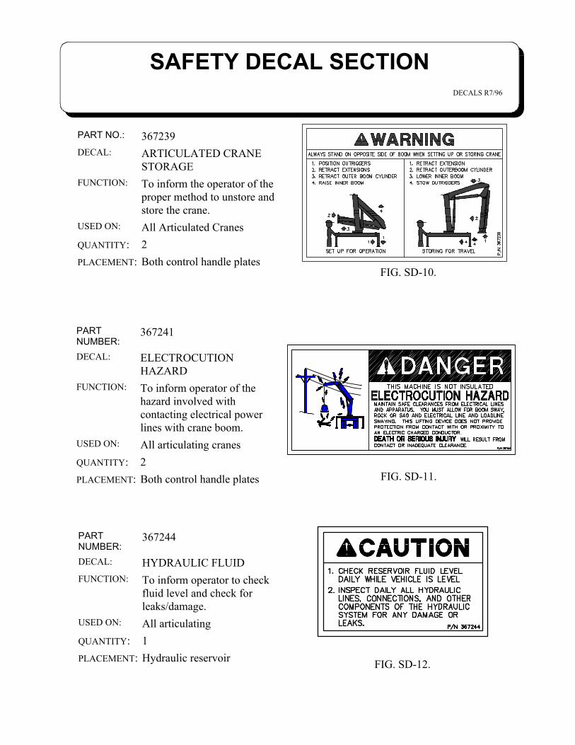
Both control handle platesPLACEMENT:2QUANTITY:All articulating cranesUSED ON:
To inform operator of thehazard involved withcontacting electrical powerlines with crane boom.
FUNCTION:
ELECTROCUTIONHAZARD
DECAL:
367241PARTNUMBER:
Both control handle platesPLACEMENT:2QUANTITY:All Articulated CranesUSED ON:
To inform the operator of theproper method to unstore andstore the crane.
FUNCTION:
ARTICULATED CRANESTORAGE
DECAL:367239PART NO.:
FIG. SD-10.
FIG. SD-11.
Hydraulic reservoirPLACEMENT:1QUANTITY:All articulatingUSED ON:
To inform operator to checkfluid level and check forleaks/damage.
FUNCTION:
HYDRAULIC FLUIDDECAL:
367244PARTNUMBER:
FIG. SD-12.
SAFETY DECAL SECTIONDECALS R7/96
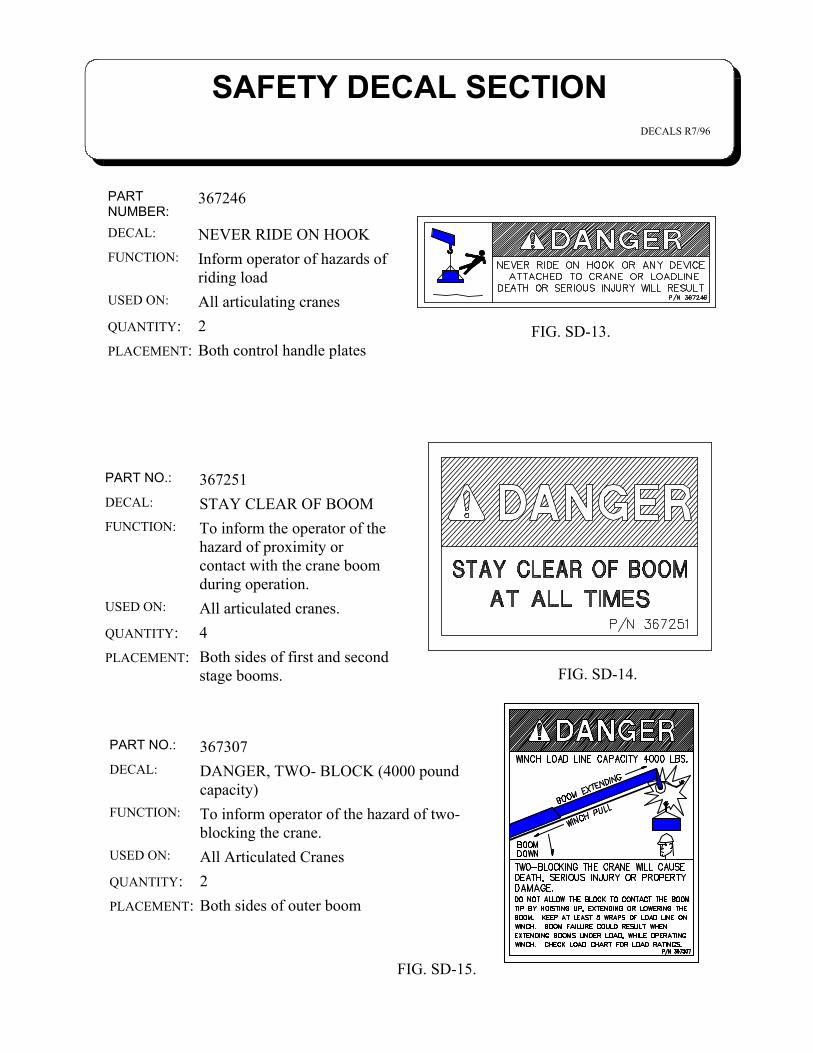
Both control handle platesPLACEMENT:2QUANTITY:All articulating cranesUSED ON:
Inform operator of hazards ofriding load
FUNCTION:
NEVER RIDE ON HOOKDECAL:
367246PARTNUMBER:
FIG. SD-13.
Both sides of first and secondstage booms.
PLACEMENT:4QUANTITY:All articulated cranes.USED ON:
To inform the operator of thehazard of proximity orcontact with the crane boomduring operation.
FUNCTION:STAY CLEAR OF BOOMDECAL:
367251PART NO.:
FIG. SD-14.
Both sides of outer boomPLACEMENT:2QUANTITY:All Articulated CranesUSED ON:
To inform operator of the hazard of two-blocking the crane.
FUNCTION:
DANGER, TWO- BLOCK (4000 poundcapacity)
DECAL:367307PART NO.:
FIG. SD-15.
SAFETY DECAL SECTIONDECALS R7/96
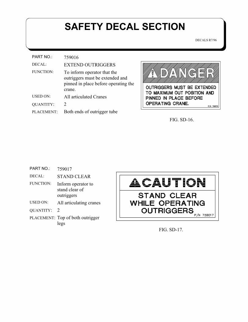
Both ends of outrigger tubePLACEMENT:2QUANTITY:All articulated CranesUSED ON:
To inform operator that theoutriggers must be extended andpinned in place before operating thecrane.
FUNCTION:
EXTEND OUTRIGGERSDECAL:759016PART NO.:
FIG. SD-16.
Top of both outriggerlegs
PLACEMENT:2QUANTITY:All articulating cranesUSED ON:
Inform operator tostand clear ofoutriggers
FUNCTION:
STAND CLEARDECAL:759017PART NO.:
FIG. SD-17.


TABLE OF CONTENTSA-72A SERIES
INTRODUCTION A-72A 1-1.0.0
SAFETY TIPS AND PRECAUTIONS 2-1.0.0
MOUNTING AND INSTALLATION 3-1.0.0
OPERATION OF UNIT / OUTRIGGERS 4-1.0.0
INSPECTION, TESTING, AND MAINTENANCE 5-1.0.0
TROUBLESHOTING 6-1.0.0
MECHANICAL SECTION 7-1.0.0
PROPORTIONAL CONTROL SYSTEM 8-1.0.0
HYDRAUILC SECTION 9-1.0.0
DECAL LAYOUT 10-1.0.0
GENERAL DIMENSIONS 11-1.0.0
LOAD CHART 12-1.0.0
WARRANTY LAST PAGE

INTRODUCTIONA-72A SERIES
1-1.0.02/2000
Auto Crane products are designed to providemany years of safe, trouble-free, dependableservice when properly used and maintained.
To assist you in obtaining the best servicefrom your crane and to avoid untimely crane and/orvehicle failure, this manual provides the followingoperating and service instructions. It is specificallyrecommended that all operating and servicepersonnel consider this manual as mandatorymaterial for reading and study before operating orservicing Auto crane products. It is highlyrecommended that crane owners, equipmentmanagers and supervisors also read this manual.
Auto Crane has incorporated several safetyfeatures in the A-72A series cranes for yourprotection. The choice of materials and the designof the electrical system minimizes weight andlengthens durability. Holding valves prevent theload from dropping if a hose should fail. A 10ufilter in the return line of the hydraulic systemremoves dirt and grit that may cause erraticoperation. The reservoir has a 15u air filter in thefiller cap. The pump has a 100 mesh strainer inthe suction line.
For your convenience the overall dimensionsof the A-72A series crane are on the GeneralDimension Drawing.Remember, the crane adds weight to the vehicle.
Adding weight may change the driving and ridingcharacteristics of the vehicle unless the appropriateoverload spring(s) are installed on the truck. Thepayload of the vehicle is reduced by the weight ofthe crane. The operator should exercise care whenloading the vehicle. Distributing the payload on thevehicle evenly will greatly improve the driving andriding characteristics of the vehicle. A minimumG.V.W. of 26,000 lbs. is recommended formounting the A-72A series cranes.Auto Crane Company issues alimited warranty certificate with eachunit sold. See last page for warranty It has always been Auto Crane Companypolicy to handle all warranty claims we receive aspromptly as possible. If a warranty claim involvesdiscrepant material or workmanship, Auto Cranewill take immediate corrective action. It isunderstandable that Auto Crane company cannotassume responsibility of liability when it is obviousthat our products have been abused, mis-used,overloaded or otherwise damaged by inexperiencedpersons trying to operate the equipment withoutreading the manual.
Auto Crane will not assumeresponsibility or liability for anymodifications or changes made to unit, orinstallation of component parts donewithout authorization.
Auto Crane maintains a strong distributornetwork and a knowledgeable Customer ServiceDepartment. In most cases, an equipmentproblem is solved via phone conversation with ourcustomer service department. The customerservice department also has the ability to bring alocal distributor, a regional sales manager, or afactory serviceman into the solution of anequipment problem. If, through no fault of Autocrane company, it is necessary to send anexperienced factory serviceman on a field servicecall, the rates stated in the Auto CraneDistributor's Flat Rate Manual will apply.
Auto Crane Company's extensive Researchand Development Program allow our customers touse the best equipment on the market. OurEngineering Staff and our knowledgeable salespeople, are always available to our customers insolving crane and winch-type applicationproblems. When in doubt, call the Auto Cranefactory.
DISTRIBUTOR ASSISTANCE:Should you require any assistance not
given in this manual, we recommend that youconsult your nearest Auto Crane Distributor.Our distributors sell authorized parts andhave service departments that can solvealmost any needed repair.
NOTE: THIS MANUAL SHOULD REMAIN
WITH THE CRANE AT ALL TIMES.
This manual does not cover all maintenance,operating, or repair instructions pertinent to allpossible situations. If you require additionalinformation, please contact the Auto CraneCompany at the following telephone number:(918) 836-0463. The information contained in themanual is in effect at the time of this printing.Auto Crane Company reserves the right to updatethis material without notice or obligation.

The Auto Crane A-72A knuckle boom is anall hydraulic crane in the 72,000 ft-lb ratingclass. It is suitable for both hook and attach-ment service.
The A-72A comes in the followingvariations:
A-72A two stage hydraulic extension with ahorizontal reach of 26'-3" (8.0m) with "crossmounted" controls located on each side ofcrane.
A-72A two stage hydraulic extension withone self storing manual boom with a horizontalreach of 32'-10" (9.9m) with "cross mounted"controls located on each side of crane.
The main components of the crane are:1. Outriggers2. Crane Base Assembly3. Rotation System4. Control Valve5. Pedestal Assembly6. Inner Boom7. Lift Cylinder8. Outer Boom9. Outer Boom Cylinder
10. Telescoping Boom Section(s) and ExtensionCylinder
11. Manual Boom12. Reservoir
OUTRIGGERSThe outriggers are extended manually, (on
sealed roller bearings) in the horizontal direc-tion and are raised and lowered hydraulically.(Optional hydraulic in-out). Outriggers areoperated by two sections from the main controlvalve. Outrigger cylinders have mounteddirectly to them a dual pilot operated checkvalve which will close if a hose break occurs,preventing any uncontrolled movement ofoutrigger cylinder and to prevent an outriggercylinder from drifting down once they havebeen stowed. Outrigger span is 12'-7" (3.8m)extended. Once outriggers are extended orretracted to their maximum or minimum spanthey are locked by a spring loaded handoperated catch. Outriggers should always beextended to their maximum out position before
operating crane. Outrigger leg assemblyweight is 360 lbs (163 kg) each.CRANE BASE ASSEMBLY
The crane base is an all welded structurewhich consists of mounting brackets to mountcrane to truck frame, outrigger cross tube,base plate to mount rotation bearing, mountingplate for hydraulic control valve and handles.Base assembly weight is 610 lbs (277 kg).ROTATION SYSTEM
Rotation system consists of two maincomponents, a shear ball rotation bearing andplanetary swing drive powered by a hightorque low speed rotation motor. Rotationmotor has mounted directly to it a dualcounterbalance motor control valve. Swingdrive has a spring applied hydraulicallyreleased brake. Both the motor control valveand the brake lock the rotation system in placein the event of a hose failure or loss of hydrau-lic power. Crane has 370 degrees of rotationwith a 10 degree overlap which is adjustable in10 places from the front of the truck to the rearof truck. The centerline of rotation of the craneis at the longitudinal centerline of truck frame.All components of the rotation system areserviceable without removal of base assemblyfrom truck frame. Crane rotation output torqueis 9500 foot pounds.CONTROL VALVE
Eight section spool valve, mobile stack typecontrol valve with dual controls. Six sectionsused for crane functions and outriggers withtwo remaining sections available for options.Control valve has adjustable inlet relief valveset at 2600 psi, with built in load check valveson all sections except rotation section. Loadcheck valves keep the load from droppingwhile the control valve spool is being shiftedand until the inlet pressure is equal to orslightly greater than the pressure developed bythe load. At the time the load check will openand the movement of the load can becontrolled by the control valve spool. Rotationsection has dual work port relief valvenon-adjustable set at 1500 psi.
GENERAL DESCRIPTION
1-2.0.0 A-72A-2 R7/96
Work port relief valves limit the maximumpressure in each work port. Each rotation workport has a restrictor installed to limit flow to therotation motor. Each restrictor is constructed tolimit flow in one direction while allowing freeflow in the opposite direction. Control valveassembly weight is 100 lbs (45.4 kg) for themanual valve, 135 lbs (61.2 kg) for the propor-tional control valve.PEDESTAL ASSEMBLY
The pedestal assembly is an all weldedstructure consisting of a base plate used tomount two vertical columns which the innerboom is hinged to and the outer boom swingsalong side. All pivot points use replaceable selflubricating bushings. Pedestal assemblyweight is 500 lbs (227 kg).INNER BOOM
Inner boom assembly is an all weldedstructure consisting of an inner boom pivotwhich is hinged to the pedestal, outer boompivot and a pivot for the base of the outerboom cylinder. Inner boom elevation -58degrees to +72 degrees. Inner boom is raisedand lowered by a single double acting hydrau-lic cylinder. All pivot points use replaceable selflubricating bushings. Inner boom assemblyweight is 400 lbs (181 kg).LIFT CYLINDER
The inner boom is actuated by a singledouble acting lift cylinder which has a bore of6" and a stroke of 37 3/4". Lift cylinder hasmounted directly to it a vented 10:1 singlecounterbalance valve. Both the rod and thebase ends of cylinders accept a 2" diameterpin with the rod eye having a replaceable self-lubricating bushing. The replaceable bushingfor the base pin is located with pedestalassembly. Lift cylinder weight is 280 lbs (127kg).
OUTER BOOM & OUTER BOOM CYLINDEROuter boom assembly is an all welded
structure which is hinged to one end of theinner boom assembly and is actuated by a 6"bore, 35 5/8" stroke cylinder. Outer boom willarticulate through an arc of 146.4 degrees.Outer boom houses the telescoping boomextension section(s) which are controlled by atwo stage extension cylinder. The outer boomwhich is offset to clear the pedestal includes aknuckle assembly which is hinged to the innerboom assembly. All pivot points use replace-able self-lubricating bushings. Outer boomassembly weight is 370 lbs (168 kg). Outerboom cylinder weight is 290 lbs (132 kg).TELESCOPING BOOM SECTION(S) &EXTENSION CYLINDER
Two stage telescoping boom sections areinserted one inside another and then into outerboom assembly. Telescoping boom sectionsare actuated by a two stage extension cylinderwhich has two bores of 4 1/2" and 2 1/2" witheach section having a stroke of 71". Extensioncylinder weight is 320 lbs (145 kg).MANUAL BOOM (OPTIONAL)
The manual boom is a one piece selfstoring boom section which is installed into thelast hydraulic telescoping boom extension. It ispinned into place for both storage and exten-sion. Manual boom weight is 140 lbs (63.5 kg).RESERVOIR
Reservoir capacity is 19 gallons (71.9L)minimum with 100 mesh suction strainermounted in reservoir, two sight level indicators,a baffle to reduce oil splash, filler tube, and15u filler tube breather cap assembly. Reser-voir weight is 100 lbs (45.4 kg).
GENERAL DESCRIPTION
1-3.0.0 A-72A-2 R7/96

1. Make certain the vehicle meets minimum chassisrequirements. (These requirements do not guaranteeunit stability).
2. Make certain the crane is installed per factoryspecifications. Contact your local distributor or theAuto Crane factory if any questions arise.
3. Keep the vehicle in a level position while loading orunloading.
4. Always set the emergency brake before beginningoperation.
5. Always use outriggers from vehicle to the groundduring crane operation. Insure that they are firmlypositioned on solid footings Stand clear of outriggerswhile they are being extended.
6. All load ratings are based on crane capacity, NOT unitstability.
7. Always comply with load chart capacities, (centerlineof rotation to hook).
8. Keep objects and personnel clear of crane path duringoperation.
9. No unqualified or unauthorized person shall beallowed to operate the crane.
10. Visual inspections should be made each day todetermine that the crane is in good condition before itis used.
11. Tests should be conducted at the beginning of eachshift to determine that the operating systems are ingood working order.
12. Remember in lifting a heavy load, the weight cancreate enough tipping moment to overturn the vehicle.
13. Oil gears as required.14. Allow truck engine to warm up before operating
crane.15. Hydraulic hoses need to be inspected frequently for
signs of deterioration, and replaced as required.16. An important item which the operator should consider
and use is the hook. It should be checked at least everythirty days for distortions or cracks.
17. Always store outriggers before road travel.
18. Always store crane into the figure-4 position fortransportation.
19. Remember the overall height of the unit for garagedoor clearance or when moving under objects withlow overhead clearance.
20. Do not stop the load sharply in midair so that it swingslike a pendulum. Meter the controls to avoid thissituation.
21. Do not wrap the wire rope around sharp objects whenusing winch.
22. Do not take your eyes off of a moving load. Look inthe direction you are moving.
23. Keep dirt and grit out of moving parts by keeping aclean crane. Make sure machine is free of excess oil,grease, mud and rubbish, thus reducing accidents andfire hazards.
24. Stop all operations when cleaning, adjusting orlubricating the machine.
25. Never swing a load over people.26. Observe operating area obstructions or power lines
that might be a hazard.27. If any outrigger, when extended, rests on a curb or
other object that prevents it from extending to itsmaximum distance; consider the shortened bearing orfulcrum point and reduce the maximum loadaccordingly.
28. When an outrigger will not reach the ground due toholes or grades, it must be blocked up to provide leveland firm support for the truck.
29. When working in soft earth, use wide pads underoutrigger feet to prevent sinking.
30. Locate the truck at the work site for the best stabilitypossible.
31. If a hydraulic break occurs, leave the area of the breakand do not attempt to stop the break by hand as thehydraulic oil may be hot and under high pressurewhich can cause serious injury. shut the system downas soon as possible.
32. If crane is equipped with an optional winch, DO NOTextend boom without reeling off line at the same timewhen using winch. Do pull load block up against the
A50ASAFT 10/982-1.0.0
--- IMPORTANT --- SAFETY TIPS AND PRECAUTIONS
WARNING!This crane is not intended for use in lifting or moving persons. Any such use shall be considered to be improperand the seller shall not be responsible for any claims arising there from. This sale is made with the expressunderstanding that there is no warranty that the goods shall be fit for the purpose of lifting or moving persons orother improper use and there is no implied warranty or responsibility for such purposes.
boom tip. Do not allow personnel to ride on loadline,hook, load, or any other device attached to winch line.
33. When a new cable is installed, operate first with alight load to let the cable adjust itself.
34. Control lever operation should be slow and smooth inorder to meter oil flow for safe operation.
35. Crane boom length should be kept as short as possiblefor maximum lifting capacity and greater safety.longer booms require additional care in acceleratingand decelerating the swing motion, and thus slowdown the working cycle and tend to reduceproduction.
36. Keep the load directly and vertically under the boompoint at all times. Crane booms are designed primarilyto handle vertical loads, not side lifts.
37. Be sure all loads are securely attached before lifting.38. Do not lift personnel with any wire rope attachment or
hook. There is no implied warranty or responsibilityfor such purposes.
39. Disengage power takeoff (PTO) before moving truck.40. Always walk around vehicle before moving.41. Never use crane for towing or pulling load sideways42. Never drive with a load suspended from crane.43. Know the weight of your rigging and load to avoid
overloading the crane.44. Deduct the weight of the load handling equipment
from the load rating to determine how much weightcan be lifted.
45. Do not push down on anything with boom extensions,lift or outer boom function.
46. Auto Crane Company remote controlled cranes are notdesigned or intended to be used for any applicationinvolving the lifting or moving of personnel
47. .WARNING: NEVER OPERATE THE CRANENEAR ELECTRICAL POWER LINES. Auto CraneCompany recommends that the crane never be anycloser to a power line (including telephone lines) than10 feet at any point.
48. WARNING: Never place a chain link on the tip of thehook and try to lift a load with the hoist.
49. WARNING: Never use a sling bar or anything largerthan the hook throat which could prevent the safetylatch from closing, thus negating the safety feature.
50. WARNING: In using a safety hook, ALWAYS insurethat the hook throat is closed before lifting a load.Proper attention and common sense applied to the useof the hook and various slings will prevent possibledamage to material being hoisted and may preventinjury to personnel.
51. WARNING: Never weld, modify, or use unauthorizedcomponents on any Auto Crane unit. This will voidany warranty or liability. Also, failure of the cranemay result.
52. WARNING: Never unreel last 5 wraps of cable fromdrum.
53. WARNING: Never attempt to lift or drag a load fromthe side; the boom can fail far below its rated capacity.
A50ASAFT 10/98
--- IMPORTANT --- SAFETY TIPS AND PRECAUTIONS
2-1.1.0
1. Vehicle should meet minimum GVW rating of26,000 lbs. (11,794 kg) with a front axle ratingof 9,000 lbs. (4,082 kg.) rear axle rating 17,000lbs. (7,711 kg.) wheel base 189-190 in. (4.8m),cab to axle 119-120 in. (3.0m), frame sectionmodulus 20 cubic inches (328 cc), frame resis-tance to bending 1,000,000 in-lbs. (112,984nm), dual rear wheels and tires, enginetachometer and throttle control, and front andrear springs to match axle ratings. NOTEminimum chassis requirements do notinsure stability. Actual stability ratings canonly be determined from initial start-up andtesting per SAE J765.
2. Make sure frame is clear of all obstructions inthe area where the crane is to be mounted.
3. Distance required between back of cab andfront of flatbed or body:
a) Standard crane: 33 1/2" (85 cm).
b) Crane with power out outriggers: 34"(86.4 cm).
c) Crane with optional winch: 37 3/4" (96cm).
d) Crane with optional hose reel: 38 3/4"(98.5cm).
e) Crane with optional electric reel: 393/4" (101 cm).
4. To install A-72A knuckleboom safely; makesure work area and truck frame are ready tomount crane.
5. Maximum A-72A weight is:
a) 4,000 lbs. (1815 kg.) with two stageextension cylinder.b) 4,140 lbs. (1878 kg.) with two stageextension cylinder and manual boom.
6. To lift A-72A use a sling or chain to aroundthe lifting eye on the inner boom. Move thetruck into position and lower the crane intoposition. Make sure that the wear plate(800265-007) is mounted in between the cranebase and the top of truck frame.
NOTE: Never weld on truck frame.
7. Install frame spacer (800096-010) -4 requiredon the inside of truck frame. Spacer may haveto be cut to length to fit tightly inside truckframe flanges. Spacer is to protect truck framefrom being damaged once mounting bolts havebeen torqued.
8. Weld the four 1" x 2" x 3" tabs (800299-007)on the end of wear plates (800265-007), flushwith the crane base. Wear plates may need tobe cut to length for proper fit. The tabs are tokeep the crane base in position.
9. Install tie bolts (367182) as shown in diagramAW-481. On installations where clearance ofthe tie bolts is a problem, the 1" hex nuts maybe welded directly to the 1" tie bolts.
10.Mounting tie bolts and nuts should be torquedto 225 ft-lbs. (305 NM). The torque should berechecked after initial installation testing isperformed, after first 10 hours of operation,and once a year thereafter.
MOUNTING and INSTALLATION A-72A
3-1.0.0 R7/96
Optional: Use four u-bolts (3/8" min.) throughtruck frame to hold tie bolts in place, along with16 pieces of 3/8" x 1 1/2" lg. keystock tackwelded to the top and bottom mounting pads inorder to keep the nuts from rotating loose.
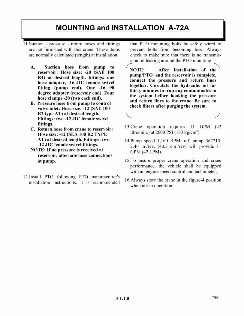
11.Suction - pressure - return hoses and fittingsare not furnished with this crane. These itemsare normally calculated (length) at installation.
A. Suction hose from pump toreservoir: Hose size: -20 (SAE 100R4) at desired length. fittings: onehose adapter, -16 JIC female swivelfitting (pump end). One -16 90degree adapter (reservoir end). Fourhose clamps -20 (two each end).
B. Pressure hose from pump to controlvalve inlet: Hose size: -12 (SAE 100R2 type AT) at desired length.Fittings: two -12 JIC female swivelfittings.
C. Return hose from crane to reservoir:Hose size: -12 (SEA 100 R2 TYPEAT) at desired length. Fittings: two-12 JIC female swivel fittings.
NOTE: If no pressure is received atreservoir, alternate hose connectionsat pump.
12.Install PTO following PTO manufacturer'sinstallation instructions. it is recommended
that PTO mounting bolts be safely wired toprevent bolts from becoming lose. Alwayscheck to make sure that there is no transmis-sion oil leaking around the PTO mounting
NOTE: After installation of thepump/PTO and the reservoir is complete,connect the pressure and return linestogether. Circulate the hydraulic oil forthirty minutes to trap any contaminates inthe system before hooking the pressureand return lines to the crane. Be sure tocheck filters after purging the system.
13.Crane operation requires 11 GPM (42litre/min.) at 2600 PSI (183 kg/cm2).
14.Pump speed 1,160 RPM, ref. pump 367215,2.46 in3/rev. (40.3 cm3/rev) will provide 11GPM (42 LPM).
15.To insure proper crane operation and craneperformance, the vehicle shall be equippedwith an engine speed control and tachometer.
16.Always store the crane in the figure-4 positionwhen not in operation.
MOUNTING and INSTALLATION A-72A
3-1.1.0 7/96
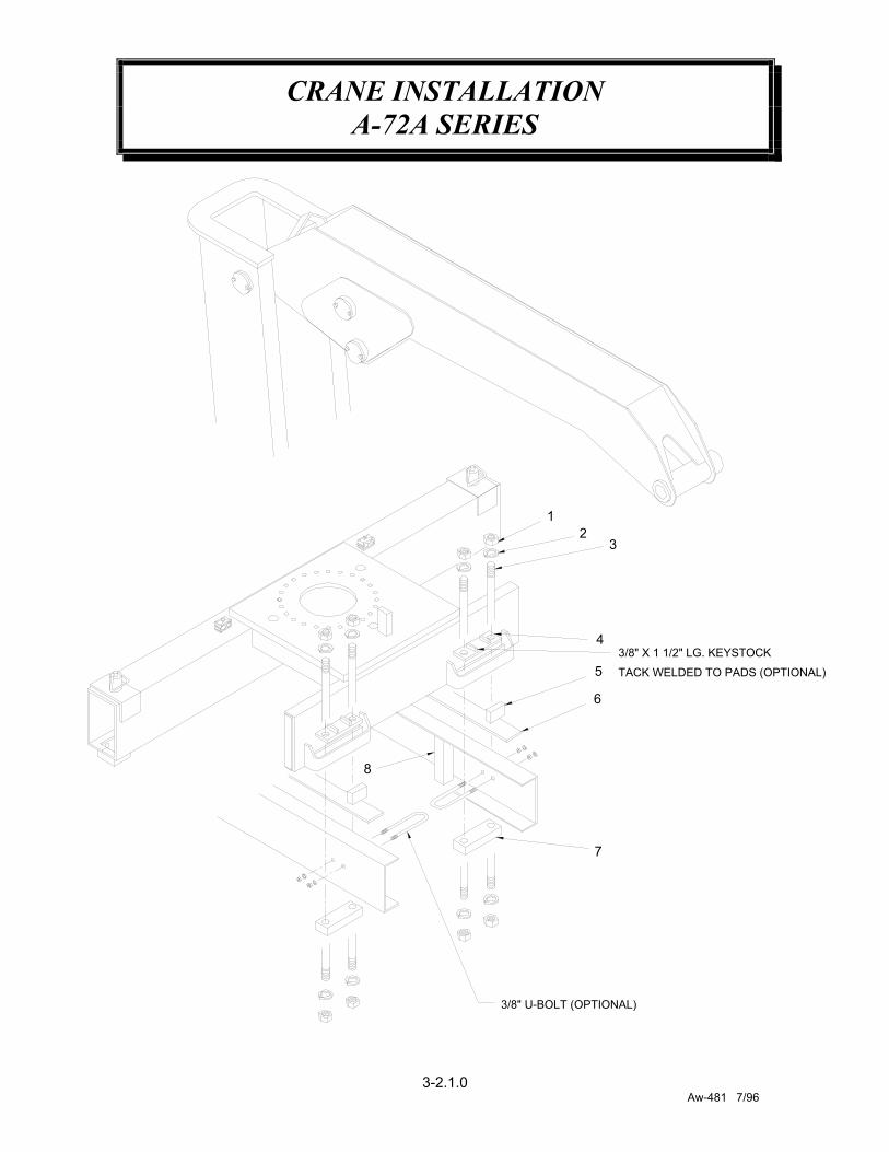
CRANE INSTALLATIONA-72A SERIES
3-2.1.0Aw-481 7/96
3/8" U-BOLT (OPTIONAL)
8
7
3/8" X 1 1/2" LG. KEYSTOCK
TACK WELDED TO PADS (OPTIONAL)
6
5
4
3
12

CRANE INSTALLATIONA-72A SERIES
3-2.2.0Aw-481 7/96
ITEM NO. QTY. PART NO. DESCRIPTION1 16 367183 NUT2 16 022300 LOCKWASHER3 8 367182 BOLT4 4 368087 TOP MOUNTING PAD5 4 800299-007 END TAB6 2 800265-007 WEAR PLATE7 4 368088 BOTTOM MOUNTING PAD8 4 800096-010 FRAME SPACER
Once crane has been mounted, the unitmust be checked for stability inaccordance with ANSI/SAE J765. Unitmust be stable with an 85% tippingfactor (i.e., when lifting capacity load theunit is at 85% of tipping or less).
1 Set up and test on firm level ground.
2 Chock rear wheels, engage emergencybrake, place gear selector in neutral.Press clutch and PTO knob in gear,release clutch and set throttle controlto proper engine speed. Always useoutriggers from the crane to theground. Be sure outriggers are in firmcontact with ground and areadequately positioned with unit levelside to side.
3 To stability check the crane assemble aload 118% of the capacity at thelongest hydraulic reach, start withboom extension(s) retracted andboom(s) horizontal, raise load 6"-8"inches off ground. Slowly extend the hydraulic extension until the loadreaches full extension. Once fullhydraulic extension is reached theassembled load shall be rotated either180 or 360 degrees around vehicle
depending upon stability arearequired.
4 Unit is considered stable when theassembled load moment acting tooverturn the unit is equal to themaximum moment of the unit avail-able to resist overturning. If unit is notstable, counter weighting will have tobe added to bring the unit into a stablecondition. A decal must be added todefine areas of full stability if the unitis not 360° stable.
5 Minimum chassis requirements do notensure stability. Actual stabilityratings can only be determined frominitial start-up and testing to deter-mine stability. If adding counterweight to the vehicle, it is most effec-tive when added as close to the craneas possible. After adding counterweight, the unit must be checked againfor stability to ensure the addedcounter weight is adequate.
6 Some cranes are equipped with anoverload protection system. It may benecessary to temporarily re-adjustoverload to allow for stability testing.Remember to always keep assembledload 6-8 inches off ground.
STABILITY CHECK
A50A Stable R11/943-3.0.0
1 Make sure all crane operating personnelhave thoroughly read and understood theinformation contained in this manual. Craneto be operated by qualified personnel only.
2 A routine daily inspection of the craneshould be mandatory before each operatingday. Any defects should be correctedimmediately and before operating the crane.
3 At a job site the vehicle should be positionedso that the crane can adequately reach theload within the rated capacity (centerline ofrotation to hook) of the crane. Job siteshould be checked for any hazards whichmight create an unsafe situation for theoperator; such as any overhead electricallines, underground electrical lines, anyelectrical source (s), soft or uneven ground,and any unauthorized personnel who mightenter the job site. When cross grade parkingis necessary, restrict the load to compensatefor the increased tipping risk of the vehicle.
WARNING: DO NOT EXCEED ENGINESPEED NECESSARY TO MEET PUMPRPM REQUIREMENT; POSSIBLEDAMAGE MAY RESULT.
4 Keep vehicle as level as possible duringoperation.
5 Chock rear wheels, engage emergency brake,place gear selector in neutral, press clutchand PTO knob in gear, release clutch and setthrottle control to proper engine speed.Extend outriggers to their maximum outposition. Always use outriggers from thecrane to the ground. Be sure outriggers arein firm contact with the ground and areadequately positioned.
6 When unstowing knuckleboom crane, firstbegin by retracting outer boom cylinder,which raises the outer boom up in the rampand purges any air out of the outer boomcylinder. Extend lift cylinder to raise innerboom. Once inner boom is clear of the base,crane can be rotated into a work readyposition. Always raise inner boom up beforerotating.
7 Always observe safe and practical operatingpractices to avoid possible accidents. Referto safety tips and precautions.
8 After completing lifting operations, returnthe booms to the figure-4 position for travel.When stowing, begin by retracting theextension cylinder. Retract outer boomcylinder. Rotate crane into position byaligning up the rotation arrows on therotation bearing and base plate. Retract liftcylinder to lower inner boom into thefigure-4 position. Always stand on theopposite side of the inner boom whenstowing and unstowing.
9 Return outriggers to the stowed position.Make sure they are pinned in place fortravel.
10 Check job site for any tools or equipmentnot stored. Store all wheel chocks.
11 Press clutch and disengage PTO. Releasethrottle control and emergency brake.
12 Report any unusual occurrence during craneoperation that may indicate requiredmaintenance or repair.
OPERATION OF UNIT
4-1.0.0 R7/96

OPERATORS
1 Crane operation shall be limited to personnel with thefollowing minimum qualifications:A. designated persons B. trainees under the direct supervision of a
designated person C. maintenance and test personnel (when it is
necessary in the performance of their duties) D. inspectors (crane).
2 No one other than the personnel specified above shallenter the operating area of a crane with the exceptionof persons such as oilers, supervisors, and thosespecified persons authorized by supervisors whoseduties require them to do so and then only in theperformance of their duties and with the knowledgeof the operator or other persons.
QUALIFICATIONS FOR OPERATORS
3 Operators shall be required by the employer to pass apractical operating examination. Qualifications shallbe limited to the specific type of equipment for whichexamined.
4 Operators and operator trainees shall meet thefollowing physical qualifications:A. Vision of at least 20/30 snellen in one eye and
20/50 in the other, with or without correctivelenses.
B. Ability to distinguish colors, regardless ofposition, if colors differentiation is required foroperation.
C. Adequate hearing with or without hearing aid forthe specific operation.
5 Evidence of physical defects or emotional instabilitywhich render a hazard to operator or others, which inthe opinion of the examiner could interfere with theoperator's performance may be sufficient cause fordisqualification. In such cases, specialized clinical ormedical judgment and tests may be required.
6 Evidence that the operator is subject to seizures orloss of physical control shall be sufficient reason fordisqualification. Specialized medical tests may berequired to determine these conditions.
7 Operators and operator trainees should have normaldepth perception, coordination, and no tendencies todizziness or similar undesirable characteristics.
8 In addition to the above listed requirements, theoperator shall:A. Demonstrate the ability to comprehend and
interpret all labels, operator's manuals, safetycodes and other information pertinent to correctcrane operations.
B. Possess knowledge of emergency procedures andimplementation of same.
C. Demonstrate to the employer the ability tooperate the specific type of equipment.
D. Be familiar with the applicable safety regulations.
E. Understand responsibility for maintenancerequirements of crane.
F. Be thoroughly familiar with the crane and itscontrol functions.
G. Understand the operating procedures as outlinedby the manufacturer.
CONDUCT OF OPERATORS
9 The operator shall not engage in any practice whichwill divert his attention while actually operating thecrane.
10 Each operator shall be responsible for thoseoperations under the operator's direct control.Whenever there is any doubt as to safety, theoperator shall consult with the supervisor beforehandling the loads.
11 The operator should not leave a suspended loadunattended unless specific precautions have beeninstituted and are in place.
12 If there is a warning sign on the switch or enginestarting controls, the operator shall not close theswitch or start the engine until the warning sign hasbeen removed by the appointed person.
13 Before closing the switch or starting the engine, theoperator shall see that all controls are in the "OFF"or neutral position and all personnel are in the clear.
14 If power fails during operation, the operator shall:A. move power controls to the "OFF" or neutral
position. B. land the suspended load and boom, if practical.
15 The operator shall be familiar with the equipmentand its proper care. If adjustments or repairs arenecessary, the operator shall report the same
QUALIFICATIONS FOR AND CONDUCT OF OPERATORSAND OPERATING PRACTICES
7/964-2.0.0
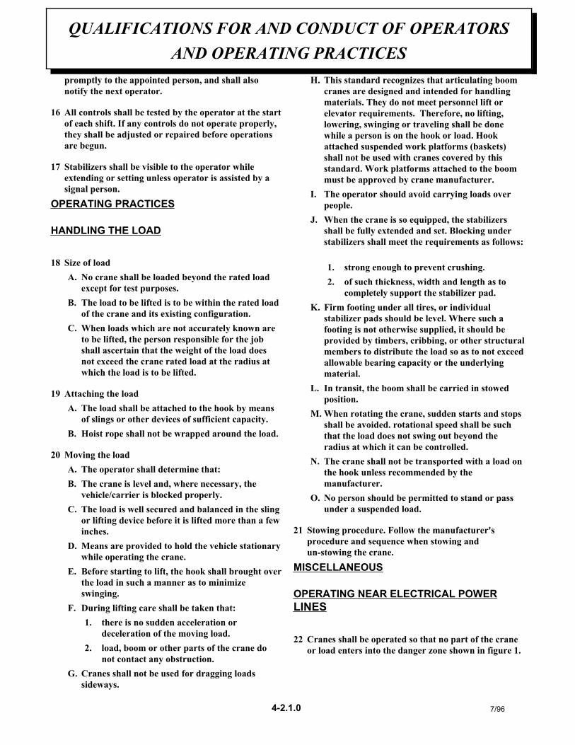
promptly to the appointed person, and shall alsonotify the next operator.
16 All controls shall be tested by the operator at the startof each shift. If any controls do not operate properly,they shall be adjusted or repaired before operationsare begun.
17 Stabilizers shall be visible to the operator whileextending or setting unless operator is assisted by asignal person.
OPERATING PRACTICES
HANDLING THE LOAD
18 Size of loadA. No crane shall be loaded beyond the rated load
except for test purposes. B. The load to be lifted is to be within the rated load
of the crane and its existing configuration. C. When loads which are not accurately known are
to be lifted, the person responsible for the jobshall ascertain that the weight of the load doesnot exceed the crane rated load at the radius atwhich the load is to be lifted.
19 Attaching the loadA. The load shall be attached to the hook by means
of slings or other devices of sufficient capacity.B. Hoist rope shall not be wrapped around the load.
20 Moving the loadA. The operator shall determine that:B. The crane is level and, where necessary, the
vehicle/carrier is blocked properly. C. The load is well secured and balanced in the sling
or lifting device before it is lifted more than a fewinches.
D. Means are provided to hold the vehicle stationarywhile operating the crane.
E. Before starting to lift, the hook shall brought overthe load in such a manner as to minimizeswinging.
F. During lifting care shall be taken that: 1. there is no sudden acceleration or
deceleration of the moving load. 2. load, boom or other parts of the crane do
not contact any obstruction. G. Cranes shall not be used for dragging loads
sideways.
H. This standard recognizes that articulating boomcranes are designed and intended for handlingmaterials. They do not meet personnel lift orelevator requirements. Therefore, no lifting,lowering, swinging or traveling shall be donewhile a person is on the hook or load. Hookattached suspended work platforms (baskets)shall not be used with cranes covered by thisstandard. Work platforms attached to the boommust be approved by crane manufacturer.
I. The operator should avoid carrying loads overpeople.
J. When the crane is so equipped, the stabilizersshall be fully extended and set. Blocking understabilizers shall meet the requirements as follows:
1. strong enough to prevent crushing. 2. of such thickness, width and length as to
completely support the stabilizer pad. K. Firm footing under all tires, or individual
stabilizer pads should be level. Where such afooting is not otherwise supplied, it should beprovided by timbers, cribbing, or other structuralmembers to distribute the load so as to not exceedallowable bearing capacity or the underlyingmaterial.
L. In transit, the boom shall be carried in stowedposition.
M. When rotating the crane, sudden starts and stopsshall be avoided. rotational speed shall be suchthat the load does not swing out beyond theradius at which it can be controlled.
N. The crane shall not be transported with a load onthe hook unless recommended by themanufacturer.
O. No person should be permitted to stand or passunder a suspended load.
21 Stowing procedure. Follow the manufacturer'sprocedure and sequence when stowing andun-stowing the crane.
MISCELLANEOUS
OPERATING NEAR ELECTRICAL POWERLINES
22 Cranes shall be operated so that no part of the craneor load enters into the danger zone shown in figure 1.
QUALIFICATIONS FOR AND CONDUCT OF OPERATORSAND OPERATING PRACTICES
7/964-2.1.0
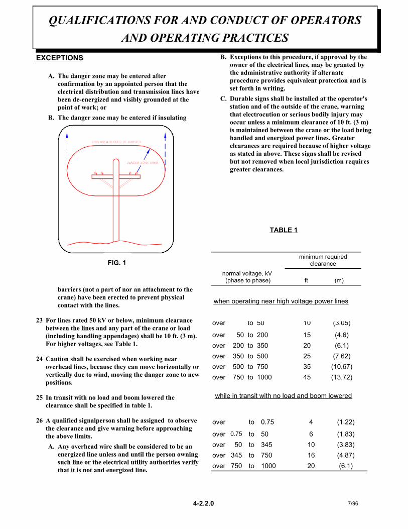
EXCEPTIONS
A. The danger zone may be entered afterconfirmation by an appointed person that theelectrical distribution and transmission lines havebeen de-energized and visibly grounded at thepoint of work; or
B. The danger zone may be entered if insulating
barriers (not a part of nor an attachment to thecrane) have been erected to prevent physicalcontact with the lines.
23 For lines rated 50 kV or below, minimum clearancebetween the lines and any part of the crane or load(including handling appendages) shall be 10 ft. (3 m).For higher voltages, see Table 1.
24 Caution shall be exercised when working nearoverhead lines, because they can move horizontally orvertically due to wind, moving the danger zone to newpositions.
25 In transit with no load and boom lowered theclearance shall be specified in table 1.
26 A qualified signalperson shall be assigned to observethe clearance and give warning before approachingthe above limits.A. Any overhead wire shall be considered to be an
energized line unless and until the person owningsuch line or the electrical utility authorities verifythat it is not and energized line.
B. Exceptions to this procedure, if approved by theowner of the electrical lines, may be granted bythe administrative authority if alternateprocedure provides equivalent protection and isset forth in writing.
C. Durable signs shall be installed at the operator'sstation and of the outside of the crane, warningthat electrocution or serious bodily injury mayoccur unless a minimum clearance of 10 ft. (3 m)is maintained between the crane or the load beinghandled and energized power lines. Greaterclearances are required because of higher voltageas stated in above. These signs shall be revisedbut not removed when local jurisdiction requiresgreater clearances.
QUALIFICATIONS FOR AND CONDUCT OF OPERATORSAND OPERATING PRACTICES
7/964-2.2.0
TABLE 1
(13.72)451000to750over(10.67)35750to500over(7.62)25500to350over(6.1)20350to200over(4.6)15200to50over
(3.05)1050toover
when operating near high voltage power lines
ft (m)
normal voltage, kV (phase to phase)
minimum requiredclearance
(6.1)201000to750over(4.87)16750to345over(3.83)10345to50over(1.83)650to0.75over
(1.22)40.75toover
while in transit with no load and boom lowered
FIG. 1
INSPECTION CLASSIFICATION
1 Initial inspection. Prior to initial use, all new,altered, modified or extensively repaired cranesshall be inspected by a designated person toinsure compliance with provisions of thisstandard.
2 Regular inspection. Inspection procedure forcranes in regular service is divided into twogeneral classifications based upon the intervals atwhich inspection should be performed. Theintervals in turn are dependent upon the natureof the components of the crane and the degree oftheir exposure to wear, deterioration, ormalfunction. The two general classifications areherein designated as "frequent" and "periodic"with respective intervals between inspections asdefined below.
A. frequent inspection - daily to monthlyintervals.
B. periodic inspection - one to twelve intervals,or as specifically recommended by themanufacturer.
FREQUENT INSPECTION
3 Inspection shall be performed by designatedpersonnel.
A. control mechanisms for maladjustment inter-fering with proper operation - daily, whenused;
B. control mechanisms for excessive wear ofcomponents and contamination by lubricantsor other foreign matter;
C. safety devices for malfunction;
D. all hydraulic hoses, particularly those whichflex in normal operation of crane functions,should be visually inspected once everyworking day, when used;
E. hooks and latches for deformation, chemicaldamage, cracks, and wear. Refer toANSI/ASME B30.10;
F. rope reeving for compliance with cranemanufacturer's specifications, if optionalwinch is used;
G. electrical apparatus for malfunctioning, signsof excessive deterioration, dirt and moistureaccumulation;
H. hydraulic system for proper oil level andleaks daily;
I. tires for recommended inflation pressure,cuts and loose wheel nuts;
J. connecting pins and locking device for wearand damage;
PERIODIC INSPECTION
4 Deformed, cracked or corroded members in thecrane structure and carrier;
5 Loose bolts, particularly mounting bolts;
6 Cracked or worn sheaves and drums;
7 Worn, cracked, or distorted parts such as pins,bearings, shafts, gears, rollers and devices;
8 Excessive wear on brake and clutch system partsand lining;
9 Crane hooks inspected for cracks;
10 Travel steering, braking, and locking devices, formalfunction;
11 Excessively worn or damaged tires;
12 Hydraulic and pneumatic hose, fittings, andtubing inspection;
A. evidence of leakage at the surface of the flexi-ble hose or its junction with metal andcoupling;
B. blistering, or abnormal deformation to theouter covering of the hydraulic or pneumatichose;
7/96
INSPECTION, TESTING AND MAINTENANCE
GENERAL
5-1.0.0
C. leakage at threaded or clamped joints thatcannot be eliminated by normal tightening orrecommended procedures;
D. evidence or excessive abrasion or scrubbingon the outer surface of a hose, rigid tube, orfitting. Means shall be taken to eliminate theinterference of elements in contact or other-wise protect the components.
13 Hydraulic and pneumatic pumps and motorsinspection
A. loose bolts or fasteners;
B. leaks at joints between sections;
C. shaft seal leaks;
D. unusual noises or vibrations;
E. loss of operating speed;
F. excessive heating of the fluid;
G. loss of pressure.
14 Hydraulic and pneumatic valves inspection
A. cracks in valve housing;
B. improper return of spool to neutral position;
C. leaks at spools or joints;
D. sticking spools;
E. failure of relief valves to attain or maintaincorrect pressure setting;
F. relief valve pressure shall be checked asspecified by the manufacturers.
15 Hydraulic and pneumatic cylinders inspection
A. drifting caused by fluid leaking acrosspiston;
B. rod seals leaking
C. leaks at welding joints
D. scored, nicked, or dented cylinder rods;
E. damaged case (barrel);
F. loose or deformed rod eyes or connectingjoints.
16 Hydraulic filters. Evidence of rubber particles onthe filter elements may indicate hose, "O" ring,or other rubber component deterioration. Metalchips or pieces on the filter may denote failure inpumps, motors, or cylinders. Further checkingwill be necessary to determine origin of theproblem before corrective action can be taken.
17 Labels are to be in place and legible.
CRANES NOT IN REGULAR USE
18 A crane which has been idle for a period of overone month or more, but not less than six months,shall be given an inspection conforming with theinitial-regular- frequent inspections.
19 A crane which has been idle for a period of oversix months shall be given a complete inspectionconforming with the initial-regular-frequentinspection requirements.
INSPECTION RECORDS
20 Dated records for periodic inspection should bemade on critical items such as brakes, cranehooks, rope, hydraulic and pneumatic cylinders,and hydraulic and pneumatic relief pressurevalves. Records should be kept available to anappointed person.
OPERATIONAL TESTS
21 Prior to initial use, all new, altered, modified, orextensively repaired cranes shall be tested forcompliance with the operational requirements ofthis section, including functions such as thefollowing:
A. load lifting and lowering mechanisms;
B. boom lifting and lowering mechanisms;
C. boom extension and retraction mechanisms;
D. swing mechanisms;
E. safety devices;
F. operating controls comply with appropriatefunction labels.
7/965-1.1.0
Operational crane test results shall be madeavailable to an appointed person.
RATED TEST LOADPrior to initial use, altered, modified, orextensively repaired cranes shall be loadtested by or under the direction of anappointed person.
22 Test loads shall not exceed 110% of the manufac-turer's load ratings.
23 Written reports shall be maintained showing testprocedures and confirming the adequacy ofrepairs.
MAINTENANCE
PREVENTIVE MAINTENANCE
24 Before adjustment and repairs are started on acrane, the following precautions shall be taken asapplicable:
A. crane placed where it will cause the leastinterference with other equipment or opera-tions;
B. all controls at the "off" position;
C. starting means rendered inoperative;
D. boom lowered to the ground if possible orotherwise secured against dropping;
E. relieve hydraulic oil pressure from allhydraulic circuits before loosening or remov-ing hydraulic components.
25 Warning or "OUT OF ORDER" signs shall beplaced on the crane controls.
26 After adjustments and repairs have been made,the crane shall not be returned to service until allguards have been reinstalled, trapped airremoved from hydraulic system (if required),safety devices reactivated, and maintenanceequipment removed.
ADJUSTMENTS AND REPAIRS
27 Any hazardous conditions disclosed by theinspection requirements shall be corrected beforeoperation of crane is resumed, Adjustments and
repairs shall be done only by designatedpersonnel.
28 Adjustments shall be maintained to assurecorrect functioning of components, The followingare examples:
A. functional operating mechanism;
B. safety devices;
C. control systems;
29 Repairs or replacements shall be provided asneeded for operation.
The following are examples:
A. critical parts of functional operating mecha-nisms which are cracked, broken, corroded,bent, or excessively worn;
B. critical parts of the crane structure which arecracked, bent, broken, or excessivelycorroded;
C. crane hooks showing cracks, damage, orcorrosion shall be taken out of service.Repairs by welding are not recommended.
30 Instructions shall be provided by the manufac-turer for the removal of air from hydrauliccircuits.
LUBRICATIONAll moving parts of the crane, for whichlubrication is specified, should be regularlylubricated per the manufacturer'srecommendations and procedures.
ROPE INSPECTION
31 Frequent Inspection
A. All running ropes in service should bevisually inspected once each working day. Avisual inspection shall consist of observationof all rope which can be in use during thedays operations. These visual observationsshould be considered with discovering grossdamage such as listed below, which may bean immediate hazard;
1. distortion of the rope such as kinking,crushing, un-stranding, birdcaging, mainstrand displacement, or core protrusion.
7/965-1.2.0
Loss of rope diameter in a short length orunevenness of outer strands should bereplaced;
2. general corrosion; 3. broken or cut strands; 4. number, distribution and type of visible
broken wires. When such damage isdiscovered, the rope shall either beremoved from service or given asinspection.
B. Care shall be taken when inspecting sectionsof rapid deterioration such as flange points,crossover points, and repetitive pickup pointson drums.
32 Periodic inspection
A. the inspection frequency shall be determinedby a qualified person and shall be based onsuch factors as:
1. expected rope life as determined byexperience on the particular installation orsimilar installations;
2. severity of environment; 3. percentage of capacity lifts; 4. frequency rates of operation; 5. exposure to shock loads;
Inspection need not be at equal calendarintervals and should be more frequent as therope approaches the end of it's service life.This inspection shall be made at leastannually.
B. Periodic inspection shall be performed by adesignated person. This inspection shallcover the entire length of the rope. Only thesurface wires need be inspected. No attemptshould be made to open the rope. Anydeterioration results in appreciable loss oforiginal strength, such as described below,shall be noted and determination made as towhether use of the rope would constitute ahazard: points listed above reduction of ropediameter below nominal diameter due to lossof core support, internal or external corro-sion, or wear of outside wires; severelycorroded, cracked, bent, worn or improperlyapplied connections;
C. Care shall be taken when inspecting sectionssubject to rapid deterioration such as thefollowing:
1. sections in contact with saddles, equalizersheaves, or other sheaves where ropetravel is limited;
2. sections of the rope at or near terminalends where corroded or broken wires mayprotrude.
ROPE REPLACEMENT
33 No precise rules can be given for determinationof the exact time for replacement of rope, sincemany variable factors are involved.
Continued use in this respect depends upongood judgement by a designated person inevaluating remaining strength in a used ropeafter allowance for deterioration disclosed byinspection. Continued rope operation dependsupon this remaining strength.
34 Conditions such as the following shall be reasonfor questioning continued use of the rope orincreasing the frequency of inspection:
A. in running ropes, six randomly distributedbroken wires in one lay or three brokenwires in one strand in one lay:
B. one outer wire broken at the contact pointwith the core of the rope structure andprotrudes or loops out of the rope structure.Additional inspection of this section isrequired.
C. wear of one third of the original diameter ofthe outside individual wire.
D. kinking, crushing, birdcaging, or any otherdamage resulting in distortion of the ropestructure.
E. evidence of any heat damage from any cause.
F. reduction from nominal diameter of morethan 1/64 in. (0.4mm) for diameters up toand including 5/16 in. (8 mm), 1/32 in. (0.8mm) for diameter 3/8 in. (9.5 mm) to andincluding 1/2 in. (13 mm), 3/64 in. (1.2 mm)for diameter 9/16 in. (14.5 mm) to andincluding 3/4 in. (19 mm). 1/16 in. (1.6 mm)for diameter 7/8 in. (22 mm) to and including
7/965-1.3.0
1 1/8 in. (29 mm), 3/32 in. (2.4 mm) fordiameters 1 1/4 in. (32 mm) to and including1 1/2 in. (38 mm).
G. In standing ropes, more than two brokenwires in one lay in sections beyond endconnections or more than one broken wire atan end connection.
H. Replacement rope shall have a strengthrating at least as great as the original ropefurnished or recommended by the cranemanufacturer. Any deviation from the origi-nal size, grade, or construction shall be speci-fied by a rope manufacturer, or a qualifiedperson.
35 Rope not in regular use: all rope which has beenidle for a period of a month or more due toshutdown or storage of a crane on which it isinstalled, shall be given and inspection in accor-dance with above information before it is placedin service. This inspection shall be for all types ofdeterioration and shall be performed by a quali-fied person.
36 Inspection records
A. frequent inspection- no records required
B. periodic inspections- in order to establishdata as a basis for judging the proper timefor replacement, a dated report condition ateach periodic inspection should be kept onfile. This report shall cover points of deterio-ration listed above.
ROPE MAINTENANCE
37 Rope should be stored to prevent damage ordeterioration.
38 Unreeling or uncoiling of rope shall be done asrecommended by the rope manufacturer andwith care to avoid kinking or inducing twist.
39 Before cutting a rope, seizing shall be placed oneach side of the place where the rope is to be cutto prevent unlaying of the strands. Onpre-formed rope, one seizing on each side of thecut is required. On non-preformed ropes of 7/8in. (22 mm) diameter or smaller, two seizings oneach side of the cut are required, and fornon-preformed rope 1 in. (25 mm) diameter orlarger, three seizings on each side of the cut arerequired.
40 During installation care should be exercised toavoid dragging of the rope in the dirt or aroundobjects which will scrape, nick crush or inducesharp bends in it.
41 Rope should be maintained in a well-lubricatedcondition. It is important that lubricant appliedas a part of a maintenance program shall becompatible with the original lubricant and to thisend the rope manufacturer should be consulted.Lubricant applied shall be the type which doesnot hinder visual inspection. Those sections ofrope which are located over sheaves or otherwisehidden during inspection and maintenanceprocedures require special attention when lubri-cating rope. The object of rope lubrication is toreduce internal friction and to prevent corrosion.
42 When an operating rope shows greater wear orwell defined localized areas than on the remain-der of the rope, rope life can be extended in caseswhere a section at the worn end, and thus shift-ing the wear to different areas of the rope.
7/965-1.4.0

NOTES
ROTATION BEARING RACE
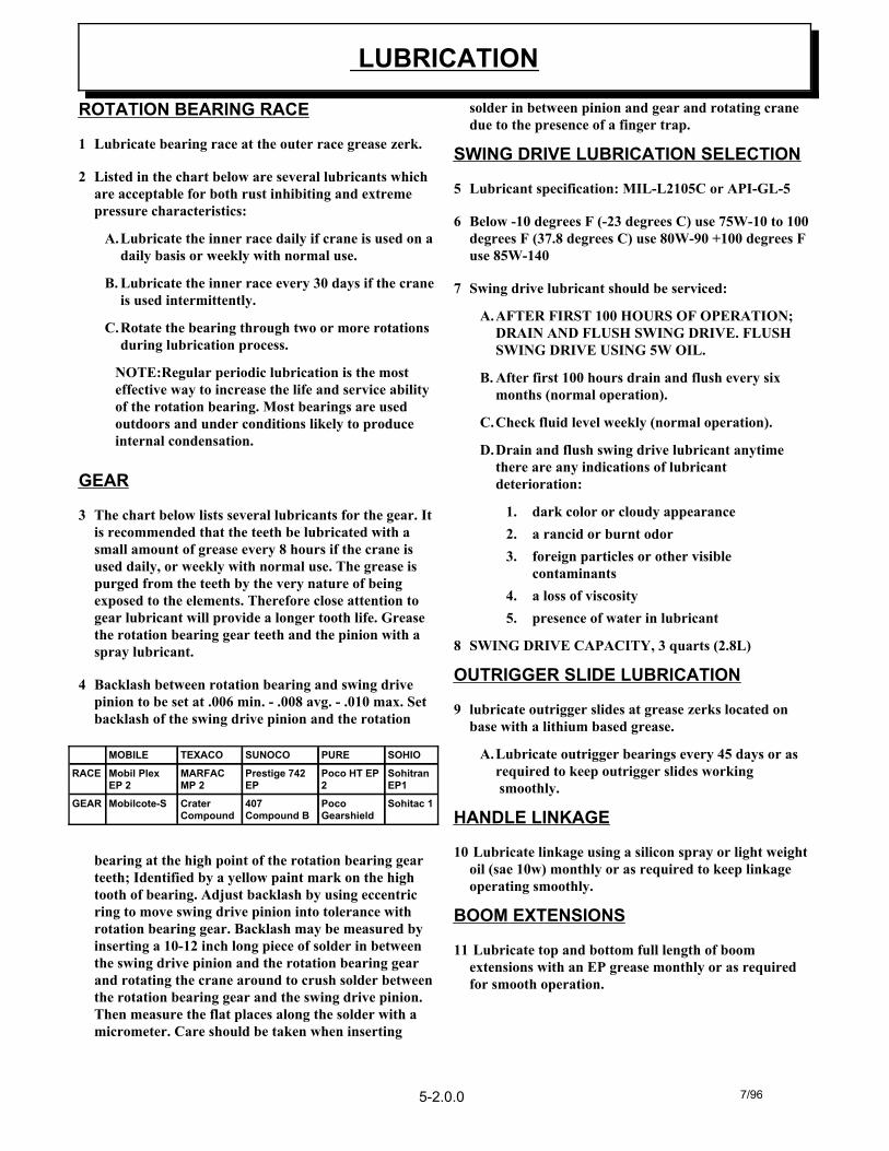
1 Lubricate bearing race at the outer race grease zerk.
2 Listed in the chart below are several lubricants whichare acceptable for both rust inhibiting and extremepressure characteristics:
A.Lubricate the inner race daily if crane is used on adaily basis or weekly with normal use.
B. Lubricate the inner race every 30 days if the craneis used intermittently.
C.Rotate the bearing through two or more rotationsduring lubrication process.
NOTE:Regular periodic lubrication is the mosteffective way to increase the life and service abilityof the rotation bearing. Most bearings are usedoutdoors and under conditions likely to produceinternal condensation.
GEAR
3 The chart below lists several lubricants for the gear. Itis recommended that the teeth be lubricated with asmall amount of grease every 8 hours if the crane isused daily, or weekly with normal use. The grease ispurged from the teeth by the very nature of beingexposed to the elements. Therefore close attention togear lubricant will provide a longer tooth life. Greasethe rotation bearing gear teeth and the pinion with aspray lubricant.
4 Backlash between rotation bearing and swing drivepinion to be set at .006 min. - .008 avg. - .010 max. Setbacklash of the swing drive pinion and the rotation
bearing at the high point of the rotation bearing gearteeth; Identified by a yellow paint mark on the hightooth of bearing. Adjust backlash by using eccentricring to move swing drive pinion into tolerance withrotation bearing gear. Backlash may be measured byinserting a 10-12 inch long piece of solder in betweenthe swing drive pinion and the rotation bearing gearand rotating the crane around to crush solder betweenthe rotation bearing gear and the swing drive pinion.Then measure the flat places along the solder with amicrometer. Care should be taken when inserting
solder in between pinion and gear and rotating cranedue to the presence of a finger trap.
SWING DRIVE LUBRICATION SELECTION
5 Lubricant specification: MIL-L2105C or API-GL-5
6 Below -10 degrees F (-23 degrees C) use 75W-10 to 100degrees F (37.8 degrees C) use 80W-90 +100 degrees Fuse 85W-140
7 Swing drive lubricant should be serviced:
A.AFTER FIRST 100 HOURS OF OPERATION;DRAIN AND FLUSH SWING DRIVE. FLUSHSWING DRIVE USING 5W OIL.
B. After first 100 hours drain and flush every sixmonths (normal operation).
C.Check fluid level weekly (normal operation).
D.Drain and flush swing drive lubricant anytimethere are any indications of lubricantdeterioration:
1. dark color or cloudy appearance2. a rancid or burnt odor3. foreign particles or other visible
contaminants4. a loss of viscosity5. presence of water in lubricant
8 SWING DRIVE CAPACITY, 3 quarts (2.8L)
OUTRIGGER SLIDE LUBRICATION
9 lubricate outrigger slides at grease zerks located onbase with a lithium based grease.
A.Lubricate outrigger bearings every 45 days or asrequired to keep outrigger slides working smoothly.
HANDLE LINKAGE
10 Lubricate linkage using a silicon spray or light weightoil (sae 10w) monthly or as required to keep linkageoperating smoothly.
BOOM EXTENSIONS
11 Lubricate top and bottom full length of boomextensions with an EP grease monthly or as requiredfor smooth operation.
LUBRICATION
Sohitac 1PocoGearshield
407Compound B
CraterCompound
Mobilcote-SGEAR
SohitranEP1
Poco HT EP2
Prestige 742EP
MARFACMP 2
Mobil Plex EP 2
RACE
SOHIOPURESUNOCOTEXACOMOBILE
7/965-2.0.0
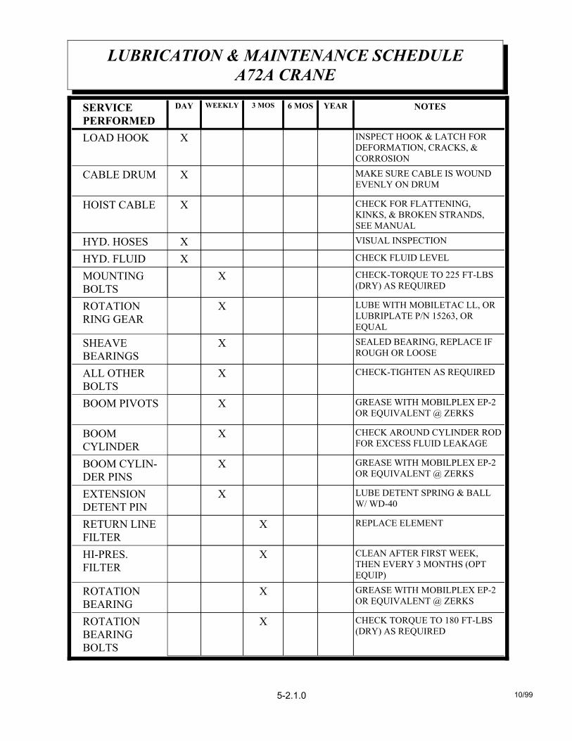
CHECK TORQUE TO 180 FT-LBS(DRY) AS REQUIRED
XROTATIONBEARING BOLTS
GREASE WITH MOBILPLEX EP-2OR EQUIVALENT @ ZERKS
XROTATIONBEARING
CLEAN AFTER FIRST WEEK,THEN EVERY 3 MONTHS (OPTEQUIP)
XHI-PRES.FILTER
REPLACE ELEMENTXRETURN LINEFILTER
LUBE DETENT SPRING & BALLW/ WD-40
XEXTENSIONDETENT PIN
GREASE WITH MOBILPLEX EP-2OR EQUIVALENT @ ZERKS
XBOOM CYLIN-DER PINS
CHECK AROUND CYLINDER RODFOR EXCESS FLUID LEAKAGE
XBOOMCYLINDER
GREASE WITH MOBILPLEX EP-2OR EQUIVALENT @ ZERKS
XBOOM PIVOTS
CHECK-TIGHTEN AS REQUIREDXALL OTHERBOLTS
SEALED BEARING, REPLACE IFROUGH OR LOOSE
XSHEAVEBEARINGS
LUBE WITH MOBILETAC LL, ORLUBRIPLATE P/N 15263, OREQUAL
XROTATIONRING GEAR
CHECK-TORQUE TO 225 FT-LBS(DRY) AS REQUIRED
XMOUNTINGBOLTS
CHECK FLUID LEVELXHYD. FLUID
VISUAL INSPECTIONXHYD. HOSES
CHECK FOR FLATTENING,KINKS, & BROKEN STRANDS,SEE MANUAL
XHOIST CABLE
MAKE SURE CABLE IS WOUNDEVENLY ON DRUM
XCABLE DRUM
INSPECT HOOK & LATCH FORDEFORMATION, CRACKS, &CORROSION
XLOAD HOOK
NOTESYEAR6 MOS3 MOSWEEKLYDAYSERVICE PERFORMED
10/99
LUBRICATION & MAINTENANCE SCHEDULEA72A CRANE
5-2.1.0
1) OWNER'S MANUAL 2) OSHA SECTION 1910.180 3) ANSI B30.5-1989
FORADDITIONAL INFORMATION
SEE:
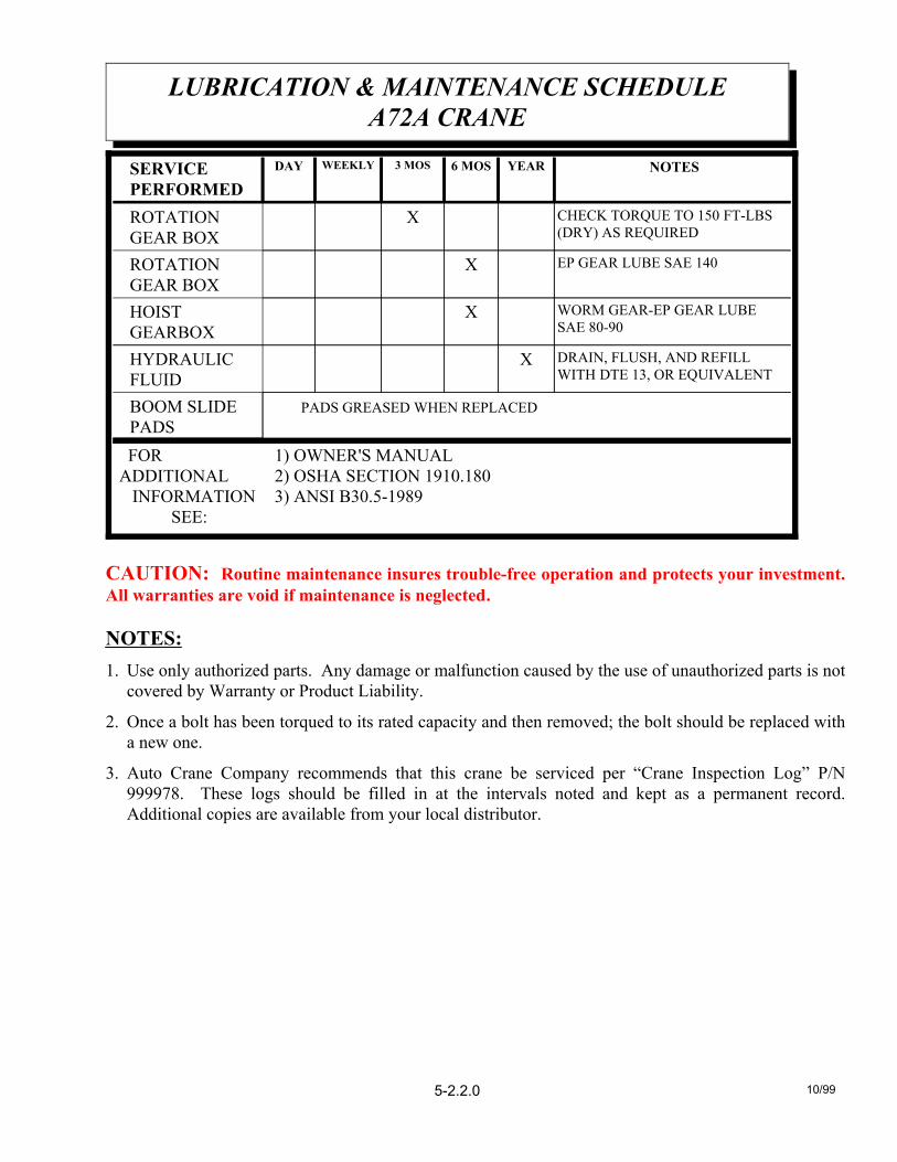
PADS GREASED WHEN REPLACED BOOM SLIDEPADS
DRAIN, FLUSH, AND REFILLWITH DTE 13, OR EQUIVALENT
XHYDRAULICFLUID
WORM GEAR-EP GEAR LUBESAE 80-90
XHOISTGEARBOX
EP GEAR LUBE SAE 140XROTATIONGEAR BOX
CHECK TORQUE TO 150 FT-LBS(DRY) AS REQUIRED
XROTATIONGEAR BOX
NOTESYEAR6 MOS3 MOSWEEKLYDAYSERVICE PERFORMED
CAUTION: Routine maintenance insures trouble-free operation and protects your investment.All warranties are void if maintenance is neglected.
NOTES:1. Use only authorized parts. Any damage or malfunction caused by the use of unauthorized parts is not
covered by Warranty or Product Liability.
2. Once a bolt has been torqued to its rated capacity and then removed; the bolt should be replaced witha new one.
3. Auto Crane Company recommends that this crane be serviced per “Crane Inspection Log” P/N999978. These logs should be filled in at the intervals noted and kept as a permanent record.Additional copies are available from your local distributor.
10/99
LUBRICATION & MAINTENANCE SCHEDULEA72A CRANE
5-2.2.0

NOTES
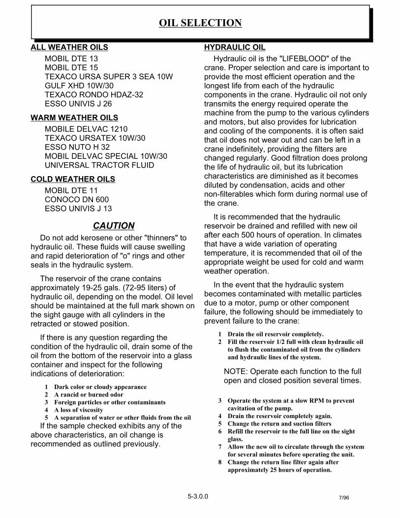
ALL WEATHER OILSMOBIL DTE 13 MOBIL DTE 15 TEXACO URSA SUPER 3 SEA 10W GULF XHD 10W/30 TEXACO RONDO HDAZ-32 ESSO UNIVIS J 26
WARM WEATHER OILSMOBILE DELVAC 1210 TEXACO URSATEX 10W/30 ESSO NUTO H 32 MOBIL DELVAC SPECIAL 10W/30UNIVERSAL TRACTOR FLUID
COLD WEATHER OILSMOBIL DTE 11 CONOCO DN 600 ESSO UNIVIS J 13
CAUTIONDo not add kerosene or other "thinners" to
hydraulic oil. These fluids will cause swellingand rapid deterioration of "o" rings and otherseals in the hydraulic system.
The reservoir of the crane containsapproximately 19-25 gals. (72-95 liters) ofhydraulic oil, depending on the model. Oil levelshould be maintained at the full mark shown onthe sight gauge with all cylinders in theretracted or stowed position.
If there is any question regarding thecondition of the hydraulic oil, drain some of theoil from the bottom of the reservoir into a glasscontainer and inspect for the followingindications of deterioration:
1 Dark color or cloudy appearance 2 A rancid or burned odor 3 Foreign particles or other contaminants 4 A loss of viscosity 5 A separation of water or other fluids from the oil
If the sample checked exhibits any of theabove characteristics, an oil change isrecommended as outlined previously.
HYDRAULIC OILHydraulic oil is the "LIFEBLOOD" of the
crane. Proper selection and care is important toprovide the most efficient operation and thelongest life from each of the hydrauliccomponents in the crane. Hydraulic oil not onlytransmits the energy required operate themachine from the pump to the various cylindersand motors, but also provides for lubricationand cooling of the components. it is often saidthat oil does not wear out and can be left in acrane indefinitely, providing the filters arechanged regularly. Good filtration does prolongthe life of hydraulic oil, but its lubricationcharacteristics are diminished as it becomesdiluted by condensation, acids and othernon-filterables which form during normal use ofthe crane.
It is recommended that the hydraulicreservoir be drained and refilled with new oilafter each 500 hours of operation. In climatesthat have a wide variation of operatingtemperature, it is recommended that oil of theappropriate weight be used for cold and warmweather operation.
In the event that the hydraulic systembecomes contaminated with metallic particlesdue to a motor, pump or other componentfailure, the following should be immediately toprevent failure to the crane:
1 Drain the oil reservoir completely. 2 Fill the reservoir 1/2 full with clean hydraulic oil
to flush the contaminated oil from the cylindersand hydraulic lines of the system.
NOTE: Operate each function to the fullopen and closed position several times.
3 Operate the system at a slow RPM to preventcavitation of the pump.
4 Drain the reservoir completely again.5 Change the return and suction filters6 Refill the reservoir to the full line on the sight
glass.7 Allow the new oil to circulate through the system
for several minutes before operating the unit.8 Change the return line filter again after
approximately 25 hours of operation.
OIL SELECTION
5-3.0.0 7/96
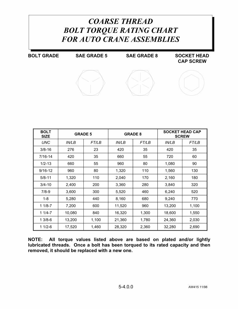
BOLT GRADE SAE GRADE 5 SAE GRADE 8 SOCKET HEAD CAP SCREW
NOTE: All torque values listed above are based on plated and/or lightlylubricated threads. Once a bolt has been torqued to its rated capacity and thenremoved, it should be replaced with a new one.
AW415 11/98
COARSE THREADBOLT TORQUE RATING CHART
FOR AUTO CRANE ASSEMBLIES
5-4.0.0
2,69032,2802,36028,3201,46017,5201 1/2-6
2,03024,3601,78021,3601,10013,2001 3/8-6
1,55018,6001,30016,32084010,0801 1/4-7
1,10013,20096011,5206007,2001 1/8-7
7709,2406808,1604405,2801-8
5206,2404605,5203003,6007/8-9
3203,8402803,3602002,4003/4-10
1802,1601702,0401101,3205/8-11
1301,5601101,320809609/16-12
901,08080960556601/2-13
6072055660354207/16-14
3542035420232763/8-16
FT/LBIN/LBFT/LBIN/LBFT/LBIN/LBUNC
SOCKET HEAD CAPSCREWGRADE 8GRADE 5BOLT
SIZE
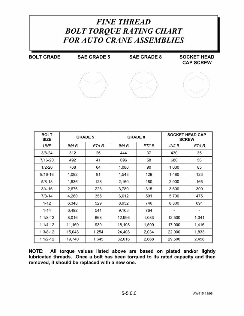
BOLT GRADE SAE GRADE 5 SAE GRADE 8 SOCKET HEAD CAP SCREW
NOTE: All torque values listed above are based on plated and/or lightlylubricated threads. Once a bolt has been torqued to its rated capacity and thenremoved, it should be replaced with a new one.
AW415 11/98
FINE THREADBOLT TORQUE RATING CHART
FOR AUTO CRANE ASSEMBLIES
5-5.0.0
2,45829,5002,66832,0161,64519,7401 1/2-12
1,83322,0002,03424,4081,25415,0481 3/8-12
1,41617,0001,50918,10893011,1601 1/4-12
1,04112,5001,08312,9966688,0161 1/8-12
--7649,1685416,4921-14
6918,3007468,9525296,3481-12
4755,7005016,0123554,2607/8-14
3003,6003153,7802232,6763/4-16
1662,0001802,1601281,5365/8-18
1231,4801291,548911,0929/16-18
851,030901,080647681/2-20
5668058696414927/16-20
3543037444263123/8-24
FT/LBIN/LBFT/LBIN/LBFT/LBIN/LBUNF
SOCKET HEAD CAPSCREWGRADE 8GRADE 5BOLT
SIZE
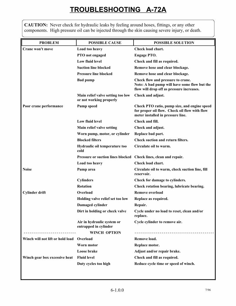
Reduce cycle time or speed of winch.Duty cycles too highCheck and fill as required.Fluid levelWinch gear box excessive heatAdjust and/or repair brake.Loose brakeReplace motor.Worn motorRemove load.OverloadWinch will not lift or hold load
WINCH OPTION- - - - - - - - - - - - - - - - - - - - - - - - - - - - - - - - - - - - - - - - - - - - - - - - - - - - - - - - - - - - - - - - - - - -
Cycle cylinder to remove air.Air in hydraulic system orentrapped in cylinder
Cycle under no load to reset, clean and/orreplace.
Dirt in holding or check valveRepair.Damaged cylinderReplace as required.Holding valve relief set too lowRemove overloadOverloadCylinder driftCheck rotation bearing, lubricate bearing.RotationCheck for damage to cylinders.Cylinders
Circulate oil to warm, check suction line, fillreservoir.
Pump areaNoiseCheck load chart.Load too heavyCheck lines, clean and repair.Pressure or suction lines blocked
Circulate oil to warm.Hydraulic oil temperature toocold
Check suction and return filters.Blocked filtersReplace bad part.Worn pump, motor, or cylinderCheck and adjust.Main relief valve settingCheck and fill.Low fluid level
Check PTO ratio, pump size, and engine speedfor proper oil flow. Check oil flow with flowmeter installed in pressure line.
Pump speedPoor crane performance
Check and adjust.Main relief valve setting too lowor not working properly
Check flow and pressure to crane. Note: A bad pump will have some flow but theflow will drop off as pressure increases.
Bad pumpRemove hose and clear blockage.Pressure line blocked Remove hose and clear blockage.Suction line blockedCheck and fill as required.Low fluid levelEngage PTO.PTO not engagedCheck load chart.Load too heavyCrane won't move
POSSIBLE SOLUTIONPOSSIBLE CAUSEPROBLEM
TROUBLESHOOTING A-72A
CAUTION: Never check for hydraulic leaks by feeling around hoses, fittings, or any othercomponents. High pressure oil can be injected through the skin causing severe injury, or death.
6-1.0.0 7/96

TROUBLESHOOTING A-72AOPTIONAL REMOTE CONTROL SYSTEM
remove and clean cartridge, clean hydraulicsystem
hydraulic contamination insolenoid cartridge
check wiring, replace wiring harness ifrequired
wiring-wires shorted togetherat terminal strip, pendant head,or receptacles
two functions operate at the same time
check wiring connection, replace if requiredwiring connections at terminalstrip, pendant, and receptacles
check voltage output for smooth, consistantchange as trigger is pulled
trigger potentiometer voltageerratic
check wiring at power build-up solenoidpower build-up solenoidwiring loose
crane operation is erratic
check relay wiringpower relay not operatingcorrectly
check trigger voltage outputtrigger potentiometer voltageoutput not changing
check amplifier setup and outputamplifier not adjusted properlycheck wiring, replace 8 amp fusefuse blown
check voltage at terminal #14no power crane will not operate with remote pendant
adjust trigger voltage to .4-.6 volts whentrigger is released, and/or replace
trigger potentiometer voltage too high
unscrew manual overrideproportional valve's manualoverride screwed in
crane operates full speed "no trigger control"
POSSIBLE SOLUTIONPOSSIBLE CAUSEPROBLEM
CAUTION: Never check for hydraulic leaks by feeling around hoses, fittings, or any othercomponents. High pressure oil can be injected through the skin causing severe injury, or death.
6-2.0.0 10/96
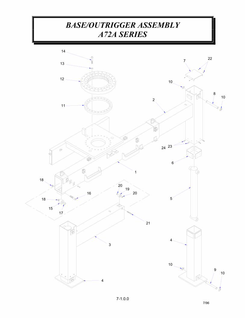
BASE/OUTRIGGER ASSEMBLYA72A SERIES
7-1.0.07/96
4
3
17
18
15
1619
20
10
4
910
21
5
1820
1
11
12
13
14
6
24 23
2
810
10
7 22

BASE/OUTRIGGER ASSEMBLYA72A SERIES
7-1.1.07/96
WASHER, SPLIT LOCK 1/424 16 020200
OUTRIGGER WELDMENTBASE, WELDMENT
LEG, INNER WELDMENTHYDRAULIC CYLINDER, (OUTRIGGER DOWN)
OUTRIGGER WELDMENT
COVER, OUTRIGGERSPACER, OUTER LEG
PIN, OUTRIGGER (LOWER)PIN, OUTRIGGER (UPPER)
ROTATION BEARINGSPACER, INNER RACERING, RETAINING 1"
SCREW, SOC. HD. 5/8-NC X 4" LG.WASHER, FLAT 5/8 HARDENED
BOLT WITH GREASE ZERK, 3/4-NC X 4ROLER BEARING, 2 1/2" O.D.
NUT, HEX-JAM 3/4-NCTUBING, 1 5/16 O.D. X 1/4 WALL X 3/4 LONG
SCREW, SET 1/2-NC X 3 LONGNUT, HEX-JAM 1/2-NCROLLER BEARING, 1 3/4 O.D.
SCREW, HEX HD. 1/4-NC X 1/2 LONGSCREW, THREAD- CUT #10-24
219
2322
168
2021
42
21718 4
1615
22
240234
370470005901
372219372218
800456-003373076
366197373077
810
112
1413
2424
11 1
98
22
76
28
360122
373031023902373078
373079
373209373210
373104369331
1345
22
21
11
ITEM QTY.
373067373074373042
373060373068
PART NO. DESCRIPTION
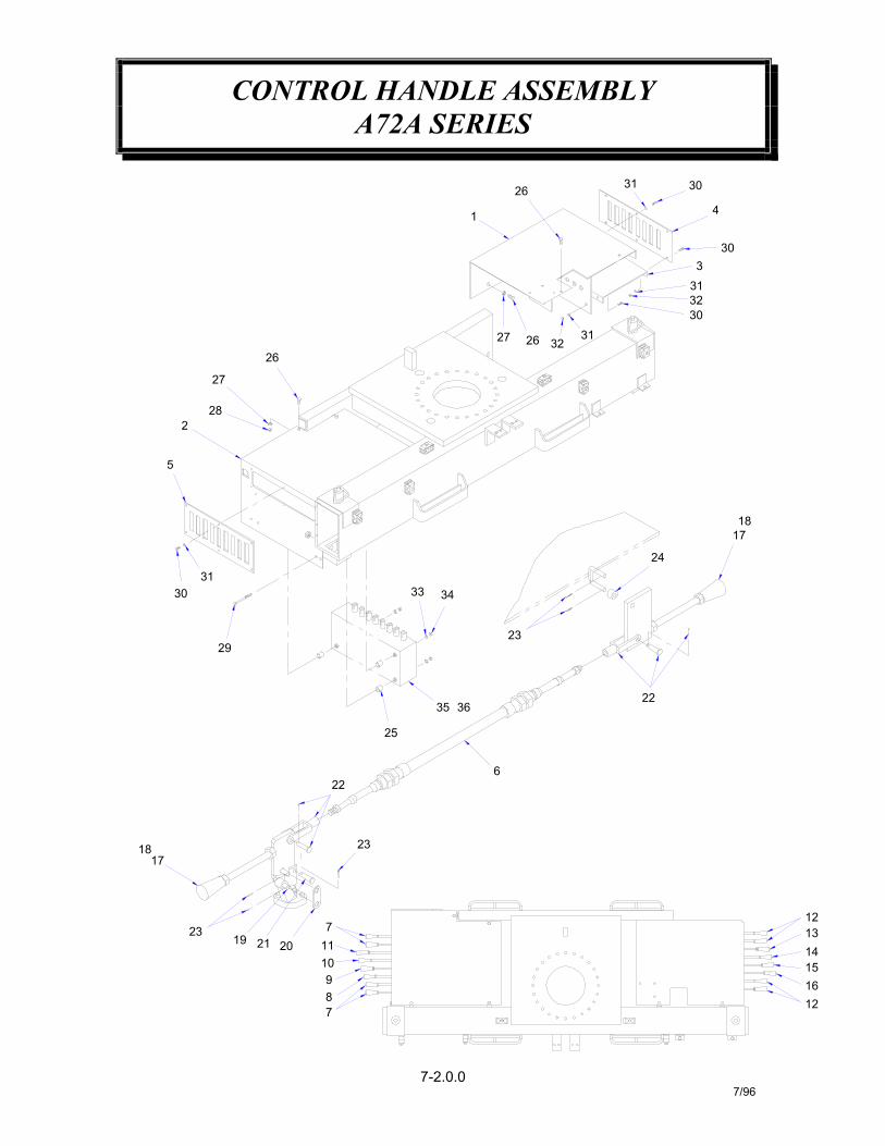
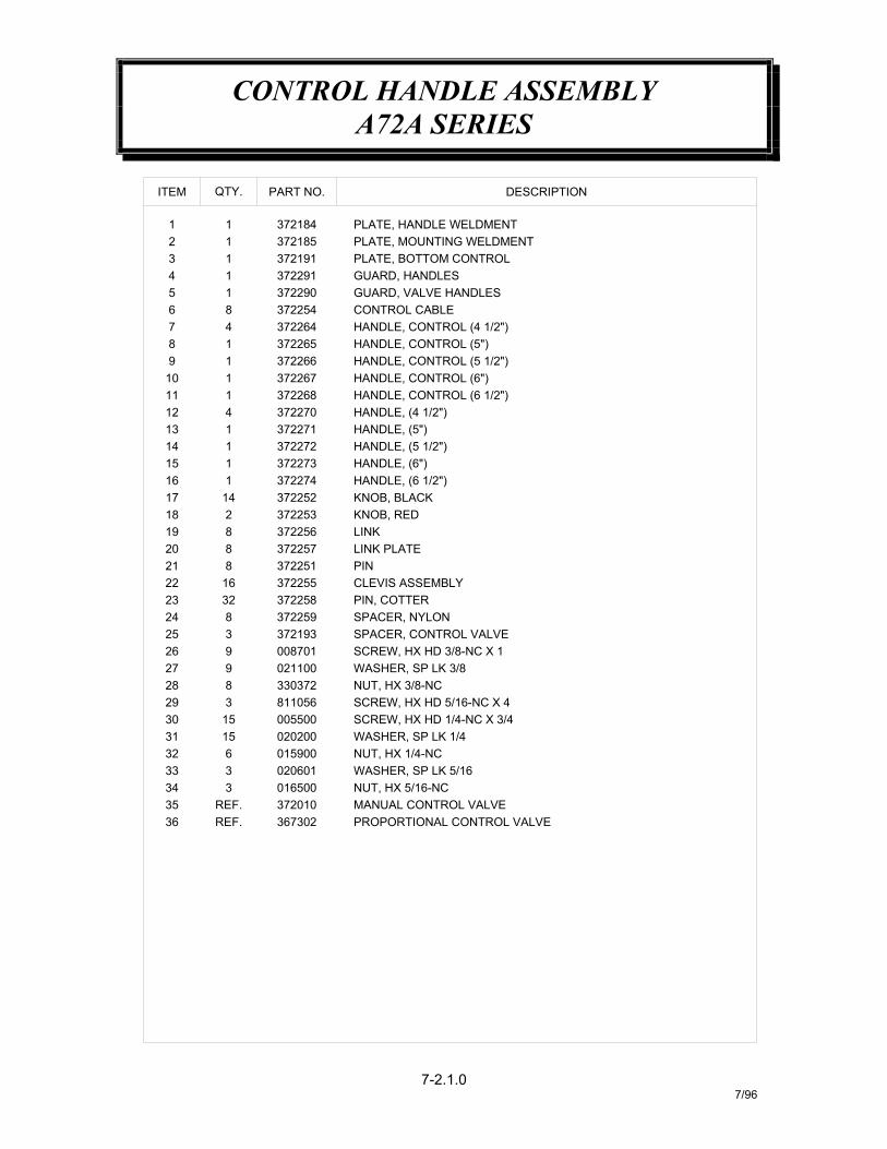
CONTROL HANDLE ASSEMBLYA72A SERIES
7-2.0.07/96
3031
303
3230
31
426
313227 26
1
1817
24
23
3433
27
282
5
31
29
30
26
22
12
1413
6
3635
25
1612
15
22
1110
721 20
17
1923
18
987
23
CONTROL HANDLE ASSEMBLYA72A SERIES
7-2.1.07/96
SCREW, HX HD 3/8-NC X 100870126 9
01650034 3
REF.REF.
3635
367302372010
3
15
36
15
98
3031
3332
29
2728
005500020200015900020601
021100
811056330372
NUT, HX 5/16-NCMANUAL CONTROL VALVEPROPORTIONAL CONTROL VALVE
SCREW, HX HD 1/4-NC X 3/4SCREW, HX HD 5/16-NC X 4
NUT, HX 1/4-NCWASHER, SP LK 1/4
WASHER, SP LK 5/16
NUT, HX 3/8-NCWASHER, SP LK 3/8
3722669 1
37225217 14
3
8
832
816
28
25242322
2021
1819
372193
372255372258372259
372253
372257372251
372256
11114
11
13
161514
12
1011
372271372272372273372274
372268372270
372267
41
811111
4
8765
23
1
372291
372264372265
372254372290
372184372185372191
QTY.ITEM PART NO.
HANDLE, CONTROL (5 1/2")
KNOB, BLACK
SPACER, CONTROL VALVE
PIN, COTTERCLEVIS ASSEMBLY
SPACER, NYLON
KNOB, RED
LINK PLATELINK
PIN
HANDLE, CONTROL (6 1/2")HANDLE, CONTROL (6")
HANDLE, (5")
HANDLE, (6 1/2")
HANDLE, (5 1/2")HANDLE, (6")
HANDLE, (4 1/2")
PLATE, MOUNTING WELDMENTPLATE, HANDLE WELDMENT
GUARD, VALVE HANDLES
PLATE, BOTTOM CONTROL
HANDLE, CONTROL (4 1/2")HANDLE, CONTROL (5")
GUARD, HANDLES
CONTROL CABLE
DESCRIPTION
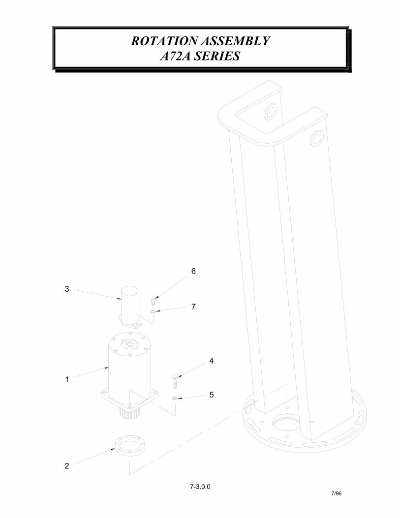
ROTATION ASSEMBLYA72A SERIES
7-3.0.07/96
2
1
5
4
3
6
7

ROTATION ASSEMBLYA72A SERIES
7-3.1.07/96
ITEM NO. QTY. PART NO. DESCRIPTION1 1 373044 SWING DRIVE2 1 373045 ECCENTRIC RING3 1 368120 HYDRAULIC MOTOTR4 4 012198 SCREW HX HD 5/8 NC X 1 3/45 4 023800 WASHER SP LK 5/86 2 368119 SCREW SOC HD 1/2 NC X 1 1/4 LG GR87 2 021500 WASHER SP LK 1/2
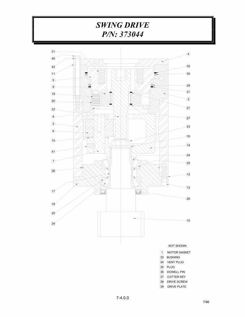
SWING DRIVEP/N: 373044
7-4.0.07/96
24
25
18
17
DOWELL PIN
DRIVE SCREW
DRIVE PLATE
COTTER KEY
MOTOR GASKET
BUSHING
VENT PLUG
PLUG35
39
38
36
37
33
34
1
NOT SHOWN
15
12
26
13
19
7
28
41
10
6
20
2
8
22
9
5
42
11
40
21
23
14
24
16
25
3
27
27
31
29
4
32
30

SWING DRIVEP/N: 373044
7-4.1.07/96
CAPSCREW, HX 3/8-NC X 4 1/2 G5SETSCREW, SOC. 5/16-NC X 1/2
PIN, DOWELL 1/2 X 1 1/4KEY, COTTER 1/8 X 1 1/2
BUSHING, RED 1/2-1/8 NPT
368024-027368024-026
368024-032368024-031368024-030368024-029368024-028
368024-037368024-036
368024-034368024-035
368024-033
368024-041368024-040368024-039368024-038
368024-042
134
42414039
6361
3837
3536
21
12
130
3233
3111
1
29282726
1121
PLUG, VENTPLUG, STR, THD
DRIVE SCREWLABEL PLATE
LOCKWASHER, 3/8
SEALSNAP RING
O-RINGO-RINGRING, BACK-UPRING, BACK-UP
O-RING
SHAFT, PLANET GEAR
CAPSCREW, FERRY 7/16-NC X 1 1/4
GASKET, HYD. MOTOR (1/32)
368024-009
368024-014368024-013
368024-011368024-012
368024-010
368024-018368024-017368024-016373044-015
368024-023368024-022368024-021368024-020368024-019
368024-025368024-024
117
25242322
2211
192021
187714
1
513
1516
1411
1
1211109
1231
SPACER, BEARINGBASE
PLATE, BACK-UPNUT, CASTELL
DISC, BRAKESPRING, BRAKE
DISC, FRICTION
BEARING, CONEBEARING, CUP
DRIVER, BRAKE
GASKETGASKET
CARRIER, PLANET
BEARING, THRUST
SHAFT, OUTPUTWASHER, SPACER
PART NO.
368024-003368024-004
368024-002368024-001
368024-008368024-007368024-006368024-005
14
8765
1331
23
111
1
ITEM QTY.
HOUSINGCYLINDER, BRAKECOVER, A2 PILOT
GEAR, INPUT
GEAR, PLANETPISTON, BRAKE
DESCRIPTION
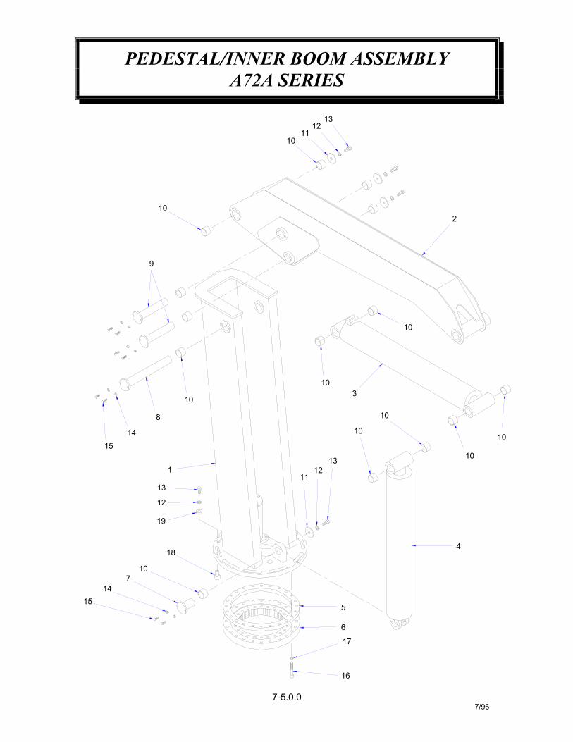
PEDESTAL/INNER BOOM ASSEMBLYA72A SERIES
7-5.0.07/96
14
16
6
515
17
107
18
12
19
13
1
15
10
14
8
13
1112
10
10
9
1011
1312
4
10
10
3
10
10
10
2

PEDESTAL/INNER BOOM ASSEMBLYA72A SERIES
7-5.1.07/96
11
1819
17161514
1213
10987
456
32
ITEM
1
DESCRIPTION
HYDRAULIC CYLINDER, LIFTRING SPACER (OUTER RACE)
HYDRAULIC CYLINDER, OUTER BOOM
SCREW, HX HD 5/8-NC X 1 1/2 G5
SCREW, SOC HD 5/8-NC X 4SCREW, HX HD 3/8-NC X 1 1/4
WASHER, FLAT 5/8 HARDENED
4 367049 WASHER, PIN
WASHER, SP LK 3/8
WASHER, SLIDE STOPPIN, SLIED STOP
WASHER, SP LK 5/8
373087
023902373086
008702373078
023800013508021100
11
242488
55
BUSHING
PIN, LIFT CYLINDERROTATION BEARING
PINPIN
INNER BOOM MACHINEPEDESTAL, MACHINE
373080
367149
373201373203
373031367071
373034373032
373090
15211
111
11
373081
PART NO.QTY.
1
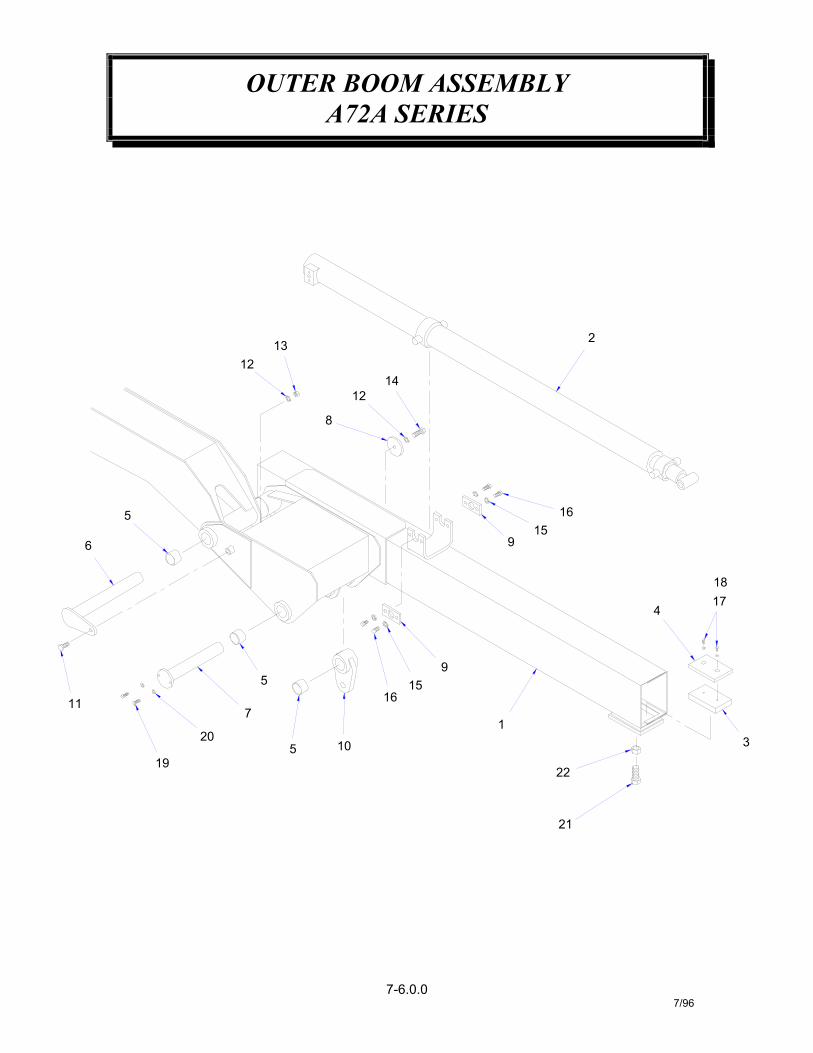
OUTER BOOM ASSEMBLYA72A SERIES
7-6.0.07/96
11
5
19
20
7
5 10
1516
9
21
1
22
3
6
5
12
12
8
13
14
915
16
174
18
2
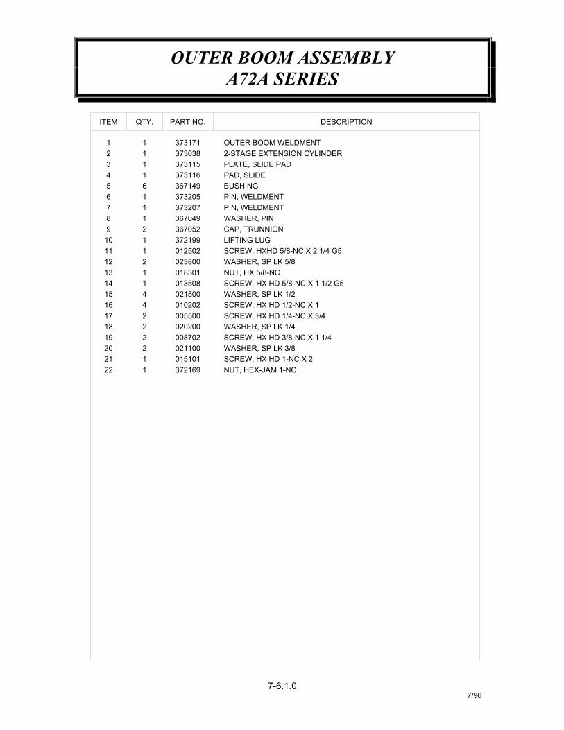
OUTER BOOM ASSEMBLYA72A SERIES
7-6.1.07/96
DESCRIPTION
2-STAGE EXTENSION CYLINDEROUTER BOOM WELDMENT
SCREW, HXHD 5/8-NC X 2 1/4 G5
SCREW, HX HD 5/8-NC X 1 1/2 G5
SCREW, HX HD 1/2-NC X 1SCREW, HX HD 1/4-NC X 3/4
SCREW, HX HD 1-NC X 2
SCREW, HX HD 3/8-NC X 1 1/4
36714965 BUSHING
008702219
22 1
2021
21
372169
021100015101
1817
22
1615
44
005500020200
021500010202
WASHER, SP LK 3/8
NUT, HEX-JAM 1-NC
WASHER, SP LK 1/2
WASHER, SP LK 1/4
372199110
212
1413
11
11 1023800018301013508
012502
98
21
76
11
367049367052
373205373207
LIFTING LUG
WASHER, SP LK 5/8NUT, HX 5/8-NC
PIN, WELDMENTPIN, WELDMENT
CAP, TRUNNIONWASHER, PIN
134 1
21
11
373115373116
373171373038
QTY.ITEM PART NO.
PAD, SLIDEPLATE, SLIDE PAD
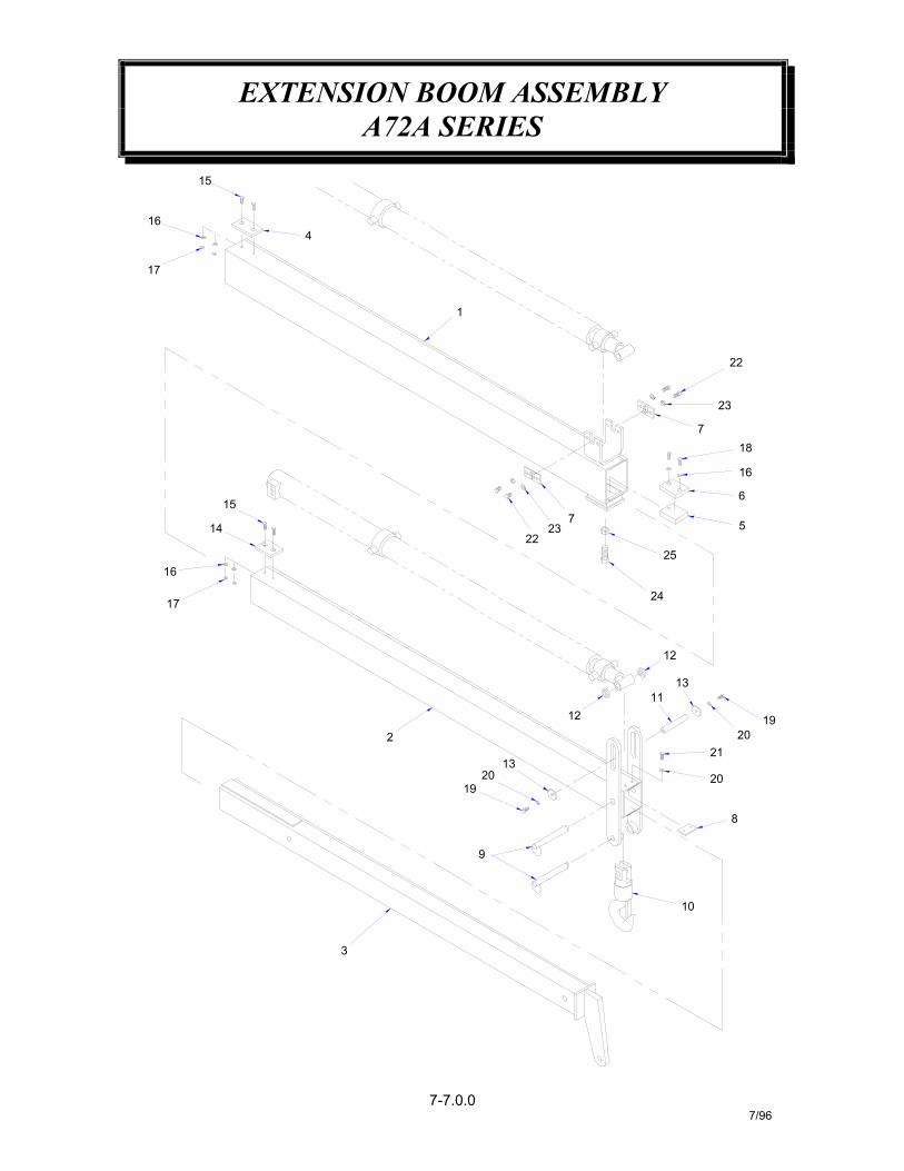
EXTENSION BOOM ASSEMBLYA72A SERIES
7-7.0.07/96
5
6
18
16
7
23
22
10
8
13
13
1211
12
19
20
2120
17
16
3
9
2
2019
15
14
15
17
164
1
25
24
2322
7

EXTENSION BOOM ASSEMBLYA72A SERIES
7-7.1.07/96
DESCRIPTIONITEM QTY. PART NO.
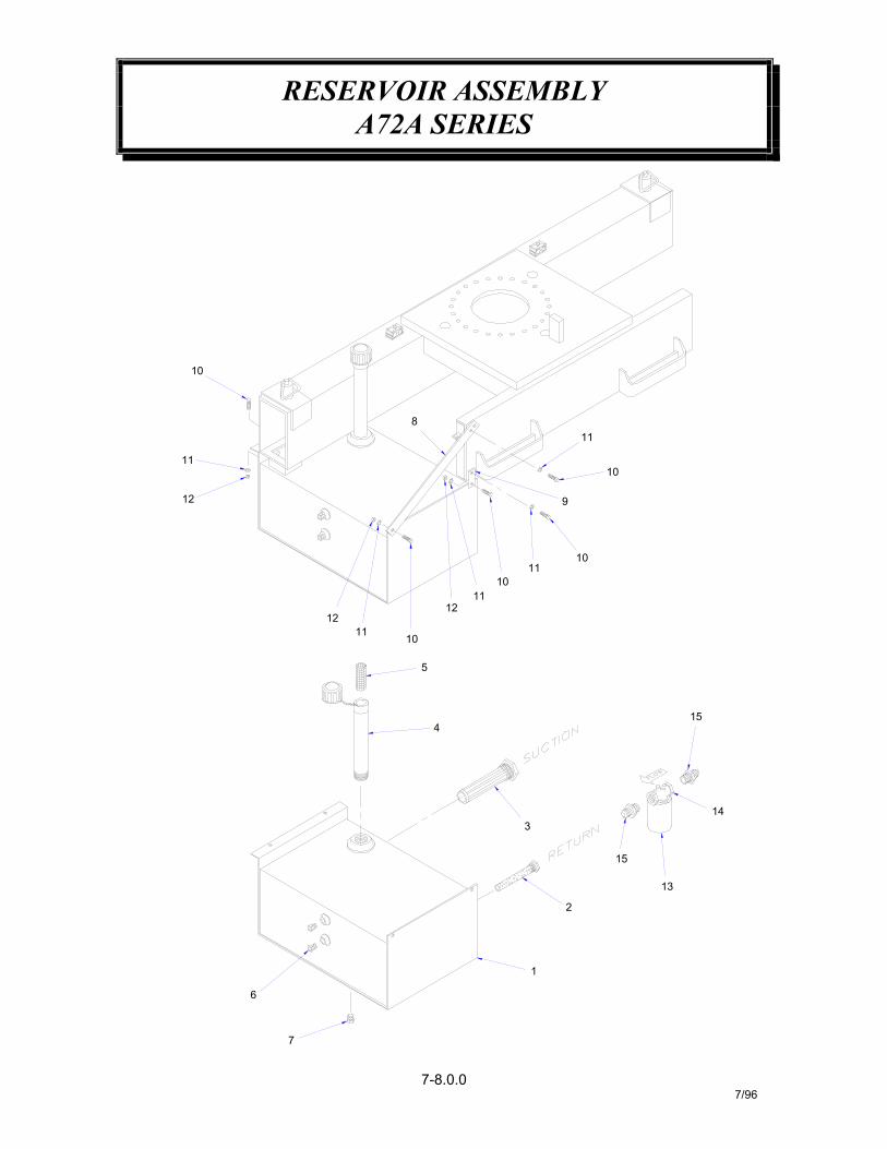
RESERVOIR ASSEMBLYA72A SERIES
7-8.0.07/96
4
5
1
13
2
3
15
14
15
10
12
12
1011
1211
11
10
8
6
9
1011
10
11
7

RESERVOIR ASSEMBLYA72A SERIES
7-8.1.07/96
PART NO.QTY.ITEM DESCRIPTION
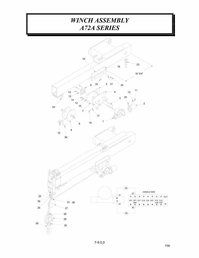
WINCH ASSEMBLYA72A SERIES
7-9.0.07/96
6 22 215
19
32 3/4"
353
4 12
19 16
7
15
17
12
1214
13
36
39
26
2930
28
36
27
37, 38
25
2
11
20
1823
A
32
34
31 B B B B B B B INB
HANDLE SIDE32
B31
A
33
A A A A A A A
108
24

WINCH ASSEMBLYA72A SERIES
7-9.1.07/96
SIDEPLATE WELDMENT (WINCH SIDE)4 1 372228
35
37
3938
36
34333231
26
28
3029
27
2425
2322
367306-001
367407-001367313-003
812306-285812309-285
1
11
11
1122
360124360607
372041372195
1
1
11
1
1114
367306
368178480366330009
368177
230400368175
018301368142
17
2021
1918
1516
1413
8
1211109
67
5
4
244
1
4244
750223
372236012198023800
372235
480070367406
010201017701
1
1
102
2
1
21
367399
367313
021500368119
367404
372230367402480069
SNATCH BLOCK ASSEMBLY
SWIVEL, -10 O-RING / -8 JICADAPTER, STR. -10 O-RING / -8 JIC
KEY, WOODRUFFHOSE ASSEMBLYHOSE ASSEMBLY
HITCH PINPIN
PIN
PIN
OVERHAUL ASSEMBLY
POSITION PINHOOK SWIVEL
ADAPTER, BLOCKHOIST CABLE HOOK
SWIVEL, SHEAVE BLOCK
HOSE CLAMPNUT, 5/8-NC
SIDEPLATE WELDMENT (BEARING SIDE)
SCREW, SOC. HD 1/2-NC X 1 1/4 LG.
SCREW, 1/2-NC X 1 1/2 G5
SCREW, HX HD 7/16-NC X 1
BOX, ACTUATOR WELDMENT
SCREW, HX HD 5/8-NC X 1 3/4 G8
BEARING, 4-BOLT FLANGE
NUT, HX 1/2-NC
HANGER, ACTUATOR
WASHER, SP-LK 5/8
SPACER ROD
WASHER, SP-LK 7/16
CABLE ASSEMBLY
WASHER, SP-LK 1/2
SPACER TUBEDRUMSPACER
ITEM
321
QTY.
111
PART NO.
372234
367403367407
DESCRIPTION
HYDRAULIC MOTORKEY, SQUARE 1/2 X 4
ACTUATOR

WINCH ASSEMBLYA72A SERIES
7-10.0.07/96

WINCH ASSEMBLYA72A SERIES
7-10.1.07/96
5 1 367453
19 1 3674742021
12 367488
367487
1817
11
1615
11
367466367465367464367463
10 6 367458
12 1
1413
21
11 2367460
367462367461
367459
98
82
76
21
367457367456367455367454
3 24 1
21
11
367451367452
367450367449
ITEM QTY. PART NO.
GEAR R.H. 334016
WORM, R.H.SHAFT, OUTPUTKEY
PLUG, PIPEOIL SEAL
REDUCERPLUG, PIPE
368057357160342120
468011486067
468002468010
CAPSCREW, 5/16-NC X 1 1/4
FITTING, RELIEFGASKET
QUAD RING
GASKET
CAPSCREW, 5/16-NC X 3/4
HOUSING, GEAR
BALL BEARINGKEY, RD. END
414138
442183456008462003
442182
402044414140
338010342051
DESCRIPTION
COUPLING ASSEMBLY
BUSHINGCOVER
ADAPTER308048328010
324212300043
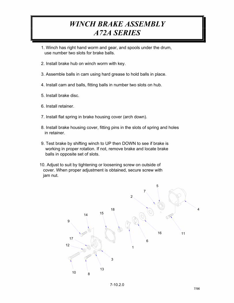
WINCH BRAKE ASSEMBLYA72A SERIES
7-10.2.07/96
jam nut.
81013
12
17
9
3
1
14
2
1815
6
16 11
57
4
1. Winch has right hand worm and gear, and spools under the drum,
2. Install brake hub on winch worm with key.
3. Assemble balls in cam using hard grease to hold balls in place.
4. Install cam and balls, fitting balls in number two slots on hub.
7. Install flat spring in brake housing cover (arch down).
8. Install brake housing cover, fitting pins in the slots of spring and holes
9. Test brake by shifting winch to UP then DOWN to see if brake is working in proper rotation. If not, remove brake and locate brake
10. Adjust to suit by tightening or loosening screw on outside of cover. When proper adjustment is obtained, secure screw with
balls in opposite set of slots.
in retainer.
5. Install brake disc.
6. Install retainer.
use number two slots for brake balls.

WINCH BRAKE ASSEMBLYA72A SERIES
7-10.3.07/96
CAPSCREW, 3/8-24NF X 1 G5CAPSCREW, 5/16-18NC X 1 G5
NUT, JAM 1/2-20NF HXCAPSCREW, 5/16-18NF X 1 SOC. HDCAPSCREW, 1/2-20NF X 1 3/4 G5
WASHER, FLAT 3/8 ALUM.
HUB36747115
36748336748436748536748618
171615
1111 GASKET
SPRING
THRUST PLATETHREAD SEAL
367473367475367476367477
367480367479
367481367482
367478110
12
1413
111
24
6
9876
2421
LOCKWASHER, 5/16
RETAINER PLATEBALL
PART NO.
367467367468
3674703674693
4
21
11
11
ITEM QTY.
COVERCAM PLATESPRING, FLAT
HOUSING, BRAKE340024
494010486076474004442190
414603
418067
418184418163
414865
414398414111400007352020
DESCRIPTION
328057338038
314003306036
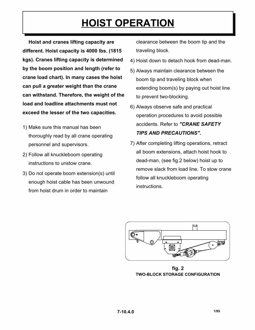
Hoist and cranes lifting capacity are
different. Hoist capacity is 4000 lbs. (1815
kgs). Cranes lifting capacity is determined
by the boom position and length (refer to
crane load chart). In many cases the hoist
can pull a greater weight than the crane
can withstand. Therefore, the weight of the
load and loadline attachments must not
exceed the lesser of the two capacities.
1) Make sure this manual has been
thoroughly read by all crane operating
personnel and supervisors.
2) Follow all knuckleboom operating
instructions to unstow crane.
3) Do not operate boom extension(s) until
enough hoist cable has been unwound
from hoist drum in order to maintain
clearance between the boom tip and the
traveling block.
4) Hoist down to detach hook from dead-man.
5) Always maintain clearance between the
boom tip and traveling block when
extending boom(s) by paying out hoist line
to prevent two-blocking.
6) Always observe safe and practical
operation procedures to avoid possible
accidents. Refer to "CRANE SAFETY
TIPS AND PRECAUTIONS".
7) After completing lifting operations, retract
all boom extensions, attach hoist hook to
dead-man, (see fig.2 below) hoist up to
remove slack from load line. To stow crane
follow all knuckleboom operating
instructions.
HOIST OPERATION
fig. 2TWO-BLOCK STORAGE CONFIGURATION
1/957-10.4.0

1 Hoist capacity 4000 lbs (1815 kgs).
2 Payout hoist loadline before or duringboom extension to avoid two-blocking.
3 Do not lift personnel with any wire ropeattachment or hook.
4 Never unreel last 5 wraps of hoist cablefrom drum.
5 Check the hoist brake for properoperation before handling the load.
6 Do not drag loads with hoist or boom.
7 Always wind loadline under tension toassist proper spooling.
8 Never attempt to lift loads which are notlooose and free, i.e. frozen downmaterial or poles out of ground.
9 Know hoist and cranes lifting capacitiesbefore attempting to lift load. Theweight of the load and loadlineattachments must not exceed the lesserof the two capacities.
10 Never use the two-block storage hook(s) to lift a load.
SAFETY TIPS AND PRECAUTIONSOPTIONAL HOIST
1/957-10.5.0
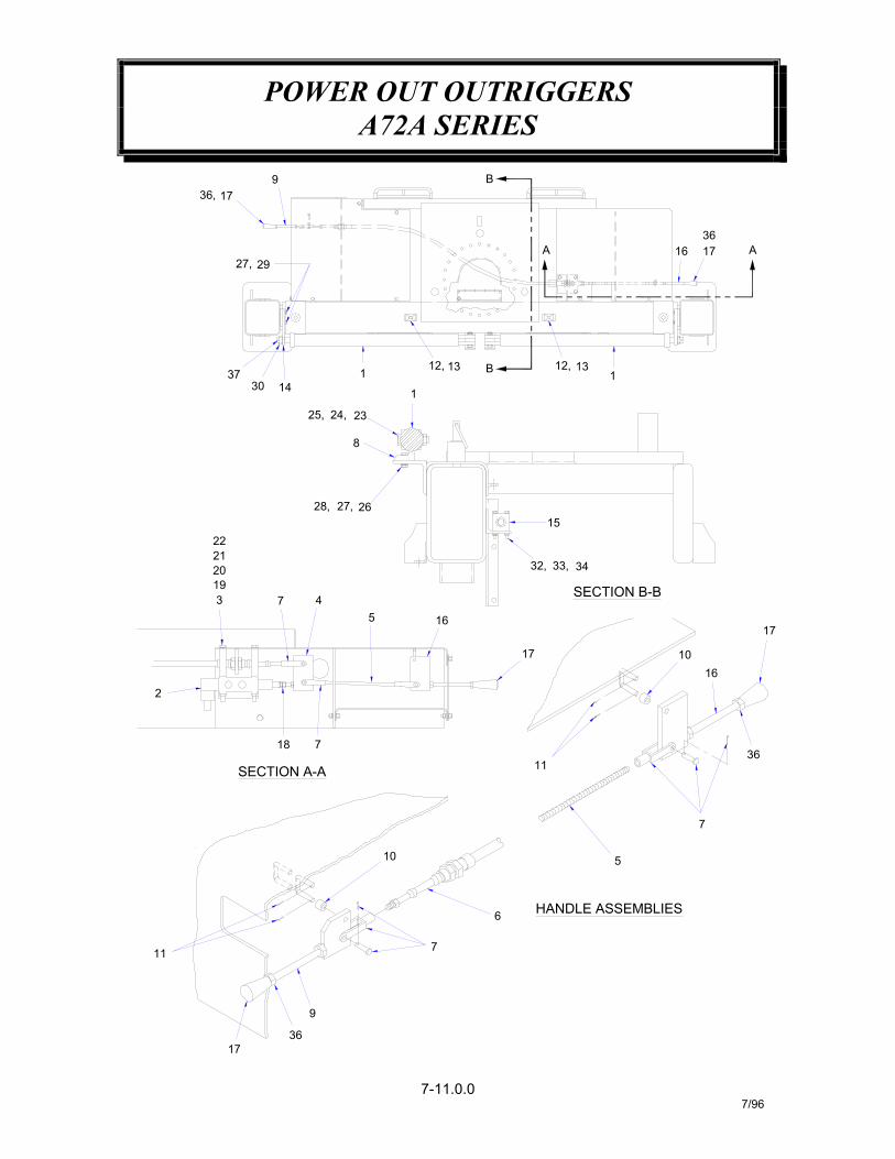
POWER OUT OUTRIGGERSA72A SERIES
7-11.0.07/96
3
2019
22
7 4
28, 27,
37
8
24,25,
30 14
9
27,
36, 17
29
13
34
SECTION B-B
5 16
33,32,
15
36
9
11
17
5
7
10
36
16
23
26
21
17
17
11
SECTION A-A
2
18 7
7
HANDLE ASSEMBLIES
10
6
1
1
12, 13 B 12,1
B
A 16 17 A36

POWER OUT OUTRIGGERSA72A SERIES
7-11.1.07/96
224 023800 WASHER SP LK 5/8
WASHER, SP LK 3/8SCREW, HX HD 3/8-NC X 1 1/2
SCREW, HX HD 3/8-NC X 1
SCREW, HX HD 1/4-NC X 2 1/2
DECAL, 5-WAY VALVE FUNCTION
WASHER, SP LK 1/4233
3736
3435
22
22
3132
2930
-2
42
2728
2526
84
24
020200
PIN, HITCH
NUT, HX 1/4-NC
NUT, HX 3/8-NC372321015900
330372360124
NUT, HX 5/8-NC
NUT, HX 3/8-NC
NUT, HX-JAM 1-NC008701372169
006700- -
021100
018302330394
330372
5-WAY DIRECTIONAL VALVECYLINDER, POWER OUT OUTRIGGER
LINK PLATE WELDMENTROD, ALL THREAD 5/16-24 X 8 1/2 LG.
SPACER, 5-WAY VALVE
HANDLE, 5-WAY VALVEBRACKET, OUTRIGGER
BRACKET, OUTRIGGER ROD ENDSTACKING BOLT, 5/16-NC
WASHER, SP-LK 5/16WASHER, FLAT 5/16SCREW, HX HD 5/16-NC X 6
SCREW, HX HD 5/8-NF X 2 3/4
16 372312 PUSH-PULL CABLE
115
2223
2120
32
36
1819
1617
23
21
1314
1112
22
22
910
78
11
42
372305 HEADER MANIFOLD
NUT, HEX M8KNOB, BLACKHANDLE, (4 1/2")
NUT, HX 5/16-NC
020901020600016500013505
372270372252372308008000
PIN, COTTERSPACER, NYLON
CLEVIS ASSEMBLY
CLAMP ASSEMBLY368142372258
372043372317
372255372315372304372259
45
23
11
31
1
ITEM
2
QTY.
372311
372302372306
800513-001
PART NO. DESCRIPTION
373040
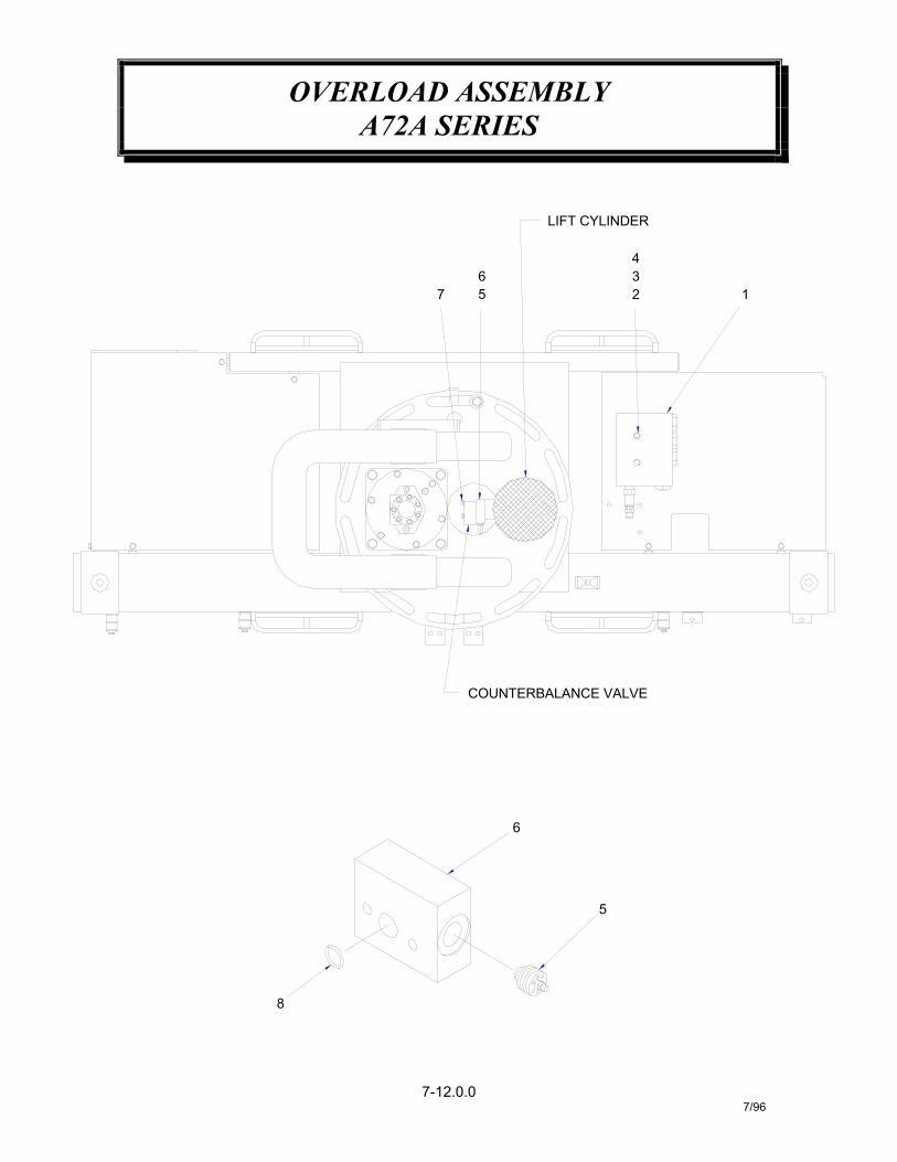
OVERLOAD ASSEMBLYA72A SERIES
7-12.0.07/96
8
6
5
COUNTERBALANCE VALVE
LIFT CYLINDER
7 56
234
1

OVERLOAD ASSEMBLYA72A SERIES
7-12.1.07/96
ITEM NO. QTY. PART NO. DESCRIPTION1 1 367285 3/2 FUNCTION OVERLOAD VALVE2 2 811052 SCREW HX HD 3/8 NC X 53 4 021200 WASHER FLAT 3/84 2 017301 NUT HX HD 3/8 NC5 1 368987 VELOCITY FUSE6 1 368985 MANIFOLD SENSE VALVE7 2 006700 SCREW HX HD 1/4 NC X 2 2/18 1 368985-001 O-RING SEAL
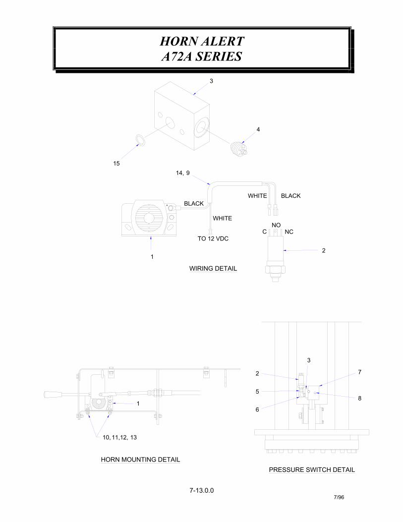
HORN ALERTA72A SERIES
7-13.0.07/96
PRESSURE SWITCH DETAIL
6
HORN MOUNTING DETAIL
1
5
2
8
7
3
WIRING DETAIL
BLACK+
1
TO 12 VDC
WHITE
1514, 9
3
12,10, 11, 13
2
NOC NC
BLACKWHITE
4

HORN ALERTA72A SERIES
7-13.1.07/96
368985-001
10 0054012
15 114131211
6'222
020300015900
020200750736
6 1
89
721
1
45
32
11
11
372054367122006700372380
369611
369610
368987368985
QTY.
1
ITEM
1 750733
PART NO.
ADAPTER, STR. -6 OR(M) / -4 OR(F)ELL, 90° -6 OR(M) / -6 OR(F)
SCREW, HX HD 1/4-NC X 2 1/2
SCREW, HX HD 1/4-NC X 5/8
COUNTERBALANCE VALVE
WIRE ASSEMBLY, HORN ALERT
VALVE, SENSE MANIFOLD
O-RING SEAL
WASHER FLAT 1/4NUT, HX 1/4-NC
WASHER, SP LK 1/4LOOM
PRESSURE SWITCH
VELOCITY FUSE
HORN ALERT
DESCRIPTION
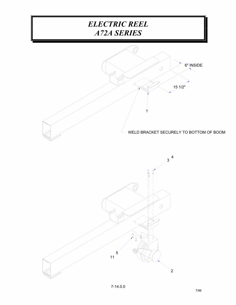
ELECTRIC REELA72A SERIES
7-14.0.07/96
1
43
6" INSIDE
15 1/2"
WELD BRACKET SECURELY TO BOTTOM OF BOOM
115
2
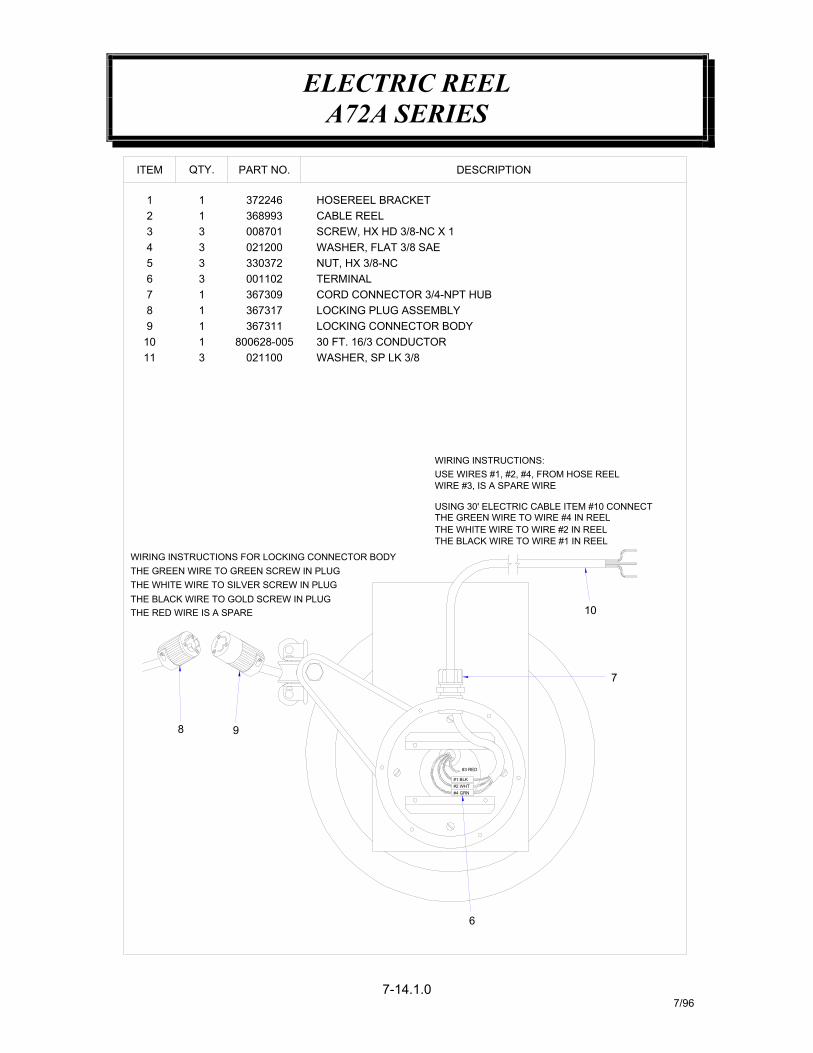
ELECTRIC REELA72A SERIES
7-14.1.07/96
#3 RED
ITEM
2
54
67
3
91011
8
1
3673171 LOCKING PLUG ASSEMBLYLOCKING CONNECTOR BODY
WASHER, SP LK 3/830 FT. 16/3 CONDUCTOR800628-005
311
021100
367311
CABLE REELHOSEREEL BRACKET
WASHER, FLAT 3/8 SAENUT, HX 3/8-NCTERMINAL
0087013
13
33
001102367309
021200330372
11
QTY.
372246368993
PART NO.
7
10
DESCRIPTION
USE WIRES #1, #2, #4, FROM HOSE REELWIRING INSTRUCTIONS:
SCREW, HX HD 3/8-NC X 1
CORD CONNECTOR 3/4-NPT HUB
THE GREEN WIRE TO WIRE #4 IN REELUSING 30' ELECTRIC CABLE ITEM #10 CONNECT
WIRE #3, IS A SPARE WIRE
THE BLACK WIRE TO WIRE #1 IN REELTHE WHITE WIRE TO WIRE #2 IN REEL
6
THE RED WIRE IS A SPARE
THE GREEN WIRE TO GREEN SCREW IN PLUGTHE WHITE WIRE TO SILVER SCREW IN PLUGTHE BLACK WIRE TO GOLD SCREW IN PLUG
WIRING INSTRUCTIONS FOR LOCKING CONNECTOR BODY
98
#4 GRN
#1 BLK#2 WHT

DUAL HOSE REELA72A SERIES
7-15.0.07/96
12
11
10
9
5 (WELD BRACKET TO EXTENSION BOOM)
67
3
2
WELD BRACKET SECURELY TO BOTTOM OF BOOM
1
15 1/2"
6" INSIDE
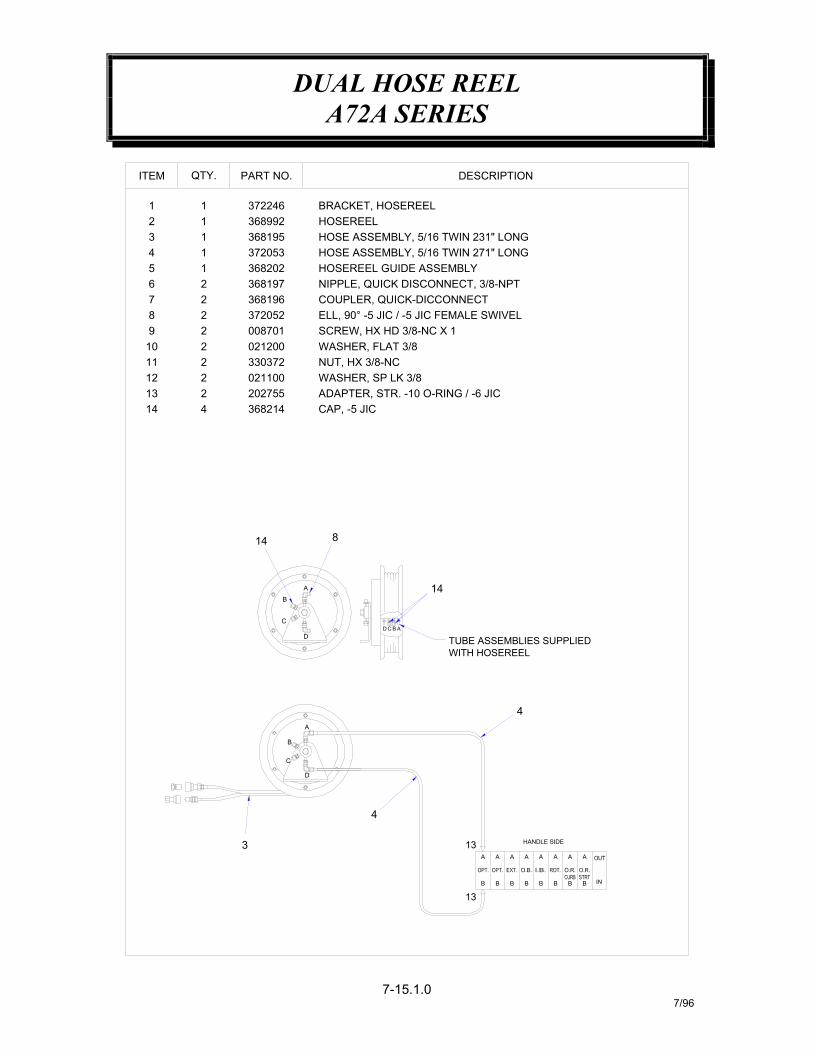
DUAL HOSE REELA72A SERIES
7-15.1.07/96
C
D
DESCRIPTION
HOSE ASSEMBLY, 5/16 TWIN 271" LONGHOSE ASSEMBLY, 5/16 TWIN 231" LONG
NIPPLE, QUICK DISCONNECT, 3/8-NPT
ELL, 90° -5 JIC / -5 JIC FEMALE SWIVEL
ADAPTER, STR. -10 O-RING / -6 JIC
WITH HOSEREELTUBE ASSEMBLIES SUPPLIED
3
13
4
B B
A A
13
B AD C
B
A
D
814
C
B
A 14
11
141312
8
109
76
45
3
12
ITEM
COUPLER, QUICK-DICCONNECT
SCREW, HX HD 3/8-NC X 1
WASHER, SP LK 3/8NUT, HX 3/8-NCWASHER, FLAT 3/8
CAP, -5 JIC
33037220211002027553682144
22
368197368196372052008701021200
2
22
22
HOSEREELBRACKET, HOSEREEL
HOSEREEL GUIDE ASSEMBLY
372246368992
372053368195
36820211
1
11
PART NO.QTY.
BB B
AA A
BB B
AA A
HANDLE SIDE
IN
4
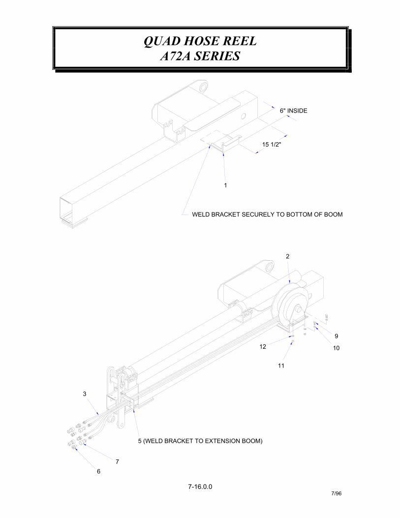
QUAD HOSE REELA72A SERIES
7-16.0.07/96
76
3
5 (WELD BRACKET TO EXTENSION BOOM)
11
12 10
9
WELD BRACKET SECURELY TO BOTTOM OF BOOM
1
2
15 1/2"
6" INSIDE
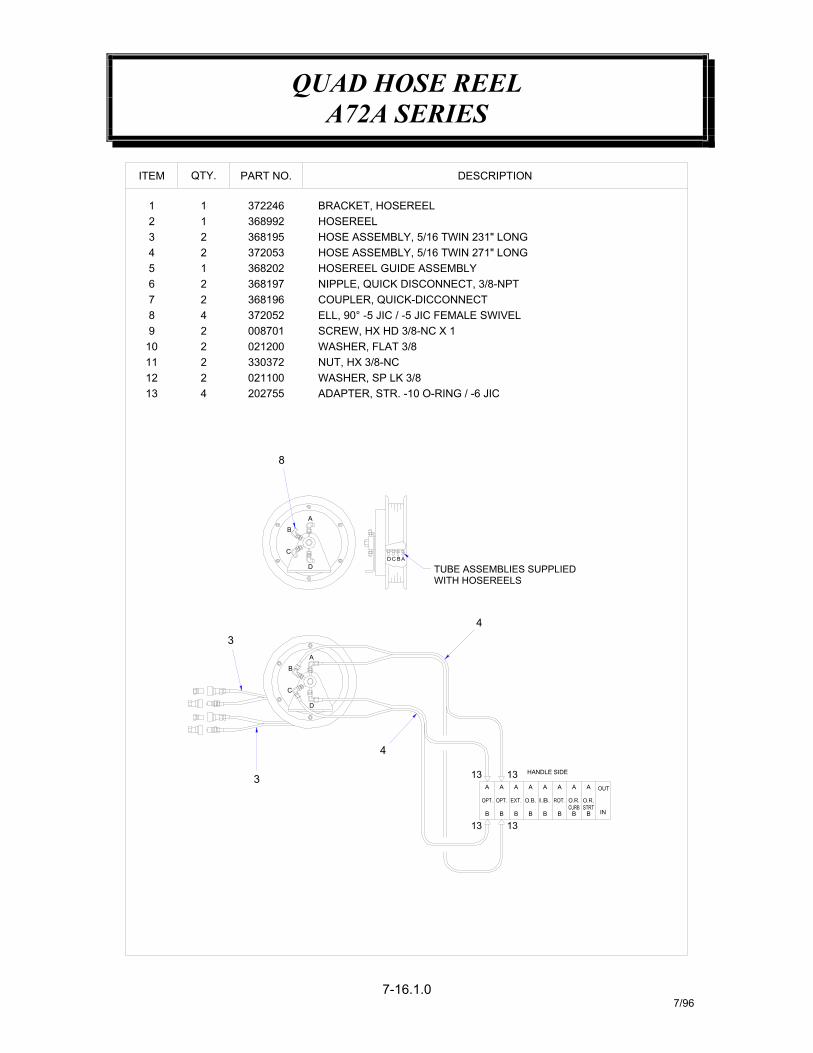
QUAD HOSE REELA72A SERIES
7-16.1.07/96
D
13
13B B
A A
4
DESCRIPTION
HOSE ASSEMBLY, 5/16 TWIN 271" LONGHOSE ASSEMBLY, 5/16 TWIN 231" LONG
NIPPLE, QUICK DISCONNECT, 3/8-NPT
ELL, 90° -5 JIC / -5 JIC FEMALE SWIVEL
ADAPTER, STR. -10 O-RING / -6 JIC
WITH HOSEREELSTUBE ASSEMBLIES SUPPLIED
13
13
BCD A
3
3
B
C
A
D
4
36820215 HOSEREEL GUIDE ASSEMBLY
10
1213
11
9876
C
B
A
8
COUPLER, QUICK-DICCONNECT
SCREW, HX HD 3/8-NC X 1
WASHER, SP LK 3/8NUT, HX 3/8-NCWASHER, FLAT 3/80212002
021100330372
20275524
2
3681973681963720520087012
422
34
21
ITEM
HOSEREELBRACKET, HOSEREEL372246
368992
3720533681952
2
11
PART NO.QTY.
HANDLE SIDE
BB B BB B
AA A AA A
IN
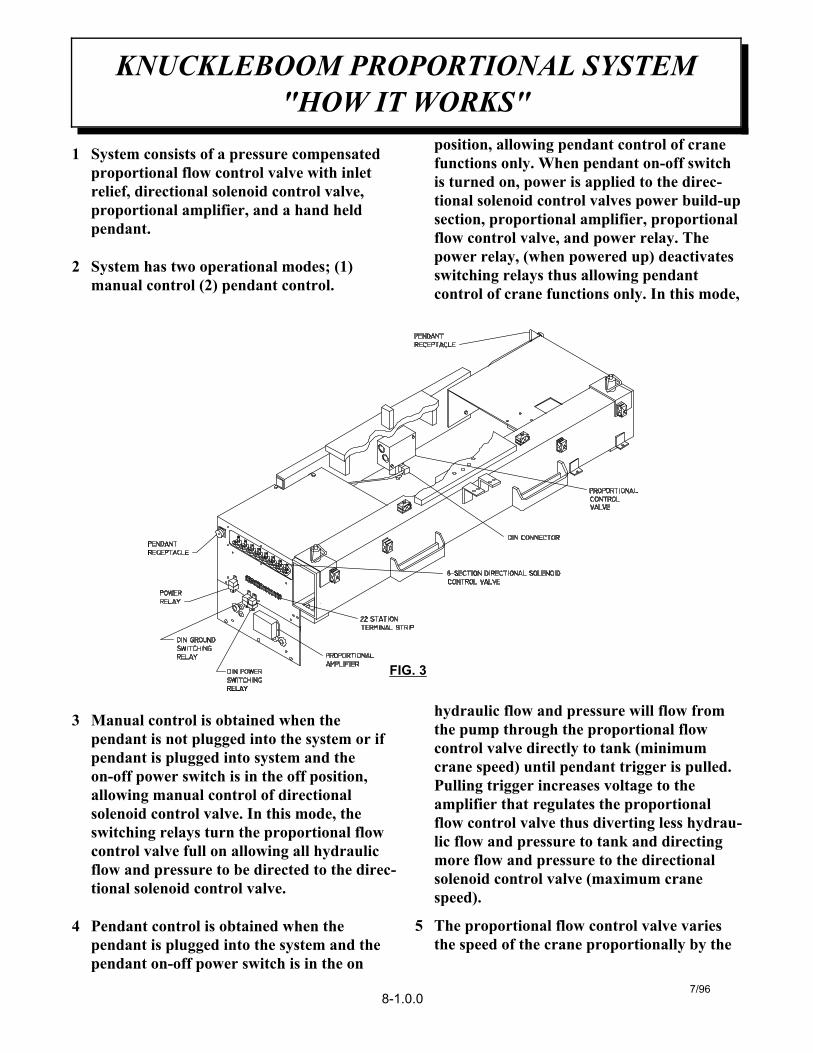
1 System consists of a pressure compensatedproportional flow control valve with inletrelief, directional solenoid control valve,proportional amplifier, and a hand heldpendant.
2 System has two operational modes; (1)manual control (2) pendant control.
3 Manual control is obtained when thependant is not plugged into the system or ifpendant is plugged into system and theon-off power switch is in the off position,allowing manual control of directionalsolenoid control valve. In this mode, theswitching relays turn the proportional flowcontrol valve full on allowing all hydraulicflow and pressure to be directed to the direc-tional solenoid control valve.
4 Pendant control is obtained when thependant is plugged into the system and thependant on-off power switch is in the on
position, allowing pendant control of cranefunctions only. When pendant on-off switchis turned on, power is applied to the direc-tional solenoid control valves power build-upsection, proportional amplifier, proportionalflow control valve, and power relay. Thepower relay, (when powered up) deactivatesswitching relays thus allowing pendantcontrol of crane functions only. In this mode,
hydraulic flow and pressure will flow fromthe pump through the proportional flowcontrol valve directly to tank (minimumcrane speed) until pendant trigger is pulled.Pulling trigger increases voltage to theamplifier that regulates the proportionalflow control valve thus diverting less hydrau-lic flow and pressure to tank and directingmore flow and pressure to the directionalsolenoid control valve (maximum cranespeed).
5 The proportional flow control valve variesthe speed of the crane proportionally by the
KNUCKLEBOOM PROPORTIONAL SYSTEM"HOW IT WORKS"
7/968-1.0.0
FIG. 3
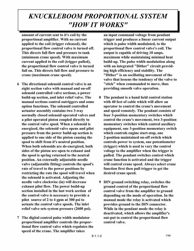
amount of current sent to it's coil by theproportional amplifier. With no currentapplied to the coil (trigger released), theproportional flow control valve is turned off.This directs full flow and pressure to tank(minimum crane speed). With maximumcurrent applied to the coil (trigger pulled),the proportional flow control valve is turnedfull on. This directs full flow and pressure tocrane (maximum crane speed).
6 The directional solenoid control valve is aneight section valve with manual and on-offsolenoid controlled valve sections, a powerbuild-up section, and inlet relief valve. The manual sections control outriggers and someoption functions. The solenoid controlledactuator assembly contains two 3-waynormally closed solenoid operated valves anda pilot operated piston coupled directly tothe control valve spool. When a solenoid isenergized, the solenoid valve opens and pilotpressure from the power build-up section isapplied to one side of the piston causing thespool to shift from it's neutral position.When both solenoids are de-energized, bothsides of the piston are open to exhaust andthe spool is spring returned to the neutralposition. An externally adjustable needlevalve (adjustable fitting) controls the spool'srate of travel to the power positions byrestricting the rate the spool will travel whenthe solenoid is activated. Adjusting theneedle valve clockwise (in) will decreaseexhaust pilot flow. The power build-upsection installed in the last work section ofthe control valve is necessary to provide apilot source of 2 to 4 gpm at 300 psi toactuate the control valve spools. The inletrelief valve sets system pressure (2600 psi).
7 The digital control pulse width modulatorproportional amplifier controls the propor-tional flow control valve which regulates thespeed of the crane. The amplifier takes
an input command voltage from pendanttrigger and produces a linear current outputwhich is pulse width modulated, to theproportional flow control valve's coil. Theoutput is capable of driving 10 amps.maximum while maintaining minimal heatbuild-up. The pulse width modulation alongwith an integrated "Dither" circuit provid-ing high efficiency and stability. The"Dither" is an oscillating movement of thevalve that lessens the tendency of the valve to"stick" when commanded to move, thusproviding smooth valve operation.
8 The pendant is a hand held control stationwith 40 feet of cable which will allow anoperator to control the crane's movementand speed remotely. The pendant consists offour 3-position momentary switches whichcontrol the crane's movement, two 3-positionmomentary switches which control auxiliaryequipment, one 3-position momentary switchwhich controls engine start-stop, one2-position maintained on-off switch whichcontrols power to system, one potentiometer(trigger) which is used to vary the controlvoltage to the amplifier when the trigger ispulled. The pendant switches control whichcrane function is activated and the triggerwill control crane speed. Always select cranefunction first then pull trigger to get thedesired crane speed.
9 DIN ground switching relay, switches theground control of the proportional flowcontrol valve from the amplifier to grounddepending on the mode of operation. In themanual mode the relay is activated whichprovides ground to the DIN connector.While in the pendant mode the relay isdeactivated, which allows the amplifier'sout-put to control the proportional flowcontrol valve.
KNUCKLEBOOM PROPORTIONAL SYSTEM"HOW IT WORKS"
8-1.1.0 7/96
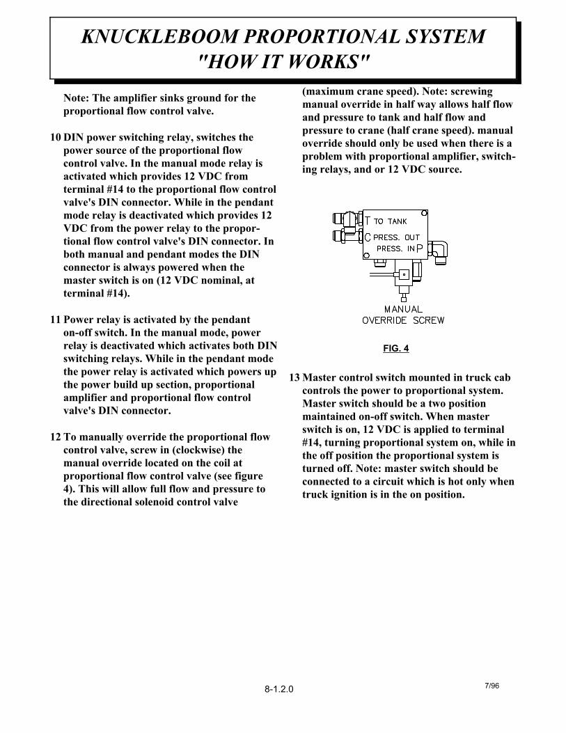
Note: The amplifier sinks ground for theproportional flow control valve.
10 DIN power switching relay, switches thepower source of the proportional flowcontrol valve. In the manual mode relay isactivated which provides 12 VDC fromterminal #14 to the proportional flow controlvalve's DIN connector. While in the pendantmode relay is deactivated which provides 12VDC from the power relay to the propor-tional flow control valve's DIN connector. Inboth manual and pendant modes the DINconnector is always powered when themaster switch is on (12 VDC nominal, atterminal #14).
11 Power relay is activated by the pendanton-off switch. In the manual mode, powerrelay is deactivated which activates both DINswitching relays. While in the pendant modethe power relay is activated which powers upthe power build up section, proportionalamplifier and proportional flow controlvalve's DIN connector.
12 To manually override the proportional flowcontrol valve, screw in (clockwise) themanual override located on the coil atproportional flow control valve (see figure4). This will allow full flow and pressure tothe directional solenoid control valve
(maximum crane speed). Note: screwingmanual override in half way allows half flowand pressure to tank and half flow andpressure to crane (half crane speed). manualoverride should only be used when there is aproblem with proportional amplifier, switch-ing relays, and or 12 VDC source.
13 Master control switch mounted in truck cabcontrols the power to proportional system.Master switch should be a two positionmaintained on-off switch. When masterswitch is on, 12 VDC is applied to terminal#14, turning proportional system on, while inthe off position the proportional system isturned off. Note: master switch should beconnected to a circuit which is hot only whentruck ignition is in the on position.
KNUCKLEBOOM PROPORTIONAL SYSTEM"HOW IT WORKS"
8-1.2.0 7/96
FIG. 4
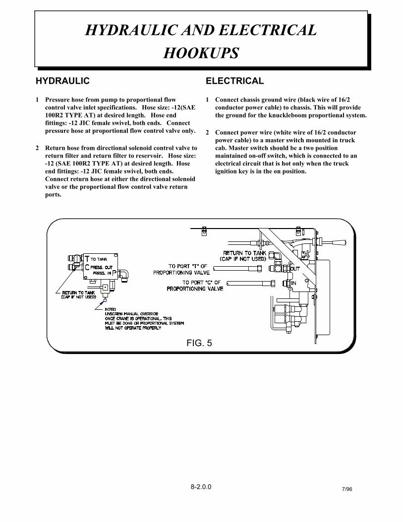
HYDRAULIC
1 Pressure hose from pump to proportional flowcontrol valve inlet specifications. Hose size: -12(SAE100R2 TYPE AT) at desired length. Hose endfittings: -12 JIC female swivel, both ends. Connectpressure hose at proportional flow control valve only.
2 Return hose from directional solenoid control valve toreturn filter and return filter to reservoir. Hose size:-12 (SAE 100R2 TYPE AT) at desired length. Hoseend fittings: -12 JIC female swivel, both ends. Connect return hose at either the directional solenoidvalve or the proportional flow control valve returnports.
ELECTRICAL
1 Connect chassis ground wire (black wire of 16/2conductor power cable) to chassis. This will providethe ground for the knuckleboom proportional system.
2 Connect power wire (white wire of 16/2 conductorpower cable) to a master switch mounted in truckcab. Master switch should be a two positionmaintained on-off switch, which is connected to anelectrical circuit that is hot only when the truckignition key is in the on position.
HYDRAULIC AND ELECTRICALHOOKUPS
7/968-2.0.0
FIG. 5

NOTES

1 Make sure all crane operating personnel havethoroughly read and understood the informationcontained in this manual. Crane to be operated byqualified personnel only.
2 A routine daily inspection of the crane should bemandatory before each operating day. Any defectsshould be corrected immediately before operating thecrane.
3 At a job site the vehicle should be positioned so that thecrane can adequately reach the load within the ratedcapacity (centerline of rotation to hook). Job site shouldhe checked for any hazards which might create anunsafe situation for the operator; such as any overheadelectrical lines, underground electrical lines, anyelectrical source(s), soft or uneven ground, and anyunauthorized personnel who might enter the job site.When cross grade parking is necessary, restrict theload to compensate for the increased tipping risk of thevehicle.
4 Keep vehicle as level as possible during operation.5 Chock rear wheels, engage emergency brake, place
gear selector into neutral, press clutch and PTO knobin gear, release clutch and set throttle control to properengine speed.
WARNING: DO NOT EXCEEDENGINE SPEED NECESSARY TOMEET PUMP RPM REQUIREMENT(see hydraulic section) POSSIBLEDAMAGE MAY RESULT.
6 System has two operational modes:
A.Manual control: In the manual mode, thependant is either not plugged into system oris plugged in with on-off power switch inthe off position. The operator will havemanual control of all crane functions,outriggers, and auxiliary valve sections.
B. Pendant control. In the pendant mode, thependant is plugged into the system with theon-off power switch in the on position. Theoperator will have control of all cranefunctions and auxiliary valve section.
7 Using crane in the manual mode set outriggers.Always use outriggers from crane to the ground.
Be sure outriggers are in firm contact with ground andare adequately positioned.
8 Plug pendant into one of the receptacles located oneither side of the crane base and turn pendant powerswitch to the on position. To operate pendant properlyalways select the crane function you want to use (i.e.inner boom up) first with the pendant trigger releasedand then pull pendant trigger to get the desired cranespeed.
9 Un-stowing knuckleboom; first begin by retractingouter boom cylinder which raises the outer boom up inthe ramp and purges any air out of the outer boomcylinder, extend lift cylinder to raise inner boom. Onceinner boom is clear of the base then knuckleboom canbe rotated into a work ready position. Always raiseinner boom up before rotating.
10 Always observe safe and practical operation to avoidpossible accidents. Refer to safety tips and precautions.
11 After completing lifting operations return the knuckle-boom into figure four position for travel. Whenstowing, begin by:
A.Retracting the extension cylinder.B. Retracting outer boom cylinder.C.Rotating crane into position by aligning the
rotation arrows up on the rotation bearingand base plate.
D.Retract lift cylinder to lower inner boominto figure four position.
E. Extend outer boom cylinder, which lowersthe outer boom assembly into ramp.
Always stand on opposite side of inner boom whenstowing or unstowing.
12 Turn pendant power switch to the off position; thisreturns the crane to the manual mode.
13 Return outriggers to stowed position. Make sure theyare pinned in place (if required) for travel.
14 Remove and store pendant in proper location. Neverleave pendant plugged into system when not in use.
15 Check job site for any tools or equipment not stored.Store all wheel chocks.
16 Press clutch and disengage PTO. Release throttlecontrol, and emergency brake.
17 Report any unusual occurrence during crane operationthat may indicate required maintenance or repair.
OPERATION OF KNUCKLEBOOM WITHPROPORTIONAL REMOTE CONTROL
9/948-3.0.0
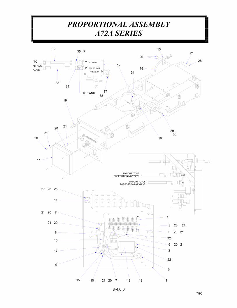
PROPORTIONAL ASSEMBLYA72A SERIES
8-4.0.07/96
16
9
17
21
21 20
8
20
7
14
27 26
11
25
2021
2120
NTROLALVE
TO
19
3334
33
715 10 21 20
I.B. U
P -
1
RO
T. C
W. -
5
O.B
. UP
- 3
O.B
. DO
WN
- 4
I.B. D
OW
N -
2
RO
T. C
CW
. - 6
1 - G
RE
EN
2 - R
ED
/BLK
3 - B
LAC
K
4 - O
RA
NG
E
6 - B
LUE
5 - R
ED
19 18
7 - G
RE
EN/B
LK
21 -
BLU
E/BL
K
19 -
BLU
E/W
HT
22 -
FUTU
RE
US
E
10 -
GR
N/W
HT
12 -
BLU
E/R
ED
13 -
WH
ITE
/RE
D
11 -
OR
AN/R
ED
EX
T. O
UT
- 7
EX
T. IN
- 8
AU
X 1
B -
10
AU
X 2
A -
11
AU
X 2
B -
12
AU
X 1
A -
9
8 - O
RA
N/B
LK
9 - R
ED
/WH
T
14 -
WH
ITE
DIN
GN
D -
16
STO
P R
ELA
Y -
20
STA
RT
RE
LAY
- 19
AM
P G
ND
- 18
PBS
GN
D -
17
AM
P T
RIG
GE
R -
21
FUTU
RE
US
E -
22
17 -
GR
OU
ND
18 -
BLK
/WH
T
20 -
BLK
/RED
P/N
369
176
21
1
9
6
22
2
20
21
4
32
5
3
20
23 24
16
13
PORPORTIONING VALVE
PORPORTIONING VALVETO PORT "C" OF
TO PORT "T" OF
PRESS. OUT
PRESS. IN
TO TANK
TO TANK
C
T
3738
P
3635
20
12
3118
IN
OUT
3029
28
21

PROPORTIONAL ASSEMBLYA72A SERIES
8-4.1.07/96
ADAPTER, X-LONG -12 OR(M) / -12 JIC
WASHER, SP LK #8NUT, #8-NC
WASHER, SP LK 3/8
NUT, HX LK 1/4-NC
HOSE ASSEMBLY
TIE WRAPCAP, NUT -12 JIC
SCREW, RD HD #8-NC X 7/8
SCREW, HX HD 3/8-NC X 4
WIRE ASSEMBLY, GROUNDWASHER, FLAT SAE 3/8
TEE, -12 OR(M) / -12 JIC
ELL, 90° -12 OR(M) / -12 JICELL, 90° -12 JIC SWIVEL / -12 JIC
13839 4
37363534
1111
750419634401
750469
367283750418
750421
229
313233
30612
2
28272625
21088
811023021100021200372289
812411-028
001205
019700015500
016300
GROMMET
CABLE CLAMP
BRACKETPROPORTIONING VALVECOVER, PROPORTIONAL
CAP, RECEPTACLE
GROMMET
WASHER, SP LK 1/4
WASHER, SP LK #6
RELAY, POWER ASSEMBLY
DIN CONNECTOR ASSEMBLYWIRE ASSEMBLY (POWER)
RECEPTACLE ASSEMBLY (CURB)WIRING HARNESS (SOLENOIDS)
SCREW, HX HD 1/4-NC X 3/4RECEPTACLE ASSEMBLY (STREET)
SCREW, RD HD #6-NC X 1/2SCREW, RD HD #8-NC X 1/2
1420
22
2423
212
2.2
14
1819
1716
11
11
005500020200001302000603019600
372293372296372297372298
111
1514
1213
12
11
910
87
32
13
372284
369171480547
372040
372295
480024372292370186750734
RELAY ASSEMBLYRELAY ASSEMBLY
PROPORTIONAL AMPLIFIER ASSEMBLYPROPORTIONAL PLATE WELDMENT
DECAL, TERMINAL BLOCK22 STATION TERMINAL BLOCK
12
6543
1111
ITEM
1 1
QTY.
372294
369176480494
372288372287
PART NO.
372281
DESCRIPTION
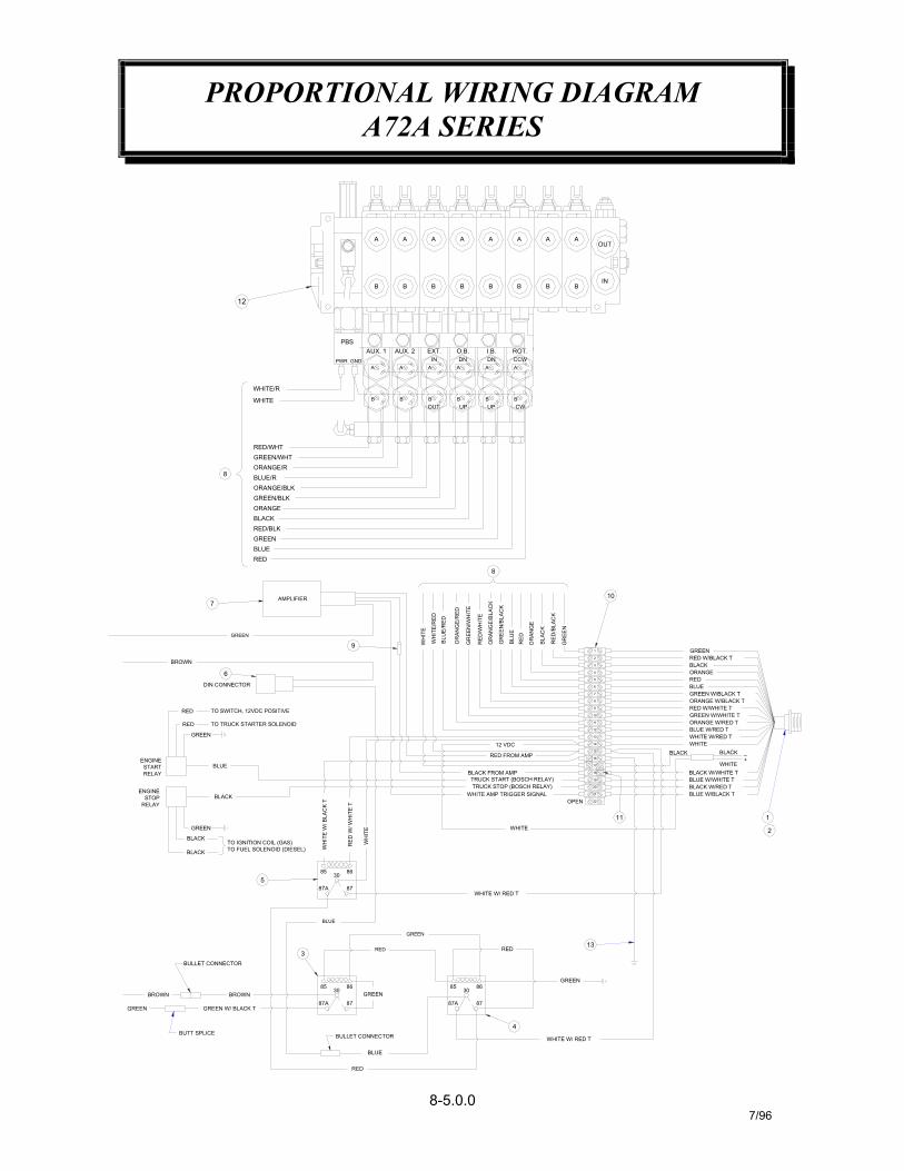
PROPORTIONAL WIRING DIAGRAMA72A SERIES
8-5.0.07/96
2
GREEN
13
BLACK
22
20
21
18
19
16
17
WHITE
OPEN
11
15
13
12
14
11
8
9
10
7
5
6
6
BLACK FROM AMP
WHITE W/ RED T
TRUCK STOP (BOSCH RELAY)TRUCK START (BOSCH RELAY)
WHITE AMP TRIGGER SIGNAL
RED
RED FROM AMP
12 VDC
3085 86
3085 86
GREEN87A
GREEN W/ BLACK T
BROWN
BUTT SPLICE
BROWN
RED
BULLET CONNECTOR
BLUE
GREEN87 87A 87
ENGINE
ENGINE
RELAY
RED
W/ W
HIT
E T
WH
ITE
W/ B
LAC
K T
WH
ITE
BLUE
87A
85
BULLET CONNECTOR
3
TO IGNITION COIL (GAS)TO FUEL SOLENOID (DIESEL)
BLACK
BLACK
5
GREEN
RED
86
87
30
STOP
GREEN
BLACK
RELAYSTART BLUE
DIN CONNECTOR
TO TRUCK STARTER SOLENOID
TO SWITCH, 12VDC POSITIVE
RED
GREEN
RED
4
WHITE W/ RED T
BLACK
BLUE W/BLACK T
1
BLUE W/WHITE TBLACK W/RED T
BLACK W/WHITE TWHITE
_+
GREEN W/WHITE TORANGE W/RED TBLUE W/RED TWHITE W/RED TWHITE
GREEN W/BLACK TORANGE W/BLACK TRED W/WHITE T
BLUERED
BLACK
AMPLIFIER
GREEN
BROWN
7
RED
RED/BLKGREENBLUE
9 BLU
E/R
ED
WH
ITE
/RE
D
WH
ITE
RE
D/W
HIT
E
GR
EEN
/WH
ITE
OR
AN
GE/
RED
GR
EE
N/B
LAC
K
OR
AN
GE
/BLA
CK
8
8 BLUE/R
GREEN/BLKORANGE/BLK
ORANGE
ORANGE/RGREEN/WHTRED/WHT
WHITE
WHITE/RB B
A A
UPOUT UPB B
A A
B
A
12
B B B B B
AUX. 2AUX. 1PBS
PWR GND DNO.B.EXT.
INI.B.DN
A A A A A
10
4
3
2
BLU
E
RE
D
RE
D/B
LAC
K
OR
AN
GE
BLA
CK
GR
EEN
1
RED W/BLACK T
ORANGEBLACK
GREEN
CWB
A
B B B
ROT.CCW
A A AOUT
IN
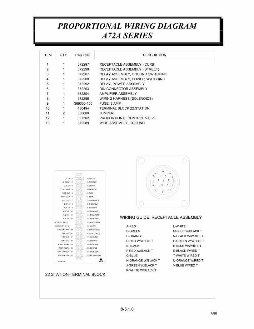
PROPORTIONAL WIRING DIAGRAMA72A SERIES
8-5.1.07/96
13 1 372289 WIRE ASSEMBLY, GROUND
10 - GRN/WHTAUX 1 B - 10
22 - FUTURE USEFUTURE USE - 22
22 STATION TERMINAL BLOCK
P/N 369176
12 - BLUE/RED
13 - WHITE/RED
18 - BLK/WHT
17 - GROUND
21 - BLUE/BLK
20 - BLK/RED
19 - BLUE/WHT
STOP RELAY - 20
AMP TRIGGER - 21
START RELAY - 19
DIN GND - 16
AMP GND - 18
PBS GND - 17
14 - WHITE
11 - ORAN/REDAUX 2 A - 11
AUX 2 B - 12
PBS/AMP PWR - 15
G-BLUE T-WHITE W/RED TU-ORANGE W/RED TH-ORANGE W/BLACK T
K-WHITE W/BLACK TJ-GREEN W/BLACK T V-BLUE W/RED T
WIRING GUIDE, RECEPTACLE ASSEMBLY
N-BLACK W/WHITE TM-BLUE W/BLACK T
S-BLACK W/RED TR-BLUE W/WHITE TP-GREEN W/WHITE T
F-RED W/BLACK T
D-RED W/WHITE TE-BLACK
B-GREENC-ORANGE
A-RED L-WHITE
2 - RED/BLK
4 - ORANGE
9 - RED/WHT
8 - ORAN/BLK
7 - GREEN/BLK
6 - BLUEROT. CCW. - 6
EXT. OUT - 7
EXT. IN - 8
AUX 1 A - 9
I.B. UP - 1
O.B. UP - 3
I.B. DOWN - 2
ROT. CW. - 5
O.B. DOWN - 4
3 - BLACK
5 - RED
1 - GREEN
H
FG E
J T
S
K U
CPV
R D
NB
ML A
RECEPTACLE ASSEMBLY, (STREET)RECEPTACLE ASSEMBLY, (CURB)
RELAY ASSEMBLY, POWER SWITCHINGRELAY ASSEMBLY, GROUND SWITCHING
DIN CONNECTOR ASSEMBLY
WIRING HARNESS (SOLENOIDS)
PROPORTIONAL CONTROL VALVE
TERMINAL BLOCK 22 STATION
RELAY, POWER ASSEMBLY
JUMPER
AMPLIFIER ASSEMBLY
FUSE, 8 AMP
4 1 37228837229215
1112
10 4804941
12
367302636600
369300-10098
11
76
11
372296
372293372294
ITEM
1321
11
372287
372297372298
QTY. PART NO. DESCRIPTION
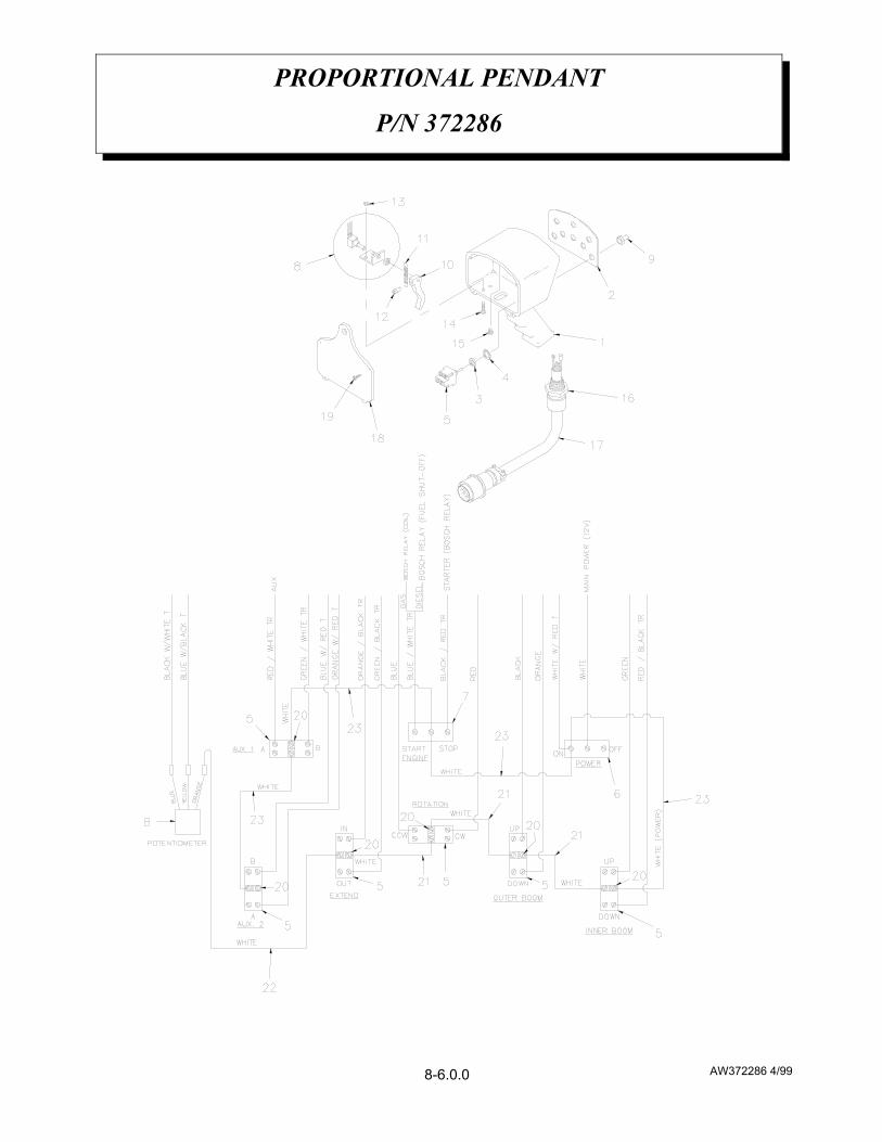
AW372286 4/99
PROPORTIONAL PENDANT
P/N 372286
8-6.0.0

AW372286 4/99
PROPORTIONAL PENDANT
P/N 372286
WHITE CONDUCTOR ASSEMBLY480526123WHITE CONDUCTOR ASSEMBLY480524122WHITE CONDUCTOR ASSEMBLY660302321JUMPER636600620ROUND HEAD SCREW #6 x 3/4480516419BACK PLATE HOUSING480504118PENDANT CABLE 480514117CONNECTOR480567116PAN HEAD SCREW #8 x 3/8005003115SCREW #10-24 NC x 3/4002607214HEX LOCK NUT #10-24 NC015801213SOCKET HEAD SCREW #10-32 NF x 5/8480517112TRIGGER RETURN SPRING480523111TRIGGER480506110TOGGLE BOOT64030089POTENTIOMETER ASSEMBLY48050718SPDT TOGGLE SWITCH62200017ON/OFF TOGGLE SWITCH 75009016DPDT TOGGLE SWITCH 63420065WASHERREF84NUTREF83PROPORTIONAL PENDANT DECAL36818612PROPORTIONAL PENDANT48050111DESCRIPTIONP/NQTYITEM
8-6.1.0

KNUCKLEBOOM PROPORTIONAL PENDANTTRIGGER POTENTIOMETER SETUP PROCEDURE
8-7.0.09/96
1 Position the truck with crane in a safe workarea. Using hand levers on the control valve,extend outriggers out and down, unfoldbooms, rotate crane until booms are directlyover bed of truck.
2 Remove amplifier terminal block coverlocated on the base of crane.
3 Plug pendant into one of the receptacleslocated on either side of crane.
4 Turn power on.5 Check the output voltage of the pendant
trigger potentiometer with trigger pulled,voltage output should be 3.0 to 9.0 volts onterminal #21. Check with trigger released,voltage output should be 0.4 to 0.6 volts onterminal #21. If trigger potentiometer outputfalls in the voltage range specified no otheradjustment to the pendant triggerpotentiometer is required. If triggerpotentiometer output does not fall within thevoltage ranges specified continue with setupprocedure.
6 Remove four (4) screws which hold pendantback plate on, and remove back plate.
7 Make sure potentiometer's mounting nut istight.
8 Loosen (do not remove) the 5/32" allen headcap screw that locks the trigger in place.
9 With trigger released, turn the potentiometershaft full counterclockwise with a screwdriver,then slowly turn shaft clockwise to achieve 0.4to 0.6 volts on terminal #21.
NOTE: CARE SHOULD BE TAKENWHEN HANDLING THEPOTENTIOMETER ASSEMBLY TOKEEP FROM BREAKING THE WIRESAT THEIR ATTACHMENT POINTS.
Tighten the allen head screw using a 5/32"allen wrench (DO NOT OVER TIGHTEN).This screw need only be set firmly againstpotentiometer shaft. Trigger damage willresult from over tightening. Retest voltage onterminal #21.
10 Fully pull trigger and verify that there is 3.0 to9.0 on terminal #21.
11 Slowly pull trigger through a full cycle (fullyreleased to fully pulled) to verify consistentsmooth voltage change at terminal #21.Replace potentiometer assembly if voltagechange is not smooth.
12 Replace pendant and amplifier-terminal blockcovers.
13 Stow crane, turn power "OFF", unplug andstore pendant.
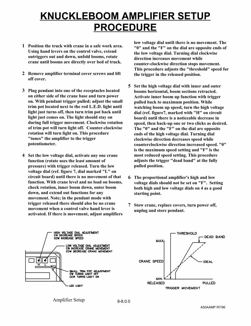
1 Position the truck with crane in a safe work area.Using hand levers on the control valve, extendoutriggers out and down, unfold booms, rotatecrane until booms are directly over bed of truck.
2 Remove amplifier terminal cover screws and liftoff cover.
3 Plug pendant into one of the receptacles locatedon either side of the crane base and turn poweron. With pendant trigger pulled; adjust the smalltrim pot located next to the red L.E.D. light untillight just turns off, then turn trim pot back untillight just comes on. The light should stay onduring full trigger movement. Clockwise rotationof trim pot will turn light off. Counter-clockwiserotation will turn light on. This procedure"tunes" the amplifier to the triggerpotentiometer.
4 Set the low voltage dial, activate any one cranefunction (rotate uses the least amount ofpressure) with trigger released. Turn the lowvoltage dial (ref. figure 7, dial marked "L" oncircuit board) until there is no movement of thatfunction. With crane level and no load on booms,check rotation, inner boom down, outer boomdown, and extend out functions for anymovement. Note; in the pendant mode withtrigger released there should also be no cranemovement when a control valve hand lever isactivated. If there is movement, adjust amplifiers
low voltage dial until there is no movement. The"0" and the "F" on the dial are opposite ends ofthe low voltage dial. Turning dial clockwisedirection increases movement whilecounter-clockwise direction stops movement.This procedure adjusts the "threshold" speed forthe trigger in the released position.
5 Set the high voltage dial with inner and outerbooms horizontal, boom sections retracted.Activate inner boom up function with triggerpulled back to maximum position. Whilewatching boom up speed, turn the high voltagedial (ref. figure7, marked with "H" on circuitboard) until there is a noticeable decrease inspeed, then back-up one or two clicks as desired.The "0" and the "F" on the dial are oppositeends of the high voltage dial. Turning dialclockwise direction decreases speed whilecounterclockwise direction increased speed. "0"is the maximum speed setting and "F" is themost reduced speed setting. This procedureadjusts the trigger "dead band" at the fully pulled position.
6 The proportional amplifier's high and lowvoltage dials should not be set on "F". Settingboth high and low voltage dials on 4 as a goodstarting point.
7 Stow crane, replace covers, turn power off,unplug and store pendant.
KNUCKLEBOOM AMPLIFIER SETUPPROCEDURE
A50AAMP R7/96
Amplifier Setup 8-8.0.0

HAND HELD PENDANT ASSEMBLY1. With ignition key in the "ON" position, hand held
pendant assembly plugged into system, and pendantpower on-off switch in the "ON" position;
A.Check pendant trigger signal voltage atterminal #21. Voltage should be 3.0 to 9.0volts when pendant trigger is pulled, 0.4 to0.6 volts when pendant trigger is released.
B. Test trigger potentiometer output voltage atterminal #21 for consistent smooth voltagechange when trigger is pulled. NOTE: for Aand B reference pendant trigger potentiome-ter setup procedure.
2. Check pendant trigger for damage which may haveoccurred from over tightening of set screw.
3. Verify all wiring to pendant switches is correct andthat there are no loose connections.
PROPORTIONAL FLOW CONTROL VALVE
1. Check voltage at terminals #13, #14, #15.
A.Terminal #13 voltage should be 12 VDCnominal when pendant is plugged intosystem and the on-off power switch isturned to the "ON" position.
B. Terminal #14 voltage should be 12 VDCnominal when master switch is in the "ON"position.
C.Terminal #15 voltage should be 12 VDCnominal when there is 12 VDC at terminals#13 and #14.
2. With 12 VDC nominal applied to terminal #15,disconnect brown wire from DIN connector (groundbrown wire) to shift proportional valve full on.
3. Measure proportional flow control valve's coil resis-tance; turn ignition key and master switch to the"OFF" position to remove power from proportionalsystem. Disconnect brown and blue wire bulletconnectors from proportional flow control valves coil. Measure resistance between brown and blue bulletconnectors. Coil resistance should be 4.5-5.5 ohms. Ifresistance is outside that range, replace coil.
4. To check hydraulic flow to crane:
A.Engage PTO-pump, turn manual overrideclockwise to divert pressure and flow todirectional control valve. Crane shouldoperate manually.
B. Place flow meter in the tank line from theproportional flow control valve. Measureflow with pendant plugged in and systemturned on, trigger released. Flow to tankshould be 9-13 gpm, depending on model ofcrane. As trigger is pulled, flow shouldsmoothly decrease to 0 gpm.
1
5. Measure voltage drop across proportional flowcontrol valve's coil. Voltage may be measured using adigital volt-ohm meter set to volts. Check voltagebetween terminal #15 and the bullet connector, withthe pendant plugged in and turned on. The bulletconnector is the connector on the brown wire of theDIN connector from proportional flow control valve'scoil. IMPORTANT: Bullet connector must remainconnected when taking voltage readings. Voltage dropshould be 12 VDC nominal with pendant triggerpulled to less than 1 VDC nominal with pendanttrigger released. Note: to register these readingssystem must be turned on, (i.e., with red L.E.D. lighton). The settings of the amplifier's high and lowvoltage dials affects both the 12 VDC and 1 VDCnominal voltage readings across the coil of theproportional flow control valve. Normally, both thehigh and low voltage dials are adjusted to 4.
TROUBLE SHOOTING PROPORTIONALCONTROL SYSTEM
9/948-9.0.0
FIG. 8
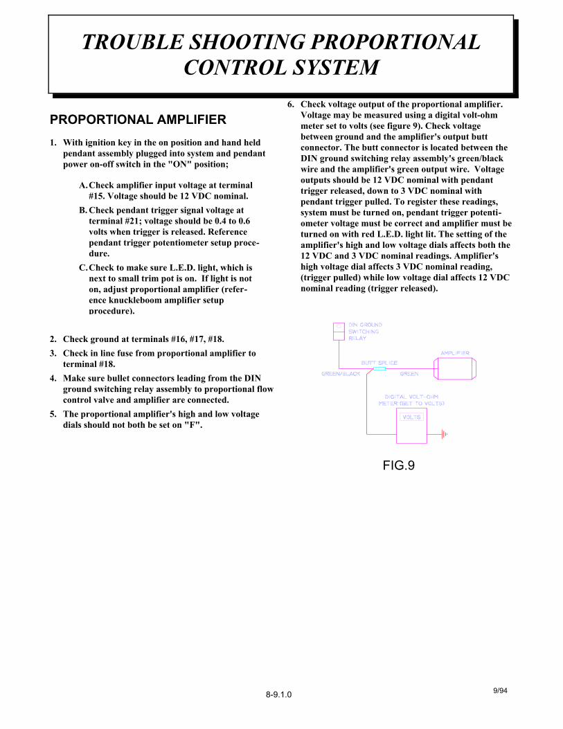
PROPORTIONAL AMPLIFIER1. With ignition key in the on position and hand held
pendant assembly plugged into system and pendantpower on-off switch in the "ON" position;
A.Check amplifier input voltage at terminal#15. Voltage should be 12 VDC nominal.
B. Check pendant trigger signal voltage atterminal #21; voltage should be 0.4 to 0.6volts when trigger is released. Referencependant trigger potentiometer setup proce-dure.
C.Check to make sure L.E.D. light, which isnext to small trim pot is on. If light is noton, adjust proportional amplifier (refer-ence knuckleboom amplifier setupprocedure).
2. Check ground at terminals #16, #17, #18. 3. Check in line fuse from proportional amplifier to
terminal #18. 4. Make sure bullet connectors leading from the DIN
ground switching relay assembly to proportional flowcontrol valve and amplifier are connected.
5. The proportional amplifier's high and low voltagedials should not both be set on "F".
6. Check voltage output of the proportional amplifier.Voltage may be measured using a digital volt-ohmmeter set to volts (see figure 9). Check voltagebetween ground and the amplifier's output buttconnector. The butt connector is located between theDIN ground switching relay assembly's green/blackwire and the amplifier's green output wire. Voltageoutputs should be 12 VDC nominal with pendanttrigger released, down to 3 VDC nominal withpendant trigger pulled. To register these readings,system must be turned on, pendant trigger potenti-ometer voltage must be correct and amplifier must beturned on with red L.E.D. light lit. The setting of theamplifier's high and low voltage dials affects both the12 VDC and 3 VDC nominal readings. Amplifier'shigh voltage dial affects 3 VDC nominal reading,(trigger pulled) while low voltage dial affects 12 VDCnominal reading (trigger released).
9/94
TROUBLE SHOOTING PROPORTIONALCONTROL SYSTEM
FIG.9
8-9.1.0
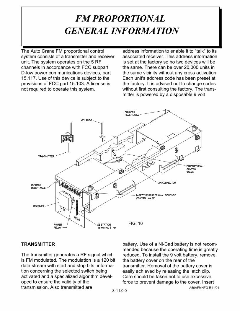
The Auto Crane FM proportional controlsystem consists of a transmitter and receiverunit. The system operates on the 5 RFchannels in accordance with FCC subpartD-low power communications devices, part15.117. Use of this device is subject to theprovisions of FCC part 15.103. A license isnot required to operate this system.
TRANSMITTER
The transmitter generates a RF signal whichis FM modulated. The modulation is a 120 bitdata stream with start and stop bits, informa-tion concerning the selected switch beingactivated and a specialized algorithm devel-oped to ensure the validity of thetransmission. Also transmitted are
address information to enable it to "talk" to itsassociated receiver. This address informationis set at the factory so no two devices will bethe same. There can be over 20,000 units inthe same vicinity without any cross activation.Each unit's address code has been preset atthe factory. It is advised not to change codeswithout first consulting the factory. The trans-mitter is powered by a disposable 9 volt
battery. Use of a Ni-Cad battery is not recom-mended because the operating time is greatlyreduced. To install the 9 volt battery, removethe battery cover on the rear of thetransmitter. Removal of the battery cover iseasily achieved by releasing the latch clip.Care should be taken not to use excessiveforce to prevent damage to the cover. Insert
FM PROPORTIONAL GENERAL INFORMATION
FIG. 10
8-11.0.0A50AFMNFO R11/94
the battery making sure the polarity of theterminals are correct.
RECEIVER
Receiver receives a the signal transmitted bythe transmitter, decodes the data stream andchecks for validity of the address and the startand stop bits of the received data. If this iscorrect, a proprietary software algorithm isperformed to accept or reject the informationto be passed on to the outputs. If for anyreason this test fails, no output will be allowedto function. Once this test has passed, theappropriate output will be activated.
RECEIVER CONNECTOR INSTRUCTIONS
Insert a small straight blade screwdriver intothe square hole of the desired pin. Pryingtowards the face (lid) of the receiver, insert orremove the appropriate wire directly belowscrewdriver. Release the screwdriver and theconnection is complete. strip all wires to beinserted into the 20 pin connector to a lengthof 3/8" to 1/2" long. Wires should be tinned forease of installation. There are three (3) inputsto the receiver; BNC connector Positive D.C.current Negative ground The unit derivespower from a 12 vdc nominal power sourcethat is negative ground. First hook up powerinputs to receiver. It is required to install apower switch for the receiver in series (in-line)with the D.C. power system (battery).
INITIALIZING UNIT
When initially using the radio remote controlsystem, turn power on the receiver first. Thisallows power to the micro processor andawaits for a special code from the transmitterto activate a relay to make power available to
the output driver circuit. When the transmitteris turned on, it will transmit a special code for10 seconds to instruct the receiver to initialize.This will happen only if the transmitter is nottransmitting a function such as a switch beingactivated. During this initial 10 seconds afunction may be activated once the receiverhas been initialized. The initialization is instan-taneous so operator will not have any delay inoperation. If the transmitter is "out of range" ora function is activated when the transmitter isturned on, the receiver will not be initialized.Once the receiver has been initialized, theunit will be allowed to operate.
EMERGENCY KILL FUNCTION
Each transmitter is equipped with anemergency kill switch located near theantenna which when activated will "shutdown" the receiver and stop truck engine.This must be activated while transmitterpower is in the "on" position. This specialcode will be transmitted for a period of 10seconds. when the receiver receives thisspecial code, the power to the output drivercircuit will be de-activated. To resume opera-tion, the transmitter must again send thespecial code to re-activate the receiver. Toachieve this, turn transmitter power off andback on. The transmitter will again go throughits routine to initialize the receiver pleaseinstruct your operators how to use the"emergency kill" and insist that they operatethis feature to become familiar with theoperation.
ADDRESS CODES
Each transmitter and receiver's address codeare unique and preset at factory. We advisethat the codes not be changed without firstconsulting the factory. There are two featuresin our system that the end user can change to
FM PROPORTIONAL GENERAL INFORMATION
8-11.1.0A50AFMNFO R11/94

NOTES
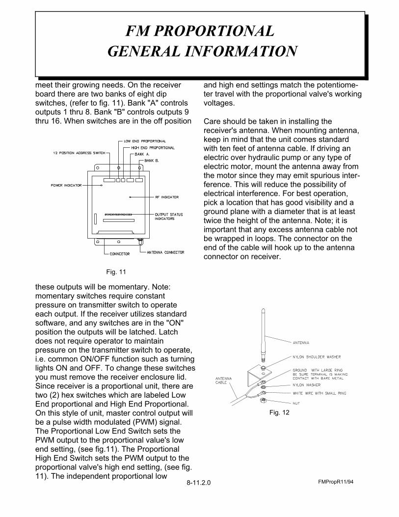
meet their growing needs. On the receiverboard there are two banks of eight dipswitches, (refer to fig. 11). Bank "A" controlsoutputs 1 thru 8. Bank "B" controls outputs 9thru 16. When switches are in the off position
these outputs will be momentary. Note:momentary switches require constantpressure on transmitter switch to operateeach output. If the receiver utilizes standardsoftware, and any switches are in the "ON"position the outputs will be latched. Latchdoes not require operator to maintainpressure on the transmitter switch to operate,i.e. common ON/OFF function such as turninglights ON and OFF. To change these switchesyou must remove the receiver enclosure lid.Since receiver is a proportional unit, there aretwo (2) hex switches which are labeled LowEnd proportional and High End Proportional.On this style of unit, master control output willbe a pulse width modulated (PWM) signal.The Proportional Low End Switch sets thePWM output to the proportional value's lowend setting, (see fig.11). The ProportionalHigh End Switch sets the PWM output to theproportional valve's high end setting, (see fig.11). The independent proportional low
and high end settings match the potentiome-ter travel with the proportional valve's workingvoltages.
Care should be taken in installing thereceiver's antenna. When mounting antenna,keep in mind that the unit comes standardwith ten feet of antenna cable. If driving anelectric over hydraulic pump or any type of electric motor, mount the antenna away fromthe motor since they may emit spurious inter-ference. This will reduce the possibility ofelectrical interference. For best operation,pick a location that has good visibility and aground plane with a diameter that is at leasttwice the height of the antenna. Note; it isimportant that any excess antenna cable notbe wrapped in loops. The connector on theend of the cable will hook up to the antennaconnector on receiver.
FM PROPORTIONAL GENERAL INFORMATION
8-11.2.0
Fig. 11
FMPropR11/94
Fig. 12
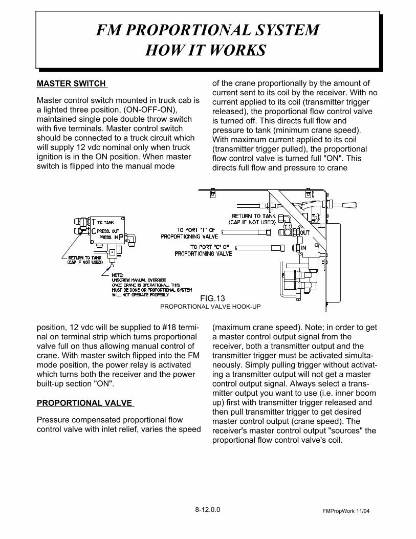
MASTER SWITCH
Master control switch mounted in truck cab isa lighted three position, (ON-OFF-ON),maintained single pole double throw switchwith five terminals. Master control switchshould be connected to a truck circuit whichwill supply 12 vdc nominal only when truckignition is in the ON position. When masterswitch is flipped into the manual mode
position, 12 vdc will be supplied to #18 termi-nal on terminal strip which turns proportionalvalve full on thus allowing manual control ofcrane. With master switch flipped into the FMmode position, the power relay is activatedwhich turns both the receiver and the powerbuilt-up section "ON".
PROPORTIONAL VALVE
Pressure compensated proportional flowcontrol valve with inlet relief, varies the speed
of the crane proportionally by the amount ofcurrent sent to its coil by the receiver. With nocurrent applied to its coil (transmitter triggerreleased), the proportional flow control valveis turned off. This directs full flow andpressure to tank (minimum crane speed).With maximum current applied to its coil(transmitter trigger pulled), the proportionalflow control valve is turned full "ON". Thisdirects full flow and pressure to crane
(maximum crane speed). Note; in order to geta master control output signal from thereceiver, both a transmitter output and thetransmitter trigger must be activated simulta-neously. Simply pulling trigger without activat-ing a transmitter output will not get a mastercontrol output signal. Always select a trans-mitter output you want to use (i.e. inner boomup) first with transmitter trigger released andthen pull transmitter trigger to get desiredmaster control output (crane speed). Thereceiver's master control output "sources" theproportional flow control valve's coil.
FMPropWork 11/94
FM PROPORTIONAL SYSTEMHOW IT WORKS
FIG.13PROPORTIONAL VALVE HOOK-UP
8-12.0.0
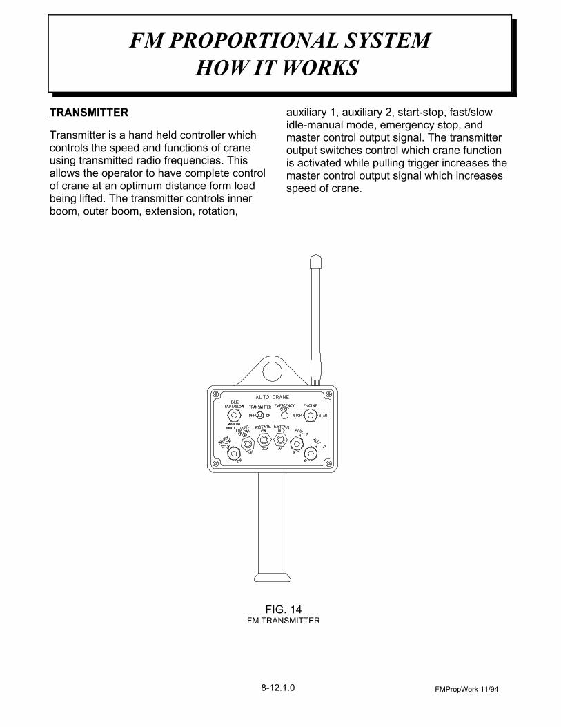
TRANSMITTER
Transmitter is a hand held controller whichcontrols the speed and functions of craneusing transmitted radio frequencies. Thisallows the operator to have complete controlof crane at an optimum distance form loadbeing lifted. The transmitter controls innerboom, outer boom, extension, rotation,
auxiliary 1, auxiliary 2, start-stop, fast/slowidle-manual mode, emergency stop, andmaster control output signal. The transmitteroutput switches control which crane functionis activated while pulling trigger increases themaster control output signal which increasesspeed of crane.
FMPropWork 11/94
FM PROPORTIONAL SYSTEMHOW IT WORKS
FIG. 14FM TRANSMITTER
8-12.1.0

1 Make sure all crane operating personnelhave thoroughly read and understoodthe information contained in thismanual. Crane to be operated by quali-fied personnel only.
2 A routine daily inspection of the craneshould be mandatory before eachoperating day. Any defect should becorrected immediately before operatingthe crane.
3 At a job site the vehicle should bepositioned so that the crane can beadequately reach the load within therated capacity (centerline of rotation tohook). Job site should be checked forany hazards which might create anunsafe situation for the operator suchas overhead electrical lines, under-ground electrical lines, any electricalsources, soft or uneven ground, andany unauthorized personnel who mightenter the job site. When cross gradeparking is necessary, restrict the load tocompensate for the increased tippingrisk of the vehicle.
4 Keep vehicle as level as possible duringoperation.
5 Chock rear wheels, engage emergencybrake, place gear selector into neutral,press clutch and PTO knob in gear,release clutch and set throttle control toproper engine speed.
WARNING: DO NOT EXCEEDENGINE SPEED NECESSARY TOMEET PUMP RPM REQUIREMENT,POSSIBLE DAMAGE MAY RESULT.
6 System has two operational modes: 1.)manual control 2.) FM control. In the
manual mode operator will have manualcontrol of all crane functions,outriggers, and auxiliary valve sections.While in the FM mode, operator willhave control of crane functions only.There are two ways an operator mayselect to operate crane in the manualmode; First, move master control switchin cab into the manual mode position.Second, move master control switchinto the FM mode position, turn trans-mitter power on and activate transmittermanual mode switch. NOTE; While inthis mode the operator will have manualcontrol of crane until any transmitteroutput function is activated which willautomatically switch transmitter frommanual control to FM control. Tooperate crane in the FM mode movemaster control switch into the FM modeposition, turn transmitter power on, theoperator will have control of cranetransmitter only. The hand held trans-mitter will operate all crane functionsexcept outriggers.
7 Begin by selecting FM mode mastercontrol switch, turn transmitter poweron, activate the manual mode switch onthe transmitter, this will allow manualcontrol of crane to set outriggers.Always use outriggers from crane to theground. Be sure outriggers are in firmcontact with ground and are adequatelypositioned. Once outriggers have beenproperly set, the operator may continueto operate the crane in the manual modeor may choose to operate crane in theFM mode. To switch crane to FM modethe operator may de-activate transmittermanual mode switch or activate anytransmitter output function. To operateFM transmitter properly always selectthe crane function you want to use (i.e.
inner boom up) first with the
OPERATION OF KNUCKLEBOOM WITHFM PROPORTIONAL REMOTE CONTROL
8-13.0.0 FMPropOp 11/94

transmitter trigger released and thenpull transmitter trigger to get desiredcrane speed.
8 When unstowing knuckleboom crane,first begin by retracting outer boomcylinder, which raises the outer boomup in the ramp and purges any air out ofthe outer boom cylinder. Extend liftcylinder to raise inner boom. Once innerboom is clear of the base, the crane canbe rotated into a work ready position.Always raise inner boom up beforerotating.
9 Always observe safe and practicaloperating practices to avoid possibleaccidents. Refer to "SAFETY TIPS ANDPRECAUTIONS".
10After completing lifting operations,return the booms to the figure 4 positionfor travel. When stowing, begin byretracting the extension cylinder.Retract outer boom cylinder. Rotatecrane into position by aligning up therotation arrows on the rotation bearingand base plate. Retract lift cylinder to
lower inner boom into the figure 4position. Always stand on the oppositeside of the inner boom when stowingand unstowing.
11Once the crane has been properlystowed, return FM system to manualmode and return out outriggers to thestowed position. Make sure outriggersare pinned in place (if required) fortravel.
12Turn both the transmitter power switch,and the master control switch (in cab) tothe "OFF" position. Never leave trans-mitter on, and always store transmitterin proper place when not in use.
13Check job site for any tools or equip-ment not stored. Store all wheel chocks.
14Press clutch and disengage PTO.Release throttle control and emergencybrake.
15report any unusual occurrence duringcrane operation that may indicaterequired maintenance or repair.
OPERATION OF KNUCKLEBOOM WITHFM PROPORTIONAL REMOTE CONTROL
FMPropOp 11/948-13.1.0
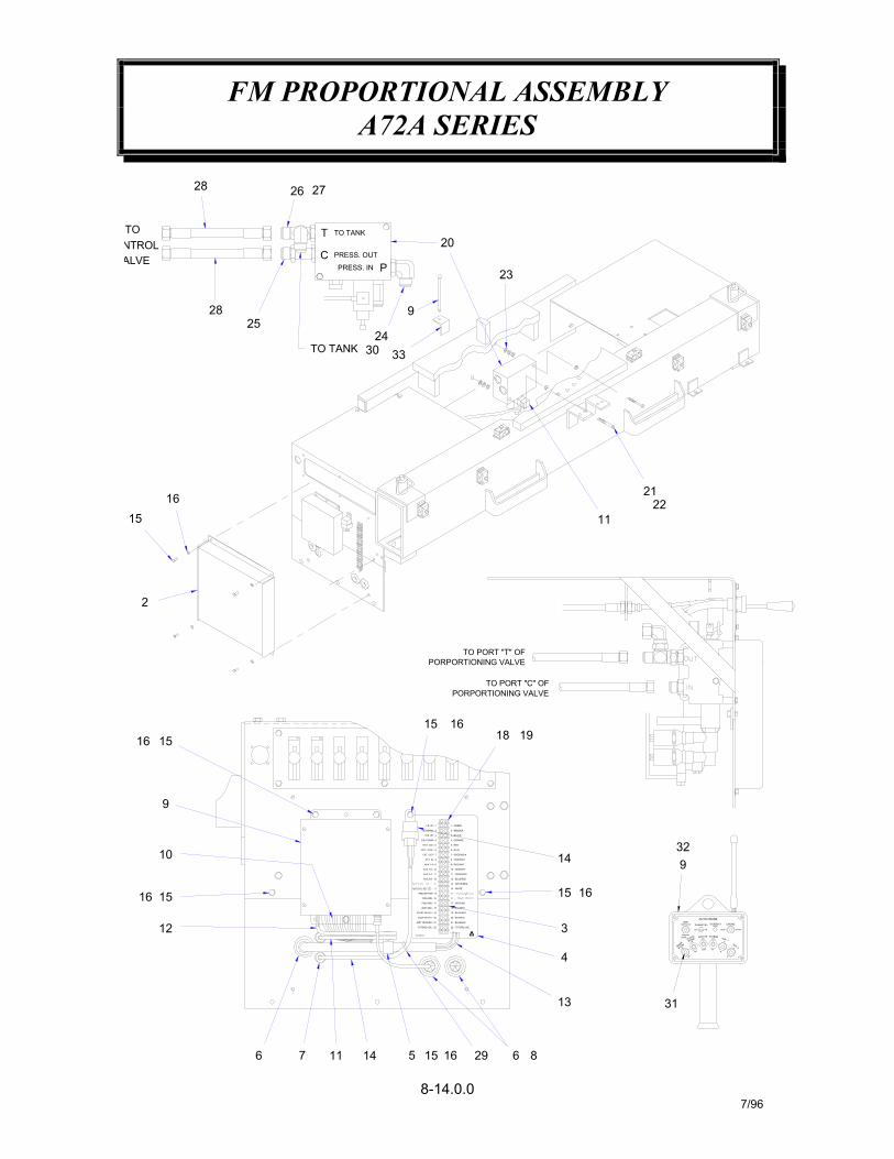
FM PROPORTIONAL ASSEMBLYA72A SERIES
8-14.0.07/96
31
10
1516
12
9
16 15
2
16116 7 14 5 15 29 6 8
13
4
PORPORTIONING VALVE
AMP TRIGGER - 21
FUTURE USE - 22
P/N 369176
STOP RELAY - 20
START RELAY - 19
PBS GND - 17
AMP GND - 18
DIN GND - 16
AUX 2 A - 11
AUX 2 B - 12
AUX 1 B - 10
EXT. IN - 8
AUX 1 A - 9
EXT. OUT - 7
O.B. DOWN - 4
ROT. CW. - 5
ROT. CCW. - 6
I.B. DOWN - 2
O.B. UP - 3
I.B. UP - 1
15
20 - BLK/RED
22 - FUTURE USE
21 - BLUE/BLK
17 - GROUND
19 - BLUE/WHT
18 - BLK/WHT
11 - ORAN/RED
14 - WHITE
13 - WHITE/RED
12 - BLUE/RED
8 - ORAN/BLK
10 - GRN/WHT
9 - RED/WHT
7 - GREEN/BLK
4 - ORANGE
2 - RED/BLK
5 - RED
6 - BLUE
3 - BLACK
1 - GREEN
1615
3
14
TO PORT "C" OFPORPORTIONING VALVE
1816
19
TO PORT "T" OF
TO
1615
NTROLALVE
28
28
TO TANKT20
PRESS. IN
TO TANK
PRESS. OUT
25
C
333024
P
9
21
1122
23
26 27
AUX. 1BOOMOUTEROUTCW
BDN
BOOMINNER
DN
UP
UP
CCW INA
AUX. 2
B
A
32
STOP
MANUALMODE
FAST/SLOWIDLE
AUTO CRANE
ONOFF
ROTATE EXTEND
9
ENGINE
START

FM PROPORTIONAL ASSEMBLYA72A SERIES
8-14.1.07/96
ELL, 90° -12 JIC / -12 JIC
BRACKET ANTENNA
HOSE ASSEMBLY
CAP, NUT -12 JIC
BATTERY, 9VBOOT, TOGGLE
TIE WRAP
31 8 640300
33 132 1
372371480605
29 430 1
2827
21
634401750419
812411-028367283
COVER, PROPORTIONAL WELDMENTPROPORTIONAL PLATE WELDMENT
22 STATION TERMINAL BLOCK
FM TRANSMITTER / RECEIVER SET
WIRING HARNESS, FM RECEIVER POWERDIN CONNECTOR ASSEMBLY, FMWIRING HARNESS RECEIVER
RELAY ASSEMBLY, FM POWERWIRING HARNESS, SOLENOIDS
SCREW, HX HD 1/4-NC X 3/4
SCREW, RD HD #6-NC X 1/2
SCREW, HX HD 3/8-NC X 4
ADAPTER, STR. X-LONG -12 OR(M) / -12 JICELL, 90° -12 OR(M) / -12 JIC
TEE, -12 OR(M) / -12 JIC
CABLE CLAMP
WASHER, SP LK #6PROPORTIONING VALVE
WASHER, FLAT 3/8WASHER, SP LK 3/8
WASHER, SP LK 1/4WASHER, FLAT 1/4
BUSHING, HEYCOGROMMETGROMMET
DECAL, TERMINAL BLOCK
372365110
2625
11
2423
16
750421750469750418021200
2221
22
2019
12
021100811023372040019600
14 1 372360
1817
24
1615
1111
000603020400020200005500
11213 1
11 1372363372296
372364
2 1 372284
6 3 370186
8 29 1
7 2372367372372
750734
4 15 1
3 1369176480024
480494
1 1
ITEM QTY.
372281
PART NO. DESCRIPTION
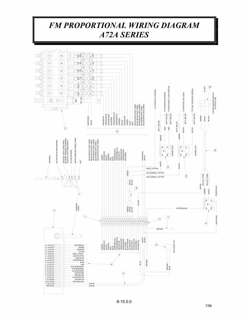
FM PROPORTIONAL WIRING DIAGRAMA72A SERIES
8-15.0.07/96
BLA
CK
12
BLACK\WHITE
WHITE\BLACKBLU\BLACK
BLACKWHITE
GREEN\WHITE
ORANGE\BLACKGREEN\BLACK
WHITE\REDRED\WHITE
ORANGE\RED
REDBLUE
BLUE \WHITEBLUE\RED
4
5
BLU
E
GR
EEN
WH
ITE
BLA
CK
BLACK \ RED
ORANGEBLACK
RED/BLACKGREEN
1
RED
\WH
ITE
RED
/BLA
CK
OR
AN
GE\
BLAC
KG
RE
EN\B
LAC
K
OR
ANG
E
GR
EEN
BLA
CK
BLU
ER
ED
BLU
E\R
ED
GR
EEN
\WH
ITE
OR
ANG
E\R
ED
BLA
CK
\WH
ITE
BLU
E\W
HIT
EBL
ACK
\RED
WH
ITE
\BLA
CK
WH
ITE\
RED
BLU
E\B
LAC
K
WH
ITE
1 32 64 5 97 8 1210 11 13 14 15 1716 18 2019
3 AN
TEN
NA
CAB
LE
BLA
CK
BLA
CK
WH
ITE
10
GR
EEN
BR
OW
N
BR
OW
N
BLU
E
6
BLA
CK
DIN
CO
NN
EC
TOR
BROWN
2221
2
7
8
WH
ITE
\RED
WHITE\BLACK
BULLET CONNECTOR
BULLET CONNECTOR
BULLET CONN.
13
GR
EEN
PO
WE
R R
ELA
Y
878685 87
A
30W
HIT
E
BU
LLE
T C
ON
N.
BU
LLE
T C
ON
N.
BLA
CK
WH
ITE
\RED
BLA
CK
\WH
ITE
(NO
T U
SED
)
OU
T
AA
RED
\WH
ITE
GR
EEN
\WH
ITE
OR
AN
GE\
RE
DB
LUE
\RED
OR
ANG
E\B
LAC
KG
REE
N\B
LAC
KO
RA
NG
EB
LAC
KR
ED\B
LAC
KG
REE
NB
LUE
RED
WH
ITE\
RED
WH
ITE
BLA
CK\
WH
ITE
(NO
T U
SED
)BL
UE\
BLA
CK
(NO
T U
SED
)W
HIT
E\B
LAC
K (N
OT
USE
D)
BLAC
K\R
ED (N
OT
US
ED)
BLAC
K\R
ED (N
OT
US
ED)
BLA
CK
\WH
ITE
(NO
T U
SED
)BL
UE\
BLA
CK
(NO
T U
SED
)W
HIT
E\B
LAC
K (N
OT
USE
D)
NYL
ON
SH
OU
LDE
R W
ASH
ER
GR
OU
ND
WIT
H L
AR
GE
RIN
GBE
SU
RE
TER
MIN
AL
IS M
AKIN
GC
ON
TAC
T W
ITH
BAR
E M
ETA
L
WH
ITE
WIR
E W
ITH
SM
ALL
RIN
G
NYL
ON
WAS
HE
R
ANTE
NN
A
NU
T
11
BLA
CK
\WH
ITE
(NO
T U
SED
)
RED
\WH
ITE
RED
\BLA
CK
OR
AN
GE
OR
ANG
E\B
LAC
KG
REE
N\B
LAC
K
BLA
CK
GR
EEN
BLU
ER
ED
BLU
E\R
EDO
RA
NG
E\R
EDG
RE
EN\W
HIT
E
9
PBS
PWR
BB
AU
X. 1
GN
DA B
AU
X. 2
A B
AA
AA
BB
B
EXT
.IN A
O.B
.D
NA
BU
PB
I.B.
DN
A UP
B
B
RO
T.C
CW
A CW
B
BU
TT S
PLIC
E
BUTT
SPL
ICE
BUTT
SPL
ICE
BUTT
SPL
ICE
BUTT
SPL
ICE
BUTT
SPL
ICE
EN
GIN
E ST
AR
T
WH
ITE
WH
ITE
3085
86
87A
87
3085 87
A
86 87
GR
EEN
RED
GR
EEN
RED
BLA
CK
EN
GIN
E S
TOP
14
BLA
CK
TO S
TAR
TER
SO
LEN
OID
TO S
WIT
CH
ED
12
VDC
PO
SITI
VE
TO IG
NIT
ION
CO
IL (G
AS)
TO T
HR
OTT
LE C
ON
TRO
L
TO F
UE
L SO
LEN
OID
(DIE
SEL)
LIG
HTE
D M
AST
ER S
WIT
CH
IN T
RU
CK
CAB
GR
EEN
WH
ITE
BLA
CK
12 V
DC 15

FM PROPORTIONAL WIRING DIAGRAMA72A SERIES
8-15.1.07/96
DESCRIPTION
RELAY ASSEMBLY, ENGINE STOPWIRING HARNESS, FM MASTER SWITCH
WIRING HARNESS, START/STOP SPLICE6-FUNCTION PROPORTIONAL CONTROL VALVERELAY ASSEMBLY, ENGINE START
RELAY ASSEMBLY, FM GROUNDWIRING HARNESS, (SOLENOIDS)
WIRE ASSEMBLY, FM GROUND
FM TRANSMITTER / RECEIVER SET
WIRING HARNESS, FM RECEIVER POWER
22 STATION TERMINAL BLOCK
1415
1312
9
1110
87
4
65
32
SWITCH, MASTER11
11
372362372366
372369372368
JUMPER
DIN CONNECTOR ASSEMBLY
WIRING HARNESS, RECEIVER
1
11
11
372296
367302372370
372360372361
1
11
13
372365
372364372363
372372636600
ITEM
1
PART NO.QTY.
1 480494

GENERAL
Whenever there is a problem with the systembegin by first checking the fuse in the receiverand then checking all wiring and connectors.Look for dead shorts in wiring andconnections, or run a new cable from theoutputs of the receiver directly to solenoidsand then try radio system. maximum 12 to 15amp fuse in receiver.
TRANSMITTING RANGE DROPS ORINTERMITTENT MOVEMENT OCCURSWHEN ACTIVATING A FUNCTION
1 Make sure the 9 volt battery in thetransmitter is good.
2 Be sure the antenna is free of verticalmetal obstruction.
3 Any excess antenna cable should notbe coiled together.
4 Check antenna cable connector at thereceiver. Be certain the antenna isproperly installed and that there isnothing touching the bare portion ofwires at the antenna connection.
IF UNIT FAILS COMPLETELY OR IF ONLYONE OR TWO OUTPUTS ARE NOTWORKING
1 Remove cover on the receiver and referto fig. 9.
2 With power to the receiver, the powerindicator LED will be on. Turn transmit-ter power on. At this time the receiver'sRF indicator LED will be on for 10seconds and the sound of the powerrely engaging will be heard. Anytimeafter transmitter power is on a
function may be activated. To verifythat the power relay is engaged andthat the transmitter is transmitting,activate the emergency stop on thetransmitter. This will disable the powerrelay and the transmitter will transmitfor 10 seconds. The RF and powerindicator LED's will be on. To reset thereceiver and transmitter, turn the trans-mitter power off and back on. At thistime the receiver's RF indicator LEDwill be on for 10 seconds and the powerrelay will engage.
3 When a function is activated on thetransmitter, three LEDs are "ON" in thereceiver. RF indicator LED.
4 Output status indicator LED (functionactivated).
5 Master control LED. (the power indica-tor LED is always on.
6 With power rely engaged, check eachfunction by activating each toggleswitch. Make sure each of thereceiver's output status indicator LEDsturn on.
POWER RELAY DOES NOT ENGAGE
Address codes may not match. Compare the12 position address switches in bothtransmitter and receiver. If they both matchand still the power relay doesn't engage set all12 of the dip switches to the off position inboth the receiver and the transmitter. At thispoint if the radio controller works or not, callthe factory to either be assign a new addresscode or to have the radio controller shippedback to the factory for repair.
FM PROPORTIONAL CONTROL SYSTEMTROUBLESHOOTING
8-16.0.0 11/94
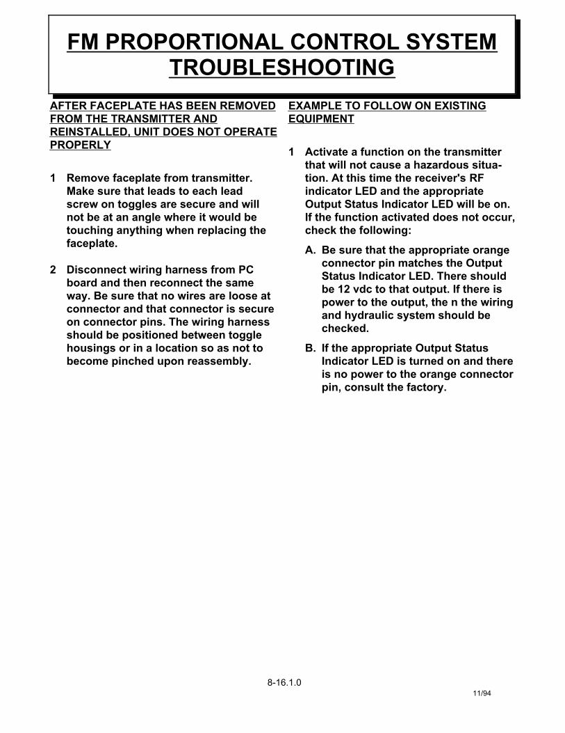
AFTER FACEPLATE HAS BEEN REMOVEDFROM THE TRANSMITTER ANDREINSTALLED, UNIT DOES NOT OPERATEPROPERLY
1 Remove faceplate from transmitter.Make sure that leads to each leadscrew on toggles are secure and willnot be at an angle where it would betouching anything when replacing thefaceplate.
2 Disconnect wiring harness from PCboard and then reconnect the sameway. Be sure that no wires are loose atconnector and that connector is secureon connector pins. The wiring harnessshould be positioned between togglehousings or in a location so as not tobecome pinched upon reassembly.
EXAMPLE TO FOLLOW ON EXISTINGEQUIPMENT
1 Activate a function on the transmitterthat will not cause a hazardous situa-tion. At this time the receiver's RFindicator LED and the appropriateOutput Status Indicator LED will be on.If the function activated does not occur,check the following:
A. Be sure that the appropriate orangeconnector pin matches the OutputStatus Indicator LED. There shouldbe 12 vdc to that output. If there ispower to the output, the n the wiringand hydraulic system should bechecked.
B. If the appropriate Output StatusIndicator LED is turned on and thereis no power to the orange connectorpin, consult the factory.
FM PROPORTIONAL CONTROL SYSTEMTROUBLESHOOTING
8-16.1.0 11/94

NOTES
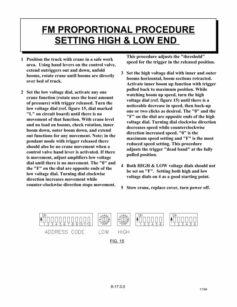
1 Position the truck with crane in a safe workarea. Using hand levers on the control valve,extend outriggers out and down, unfoldbooms, rotate crane until booms are directlyover bed of truck.
2 Set the low voltage dial, activate any onecrane function (rotate uses the least amountof pressure) with trigger released. Turn thelow voltage dial (ref. figure 15, dial marked"L" on circuit board) until there is nomovement of that function. With crane leveland no load on booms, check rotation, innerboom down, outer boom down, and extendout functions for any movement. Note; in thependant mode with trigger released thereshould also be no crane movement when acontrol valve hand lever is activated. If thereis movement, adjust amplifiers low voltagedial until there is no movement. The "0" andthe "F" on the dial are opposite ends of thelow voltage dial. Turning dial clockwisedirection increases movement whilecounter-clockwise direction stops movement.
This procedure adjusts the "threshold"speed for the trigger in the released position.
3 Set the high voltage dial with inner and outerbooms horizontal, boom sections retracted.Activate inner boom up function with triggerpulled back to maximum position. Whilewatching boom up speed, turn the highvoltage dial (ref. figure 15) until there is anoticeable decrease in speed, then back-upone or two clicks as desired. The "0" and the"F" on the dial are opposite ends of the highvoltage dial. Turning dial clockwise directiondecreases speed while counterclockwisedirection increased speed. "0" is themaximum speed setting and "F" is the mostreduced speed setting. This procedureadjusts the trigger "dead band" at the fully pulled position.
4 Both HIGH & LOW voltage dials should notbe set on "F". Setting both high and lowvoltage dials on 4 as a good starting point.
5 Stow crane, replace cover, turn power off.
FM PROPORTIONAL PROCEDURESETTING HIGH & LOW END
11/948-17.0.0
FIG. 15
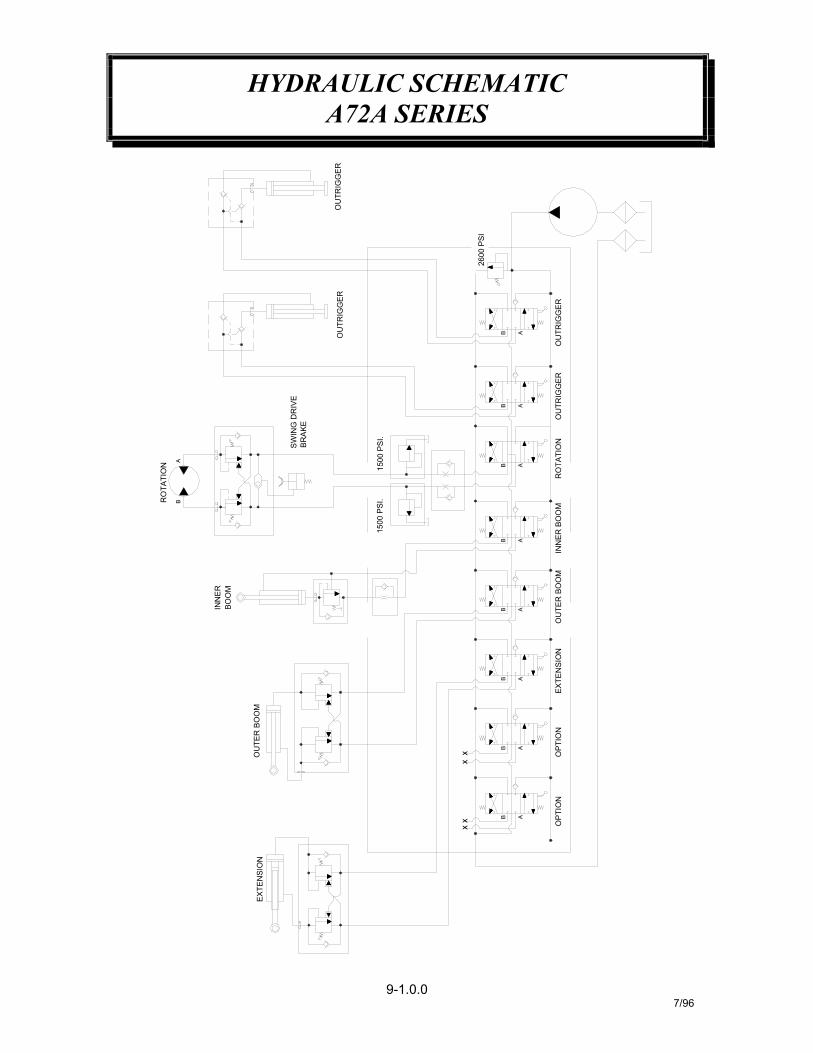
HYDRAULIC SCHEMATICA72A SERIES
9-1.0.07/96
OU
TRIG
GER
ABR
OTA
TIO
N
SW
ING
DR
IVE
BR
AK
E
OU
TRIG
GER
xx
x B A
OP
TIO
NO
PTI
ON
x
2600
PSI
B A
B A
OU
TRIG
GE
RR
OTA
TIO
NO
UTR
IGG
ER
B A
B A
B A
B A
OU
TER
BO
OM
EXTE
NSI
ON
INN
ER
BO
OM
1500
PS
I.
BOO
MIN
NE
R
1500
PSI
.
EX
TEN
SIO
NO
UTE
R B
OO
M
B A
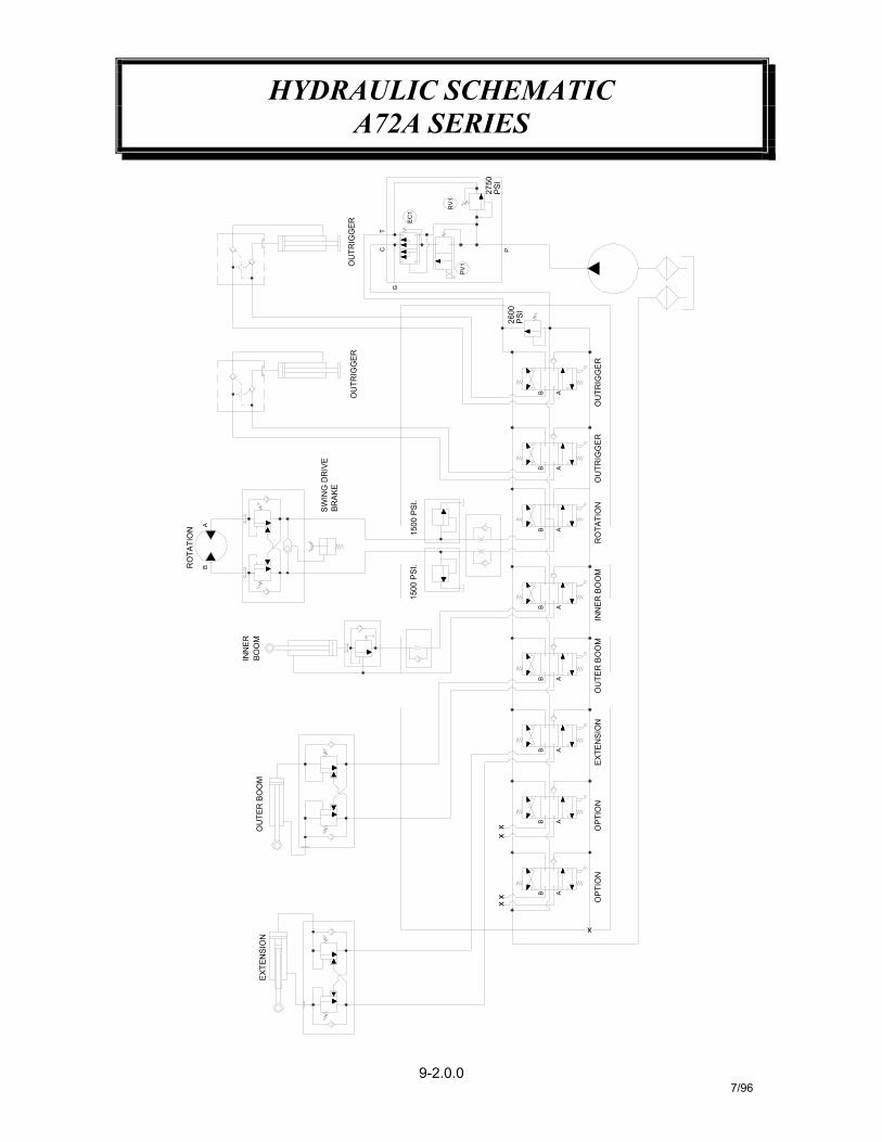
HYDRAULIC SCHEMATICA72A SERIES
9-2.0.07/96
OU
TRIG
GER
OU
TRIG
GER
AB
PSI
2600
OU
TRIG
GER
P
2750
PSI
PV
1
RV
1
G
CT
EC
1
OU
TRIG
GER
EXT
ENSI
ON
OU
TER
BO
OM
xx B A
xx
AB
INN
ERB
OO
M
RO
TATI
ON
BA
SW
ING
DR
IVE
BRA
KE
1500
PS
I.
ABB A
B A
1500
PS
I.
B A
B A
EXT
ENSI
ON
x
OP
TIO
NO
PTIO
NIN
NER
BO
OM
OU
TER
BO
OM
RO
TATI
ON
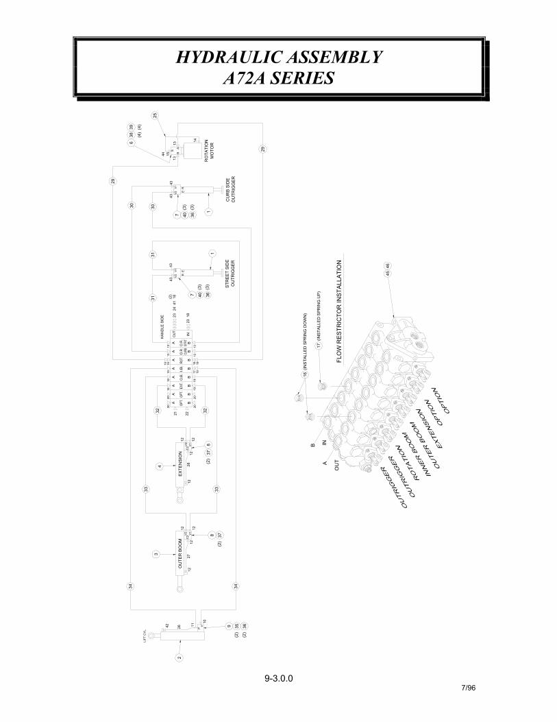
HYDRAULIC ASSEMBLYA72A SERIES
9-3.0.07/96
2
11
PV2642
10
9 36(2
)
35(2
)
29
FLO
W R
ESTR
ICTO
R IN
STA
LLA
TIO
N
HAN
DLE
SID
E
17
4
EX
TEN
SIO
N
33
OU
TER
BO
OM
12
1227
12
C2
12V1V2
34
3
12
8
33
34
37(2
)
BA
32
28
12 12
C2
12V1V
2
(2)
378
20
2221
20
1920
19
BB
B
19171916
1313
BB
B
AA
A19
2019
AA
A
1919
1613
13
BIN
A
32
16
B
OU
T
INA
CU
RB
SID
EO
UTR
IGG
ER
E
V2
(3)
361
1
(3)
1823
7 40
23(2
)41
241831
ER
4343
V1V2
(3)
3640(3
)
43
7
313030
OU
TRIG
GE
RS
TRE
ET
SID
E
MO
TOR
RO
TATI
ON
R
43V1
14
13B
13A
S
44 15
(4)
25
(4)
639
38
29
4546
(IN
STA
LLE
D S
PR
ING
DO
WN
)
(IN
STA
LLED
SPR
ING
UP
)
LIFT
CYL
.

HYDRAULIC ASSEMBLYA72A SERIES
9-3.1.07/96
HOSE ASSEMBLY (SWING DRIVE)
CONTROL VALVE (MANUAL)CONTROL VALVE (PROPORTIONAL)
ADAPTER, STR. -8 OR(M) / -6 JIC(M)ADAPTER, STR. LONG -6 O-RING / -6 JICELL, 90° -6 swivel / -6 JIC
SCREW, HX HD 1/4-NC X 1 3/4ELL, 90° -12 JIC FEM SWIVEL / -12 JIC
SCREW, SOC HD 5/16-NC X 2 1/4WASHER, SP LK 5/16
WASHER, SP LK 1/4SCREW, SOC HD 3/8-NC X 2 3/4
HOSE ASSEMBLY, (OUTER BOOM)HOSE ASSEMBLY, (LIFT CYLINDER)SCREW, HX HD 1/4-NC X 1 1/2
HOSE ASSEMBLY, (OUTRIGGER STREET SIDE)HOSE ASSEMBLY, (EXTENSION)
HOSE ASSEMBLY, (ROTATION)HOSE ASSEMBLY, (OUTRIGGER CURB SIDE)
TUBE ASSEMBLY (LIFT CYLINDER)TUBE ASSEMBLY (OUTER BOOM)TUBE ASSEMBLY (EXTENSION CYLINDER)
4546
4344
11
41
367302372010480194373047
34
4241
3940
363738
35
3233
3031
29282726
2 812210-061
11
46
367283202756
020601005810
844
2020200367164367163
005804
812309-225812206-108812206-145812210-072
812303-15222
22
2111
372262373050373049
PLUG, -12 OR(M)ADAPTER, STR. -12 OR(M) / -12 JIC(M)
SWIVEL, -10 O-RING / -8 JICPLUG, -10 OR(M)PLUG, -14 OR(M)
FLOW RESTRICTOR .120
ADAPTER, STR. -4 OR(M) / -6 JIC(M)FLOW RESTRICTOR .047
ADAPTER, STR. -10 OR(M) / -6 JIC(M)ELL, 90° -4 OR(M) / -6 JIC(M)
ADAPTER, STR. -6 OR(M) / -6 JIC(M)TEE, -6 OR(M) / -6 JIC RUNADAPTER, STR. -8 OR(M) / -8 JIC(M)
COUNTERBALANCE VALVE (O.B. AND EXT.)COUNTERBALANCE VALVE (LIFT CYLINDER)
COUNTERBALANCE VALVE (ROTATION)LOCKING VALVE (OUTRIGGER)
OUTER BOOM CYLINDER2-STAGE EXTENSION CYLINDER
OUTRIGGER CYLINDER
TEE, -12 FEM. SWIVEL NUT / -12 JIC
36712128
17
21
232425
22
1920
18
1516
1314
1211109
3672261
3672041
2
11
1750420
373048750472
750478
84
3372195330072
750419 CAP, -12 JIC
21
61
372039367144367140202755
81
11
200877367145
367122200876
4
67
5
321
ITEM
3730381
12
-367124372066
-
112
373032373034
373042
-
LIFT CYLINDER
PART NO.QTY. DESCRIPTION
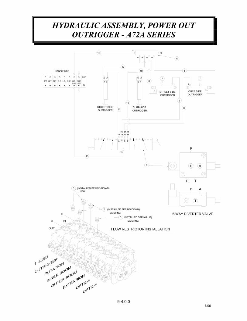
HYDRAULIC ASSEMBLY, POWER OUTOUTRIGGER - A72A SERIES
9-4.0.07/96
HANDLE SIDE
INA
OUT
B
B
A
B B B B
A A A A
FLOW RESTRICTOR INSTALLATION
(INSTALLED SPRING DOWN)
(INSTALLED SPRING DOWN)
2
3NEW
EXISTING
EXISTING
3
13
19
5
E
2014
A T B
21 181719 19
B
5-WAY DIVERTER VALVE
E
E
T
A
T
B
P
A
8
STREET SIDE
V1
OUTRIGGER
4
BB B IN
4
AA A
R E
V2
10
11CURB SIDEOUTRIGGER
10
E R
V2 V1
10
12
16 16
14
16
CURB SIDEOUTRIGGER
1 STREET SIDEOUTRIGGER
8
9
7
1 1
8
1
7
16
15
6
(INSTALLED SPRING UP)

HYDRAULIC ASSEMBLY, POWER OUTOUTRIGGER - A72A SERIES
9-4.1.07/96
ELL, 90° -8 OR(M) / -6 JIC(M)ELL, 90° -6 SWIVEL / -6 JICELL, 45° -6 SWIVEL / -6 JIC
ELL, 90° -8 OR(M) / -6 NPT(FEMALE)ADAPTER, STR. -6 NPT / -6 JIC
PLUG, -8ELL, 90° -6 OR(M) / -6 JIC(M)
HOSE ASSEMBLYADAPTER, STR. -8 OR(M) / -6 JIC(M)
HOSE ASSEMBLYHOSE ASSEMBLYHOSE ASSEMBLY
HOSE ASSEMBLYHOSE ASSEMBLY
HEADER, MANIFOLDCYLINDER, POWER OUT OUTRIGGER
FLOW RESTRICTOR, .120
5-WAY DIVERTER VALVEPLUG, -10 O-RING
ADAPTER, STR. -6 OR(M) / -6 JIC(M)FLOW RESTRICTOR. .047
5 1 372311
192021
18171615
3 330272
3306474801941
1
360042367220241175367162
1141
10
12
1413
11
9876
3 812206-108
202756812203-056
812206-118812203-0401
21
1
812203-050480206373040372305
1321
QTY.
34
21
ITEM
367226330072
372039200876
22
24
PART NO. DESCRIPTION
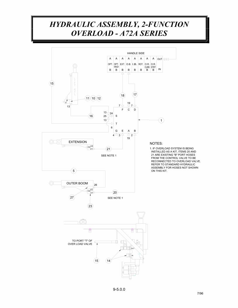
HYDRAULIC ASSEMBLY, 2-FUNCTIONOVERLOAD - A72A SERIES
9-5.0.07/96
11
C2
C2
TO PORT "T" OFOVER LOAD VALVE
EXTENSION
27
OUTER BOOM
5
VP
13
15
ASSEMBLY FOR HOSES NOT SHOWN REFER TO STANDARD HYDRAULIC RECONNECTED TO OVERLOAD VALVE. FROM THE CONTROL VALVE TO BE 21 ARE EXISTING "B" PORT HOSES INSTALLED AS A KIT, ITEMS 20 AND1. IF OVERLOAD SYSTEM IS BEING
15 14
OUT
IN
SEE NOTE 1
23
V2V1
26
20
SEE NOTE 1
V2V1 21
NOTES:
ON THIS KIT.
B
17
D
B
19
6
24
1316
1325
EG
4 3
T
A
192
F
S
7C
7
1210
B
18
BB B
1
INBB B
HANDLE SIDE
AA AA A AA A
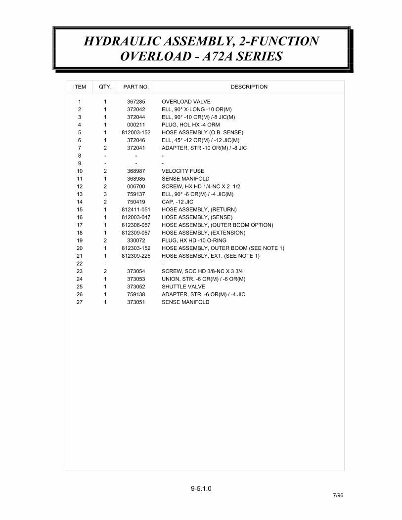
HYDRAULIC ASSEMBLY, 2-FUNCTIONOVERLOAD - A72A SERIES
9-5.1.07/96
26 1 759138 ADAPTER, STR. -6 OR(M) / -4 JICSENSE MANIFOLD37305127 1
ITEM
12 2 006700 SCREW, HX HD 1/4-NC X 2 1/2
SHUTTLE VALVE
HOSE ASSEMBLY, (SENSE)
SCREW, SOC HD 3/8-NC X 3 3/4
PLUG, HX HD -10 O-RINGHOSE ASSEMBLY, OUTER BOOM (SEE NOTE 1)HOSE ASSEMBLY, EXT. (SEE NOTE 1)
HOSE ASSEMBLY, (OUTER BOOM OPTION)HOSE ASSEMBLY, (EXTENSION)
UNION, STR. -6 OR(M) / -6 OR(M)
HOSE ASSEMBLY, (RETURN)
ELL, 90° -6 OR(M) / -4 JIC(M)
19 2 330072
373052
373054373053
812309-225812303-152
23 2
12524 1
21 122 -
20 1
- -
812003-047
812309-057812306-057
750419812411-051
759137
116
11817 1
21415 1
13 3CAP, -12 JIC
ADAPTER, STR -10 OR(M) / -8 JIC
VELOCITY FUSESENSE MANIFOLD
ELL, 45° -12 OR(M) / -12 JIC(M)
ELL, 90° -10 OR(M) /-8 JIC(M)
HOSE ASSEMBLY (O.B. SENSE)
ELL, 90° X-LONG -10 OR(M)
PLUG, HOL HX -4 ORM
OVERLOAD VALVE
5 1 812003-152
372041
368985368987
372046
9 - -
11 110 2
278 -
6 1
---
372044000211
372042367285
PART NO.
2 1
4 13 1
QTY.
1 1
DESCRIPTION
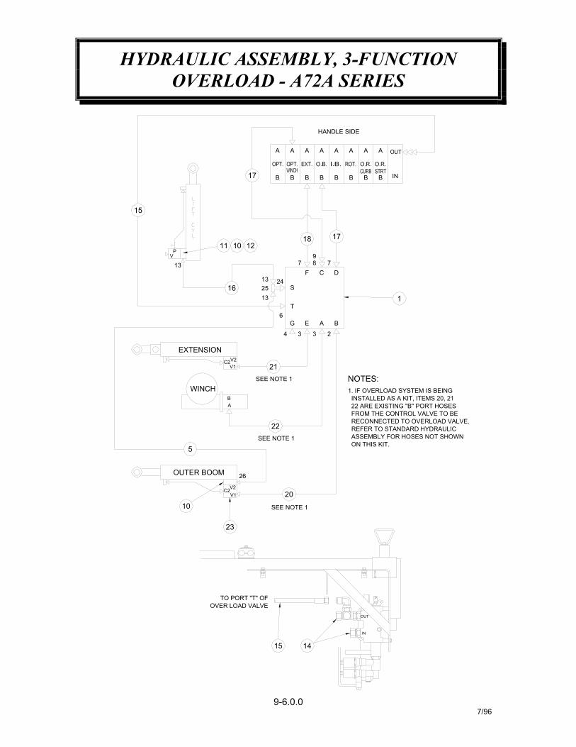
HYDRAULIC ASSEMBLY, 3-FUNCTIONOVERLOAD - A72A SERIES
9-6.0.07/96
ASSEMBLY FOR HOSES NOT SHOWN REFER TO STANDARD HYDRAULIC
ON THIS KIT.
BA
WINCHSEE NOTE 1
EXTENSIONV2C2V1 21
4
G
13V
P
1613
T6
2513 24
S
1011 12
15
17 B B
A A
22 ARE EXISTING "B" PORT HOSES INSTALLED AS A KIT, ITEMS 20, 21
FROM THE CONTROL VALVE TO BE
1. IF OVERLOAD SYSTEM IS BEING
NOTES:
3 3
E A
2
B
F C D
1
97 8 7
18 17
B B B B B B IN
HANDLE SIDE
A A A A A A
RECONNECTED TO OVERLOAD VALVE.
SEE NOTE 1
15
23
OVER LOAD VALVETO PORT "T" OF
OUTER BOOM
10
V2V1
C2
26
20
5SEE NOTE 1
22
14
IN
OUT

HYDRAULIC ASSEMBLY, 3-FUNCTIONOVERLOAD - A72A SERIES
9-6.1.07/96
1
11
- - -812309-057812306-057812003-047812411-051
1211
10
12
1413
11
9876
2 368987
750419759137
3689850067002
23
1
367145330274372041372046
1121
QTY.
34
21
ITEM
372044000211
372042367285
21
11
PART NO. DESCRIPTION
ADAPTER, STR. -6 OR(M) / -4 JICSENSE MANIFOLD
UNION, STR. -6 OR(M) / -6 OR(M)SHUTTLE VALVE
2627
2524
373051759138373052373053
11
11
HOSE ASSEMBLY, (WINCH)SCREW, SOC HD 3/8-NC X 3 3/4
HOSE ASSEMBLY, OUTER BOOM (SEE NOTE 1)HOSE ASSEMBLY, EXT. (SEE NOTE 1)
HOSE ASSEMBLY, (OUTER BOOM OPTION)HOSE ASSEMBLY, (EXTENSION)
HOSE ASSEMBLY, (RETURN)HOSE ASSEMBLY, (SENSE)
ELL, 90° -6 OR(M) / -4 JIC(M)CAP, -12 JIC
VELOCITY FUSESENSE MANIFOLDSCREW, HX HD 1/4-NC X 2 1/2
ADAPTER, STR. 10 OR(M) / -8 OR(F)ADAPTR, STR. -8 OR(M) / -8 JIC(M)
ELL, 45° -12 OR(M) / -12 JIC(M)ADAPTER, STR -10 OR(M) / -8 JIC
ELL, 90° -10 OR(M) /-8 JIC(M)
HOSE ASSEMBLY (O.B. SENSE)PLUG, HOL HX -4 ORM
OVERLOAD VALVEELL, 90° X-LONG -10 OR(M)
5 1 812003-152
19
2322
2021
18171615
373054812309-285812309-225812303-152
2
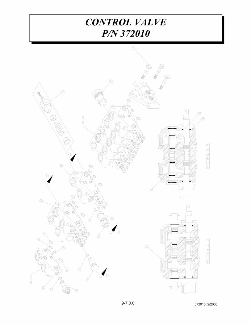
CONTROL VALVEP/N 372010
9-7.0.0 372010 2/2000
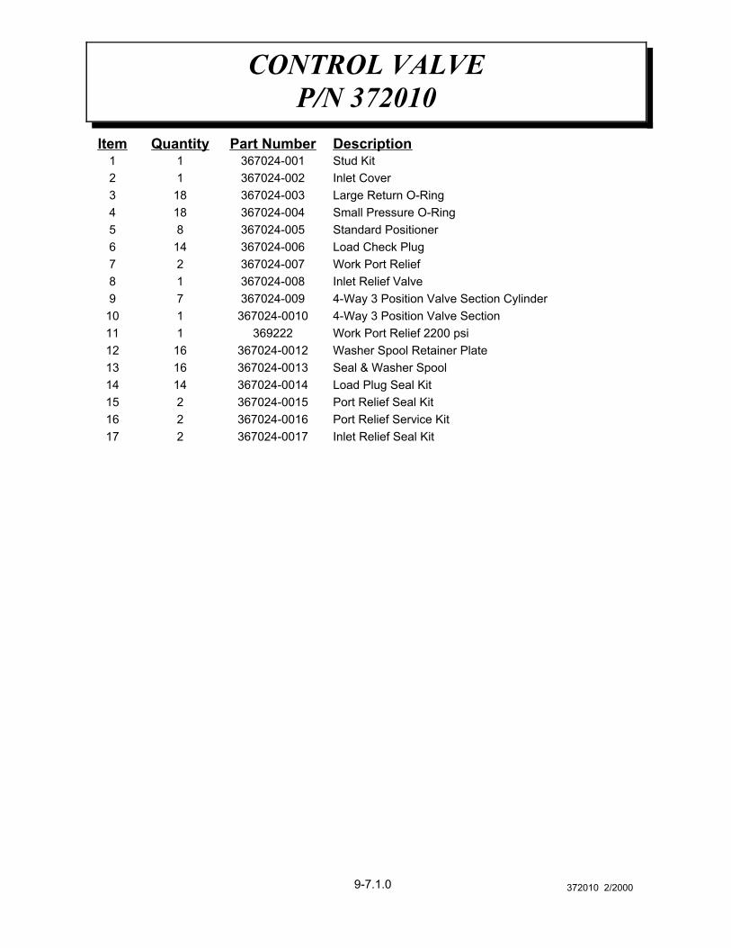
CONTROL VALVEP/N 372010
9-7.1.0 372010 2/2000
Inlet Relief Seal Kit367024-0017217Port Relief Service Kit367024-0016216Port Relief Seal Kit367024-0015215Load Plug Seal Kit367024-00141414Seal & Washer Spool367024-00131613Washer Spool Retainer Plate367024-00121612Work Port Relief 2200 psi3692221114-Way 3 Position Valve Section367024-00101104-Way 3 Position Valve Section Cylinder367024-00979Inlet Relief Valve367024-00818Work Port Relief367024-00727Load Check Plug367024-006146Standard Positioner367024-00585Small Pressure O-Ring367024-004184Large Return O-Ring367024-003183Inlet Cover367024-00212Stud Kit367024-00111DescriptionPart NumberQuantityItem
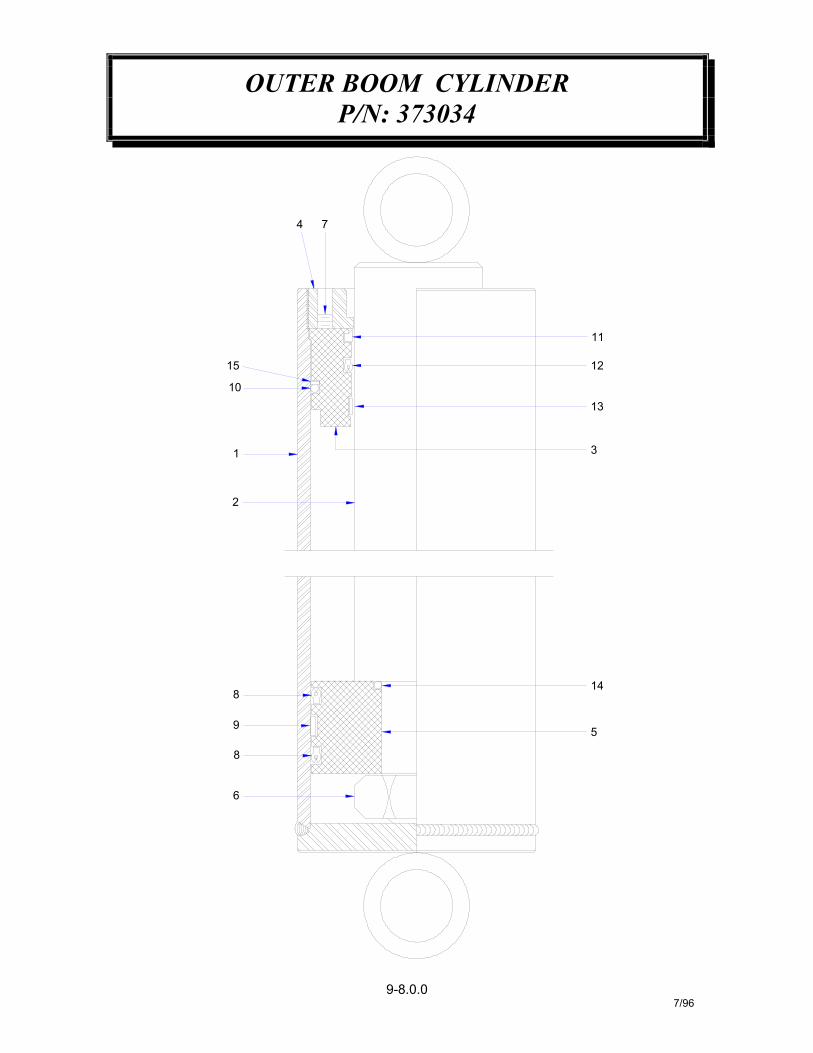
OUTER BOOM CYLINDERP/N: 373034
9-8.0.07/96
8
6
9
8
5
2
1
10
15
4 7
14
3
13
12
11
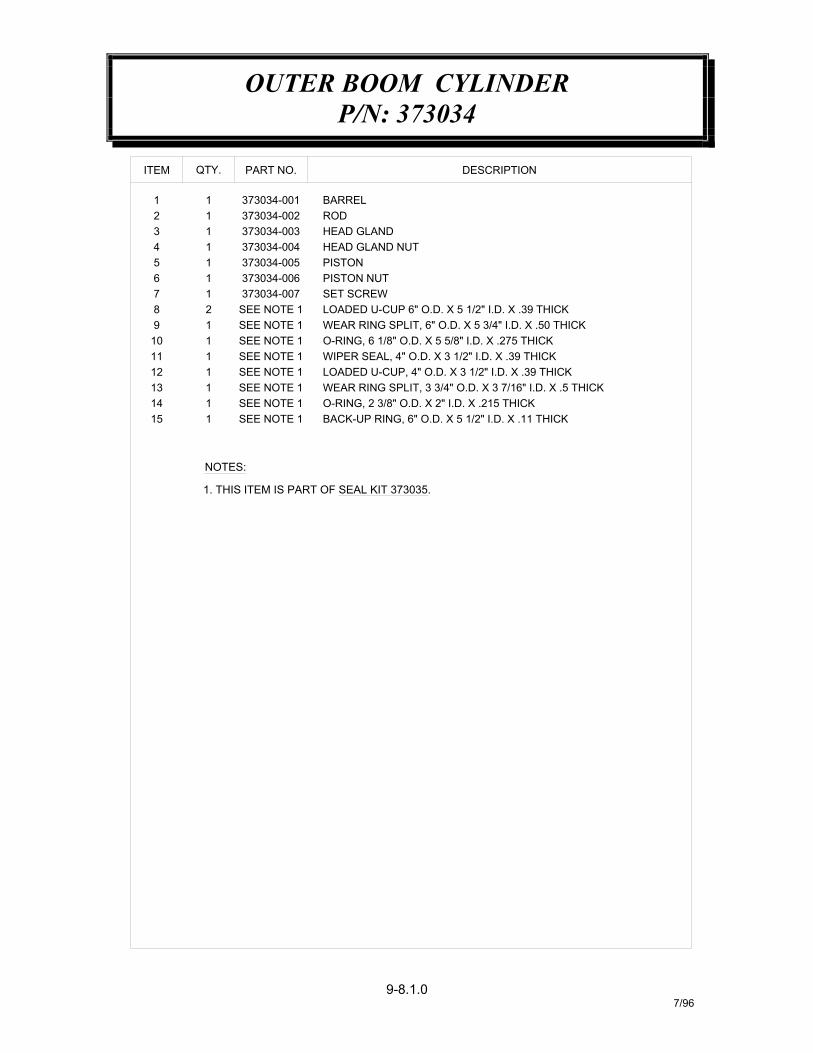
OUTER BOOM CYLINDERP/N: 373034
9-8.1.07/96
DESCRIPTIONPART NO.
BARRELROD
373034-003373034-004
373034-002373034-001
QTY.ITEM
11
12
143 1
SEE NOTE 1SEE NOTE 1
373034-006373034-007
SEE NOTE 1
SEE NOTE 1SEE NOTE 1
SEE NOTE 1SEE NOTE 1
11
67
21
89
111
11
1314
12 1
10 1
SEE NOTE 1115
NOTES:
5 1 373034-005 PISTON
O-RING, 2 3/8" O.D. X 2" I.D. X .215 THICK
WIPER SEAL, 4" O.D. X 3 1/2" I.D. X .39 THICKLOADED U-CUP, 4" O.D. X 3 1/2" I.D. X .39 THICKWEAR RING SPLIT, 3 3/4" O.D. X 3 7/16" I.D. X .5 THICK
WEAR RING SPLIT, 6" O.D. X 5 3/4" I.D. X .50 THICKO-RING, 6 1/8" O.D. X 5 5/8" I.D. X .275 THICK
PISTON NUT
LOADED U-CUP 6" O.D. X 5 1/2" I.D. X .39 THICK
HEAD GLANDHEAD GLAND NUT
1. THIS ITEM IS PART OF SEAL KIT 373035.
SET SCREW
BACK-UP RING, 6" O.D. X 5 1/2" I.D. X .11 THICK
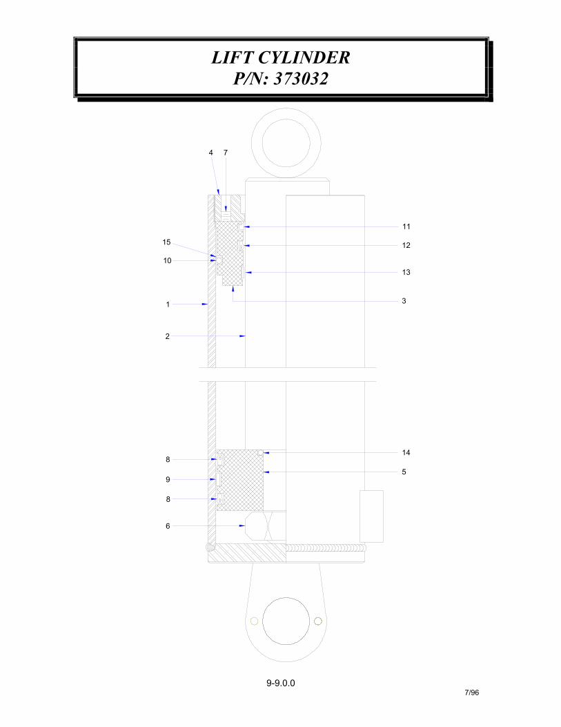
LIFT CYLINDERP/N: 373032
9-9.0.07/96
4 7
3
13
12
11
6
8
9
85
14
2
1
15
10
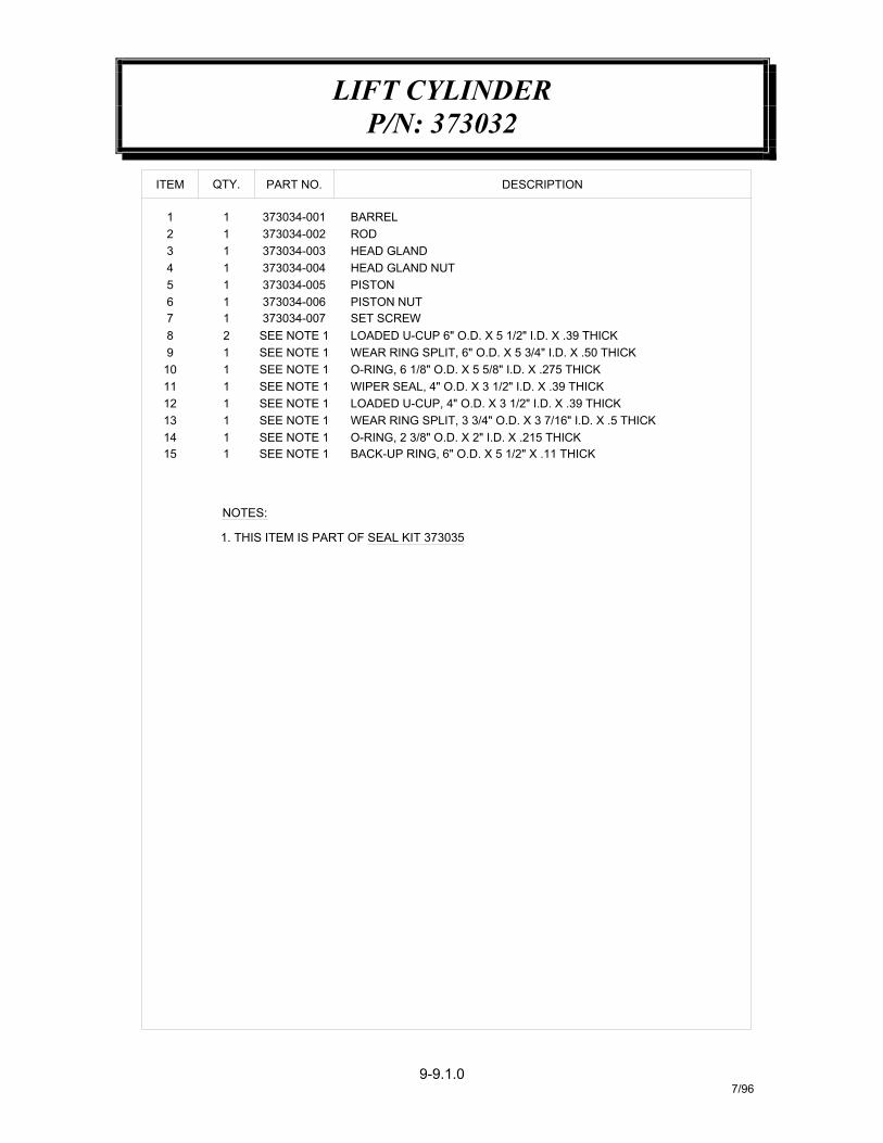
LIFT CYLINDERP/N: 373032
9-9.1.07/96
O-RING, 2 3/8" O.D. X 2" I.D. X .215 THICK
WIPER SEAL, 4" O.D. X 3 1/2" I.D. X .39 THICKLOADED U-CUP, 4" O.D. X 3 1/2" I.D. X .39 THICKWEAR RING SPLIT, 3 3/4" O.D. X 3 7/16" I.D. X .5 THICK
WEAR RING SPLIT, 6" O.D. X 5 3/4" I.D. X .50 THICKO-RING, 6 1/8" O.D. X 5 5/8" I.D. X .275 THICK
PISTON NUT
LOADED U-CUP 6" O.D. X 5 1/2" I.D. X .39 THICK
HEAD GLANDHEAD GLAND NUT
1. THIS ITEM IS PART OF SEAL KIT 373035
SET SCREW
BACK-UP RING, 6" O.D. X 5 1/2" X .11 THICK
5 1 373034-005 PISTON
NOTES:
15 1 SEE NOTE 1
10 1
12 1
1413
11
11 1
98
12
76
11
SEE NOTE 1
SEE NOTE 1
SEE NOTE 1SEE NOTE 1
SEE NOTE 1
SEE NOTE 1SEE NOTE 1
373034-006373034-007
QTY.
3 14 1
21
11
ITEM
373034-003373034-004
373034-002373034-001 BARREL
ROD
PART NO. DESCRIPTION
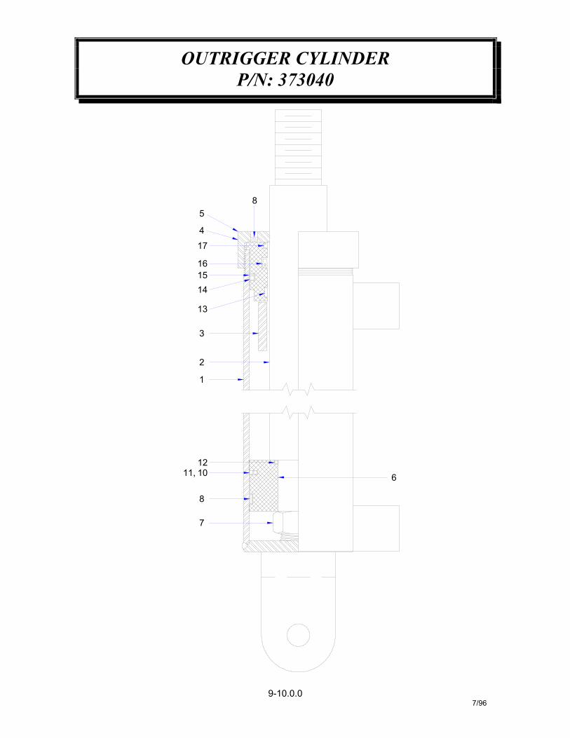
OUTRIGGER CYLINDERP/N: 373040
9-10.0.07/96
8
7
2
8
121011,
1
3
14
13
1516
17
4
5
6
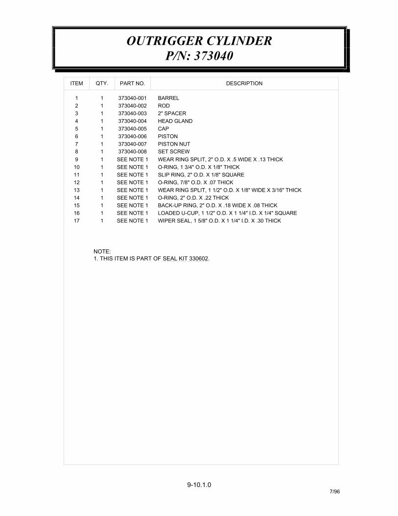
OUTRIGGER CYLINDERP/N: 373040
9-10.1.07/96
LOADED U-CUP, 1 1/2" O.D. X 1 1/4" I.D. X 1/4" SQUAREWIPER SEAL, 1 5/8" O.D. X 1 1/4" I.D. X .30 THICK
O-RING, 2" O.D. X .22 THICKBACK-UP RING, 2" O.D. X .18 WIDE X .08 THICK
SLIP RING, 2" O.D. X 1/8" SQUAREO-RING, 7/8" O.D. X .07 THICKWEAR RING SPLIT, 1 1/2" O.D. X 1/8" WIDE X 3/16" THICK
WEAR RING SPLIT, 2" O.D. X .5 WIDE X .13 THICKO-RING, 1 3/4" O.D. X 1/8" THICK
PISTON NUT
2" SPACERHEAD GLAND
1. THIS ITEM IS PART OF SEAL KIT 330602.
SET SCREW
5 1 373040-005 CAP
NOTE:
17 11615
11
SEE NOTE 1SEE NOTE 1SEE NOTE 1
10 1
12 1
1413
11
11 1
98
11
76
11
SEE NOTE 1
SEE NOTE 1
SEE NOTE 1SEE NOTE 1
SEE NOTE 1
SEE NOTE 1
373040-007373040-006
373040-008
PISTON
3 14 1
21
11
ITEM QTY.
373040-003373040-004
373040-002373040-001 BARREL
ROD
PART NO. DESCRIPTION
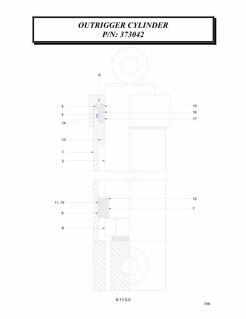
OUTRIGGER CYLINDERP/N: 373042
9-11.0.07/96
8
9
11, 10
7
12
2
1
13
14
4
5
6
16
17
15
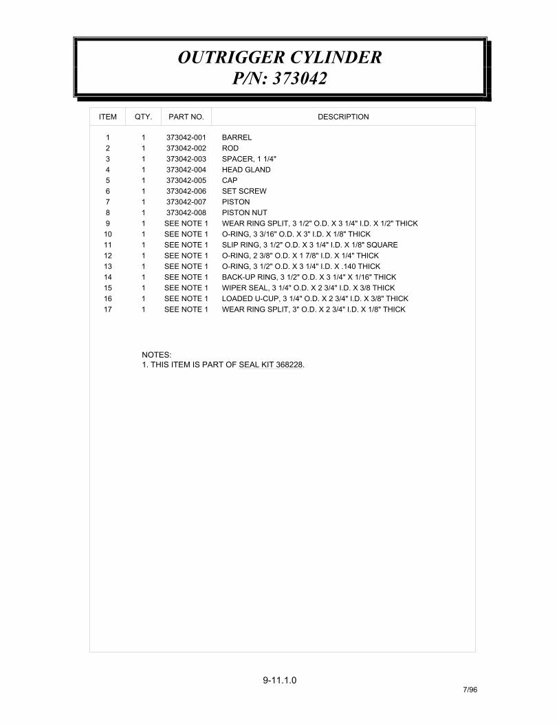
OUTRIGGER CYLINDERP/N: 373042
9-11.1.07/96
WEAR RING SPLIT, 3" O.D. X 2 3/4" I.D. X 1/8" THICK
WIPER SEAL, 3 1/4" O.D. X 2 3/4" I.D. X 3/8 THICKLOADED U-CUP, 3 1/4" O.D. X 2 3/4" I.D. X 3/8" THICK
O-RING, 3 1/2" O.D. X 3 1/4" I.D. X .140 THICKBACK-UP RING, 3 1/2" O.D. X 3 1/4" X 1/16" THICK
O-RING, 3 3/16" O.D. X 3" I.D. X 1/8" THICKSLIP RING, 3 1/2" O.D. X 3 1/4" I.D. X 1/8" SQUAREO-RING, 2 3/8" O.D. X 1 7/8" I.D. X 1/4" THICK
PISTON NUTWEAR RING SPLIT, 3 1/2" O.D. X 3 1/4" I.D. X 1/2" THICK
SET SCREW
SPACER, 1 1/4"HEAD GLAND
1. THIS ITEM IS PART OF SEAL KIT 368228.
5 1 373042-005 CAP
NOTES:
17 11615
11
SEE NOTE 1SEE NOTE 1SEE NOTE 1
10 1
12 1
1413
11
11 1
98
11
76
11
SEE NOTE 1
SEE NOTE 1
SEE NOTE 1SEE NOTE 1
SEE NOTE 1
373042-008373042-007373042-006
SEE NOTE 1
PISTON
3 14 1
21
11
ITEM QTY.
373042-003373042-004
373042-002373042-001 BARREL
ROD
PART NO. DESCRIPTION
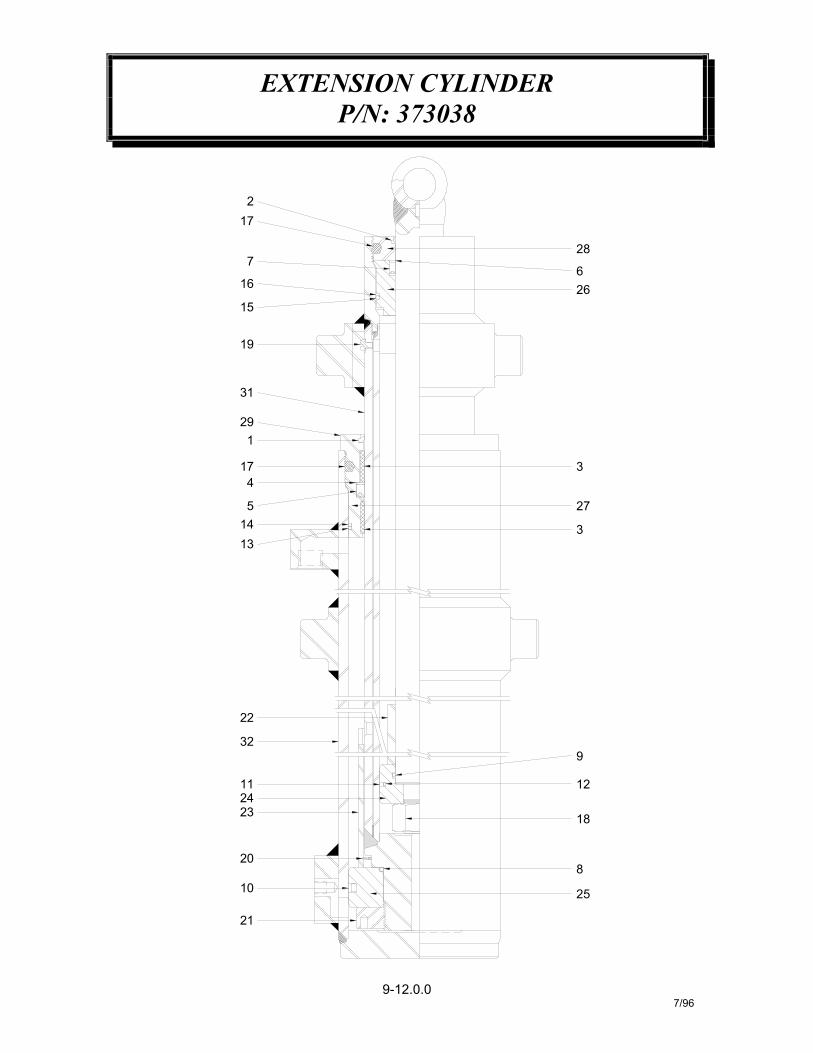
EXTENSION CYLINDERP/N: 373038
9-12.0.07/96
23
21
10
20
2411
22
32
1
13145
174
29
31
19
8
25
18
12
9
3
27
3
16
15
7
172
28
266
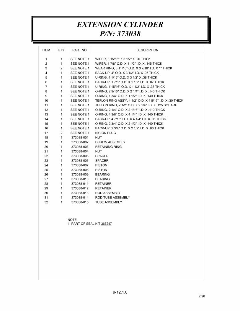
EXTENSION CYLINDERP/N: 373038
9-12.1.07/96
ROD TUBE ASSEMBLYTUBE ASSEMBLY
30
3231
2829
2726
1. PART OF SEAL KIT 367247NOTE:
373038-012
373038-010373038-011
373038-009
373038-015373038-014373038-0131
11
1111
ROD ASSEMBLYRETAINER
BEARINGBEARINGRETAINER
BACK-UP, 1 7/8" O.D. X 1 1/2" I.D. X .07 THICKU-RING, 1 15/16" O.D. X 1 1/2" I.D. X .38 THICK
WEAR RING, 3 11/16" O.D. X 3 7/16" I.D. X 1" THICK
U-RING, 4 1/16" O.D. X 3 1/2" X .38 THICKBACK-UP, 4" O.D. X 3 1/2" I.D. X .07 THICK
WIPER, 3 15/16" X 3 1/2" X .20 THICKWIPER, 1 7/8" O.D. X 1 1/2" I.D. X .145 THICK
SCREW ASSEMBLY
O-RING, 2 3/4" O.D. X 2 1/2" I.D. X .140 THICKBACK-UP, 2 3/4" O.D. X 2 1/2" I.D. X .06 THICK
O-RING, 4 3/8" O.D. X 4 1/4" I.D. X .140 THICKBACK-UP, 4 7/16" O.D. X 4 1/4" I.D. X .06 THICK
TEFLON RING ASS'Y, 4 1/2" O.D. X 4 5/16" I.D. X .30 THICKTEFLON RING, 2 1/2" O.D. X 2 1/4" I.D. X .125 SQUAREO-RING, 2 1/4" O.D. X 2 1/16" I.D. X .110 THICK
O-RING, 1 3/4" O.D. X 1 1/2" I.D. X .140 THICKO-RING, 2 9/16" O.D. X 2 1/4" I.D. X .140 THICK
17
2524
2223
192021
18
13
1516
14
1112
910
SEE NOTE 1 NYLON PLUG2
373038-005373038-004
373038-002373038-003
373038-001
373038-008373038-007373038-006
1111
111
1
SPACER
PISTONPISTON
SPACER
RETAINING RINGNUT
NUT
SEE NOTE 1SEE NOTE 1SEE NOTE 1
SEE NOTE 1SEE NOTE 1
SEE NOTE 1SEE NOTE 1
SEE NOTE 1
1
11
1
1111
4
8765
23
1
ITEM
SEE NOTE 1
SEE NOTE 1SEE NOTE 1SEE NOTE 1SEE NOTE 1
SEE NOTE 1SEE NOTE 1
SEE NOTE 1
1
1111
12
1
QTY. PART NO. DESCRIPTION
1 REMOVE CYLINDER FROM CRANE
A. disconnect shaft end of cylinderfrom the crane.
B. retract cylinder rod with oil fromhydraulic system until about 12"-14"of rod is extended. The barrel mustbe filled with oil to prevent acompressed air chamber beingformed which could result in injury attime of disassembly.
C. remove cylinder from crane andplace on supports.
D. place an oil pan under the cylinderhead gland and return port.
2 REMOVE RETURN TUBE FROMCYLINDER
DANGER: there could be trappedpressure in the cylinder, unscrewreturn tube fitting slowly andcarefully to relieve any trappedpressure.
3 REMOVE HEAD GLAND
A. unscrew head gland nut setscrewand head gland nut from cylinder.
B. attach a porta-power hand pump or ahydraulic line from crane circuit valveto the return port on cylinder.
C. operate hand pump or crane circuitvalve to force the head gland assem-bly out of the cylinder.
WARNING! Never use compressed air toforce head gland assembly out of cylinder.
Personal injury could result as well asdamage to cylinder components.
D. use great care when removing headgland assembly from cylinder, do notpry out with a screwdriver.
E. once head gland assembly is out ofcylinder move the assembly carefullyto rod eye taking care not to damagerod assembly.
4 RELIEVE CYLINDER PRESSURE
Since it is possible to trap pressure incylinders equipped with dual counterbal-ance valves (outer boom, extension, and
outrigger up-down cylinders), do notattempt to remove counterbalance valvewithout first making sure that all trappedpressure is relieved. This can be done by
adjusting the extend counterbalancecartridge so that it's holding pressure is
zero.
A. loosen the jam nut on cartridge. Theextend cartridge is located next to thereturn tube fitting on counterbalancevalve.
B. the trapped pressure can now berelieved by turning the valve stem inuntil it is firmly seated.
Note: it is very important that a record iskept of the number of turns the valve is
turned in and upon completion of service,return the valve stem to its originalposition and tighten jam nut. This is
required for the counterbalance valve tohave the proper factory set holding
pressure.
5 REMOVE COUNTERBALANCE VALVE
A. remove counterbalance valve fromcylinder
CYLINDER SEAL REPLACEMENT
7/969-13.0.0
6 REMOVE ROD/PISTON ASSEMBLY
A. remove the rod and piston assemblyby hand. great care should be usedwhen handling rod assembly toprevent damage to the assembly.
7 DISASSEMBLE PISTON ASSEMBLY
A. remove piston nut.
B. remove piston.
C. remove head gland.
Note "loctite" is used during originalassembly to secure nut to rod. If neces-sary, heat nut to 400-500 degrees toremove nut. If heat is required for removal,replace nut and any other damaged parts.
8 CLEAN AND INSPECT PARTS
A. Clean and inspect cylinder barrel,rod assembly, head gland assembly,piston assembly, and all other cylin-der components for damage.
9 REPLACE SEALS
A. remove all old cylinder seals andreplace with new seals from seal kit.
B. it is highly recommended that allseals be replaced any time the cylin-der is disassembled.
10 ASSEMBLE PISTON/ROD ASSEMBLY
A. apply water resistant grease to innerdiameter of head gland and install onrod.
B. install piston assembly.
C. apply "loctite #271" to rod threads.
D. install piston nut; torque to 300-350ft-lbs for all 2"-12 nuts, 165 ft-lbs forall 3/4"-16 nuts.
E. use a cold chisel to pin threads in 2-3places around nut.
11 INSTALL ROD ASSEMBLY
A. apply water resistant grease to theoutside diameter of piston and innerdiameter of head gland duringinstallation.
B. apply "never seez" or equivalentbetween head gland and barrel whenassembling.
Great care should be used when installingrod assembly into barrel of cylinder toprevent nicking piston seals. Damagingthe edges of seals is likely to causepremature seal failure.
C. install head gland nut once headgland assembly is in place. Tightenhead gland nut and secure withsetscrew if required.
12 INSTALL COUNTERBALANCE VALVE
A. install counterbalance valve in itsoriginal position.
B. install return tube on cylinder.
13 INSTALL CYLINDER
A. install cylinder on the crane and pinin place
B. test cylinder by extending andretracting cylinder to its full lengthand holding in place while air ispurged.
C. check for leaks.
D. re-tighten head gland nut once cylin-der has been purged of air.
CYLINDER SEAL REPLACEMENT
7/969-13.1.0

NOTES

1 WARNING: never use compressed air toassist in removing the rod or head glandassembly. The use of compressed airmay result in propelling the assemblyout of the cylinder and may causeserious injury or death.
2 If solvent is used to clean the internalcylinder components, all traces ofsolvent must be removed.Any residualsolvent will damage seals. The use ofsolvents should be done in a well venti-lated area.
3 Once cylinder has been disassembledand thoroughly cleaned, reassemble ina clean environment, i.e. one that is freeof dust and dirt.
4 DO not clamp cylinder in a vise, it maydamage cylinder.
5 DO not clamp the machined or platedsurface of the rod assembly in vise,damage to the rod assembly will result.
6 DO replace all seals once cylinder hasbeen disassembled. This will ensureproper operation of cylinder and reducefuture downtime.
7 Use great care when installing rodassembly into cylinder. Damage to sealsmay result in premature failure of seals.
8 DO replace any worn of damaged cylin-der components.
9 It is possible to trap pressure in cylin-ders equipped with dual counterbalancevalves (outer boom, extension andoutrigger up-down). Dual counterbal-ance valves lock both the extend andretract sides of the cylinder piston. DoNOT attempt to remove counterbalancevalve without fist assuring that allpossible trapped pressure is relieved.
10 Apply "loctite #271" to rod assemblythreads, apply grease to the outsidediameter of piston and inner diameter ofhead gland. Use "never-seez" or equiva-lent between head gland and barrelwhen assembling cylinder.
IMPORTANT!SAFETY TIPS AND PRECAUTIONS FOR WORKING
WITH HYDRAULIC CYLINDERS
7/969-14.0.0
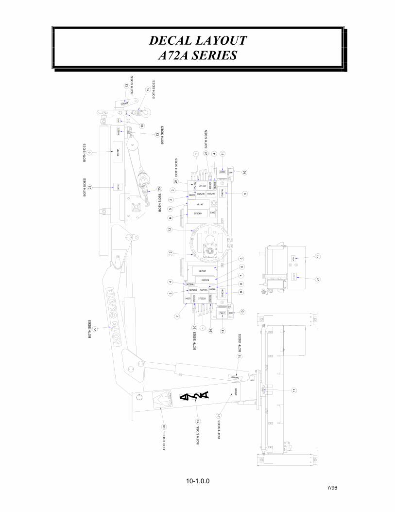
DECAL LAYOUTA72A SERIES
10-1.0.07/96
13
BO
TH S
IDES
15
523
BO
TH S
IDE
SB
OTH
SID
ES
3672
41
14
22
BOTH
SID
ES
BO
TH S
IDES
13B
OTH
SID
ES
25
BO
TH S
IDES
38
24
1 26 4
BO
TH S
IDES
367246
367239
3723
21
367250
372320
56
1212
4
367241
040529
367246
367241
040529
BO
TH S
IDE
S
1175
9016
109
56
78
3672
44 1627
3
2
3723
21
367250
26 1
367239
372320
24
BO
TH S
IDES
TULS
A, O
K. 9
18-4
38-2
760
20B
OTH
SID
ES
A219
BO
TH S
IDES
A 7
7590
16 910
BO
TH S
IDES
18
11
040519
3730
26
BO
TH S
IDES
21
17

DECAL LAYOUTA72A SERIES
10-1.1.07/96
DECAL, DANGER SCISSORS POINT18 2 040519
373025 STANDARD DECAL KIT373025-001 WINCH DECAL KIT373025-002 POWER OUT OUTRIGGER DECAL KIT
372321373028
040518372322
373027
367307368111373026368110
2627
2524
19
2322
2021
21
22
222
22
DECAL, 5-WAY VALVE FUNCTIONCAUTION, 11 GPM 2600 PSI
DECAL, WINCH FUNCTIONDECAL, DANGER STAY CLEAR
DECAL, AUTO CRANEDECAL, WINCH WARNING
DECAL, A-72ADECAL, AUTO CRANELOAD CHART
367241
367243367244040630
040581
367242
367251040517
759017
759016040580367239040529
367250367246
040579372320
PART NO.
8 2
171615
10
12
1413
11
9
4
11
24
24
22
ITEM
3
67
45
21
2
22
24
QTY.
22
DESCRIPTION
DECAL, DANGER
DECAL, GREASE
DECAL, DANGER STAY CLEARDECAL, HYD. FLUID LEVEL
DECAL, DANGER STAY CLEARDECAL, DANGER STAY CLEAR
DECAL, DANGER CRUSHINGDECAL, CAUTIONDECAL, ARROW
DECAL, DANGER OUTRIGGERS
DECAL, DANGERDECAL, STOWING
DECAL, STOWING
DECAL, DANGERDECAL, DANGER LOADLINE
DECAL, CONTROL HANDLEDECAL, CAUTION
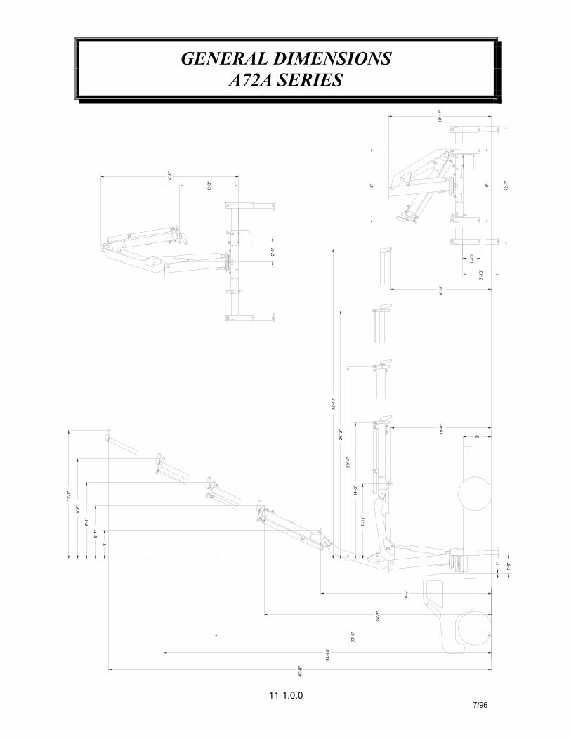
GENERAL DIMENSIONSA72A SERIES
11-1.0.07/96
40'-8"
34'-10"
29'-6"
5'-7"
3'
10'-8"
13'-7"
8'-1"
24'-2"
14'-5"
7'-11"
20'-4"
32'-10"
26'-3"
6'-3"14'-8"
2'-1"
8'
3'-10"
18'-2"
1"
1'-8"
3'
10'-8"
10'-9"
1'-10"
10'-11"
12'-7"
8'
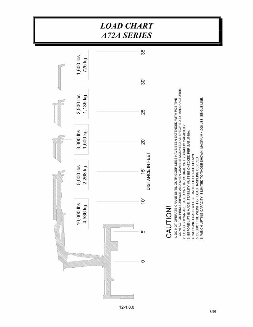
LOAD CHARTA72A SERIES
12-1.0.07/96
1,60
0 lb
s.72
5 kg
. 35'
2,50
0 lb
s.3,
300
lbs.
1,50
0 kg
.1,
135
kg.
5,00
0 lb
s.10
,000
lbs.
4,53
6 kg
.2,
268
kg.
25'
20'
15'
5'10
'
CA
UTI
ON
!
4. W
OR
KIN
G L
OAD
S W
ILL
BE
LIM
ITE
D T
O T
HO
SE S
HO
WN
.
1. D
O N
OT
OP
ER
ATE
CR
AN
E U
NTI
L O
UTR
IGG
ER
LE
GS
HA
VE B
EEN
EX
TEN
DE
D W
ITH
PO
SIT
IVE
3. B
EFO
RE
LIF
T IS
MAD
E, S
TABI
LITY
MU
ST
BE
CH
EC
KED
PE
R S
AE J
765A
.2.
LO
AD
S S
HO
WN
AR
E B
AS
ED
ON
STR
UC
TUR
AL
OR
HY
DR
AULI
C C
APAB
ILIT
Y.
DIS
TAN
CE
IN F
EE
T
5. D
ED
UC
T TH
E W
EIG
HT
OF
LOA
D H
AND
LIN
G D
EVIC
ES.
0
6. W
INC
H L
IFTI
NG
CA
PA
CIT
Y IS
LIM
ITE
D T
O T
HO
SE S
HO
WN
. MA
XIM
UM
4,0
00 L
BS.
SIN
GLE
LIN
E.
CO
NTA
CT
ON
FIR
M S
UR
FAC
E A
ND
WH
EN
CR
AN
E IS
MO
UN
TED
AS
SP
ECIF
IED
BY
MA
NU
FAC
TUR
ER
.
30'


P.O. Box 580697 * Tulsa, OK 74158-0697
4707 N. Mingo Rd. * Phone (918) 836-0463
LIMITED WARRANTY 2 YEAR PARTS AND LABOR
Auto Crane will warranty to the consumer for a period of (2) years parts and labor from the date of purchase. Each new Auto Crane unit they sell will be free under normal use and service from defects in material and workmanship. Date of purchase will be honored as the date indicated on the Bill of Sale, which must accompany the Warranty Registration and be on file with Auto Crane. Absent a valid Warranty Registration and appropriate documentation, the original date of manufacture, as indicated by the serial number on the product, will be used to determine the effective date of the 2 year warranty. The obligation of Auto Crane under this warranty is limited to the replacement or repair of parts that appear to the manufacturer after review and/or inspection to be defective and paid flat rate labor for replacing defective parts. This warranty does not obligate Auto Crane to bear the travel time charges in connection with the replacement or repair of defective parts. Responsibility for customer's claims arising from misapplication, abuse, misuse or alteration of equipment or parts lies with the distributor or user and no warranty obligation is assumed in these circumstances by Auto Crane. Auto Crane will in no event be liable for any consequential damages or contingent liabilities arising out of the failure of any Auto Crane Product or parts to operate properly. Auto Crane makes no warranty in respect to component accessories, it being subject to the warranties of their respective manufacturers. If field service, at the request of the distributor, is rendered and fault is found not to be with Auto Crane's product, the distributor shall pay the time and expense of the field representative. Claims for service labor or other expenses that have incurred by the buyer without approval or authorization or Auto Crane will not be accepted. When applying for warranty, claims may be handled by contacting your nearest authorized Auto Crane Distributor. All claims are to be filed in writing on an Auto Crane Warranty Claim Form. AUTO CRANE COMPANY IS UNDER NO OLIGATION TO EXTEND THIS WARRANTY TO ANY CUSTOMER FOR WHICH AN AUTO CRANE DELIVERY REPORT FORM HAS NOT BEEN COMPLETED AND ON FILE WITH AUTO CRANE COMPANY
Limited Warranty 2 Years Effective September 2, 2003