Embed Size (px)
Citation preview
A.7.5 8th International Conference on Insulated Power Cables A.7.5
Jicable’11 – 19 – 23 June 2011, Versailles - France
DEVELOPMENT AND QUALIFICATION OF DEEPEST WATER POWER UMBILICAL
Arild FIGENSCHOU, Jan Ole DUNSERUD, Aker Solutions, (Norway), [email protected], [email protected] Daniel ISUS, Grupo General Cable Sistemas S.A., (Spain), [email protected] Emmanuel BIC, Silec Cable, (France), [email protected]
ABSTRACT
This paper describes the world’s first umbilical system to deliver substantial power at 2700m water depth. The system is developed to deliver power to subsea pumps through a dynamic power cable hanging from a moored turret buoy in a catenary installation down to the seabed.
Attention is focused on the development, design and qualification of the umbilical and its main components, the power cables, performed in close cooperation between the different companies involved.
KEYWORDS
Power umbilical, dynamic, submarine, deep water, boosting, pumps
INTRODUCTION
As the oil and gas industry looks for ways to keep pace with the growing worldwide demand for oil, subsea developments are moving into ever increasing water depths and operators are looking towards subsea boosting technology as a means of getting the most out of their reservoirs. The power distribution umbilicals, which are needed to supply electrical power to the subsea boosting pumps, will be challenged by more extreme tension loads due to the deeper waters.
This paper presents a technical description of a power umbilical to be installed in the area of the central Gulf of Mexico at 2700m water depth; the first of its kind to transmit power over this depth sufficient to power subsea boosting pumps. The requirements of the power umbilical system required a transmission of 1.7MVA including two three-phase supplies and a spare three-phase circuit; therefore, a total of nine cables, rated 12/20 kV with a conductor cross-sectional area of 150mm2 each. In addition, due to the long length of the umbilical cable, including dynamic (that part of the umbilical suspended in water) and static (that part of the umbilical laying on the seabed) sections, 2 sets of splices were included in static section.
Attention is focused on the development and design principles of the umbilical and its main components, presenting the challenges encountered, which to date are unique. Also, a thorough qualification program is described that has verified the umbilical’s ability to survive the rigours of installation and operational life at the most extreme conditions.
ULTRA DEEPWATER CHALLENGES
The traditional way to limit the strain in umbilicals is to increase the axial stiffness by adding steel armouring. But for very deep water applications, steel as armouring
material does not work efficiently to reduce the strain of an umbilical. If a structural member suspended from a top point is hanging vertically and exposed to its gravity load only, the strain close to the hang-off point is proportional to the free hanging length and density, but the opposite applies in relation to its stiffness. Therefore materials used for stiffness enhancement lose effectiveness as the water depth grows. At a certain water depth the added weight from steel armouring increases the strain rather than reducing it.
This has made the industry look for light but still stiff material for umbilical stiffness enhancement. As a result of many years of development and testing, a carbon fibre rod reinforced umbilical system has been developed and patented. The carbon fibre rods, which are bundled into the umbilical alongside the other elements in the umbilical, have about the same stiffness but only one fifth of the density compared to steel. This change has eliminated all practical water depth limitations in terms of strain and stress induced by the gravity loads, and has been used in a number of steel tube umbilicals over the last several years.
The control of strain is particularly important for high and medium voltage electrical power umbilicals. A typical safe long-term strain limitation of power cables is in the range of 0.15%; this can easily be achieved for dynamic power umbilicals using the carbon fibre rod system. Furthermore, by use of a special hang-off system described below (Umbilical mechanical properties), the cables are “free floating” in the dynamic bending zone, thus avoiding any uncontrolled loads upon the cables in the zone and limiting the strain to that caused by bending only.
Comparison of carbon fibre rods vs. steel as armouring material In shallow waters in combination with a harsh environment a high weight to diameter ratio is required for the dynamic umbilicals in order to perform well. This is not the case for power umbilicals in deep waters. Instead, the primary concern is to reduce the global strain of the umbilical system. The control of global strain of an umbilical in deep waters may be achieved by two methods: reduction of the underwater weight, and/or by increasing the axial stiffness of the umbilical.
The following example provides a comparison of steel versus carbon fibre rods as a stiffness enhancement system for an umbilical:
The density of steel is 7850kg/m3 in air compared to 1600kg/m3 for carbon fibre reinforced vinylester rods. The stiffness modulus of steel is 200000 MPa compared to 150000 MPa of a composite carbon fibre reinforced rod. As the strain is proportional to the weight and the inverse applies to the stiffness, reducing strain by the use of
Close and Return
A.7.5 8th International Conference on Insulated Power Cables A.7.5
Jicable’11 – 19 – 23 June 2011, Versailles - France
carbon fibre rods is much more efficient than using steel. By comparing the Young’s modulus to the density for steel and for carbon fibre rods, the factor is 8.9, (density of sea water is set to 1025kg/m3):
Steel:
Carbon fibre rods:
Ratio of stiffness enhancement efficiency:
Working example:
The following is a comparison of a steel reinforced power umbilical to a carbon fibre rod reinforced power umbilical. In this example the calculation is based on a power umbilical with six medium voltage power cables, six ½” and one ¾” steel tube service lines and two standard signal cables. The stiffness contribution from the power cables is disregarded due to thermal expansion and creep, thus the power cables should not be considered as strength members in operation. The diagram gives the global strain of the umbilical systems as a function of the amount of armouring in mm2, in the cross-section of the umbilicals.
Fig. 1: Umbilical strain versus steel or carbon rod armouring in case of 3,000m water depth
The design limit of copper conductors is normally in the range of 0.15% strain. As shown in the graph above, this can easily be achieved by reinforcing with carbon fibre rods to achieve global strain of 0.15% by including 2750 mm2 of rods in the example cross-section. This corresponds to about 83 carbon fibre rods of 6.5mm diameter. The rods can easily be integrated in the cross-section without changing the global diameter of the umbilical and without any serious weight impact.
To achieve the same global strain limit by use of steel reinforcement it takes in excess of 15000mm2 of steel to reach a global strain of 0.15%. This result is due to the added weight from the steel. As a further illustration, if a single steel member is hung free from the surface 3000 meters vertical into sea water the strain is 0.1% by only suspending its own weight. It is therefore clear that steel is not a suitable material for reinforcement of ultra
deepwater umbilicals.
POWER UMBILICAL DESIGN
The umbilical design is based upon the bundling of the internal elements in a gradual spiral along the length of the umbilical. The angles of the spiral relative to the centre line of the umbilical range between one and three degrees only. This gradual spiral provides several advantages, such as low rotational forces, and a high capacity to withstand axial compression forces of the umbilical.
The internals of the umbilical are held in place and separated by stiff plastic spacers that run along the length of the umbilical. The spacers are shaped such that when bundled together they form internal longitudinal voids or conduits through which the umbilical elements pass. Each conduit is exactly dimensioned to suit the internal elements such as a tube or cable that it will contain, with an all-round gap of approximately 1mm. This provides the free movement within the umbilical during handling, and allows the umbilical to be spooled and reeled to the respective bending limits of flexibility of the internal elements.
The use of plastic spacers also provides benefits in the distribution of forces throughout the cross-section of the umbilical when it is subjected to high squeeze pressures. Such a benefit is especially advantageous for deep water installation, as it helps prevent the caterpillar grip pressures from causing damage to the umbilical internals.
Another important feature of the umbilical with bundled elements in gradual spiral along the length of the umbilical is the improved fatigue life due to low friction between the components.
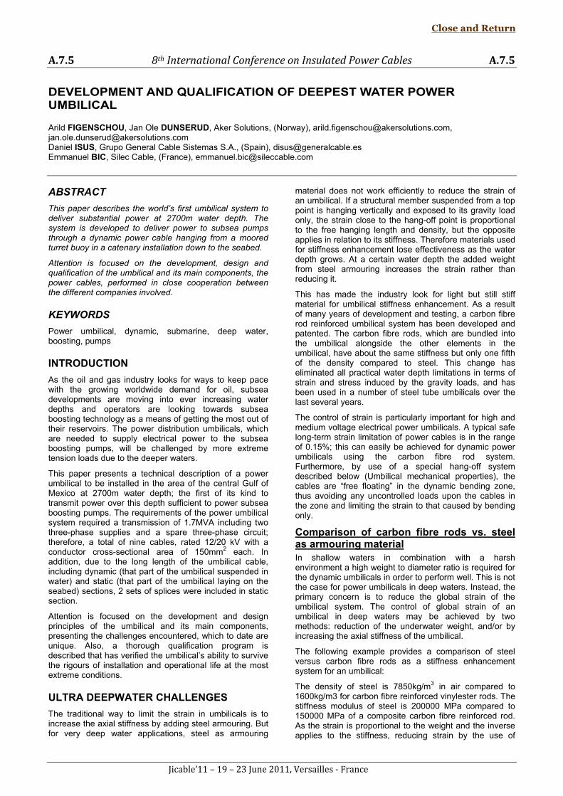
In Figure 2 the cross-section of the present umbilical is shown, including a triad formation of three-phase circuits with a total of nine cables rated 12/20 kV with a conductor cross-sectional area of 150 mm² each.
Fig. 2: Power umbilical cross-section (dynamic section – some rods are replaced with plastic fillers in
the static section)
Close and Return
A.7.5 8th International Conference on Insulated Power Cables A.7.5
Jicable’11 – 19 – 23 June 2011, Versailles - France
Table 1: Table of power umbilical components in Fig. 2
Umbilical electrical properties There is no transformation of the voltage, so with a motor voltage of 4.4kV, it is necessary to have an output voltage from the variable speed drive of 6.1kV to obtain the rated voltage for the motor. This corresponds to a voltage drop of 28% and reduces the air gap torque. This and the voltage increase due to load reduction were found to be acceptable for the operation.
The magnetic field set up by the load current will induce currents and voltages in nearby conductive elements. The induced current in the grounded elements such as screens, steel weight elements and carbon fibre rods gives additional losses that can be handled by thermal analysis to check if any elements are overheated. The voltage induced into the cores within the same circuit and into the neighbouring circuit is more complicated because it affects the operation of the pump motor. This negative effect can be cancelled by twisting the circuits within the cross-section. That method would increase the required number of splices and the cost dramatically and was rejected. Another solution is to have the 3 circuits in different layers with opposite twisting direction. This would increase the outer diameter significantly and a large number of weight elements would be required to maintain the weight to diameter ratio needed. It was therefore decided to keep the most efficient design and study more closely what impact the induced voltage would have on the operation of the motor. By use of a Finite Element method it was found that the negative sequence voltage was less than 1%. This is acceptable according to IEC 60034-26 without de-rating the motor.
The induced voltage from the neighbouring circuit also causes a variation in the air gap torque when the power frequencies are different. The impact of this was also studied and it was concluded that the amplitude of the air gap torques was maximum 2.8% and was acceptable because it was within a frequency range that was not critical for the operation.
Thermal analysis was also performed to visualize the temperature distribution in the cross-section. One of the 3 circuits was spare and it was interesting to know the temperature difference between the elements as an input to the mechanical analysis.
Umbilical mechanical properties One of the main challenges of designing a safe and reliable high power dynamic umbilical for deep water application is to control the forces and strain in the copper cores of the cables. The material properties of copper make it difficult to predict the forces over time as the
combination of material creep and temperature effects (expansion and contraction) in the copper cores makes the evaluation of the fatigue life very uncertain.
To minimize the fatigue of the cables in the dynamic bending zone, a concept was developed with the electrical power cables “free floating” in the dynamic bending zone, thus avoiding any uncontrolled loads upon the cables in the zone. The carbon fibre rods are anchored at the top hang-off, but the electrical cables run through the hang-off without any constraint and are therefore free to expand and contract. Instead of a topside cable termination, the cables are hung-off inside the umbilical with a “soft clamp” system. This system is basically a vulcanized rubber sheath that is applied to the outside of the cable over a length of ten metres, increasing the outer diameter and providing friction against the inside of the cable conduit in the umbilical, without creating a “hard point” between the surfaces. This is located some 15 to 20 metres below the bend stiffener, and becomes the hang-off point of the power cables. From this point and up through the dynamic bending zone, the cables are free to expand thermally, and are exposed to bending only, and therefore the forces upon the electrical cables become highly predictable. Descending below the hang-off point, the power cables are secured by frictional points in a special pattern over a length of 2 metres at intervals of 50 metres to counteract any long-term creep/deformation of the copper cores. This system protects the electrical cables from strain hardening and fatigue failure in the dynamic section.
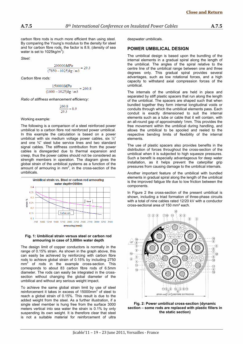
Power cable design The maximum current required by the pumps was in the order of 225 A. Due to the length of 22.7 km of one of the umbilicals and the consequent voltage drop, the supply at the host was at 6 kV approximately to achieve a voltage required by the motor terminals of 4.4 kV. These requirements were obtained by using a cable with a conductor cross-sectional area of 150 mm² and, whereas an insulation rating of 6/10 kV would have been sufficient, 12/20 kV rating was used to achieve a much lower electrical stress and consequently a greater safety factor. A drawing of the power cable is shown in Figure 3.
Fig. 3: Power cable drawing
Close and Return
A.7.5 8th International Conference on Insulated Power Cables A.7.5
Jicable’11 – 19 – 23 June 2011, Versailles - France
Item
1
2 Conductor screen
3
4 Insulation screen (non metallic)
5 Copper wires screen
6 Outer sheath
Conductor
Description
XLPE Insulation
Table 2: Table of power cable components in Fig. 3
The conductor was a multi-stranded Class 2 type design according to IEC 60228. While following the requirements of the mentioned standard, several design parameters can be adapted in order to achieve the required final conductor mechanical properties. Hence, after a prototyping and trial testing process, it was of great importance to well define and control the material type and the drawing, annealing, stranding and compacting processes. Electrolytic Tough Pitch (ETP) was used and every layer of wires was semi-compacted; in addition, no single wire weld, due to possible factory logistic limitations or breaks during production, was allowed during the whole conductor lengths manufacturing process. The final objective was to obtain proper conductor behaviour under all expected loads taken during the installation process and operational life, while also assuring the constant properties of it in the whole manufactured length.
The insulation system was constituted of a semiconductive conductor screen, Cross-Linked Polyethylene (XLPE) and a semiconductive insulation screen. The three layers were extruded at the same time by means of a triple extrusion head and the curing and cooling processes were performed in a dry nitrogen catenary line. Both semiconductive layer thicknesses were increased compared with a standard MV cable design to avoid any possible insulation damage caused by a conductor or screen copper wire embedding into those layers during the dynamic related movements.
The metallic screen was constituted of 60 copper wires laid up onto the outer semiconductive layer with a total cross-sectional area of 16 mm². This screen design was chosen after several trials, mainly taking into consideration the proper behaviour under bending fatigue and the shear load capacity between the insulation system and the outer jacket; this last property being crucial in the overall transfer of the copper conductor load through all cable layers to the external umbilical strength members (carbon fibre rods). Other types of screens, including a copper tape helicoidally applied, were tested with unsuccessful results. A High Density Polyethylene (HDPE) outer sheath was applied onto the metallic screen to protect it mechanically as well as to minimize the water diffusion to the insulation.
QUALIFICATION TESTING
Power cable qualification testing Due to the specific particularities of the project (deepness, dynamic behaviour, sea water environment…), a specific qualification testing plan was designed to simulate the mechanical and electrical conditions of the application during both operation and installation of the cable.
The first important goal of the defined testing sequences was to collect the mechanical properties of the cable both under axial tensile and compression loads. As umbilical
strength members were playing an essential role, limiting mechanical working conditions of power cable, the umbilical design was adapted according to the power cable characteristics established through testing.
Subsequently, when power cable working condition limitations were determined and imposed by the final umbilical strength members design, the second important goal was to verify the characteristic cable operation at those expected critical working conditions (with an extra safety margin) by means of mechanical testing followed by electrical testing.
Testing sequences
To verify the electrical suitability of the power cable during and after the application of an external pressure of 1.5 times the equivalent to the maximum installation water depth, the following test sequence was made on one cable sample:
• Hyperbaric Test at 410 bars for 24 hours; applying voltage on the sample while pressurized.
• Partial Discharge Test according to IEC 60502-2.
• Impulse Voltage Test according to IEC 60502-2.
• Voltage Test according to IEC 60502-2.
• Visual Inspection (dissection).
The power cable stress-strain curve under axial tensile load was obtained for information by means of tensile testing. Eventually, multiple samples from multiple manufacturing batches were tested to find any variation in batches, using the most conservative results to fine-tune the umbilical calculations.
To verify the electrical suitability of the power cable after the application of the maximum working tensile load (with an extra safety margin), the following test sequence was made on another cable sample:
• Tensile Test up to 0.3% elongation.
• Partial Discharge Test according to IEC 60502-2.
• Impulse Voltage Test according to IEC 60502-2.
• Voltage Test according to IEC 60502-2.
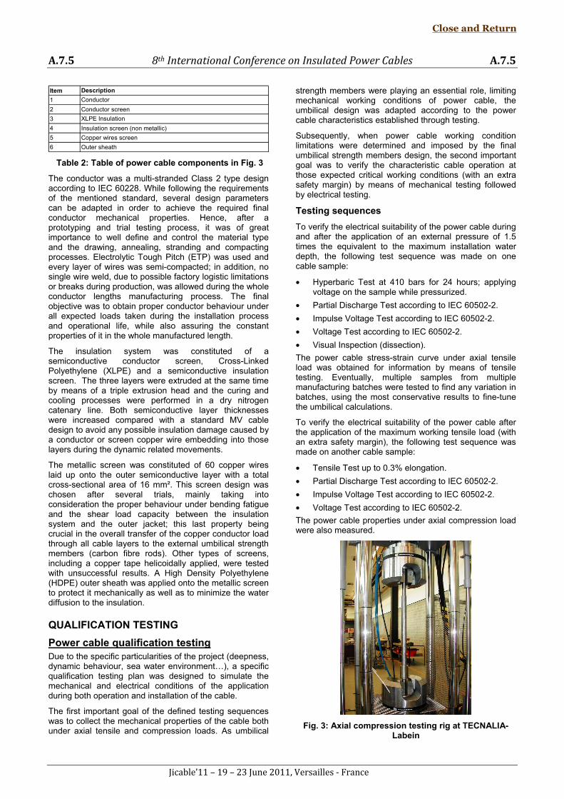
The power cable properties under axial compression load were also measured.
Fig. 3: Axial compression testing rig at TECNALIA-Labein
Close and Return
A.7.5 8th International Conference on Insulated Power Cables A.7.5
Jicable’11 – 19 – 23 June 2011, Versailles - France
To verify the electrical suitability of the power cable after the application of the maximum working compression value (with an extra safety margin) experienced in some cases due to temperature differences inside the umbilical, the following test sequence was made:
• Axial compression test up to 0.2% compression strain.
• Partial Discharge Test according to IEC 60502-2.
• Impulse Voltage Test according to IEC 60502-2.
• Voltage Test according to IEC 60502-2.
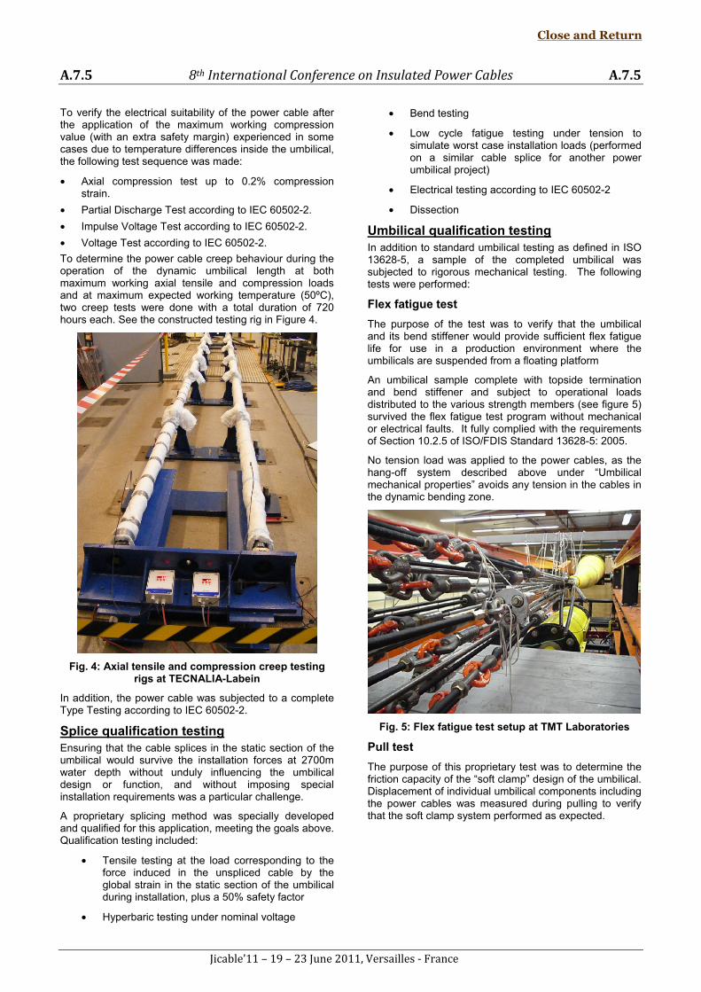
To determine the power cable creep behaviour during the operation of the dynamic umbilical length at both maximum working axial tensile and compression loads and at maximum expected working temperature (50ºC), two creep tests were done with a total duration of 720 hours each. See the constructed testing rig in Figure 4.
Fig. 4: Axial tensile and compression creep testing rigs at TECNALIA-Labein
In addition, the power cable was subjected to a complete Type Testing according to IEC 60502-2.
Splice qualification testing Ensuring that the cable splices in the static section of the umbilical would survive the installation forces at 2700m water depth without unduly influencing the umbilical design or function, and without imposing special installation requirements was a particular challenge.
A proprietary splicing method was specially developed and qualified for this application, meeting the goals above. Qualification testing included:
• Tensile testing at the load corresponding to the force induced in the unspliced cable by the global strain in the static section of the umbilical during installation, plus a 50% safety factor
• Hyperbaric testing under nominal voltage
• Bend testing
• Low cycle fatigue testing under tension to simulate worst case installation loads (performed on a similar cable splice for another power umbilical project)
• Electrical testing according to IEC 60502-2
• Dissection
Umbilical qualification testing In addition to standard umbilical testing as defined in ISO 13628-5, a sample of the completed umbilical was subjected to rigorous mechanical testing. The following tests were performed:
Flex fatigue test
The purpose of the test was to verify that the umbilical and its bend stiffener would provide sufficient flex fatigue life for use in a production environment where the umbilicals are suspended from a floating platform
An umbilical sample complete with topside termination and bend stiffener and subject to operational loads distributed to the various strength members (see figure 5) survived the flex fatigue test program without mechanical or electrical faults. It fully complied with the requirements of Section 10.2.5 of ISO/FDIS Standard 13628-5: 2005.
No tension load was applied to the power cables, as the hang-off system described above under “Umbilical mechanical properties” avoids any tension in the cables in the dynamic bending zone.
Fig. 5: Flex fatigue test setup at TMT Laboratories
Pull test
The purpose of this proprietary test was to determine the friction capacity of the “soft clamp” design of the umbilical. Displacement of individual umbilical components including the power cables was measured during pulling to verify that the soft clamp system performed as expected.
Close and Return
A.7.5 8th International Conference on Insulated Power Cables A.7.5
Jicable’11 – 19 – 23 June 2011, Versailles - France
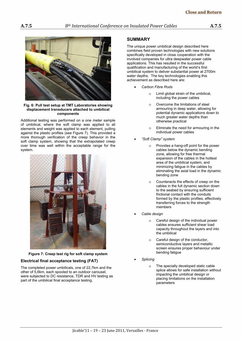
Fig. 6: Pull test setup at TMT Laboratories showing displacement transducers attached to umbilical
components
Additional testing was performed on a one meter sample of umbilical, where the soft clamp was applied to all elements and weight was applied to each element, pulling against the plastic profiles (see Figure 7). This provided a more thorough verification of the creep behavior in the soft clamp system, showing that the extrapolated creep over time was well within the acceptable range for the system.
Figure 7: Creep test rig for soft clamp system
Electrical final acceptance testing (FAT)
The completed power umbilicals, one of 22,7km and the other of 5,6km, each spooled to an outdoor carousel, were subjected to DC resistance, TDR and HV testing as part of the umbilical final acceptance testing.
SUMMARY
The unique power umbilical design described here combines field proven technologies with new solutions specifically developed in close cooperation with the involved companies for ultra deepwater power cable applications. This has resulted in the successful qualification and manufacturing of the world’s first umbilical system to deliver substantial power at 2700m water depths. The key technologies enabling this achievement as described here are:
• Carbon Fibre Rods
o Limit global strain of the umbilical, including the power cables
o Overcome the limitations of steel armouring in deep water, allowing for potential dynamic applications down to much greater water depths than otherwise practical
o Eliminate the need for armouring in the individual power cables
• “Soft Clamp” system
o Provides a hang-off point for the power cables below the dynamic bending zone, allowing for free thermal expansion of the cables in the hottest area of the umbilical system, and minimizing fatigue in the cables by eliminating the axial load in the dynamic bending zone
o Counteracts the effects of creep on the cables in the full dynamic section down to the seabed by ensuring sufficient frictional contact with the conduits formed by the plastic profiles, effectively transferring forces to the strength members
• Cable design
o Careful design of the individual power cables ensures sufficient shear load capacity throughout the layers and into the umbilical
o Careful design of the conductor, semiconductive layers and metallic screen ensures proper behaviour under bending fatigue
• Splicing
o The specially developed static cable splice allows for safe installation without impacting the umbilical design or placing limitations on the installation parameters
Close and Return