Embed Size (px)
DESCRIPTION
thermo
Citation preview
REHEAT CYCLE
I. DiscussionFor attaining greater thermal efficiencies when the initial pressure of
steam is raised beyond 42 bar, it was observed that the resulting condition of steam after expansion is increasingly wetter and exceeded the safe limit of 12% condensation. It is therefore, necessary to reheat the steam after expansion that fell within the region of permissible wetness.
Reheating of steam is now universally used when the steam fed is at high pressure and temperature conditions. In actual practice, reheating mechanisms improve the efficiency of the cycle by about 5%. A second reheat system may be added if the initial steam condition is so severe but it is otherwise not advisable to be used because of the costs.
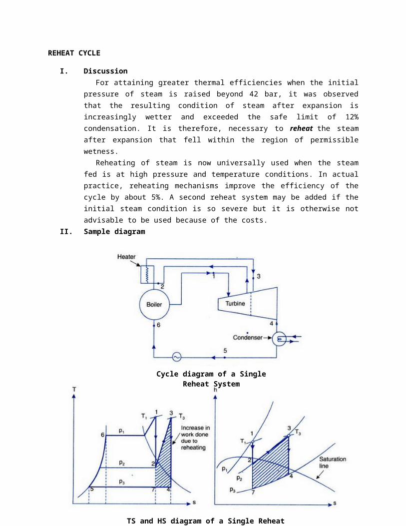
II. Sample diagram
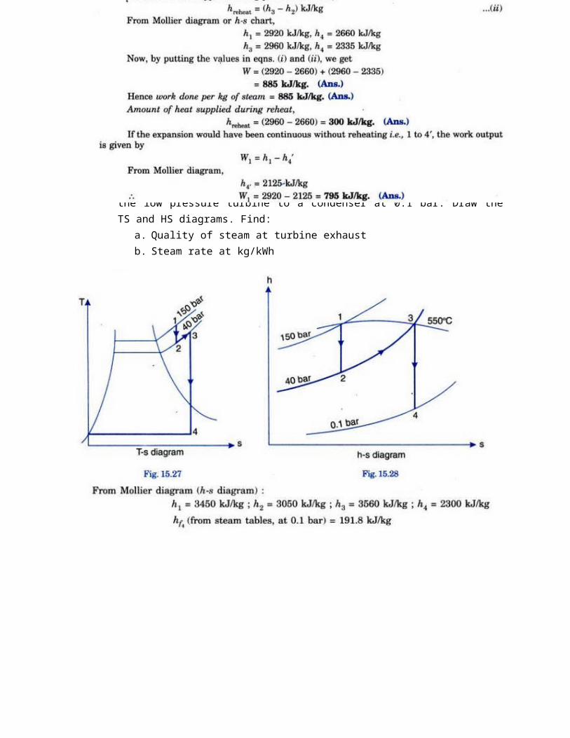
TS and HS diagram of a Single Reheat System
Cycle diagram of a Single Reheat System

The cycle diagram shows the formation of steam in the boiler. The steam at point 1 (P1, T1) enters the turbine and expands isentropically to a certain pressure P2 and temperature T2. From point 2, the whole steam is drawn out of the turbine and is reheated in a reheater at a temperature T3. This reheated steam is then readmitted to the turbine where it is expanded to condenser pressure isentropically.
Notes:(1) The reheater may be incorporated in the walls of the main boiler; it
may be a separately fired superheater or it may be by a coil carrying high-pressure superheated steam, this system being analogous to a steam jacket.
(2) Reheating should be done at optimum pressure because if the steam is reheated early in its expansion the then additional quantity of heat supplied will be small and thus thermal efficiency will gain small; and if the reheating is done at a fairly low pressure, then although a large amount of additional heat is supplied, the steam will have a high degree of superheat, thus a large proportion of heat supplied in the reheating process will be thrown to waste in the condenser.
III. Working Equations
Thermal Efficiency with “reheating” neglecting pump work:
Heat supplied=(h1−hf 4 )+(h3−h2)Heat rejected=(h4−hf 4 )Work doneby the turbine=(h1−hf 4 )+(h3−h2 )−(h4−h f 4 )
¿ (h1−h2 )+(h3−h4 )Thus , thermal efficiency ,ηthermal=(h1−h2)+ (h3−h4 )(h1−h f 4 )+(h3−h2)
If pumpwork is ,W p=−V sat (P5−P6 )ηthermal=(h1−h2 )+(h3−h4 )−W p
(h1−h f 4 )+(h3−h2 )
IV. Sample Problems

1. Steam at a pressure of 15 bar and 250 degree Celsius is expanded through a turbine at first to a pressure of 4 bar. It is then reheated at constant pressure to the initial temperature of 250 degree Celsius and is finally expanded to 0.1 bar. Using Mollier chart, estimate the work done per kg of steam flowing through the turbine and amount of heat supplied during the process of reheat. Compare the work output when the
expansion is direct from 15 bar to 0.1 bar without any reheat. Assume all expansion processes to be isentropic.
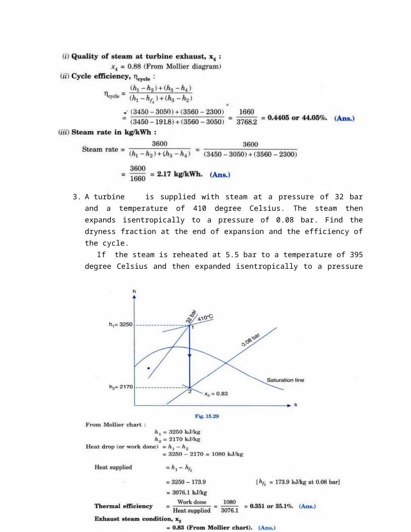
2. A steam power plant operates on a theoretical reheat cycle. Steam at boiler at 150 bar, 550 degree Celsius expands through the high pressure turbine. It is reheated at a constant pressure of 40 bar to 550 degree Celsius and expands through the low pressure turbine to a condenser at 0.1 bar. Draw the TS and HS diagrams. Find:
a. Quality of steam at turbine exhaustb. Steam rate at kg/kWh
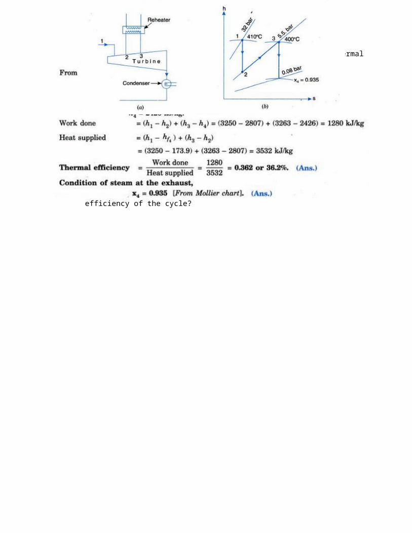
3. A turbine is supplied with steam at a pressure of 32 bar and a temperature of 410 degree Celsius. The steam then expands isentropically to a pressure of 0.08 bar. Find the dryness fraction at the end of expansion and the efficiency of the cycle.
If the steam is reheated at 5.5 bar to a temperature of 395 degree Celsius and then expanded isentropically to a pressure of 0.08 bar, what will be the dryness fraction and thermal efficiency of the cycle?
INTERNAL COMBUSTION ENGINES:
OTTO CYCLE
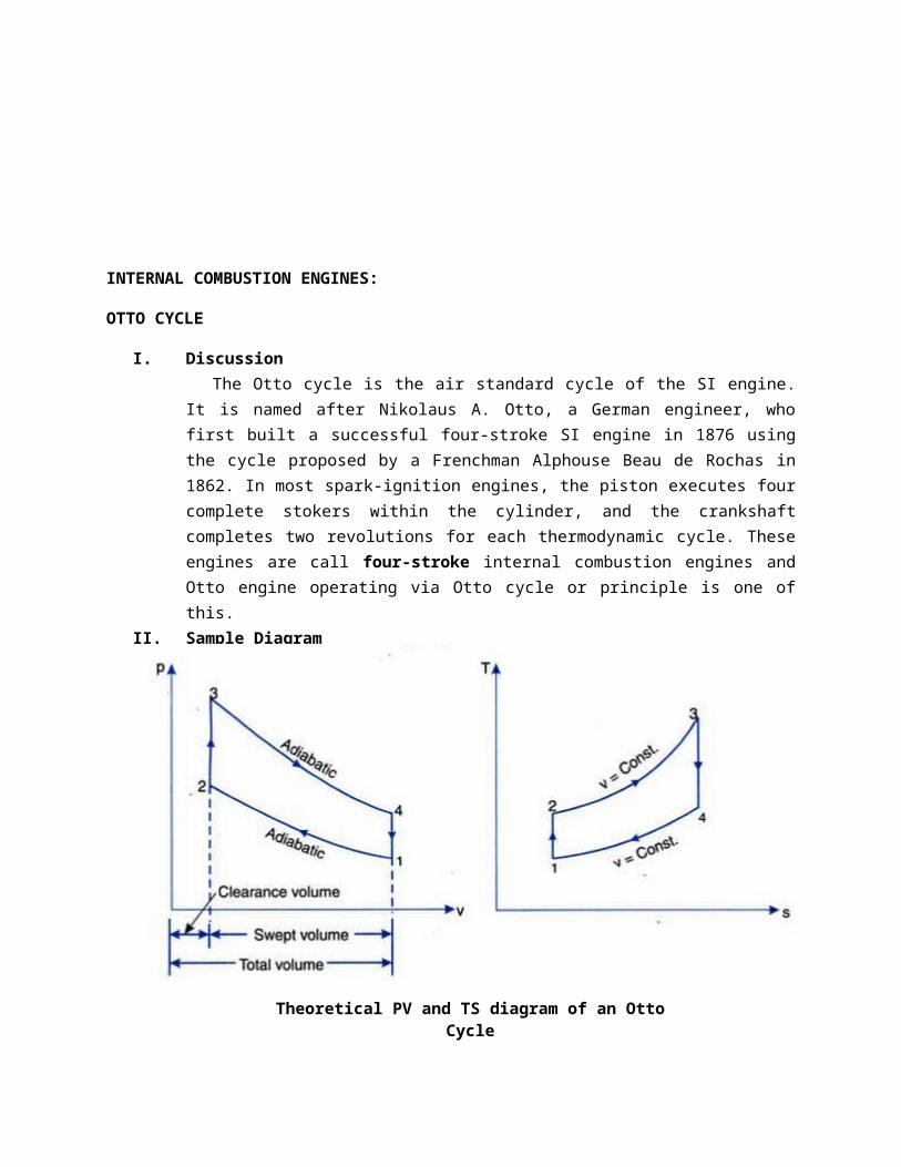
I. DiscussionThe Otto cycle is the air standard cycle of the SI engine. It is named
after Nikolaus A. Otto, a German engineer, who first built a successful four-stroke SI engine in 1876 using the cycle proposed by a Frenchman Alphouse Beau de Rochas in 1862. In most spark-ignition engines, the piston executes four complete stokers within the cylinder, and the crankshaft completes two revolutions for each thermodynamic cycle. These engines are call four-stroke internal combustion engines and Otto engine operating via Otto cycle or principle is one of this.
II. Sample Diagram
III. Working Equations1. The point 1 represents that cylinder is full of air with volume V1,
pressure P1 and absolute temperature T1.2. Line 1-2 represents the adiabatic compression of air due to which P1,
V1, and T1 changes to P2, V2 and T2.3. Line 2-3 shows the supply of heat to the air at constant volume so that
P2 and T2 changes to P3 and T2 (V=constant so V2 is the same with V3).4. Line 3-4 represents the adiabatic expansion of the air. During
expansion, P3, V3 and T3 changes to P4, V4 or V1 and T4 respectively.5. Line 4-1 shows the rejection of heat by air at constant volume until
original state (point 1) is attained.
Heat supplied at constant V=C v (T 3−T2 )Heat rejected at constant V=C v (T 4−T 1 )
Theoretical PV and TS diagram of an Otto Cycle
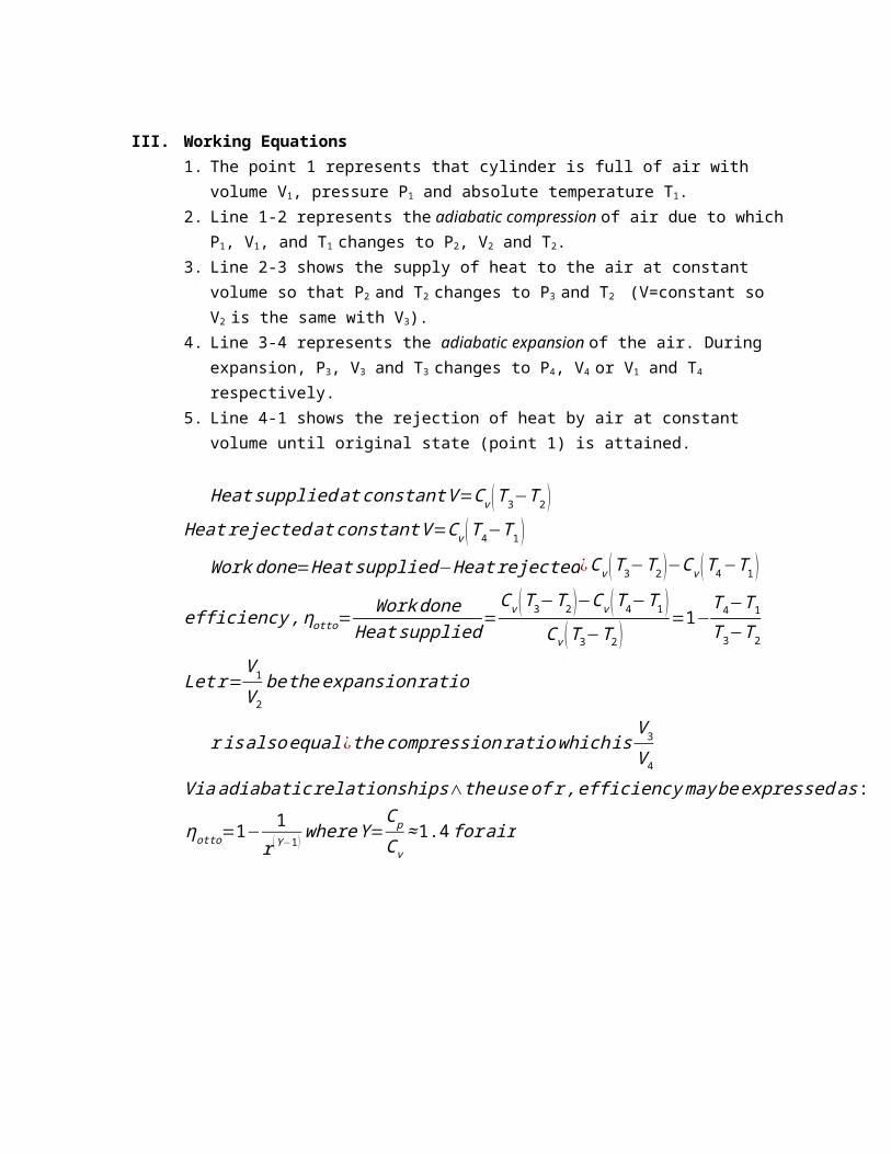
Work done=Heat supplied−Heat rejected¿C v (T 3−T 2 )−C v (T 4−T 1 )
efficiency ,ηotto=Work done
Heat supplied=C v (T 3−T 2)−C v (T 4−T1 )
C v (T 3−T 2 )=1−
T 4−T1T3−T 2
Let r=V 1
V 2
be the expansion ratio
r is also equal¿ the compressionratio which isV 3
V 4
Viaadiabatic relationships∧theuse of r , efficiency maybeexpressed as :
ηotto=1−1
r (Υ−1 ) whereΥ=Cp
C v
≈1.4 for air
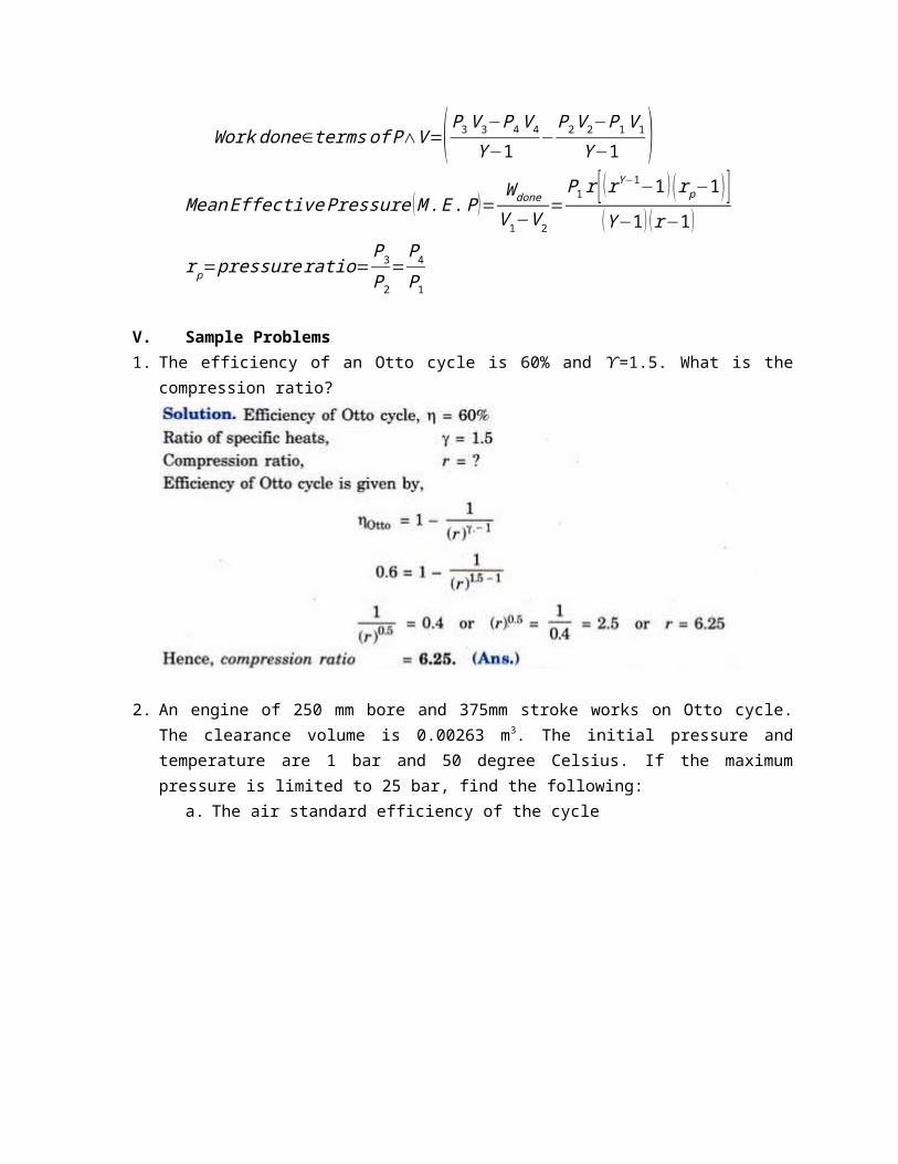
Work done∈terms of P∧V=( P3V 3−P4V 4
Υ−1−P2V 2−P1V 1
Υ−1 )MeanEffective Pressure (M . E . P )=
W done
V 1−V 2
=P1r [ (rΥ−1−1 ) (r p−1 ) ]
(Υ−1 ) (r−1 )
r p=pressure ratio=P3P2
=P4P1
V. Sample Problems1. The efficiency of an Otto cycle is 60% and 𝛶=1.5. What is the compression
ratio?
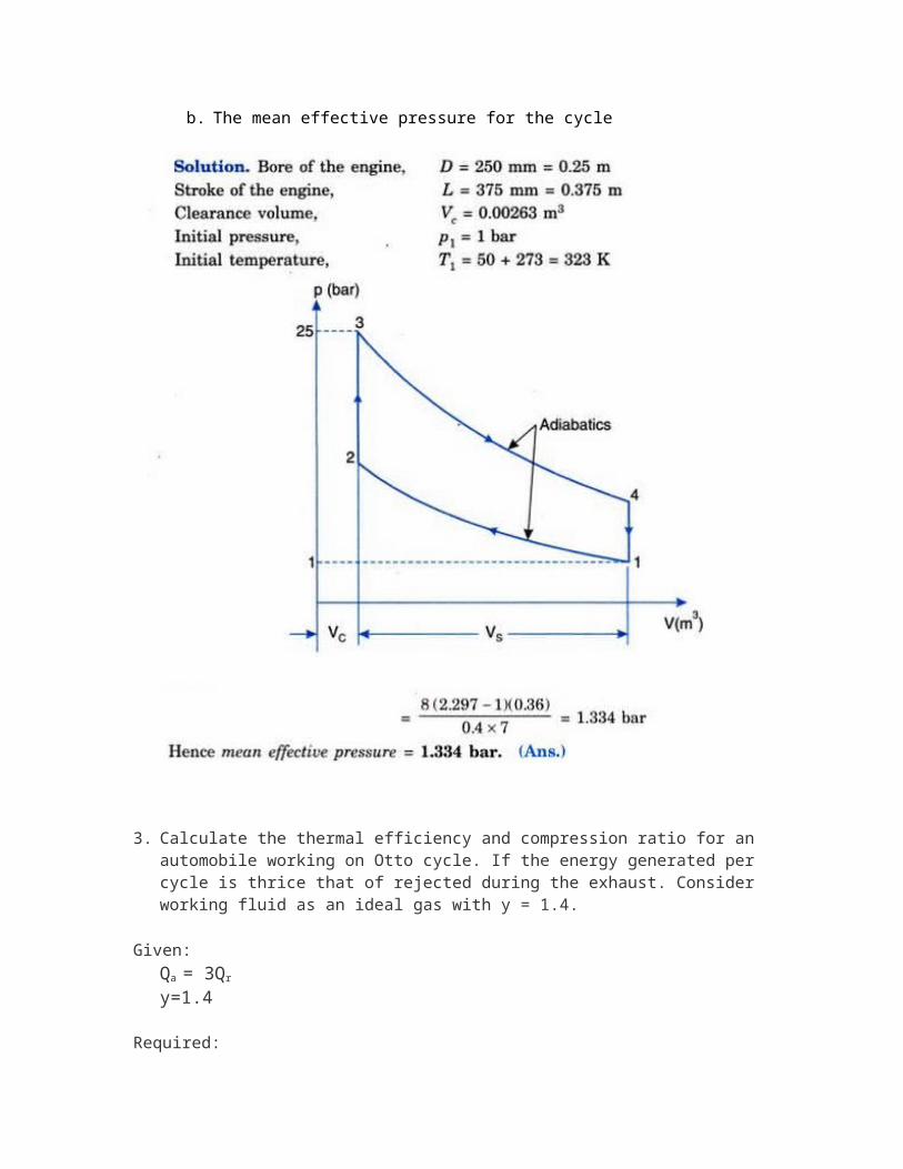
2. An engine of 250 mm bore and 375mm stroke works on Otto cycle. The clearance volume is 0.00263 m3. The initial pressure and temperature are 1 bar and 50 degree Celsius. If the maximum pressure is limited to 25 bar, find the following:
a. The air standard efficiency of the cycle
b. The mean effective pressure for the cycle
3. Calculate the thermal efficiency and compression ratio for an automobile working on Otto cycle. If the energy generated per cycle is thrice that of rejected during the exhaust. Consider working fluid as an ideal gas with y = 1.4.
Given: Qa = 3Qr
y=1.4
Required:a. Efficiency
b. Compression ratio
Solution:a. Since we have
n=Qa−Qr
Qa
n=3Qr−Qr
3Qr
n=23=0.6667=66 .67%
b. We also have
n=1−1
r y−1
. 6667=1−1r1. 4−1
r=15.59
References:
1. Thermal Engineering by R.K. Rajput2. Thermodynamics: An Engineering Approach by Y. Cengel and M.
Boles