Embed Size (px)
Citation preview
1© Crown copyright 2019 All times are UTC
AAIB Bulletin VP-CPS EW/C2019/02/04
ACCIDENT
Aircraft Type and Registration: Eurocopter EC135T1, VP-CPS
No & Type of Engines: 2 Turbomeca Arrius 2B1A turboshaft engines
Year of Manufacture: 1999
Date & Time (UTC): 26 February 2019 at 1631 hrs
Location: Owen Roberts International Airport, Cayman Islands
Type of Flight: Training and search
Persons on Board: Crew - 3 Passengers - None
Injuries: Crew - 3 (Minor) Passengers - N/A
Nature of Damage: Damage to tail boom, landing gear and transmission deck
Commander’s Licence: Commercial Pilot’s Licence
Commander’s Age: 58 years
Commander’s Flying Experience: 7,842 hours (of which 3,879 were on type) Last 90 days - 56 hours Last 28 days - 22 hours
Information Source: AAIB Field Investigation
Synopsis
At the start of a ‘training and search’ detail in the Cayman Islands, the pilot lifted the helicopter to a height of approximately four feet and felt the cyclic control stick shake and exert a rearwards force. He immediately lowered the collective lever and the helicopter landed heavily, sustaining damage to the tail boom, landing gear and transmission deck. A subsequent inspection of the helicopter revealed the longitudinal axis of the main rotor actuator had failed. A tie bar within the actuator had suffered pitting corrosion, leading to intercrystalline corrosion and cracking which resulted in overload failure of the remaining material. It is possible that moisture penetrated into the actuator and allowed the tie bar to corrode. The environment conditions of the Cayman Islands may have contributed to the corrosion. Safety actions have been taken to ensure the continued airworthiness of the worldwide fleet and to review the design of the actuator to prevent moisture ingress.
History of the flight
On the day of the accident flight the helicopter had been prepared with dual controls, ready for a planned instrument-flying practice-mission. It was positioned on the dolly used for moving the helicopter in and out of the hangar at Owen Roberts International Airport, Cayman Islands. Prior to departure the crew were informed of a search requirement for a vessel in Cayman Island waters and so a Tactical Flight Officer (TFO) was added to the crew to enable both the search and the instrument-flying practice to be completed in the
2© Crown copyright 2019 All times are UTC
AAIB Bulletin VP-CPS EW/C2019/02/04
same mission. The commander was the Pilot Flying (PF) in the right seat and the safety pilot (Pilot Monitoring) was in the left seat, with the TFO in the rear of the cabin.
Pre-flight checks were completed by a challenge and response system between the commander and the TFO. The weather was partly cloudy, 29°C with 13 kt wind from 090°. At 1631 hrs local the pilot lifted the helicopter to a height of approximately four feet above the dolly and felt the cyclic control stick shake and then a strong rearwards force, which he was unable to overcome. The pilot immediately lowered the collective lever, landing heavily, and moved both throttle twist grips to idle, switched off the engines and applied the rotor brake. A PAN call was made to ATC requesting fire service assistance.
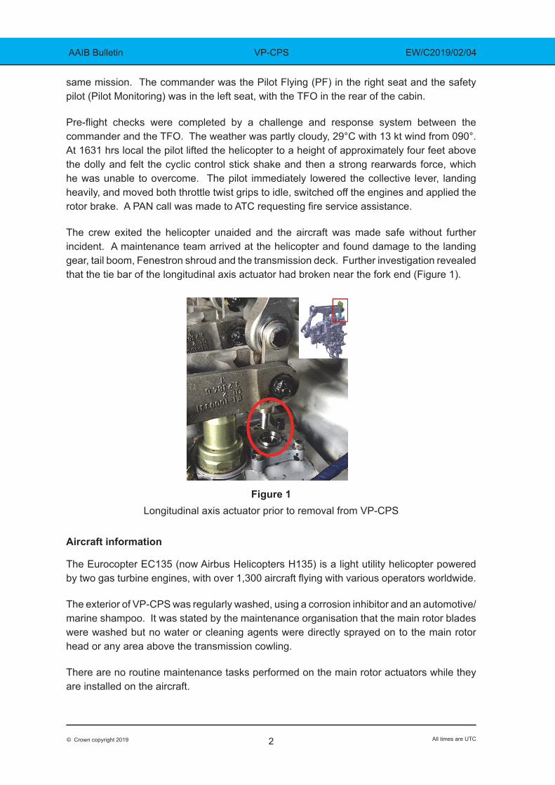
The crew exited the helicopter unaided and the aircraft was made safe without further incident. A maintenance team arrived at the helicopter and found damage to the landing gear, tail boom, Fenestron shroud and the transmission deck. Further investigation revealed that the tie bar of the longitudinal axis actuator had broken near the fork end (Figure 1).
Figure 1
Longitudinal axis actuator prior to removal from VP-CPS
Aircraft information
The Eurocopter EC135 (now Airbus Helicopters H135) is a light utility helicopter powered by two gas turbine engines, with over 1,300 aircraft flying with various operators worldwide.
The exterior of VP-CPS was regularly washed, using a corrosion inhibitor and an automotive/marine shampoo. It was stated by the maintenance organisation that the main rotor blades were washed but no water or cleaning agents were directly sprayed on to the main rotor head or any area above the transmission cowling.
There are no routine maintenance tasks performed on the main rotor actuators while they are installed on the aircraft.
3© Crown copyright 2019 All times are UTC
AAIB Bulletin VP-CPS EW/C2019/02/04
Main rotor control system
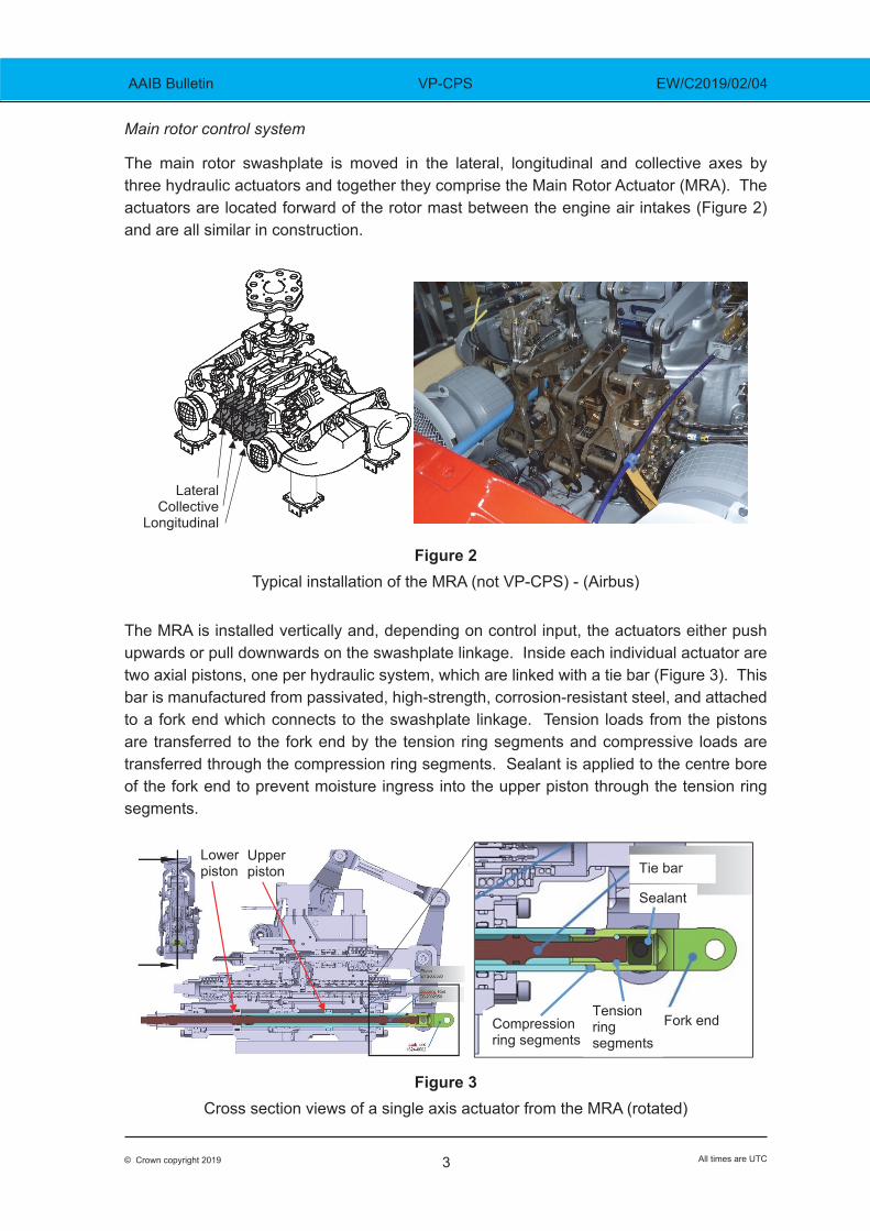
The main rotor swashplate is moved in the lateral, longitudinal and collective axes by three hydraulic actuators and together they comprise the Main Rotor Actuator (MRA). The actuators are located forward of the rotor mast between the engine air intakes (Figure 2) and are all similar in construction.
Lateral Collective
Longitudinal
Figure 2Typical installation of the MRA (not VP-CPS) - (Airbus)
The MRA is installed vertically and, depending on control input, the actuators either push upwards or pull downwards on the swashplate linkage. Inside each individual actuator are two axial pistons, one per hydraulic system, which are linked with a tie bar (Figure 3). This bar is manufactured from passivated, high-strength, corrosion-resistant steel, and attached to a fork end which connects to the swashplate linkage. Tension loads from the pistons are transferred to the fork end by the tension ring segments and compressive loads are transferred through the compression ring segments. Sealant is applied to the centre bore of the fork end to prevent moisture ingress into the upper piston through the tension ring segments.
Fork end
Tie bar Lower piston
Tension ring segments
Upper piston
Compression ring segments
Sealant
Figure 3Cross section views of a single axis actuator from the MRA (rotated)
4© Crown copyright 2019 All times are UTC
AAIB Bulletin VP-CPS EW/C2019/02/04
To enable the replacement of an actuator on the helicopter without the need to adjust the swashplate linkage, the length of the actuator is controlled to +/- 0.1mm. To achieve this tolerance, the completed actuator length is measured, and new compression ring segments (Figure 4) are fitted to achieve the length tolerance. The replacements are chosen from a group with a range of different lengths [X].
X 1.6mm / 0.7mm Gap
Figure 4Compression ring segments
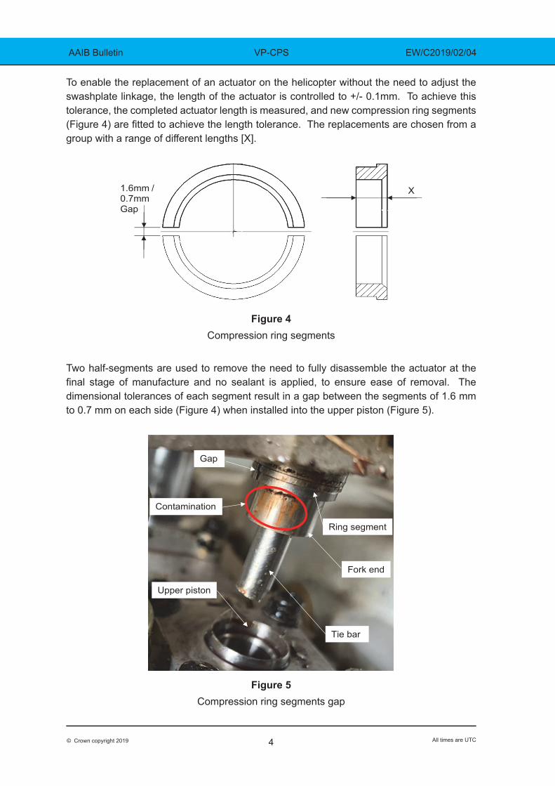
Two half-segments are used to remove the need to fully disassemble the actuator at the final stage of manufacture and no sealant is applied, to ensure ease of removal. The dimensional tolerances of each segment result in a gap between the segments of 1.6 mm to 0.7 mm on each side (Figure 4) when installed into the upper piston (Figure 5).
Gap
Tie bar
Fork end
Ring segment
Upper piston
Contamination
Figure 5Compression ring segments gap
5© Crown copyright 2019 All times are UTC
AAIB Bulletin VP-CPS EW/C2019/02/04
Aircraft examination
The MRA was removed from the helicopter and sent to the component manufacturer for disassembly and inspection. The overall external condition was typical for the equipment, which had completed 18 years in service and 6,561 flying hours. The lateral and longitudinal axis tie bars had been replaced in 2005 after 576 flying hours, due to damaged threads. The tie bar of the longitudinal axis actuator had fractured approximately 30 mm from the end attached to the fork fitting, where the cross-section changes for an ‘O-ring’ seal (Figure 6).
6
Figure 5
Compression ring segments gap
Aircraft examination
All three MRAs were removed from the helicopter and sent to the component manufacturer for disassembly and inspection. The external condition of the actuators was deemed to be good after 18 years in service and completion of 6,561 flying hours. The lateral and longitudinal coupling rods had been replaced in 2005 after 576 flying hours due to damaged threads. The coupling rod of the longitudinal actuator had fractured approximately 30 mm from the end attached to the fork fitting, where the cross-section changes for an O-ring seal (Figure 6).
Figure 6 Coupling rod fracture location
Analysis of the material found adjacent to the fracture on the coupling rod (Figure 7) revealed a high sodium and chlorine content, with similar deposits found on the other actuator coupling
Fracture
Gap
Coupling rod
Fork end
Ring segment
Upper piston
Corrosive material
Figure 6Tie bar fracture location
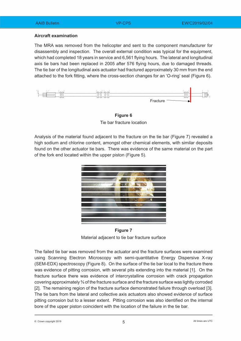
Analysis of the material found adjacent to the fracture on the tie bar (Figure 7) revealed a high sodium and chlorine content, amongst other chemical elements, with similar deposits found on the other actuator tie bars. There was evidence of the same material on the part of the fork end located within the upper piston (Figure 5).
Figure 7
Material adjacent to tie bar fracture surface
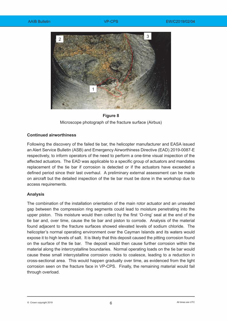
The failed tie bar was removed from the actuator and the fracture surfaces were examined using Scanning Electron Microscopy with semi-quantitative Energy Dispersive X-ray (SEM-EDX) spectroscopy (Figure 8). On the surface of the tie bar local to the fracture there was evidence of pitting corrosion, with several pits extending into the material [1]. On the fracture surface there was evidence of intercrystalline corrosion with crack propagation covering approximately ¾ of the fracture surface and the fracture surface was lightly corroded [2]. The remaining region of the fracture surface demonstrated failure through overload [3]. The tie bars from the lateral and collective axis actuators also showed evidence of surface pitting corrosion but to a lesser extent. Pitting corrosion was also identified on the internal bore of the upper piston coincident with the location of the failure in the tie bar.
6© Crown copyright 2019 All times are UTC
AAIB Bulletin VP-CPS EW/C2019/02/04
1
2 3
Figure 8Microscope photograph of the fracture surface (Airbus)
Continued airworthiness
Following the discovery of the failed tie bar, the helicopter manufacturer and EASA issued an Alert Service Bulletin (ASB) and Emergency Airworthiness Directive (EAD) 2019-0087-E respectively, to inform operators of the need to perform a one-time visual inspection of the affected actuators. The EAD was applicable to a specific group of actuators and mandates replacement of the tie bar if corrosion is detected or if the actuators have exceeded a defined period since their last overhaul. A preliminary external assessment can be made on aircraft but the detailed inspection of the tie bar must be done in the workshop due to access requirements.
Analysis
The combination of the installation orientation of the main rotor actuator and an unsealed gap between the compression ring segments could lead to moisture penetrating into the upper piston. This moisture would then collect by the first ‘O-ring’ seal at the end of the tie bar and, over time, cause the tie bar and piston to corrode. Analysis of the material found adjacent to the fracture surfaces showed elevated levels of sodium chloride. The helicopter’s normal operating environment over the Cayman Islands and its waters would expose it to high levels of salt. It is likely that this deposit caused the pitting corrosion found on the surface of the tie bar. The deposit would then cause further corrosion within the material along the intercrystalline boundaries. Normal operating loads on the tie bar would cause these small intercystalline corrosion cracks to coalesce, leading to a reduction in cross-sectional area. This would happen gradually over time, as evidenced from the light corrosion seen on the fracture face in VP-CPS. Finally, the remaining material would fail through overload.
7© Crown copyright 2019 All times are UTC
AAIB Bulletin VP-CPS EW/C2019/02/04
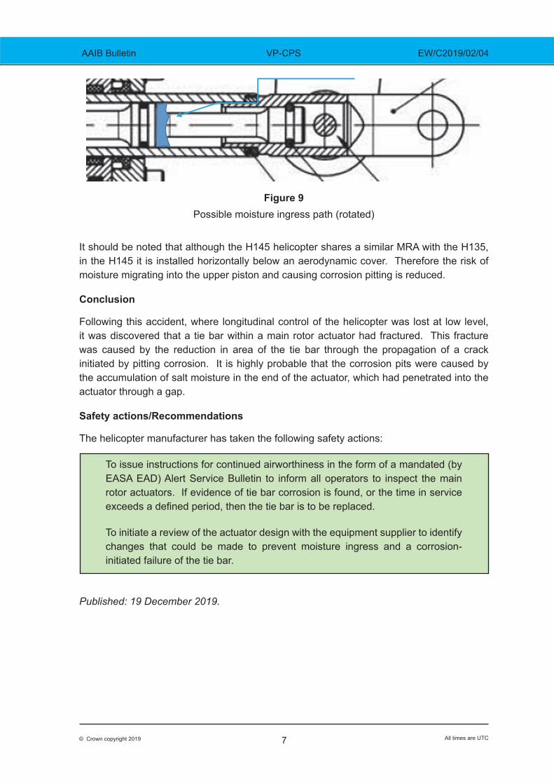
Figure 9Possible moisture ingress path (rotated)
It should be noted that although the H145 helicopter shares a similar MRA with the H135, in the H145 it is installed horizontally below an aerodynamic cover. Therefore the risk of moisture migrating into the upper piston and causing corrosion pitting is reduced.
Conclusion
Following this accident, where longitudinal control of the helicopter was lost at low level, it was discovered that a tie bar within a main rotor actuator had fractured. This fracture was caused by the reduction in area of the tie bar through the propagation of a crack initiated by pitting corrosion. It is highly probable that the corrosion pits were caused by the accumulation of salt moisture in the end of the actuator, which had penetrated into the actuator through a gap.
Safety actions/Recommendations
The helicopter manufacturer has taken the following safety actions:
To issue instructions for continued airworthiness in the form of a mandated (by EASA EAD) Alert Service Bulletin to inform all operators to inspect the main rotor actuators. If evidence of tie bar corrosion is found, or the time in service exceeds a defined period, then the tie bar is to be replaced.
To initiate a review of the actuator design with the equipment supplier to identify changes that could be made to prevent moisture ingress and a corrosion-initiated failure of the tie bar.
Published: 19 December 2019.