Embed Size (px)
Citation preview

Aalborg University
E-Studyboard
Fredrik Bajers Vej 7 DK-9220 Aalborg Øst Phone +45 96 35 87 00
Title: Cooperating LEGO-robotsTheme: Device- and/or system constructionProject period: 2. September - 16. December 2003
Project group:
E510
Group members:
Palle Ditlevsen
Jakob Sandholt Klemmensen
Martin Nygaard Kragelund
Daniel Klokmose Nielsen
Rasmus Stougaard Nielsen
Claus Kousgaard Villumsen
Supervisor:
Ove Andersen
Publications: 9Pages: 154Finished: 16. December 2003
Abstract
This report documents the development ofa system that searches and maps a simplemaze utilizing LEGO Mindstorms robots.An analysis of the requirements to the sys-tem was conducted and three coherent sub-systems were developed using Object Ori-ented Analyzes & Design; namely a Clientapplication, that handles all user communi-cation and general control, a server applica-tion that handles all search routines and guid-ance of the robots, and finally the constructedrobots that navigates and detects vertices inthe maze according to instructions passedfrom the server. Due to lack of time a lim-ited version of the design was implementedand tested. The conclusion outlines which ofthe designed functionalities that was success-fully implemented and gives an assessmentof the necessary steps towards a completionof the system.

.

Preface
This report is written by the project group E510 at the Institute of Electronic Systems, AalborgUniversity, Denmark, during the 5th semester. This semesters theme is “Device and/or systemconstruction” and the group has chosen to work on the project proposal “Cooperating LEGOrobots”. This report documents a solution to the problem in the project proposal.This report is divided into 3 parts: Main report, appendixes, and tests. The main report can be readfrom start to end. Details and specific design is explained in appendixes. The figure on page IVillustrates the connections between the main report, appendixes and tests.This report is primarily written for members of the group, the supervisor and the censor. Secon-darily people with special interest in LEGO Mindstorms and how to use this kit for other purposesthan play might benefit from this report.In chapter 1 a description of the problem of concern is expressed. Furthermore, the system that willbe developed is defined. Chapter 2 concerns the analysis of the requirements to the system to bedeveloped. The system is divided into 3 nodes whose functionality is described through use-cases.Chapter 3 explains the system behavior using activity diagrams. An overall strategy for designingthe 3 nodes is introduced. Each of the 3 nodes is analyzed, designed, implemented and tested inthe chapters 4, 5 and 6. An acceptance test to validate the the outcome of the developed systemis performed. Appendix holds a description of the methods used and how a robot is constructed.Tree appendix containing design details from each of the nodes is found too. After appendix anumber of test reports is listed.Classes these will be indicated as follows: Class and interface classes: IFClass. Furthermore,objects will be indicated like this: :object. Methods will be indicated as: method. All syntaxand semantics used in this reports is described in appendix A.Throughout this report citations are indicated with e.g. [Eriksson & Penker 1998, page number].The bibliography is sorted alphabetically after the authors surname.
Aalborg University, 16. of December 2003.
———————————– ———————————–
Palle Ditlevsen Jakob Sandholt Klemmensen
———————————– ———————————–
Martin Nygaard Kragelund Daniel Klokmose Nielsen
———————————– ———————————–
Rasmus Stougaard Nielsen Claus Kousgaard Villumsen
III

Test of Server nodeTest report III on page 139
Acceptance test specification
Test of Robot node
Test of sensors
Robot
Server
Client
Exploring the Maze
Distance Measuring sensor
Robot construction
Methods
Conclusion
Acceptance test
The Robot node
The Server node
The Client node
Basic design of the nodes
Requirement analysis
Introduction
Test report V on page 151
Test report I on page 129
Appendix G on page 111
Appendix F on page 89
Appendix E on page 81
Appendix D on page 77
Appendix C on page 73
Appendix B on page 63
Appendix A on page 57
Chapter 8 on page 53
Chapter 7 on page 51
Chapter 6 on page 45
Chapter 5 on page 37
Chapter 4 on page 29
Chapter 3 on page 21
Chapter 2 on page 7
Chapter 1 on page 1
Appendix H on page 123
Communication between nodes
Test of Client nodeTest report II on page 137
Test report IV on page 147
IV

Contents
1 Introduction 11.1 The problem of concern . . . . . . . . . . . . . . . . . . . . . . . . . . . . . . . 11.2 Possible solutions . . . . . . . . . . . . . . . . . . . . . . . . . . . . . . . . . . 11.3 System definition . . . . . . . . . . . . . . . . . . . . . . . . . . . . . . . . . . 3
2 Requirement analysis 72.1 General description . . . . . . . . . . . . . . . . . . . . . . . . . . . . . . . . . 72.2 Functional demands . . . . . . . . . . . . . . . . . . . . . . . . . . . . . . . . . 92.3 System limitations . . . . . . . . . . . . . . . . . . . . . . . . . . . . . . . . . 162.4 System future . . . . . . . . . . . . . . . . . . . . . . . . . . . . . . . . . . . . 172.5 User profile . . . . . . . . . . . . . . . . . . . . . . . . . . . . . . . . . . . . . 172.6 Interface demands . . . . . . . . . . . . . . . . . . . . . . . . . . . . . . . . . . 18
3 Basic design of the nodes 213.1 Typical scenarios . . . . . . . . . . . . . . . . . . . . . . . . . . . . . . . . . . 213.2 Main strategy . . . . . . . . . . . . . . . . . . . . . . . . . . . . . . . . . . . . 27
4 The Client node 294.1 Analysis of the Client node . . . . . . . . . . . . . . . . . . . . . . . . . . . . . 294.2 Design of the Client node . . . . . . . . . . . . . . . . . . . . . . . . . . . . . . 334.3 Implementation of the Client node . . . . . . . . . . . . . . . . . . . . . . . . . 344.4 Test of the Client node . . . . . . . . . . . . . . . . . . . . . . . . . . . . . . . 35
5 The Server node 375.1 Analysis of the Server Node . . . . . . . . . . . . . . . . . . . . . . . . . . . . 375.2 Design of the Server Node . . . . . . . . . . . . . . . . . . . . . . . . . . . . . 395.3 Test of the Server node . . . . . . . . . . . . . . . . . . . . . . . . . . . . . . . 43
6 The Robot node 456.1 Analysis of the Robot Node . . . . . . . . . . . . . . . . . . . . . . . . . . . . . 456.2 Design of the Robot Node . . . . . . . . . . . . . . . . . . . . . . . . . . . . . 466.3 Implementation of the Robot node . . . . . . . . . . . . . . . . . . . . . . . . . 506.4 Test of the Robot node . . . . . . . . . . . . . . . . . . . . . . . . . . . . . . . 50
7 Acceptance test 51
8 Conclusion 53
Bibliography 55
V

CONTENTS
Appendix 57
A Methods 57A.1 Strategy . . . . . . . . . . . . . . . . . . . . . . . . . . . . . . . . . . . . . . . 57A.2 UML diagrams . . . . . . . . . . . . . . . . . . . . . . . . . . . . . . . . . . . 59
B Robot construction 63B.1 LEGO Mindstorms . . . . . . . . . . . . . . . . . . . . . . . . . . . . . . . . . 63B.2 Analysis of sensor placements . . . . . . . . . . . . . . . . . . . . . . . . . . . 66B.3 Placing the sensors . . . . . . . . . . . . . . . . . . . . . . . . . . . . . . . . . 67B.4 Physical design of robot . . . . . . . . . . . . . . . . . . . . . . . . . . . . . . . 69B.5 Conclusion . . . . . . . . . . . . . . . . . . . . . . . . . . . . . . . . . . . . . 72
C Distance Measuring sensor 73C.1 The GP2D12 sensor . . . . . . . . . . . . . . . . . . . . . . . . . . . . . . . . . 73C.2 Interfacing the DM sensor with the RCX unit . . . . . . . . . . . . . . . . . . . 75
D Exploring the Maze 77D.1 The Search Method . . . . . . . . . . . . . . . . . . . . . . . . . . . . . . . . . 78
E Client 81E.1 Gui . . . . . . . . . . . . . . . . . . . . . . . . . . . . . . . . . . . . . . . . . 81E.2 ViewPanel . . . . . . . . . . . . . . . . . . . . . . . . . . . . . . . . . . . . 82E.3 ToolPanel . . . . . . . . . . . . . . . . . . . . . . . . . . . . . . . . . . . . 83E.4 Menu . . . . . . . . . . . . . . . . . . . . . . . . . . . . . . . . . . . . . . . . 84E.5 ClientControl . . . . . . . . . . . . . . . . . . . . . . . . . . . . . . . . . 84E.6 History . . . . . . . . . . . . . . . . . . . . . . . . . . . . . . . . . . . . . . 85E.7 SysIO . . . . . . . . . . . . . . . . . . . . . . . . . . . . . . . . . . . . . . . 86E.8 ClientComm . . . . . . . . . . . . . . . . . . . . . . . . . . . . . . . . . . . 86E.9 IFHistory . . . . . . . . . . . . . . . . . . . . . . . . . . . . . . . . . . . . . 87E.10 IFClientControl . . . . . . . . . . . . . . . . . . . . . . . . . . . . . . . 87
F Server 89F.1 ServerHandler . . . . . . . . . . . . . . . . . . . . . . . . . . . . . . . . . 89F.2 ServerComm . . . . . . . . . . . . . . . . . . . . . . . . . . . . . . . . . . . 89F.3 ServerMap . . . . . . . . . . . . . . . . . . . . . . . . . . . . . . . . . . . . 91F.4 VisualMap . . . . . . . . . . . . . . . . . . . . . . . . . . . . . . . . . . . . 95F.5 ServerRobot . . . . . . . . . . . . . . . . . . . . . . . . . . . . . . . . . . . 96F.6 CommPort . . . . . . . . . . . . . . . . . . . . . . . . . . . . . . . . . . . . . . 102F.7 IFCommPort . . . . . . . . . . . . . . . . . . . . . . . . . . . . . . . . . . . 106F.8 IFServerRobot . . . . . . . . . . . . . . . . . . . . . . . . . . . . . . . . . 106F.9 IFServerMap . . . . . . . . . . . . . . . . . . . . . . . . . . . . . . . . . . . 107F.10 The common package . . . . . . . . . . . . . . . . . . . . . . . . . . . . . . . . 108
G Robot 111G.1 Detecting vertices in the maze . . . . . . . . . . . . . . . . . . . . . . . . . . . 111G.2 Descriptions of modules . . . . . . . . . . . . . . . . . . . . . . . . . . . . . . 113G.3 Process Comm Server . . . . . . . . . . . . . . . . . . . . . . . . . . . . . . . . 113G.4 Process Navigate . . . . . . . . . . . . . . . . . . . . . . . . . . . . . . . . . . 114G.5 Process Control Motors . . . . . . . . . . . . . . . . . . . . . . . . . . . . . . . 116
VI

CONTENTS
G.6 Process Read DM Sensors . . . . . . . . . . . . . . . . . . . . . . . . . . . . . 117G.7 Process Read Tachometers . . . . . . . . . . . . . . . . . . . . . . . . . . . . . 117G.8 Pseudo code for processes . . . . . . . . . . . . . . . . . . . . . . . . . . . . . 118
H Communication between nodes 123H.1 Client/Server communication . . . . . . . . . . . . . . . . . . . . . . . . . . . . 123H.2 Robot/Server Communication . . . . . . . . . . . . . . . . . . . . . . . . . . . 124
Test report 127
I Test of sensors 129I.1 Determining the characteristics of the distance measurement sensors . . . . . . . 129I.2 Conclusion . . . . . . . . . . . . . . . . . . . . . . . . . . . . . . . . . . . . . 136
II Test of Client Node 137II.1 Test of the client node . . . . . . . . . . . . . . . . . . . . . . . . . . . . . . . . 137
III Test of Server Node 139III.1 Test of ServerRobot class . . . . . . . . . . . . . . . . . . . . . . . . . . . . 139III.2 Test of the ServerMap class . . . . . . . . . . . . . . . . . . . . . . . . . . . 141
IV Test of Robot Node 147IV.1 Test of the robot node . . . . . . . . . . . . . . . . . . . . . . . . . . . . . . . . 147
V Acceptance test specification 151V.1 Functionality test . . . . . . . . . . . . . . . . . . . . . . . . . . . . . . . . . . 151V.2 System performance . . . . . . . . . . . . . . . . . . . . . . . . . . . . . . . . 153
VII

.

Introduction 1This chapter introduces the problem of concern defined by the project group. The problem is
approached from different angles proposing three solutions upon which one of these is chosen asthe basis of the further analysis. They do not origin from a thorough investigation of the scientificperspectives behind building structures and earthquakes, but they are solely based on assumptionsmade by the members of the group. A definition of the system to be developed is made and someprerequisites are introduced. Finally the focus point of this project will be described.
1.1 The problem of concern
The problem of concern in this report is based upon a scenario where a building has collapsed,with the possibility of people being trapped in the debris.
The task of the rescue workers is to find possible trapped victims as fast as possible. It can howeverbe a cumbersome and dangerous task to enter a collapsed building. One of the major obstacles isthe lack of knowledge about the condition of the possible access routes into the building.
By obtaining such knowledge prior to entering it might be possible to plan a fast and safe routeto the victims, hereby decreasing the risk for victims and rescuers and speeding up the rescuingprocess.
The problem of concern in this project will be collecting data from which it ispossible to visualize the topology of the building. This is to be done as fast as possiblein order to improve the working conditions for the rescue workers.
Other parameters than the topology of the building could be of interest, but these are not discussedin this project.
1.2 Possible solutions
In the following we will discuss some approaches to solve the problem. The solution presented insection 1.2.1 is mainly based upon preventing future collapses by collecting information about thepresent condition of the building. Sections 1.2.2 and 1.2.3 imply that the building has collapsedand the objective is to respond to the accident.
1

CHAPTER 1. INTRODUCTION
1.2.1 Improved Buildings
A collapsed building implicates extensive material damage and the danger of human lives beinglost, therefore it is absolutely preferable to prevent this from happening. In areas with frequentearthquakes certain precautions must be taken when constructing larger buildings to reduce the riskof collapse. In extension of this future buildings could be equipped with the necessary technologyto measure, log and transmit data about the condition of the building. This could be implementedin a way similar to the Black box1 known from commercial airliners. The data transmitted fromthe building immediately before the collapse could then be analyzed on site or via the Internet.
In order to be efficient this technology need to be installed in all buildings in the area. Upgradingexisting buildings is expected to be a rather expensive task. The sensors installed inside the build-ing cannot be expected to be operable after the building has collapsed. Thus they might not be ofany use when trying to find people trapped inside.
1.2.2 Measurement made from outside the building
One way to explore the collapsed building could be to use measuring equipment from outsidethe building. This would clearly decrease the physical risk for the rescue workers compared toexploring the building from inside. The topology of the building could be examined with activesensors utilizing radar, sonar or IR (Infra-red light). In addition to this it would be possible to scanfor electromagnetic signals from mobile phones and hereby locate the position of eventual victimsinside the building. People living in areas with frequent earthquakes could be wearing smallelectronic devices in their clothes. These devices should reflect signals sent by rescue workers,revealing the positions of the people wearing the devices.
Obtaining reliable information about the collapsed building requires very accurate sensor equip-ment. The quality of the collected information depends on the penetration depth of the sensorequipment, thus it varies with the specific building under investigation.
1.2.3 Remote controlled vehicle
Instead of exploring the building from outside, the task could be performed from inside the col-lapsed building. This could be done with some sort of remote controlled vehicle to avoid bringingthe rescue workers in unnecessary danger. The vehicle must be able to navigate in the debris withsome degree of assistance from a device/person placed outside the building. To perform the taskof collecting data about the building the vehicle must be equipped with appropriate sensors toconduct the desired measurements.
One possibility could be to mount a camera on the vehicle allowing the operator to see the sur-roundings of the vehicle in real-time and thus navigating the vehicle manually. The camera alsoserves as a measuring device, and the operator has to map the building from what is displayed onthe screen. The analysis of the pictures might be aided by a computer. Time is a critical factor inthe search process, and a search performed with only one vehicle might take too long. Using morethan one vehicle could possibly reduce the time needed for the search. With the camera-basedsteering each vehicle needs an operator to in order to control it.
1The similarity consist in the property that a device logs data of the behavior of the system to which it is connected.
2

1.3. SYSTEM DEFINITION
Alternatively the vehicles could be controlled by a computer system. Through this system thevehicles could also exchange information in order to reduce overlap between them when collectingdata. The cooperation between the robots is assumed to provide a more efficient search. Thecomputer system could also provide remote access to the information via the Internet. This wouldallow experts such as earthquake scientists or other more experienced rescue workers from all overthe world to distribute their knowledge to the operators on the site.
1.3 System definition
As it appears all these possible solutions have their advantages and could therefore all to someextent contribute to improving the work conditions of the rescue workers. A more precise andscientific assessment would require a thorough investigation beyond the scope of this report.
The use of some sort of vehicle provides a flexible solution suitable for most buildings2 . A videocamera on the robot would give a very detailed visualization of the building, but not a broaderoverview of the building as a whole. The solution described in section 1.2.3 is consistent with theproposal upon which this report is founded, and it is therefore chosen as the basis for the workdocumented in this report.
The problem and solution proposed in this report can be divided into four main areas, Users,Control System, Robots and Collapsed building. In order to make the search faster multiple robotswill be utilized to perform the search. As the solution prescribes the system can be used by both anoperator on the site and experts from around the world. The operators job is to activate and controlthe system, whereas the experts analyse the results of the search. The operator van is the workplaceof the operator containing a server that facilitates system access for remote client applications, aswell as a local workstation connecting to the same server. All of this is depicted in figure 1.1.
Operator
Expert
Users
Robots Collapsed building
Operator van
Network
Control System
Figure 1.1: The main areas in the proposed solution and their connections. Division is withrespect to the physical elements in the problem domain.
To simplify the search scenario the collapsed building is modeled as a maze. See appendix D onpage 77 for further details about the maze. This model simplifies the working environment for therobot reducing the requirements for the physical design. The robots can therefore be constructed
2It is presumed that the physical design of the vehicles are made in a manner that allows the vehicle to traversevarious obstacles present in a collapsed building.
3

CHAPTER 1. INTRODUCTION
using the LEGO-Mindstorms3 building kit, thus reducing focus from the mechanical aspect ofconstructing a vehicle. This allows more resources to be allocated to develop software that controlsthe search. The control system consists of one or more client applications logged on to a servervia a network. This server handles communication and control of the robots in accordance withthe input from users via the client application.
In the following the general requirements and primary tasks of the blocks in the system are defined.
Client application The client application provides the user with means of interacting with thesystem, including a graphical user interface (GUI) and access to the server.
• The system as a whole, from a users point of view, must be easy to operate.
• The communication between user and client application consist of a Graphical User Inter-face (GUI).
• At least two levels of user access are required in the user interface: control of the systemperformed by the operator and monitoring of the search process performed by experts.
• The collected data is presented as a 2D graphical representation of the search area.
Server The server controls the robots and collects information from these in order to solve thetasks initiated by the operators and experts via the client application.
• The server is responsible for collecting data from the robots.
• The server must compute the routes and assign search areas to the robots, and optimize thesearch path of each robot.
• The server manages the user logged on to the system via the client application.
Robots The robots are designed to navigate in a simple maze.
• There is no direct communication between the robots. The sharing of information is handledexclusively by the server.
• The robots must be able to detect walls and other obstacles without any physical contact.
1.3.1 Prerequisites
The research made in this report is made under consideration to certain prerequisites. These aredefined below in order to clarify the circumstances under which the research documented in thisreport is performed.
3LEGO-mindstorm is trademark of the LEGO (Abbreviation of Leg Godt, meaning play well in danish) group andis explained in appendix B
4

1.3. SYSTEM DEFINITION
Resources and background The basis of the project is the proposal made by Associate ResearchProfessor Ove Andersen about cooperating LEGO robots, see [CD-ROM 2003]. The research isto be conducted in the period between the 3rd of September and the 16th of December 2003 bythe 6 individuals in this project group.
Control System: The software that constitutes the control system is developed for use in theJAVA runtime environment.[Microsystems 2003a] The computers that runs the server and clientapplication must be equipped with the hardware and software necessary to establish a network con-nection. Furthermore, the server computer must facilitate a serial connection in order to connectto the IR-tower described below.
Robot: The robot design is based on the LEGO-Mindstorms building kit. See appendix B.1. Thephysical design of the robots, selection of sensors and their placements on the robots are describedin appendix B.2 on page 66. The communication with the robots is conducted with the IR-towerincluded in the LEGO-Mindstorms building kit.
Maze: The maze is a predefined system which is available to the project and is not a part ofthe system development as such. It is considered as a device for testing the system and is furtherdescribed in appendix D on page 77. The main features of the maze are listed here.
• The maze is relatively simple and made of wood.
• The maze consists of smooth orthogonal surfaces.
• The maze is rather small in order to minimize the complexity of the search.
• There is no changes in vertical direction since the mapping is limited to be two-dimensional.
1.3.2 Focus
On basis of the general requirements to the system - and with the prerequisites described abovein mind, the focus of this project can be defined with respect to the problem of concern definedin section 1.1. It is chosen to keep focus on the implementation of a structure containing a clientapplication connected to a server application controlling multiple robots. Enhancing this systemwith advanced search algorithms and network protocols are considered second priority. The mainpriority is the structural and dynamical design of the software constituting a foundation for acontrol system.
5

.
Requirement analysis 2The structure of this chapter is based upon the SPD (Structured Program Development) templatefor requirement specification, see appendix A for further explanation of SPD. The chapter consistsof an analysis of the requirements introduced in the previous chapter. This analysis forms the basisfor defining the specific functional demands to the system. These are in section 2.2 described ingeneral terms in form of use-cases. After the use-case descriptions follows definitions of systemproperties as well as the system interfaces.
Modification of the case-driven method
According to the original definition a use-case evolves through an iterative interview process be-tween the system developers and the customer [Eriksson & Penker 1998, page 45]. In this projectthe use-cases are defined by the system developers solely. As another difference to the originalcontext this system is not a Black box, but is defined as three coherent subsystems, namely client,server and robot. These subsystems will in the following be referred to as nodes.
We have chosen to utilize the case-driven method, see appendix A, to analyze all three subsystemseven though some of the use-cases obtained by doing this, are in fact invisible to an eventualuser or external actor. These use-cases all relate to one or more use-cases in one of the othersubsystems. The notation for this relationship is described in appendix A along with the rest of theUML (Unified Modeling Language) notation.
2.1 General description
The system should be able to search and map a simple maze keeping in mind that search time isof essence. In order to make a faster search the system should support multiple robots. In order toexplore this feature two robots are implemented in the system. Besides the two robots the systemconsists of a server that allows an operator and experts to log on the system via a network. Theapplication on the clients computers is a graphical user interface. The server is also connected tothe robots via an IR connection. The physical architecture of the system is shown in figure 2.1
2.1.1 System description
We now consider the system on deployment level as depicted in figure 2.2, illustrating the physicalarchitecture of the system. The system is divided in three nodes based on the system definition,see 1.3 on page 3. Each of these nodes contain components of the system. Both clients and robots
7

CHAPTER 2. REQUIREMENT ANALYSIS
Operator
Expert
Expert
Client3
Client1
Client2
IR Tower Robot1
Robot2
Server
Maze
Figure 2.1: The physical architecture of the system is here shown in a configuration with threeclients connected to the server, one operator and two experts. It is also depictedhow the server via an IR-tower communicates with two robots.
are interfaced to the server and they are both cooperating with external actors. In the followingactors, nodes, components, and interfaces will be described.
2.1.2 Actor description
Since the system is interacting with the surrounding environment it is necessary to identify theactors affecting the system. This is done in order to identify use-cases. Following all actors bothactive and passive are identified. An active actor is defined as an actor that initiates a use-case,while a passive actor only participates in one or more use-cases [Eriksson & Penker 1998, Page49].
Operator is an active actor who initiates the system and has full control of the system. There isonly one operator. The operator is placed close to the maze.
Expert(s) is an active actor who receives information about the searched area and has limitedaccess to the system. It is possible for multiple experts to log on to the system from variouslocations around the world.
Printer is a passive actor which prints a graphical map.
Motors are passive actors. Placing one motor for each wheel makes it possible to control the di-rection and speed of the robot. There are two motors on each robot working simultaneously..
Tachometers are passive actors, since they are read by the device they are connected to. Eachwheel on the robot is equipped with a tachometer, when the wheel turns impulses are sentto the robot thus facilitating calculation of the distance travelled. There are two tachometerson each robot working simultaneously.
Distance measuring sensors are passive actors and will be referred to as DM sensors. They areconsidered passive actors since they are read by the device they are connected to. Thesemeasure the distance to walls and objects in the maze. There are three DM sensors on eachrobot working simultaneously.
8

2.2. FUNCTIONAL DEMANDS
GUI SYSIO
CONTROL
SYSIOSYSIO
Client Server
IRConnection
CONTROL
SYSIO
RobotDistance
MeasurementSensorsDRIVERS
CONTROL
Printer
Interface InterfaceOperator
Expert(s) Tachometers
Motors
NetworkConnection
Figure 2.2: System deployment diagram containing all actors cooperating with the system. Fur-thermore interfaces, nodes and components are depicted
2.1.3 Descriptions nodes, components and interfaces
Here the three nodes with their respective components are explained. Interfaces between the threenodes are explained as well.
Client node: Handles all interaction with the users of the system. As described in 1.3 this inter-action is supported by a graphical user interface, hence the GUI component in this node.The CONTROL component receives input from the user and passes it on. GUI displays thegraphical map. The SYSIO component passes messages to and receives data from the server.
Client/Server interface: The physical interface between client and server is handled by a Net-work connection. This interface is to be defined utilizing features in the JAVA programminglanguage, see [Microsystems 2003b]. The lower level protocols supporting this are not cov-ered in this report.
Server node: The CONTROL component takes care of the search algorithm and route planningsuch as determining the paths for the robots, furthermore it also generates a data represen-tation of the maze searched. The SYSIO components pass messages and data to the othernodes.
Server/robot interface: The physical interface between server and robot is handled by an IRconnection, this IR connection is provided with the LEGO Mindstorms building kit.
Robot node: The CONTROL component handles all instructions received from the server. Therobot navigates through the maze according to the instructions received from the server.SYSIO handles all messages and data to and from the Robot node. DRIVERS componenthandles all communication with sensors and actuators.
2.2 Functional demands
In the following section the functional demands of the system will be described in terms of use-cases. The use-cases are described in text supplemented with figures showing the use-cases andtheir relations with external actors and/or other use-cases. Three types of relations is defined:
Connection relationships are used between actors and use-cases and indicates that the actor either
9

CHAPTER 2. REQUIREMENT ANALYSIS
initiate or participate in the use case depending of the orientation of the arrow. This isdepicted on the figure with a simple arrow.
Uses relationships are used when the behavior of the general use-case is included as a part of thespecialized use-case.
Extends relationships are used when a use-case adds functionality to a general use-case and mayinclude behavior from the latter depending on the conditions of the extension.
The use-cases on the client refer to human user interaction and are evolved first. This is achievedby describing a typical usage of the system seen from a user perspective. The Robot node alsointeracts with external actors, these being DM sensors, tachometers and motors. After describingthe use-cases referring directly to these actors, use-cases that supports the functionality of the user-initiated use-cases are introduced. Having defined the use-cases on the two outer notes these aremodeled as actors interacting with the server node. This allows for the definition of use-cases onthis node.
2.2.1 Client use-cases
The use-cases described in this section are the client use-cases depicted on figure 2.3. When theuse-cases contain more than one scenario these are separately described. Eventual exceptionsfrom these are also defined. The term user is employed for linguistic reasons and only when theprocedure described is applicable for both expert and operator.
The following is a description of a typical operational scenario of the system defined in section 2.1.The purpose of this is to identify the user initiated use-cases contained in the client node. Thewords in Italic refers to the identified use-cases in figure 2.3:
The operator places the two robots in the maze and logs on to the system by acti-vating User authentication1 . Now the operator starts the search mission by activatingStart/stop search. The robots conduct their mapping of the maze without user interfer-ence for a while until the operator at a certain time wishes to change the direction ofthe search utilizing the Change search area use-case. During the search the operatorneeds a more detailed view of some region of the area already searched and he/sheactivates zoom on map. In order to further analyze this region the operator wishes tomeasure the distance between two points which is done by Measure distance on map.At this stage he also wants to see where the robots are in the maze and activates Showdetails on map2. After a while an expert logs on the system to follow the progressof the search and saves or prints the map for future reference by Save map or Printmap. At some point of the search the operator does not wish to continue and he Evac-uates robots, which implies that the two robots return to their starting positions andthe search is stopped. The operator and expert now logs off the system and terminatestheir client applications, which ends the scenario.
1It is presupposed that the server has been initiated and the client application started2This use-case actually leaves him with two options as described later, but in this case he activates the “view robot”
option.
10

2.2. FUNCTIONAL DEMANDS
Expert(s)
Operator
<<extends>>
<<extends>>
<<extends>>
<<extends>>
<<extends>>
MapDisplay
Auth.
User
Start/stopSearch
Client
Details
Print Map
Save Map
On MapZoom
RobotsEvacuate
Search AreaChange
On Map
Printer
On MapMeasure
Figure 2.3:The figure depicts the use-cases on Client node.The arrows with the hollow triangular arrowheadindicate an extends relationship, while the otherarrow type indicates that an external actor initi-ates the use-case. The arrow pointing from theoperator to the expert indicates an extends re-lationship, indicating that the operator is able toinitiate the same use-cases as the expert plusthose affecting the search.
User authentication
This use-case is initiated by a user in order to access the system. It contains two scenarios asdescribed below:
log on The operator has started the server and the client application and he or an expert nowwishes to log on to the system. This is done by providing the system with the correct logininformation3 .
log off The user has finished his task and now wishes to log off the system. This is done byclosing the client application.
An exception occurs if the user provides incorrect login information, in which case the systemshould inform the user of this and ask for the correct login. This procedure is repeated until asuccessful login occurs.
Start/stop search
This use-case is initiated by the operator and contain three scenarios
start search The operator has logged on and now wishes to start a new search. He activates startsearch and the user interface responds with the generation of a graphical map.
stop search The operator wishes to stop a running search. He activates stop search and thegeneration of the map is suspended.
resumes search This scenario is applicable when both of the previous scenarios has occurred, andis similar to start search.
3This could be a user name and maybe a password of some kind.
11

CHAPTER 2. REQUIREMENT ANALYSIS
Change search area
This use-case is initiated by the operator, and enables changing of the search direction. This isobtained by selecting a point of interest on the graphical map. The system will then try to directthe search towards that point, and the user interface responds by extending the graphical maptowards the chosen direction. An exception to this is if it for some reason is impossible to coverthe area in which case the user is informed of this and the search continues unchanged.
Zoom on map
This use-case is initiated by a user who wishes to obtain a broader overview of the explored partof the maze. He then chooses in which scale he wishes to see the graphical map. If the system isunable to zoom, the current zoom scale will be maintained.
Measure distance on map
This use-case is initiated by a user and enables measuring distances between two chosen points onthe graphical map. The user activates a measure button on the graphical user interface, then markspoints “A” and “B” on the map, and is informed of the distance between them via the graphicaluser interface. A line is also drawn between the two points in question to visualize the length. Ifthe system is unable to deliver a result, the user will be informed of this.
Choose details
This use-case is initiated by a user and enables show details or hide details on the graphical map,details being robots and/or rescuers.
show details The robots and/or rescuers are not shown on the map and the user wishes to viewtheir position. The user chooses to view one or both of these details and they are marked onthe map.
hide details The robots and/or rescuers are shown on the map and disturbs the view of the user.The user chooses hide one or both of theese details, and the graphical representation isremoved from the map.
Save map
This use-case is initiated by a user and enables saving the produced graphical map to a file. Aprecondition is that a map has been generated by the start/stop search use-case. Upon choosing tosave the map the user is prompted for a filename, and the map is saved under this name. If savingfor some reason is impossible the user is informed of this and the save process is terminated.
12

2.2. FUNCTIONAL DEMANDS
Print map
This use-case is initiated by either the operator or the expert and enables printing the producedgraphical map. The prerequisitions for this use-case is that a map has been generated by thestart/stop search use-case, and a default printer has been chosen. If printing for some reason isimpossible the user is informed of this and the print process is terminated.
Evacuate Robots
This use-case is initiated by the operator and brings all the robots back to their start positions uponactivation. If it is not possible to perform an evacuation the robots are regarded as beyond systemcontrol and the user is informed of this malfunction.
Many of the above described use-cases involves interaction with the graphical representation ofthe maze, that is to be displayed to the user. A use-case is defined for displaying the map, eventhough it does not directly interact with the user in terms of responding to inputs from the user.Therefore no relation is shown in figure 2.3 between the user and this use-case. The use casediagram in figure 2.3 shows how the use-cases, that interact with the map extends display map.
Display map
This use-case is not directly user-initiated but is used by several other user-initiated use-cases asindicated on figure 2.3. When any of these use-cases are activated the map is redrawn with newspecifications. This use-case consist of one primary scenario and a secondary scenario.
The primary scenario is initiated by the server use-case with a predetermined frequency in orderto update the graphical map according to the data collected by the robots.
The secondary scenario is when the user changes the appearance of the map in the graphical userinterface or needs to render the graphics for printing or saving purposes.
2.2.2 Robot use-cases
The Robot node interacts with physical devices, being motors, DM sensors, and tachometers thatare passive actors as defined in section 2.1.2. Besides interacting with these devices the robotmust be able to navigate in the maze while collecting information. A use-case is assigned to eachof these functionalities by defining the Navigate in maze use and Collect data use-case. This isdepicted in figure 2.4. The relations between the use-cases are described below.
Control motor
This use-case acts upon the passive actor(s) motor(s) and is used by Navigate in maze to controlthe motors on the robot. The use-case contains two scenarios of which one is considered as theprimary scenario.
13

CHAPTER 2. REQUIREMENT ANALYSIS
<<uses>>
Robot
DM Sensors
Tachometers
Motors
<<uses>>
<<uses>>
<<uses>>
NavigateIn Maze
ControlMotors
CollectData
ReadTachometers
DM SensorsRead
Figure 2.4: The figure depicts the use-caseson Robot node. The arrows withthe hollow triangular arrowhead in-dicate an uses relationship, whilethe other arrow type indicates aconnection between an externalactor and the use-case.
Primary scenario is when both motors are activated at the same time and the robot drives forward.
Secondary scenario is when a only one motor is activated in a well defined time interval resultingin a turn defined as a multiplum of 90 degrees. This is done since all the walls in the mazeare perpendicular to each other, see appendix D.
Read DM sensors
This use-case reads the values on each of the tree distance sensors on the robot. The DM sen-sors are passive actors that are activated by the read DM sensors simply by sending data. Thisfunctionality is used by the Collect data use-case.
Read tachometer
This use-case facilitates for the Collect data to read the values on each of the two tachometerson the robot. The tachometers are active actors that activates the read DM tachometer simply bysending data.
Navigate in maze
Navigate in maze uses the Control Motors and Collect Data to handle and performs driving in-structions while avoiding collision with walls in the maze.
Collect data
Collect data is used by Navigate in maze to retrieve information about the distance to walls inorder to avoid collision.
14

2.2. FUNCTIONAL DEMANDS
2.2.3 Server use-cases
The definition of the server use-case is based upon the modeling of the Client and Robot nodesas actors interacting with the server. The client needs to retrieve the data from the robots via theserver in order to display the map to the user. Furthermore the requests from the client needs tobe distributed to the robots. The robot depends on the server to provide appropriate instructionswhen traveling the maze. The collected data needs to be distributed to the client applications viathe server. This applies to the following use-cases:
Client use-cases
• User auth.
• Start/stop search
• Change Search Area
• Display map
• Evacuate robots
Robot use-cases
• Navigate in Maze
• Collect Data
The following scenario is based upon the use-cases listed above, and describes how the client androbot nodes interact with the server. The words in italic refer to the use-cases identified on theserver node.
The user has provided the login information required to gain access to the system.The client application needs for the server to Handle the users by verifying the logininformation and identifying the user on the system as either operator or expert. Afterthe user is logged in a search is started and the server performs the actual search of themaze by controlling the robots. To assist this process the robot provides information ofthe distance traveled and the turns performed, thus allowing the server to calculate theposition of the robots. While searching the maze a map must be generated allowingthe client application to display this. At some stage of the search a change in thedirection of the search is required and the search directions must be altered. Thesearch is ended when the client application wishes to stop the search or evacuate therobots.
The server use-cases derived in the above scenario is depicted in figure 2.5 along with the use-caseson the other nodes and the relations between them.
Search Maze
This use-case is used by three different use-cases on the client node, thus involving three differentscenarios.
Start/stop search starts up a new search process which involves the determination of where therobots are going next, while considering where the robots have been and which areas that areuncovered. This scenario also implements stopping a search or resuming a stopped search.
Evacuate Robots abandons the search process and search maze calculates the shortest route backto the origin of the search. This is only possible if a search has been initiated
15

CHAPTER 2. REQUIREMENT ANALYSIS
change Search Area changes the search direction towards a new coordinate in the maze.
Control robots
This use-case is a specializes the Search maze to receive information about where the individualrobots are determined to go next. It uses the Navigate in maze use-case in the robot node, topropagate the instructions to the robot node.
Calculate position
This use-case is a specialization of the Search maze use-case facilitating the calculation the positionof a given robot. The robot is given a start coordinate4 which is updated as the robot moves aroundthe maze. To achieve this Calculate position uses the Collect data use-case in the robot node, tocollect this information.
Generate map
This use-case is a specialization of the Search maze and Draw maze use-case. It generates a datarepresentation of the map consisting of data extracted from the robots. To perform this Generatemap uses the Collect data use-case in the robot node, which collects this information.
Handle users
This use-case is a specialization of the login use-case on the client node, adding the actual loginfunctionality to the latter. The login use case initiates handle users with the login informationprovided by the user, and the authentication of this is performed. If the login information is correctthe user is logged in as either expert or operator. If the information is incorrect this is indicated tothe user which is given indefinitely many tries to provide the correct login.
2.3 System limitations
The overall focus formulated in section 1.3 on page 3 leads to the definition of specific limitationsof the system. The limitations regards features that are not contained in this prototype but wouldbe expected fully implemented in a complete design.
• The search is not performed continuously as the robots stop, when uploading data to theserver.
• The search implemented search algorithm is simple, and not necessarily sufficient to performa search in any given maze of more complex nature than the one used in this project.
• The software is not portable in the sense that it can be installed by executing an install file.
4This coordinate corresponds to the starting point of the search.
16

2.4. SYSTEM FUTURE
<<uses>>
<<uses>>
<<uses>>
<<uses>>
<<extends>>
<<extends>>
<<extends>>
<<extends>>
<<extends>>
<<uses>>
<<uses>>
<<uses>>
<<uses>>
<<uses>>
<<uses>>
<<uses>>
<<uses>>
Operator
Expert(s)
<<uses>>
<<uses>>
<<uses>>
Map
Client
SearchStart/stop
RobotServer
DM Sensors
Tachometers
Motors
CommunicationIR
HandleUsers
User
Auth.
Display
Robots
ChangeSearch Area
EvacuateRobots
CalculatePosition
MapGenerate
ZoomOn Map
Save Map
Control
NavigateIn Maze
ControlMotors
CollectData
ReadTachometers
DM SensorsRead
Search Maze
Print Map
DetailsOn Map
MeasureOn Map
NetworkCommunication
Printer
Figure 2.5: The figure depicts all the use-cases of the system. The arrows with the hollowtriangular arrowhead indicate an extends or uses relationship, while the other arrowtype indicates a connection between an external actor and a use-case. The arrowpointing from the operator to the expert indicates an extends relationship, indicatingthat the operator is able to initiate the same use-cases as the expert plus thoseaffecting the search.
• No analysis of the Human Machine Interface (HMI) has been performed and the user inter-face is therefore only a temporary solution.
2.4 System future
In future versions of the search system it should be possible to operate on a real life collapsedbuilding this requires a new and stronger construction of the robots. Furthermore various searchalgorithms can be implemented and tested on the system in order to find the best suitable algorithmfor the specified purpose. The robots should be able to pass various obstacles. A camera couldbe mounted on the robots enabling the users to get a better overview of the status of the collapsedbuilding.
2.5 User profile
Users of the systems are rescue workers and external experts. It is expected that the users have abasic understanding of computers with Windows operating system and are able to use these at userlevel. Maintenance of the system is expected to be done by the manufacturer.
17

CHAPTER 2. REQUIREMENT ANALYSIS
2.6 Interface demands
In the following interfaces will be identified, this is done by inspecting the physical architectureof the system depicted in figure 2.2. The figure shows two interfaces directly, namely the net-work connection and IR-connection. An interface is also required to all the external actors. Theinterfaces are named as follows:
User Interface is the interface between user and client application provided by the GUI compo-nent in the client node.
Network is the interface between the server and the clients that connect to it.
IR-connection is the interface between the server and the robots.
Drivers to the sensors and actuators need to be implemented in the robot software, in order toprovide an interface to these actors.
These interfaces are described in the following sections which to some extent is a summary ofproperties already mentioned in the use-case descriptions or depicted on some of the figures pre-viously introduced.
Two more interfaces are defined, these concerns interfaces two the computer on which the pro-grams are executed .
Local OS is the interface between the client application and the OS on the computer on which theprogram is run. The printer actor depicted on figure 2.2 has also a predefined interface tothe computer, but this is considered as transparent.
Server OS is the interface between the server application and the OS on the computer on whichthe program is run.
2.6.1 User Interface
The functional properties of this interface is based upon the requirements inherited from the def-inition of the client use-cases made in section 2.2.1. The interface also contains some generalproperties that don’t apply to individual use-cases but refers to the general behavior of the clientapplication.
In order to initiate the client use-cases and perform the various other defined actions the possibleuser inputs needs to be defined. These input are mostly made by pressing buttons on the screenusing a mouse. In some cases input from the keyboard is also required. The inputs and the possibleoutcome of them needs to be defined in an unambiguous manner which is done in chapter 3 inactivity diagrams. Inputs that don’t apply in a certain situation should automatically be disabled.
The textual communication between user and system is in English and consist of the following:
• Labels placed on buttons and menu items
• Error messages and dialog boxes
• Indication of which process is running and a command history, that shows which processesthat has previously been run.
18

2.6. INTERFACE DEMANDS
The user interface is available via the network connection to the server described in section 2.6.4.To gain access to the system the user needs to perform a login operation as defined in the UserAuthentication use-case.
The main area of the screen should be reserved to the graphical representation of the map. Thismap is two-dimensional and should identify the following entities:
• Walls in maze
• Known area
• Unknown area
• Robots
• Rescue workers
If required by the user the map is to be rendered for printing or saving to some well definedgraphical file format and printing device. The map should be updated approximately once everysecond.
2.6.2 Hardware interface
The identification of the necessary hardware connections is made from inspection of the physicalarchitecture of the system as depicted in figure 2.1. The detailed specifications of the networkmentioned below is defined in appendix H. The robot is here defined as the RCX unit from LEGOMindstorms which is described in appendix B.1. The following hardware connections needs to beestablished:
Client to Network The Client is connected to a network.
Server to Network The Server is connected to a network.
Server to Robots The Server connects to the Robots through the infrared reciever/transmitter boxcontained in the LEGO Mindstorms kit.
Robots to Sensors and Actuators The RCX unit has three inputs available for wired connectionto external units. The specifications of these inputs are described in appendix B.1. Theseinputs needs to be interfaced to the sensors/actuators required for robot propulsion and detec-tion of obstacles. The considerations made about this subject is described in appendiks B.2.
2.6.3 Software interface
The software consist of a client application, a server application and a robot application. Theclient and server application is implemented in the JAVA programming language. By doing so anOS independent interface is obtained since this is provided in the Java Virtual Machine (JVM).More details about the Java interface and how it is used in this design can be found in appendix H.
The robot application is to be written in the program language Not Quite C (NQC) [Baun 2003].This programming language is designed for use with the firmware implemented on the LEGOMindstorms processor [LEGO 2003]. The NQC compiler translates the source code into bytecodes, that can be interpreted directly by the firmware.
19

CHAPTER 2. REQUIREMENT ANALYSIS
2.6.4 Communication interface
The Communication interface includes the connection between server and client and server androbot. Assuming that the hardware connection is established it is also necessary with protocols tocontrol the information flow.
Client/Server Interface
The following general demands can be listed to this protocol:
• The user can pass user name an password to the server and thus identify himself.
• The server responds with user id and type, thus allowing the client application to determineif the user is Operator or Expert and hence which interface to provide.
• The following commands affecting the search needs to communicate with the server
– Start search– Stop search– Evacuate robots– change search area
• The map itself needs to retrieve the data from which it is drawn.
Robot/server Interface
Between Server and Robots an infra red connection is used. Included in the LEGO Mindstormsfirmware is a protocol used for serial transmission of data. This protocol forms the basis for thedesign of a protocol that meets the requirements of this application. In this section the generaldemands for this protocol is listed, whereas the actual design is to be found in appendix H. Theterm message is applied when the communication consist of instruction send from the server toone robot or both robots at the same time. This is opposed to the situation where data containingthe collected information about the maze is transfered from one of the robots to the server. It isalso necessary to seperate between driving instructions used to navigate the robot in known areaand search instructions to control and initialize search of unknown area.
• It is possible to transmit messages to one robot at the time, while the other robot does notrespond to the message.
• It is possible to check whether the robot(s) are available with a dedicated message.
• A message must be dedicated to each of the following driving instructions:
– Drive forward– Turn 90 left– Turn 90 right– Turn 180
• A message is dedicated to initializing an upload of data.
• In order to determine whether the robots are searching, uploading data or returning to startpositions a status message is required.
20

Basic design of the nodes 3This chapter contains the basic design of the three nodes; the Client node, the Server node, and
the Robot node. The design is based on the activities defined in the use-cases. Each scenario isaccompanied by an activity diagram. These diagrams contains basic communication between thenodes as well as the actions the nodes need to perform. Finally a design strategy for mapping theproblem domain in to the system software is formulated along with a strategy for the mapping ofthe maze.
3.1 Typical scenarios
In order to design the three nodes in the system a number of scenarios will be introduced. Com-bining events described in the typical operational scenario, from section 2.2 on page 9, with eventsfrom scenarios invisible to the users. This makes it possible to define how the nodes interact witheach other. Following, a number of important scenarios are explained.
3.1.1 Logging on to the system
When a user wishes to log on, the system requires a valid user name and password. If the user isauthorized, a message indicating user status1 is displayed to the user. If the user types in an incor-rect user name and/or password he is prompted to log in again. An activity diagram performingthis scenario is shown in figure 3.1. The figure illustrates which activities the Client node performsand which the Server node performs.
Log On
ShowMessageBox
"Wrong ID
or password"
Authorize
[Valid Expert][Invalid User]
Client Server
[Valid Operator]
"Logged in
as Expert"
ShowMessageBox
Enable
Start buttonas operator"
"Logged in
ShowMessageBox
Figure 3.1:The activity diagram showshow the server and clientcommunicate when a usertries to log on. If the useris identified as either an op-erator or an expert a mes-sage box informs the userof his status. In case of aninvalid user the message“Wrong ID or password” isdisplayed.
1Status shows whether the user is logged in as operator or expert
21

CHAPTER 3. BASIC DESIGN OF THE NODES
3.1.2 Search operations
A user is logged in as an operator and the robots are placed in the maze. He is now able to performdifferent search related operations. When a search is started the options for stopping the search orchanging the search area are enabled. If the search is stopped for a while and then started againthe system simply resumes the search. Activity diagram for this scenario is shown in figure 3.2.Furthermore, it’s possible for the operator to change the area of search. The search preferences arenow changed to suit the operators wish.
Client Server
[Start Search]
change
Disable startEnable: Stop,
Enable start
change
Prompt user
direction
Disable: Stop,
[Change Search Area]
for new search,
[Stop Search]
Change search
direction
Change search
"Searching"mode to
Change search mode to
"Stopped"
Figure 3.2:Activity diagram showingwhat happens if the op-erator starts or stops thesearch process or changesthe search area. These ac-tions changes the state ofthe server.
3.1.3 Controlling the robots
After a search is started the server controls the robots by sending instructions to them. The robotsperform their instructions, save data about the traveled path and send them back to the server.Based on the returned data the server determines the positions of robots and the next instruction tobe performed.
22

3.1. TYPICAL SCENARIOS
Return
robots to origin
Storage
Calculate
position
New Data
Wait for
Client
Server
[search running]
[search done]
[search stopped]
Robot
Generate new
fetch
instruction
Send data
to server
ShowDialogBox
"Search is done"
command
Instructions
[direction
available]
instruction]
[instruction
[status instruction]
[no instruction]
Buffer
perform
Figure 3.3: This activity diagram illustrates the interactions between the server and the robots.The communication between server and robots are considered as buffered since it’spossible to queue up commands. This is shown with a passive actor named “Buffer”.The data send to the server can either be a status or a direction instruction. Sinceboth the “Send data” and the “Wait for new data” action have to operate on the sameset of data they need a common resource which is depicted as the passive actor“Storage”.
If all paths are discovered the search is done. The robots then return to their starting positions anda message is prompted indicating that the search is done. In figure 3.3 an activity diagram for thescenario is shown.
3.1.4 Generating the map
In order to visualize the maze searched so far, a visual map is generated and printed to the user’smonitor. The robots have to provide the server with information about direction and distance trav-eled in the maze. The server then uses the send information, to generate a map object containingall information about robots positions and paths in the maze. Before the map is displayed the clientapplication sets the details and zoom chosen by the user. The figure number 3.4 show the scenariofor generating the map.
3.1.5 Operations on the map
During the search both operator and experts are able to choose whether they want the map withor without the position of the robots or the rescuers plotted. To get a more detailed view of someregion of the area already searched, the user changes the zoom. The user can measure the distancebetween two points on the map by setting two points on the screen. A line between the positionsis drawn and the distance is calculated. If a user chooses to save the map, he is prompted for a
23

CHAPTER 3. BASIC DESIGN OF THE NODES
RobotServer
Sleep for 1000ms
Draw map
Set zoom
Set details
Client
map object
Generate
from storage
Get map dataRequest
map data
Storage
Save action
Save next
Save distance
traveled
possible paths
to server
Send data
performed
Figure 3.4: This activity diagram shows how a map is drawn on the client and how the neededinformation is retrieved. The Server node generates the information needed to drawa map in the Client node. “Set details”, “Set zoom” and “Draw map” modifies thedata received and add robots if this is chosen and draws the map. The data used onthe server is obtained from the robot, but because the robots only sends informationin intervals a storage is necessary in the Server node. The action “Sleep“ indicatesthat this scenario repeats itself with the given frequency.
24

3.1. TYPICAL SCENARIOS
filename. A scenario involving the different opportunities is shown in figure 3.5. An additionaldescription of actions involving showing details on the map is shown on figure 3.6.
from A to B
Show MessageBox
"distance: meters"
[cancel]
[ok]
[Measure]
[Save]
Show Details
Client
Draw line
Show DialogBox
Zoom and SaveMap
Details, Measure,
Enable Buttons
[25%]
[Zoom]
[10%]
[50%]
[100%]
Write
file to disk
Check "10%"
uncheck others
Check "25%"
uncheck others
Check "50%"
uncheck others
Check "100%"
Uncheck others
"Prompt for filename"
Show Dialogbox
distance
Calculate
Show DialogBox
"Select point B" "Select point A"
availableMap
availableNo map
[Det
ails]
Figure 3.5: The activity diagram shows the possible manipulations of the appearance of the map.The entire scenario takes place in the Client node. The “Show Details” scenarioindicated by the cloud is depicted in figure 3.6. It is presupposed that all buttonsallowing for the user to manipulate the map are disabled as long as no map exists.When prompted for filename the user delivers the prefix, and the system adds thepredefined suffix according to a chosen standard file format. The functionalities areavailable to both operators and experts, since none of them affect the control of therobots, but are restricted to manipulating the Client node. The dialog boxes supportuser input from mouse as well as keyboard shortcuts.
3.1.6 Printing the map
When a search is completed the users might want to print the map for handing it out to additionalrescuers working on the scene. The figure 3.7 shows the actions taking place when a user choosesto print the map. Its possible for the users to select a printer as well as the number of copies to beprinted.
25

CHAPTER 3. BASIC DESIGN OF THE NODES
[Button rescuers]
Check
rescuers
rescuers not present
rescuers
Uncheck[Box checked]
Show Details
[Button robot]
ShowMessageBox
ShowMessageBox
robots not detected robots
robots
Uncheck
Check
checked][Box not
[Robots not available]
[Robots available]
[Box checked]
available]
[rescuers
checked][Box not
[rescuers not available]
Figure 3.6: The Activity diagram of the cloud in figure 3.5. The “Show Details” activity diagramshows how the two details buttons work. If a user clicks on the robot’s button orrescuers button the marking toggles and if no map is available the system informsthe user of this.
Print MapPrinter Options
[No map generated]
[Ok]
[Map generated]
ShowMessageBox
Send mapto printer
"No map to print"
ShowDialogBox
Client
[Cancel]
Figure 3.7:The Activity diagram showsthat if a map is present theuser is shown the “Printeroptions” dialog when hewishes to print. If he ac-cepts to print the map isconverted to a postscriptfile and sent to the printer.If no map is generated theuser is informed of this.
26

3.2. MAIN STRATEGY
3.1.7 Evacuating the robots
If the operator foresees that the robots are going to get lost or damaged by continuing the search,he is able to start an automatic evacuation of all robots. This implies that the two robots returnto their starting positions and the search is stopped. Activity diagram for the scenario is shown infigure 3.8.
Evacuate RobotsShowDialogcBox
"Confirm Action"
[Ok]
[Cancel]
Client Server
Change client mode
"Search abandoned"
robots to origin
Return
"Search abandoned"
Change search mode
Figure 3.8: The activity diagram shows how the “Evacuate Robots” command works. The useris prompted to confirm the action. When the user accepts, two things happens inparallel: The search is aborted on both the client and server and the robots return totheir starting positions.
3.2 Main strategy
The main strategy contains a strategy for representing the real world behavior of the problemdomain in the system software.
After having determined the general behavior of the system and its user through use-cases andactivity diagrams , the remaining task is to design software that adapts this behavior. The strategyfor doing this differs depending on whether the implementation is to be done in an object orientedlanguage or a procedural language.
The robot software is as mentioned in section 2.6.3 to be implemented in NQC, which is a proce-dural language. The SPD method prescribes the program to be divided into processes containingone ore more modules.[Sørensen, Hansen, Klim & Madsen 2002]. The use cases are assigned aprocess each, and the functionality contained in the use-case is divided in to modules.
For the client and server applications that are to be implemented in JAVA it is necessary to choose astrategy for mapping the problem domain into appropriate objects. Besides representing the prob-lem domain these objects must have dynamical behavior corresponding to the activity diagrams.The OOAD literature recommends different strategies for discovering these objects depending onthe context. [Douglass 1999] The same strategy is not necessarily adaptable to both the client andthe server application.
27

CHAPTER 3. BASIC DESIGN OF THE NODES
In the design of the client application the approach is to inspect the visual elements that are presentin this design, i.e. windows, frames, panels etc. Assigned classes to these elements eases thedesign since these elements in most cases are predefined as classes in the JAVA API[Microsystems2003a]. Besides facilitating graphical functionalities these classes must also provide means for theuser to perform the action defined in the use cases defined in section 2.2.1.
The server application does not have any visual elements to identify, but does on the other handconnect directly to the problem domain of the system, namely the robots and the maze. It is chosento consider the physical items and key concepts constituting the problem domain , in the searchfor objects of interest. The robot is the main physical device and by mapping this device into anobject it is ensured that the real world behavior of the robot is maintained in the software.
Other physical devices of interest could be actuators, sensors and the serial ports on the host com-puter of the server application. The actuators and sensors are not mapped in to the server softwarebecause the drivers essential to these devices are contained in the Robot node. More importanttheir functionalities are part of the robot behavior already included when mapping the robot. It ischosen to map the serial ports of the host computer in to the system since they are physical devicesaffecting how the server application communicates with the hardware it is connected to. The keyconcept of the problem domain is the map of the maze which is therefore also represented by anobject in the server application.
The map of the maze is as mentioned above the key concept of the system and thus it is importantfor the system developers to have a clear understanding of the properties of this map. A map isusually perceived as something visual, e.g. a topographical map. Yet, as in the case with the topo-graphical map this visual interpretation is only the upper layer of the underlying mathematics. Themap is in this case used for visualization of the topology of a maze, thus a graphical representationof the map is necessary. The map is however also used to conduct the navigation in the maze inwhich case only a mathematical representation is needed. This maze is modeled as vertices andedges. The map is to be created stepwise from vertex to vertex, identifying known and unknownedges at each. The mathematical theory behind this is further explained in appendix D.0.1 onpage 77, whereas the approach for detecting the vertices at the robot is described in section B onpage 63
28

The Client node 4In this chapter the part of the problem domain concerning the Client node is analyzed. The
purpose is to develop the classes that forms the structure of the Java implementation. In thedesign phase the class structure is expanded with other classes that does not directly refer to theuse-cases in section 2.2.1 on page 10, but are necessary in the completion of the design. Furtherdocumentation of this design can be found in appendix E on page 81. The design section ofthis chapter outlines the major topics in the design phase in order to provide the reader with anoverall understanding of the design. The chapter also contains an evaluation of the Client nodeimplementation based upon the result of the test described in test report II on page 137.
4.1 Analysis of the Client node
The purpose of the client application is as previously mentioned to provide the users (operator andexperts) with means of interaction with the system. The client must connect to the server and starta login method. This is necessary because users must identify themselves to the server as there canbe only one operator. The operator has permission to perform active control of the search process,whereas experts is only allowed to monitor the search process. Therefore the user interface is a bitdifferent for the experts. In the design of the client it is unless otherwise stated assumed that theuser is logged on as operator.
4.1.1 Use-cases in the Client node
The client application must allow the use-cases in the client node shown in figure 4.1 to be per-formed. These use-cases are grouped into three categories. Note that some use-cases appears inmore than one group.
System control
Use-cases controlling the search process.
• User authentication
• Start/stop search
• Evacuate robots
• Change search area
29

CHAPTER 4. THE CLIENT NODE
On Map
Server
Expert(s)
Operator
<<extends>>
<<extends>>
<<extends>>
<<extends>>
<<extends>>
MapDisplay
Auth.
User
Start/stopSearch
Client
CommunicationNetwork
On MapDetails
Print Map
Save Map
On MapZoom
RobotsEvacuate
Search AreaChange
Printer
Measure
Figure 4.1: Use-cases involving the client directly.
Map display
Use-cases controlling the displaying of the map.
• Zoom on map
• Measure on map
• Details on map
System I/O
Use-cases communicating with the operating system.
• Save map
• Print Map
Communication
Use-cases communicating with the Server node.
• User authentication
• Start/stop search
• Evacuate robots
• Change search area
30

4.1. ANALYSIS OF THE CLIENT NODE
• Display Map
The grouping of use-cases cannot be used directly to create classes but can be used as a guideline.The visual appearance of the GUI is also an important factor to consider when developing classesfor the client. Therefor a short analysis of this subject is necessary.
4.1.2 Visual layout of the GUI
The Client node must provide a Graphical User Interface (GUI) that allows the use-cases involvingthe user(s) to be performed. General demands for the user interface is specified in section 2.6.1 onpage 18. As mentioned in section 2.5 on page 17 it is expected that users have experience with op-erating programs running a windows based environment1 , and for this reason the GUI is designedfollowing the basic concepts of the windows based layout. The GUI is constructed from a num-ber of containers/panels some of which are nested inside others. Figure 4.2 depicts the graphicallayout of the GUI. The following is a description of the panels depicted.
History
Menu
Map Control
Window
Figure 4.2: Layout of the Graphical User Interface.
Window is the container for the other panels in the GUI. Panels can be added to the window asneeded. The window must provide functionality for minimizing, maximizing and closingthe client application, and allow users to resize it thus changing the GUI’s appearance on thescreen to an appropriate size if necessary.
Menu From this panel users can select various commands. The menu items is accessed eitherdirectly, if there is only a single command in an menu category, or via pull down curtainswith a number of menu items available.
Control provides the user with buttons and other means of giving input to the system. The use-cases involved in this class are: Start/stop search, Evacuate robots, Change search area,Zoom on map, Measure on map and Details on map. This means that most of the use-casesin the Client node are initiated from this panel. The reason for this is that most use-casesarises from user inputs via buttons.
1Not necessarily Microsoft Windows but any OS utilizing windows for programs i.e. non text based operatingsystems.
31

CHAPTER 4. THE CLIENT NODE
Map is responsible for displaying the map of the maze to the user. The map is updated approx-imately once a second by downloading the data needed for displaying the map from theserver. The display of the map will be changed in accordance with users commands e.g.when the user changes the zoom factor. The use-case Measure on map involves user inputvia mouse input directly on the map. The user is supposed to activate the use-case via abutton in the Control area of the GUI. Actual measure is then performed by clicking on themap with the mouse, resulting in a displaying of the measured distance between the clickedpoint.
History displays a list of executed user commands and other information to the user. This featureis added to provide the user with a way of getting information about what the system isdoing.
From the description of the use-cases in the client and requirements for graphical layout of theGUI it is possible to develop classes needed in the client node.
4.1.3 Classes in the Client node
When constructing the GUI we utilize many existing classes available e.g. from the javax.swingpackage, which is part of the standard Java class library classes are well documented see [Microsystems2003a] and provides classes for creating windows, menus, buttons and other common GUI com-ponents using a relatively small amount of code lines. The main classes in the client node and theirconnections are depicted in figure 4.3. Most of the classes in the client are used for constructingthe visual layout of the GUI. The following is a description of the classes.
ClientControl
ClientComm
Menu
SysIO
Gui
ToolPanelViewPanel
History
Figure 4.3: Class diagram depicting the main classes in the Client node.
Gui is the main class in the client application. It handles initiating of the program, creating themain window and adding its content. The Gui class also sets up links between objects inthe client that needs to communicate.
32

4.2. DESIGN OF THE CLIENT NODE
ViewPanel displays the mapping of the maze and the command history to the user. Each isdisplayed in a scroll pane. This means that when the history or mapped area grows too largeto be displayed at once, the user can move to the desired point of view.
ToolPanel is the class handling input from the user via buttons displayed on the screen. Thebuttons are activated via the mouse. When a button is activated it is determined what actionis required and the operation is performed using methods provided by ClientControl.When an operation has been performed information is sent to the History.
Menu This class builds the menu bar for the client application. There are two menus in the menubar. The File menu lets the user select from a list of items:
• Save as - Saves map to file via the SysIO class.
• Print - Sends map to printer via the SysIO class.
• Quit - Closes the client application.
and the Help menu which contains only one item.
• About - Displays a message containing information about the software.
History This class creates a list of commands. It is a convenient way of indicating to the userwhat is being processed in the system. Especially in situations where the response might bea bit slow e.g. when the server tries to contact the robots. Other relevant information fromthe system is also displayed to the user via this class.
ClientControl This class handles inputs by performing the requested operation or by redirect-ing the input to its appropriate destination e.g. sending a command to the server to startsearch.
SysIO This class is used for communicating with the operating system. The class is used whenthe user saves a copy of the displayed map, or sends it to a printer. In future versions otherfunctionality might be added to this class if necessary.
ClientComm This class is used for communicating with the server. It allows the user (operatoronly) to send commands to control the search process on the server. It is also via this classthe map is retrieved from the server.
4.2 Design of the Client node
An ideal situation when creating software is that all specified features (no more no less) is de-signed, implemented and tested at the required deadline. However this is rarely the case in reallife. As the objective of the software developed in this project is primarily to facilitate the controlof a prototype of LEGO robots searching a maze. For this reason some features of the Client nodeare more important than others. The features of the client is listed below with respect to importance(most important first).
1. The user must be able to run the Client application and interact with it via a GUI.
2. The client application must display a map of the maze on the screen.
3. User must be able to start and stop the search and evacuate the robots via the GUI.
33

CHAPTER 4. THE CLIENT NODE
4. The robots should be displayed on the map.
5. System status should be displayed in a command history.
6. Users must be prompted for a login when application is started.
7. The client must connect to the server via a network e.g. using Remote Method Invocation(RMI), see [Microsystems 2003b] and the Java API [Microsystems 2003a] for further detailson RMI.
8. The user must be provided with methods for customizing the display of the map e.g. Zoomand toggling display of robots and rescuers.
9. The user must be provided with a way of measuring distances on the map.
10. The used must be provided with a way of printing and/or saving the map.
11. The user must be provided with help on how to operate the system.
To complete the design it was necessary to introduce two additional interfaces. IFHistory andIFClientControl these could bee omitted but are introduced for programming reasons2 . Thedesign of the classes in the Client node is described in appendix E.
4.3 Implementation of the Client node
The Java source code for the Client node is available on the [CD-ROM 2003]. Figure 4.4 is ascreenshot of the client application with the server is running in test mode thus generating a testmap for the client to display.
Figure 4.4: Sceenshot of the graphical user interface for the client node. Also provided onthe [CD-ROM 2003]
Inside the panel labeled Control in figure 4.4 is a number of buttons used for controlling the searchprocess. These buttons are enabled/disabled according to the specifications in section 3.
2It allows more than one programmer to work with different parts of the client software at once.
34
4.4. TEST OF THE CLIENT NODE
• Start is used for starting the search process.
• Stop is used for stopping the search process.
• Evacuate is used for starting the evacuation.
4.3.1 Limitations in the implementation
The control panel contains two more buttons.
• Search Area which is a toggle button used for changing the primary search area.
• Measure which is also a toggle button and is used for measuring distances on the map.
Unfortunately the methods handling the functionality for these two buttons are not fully imple-mented in the current version of the software due to lack of time. As is the methods for printing,and saving the map in the class SysIO and the authorization/login procedure. This means that onlyone user can access the server at a time i.e. in the current version the client and server runs as onestand alone application connected to the robots via the serial port and IR-tower. Until user loginis implemented the access to the server via RMI is postponed, likewise due to lack of time. In thecurrent implementation the ClientComm class merely creates the server using the constructor inthe ServerHandler class.
However the client and server resides in two different packages and the classes are designed bear-ing in mind that implementation of RMI should be possible with a minimal amount of restructur-ing.
4.4 Test of the Client node
The test of the Client node is described in appendix II on page 137. From this test it is concludedthat the client application works as described in the above and with the above mentioned limitations(section 4.3.1). The following list is a summary of the implemented/nonimplemented features.
• Creation of the GUI - fully implemented
• Displaying of the map - fully implemented
• Control of the search process
– Start - fully implemented
– Stop - fully implemented
– Evacuate - partly implemented. Command is send to the server but no further process-ing is performed. See section 5.3 on page 43.
– Change search area - not implemented.
• Displaying of robots on map - fully implemented.
• Displaying of the command history - fully implemented. The displayed messages should berefined in future version.
35
CHAPTER 4. THE CLIENT NODE
• Login - not implemented.
• Connection to server via RMI - not implemented.
• methods for customizing the display of the map.
– Zoom - partly implemented. The size of the containing JScrollpane is not resizedproperly when graphics is rerendered.
– Toggling display of robots - fully implemented.
– Toggling display of rescuers - fully implemented.
• Measuring distances on the map - not implemented.
• Interaction with OS.
– Saving the map - partly implemented. User is prompted for a location and filename butthe map is not saved. Only a text string is written to the selected file.
– Printing the map - not implemented.
• help on how to operate the system - partly implemented. A copyrigt message is displayed.
The above list complies with the development strategy defined in section 4.2 with the exceptionof the implementation of methods for customizing the display of the map. The reason for this isthat is was easier that expected to implement these features utilizing methods in classes providedin the java.awt package. For the same reason also saving and help is partly implemented.
36

The Server node 5In this chapter the part of the problem domain concerning the server is analyzed. The purpose
is to develop the classes that forms the structure of the Java implementation. In the design phasethe class structure is expanded with other classes that does not directly refer to the use cases insection 2.2.3 on page 15, but are necessary in the completion of the design. The documentationof this design can be found in appendix F on page 89. The design section of this chapter outlinesthe major topics in the design phase in order to provide the reader with an overall understandingof the design. The chapter also contains an evaluation of the Server node implementation basedupon the result of the test made in Test report III on page 139.
5.1 Analysis of the Server Node
The purpose of this analysis is to obtain classes needed in the Server node to provide the requiredfunctionality specified in section 2.2.3 on page 15. The functionality is described in the use-casesdepicted in figure 5.1.
RobotClient
IRCommunication
<<uses>>
<<uses>>
<<uses>>
Server
HandleUsers
Search Maze
ControlRobots
CalculatePosition
MapGenerate
NetworkCommunication
Figure 5.1: Use-cases involving the server directly.
There is no simple manner in which the classes in the Server node can be developed. Manydifferent class structures may suffice. The developing of the classes is conducted by analyzingthe use-cases depicted in figure 5.1. As the client application logs on to the server these must bestarted separately. To do this a class called ServerHandler is constructed. The Client and Robotnodes can be considered as actors on the server. This suggests two classes the ServerComm class
37

CHAPTER 5. THE SERVER NODE
and CommPort class. These handle communication with the Client and Robot nodes respectively.ServerComm need to authorize a user as either operator or expert as explained in section 1.3 onpage 4. This indicates a Auth class.As robots navigate in a maze both the maze and the robots need a representation in software. AServerRobot class is developed to represent the actual robot. ServerMap holds informationabout the maze. In section 1.3 on page 4 it is described that the map is to be displayed on theclient. This insinuates that a representation of the maze has to be sent to the client. This is doneby a VisualMap
5.1.1 Classes in the Server node
The main classes in the Server node and their relations are depicted in figure 5.2, in the followingthe purpose of each class is explained.
1
1
11
1
ServerComm ServerMap CommPort
ServerRobotVisualMapAuth
ServerHandler
1
1...* 1...*
Figure 5.2: The main classes in the Server node and their relations.
ServerHandler This is the class containing the main method for the server i.e. the ServerHandlerclass is run when starting the server application. TheServerHandler class instantiates a :ServerMap object and two communication objects.Furthermore the :ServerRobot objects are created (one for each LEGO robot) using amethod in the :ServerMap object.
ServerComm This class handles all communication with the client. This is done so the client onlyneed to know one object in the server.
Auth handles the use-case Handle users which is initiated when a user tries to log on to thesystem. The Auth holds user IDs and passwords and other information needed for managingusers.
CommPort This class handles all communication with the robot(s). The methods in this class aresynchronized so only one :ServerRobot object can use them at a time. The reason for thisis that a :ServerRobot object is created for every robot in the maze.
ServerMap handles three use-cases.
• Search maze - Handles the search process by creating driving instructions for the robotsthus uncovering the unknown area.
38

5.2. DESIGN OF THE SERVER NODE
• Generate map - Collects data from the robots and generates a data structure represent-ing the maze. From this an object containing a graphical representation of the map canbe created and send to the client upon request.
• Calculate position - Calculates the position of the robot in the maze.
VisualMap This class is the representation of the maze used for displaying the map in the Clientnode. It holds both map data and methods for rendering the required graphics needed todisplay the map.
ServerRobot This class handles the use-case Control robots. It is a data representation of anactual robot. It holds all information about the robot relevant for the rest of the system.
5.2 Design of the Server Node
The purpose of this section is to form an overview of the server and to describe the most importantdesign considerations for the server. A description of all the classes and methods used in the servercan be found in appendix F on page 89.
5.2.1 Strategy for the Server node
Before designing the software to the Server node, a description of which data is needed fromthe robot to search the maze. A mathematical model for describing the maze is presented insection D.0.1 on page 77. The mathematical representation needs information about the positionof the vertices, the length between them and the possible edges away from the it.The search algorithm in this project is described in section D.1 on page 78. It provides rules therobots need to follow when searching the maze.
5.2.2 Dynamical behavior of the Server node
The interaction between classes in the Server node when running with only one robot and operatoris depicted in figure 5.3 on the following page. The operator has chosen to start the search processvia the GUI in the Client node. A result of this is that the method searchCommand(START,id)
in the ServerComm is invoked. This method changes the state in a :ServerRobot object torunning. When this happen the :ServerRobot objects will tell the robot to start searching themaze. When the robot has data to the map they contact a :CommPort object. The data is passed toa :ServerRobot object where it is processed. The :ServerRobot object then invokes a methodin the :ServerMap object which adds the new data to the map. The :ServerRobot object thenuses the a method to retrieve new drive instructions from ServerMap. These are sent to the robotvia :CommPort. The process continues until the maze is completely uncovered.
For as long as the client is logged on to the server it keeps requesting a new :VisualMap objectfrom the server approximately once a second. This is done via the :ServerComm which invokesthe getVisualMap(length,dir,robotID) method in the :ServerMap object that creates a:VisualMap object and returns it.
39

CHAPTER 5. THE SERVER NODE
:CommPort:ServerRobot:ServerMap:ServerComm
return(VisualMap);
return(VisualMap);
getMap(id);
dataToMap(length,dir,robotID);
searchCommand(START,id); changeRobotClassState(START);changeMapState(START);
:ClientComm
[running]
[NoData]
(status)
(data)
receiveMeasureData(int []);
receiveMeasureData(int []);
sendPacket(byte []);
sendPacket(byte []);
return(Waypoints);
createSearch(robotID);
getVisualMap();
Figure 5.3: Sequence diagram for the Server node. The diagram depicts the situation after theserver has been started and initialized and an operator has logged on to the servervia the Client node. Only one robot is connected to the server to simplify the di-agram. The server receives a command to start the search process by invokingthe method searchCommand(START, id) in the :ServerComm object from theclient. This affect the state of the :ServerRobot and it is communicated to theLEGO robot that it should start searching the maze. Data is then communicated be-tween robot and ServerRobot and the map is updated via the dataToMap()methodin the :ServerRobot object.
40

5.2. DESIGN OF THE SERVER NODE
5.2.3 Description of classes in the Server node
In this section the classes in the Server node are described. For further detail see appendix F.
ServerMap An instance of this class stores the map of the maze as a collection of vertices andedges1. Upon request from the client the ServerMap class creates new instruction for therobot and construct a :VisualMap object upon request from the client. As this is a rathercomplex task some additional classes are needed. For storing information two classes aredesigned; one that represents a vertex and one that represents the entire maze. The vertexrepresentation contains information about the position of the vertex and its connections toother vertices. The representation of the maze contains methods for adding and retrievingvertices. In section D.1 on page 78 a search strategy is explained and in section D.0.1 onpage 77 a method for finding the shortest path between two point is described.
Not all of this is implemented due to lack of time and because the construction of the rest ofthe system is considered more important.
The features implemented are some of the search rules: rule number 2, 3 and part of rulenumber 4. All rules are described in section D.1, here only the implemented rules are de-scribed.
2. Before starting the search the two robots are placed in the maze at some starting point.They are placed facing opposite directions. A fictive vertex is registered in front ofeach robot.
3. The robots have different driving preferences. In the case with two robots Robot 1 doesone of the following when arriving at a vertex connected with yet unknown edges:
(a) Drives Right if possible.(b) Drives Straight ahead if 3a not possible.(c) Drives left if neither 3a or 3b is possible.(d) Turns around if none of the above is applicable.
4. When a robot arrives at a vertex where all the edges connected to it has already beentraversed it is given a direction to a vertex elsewhere in the maze that is connected tounknown edges.
The robots are given an initial position and follow one of three search preferences (Left,Right or forward) and unknown edges is chosen first. If the robot reaches a vertex where alledges are already uncovered it will apply the search preference anyway.
CommPort The CommPort class uses the javax.comm package which contains classes withmethods for communication via the serial port and are chosen to be used in this project.Some problems occurred during installation and the only working solution found was in-stalling NetBeans from Sun [Microsystems 2003c] and using the Java compiler suppliedwith this distribution.
VisualMap This class is used for creating a representation of the map that can be rendered asgraphics in the Client node when displaying the map on the screen.
ServerRobot The ServerRobot is used to represent a robot on the server. Methods are usedin ServerMap to generate instructions to a robot. Whence send and carried out by the
1See appendix D.0.1 for an explanation of this.
41

CHAPTER 5. THE SERVER NODE
robot, collected data is returned to the :ServerRobot. The data is then passed on to the:ServerMap, converted and added to :ServerMap, and the cycle is repeated. The signalsfrom the client, e.g. search, stop, evacuate and if any errors occur affects how the cycle istraversed.
Driving
evacuate
evacuatestop
search
drive
stopevacuate
ServerRobot
= stop]
[alternative = continue]
[alternative
H
stop
start
Searching
Evacuating
Idle
System ready
search
drive
stop
evacuate
start
Error
Figure 5.4: A state diagram of the main states in the ServerRobot class. A :ServerRobotobject is initiated in idle state and when a start. When a start signal is received thestate change to searching. If the robot need to drive through a known area the stateis changed to drive. The last state is evacuation which is used when the use-caseemphEvacuate Robots.
5.2.4 Implementation of the Server node
The Java source code for the Server node is available on the [CD-ROM 2003].
5.2.5 Limitations of the implementation
As described in section 1.3.2 on page 5 the focus of the project is to construct a complete systemwith possibilities of implementing shortest path and advanced search algorithms. It’s chosen tobase search algorithm on simple rules. Due to this it is not possible to handle multiple robotsat the time. They might collide at some point. Since the reading from the robots sensors can’tbe perfect some kind of method should deal with this but due to lack of time this hasn’t beenimplemented. It is chosen not to implement any methods for finding the shortest path. This meansthat the evacuation of the robots isn’t possible.As explained in section 4.3.1 on page 35 it has not been possible to implement RMI which meansthe client isn’t able to connect to the server over network. As this wasn’t possible it was chosennot to implement authorization of users.
42

5.3. TEST OF THE SERVER NODE
5.3 Test of the Server node
The Server node was tested by inspection during development, but two important classes weretested more intensively. These were ServerRobot and ServerMap and the documentation ofthe tests can be found in chapter III on page 139.The main objective of the ServerRobot test was to make sure that transitions between stateswere done correctly. As it is concluded in section III.1.4 on page 141 the ServerRobot changesstates as expected but some problems was found when the ServerRobot was in evacuating. Thishowever was not of importance to our system as the evacuation of robots can not be performed.The test performed of the ServerMap was divided into two part. One to validate the NavMap andone for SearchMap. These can be found in section III.2 on page 141 and works as intended.
43

.

The Robot node 6In this chapter the part of the problem domain concerning the robot is analyzed. In appendix B onpage 63 the robot construction is documented. An analysis leading to the choice of sensors andhow they are placed on the robot is performed as well. Unlike the Client and Server Node, therobot software is implemented with NQC1. An analysis is done to divide the node into processes,followed by a design that splits the processes into modules. The specific description of the designof the modules can be found in appendix G on page 111. The design section of this chapter outlinesthe major topics in the design phase in order to provide the reader with an overall understandingof the design. The chapter also contains an evaluation of the robot node implementation basedupon the result of the test made in appendix G on page 111.
6.1 Analysis of the Robot Node
The purpose of the analysis is to identify the functionalities of the robot. From the use cases infigure 6.1 we consider each use case as a unique functionality.
CommunicationIR
Server
<<uses>>
<<uses>>
<<uses>>
Tachometers
<<uses>>
DM Sensors
Robot
NavigateIn Maze
ControlMotors
CollectData
ReadTachometers
DM SensorsRead
Motors
Figure 6.1: Usecase diagram for robot.
6.1.1 Division into processes
Based upon these functionalities and the scenarios earlier described in the figures 3.3 and 3.4 onpage 24, the robot node is divided into the following processes:
• Comm Server
• Navigate
1Not Quite C. A program language for the RCX controller
45
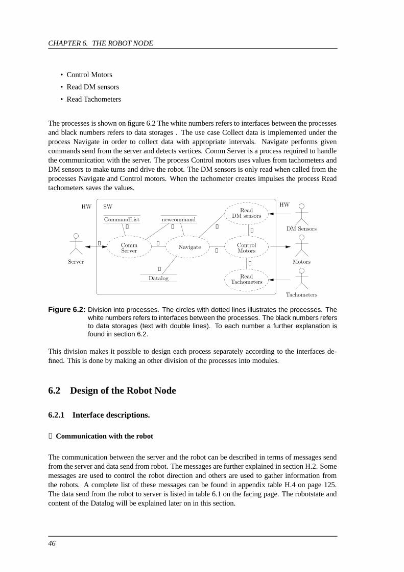
CHAPTER 6. THE ROBOT NODE
• Control Motors
• Read DM sensors
• Read Tachometers
The processes is shown on figure 6.2 The white numbers refers to interfaces between the processesand black numbers refers to data storages . The use case Collect data is implemented under theprocess Navigate in order to collect data with appropriate intervals. Navigate performs givencommands send from the server and detects vertices. Comm Server is a process required to handlethe communication with the server. The process Control motors uses values from tachometers andDM sensors to make turns and drive the robot. The DM sensors is only read when called from theprocesses Navigate and Control motors. When the tachometer creates impulses the process Readtachometers saves the values.
Navigate
HW
➎
➍➋➇
➈Server
➆
➀
➅
➂
HW SW
ServerComm Control
Motors
ReadDM sensors
Motors
TachometersRead
Tachometers
DM Sensors
Datalog
CommandList newcommand
Figure 6.2: Division into processes. The circles with dotted lines illustrates the processes. Thewhite numbers refers to interfaces between the processes. The black numbers refersto data storages (text with double lines). To each number a further explanation isfound in section 6.2.
This division makes it possible to design each process separately according to the interfaces de-fined. This is done by making an other division of the processes into modules.
6.2 Design of the Robot Node
6.2.1 Interface descriptions.
➀ Communication with the robot
The communication between the server and the robot can be described in terms of messages sendfrom the server and data send from robot. The messages are further explained in section H.2. Somemessages are used to control the robot direction and others are used to gather information fromthe robots. A complete list of these messages can be found in appendix table H.4 on page 125.The data send from the robot to server is listed in table 6.1 on the facing page. The robotstate andcontent of the Datalog will be explained later on in this section.
46

6.2. DESIGN OF THE ROBOT NODE
Message from server ping status uploaddata
Robot reply ROBOT_ID ROBOT_ID ROBOT_ID
robotstate Datalog
Table 6.1: The robot replies, when one of the given messages is received. The robot is also ableto upload the Datalog by itself.
➋ CommandList
The commandList contains a queue of commands send from the server.is The list is in order ofexecution and works like a FIFO buffer2. Depending on the messages from the server it is possibleto either add a new command to the list or clear the entire list.
➂ Between Comm Server and Navigate
The interface between the processes Comm Server and Navigate is beside the variable newcom-mand function calls between the processes. The process Navigate fetches the next command inthe commandList by calling a function “getNext”. In process Comm Server, the fetched commandis saved in the variable newcommand. The functions are described in details in appendix 6 onpage 45. The variable robotstate is used to store in which state the robot currently is in. Therobotstate is listed in table 6.2.
status
STAT_WAITING
STAT_DATA_READY
STAT_COMMAND_LIST_EMPTY
STAT_UNABLE_TO_PERFORM
STAT_LOW_BATTERY
STAT_SENSOR_ERROR
STAT_COLLISION_OCCURED
STAT_TURNLEFT
STAT_TURNRIGHT
STAT_TURNAROUND
STAT_DRIVEFORWARD
STAT_UPLOADNG
STAT_VERTEX_FOUND
Table 6.2: The variable robotstate
➍ newcommand
The processes Comm server and Navigate uses the variable newcommand. The variable is writtenby the process Comm Server and read by Navigate.
2First In First Out
47

CHAPTER 6. THE ROBOT NODE
➎ Datalog
The Datalog contains information about which action was performed, the distance traveled andthe possible paths from the vertex found. If the robot makes a left turn, right turn, turns around, ordrives forward a code identifying these actions are stored. When a vertex is found a code indicatingthe type is stored. It is possible to reach the Datalog using functions as “savaData” and “clearData“The possible content of the Datalog is listed in table 6.2.1.
Information Datalog content
ROBOT_ID 1-255
Leftturn 12010
Driveforward 12016
distance xxxxx
Vertex 12047 + bitmask
Table 6.3: Possible values stored in the Datalog. The bitmask indicates in which directions pos-sible paths exits. A complete list of values is found in appendix H.2
➅ Between Navigate and Read DM sensors
The Process Navigate gets the DM sensor values by calling a function “readSensors“ in the processRead DM sensors. It returns the value from each of the sensors, dmsensors1-3: left, center, right.
➆ Between Navigate and Control motors
The process Navigate tells the process Control motor which actions that has to be performed bycalling the functions listed in table 6.4.
Motor Actions Description
driveForward(x) Drives x tacho counts forward.
turnLeft() Makes a 90 to the left
turnRight() Makes a 90 to the right
turnAround() Makes a 180 turn
Table 6.4: The functions to perform turns and driving.
➇ Between Control motors and Read DM sensors
The process Control motors gets the DM sensors values by calling a function “readSensors“. Thereadings are needed to avoid collision.
➈ Between Control motors and Read Tachometers
The process Control motors gets a tachometer value by calling a function “readTacho“.
48

6.2. DESIGN OF THE ROBOT NODE
6.2.2 Division of processes into modules
In this section each process is divided into a number of modules. A module must provide anessential function to the process. A process can exists of one or more modules. If there is morethan one module in a process they are structured hierarchically, implying that a module only canbe reached from the module right above.
The interface to each module is described in terms of entry functions. The modules contains oneor more entry functions and is the only way to enter a module. A specification to each moduleconsists of a description of: input, function, output, parameters and which other functions areinvolved.
The processes are divided into modules as shown on figure 6.3. The modules is shortly describedin the following. The specifications for each module is listed in appendix G.2 on page 113
NavigateComm Server
CommServer
CommandList
newInstructionfetchNext
inComing
uploadData
checkVertex
Check Vertex
detectCollision
CollisionControl
turnAround
turnRight
turnLeft
driveForward
ControlMotors
Control Motors
performCommand
Navigate
clearDataLog
saveData
DataLog
ReadTachos
readTachos
Read Tachometers
ReadSensors
readSensors
Read DM Sensors
Figure 6.3: Division into modules. The dotted lines illustrates the processes. The boxes illus-trates the modules, with their name and entry functions
CommServer The module is responsible for communication with the server, including the han-dling of incoming messages and outgoing data. The incoming messages are interpreted.Messages containing commands are added to the commandList. Messages which requiresan answer are answered. The process is able to interpret incoming messages even if therobot is performing previous given commands.
CommandList This module performs operations on the CommandList. It is able to add commandmessages to the Commandlist and to clear the entire CommandList.
Navigate This module fetches a command from the CommandList and performs the command.If the robot is either searching or driving all three modules Datalog, Control motors andCheckVertex are used. When a vertex is detected the possible directions is stored in theDataLog and the robot uploads the data to server.
49

CHAPTER 6. THE ROBOT NODE
CheckVertex The module detects the possible directions in a maze vertex. It uses the processRead Sensors to detect and determine the the possible paths from the vertex.
DataLog This module manages data about the maze structure. It stores information about theperformed actions, the distance traveled and possible paths from the vertex found.
ControlMotors This module facilitates simple commands to turn and move the robot. The pro-cess uses feedback from Tachometers to remain on a straight course and make turns.
CollisionControl This module detects collisions by monitoring the values from all DM sensors.If the robot gets too close to walls the module performs a correction. If its not applicable tomake correction an error will be raised.
ReadSensors This module multiplexes between the DM sensors and returns the values read.
ReadTachos This module reads a counter value changed by Tachometers. The function is avail-able from the RCX 2.0 operating system.
6.3 Implementation of the Robot node
The software developed to the RCX unit controlling the robots is implemented in the program-ming language NQC. The implementation implies detailed descriptions of the entry functions andpseudo code for every process. All is listed in appendix G.2 on page 113. The source code for theprogram is added on the enclosed CD [CD-ROM 2003].
6.4 Test of the Robot node
According to the SPD method testing a system must be done systematically in order to discovereven the smallest misbehavior of a system. A test of each modules ought to be performed sepa-rately. When all modules forming a process is tested the process can be tested on its own. Then allprocesses can be assembled to the entire system and tested as a whole.
In order to make the entire system operational, it requires that the robots are able to detect vertices,avoid colliding with walls and receive and send the right data. This is considered the main successcriteria for the robots involved in this project.
Such a test at a system level was performed in appendix IV.1 on page 147. It was concluded that arobot was able to detect the possible types of vertices in the maze. The test also showed a reliablerobot searching the maze several times during a half an hour. The performance of the robots,turning and traveling speed and response time, are not essentially to this project and has for thatreason not been tested.
50

Acceptance test 7The following tests are carried out as specified in the acceptance test specification in Test report V.The tests are enumerated for reference purposes. The test design allows only a positive or anegative outcome, but a comment is attached to the individual tests in order to specify exactlywhat the test showed.
• Test date: 15. Dec. ’03
• The entire system
Testemner Nr. Test Ok Remark
Use-case test 1 User authentication No user authentication is im-plemented. Only one user isable to use the program at atime.
2 Start/stop search A search can be started andstopped
3 Change search area It’s not possible to changethe area to be searched withthe current software imple-mentation
4 Display map The client software is able toshow a graphical representa-tion of the map.
5 Zoom on map The map is possible to viewat four different zoom levels.
6 Measure distance on map It is not possible to mea-sure the distance in metersbetween two points, but thisfeature is assumed to be easyto implement.
7 Choose details It is possible to toggle thedisplay of robots on and off.
8 Save map This feature is not imple-mented
9 Print map This feature is not imple-mented
10 Evacuate robots A signal from the clientis generated but not furtherhandled on the server.
System 11 Robot activity The robots are able to
51

CHAPTER 7. ACCEPTANCE TEST
performance navigate in the maze.
12 Update of map The map is updated corre-sponding to the data col-lected by a robot.
13 Collision with walls and other objects The robots are able avoidwalls and objects. How-ever they are not able to dis-tinguish walls from anotherrobot.
14 Cooperation of the robots Because the vertices discov-ered are not interpolated tothe ones already found, thecollected information is notshared. Thus a vertex foundby one robot may be discov-ered as a second vertex byanother.
15 Comparing search time This test could not be per-formed because the robotsare not able to cooperateproperly.
16 Change of search focus This is not implemented.
Table 7.1: Acceptance test results. A indicates that the result was asexpected, and that the system acts as specified. A indicates that the testrevealed a flaw or faults in the system.
52

Conclusion 8This section summarizes the objectives of the project, and the designed system is evaluated withrespect to the requirements that was defined in terms of use-cases in section 2.2. This is supple-mented by emphasizing the main results of the design of the three nodes. The evaluation of theachieved results forms the background for considerations about how the current system could bebrought closer to a final design. Finally an overall conclusion is made.
The chosen project proposal involved construction of two robots using the LEGO mindstormsbuilding kit. The objective of these robots were to search a predefined maze utilizing varioussensors to detect walls and other obstacles. The efforts of the robots was to be coordinated inorder to achieve a faster search. Based upon an introductory analysis of the problem area, aproblem of concern was formulated. A system containing one or more clients connecting to aserver facilitating the control of multiple robots was defined. The robots were equipped withdistance measuring sensors in order to detect the distance to the walls in the maze. The casedriven method was used for defining the demands of a prototype of a search system. Based on theachieved results it is to be concluded whether the designed prototype meets the requirements ornot.
The foundation of this evaluation is the acceptance test performed on the system as a whole. Theresults of the test is referred in section 7.
8.0.1 Test of the Nodes
Various tests was performed on the three nodes in order to validate those before performing theacceptance test of the system. As described in chapters 4 and 5 the design of the control systemis not fully implemented. Two limitations was made due to lack of time, as described below.
The Search Algorithm
Due to lack of time it was necessary to leave parts of the planned implementation out of thedesign of this prototype. According to the focus of the project defined in the system definition, seesection 1.3 on page 3, it was chosen to implement a very simple search algorithm. This algorithmdoes not provide the features necessary to facilitate directing the robots to a certain point in themaze. Whether this is the start point or a point chosen by the operator. Furthermore vertices arenot reserved to the individual robots driving towards it. This implies that a situation could occurwhere two robots drives towards the same point. A collision is however not likely to occur sincethe robot does not differ between walls and other robots.
53

CHAPTER 8. CONCLUSION
The Network Communication
The communication between client and server is not implemented as a network connection, thatis the two applications are in this prototype run on the same computer. The communication ishowever designed in a manner that allows implementing the network connection with a minimalamount of restructuring of the software. See section 4.3.1 on page 35.
8.0.2 Acceptance test
Bearing in mind the limitations in the design as described above an acceptance test was performedto verify which of the requirements defined in the requirement analysis were met by the system.The results of the test is documented in section 7. The use-cases affected by the limitations de-scribed above was not tested. The test was performed using only one robot due to the limitedsearch algorithm.
It was concluded that it was possible to start a search according to the specifications. The robotswere able to detect the walls in the maze and avoid colliding with them. A robot collects the dataand is able to transfer it according to the specifications, see section 6.4 on page 50. The map wasgenerated in the user interface according to the traveled path of the robot. It was possible to scalethe map in the user interface, and hide/show details.
8.0.3 Further Development and Enhancements of the System
The achieved result did not meet all the requirements from the requirement analysis. Thus someimprovements are necessary to complete the intended design. A major improvement would beimplementation of a more advanced search algorithm facilitating the navigation of more than onerobot in the maze. By implementing this it would be possible to test whether the system as assumedis able to handle multiple robots, i.e. collecting data and displaying it in the GUI. This searchalgorithm should also facilitate the necessary functionality for evacuating the robots and changingthe primary search area. This should allow the rest of the system in the current form to meetthe requirements for the Evacuate Robots use-case. Additional functionality could also be addedin order to implement the other remaining use-cases, see section 7. As previously mentioned aminimal amount of restructuring is required for implementing the network connection betweenserver and client.
8.0.4 Overall Conclusion
It can be concluded that the research has resulted in the required learning process as prescribedin the semester regulative. The full implementation of the intended design showed to be too timeconsuming compared to the time and resources available for the project. The designed system withthe degree of implementation achieved is considered as a valid solution to the project proposal.
54

Bibliography
Baun, Dave. 2003.NQC programmers guide v. 2.5 a4. University of Dortmund.@ http://ls12-www.cs.uni-dortmund.de/edu/ES/NQC_Guide.pdf
CD-ROM. 2003.Appendix CD-Rom.Enclosed on CD-ROM.
Douglass, Bruce Powell. 1999.Real-Time UML.2. edition Addison Wesley.
Eriksson, Hans-Erik & Magnus Penker. 1998.UML Toolkit. John Wiley & Sons, Inc.ISBN: 0-471-19161-2
[email protected]. 2003.Sensors basics. [email protected].@ http://www.plazaearth.com/usr/gasperi/lego.htm
Hayes, Patrick. 2003.RoboCup Starter Kit. DTU.@ http://fuzzy.iau.dtu.dk/download/lego6.pdf
Hurbain, Philippe. 2003.Legoo 9V Technic Motors compared characteristics. Philippe Hurbain.@ http://www.philohome.com/motors/motorcomp.htm
Kreyszig, Erwin. 1999.Advanced Engineering Mathematics.8. editionPeter Janzow.ISBN: 0-471-15496-2
LEGO. 2003. LEGO MINDSTORMS SDK 2.0.@ http://mindstorms.lego.com/sdk2/default.asp
Microsystems, Sun. 2003a.JAVA 2 Platform Std. Ed. v1.4.2. Sun Microsystems.@ http://java.sun.com/j2se/1.4.2/docs/api/
55

BIBLIOGRAPHY
Microsystems, Sun. 2003b.JAVA Remote Method Invocation. Sun Microsystems.@ http://java.sun.com/marketing/collateral/rmi_ds.html
Microsystems, Sun. 2003c.Java Technology. Sun Microsystems.@ http://java.sun.com/
Nelson, Russell. 2003.LEGO MINDSTORMS Internals. Russell Nelson.@ http://www.crynwr.com/lego-robotics/
Proudfoot, Kekoa. 2003.RCX Internals. Kekoa Proudfoot.@ http://graphics.stanford.edu/%7Ekekoa/rcx/
Sharp. 20. nov 2003. General Purpose Type Distance Measuring Sensors.@ http://sharp-world.com/products/device/lineup/data/pdf/datasheet/gp2d12_e.pdf
Sørensen, Stephen Biering, Finn Overgaard Hansen, Susanne Klim & Preben Thalund Madsen.2002.Håndbog i Struktureret ProgramUdvikling. Vol. 110. editionIngeniøren|Bøger.ISBN: 87-571-1046-8
56

Methods AIn this appendix methods used in the development of the system will be described.
It is described which parts of the methods we use and which parts we have redefined.Furthermore we will look into the figures used and their respective syntax.
A.1 Strategy
An overall strategy is necessary in order to achieve a structured working process. The strategy ofthis project is based on a method called Structured Programming Development (SPD) [Sørensenet al. 2002]. The goal of this method is to organize the development of a product and to ensurethorough and satisfactory documentation. The process of SPD is as follows:
1. Analysis
2. System requirements
3. Design
4. Implementation
5. Test
6. Validation
SPD emphasizes the importance of choosing a more specific method since it works as a “shell”.We use SPD as a foundation of this project. SPD recommends using a template for the systemrequirements to ensure that all possible demands are identified.
The inner structure of this project will be attacked from an object oriented angle ([Eriksson &Penker 1998] and [Douglass 1999]). This development can be divided into three steps:
1. Object oriented analysis which is mainly concerned with finding out how classes and ob-jects are related to one another.
2. Object oriented design here technical solutions based on the analysis are found.
3. Object oriented programming is the implementation phase.
We use the V-model introduced in SPD, which simply divides the system development in frag-ments. At the top level requirements are made to the system and these are tested in an acceptancetest. The requirements are divided in processes and these are tested as well. Each process aredivided in modules which are tested as well. Instead of using the terminology from SPD we in-troduce the notion from Object Oriented programming, which suits our needs better.1 This is
1The modified V-model is self-invented.
57

APPENDIX A. METHODS
depicted in figure A.1. At top level a requirement analysis is made, these requirements will betested in an acceptance test. The nodes found in the requirements analysis will all be analysed andtested seperately in a socalled Nodal test. Each nodal analysis ends with multiple classes thesewill be designed in the next level, and tested in a Class test. At the bbottom level the actual writingof classes takes place.
-Server
-Robot
Class test
Acceptance
test
Requirement
Analysis
-Use cases -Use cases
Class
Implementation
Node analysis
-Client
-Server
-Robot
Node test
-Client
Class design
Figure A.1: Modified V-model
The system will be developed according to an iterative and incremental development method Thisapproach implies that parts of the system is workable in relative short time.
There are different approaches to solve a given problem using object oriented programming. Inthis project the approach chosen is the so-called Case-driven method. Instead of taking the stepsfrom analysis to programming in one big lump this method divides the processes in many smallerpieces.
The advantage using this approach is that the system is partially running in relative short time,whereas executable code when choosing the other approach may first show near the end of theproject.
The Case-driven method is characterized by the system developer focusing on the user of thesystem - which is the dynamic part. Instead of focusing on the static part - the problem domain.
The documentation of the software development will be written in a language called Unified Mod-eling Language (UML). This language is specifically designed for documenting object orientedsystem development, which suits this project.
Throughout this report diagrams and symbols are taken directly from the UML standard.
58

A.2. UML DIAGRAMS
A.2 UML diagrams
Th Unified Modeling Language is not a method nor a development process, UML is semantics andconsists some of the following diagrams:
Use case diagram consists of actors, use cases, and connection lines as depicted in figure A.2.
”Uses”
”Interface”
”Actor1”
”System1”
”Use case1”
”System2”
”Use case2”
”Actor2”
”Connection2””Connection1”
Figure A.2: Use case diagram containing two actors, and two usecases. The use-cases aresituated in two different systems where use-case1 uses use-case2. The diagramalso indicates that there is an interface between these two systems.
Class diagrams show the structure of the system in terms of classes and objects. Class diagramsshows how objects and classes relate to each other. This is depicted in figure A.3.
Operation2
Operation1
Class1 name
Attribute1
Attribute2
Operation1
Operation2
”Aggregates” ”Interfaces”
Attribute2
Class2 name
Attribute1
Attribute2
Operation1
Operation2
IFClass1 name
Attribute1
Figure A.3: Class diagram containing three classes. Each class has attributes and operations.The diamond indicates an aggregation whereas the hollow arrow indicates an inter-face. All interface classes are named with IF as prefix.
State diagrams capture the life cycle of either one object or a system containing several objectsin terms of the different states they can assume. The transitions between states happens,whenever an event occurs. Figure A.4 shows a simple example of a state diagram. The de-piction of the individual states is divided into three compartments. The upper compartmentcontains the name of the state, while the second, optional, compartment contains eventualattributes used within the state. The third compartment contains the activities that happensinside the state.
The UML language defines four kinds of events. The Guard Conditions are boolean expres-sions and a transition can occur only when these are true. Explicit Signals and Method Callsfrom other objects, or in the latter the object itself, are both covered by the term message.The Passage of a certain amount of time can also be an event, e.g. a time-out.
Sequence diagram shows interactions between objects over time. This is depicted in figure A.5.
Collaboration diagram is an extended sequence diagram that shows objects and their relation-ships.
Activity diagram is an extended flow diagram with asynchronous transitions. Figure A.6
59

APPENDIX A. METHODS
Start
State1 State2
State3
transition1
transition3
transition4
signal
transition2
State name
State variables
Activities
Figure A.4:A state diagram sequence con-taining three states. The dot in-dicates the start point, while thebulls eye is the end point. Thearrow with the hollow triangle in-dicates a signal from another ob-ject that initiates a transition. Thethree compartments that definesthe state is shown to the right.
operation2();
:Object2
operation1();
operation2();
:Object1
Figure A.5: Sequence diagram in-volving two objects.:Object1 calls amethod, “operation1” in:Object2.
! "#
$
%&(' )+* !,
-
%. .
/ 0
12 3
%&(' )4* 5
6 78* ' 09 8* ' 0
: 2;'
Figure A.6: Activity diagram explaining different elements used.
60

A.2. UML DIAGRAMS
Deployment diagram shows the physical architecture of the hardware and software componentsof the system. This is depicted in figure A.7.
Node1
Interface
Component2Component1
Node2
Actor1 Actor2
Figure A.7: Deployment diagram containing two nodes. Each node containing a Component. Acircle indicates an interface. Furthermore two actors are connected to the deploy-ment diagram.
61

.

Robot construction BThis appendix describes how the robots are constructed. First the basic topics of the LEGO Mind-storms building kit are covered, followed by a description of how the distance measurement sensorsare placed on the robot. The appendix is completed by the documentation of the mechanical designof the robot.
B.1 LEGO Mindstorms
The building kit consists of regular LEGO bricks, motors, tachometers, RCX unit and an IR-Tower. LEGO offers many other sensors which aren’t used in this project, therefore these shall notbe described. The same applies to LEGO bricks.
Introducing the RCX from Lego
A RCX unit is a programmable brick based on a micro-controller. It’s able tosimultaneously operate three motors, three sensors, and an infrared serial communi-cations interface.
The base system consists of the RCX itself, an infrared transceiver, and a PC. Ad-ditional components, such as motors, sensors, and other building elements are addedto create a functional robot.
“At the core of the RCX is a Hitachi H8 micro-controller with 32K of externalRAM. The micro-controller is used to control three motors, three sensors, and an in-frared serial communications port. An on-chip, 16K ROM contains a driver that is runwhen the RCX is first powered up. The on-chip driver is extended by downloading16K of firmware to the RCX. Both the driver and firmware accept and execute com-mands from the PC through the IR communications port. Additionally, user programsare downloaded to the RCX as byte code and are stored in a 6K region of memory.When instructed to do so, the firmware interprets and executes the byte code of theseprograms.” [Proudfoot 2003].
The RCX is depicted in figure B.1 with different kinds of sensors connected to the sensor inputs.Only tachometers from LEGO are used.
The micro controller used in the RCX is presented in terms of product name, number and specifi-cations in table B.1. The RCX is supplied from 9V (6 × AA batteries).
63
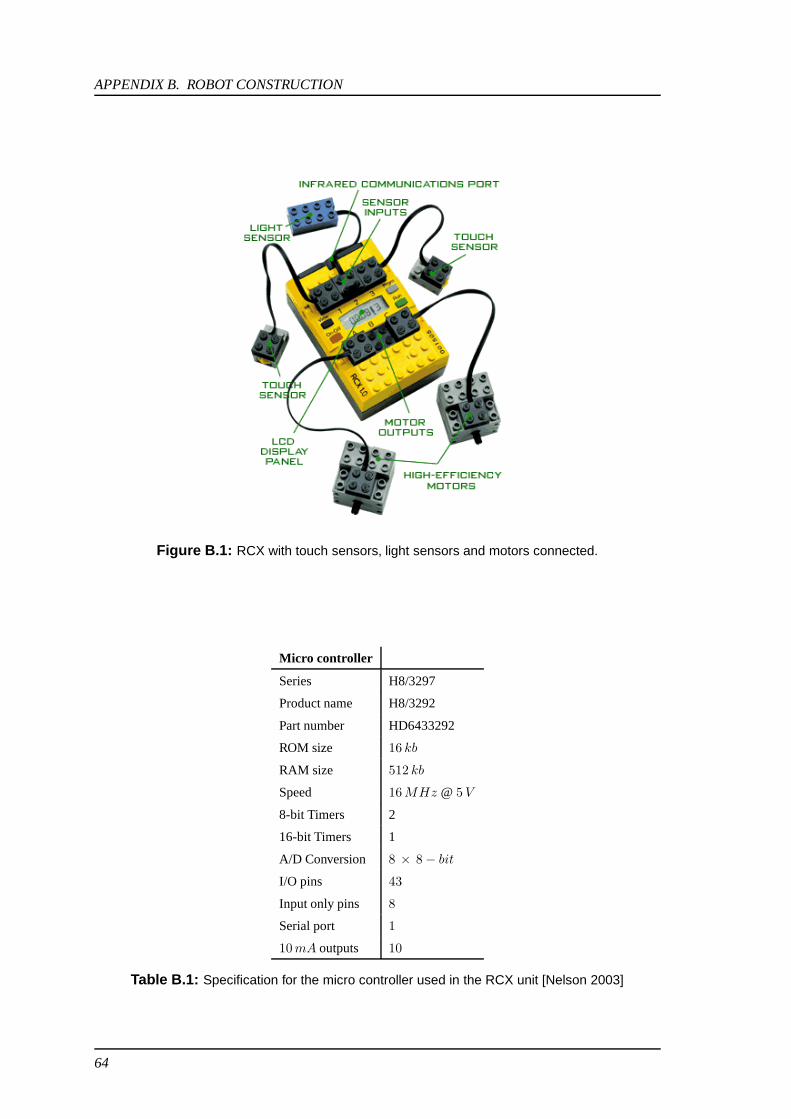
APPENDIX B. ROBOT CONSTRUCTION
Figure B.1: RCX with touch sensors, light sensors and motors connected.
Micro controller
Series H8/3297
Product name H8/3292
Part number HD6433292
ROM size 16 kb
RAM size 512 kb
Speed 16 MHz @ 5 V
8-bit Timers 2
16-bit Timers 1
A/D Conversion 8 × 8− bit
I/O pins 43
Input only pins 8
Serial port 1
10 mA outputs 10
Table B.1: Specification for the micro controller used in the RCX unit [Nelson 2003]
64

B.1. LEGO MINDSTORMS
Sensor inputs
The RCX has 3 independent inputs which is operated in either active (the input supplies power andthen samples the input voltage) or passive mode (the input is sampled). In the latter case the inputis pulled up to 5V with a 10 kΩ resistor. In active mode the RCX uses a 120Ω resistor pullingthe voltage up to about 8V for about 3ms and then looks at the sensor voltage during 0.1ms as ifit was a passive sensor [[email protected] 2003]. The input voltage is converted using a 10 bitA/D (the full-range value is 5V ).
Tachometers
The output from a LEGO tachometer can assume 4 different values: 1.8V , 2.6V , 3.8V , and5.1V . Figure B.2 shows a output sequence for a tachometer with increasing values. Because thesevoltage levels repeat 4 times per revolution, the tachometer achieves a resolution of 360
16= 22, 5 .
From the pattern the RCX can tell in which direction the tachometer is turning.
Figure B.2: Voltage sequence with increasing values [[email protected] 2003].
Motor outputs
The RCX has 3 motor outputs, all bi-directional. From Kekoa Proudfoots work on the internals ofthe RCX, it is found that the motor outputs are the MLX10402 from Melexis11. They are completeH-bridges that can control 12V DC motors at loads up to 500mA. The motor outputs deliver anoutput of 9V , polarity is dependent on the chosen direction. Speed control is done by pulse-widthmodulation (PWM). The motors can be set to run in either direction, be brought to a full stop/holdposition or put in to float (free running) [Hayes 2003].
Motors
Table B.2 on the next page lists the basic characteristics [Hurbain 2003] of the used LEGO motors.
65

APPENDIX B. ROBOT CONSTRUCTION
Motortype 71427
Weight 42 g
Rotation speed (at 9 V ) 360 rpm
No-load current 3, 5 mA
Stalled torque 6 Ncm
Stalled current 360 mA
Table B.2: Motor characteristics
B.2 Analysis of sensor placements
The main goal of the robot involved in this project is to locate obstacles and walls. This requiressome kind of sensors mounted on the robot to collect information as, the robot traverse the searcharea. In the following three possible solutions will be introduced. The sensors introduced in thissection are further explained in appendix C on page 73
B.2.1 Solution 1
In this solution the robot navigates by following a marked line on the floor (see figure B.3). Ob-stacles and walls could be detected when the robot bumps into them. The position of the robot isfound by measuring the number of revolutions of each wheel.
Figure B.3: A robot using light sensors
This solution requires that there is a lot of information stored in the model (maze) which meansthe construction of the robot may be simple. The marked line must cover the whole search area.Thus it’s only possible to navigate in a marked area (model). Any obstacles will be treated as awall.
B.2.2 Solution 2
Another solution could be to mount one or more distance measuring sensors on the robot.
66

B.3. PLACING THE SENSORS
Robot with one distance measuring sensor
The search area is scanned in a circular pattern by rotating a robot equipped with a distance sensor(see figure B.4). The angle could be calculated by knowing the position of each wheel. Positioningof the robot could be done either by the revolutions of the wheels or by readings from the distancemeasuring sensor.
Figure B.4: A robot using one distance sensor
This solution provides a better image of the robots surroundings due to the input from the distancesensor. If the robot follows a marked line you don’t get the contour of the surrounding walls. It isalso possible to navigate better outside the constructed maze without any modifications as long asthe objects can be detected (they must be of a certain size).
The measurements consist of a distance and an angle thus their precision depends on the accuracyof the distance sensor and the measurement of wheel positioning and the wheelbase.
Robot with multiple distance measuring sensors
By placing several distance sensors in an array you get more points measured without turningthe robot (see figure B.5 on the next page). This solution could also determine the position bymeasuring the revolutions of the wheels or from the distance measuring sensors.
Obstacles need to be of a certain size (depending on the angle between adjacent sensors and thedistance to the obstacle) in order to be detected without turning the robot.
B.3 Placing the sensors
We choose to further analyze “Robot with multiple distance measuring sensors” because the searchis potentially faster than the solution with one distance sensor. It is assumed that turning the robotis slower than switching between sensors. Furthermore it’s a more flexible solution than “Robotwith light sensor” which only can be used in a prepared search area and thus not useful in a real
67

APPENDIX B. ROBOT CONSTRUCTION
Figure B.5: A robot using several distance sensors
world application. The number of sensors and their placement will be discussed in the followingsection
B.3.1 How many sensors?
The first question that arises is how many sensors are needed? At least one is needed to detectpossible walls and obstacles in front of the robot and two more to detect walls on each side of therobot. These could also be used to keep the robot driving parallel to the walls. It’s not necessary tomeasure the distance to the walls and obstacles behind the robot because that area has already beencovered. More sensors would cover the area better, but because the maze is simple it is sufficientwith three sensors. A solution with one sensor pointing straight forward to detect any walls andobstacles in front of the robot and one to each side as well is selected.
Because the distance measuring sensors have a limited range and resolution we decide to determinethe position of the robot by measuring the revolutions of the wheels. This is done by connecting atachometer (appendix B.1 on page 65) to the transmission on each wheel.
As the RCX is limited to 3 input and 3 output some switching circuit must be constructed in orderto feed the RCX with inputs from 2 tachometers and 3 distance measuring sensors.
B.3.2 Angle
The sensors pointing to each side could be placed perpendicular to the direction the robot is mov-ing. This however means that the robot only measures a short distance most of the time. Onlywhen it hits an intersection the measurements would be different.
If the sensors are mounted at an angle of ±45 the front would be better covered and the mea-surement to each side is done ahead of the robot (see figure B.6 on the next page). As the angle αapproaches 0 (pointing forward) the front will be better covered but at the expense of detecting theside walls. When the angle approaches 90 the front isn’t covered, which suggest a compromiseat a 45 angle.
68

B.4. PHYSICAL DESIGN OF ROBOT
Figure B.6: The robot with the positions of the sensors encountering an object
B.3.3 Conclusion
A total of 5 sensors are needed: 2 tachometers used for calculating the position, and 3 distancemeasuring sensors to detect walls (as depicted in figure B.6). The distance measuring sensors arepositioned with a 45 to each other in order to cover the front with all three sensors and the sideswith a sensor on each side. Some electronic circuit must be constructed in order to interface the 5needed sensor inputs to the RCX. A description of the constructing of such a circuit can be foundin appendix C.2 on page 75.
B.4 Physical design of robot
This section contains a description of the physical design of the robots and the considerations uponthe design
Based on the fact that a robot should be able to navigate around the maze mentioned in chapter D onpage 77, the robots should be quite small. The shortest distance between walls in the maze is28 cm.
The width and length of the robot is designed to enable the robot to make a 180 turn in themaze. If a robot is 15.7 cm times 16.0 cm this demand is kept. See details and dimensions onfigure B.7 on the next page.
B.4.1 Driving and turning the robot
To make the robot pivot 180 about its center requires that each wheel is turning at exactly thesame speed (but opposite velocity). It’s presumed that this will not be possible. Instead a 180
turn is divided in two parts. Then only one motor needs to run at a time. Figure B.4.1 on page 71shows wheel movement for turning a robot.
The transmission between a motor and a wheel uses cogwheels, 40 cogs on the drive-wheel and
69

APPENDIX B. ROBOT CONSTRUCTION
! #" %$! #" %$
&')(*+-, %$
. %/#0213*4*5 ,
6 .87
9;:#<13 %=>*4"*$?,
@A13*4*5 ,
9CB3$?+3D +-/#0'1-**5
E
F?6G<4 %=H=IB3+-D <:"D %+
Figure B.7: A detailed drawing of the robots
8 cogs on the motor axle. This makes a ratio of 40/8 = 5. With a motor rotating 360 rpm (fromtable B.2 on page 66) makes the robot max speed, 0, 31 m
s.
To prevent the robot from turning over and making it turn more easily a small independent turningwheel was placed at the rear end of the robot. The RCX unit is placed as close to the front wheelsas possible, to keep the robot well balanced.
B.4.2 Traveled distance and path of the robots
To measure the distance and path traveled by a robot a set of tachometers (see section B.1 onpage 65) were connected directly on to the cogwheel attached to the driving wheel. Using thesame size of cogwheel on the motor and tachometers, made it possible to determine the rotationof the motor. One round on a motor equals one round on a tachometer (which corresponds to 16impulses, appendix B.1 section B.1).
B.4.3 Measuring distance to walls
In order to measure the distance to walls 3 distance measurement sensors was placed pointing in aforward direction on the robot.
Placing the sensors in a 45 angle required that the sensors were able to detect objects facing itfrom this angle. A test confirms this, see test report I.1.4 on page 132.
70

B.4. PHYSICAL DESIGN OF ROBOT
(a) A robot pointing in the di-rection of the arrow
(b) Robot turned 90 clock-
wise(c) Robot turned 180
Figure B.8: Scenario for turning the robots
Measurement of Index Value
Distance track to track Td 14.4 cm
Circumference of wheel Wc 25.6 cm
Distance moved D ± 0.32 cm (Calculated)
Angle moved α ± 1.27 (Calculated)
Table B.3:
The sensors does not provide valid measurements when objects are closer than 10 cm [Sharp 20.nov 2003]. By displacing a sensor mounted sideways to the opposite side of a robot makes itpossible to drive closer to walls before the distance from the sensor is below 10 cm.
B.4.4 Navigation accuracy
From the robot construction it’s possible to make some predictions about the accuracy for navigat-ing the robot.
The tachometer makes 16 impulses per turn. Based upon this its possible to determine how muchthe wheels can move without getting change in input from tachometers. The fault in distancealso generates a fault on the angle when turning the robot. Knowledge about this is relevant fordetermining the accurate robot position in the maze. The next formulas calculates this maximumdistance and angle. In table B.3 is the needed factors and results.
± D =Wc
tacho · gear=
25, 6
16 · 5= ± 0.32 cm
± α =D
2π · Td
· 360 =0.32
2π · 14.4· 360 = ± 1.27
71

APPENDIX B. ROBOT CONSTRUCTION
B.5 Conclusion
In this appendix a construction of the robots were analyzed. Two robots were made using LEGOMindstorms Building kits to suit the needs when searching the maze described in appendix D.
Using these robots in other environments than the specified maze may lead to incorrect results.The distance measurement sensors and their scope are described in appendix C.
72

Distance Measuring sensor CIn this appendix a specific sensor device is chosen, and the relevant properties of this device aredetermined. As concluded in section B.3.3 on page 69 three sensors are needed per robot formeasuring distances to objects in the maze e.g walls. In section C.1.1 relevant information fromthe data sheet is extracted. To cover the remaining issues a number of tests is performed on thedevices, appendix I.1 on page 129. Upon summarizing the results from these tests in section C.1.2a qualitative assessment is made regarding the chosen sensor type. Finally it is explained howthese sensors are interfaced to a RCX unit.
C.1 The GP2D12 sensor
The GP2D12 use the triangulation principle to compute the distance to objects in the field of view.The basic idea of this principle is this: A pulse of IR light is emitted by the emitter. This lighttravels out in the field of view, and either hits an object or just keeps on going. If the light reflectson an object, the relected light is detected by a CCD1 array. A triangle is created between the pointof reflection, the emitter, and the detector. The distance is then determined from the geometricalproperties of this triangle.[Sharp 20. nov 2003]
C.1.1 Information from datasheet
According to the datasheet the sensor has a detecting range of 10 − 80 cm [Sharp 20. nov 2003].The input to output relation is graphed in [Sharp 20. nov 2003][Figure 6]. It shows that theoutput follows an approximate hyperbolic curve in a closed region (8 − 80 cm). The distancemust not drop below 8 cm in which case a given voltage cannot be uniquely mapped to a distance.To represent the distances in the field of view from L = 10 cm to L = 80 cm a voltage outputof: 1, 75V , typ: 2, 0V and max: 2, 25V is available. This possible deviation of 0, 5V betweenindividual sensors establish the necessity for performing tests on the individual sensors.
Another parameter of interest is how the sensor respond to changes in the reflectivity. This isdepicted in [Sharp 20. nov 2003][Figure 6], which graphs “The output voltage vs the distanceto reflective object” at different reflectivities. It is observed that a change from 90% to 18% inreflectivity has very little effect.
It can be observed from figure 8 in the data sheet, that the shape of the emitted IR light allowsreliable detection within a deviation of 3 cm from a straight line from the emitter to an objectin 80 cm distance. When the distance decreases so does the width of the IR-light beam, which
1Charge Coupled Device
73

APPENDIX C. DISTANCE MEASURING SENSOR
implies that objects much be directly in front of the sensor at small distances (10− 30 cm) to havea reliably output [Sharp 20. nov 2003][Figure 8].
[Sharp 20. nov 2003][Figure 7] shows how the ambient temperature affects the voltage output.Because the sensors are only used indoor, the voltage output will only differ slightly, approximately±20mV at 25 ± 10.
As the sensor features a signal processing circuit some time elapses before the output voltage isaffected. A measurement takes: 38, 3 ± 9, 6ms to complete plus an additional “End of measure-ment to output valid: 5, 0ms,max”. An average measurement frequency with output valid is thenfavr = 1
38,3 ms+5,0 ms= 23, 1Hz.
C.1.2 Unknown characteristics and measurements
The information retrieved from the data sheet leaves two questions of relevance to this applicationunanswered:
• What is the deviation between individual devices of this type?
• How does a change in the angle of attack influence the output?
The above questions have been examined by perfoming tests on the objects, see section I.1 onpage 129. The following is a summary of the obtained results.
The measurements shows that the sensors does not respond equally to an object placed in a givendistance from the sensor. Thus the response from each individual sensor must be applied when adistance is to be calculated from the sensor output voltage. By using a polynomium obtained byperforming linear regression on the data this approximation can be fairly accurate.
Assuming the angle of attack doesn’t change more than 10 relative, the uncertainty will be nomore than about ± 2 cm between 10 − 60 cm for all 6 sensors. It is estimated that a accuracy of±5 cm can be obtained when the distance is higher than 60 cm.
C.1.3 Assessment of the obtained accuracy
Assuming that the angle from the sensors to the walls doesn’t change more than 10 the uncer-tainty is limited to ±2 cm before sampling2 . Furthermore an ADC always introduce quantizationerrors, typical below± 1
2LSB3. The technical data of the RCX internal ADC has not been available
but is assumed that an error of ± 1
2LSB responding to a voltage of 5
210 = 0, 005V is a reasonableestimate. This does not affect the overall accuracy significantly.
Because the 10 bit ADC samples linear from 0−5V (the samples are equally spaced) and the curveof “output voltage versus distance” is hyperbolic, the shorter distances will be more represented.Figure C.1 on the next page shows a stem plot, and how the lines at shorter distances have a higherdensity than at longer distances.
2The obtained approximation to the individual sensor characteristics was achieved by linear regression and theresult was a 6
th degree polynomial with a S-squared value of ≈ 0, 11. This inaccuracy is very small and is therefor notconsidered when evaluating the overall accuracy of the distance representation.
3Least Significant Bit
74

C.2. INTERFACING THE DM SENSOR WITH THE RCX UNIT
0 10 20 30 40 50 60 70 800
0.5
1
1.5
2
2.5
Distance [cm]
Ana
log
outp
ut v
olta
ge
Figure C.1: Output voltage versus distance at discrete voltages. The step size is 5 V
210 ≈ 5 mV
C.2 Interfacing the DM sensor with the RCX unit
The output of the DM sensors must be represented as binary values on the RCX. This requires anappropriate interface to the RCX and an analog to digital conversion. The inputs of the RCX hasa 10 bit ADC (Analog to Digital Converter) with a 10 kΩ pull-up resistor to 5V . Only 1 input onthe RCX is available since two inputs are used for tachometers.
To interface the three distance measuring sensor to a single input on the RCX a switching circuitis necessary.
The purpose of this circuit is to switch between the 3 DM sensors by using only one input butalso a output of the RCX. The output signal is used as selector signal which is described laterin this section. The actually switching is done by a 4-channel analog multiplexer/demultiplexer(74HC4052). In order to determine which sensor that has previously been connected, and thuswhich sensor is to be connected next, a reference signal is introduced. This signal is at 5V levelwhich separates it from the sensor inputs that have max values below 3V .[Sharp 20. nov 2003]This signal is applied by connecting the supply voltage to the X3 input on the multiplexer, U1 onfigure C.2. When a 5V signal is asserted on the RCX sensor input it is known that the sensor tobe read next is sensor 1.
To switch between 4 signals a 2-bit digital signal is required as input to the multiplexer. This signalis generated by connecting one the RCX outputs to a counter, U2 on figure C.2. signal. The outputof the RCX delivers 8V and the input of the counter is limited to 5V . To handle this R1 and R2forms a voltage divider with a voltage drop of 5V across R2. The rectifier formed by D1, D2, D3and D4 is necessary because the RCX can deliver ±8V . U3 and the capacitor, C1, supplies thecircuit with a constant voltage of 5V . The last component is a operational amplifier (U4) which isused as a buffer to lower the impedance as needed for the RCX.
75

APPENDIX C. DISTANCE MEASURING SENSOR
5
5
4
4
3
3
2
2
1
1
D D
C C
B B
A A
<Doc> <RevCode>
<Title>
A
1 1Sunday, November 16, 2003
Title
Size Document Number Rev
Date: Sheet of
motor1
motor2
to input on RCX
to input on RCX
sensor3sensor2sensor1 supply
supply
-
+
U4
TLC2713
26
75481
D3
U174HC4052
12141511
1524
6
109
13
3
167
X0X1X2X3
Y0Y1Y2Y3
EN
AB
X
Y
VDDVEE
U3
LM7805/TO1
3
2 VIN
GN
DVOUT
D4
C11000u
R13k D1
R25k
D2
U2 74HC93141
1298
11 23
CLKACLKB
QAQBQCQD R01
R02
Figure C.2: Schematic of the multiplexer circuit used to interface 3 distance measuring sensorsto a RCX
76

Exploring the Maze DThis appendix covers the definition of a mathematical representation of the maze, see figure D.1.
This representation is utilized in the design of the software responsible for controlling the robots.After the presentation of the mathematical theories a set of rules, that defines the method forsearching the maze, are listed and described
200 cm
28 cm
200 cm
Figure D.1:The maze used in theproject. The white areais where the robots areable to drive whereasthe grey area isn’t.
The task is to obtain a representation of this exact topology by searching the area with two robots,opposed to the above where the representation is achieved in one step using a camera. The designof the algorithm must facilitate for a least two robots to share this task and to make the searchfaster.
The terminology used to describe the maze in the following is inherited from the mathematicaltheories of Graphs and Combinatorial optimization. The theory of graphs are applicable whendescribing the travel through a maze. The theories of combinatorial optimization are mainly con-cerned with traveling already known mazes in different ways depending of the desired kind ofoptimization, e.g the shortest path between two points. This is not relevant in the situation wherethe possible paths are to be determined in an unknown maze. It can however be necessary to directa robot through known area to some point in the maze.
D.0.1 Mathematical Theory
The following summary of the concepts behind graphs are taken from [Kreyszig 1999]. It ischosen to consider the maze as a graph consisting of connected lines of undefined width. Themathematical definition of a graph is as follows:
77

APPENDIX D. EXPLORING THE MAZE
A graph G consists of two finite sets(sets having finitely many elements), a set V ofpoints, called vertices, and a set E of connecting lines, called edges, such that eachedge connects two vertices, called the endpoints of the edge.
In order to collect the desired data, the robots must walk the graph, i.e. the maze. The graph
5 4
1 2
3
Figure D.2: A simple graph which it is possible to make a walk, trail, path or cycle
depicted in figure D.2 can be traversed in the following ways:
Walk No restrictions are required and a walk could in this case be 1-4-5-4
Trail The edges must be traversed at most once e.g. 5-4-3-2-1-4
Path The vertices must be visited at most once e.g 1-2-3-4-5
Cycle Is defined as a closed path e.g. 1-2-3-4-1
The success criteria is to explore the complete topology of the maze as fast as possible. In the mazedepicted on figure D.1 the topology can be described as the positions of all the vertices. In orderto suffice for searching a maze of arbitrary complexity and dimensions it is however necessary totraverse all the edges at least once. The ideal scenario is obivously if all the edges are traversed atmost(and at least) once resulting in a trail as described above. It is not possible to obtain this resultanalytically since this would require knowledge of the maze. The trail can however serve as a toolwhen evaluating the performance of the implemented search method.
In the situation where a robot is to be directed from one vertex to another traversing a known areaof the maze it is necessary to calculate a path. This path should be the shortest possible, whichcan be achieved using an mathematical algorithm, such as Moore’s algorithm. This algorithm isbased upon the Breadth First Search principle, where the algorithm visits all adjacent1 vertices ofa vertex reached [Kreyszig 1999, page 1016].
D.1 The Search Method
As concluded in previous it is not possible to implement an analytical search algorithm. The searchwill therefore consist of a number of rules. An optimization could then be achieved by evaluatingthe result of different sets of rules. In this project the following set of rules is applied and evaluated.It is implicit in the following that the robots requests new direction at every vertex.
1Two vertices are considered adjacent if they are connected by an edge.
78

D.1. THE SEARCH METHOD
1. The robots are given a priority.
2. Before starting the search the two robots are placed in the maze at some starting point. Theyare placed facing opposite directions. A fictive vertex is registered in front of each robot.
3. The robots have different driving preferences. In the case with two robots Robot 1 does oneof the following when arriving at a vertex connected with yet unknown edges:
(a) Drives Right if possible.
(b) Drives Straight ahead if 3a not possible.
(c) Drives left if neither 3a or 3b is possible.
(d) Turns around if none of the above is applicable.
The second robot does the same except in reversed order, that is first left, then straight and ifthat’s not possible it tries right. The calculation of which of the above is applicable is doneon the server.
4. When a robot arrives at a vertex where all the edges connected to it has already been tra-versed it is given a direction to a vertex elsewhere in the maze that is connected to unknownedges.
5. If two robots during a search arrives at two vertices connecting the same edge the one withthe lowest priority is given a path to another vertex as described in 4.
6. When a robot is assigned an edge the vertex at the other end is reserved until the robot hasvisited the vertex, upon which it is released..
79

.

Client EIn this appendix the design of the Client node is documented in detail. A complete class diagramis introduced and the classes are described. This description consists of a tabular summary of thepublic methods and attributes in the class followed by a more detailed description of the methods.
Classes and Interfaces in the Client node
Figure E.1 depicts all classes, interfaces and their static relations in the Client node.
ToolPanel Menu ClientControl
History IFHistory IFClientControl
SysIO
ViewPanel
ClientComm
Gui
Figure E.1: Full clasdiagram depicting all classes, interfaces and their static relations in theClient node .
E.1 Gui
This is the main class in the client application and it must be run when the client is started. Itbuilds the frame for the main window and starts the client application.
81

APPENDIX E. CLIENT
The Gui class inherits the properties of the javax.swing.JFrame which contains useful meth-ods for building a GUI e.g. construction the main window, menu bars etc.
Gui
- viewPanel : ViewPanel
- toolPanel : ToolPanel
- menu : Menu
- clientControl : ClientControl
- linkClientMap : ClientMap
+ main(argv : String)
+ Gui()
Table E.1: Contents of the Gui class.
main: The main method constructs a new :Gui object, sets the size and position of the windowand starts the application. The parameter argv is an array of command line arguments, itis part of the Java language that the main method must be declared this way, even if noarguments are processed in the function.
Gui: This is the constructor for the class. It creates the main window for the application, set upthe required links between the objects :ViewPanel, :ToolPanel, :ToolPanel, :Menu,:ClientControl and :ClientMap as specified in figure E.1. After creating the objectsthe menu, toolPanel and viewPanel is added to the window.
E.2 ViewPanel
The purpose of this class is to display the map and the command history to the user. The ViewPanelclass inherits the properties of the javax.swing.JPanelwhich contains useful methods for dis-playing GUI components (buttons, graphics etc.) It is specified in 2.6.1 that the map must beupdated approximately once a second. To facilitate this the ViewPanel class starts a thread thatdownloads an updated version of the map from the server approximately once a second. To handleinputs from the mouse when measuring distances on the map the java.awt.event.MouseListenerand java.awt.event.MouseMotionListener interfaces are implemented by this class. To al-low the use of threads the java.lang.Runnable interface is implemented.
ViewPanel: The Constructor sets up a link to the linkClientControl:IFClientControl
object provided as parameter to the constructor.
init: This method sets up link to the :ToolPanel object.
run: This method is needed when implementing the java.lang.Runnable interface. It handlesthe :Thread object mapThread which is at timer that performs the task of updating the mapby getting a new :IFMap object from the server node.
mouseClicked: This method is invoked when the mouse is clicked over the map area. From the:MouseEvent object can be determined where on the map the mouse was clicked.
82

E.3. TOOLPANEL
ViewPanel
+ history : History
- linkToolPanel : ToolPanel
- linkClientControl : IFClientControl
+ ViewPanel(clientControl : IFClientControl)
+ init(toolPanel : ToolPanel)
+ run()
+ mouseMoved(event : MouseEvent)
+ mouseClicked(event : MouseEvent)
Table E.2: Contents of the ViewPanel class.
mouseMoved: This method is part of the java.awt.event.MouseMotionListener inter-face. It is invoked when the mouse is moved over the map area. I this implementationit passes the position of the mouse to the tool panel. In collaboration with data from themouseClicked() method it can there be processed to compute distances on the map.
E.3 ToolPanel
This class creates the tool panel that contains the buttons etc. for controlling the system. TheToolPanel class inherits the properties of the javax.swing.JPanel which contains usefulmethods for displaying GUI components (buttons, graphics etc.) To handle inputs from the buttonsthe java.awt.event.ActionListener interface is implemented by this class.
ToolPanel
- linkHistory : IFHistory
- linkClientControl : IFClientControl
- linkClientMap : IFMap
+ ToolPanel(history : IFHistory, clientControl : IFClientControl, clientMap : IFMap)
+ actionPerformed(event : ActionEvent)
+ setMousePosition(p : Point)
Table E.3: Contents of the ToolPanel class.
ToolPanel: The Constructor set up links to the :IFHistory, :IFClientControl and the :IFMapobjects. It creates all necessary buttons and adds event listeners to them. Keyboard shortcutskeys are set for the buttons if applicable.
actionPerformed: This method is invoked when a button is pressed. It handles all inputs fromthe buttons.
83

APPENDIX E. CLIENT
E.4 Menu
This class builds menu bar. To handle inputs from the menu items the java.awt.event.ActionListenerinterface is implemented by this class.
Menu
+ Menu(history : IFHistory, clientControl : IFClientControl)
+ actionPerformed(event : ActionEvent) + main(argv : String)
Table E.4: Contents of the Menu class.
Menu: The Constructor set up links to the :IFHistory and the :IFClientControl interfaces.It creates the menu bar, menu items and adds listeners to the menu items. Keyboard shortcutskeys are set for the menu items where applicable.
actionPerformed: This method is invoked when a menu item is selected. It handles inputs eitherby performing the required action, or by calling an appropriate method in the :IFClientControlinterface.
E.5 ClientControl
This class handles user input either by performing the requested operation locally or by send-ing an appropriate request to the server. Other objects interact with this class via the interfaceIFClientControl.
ClientControl
- clientComm : ClientComm
- clientMap : IFMap
- sysIO : SysIO
- userID : IFAuth
+ ClientControl()
+ changeSearchArea(active : boolean)
+ evacuateSearch()
+ getClientMap() : IFMap
+ printMap()
+ quit()
+ saveAs()
+ startSearch()
+ stopSearch()
Table E.5: Contents of the ClientControl class.
84

E.6. HISTORY
ClientControl: The constructor creates a :ClienComm object performs user login and retrievesthe map from the server.
startSearch: This method is required when implementing the IFClientControl interface. Itsends a command to server indicating to start the search process.
stopSearch: This method is required when implementing the IFClientControl interface. Itsends a command to server indicating to stop the search process.
evacuateSearch: This method is required when implementing the IFClientControl interface.It sends a command to server indicating to evacuate the robots.
changeSearchArea: This method is required when implementing the IFClientControl inter-face. It sends a command to server indicating to change the primary search-area. The inputparameter active is used for seting the status of the process. When true the user can selectthe primaty search area on the map.
getClientMap: This method is required when implementing the IFClientControl interface.It retrieves the map from the server. The return value is the map retrieved from the server.
saveAs: This method is required when implementing the IFClientControl interface. It savesmap to file via the class SysIO.
In the current version this method is not fully implemented.
printMap: This method is required when implementing the IFClientControl interface. Itsends the map to a printer via the class SysIO.
In the current version this method is not fully implemented.
quit: This method is required when implementing the IFClientControl interface. It shutsdown the client application.
E.6 History
This class creates a read only text field containing the command history. This is done by inheritingthe properties of the javax.swing.JTextArea which contains useful methods for displayingdisplaying a text field. Other objects interact with this class via the interface IFHistory.
History
+ History()
+ addHistoryLine(line : String)
Table E.6: Contents of the History class.
History: The constructor creates an empty command history.
addHistoryLine: This method is required when implementing the IFHistory interface. Theparameter line is a string that is appended as a new line of text in the history.
85

APPENDIX E. CLIENT
SysIO
+ SysIO()
+ printMap(clientMap : IFMap)
+ saveAs(clientMap : IFMap)
Table E.7: Contents of the SysIO class.
E.7 SysIO
This class is used for communicating with the OS, e.g. for printing the map.
saveAs: This method saves the map to a file. The user will be prompted for location of where tosave the file. The parameter clientMap:IFMap object is the map that will be saved.
In the current version this method is not fully implemented. It writes a test text string to theselected file.
printMap: This method sends the map to a printer The parameter clientMap:IFMap object isthe map that will be printed.
In the current version this method is not implemented.
E.8 ClientComm
This class is handles all communication with the server in the Client node. The connection tothe server is established using the method login which retrieves the authorization object usedthroughout the life of the client application. Communication with the server consists of sendingcommands to the server and retrieving information from it. If the connection to the server methodmight throw a java.rmi.RemoteException. The ClientComm class implements the interfaceIFSearchCommands defined in the common package which contains the constants for sendingcommands to the server. These constants are used in the method searchCommand for sendingcommands to the server.
ClientComm
- linkServerComm : IFServerComm
- ServerComm : IFMap
+ ClientComm()
+ changeSearchArea(p : Point2D.Double, uid : IFAuth)
+ getMap(uid : IFAuth) : IFMap
+ login(user : String, pass : String)
+ searchCommand(command : int, uid : IFAuth)
Table E.8: Contents of the ClientComm class.
ClientComm: The constructor creates a new :ClientComm object.
86

E.9. IFHISTORY
Remote Method Invocation is currently not implemented so for now ClientComm simplycreates an new Server. Until RMI is implemented none of the methods throws a RemoteEx-ception.
searchCommand: This method sends commands for controlling the search process. The parame-ter command is an integer value representing the command; START, STOP or EVACUATE.The parameter uid:IFAuth is sent to allow the client to identify itself to the server. If forsome reason there is a problem with the connection to the server a RemoteException canbe thrown.
changeSearchArea: This method invokes a method on the server which changes the primarysearch area. The parameter p:Point2D.Double is a point on the map indicating the targetof the new primary search area. The parameter uid:IFAuth is sent to allow the client toidentify itself to the server. If for some reason there is a problem with the connection to theserver a RemoteException can be thrown.
getMap: This method retrieves the map from the server. The parameter uid:IFAuth is sentto allow the client to identify itself to the server. The returned :IFMap object is the re-trieved map. If for some reason there is a problem with the connection to the server aRemoteException can be thrown.
login: This method is user for connecting to the server. It retrieves the authorization object:IFAuth from the server by sending a username and password to the server. If for somereason there is a problem with the connection to the server a RemoteException can bethrown.
E.9 IFHistory
This is an abstract class that specifies the methods required in the class that creates the commandhistory.
IFHistory
abstract
+ addHistoryLine(line : String) abstract
Table E.9: Contents of the IFHistory interface.
addHistoryLine: When implementing the IFHistory interface this method must be overridden.The parameter line is a string that must be appended as a new line of text in the history.
E.10 IFClientControl
This is an abstract class that specifies the methods required in the class ClientControl. Itspecifies the methods required in to perform controling operations in the Client node.
startSearch: When implementing the IFClientControl interface this method must be over-ridden. It must send command to server to start the search process.
87

APPENDIX E. CLIENT
IFClientControl
abstract
+ startSearch() abstract
+ stopSearch() abstract
+ evacuateSearch() abstract
+ changeSearchArea(boolean active) abstract
+ quit() abstract
+ saveAs() abstract
+ printMap() abstract
+ getClientMap() : IFMap abstract
Table E.10: Contents of the IFClientControl interface.
stopSearch: When implementing the IFClientControl interface this method must be overrid-den. It must send command to server to stop the search process.
evacuateSearch: When implementing the IFClientControl interface this method must beoverridden. It must send command to server to evacuate the robots.
changeSearchArea: When implementing the IFClientControl interface this method must beoverridden. It must send a command to server to change the primary search area. Theparameter active sets the status of the process. When true the user can select the primarysearch area on the map.
quit: When implementing the IFClientControl interface this method must be overridden. Itmust close the application.
saveAs: When implementing the IFClientControl interface this method must be overridden.It must save the map to a file via the class SysIO.
printMap: When implementing the IFClientControl interface this method must be overrid-den. It must send the map to a printer via the class SysIO.
getClientMap: When implementing the IFClientControl interface this method must be over-ridden. It must retrieve the map from the server and return it.
E.10.1 API specification
For further details on the source code see the API specification and the .java source files on the[CD-ROM 2003].
88

Server FFigure F.1 on the following page shows the final structure of the server node. Some of the classesare known from figure 5.2 on page 38 the rest are additional classes developed during designof the system. The classes will be explained in this chapter starting with ServerHandler andproceeding from left to right in the classdiagram. The interfaces IFServerRobot, IFCommPort,IFServerMap, and common.IFServerComm are introduced in order to achieve correct methodinteraction between the classes.
F.1 ServerHandler
The ServerHandler contains the server’s main method. It constructs the communication objectand the :ServerMap (these will be explained in the following text). The serverHandler shouldalso call a method in the :ServerMap object to add robots.
ServerHandler
+ void main(String[] argv)
Table F.1: The ServerHandler class
main: This is the main method in the server node. It is invoked when starting the server. Theparameter argv is an array of command line argument, this is used for indicating the numberof robots connected to the server.
F.2 ServerComm
The purpose of the ServerComm class is to handle communication with the client. This classimplements the interface common.IFServerComm. When a :ServerComm object is instantiatedit is only possible to invoke one method, login(),which decides whether a user is authorized toaccess the server or not. If the user is authorized the user gains access to the other methods in theServerComm class.
login: This method is required when implementing the IFServerComm interface. It is invokedfrom the client when a user starts the client application. The purpose of the login method isto validate a user as expert or operator. The system is restricted to have only one operator.The login method is the only method a user can call unless he is logged in. When logged inthe other methods in the ServerComm class are be available.
In the current version this method is not fully implemented.
89

APPENDIX F. SERVER
IFCommPort
RobotData
ServerRobot
IFServerRobot
SearchMap
MapNode
NavMap
FilterBuffer
CommPort
ServerHandler
ServerMap
MapObject
VisualMap
IFServerMap
Auth
ServerComm
Fig
ure
F.1:C
lassdiagram
depictingallclasses
andinterfaces
inthe
Server
node.
90

F.3. SERVERMAP
ServerComm
- linkServerMap : IFServerMap
+ login(user : String, pass : String) : IFAuth
+ searchCommand(command : int, uid : IFAuth)
+ getMap(uid : IFAuth) : VisualMap
+ changeSearchArea(p : Point2D.Double, uid : IFAuth)
Table F.2: The ServerComm class
searchCommand: This method is required when implementing the IFServerComm interface. Itis used for receiving commands for controlling the search process. Commands It communi-cates the choice to the server and changes the state of :ServerRobot object(s).
getMap: This method is required when implementing the IFServerComm interface. When thismethod is called from the client a :VisualMap object is return to the client. The :VisualMapobject is generated by calling a method in the :ServerMap object.
changeSearchArea: This method is required when implementing the IFServerComm interface.The changeSearchArea method is intended to be used when the operator want to changefocus of the area being uncovered. When the client calls the changeSearchArea this methodshould change the search strategy in :ServerMap.
F.3 ServerMap
The ServerMap class implements the interface IFServerMap and is supposed to have only oneinstance. This object takes care of the search routine, route planning and updating of maps. It’salso this object that creates new instances of the ServerRobot class (addRobot()). Furthermoreit should be possible to add information to the map (dataToMap()). Two additional class weremade to simplify the ServerMap class (NavMap and MapNode on figure F.1 on the facing page).These two classes are described in section F.3.1 and F.3.1 on the next page.
ServerMap
- mapForNavigation : NavMap
- idOfRobots[]: :ServerRobot[]
+ ServerMap(numberOfRobots : int)
+ dataToMap(length : int, dir : boolean[4],robotID : int)
+ getVisualMap() : :VisualMap
+ addRobot(numberOfRobot : int, linkCommPort CommPort)
+ createSearch(robotID : int) : int
+ createPath(robotID : int) : int
+ evacuateRobots(int Robot)
+ changeMapState(command : int)
Table F.3: The ServerMap class
91
APPENDIX F. SERVER
Attributes: mapForNavigation is an object of the NavMap. idOfRobots is an array that holdslinks to the :ServerRobot objects.
ServerMap: The constructor is invoked with the number of robots that is wished instantiated.
dataToMap: This method is required when implementing the IFServerMap interface. Thismethod is used to add information about the maze/surroundings to the map representationon the server. The addToMap() method is invoked from a :ServerRobot object whenit receives new data from the robot. The dataToMap invokes the setNode method in the:NavMap object (see section F.3.1).
getVisualMap: This method is required when implementing the IFServerMap interface. ThegetMap() method in ServerComm invokes this method to make a :VisualMap objectfrom the representation of the maze which is stored on the server. The createVisualMapmethod returns a :VisualMap object. This includes the methods for drawing the map onthe client. This is further explained in section F.4 on page 95.
addRobot: This method is required when implementing the IFServerMap interface. This methodinstantiate a :ServerRobot object. :ServerMap contains an array with links to each robotand their robotID (idOfRobots).
createSearch: This method is required when implementing the IFServerMap interface. Thepurpose of this method is to generate instructions for the robot. These are requested by a:ServerRobot object and send through a :CommPort object and finally to the robot bythe LNP1. The createSearch method is used when a :ServerRobot object is “searching”.
createPath: This method is required when implementing the IFServerMap interface. Thismethod in :ServerMap is used when the robot navigates in a known area (“evacuating”or “driving”). It generates instructions for the robot when invoked by the robot.
evacuateRobots: This method is required when implementing the IFServerMap interface. Thismethod is supposed to calculate a path to the start position and send the instructions to a:ServerRobot object.
changeMapState: This method is required when implementing the IFServerMap interface.This method changes the map state and invokes a method in :ServerRobot objects tochange their state as well.
F.3.1 NavMap
The NavMap class is used to operate on the map representation. It holds methods for adding andretrieving nodes.
Attributes: A vector (mapNodes) holds all the nodes which are discovered by the robot(s).mapNodes = [node1, node2, node3...]
setNode: This method is invoked by a :ServerMap object and it creates and adds a :MapNodeobject and adds it to the mapNode vector. If the node/point already exists setNode adds theprevious node to the present one as a connection. Otherwise a new node is constructed andthe previous position is added as a connection and the possible paths are set.
1LNP means the Lego Network Protocol
92

F.3. SERVERMAP
NavMap
- mapNodes : :Vector
+ setNode(length : int, paths : boolean[4], dir : int, position : Point2D.Double) : Point2D.Double
+ getNavMap() : :Vector
+ findNode(p : Point2D.Double) : :MapNode
- testNode(p : Point2D.Double) : boolean
- calculatePosition(length : int, dir : int, position : Point2D.Double) : Point2D.Double
Table F.4: The NavMap class
getNavMap: This method returns a vector containing the nodes.
findNode: The purpose of this method is to return a node in the mapNodes vector if it existsotherwise null is returned. This is used by a :SearchMap object.
testNode: The testNode method is used to test if a node already exists.
calculatePosition: The purpose of this method is to calculate the present position of a robot fromthe data received. The data contains the length driven, direction of the robot and the robot’sprevious position.
MapNode
Objects of this class describes a point/node by its position, possible connections and the positionof these. The class holds methods for retrieving the node’s position and connections.
MapNode
- position : Point2D.Double
- paths : boolean[4]
- connections : Point2D.Double
+ MapNode(p : Point2D.Double)
+ setPath(dir : int)
+ setPaths(dirs : boolean[])
+ setConnection(dir : int, p : Point2D.Double)
+ getConnection(dir : int) : Point2D.Double
+ testPath(dir : int) : boolean
+ getPoint() : Point2D.Double
Table F.5: The MapNode class
Attributes: paths is a boolean array which tells if it’s possible to go NORTH, EAST, SOUTH orWEST in the node. NORTH, EAST, SOUTH and WEST is defined as constants so theirvalue match the index of the array.
93

APPENDIX F. SERVER
NORTH EAST SOUTH WEST
True/False True/False True/False True/False
These constants is also used during indexing of the connections array. This array containsthe positions of the connected nodes in each direction.
NORTH EAST SOUTH WEST
Point Point Point Point
MapNode: This is the constructor of the class and takes the coordinates of a node as input.
setPath: The setPath method is used to add a possible path to a node by setting the pathsvariable appropriately.
setPaths: This method does about the same as setPath except it can set all four directions inone call.
setConnection: The setConnection method is used to add a position to a possible path.
getConnection returns the position of another node connected in the direction passed to getConnection.
testPath: This method tests if a path in the specified direction exists.
getPoint: This method returns the position of the node.
F.3.2 SearchMap
This class is a subclass to ServerMap. It generates the search instructions and returns them to a:ServerMap, which sends them to a :ServerRobot.
SearchMap
- possibleDirections : boolean[]
- linkRobots : ServerRobot[]
+ getInstruction(navMap : NavMap, robotID : int) : int
- convertDirections(node : MapNode, robotID : int)
- createRobotInstruction(preference : int) : int
- to2bit(integer : int) : int
Table F.6: The SearchMap class
getInstruction This method calculates which direction the robot should go next. It’s invoked froma :ServerMap (createSearch) and uses the other methods in :SearchMap to determinethe direction the robot should go.
convertDirection The purpose of this method is to convert the possible available paths to di-rections relative to the robot (LEFT, RIGHT, FORWARD or AROUND). A boolean arraydescribing the possible paths from the node and a new boolean array which describes thedirection relative to the robot are used. Four new constants are defined AHEAD (0), RIGHT(1), BACK (2) and LEFT (3). These are used for indexing the array describing the relativedirection to the current robot’s direction. Figure F.2 shows how this works.
94

F.4. VISUALMAP
NORTH
SOUTH
WEST EAST RIGHTLEFT
BACK
AHEAD
(a) The robot is pointing North
NORTH
SOUTH
WEST EASTBACK AHEAD
LEFT
RIGHT
(b) The robot is now pointing East
Figure F.2: Shows how the relative directions are found. If a robot is pointing north you will seethat a possible path towards west means the robot can turn left. And if a robot ispointing east and a possible path exists towards south it means that the robot canturn right
createRobotInstruction This method decides which of the possible path the robot should choose.This is done according to a preference (see section D.1 on page 78 for further details).
to2bit This method converts a integer to at two bit value. This is used when converting the possi-ble paths to relative directions. When the integer is larger than 3 it starts from 0 again.
F.4 VisualMap
This class handles the construction and drawing of the map in the client. When the client requestsa new map by invoking the getMap method on the server. The VisualMap class inherits thefeatures of the class JPanel in the javax.swing package. This allow the map to be displayedin the GUI of the client using a relatively small amount of code lines. Furthermore it implementsthe abstract methods in the IFMap interface defined in the common package. This is necessarybecause the client needs an interface for the map to receive it properly using RMI when this isimplemented.
deleteContent: This method removes all graphical content. It is used for emptying the old mapwhen updating the map with new data.
setZoomFactor: This method is required when implementing the :IFMap interface. It controlsthe zoom factor of the map. The parameter zFactor is the factor the graphics will be scalewith. Normal size is 1.
mapDistance: This method is required when implementing the :IFMap interface. It controlsmeasure of distance on the map. The parameter active indicates whether the measuringprocess is active. When true the process is active.
showRobots: This method is required when implementing the :IFMap interface. It toggles thedisplay of robots (on/off). When parameter state is true robots are displayed.
95

APPENDIX F. SERVER
VisualMap
+ deleteContent()
+ setZommFactor(zFactor : double)
+ mapDistance(active : boolean)
+ showRobots(state : boolean)
+ showRescuers(state : boolean)
+ paint(g : Graphics)
+ addKnownArea(p1 : Point2D.Double, p2 : Point2D.Double, p3 : Point2D.Double, p4 : Point2D.Double)
+ addWall(wallStart : Point2D.Double, wallEnd : Point2D.Double)
+ addObject(obj : MapObject)
Table F.7: The VisualMap class
showRescuers: This method is required when implementing the :IFMap interface. It togglesdisplay of robots on the map (on/off). When parameter state is true rescuers are displayed.
paint: This method is required when implementing the :IFMap interface. It is part of the waygraphics are rendered in Java. Here it is used for rendering the map graphics to the screen.
addKnownArea: Adds a new known area to map as a filled area between the four points providedas input parameter. This method is only available in the server node. It is used when creatinga new :VisualMap object.
addWall: Adds a new wall to map. This method is only available in the server node. It is usedwhen creating a new :VisualMap object.
addObject: Adds a new object (robot, rescuer etc.) to map. This method is only available in theserver node. It is used when creating a new :VisualMap object.
main: The main method of the VisualMap class. It is used only for testing the methods in theVisualMap class. The parameter argv is an array of command line arguments they are notused for anything.
F.4.1 MapObject
F.5 ServerRobot
The ServerRobot class implements IFServerRobot. General descriptions of methods and dy-namic behavior of instances of this class is described in sections F.5.2, and F.5.8. Details regardingprivate methods and variables can be found in the API, see [CD-ROM 2003].
96

F.5. SERVERROBOT
ServerRobot
- linkCommPort : IFCommPort
- linkServerMap : IFServerMap
+ main(argv : String)
+ ServerRobot(mother : IFServerMap, commRCX : IFCommPort, robotID : int)
+ run()
+ receiveMeasureData(measureData : int[])
+ changeRobotClassState(state : int)
+ changeSearchState()
+ setPosition(p : Point2D.Double)
+ setStartPosition(p : Point2D.Double)
+ getLastPosition() : Point2D.Double
+ getDirection() : int
Table F.8: Contents of the ServerRobot class.
F.5.1 The ServerRobot class
main: The main method of the ServerRobot class is implemented for test purposes only. Ittakes an array of strings as arguments.
ServerRobot: The constructor of the :ServerRobot object is responsible for instantiating theServerRobot. It takes links to objects of the types IFServerMap and IFCommPort as inputvariables. This allows the class to communicate with other objects of this type through theinterface. Furthermore it is necessary to call the constructor with a robotID, in order toidentify individual robots.
run: This method is required when implementing the IFServerRobot interface. This methodis required when implementing the Runnable interface. It facilitates the control of threadobjects. When a link to an thread object is created the thread can be started with the startmethod provided by the Thread Class. This makes the JAVA Virtual Machine call the runmethod. Similarly the sleep method suspends the thread for a specified amount of time. TheThread class contains many other facilities than just the start method. These are not utilizedin this project since the main purpose for assigning threads to each robot is to allow them tointeract independently with the system and not to perform advanced control of the threads.
receiveMeasureData: This method is required when implementing the IFServerRobot inter-face. This method receives data from the :CommPort object, data being measurements orstatus information from the robot. The method separates these two types of information bythe length of the data array. The status information is evaluated and an appropriate action istaken. This includes bringing the robot in error state or re-transmitting instructions. If thelength of the data array meets the requirements for a data package the content is checked.If this check responds with a positive result the data is stored and it is indicated that data isavailable.
changeRobotClassState: This method is required when implementing the IFServerRobot in-terface. This method allows the :ServerMap object to alter the value of the robotClassState
97

APPENDIX F. SERVER
variable. This variable is static and represents start, stop and evacuate signals send to all:ServerRobot objects. The internal instance variable that control the state of the individ-ual robot is updated according to the value of robotClassState.
changeSearchState: This method is required when implementing the IFServerRobot interface.This method invokes a private method in the :ServerRobot object that sets the value ofa private variable that determine whether the :ServerRobot should be in searching ordriving state.
setPosition: This method is required when implementing the IFServerRobot interface. Thismethod takes an variable of type Point2D.Double as input which represent the current po-sition of the robot. This is calculated by the :ServerMap object, that invokes this method.The value of the input variable is stored in the :RobotData object.
setStartPosition: This method is required when implementing the IFServerRobot interface.This method is similar to the setPosition method except that it is the start position of therobot that is stored in a variable dedicated to this purpose.
getLastPosition: This method is required when implementing the IFServerRobot interface.This method returns the last position of the robot, i.e. the last value stored by setPosition.Thus it returns a Point2D.Double.
getDirection: This method is required when implementing the IFServerRobot interface. Thismethod returns the last direction of the robot defined as either north, south, east or west.These directions are defined as integers, thus the return value. The calculation of the di-rection is based upon the last known direction and which turn was performed last, e.g lastdirection:NORTH, turn:TURN_LEFT : new direction:WEST.
F.5.2 RobotData
The ServerRobot class contains an inner class called RobotData This class is used to storeinformation of the robots position, the possible turns at the node last visited etc. It contains meth-ods for accessing and modifying this data, that are used by methods in the ServerRobot. Thedetailed documentation of this class can be found in the API [CD-ROM 2003].
RobotData The contructor takes no input parameters and returns an instance of the class.
RobotData -test This constructor was defined for test purposes during the implementation phaseand takes a :String object as input parameter.
setPosition This method updates the attribute position reflecting the position of the physical robotconnected with the :ServerRobot object calling the method. The input parameter is a linkto a Point2D.Double object and its value is stored in the variable position.
setStartPosition This method updates the attribute startPosition reflecting the start position ofthe physical robot connected with the :ServerRobot object calling the method. The in-put parameter is a link to a Point2D.Double object and its value is stored in the variablestartPosition.
getLastPosition This method returns the position variable and takes no input parameters.
98

F.5. SERVERROBOT
RobotData
+startPosition : Point2D.Double
+position : Point2D.Double
+possiblePath : boolean []
+direction : int
+driveLength : int
+ main(argv : String)
+ RobotData()
+ setPosition(p : Point2D.Double)
+ setStartPosition(p : Point2D.Double)
+ getLastPosition() : Point2D.Double
+ getDirection() : int
+updateRobotData(data : int[])
Table F.9: Contents of the RobotData class.
getDirection This method returns the integer direction, representing the last known direction ofthe physical robot connected with the :ServerRobot object calling the method.
updateRobotData This method examines the content of the input, that is an array of integersrepresenting the measure data from the robot. It updates the below listed variables accordingto the input data.
• direction
• possiblePath
• driveLength
The direction variable is described above whereas the possiblePath variable reflects the pos-sible directions at the vertex last visited by the robot. The driveLength is the length betweenthe vertex and the previous vertex.
F.5.3 States in ServerRobot
This section covers the states that exists within the class. The description includes the states aswell as the conditions that defines when a transition occurs. The terms used in the following textare taken from the UML standard and are described in appendix A on page 57. Figure F.3 showsthe state diagram for the :ServerRobot object.
Events
In the following all the events that initiates transitions are described. Three types of events areused in this design: signals, messages and guards. If an undefined event occurs, that is an eventwhich in a given stated is not defined to initiate any transitions, the object will remain in that state.
99

APPENDIX F. SERVER
The signals described below comes from the :ServerMap object. According to the UML defi-nition a signal is instantaneous i.e. it is removed immediately after being asserted. In this designthe signals are however designed as persistent and exists until another signal is asserted. This isimplemented by assigning variables to these signals.
The start, stop and evacuate signals are assigned to the class variable RobotState. The actual set-ting of this variable is performed by the class method ChangeRobotState. The start signal appliesonly to the idle state, and brings the object to the searching state. The stop signal is applica-ble for all states and does always bring the object to the idle state. This is done by setting theRobotState variable to STOPPED. The evacuate signal is applicable for all states and does alwaysbring the object to the idle state. This is done by setting the RobotState variable to EVACUATING.
The search and drive signals are assigned to the variable searchstate. The setting of this variableis performed by the instance method changeSearchState.
The search signal initiates a transition in the driving state, that brings the object to the searchingstate. This is done whenever the robot has been driving through known area and has reacheda vertex with unknown edges, that needs to be searched. Since this signal applies to individualrobots it acts upon an instance variable by setting the searchstate to SEARCH.
The drive signal initiate a transition in the searching state. This signal occurs when the robot hasreached a vertex and now must travel through a known area. Since this signal applies to individualrobots it acts upon an instance variable by setting the searchstate to DRIVE.
F.5.4 The Idle State
In the Idle state, the robot is initiated and ready for a start signal. In this state no new drive orsearch instructions are requested. The robots are simply waiting at their current positions, wherethey remain, until a start or evacuate signal is asserted.
F.5.5 The Searching State
The search state contains three sub states as depicted in figure F.3. In the init state instructionsare requested from the :ServerMap object. When this is completed a transition is made to the“waiting for data” state. The requested instructions are send to a robot, and a response is awaited.While waiting a check is performed for the robot errors defined in the software on the robot node,see appendix G on page 111. When receiving one of these errors2 a transition is made to theerror state, where these errors are to be handled. When receiving correct data from the robot thisis processed, upon which the RobotState is checked to determine whether a stop or an evacuatehas occurred, thus requiring a transition to the appropriate state. If a drive signal has occurred atransition is made to the driving state and no new search instructions are requested. If none of theabove signals has been asserted the state loops back to the waiting for data state.
2The time_out_error occurs when nothing is received from the robot
100

F.5. SERVERROBOT
Eva
cuat
ing
sign
al
start
stop
evacuate
evacuate
Idle
sign
al
Dri
ving
Proc
essi
ng
upda
te th
e ro
botp
ositi
onan
d di
rect
ion
chec
k cl
ass
stat
us
chec
k se
arch
stat
e
requ
est n
ew in
stru
ctio
ns
requ
est n
ew in
stru
ctio
ns
chec
k cl
ass
stat
us
chec
k se
arch
stat
e
requ
est n
ew in
stru
ctio
ns
requ
est n
ew in
stru
ctio
ns
do/c
heck
rob
ot s
tatu
s
entr
y/se
nd in
stru
ctio
ns to
RC
X
Upd
ate
the
robo
t pos
ition
and
dire
ctio
n
new
data
Upd
ate
the
robo
t pos
ition
and
dire
ctio
n
new
data
new
data
do/c
heck
rob
ot s
tatu
s
entr
y/se
nd in
stru
ctio
ns to
RC
X
drive
search
stop
stop
evacuate
Proc
essi
ng
chec
k cl
ass
stat
us
chec
k se
arch
stat
e
requ
est n
ew in
stru
ctio
ns
sign
al
entr
y/se
nd in
stru
ctio
ns to
RC
X
do/c
heck
for
rob
ot e
rror
sen
try/
add
data
to th
e m
ap
Proc
essi
ng
do/r
egis
ter
erro
r
requ
est n
ew in
stru
ctio
ns
entr
y/fi
x pr
oble
m if
pos
sibl
e
Sear
chin
g
Init
Init
Error
[alte
rnat
ive
= c
ontin
ue]
[alte
rnat
ive
= s
top]
Serv
erR
obot
System ready
Init
stop
start
H
Err
or
Wai
ting
complete
evacuating
Wai
ting
Wai
ting
evacuate
search
drive
Fig
ure
F.3:
Thi
sfig
ure
show
sal
lthe
stat
esof:ServerRobot
and
the
poss
ible
tran
sitio
nsbe
twee
nth
em.
The
enci
rcle
dH
isa
hist
ory
indi
cato
r,th
atm
emor
izes
the
last
ofth
ein
tern
alst
ates
.T
heac
tiviti
esw
ithin
each
stat
ear
epe
rfor
med
from
top
tobu
tton.
Ifth
ese
are
done
and
noev
ents
has
occu
rred
the
stat
eau
tom
atic
ally
tran
sitt
oth
ene
xtst
ate.
The
blac
kfi
lled
circ
les
sym
boliz
esy
stem
entr
yw
hile
the
bulls
eye
indi
cate
ssy
stem
exit.
Sig
nals
from
othe
rob
ject
sar
em
arke
dw
ithan
dash
ed-l
ine
arro
wou
tsid
eth
eob
ject
.A
inte
rnal
mes
sage
corr
espo
nds
toea
chof
thes
esi
gnal
s.
101

APPENDIX F. SERVER
F.5.6 The Driving State
The driving state contains three sub states that is almost similar to the sub states described above.The main difference is that the data is not added to the map in the process data sub state. Further-more the instructions that are communicated is driving instructions and not search instructions. Ifa search signal occurs a transition occurs bringing the object to the searching state.
F.5.7 The Evacuating State
The evacuate state reflects the situation, where the robot is returning to the origin of the searchthrough known area. Thus no data is added to the map and no search instructions are requested.This makes this state almost similar to the search state. They differ however in the possible exits.Opposed to the driving state this state will, when not interrupted by a stop signal result in a systemexit. This implies that the system needs to be re-initialized3 , before it can be returned to the idlestate. The only other possible exit is a stop signal whereas the state can be entered from all otherstates except the error state.
F.5.8 The Error State
The following error messages can be asserted in the waiting for data sub state in the three othermain states:
• time out error
• multiplex error
• unknown command error
• collision error
They all result in a transition to the error state, where an appropriate algorithm should try to correctthe error. This error handling is in this design made very simple, while maintaining the possibilityfor future enhancements. All the errors are registered in order to keep track of the system behavior.In the case of an unknown_command_error the command it is attempted to re-send the commandthree times. This is done by accessing the history that contains the last state of the system, i.ewaiting for data.
F.6 CommPort
This class implements the IFCommPort This class doesn’t have a clear reference to a “use case”but is necessary because it implements communication between the ServerRobot and the RCX.The data send to and received from the RCX must comply with the LNP4. This class uses theJavaX SerialComm API.
The constructor for this class sets up a connection to COM1 with the following attributes:
3This is explained in appendiks D.1 on page 78.4Lego Network Protocol NEED REFENCE
102

F.6. COMMPORT
• Baudrate: 2400
• Databits: 8
• Stopbits: 1
• Parity: Odd
An event listener is added to notify when data has arrived.
CommPort
- port : SerialPort
- in : InputStream
- out : OutputStream
- fbuffer : FilterBuffer
- listeners : Vector
+ sendPacket(data : byte[])
+ serialEvent(e : SerialPortEvent)
- sendDataToListeners(rdata : byte[])
- byteToIntArray(rdata : byte[]) : int[]
+ addRobotListener(obj : ServerRobot)
+ removeRobotListener(obj : ServerRobot)
Table F.10: The CommPort class
sendPacket: This method is required when implementing the :IFCommPort interface. Sends apacket according to the LNP. The first three bytes are header information. Each followingdata byte is followed by its complement. At last the checksum is calculated by doing an8-bit accumulation of the data bytes. The checksum is added in the end of the packet alongwith its complement, see table F.11:
Packet header Data Check sum
0x55 0xff 0x00 D1 ~D1 D2 ~D2 Dn ~Dn Cs ~Cs
Table F.11: A RCX packet. This packet follows the LNP. (˜means complement of.)
serialEvent: SerialEvent is an event handler which, if data is available on the COM1 port, ap-pends this data to a buffer. This method uses a class named FilterBuffer to check if theincoming packet is complete and valid. If so the FilterBuffer’s append method will returnwith a byte array containing the packet. If no complete packet has been received the methodreturns and does nothing. In the case where a complete packet has arrived, the packet ispassed to the correct ServerRobot instance. This is performed by the sendDataToListenersmethod.
sendDataToListeners: Sends a data array of integers to its respective ServerRobot instance. Thefirst byte in any received data must be a robotID. This bytevalue determines which elementin the listeners Vector the data is passed on to. Otherwise the packet is discarded.
byteToIntArray: The valid packet received from the RCX needs to be converted from a bytearray to an integer array. The first position in this integer array is the robotID, the nextelements are put into the integer array as shown in table F.12.
103
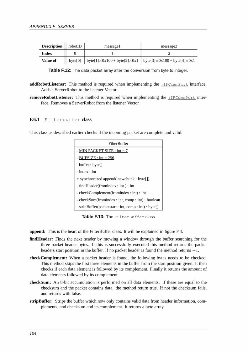
APPENDIX F. SERVER
Description robotID message1 message2
Index 0 1 2
Value of byte[0] byte[1]×0x100 + byte[2]×0x1 byte[3]×0x100 + byte[4]×0x1
Table F.12: The data packet array after the conversion from byte to integer.
addRobotListener: This method is required when implementing the :IFCommPort interface.Adds a ServerRobot to the listener Vector
removeRobotListener: This method is required when implementing the :IFCommPort inter-face. Removes a ServerRobot from the listener Vector
F.6.1 Filterbuffer class
This class as described earlier checks if the incoming packet are complete and valid.
FilterBuffer
- MIN PACKET SIZE : int = 7
- BUFSIZE : int = 256
- buffer : byte[]
- index : int
+ synchronized append( newchunk : byte[])
- findHeader(fromindex : int ) : int
- checkComplement(fromindex : int) : int
- checkSum(fromindex : int, comp : int) : boolean
- stripBuffer(packetstart : int, comp : int) : byte[]
Table F.13: The FilterBuffer class
append: This is the heart of the FilterBuffer class. It will be explained in figure F.4.
findHeader: Finds the next header by mowing a window through the buffer searching for thethree packet header bytes. If this is successfully executed this method returns the packetheaders start position in the buffer. If no packet header is found the method returns −1.
checkComplement: When a packet header is found, the following bytes needs to be checked.This method skips the first three elements in the buffer from the start position given. It thenchecks if each data element is followed by its complement. Finally it returns the amount ofdata elements followed by its complement.
checkSum: An 8-bit accumulation is performed on all data elements. If these are equal to thechecksum and the packet contains data. the method return true. If not the checksum fails,and returns with false.
stripBuffer: Strips the buffer which now only contains valid data from header information, com-plements, and checksum and its complement. It returns a byte array.
104

F.6. COMMPORT
[Check sumfailed]
[Check sum ok]
buffer end]valid at
[complements
return stripBuffer[Check sum failed]
[Check sum ok]
Empty buffer
Empty buffer
<6][buffersize
[buffersize >= 6]
to buffer
Append packet
Empty buffer
[Check sum failed]
[Check sum ok]
Empty buffer
[No header]
[No header]
Empty buffer
until next headercomplements
check for
until buffer endcomplements
check for
[Furtherheaders]
headers][No further
Save buffer
return stripBuffer
Empty buffer
at buffer end][Complements not vald
Empty buffer
return stripBuffer
Figure F.4: Activity diagram for the filterbuffer
105

APPENDIX F. SERVER
F.7 IFCommPort
This is an abstract class that specifies the methods required in the CommPort class.
IFCommPort
abstract
+ addRobotListener(obj : IFServerRobot)
+ removeRobotListener(obj : IFServerRobot)
+ sendPacket(data : byte[])
Table F.14: Contents of the IFCommPort interface.
addRobotListener: When implementing the IFServerMap interface this method must be over-ridden. It adds a RobotListener to the listener Vector. The parameter obj is an instance of aServerRobot which should be added to the listener vector
removeRobotListener: When implementing the IFServerMap interface this method must beoverridden. It removes a RobotListener from the listener Vector. The parameter obj is theServerRobot object which should be removed from the listener vector.
sendPacket: When implementing the IFServerMap interface this method must be overridden.It sends a packet which includes a packet header consisting of 0x55, 0xff and 0f00. Thisis followed by databytes which are followed by its complement. At last the checksum iscalculated by making an 8-bit accumulation of all databytes - this checksum is followed byits complement. This is the last two bytes of the packet. The parameter data is an array ofdatabytes that will be sent to the RCX. The method might throw a java.io.IOException.
F.8 IFServerRobot
This is an abstract class that specifies the methods required in the ServerRobot class.
run: When implementing the IFServerRobot interface this method must be overridden. It fa-cilitates the use of threads.
receiveMeasureData: When implementing the IFServerRobot interface this method must beoverridden. It receives measure data from the robot. It checks the length of the array todetermine whether it is a ping packet, a status packet or a data packet. For each of the twolast cases a private method in ServerRobot is called to validate the content of the array. Theparameter measureData is the data transmitted from the CommPort.
changeRobotClassState: When implementing the IFServerRobot interface this method mustbe overridden. It changes the robot state. The paramete robotClassState is state the classvariable that sets the value for all instances of the ServerRobot class. The instance variablerobotState is then changed by a method private to the object.
changeSearchState: When implementing the IFServerRobot interface this method must beoverridden. The method calls a private method in ServerRobot that alters the value of search-State between UNKNOWN_AREA and KNOWN_AREA. This result in the ServerRobotobject changing between searching and driving state.
106

F.9. IFSERVERMAP
IFServerRobot
abstract
+ run()
+ receiveMeasureData(measureData : int[])
+ changeRobotClassState(robotClassState : int)
+ changeSearchState()
+ setPosition(p : Point2D.Double)
+ setStartPosition(p : Point2D.Double)
+ getLastPosition() : Point2D.Double
+ getDirection() : int
Table F.15: Contents of the IFServerRobot interface.
setPosition: When implementing the IFServerRobot interface this method must be overridden.Stores the input in the variable position. The variable reflects the actual position of thephysical robot unit. Parameter p is the coordinate of the new position
setStartPosition: When implementing the IFServerRobot interface this method must be over-ridden. Stores the start postion of the robot. Parameter p is the coordinate of the newposition
getLastPosition: When implementing the IFServerRobot interface this method must be over-ridden. Retrieves the last value of position. Returns the position of the robot.
getDirection: When implementing the IFServerRobot interface this method must be overrid-den. Retrieves the last value of direction. Returns the direction of the robot.
F.9 IFServerMap
This is an abstract class that specifies the methods required in the class.
IFServerMap
abstract
+ addRobot(numberofrobots : int, linkCommPort : IFCommPort)
+ dataToMap(length : int, dirs : boolean[], robotID : int)
+ createSearch(robot : int) : int
+ createPath(robot : int) : int
+ evacuateRobot(robot : int) : int
+ createVisualMap() : VisualMap
+ changeMapState(command : int)
Table F.16: Contents of the IFServerMap interface.
107

APPENDIX F. SERVER
addRobot: When implementing the IFCommPort interface this method must be overridden. ItCreates a ServerRobot object representing each Robots in the maze. The parameter num-berofrobots is the number of robots connected to the server. The parameter linkCommPortis a link to the :CommPort object.
dataToMap: When implementing the IFCommPort interface this method must be overridden. Itstores new data recieved from robots. The parameters are
• length - is distance traveled by the robot since last upload.
• dirs - is an array of possible direction from the node the robot has arrived at.
• robotID - is the identification number of the robot from which the data was recieved.
createSearch: When implementing the IFCommPort interface this method must be overridden.It creates search instructions for the robot id which it is invoked with.
createPath: When implementing the IFCommPort interface this method must be overridden. Itcreates path for robot.
evacuateRobot: When implementing the IFCommPort interface this method must be overridden.It evacuates robots from maze, sends the robots back to origin.
createVisualMap: When implementing the IFCommPort interface this method must be overrid-den. It creates a visual map. It returns the VisualMap object that was created.
changeMapState: When implementing the IFCommPort interface this method must be overrid-den. It changes the map state and robot state. The parameter command is the state of themap that the method changes to.
F.10 The common package
F.10.1 Test
This class is used for testing and debugging of the other classes. It contains static methods forwriting strings to the standard output.
F.10.2 IFServerComm
This is an abstract class that specifies the methods required in the ServerComm class which im-plements this interface. It defines communication between Server and Client.
searchCommand: When implementing the IFServerComm interface this method must be over-ridden. It is used for receiving control commands in the server. The method might throw aRemoteException
changeSearchArea: When implementing the IFServerComm interface this method must be over-ridden. It invokes command on the server to change the search area. The method mightthrow a RemoteException.
getMap: When implementing the IFServerComm interface this method must be overridden. Itretrieves map from the server. The method might throw a RemoteException.
login: When implementing the IFServerComm interface this method must be overridden. Itsends username and password to the server. The method might throw a RemoteException
108

F.10. THE COMMON PACKAGE
IFServerComm
abstract
+ searchCommand(command : int, uid : IFAuth)
+ changeSearchArea(p : Point2D.Double, uid : IFAuth)
+ getMap(uid : IFAuth) : IFMap
+ login(user : String, pass : String) : IFAuth
Table F.17: Contents of the IFServerComm interface.
F.10.3 IFMap
This is an abstract class that specifies the methods required in the VisualMap class.
IFMap
abstract
+ setZoomFactor(zFactor : double )
+ paint(g : java.awt.Graphics)
+ mapDistance(active : boolean )
+ showRescuers(state : )
Table F.18: Contents of the IFMap interface.
setZoomFactor: When implementing the IFMap interface this method must be overridden. Con-trols zoom-factor on the map.
paint: When implementing the IFMap interface this method must be overridden. Renders mapgraphics.
mapDistance: When implementing the IFMap interface this method must be overridden. Con-trols measure of distances on the map.
showRobots: When implementing the IFMap interface this method must be overridden. Togglesdisplay of robots on the map (on/off).
showRescuers: When implementing the IFMap interface this method must be overridden. Tog-gles display of rescuers on the map (on/off)
F.10.4 IFSearchCommands
The IFSearchCommands contains constants used during searching.
109

.

Robot GThis appendix contains the design details for the software implemented on the robot. First a
method used for detecting vertices in the maze is described. Afterwards follows a description ofevery module with specification of their entry functions. Pseudo code for each process is shown atthe end of this appendix.
G.1 Detecting vertices in the maze
In this section it will be described how the robot is able to detect different vertices in the maze. Avertex is defined as where there are other options than driving forward in the maze.
To detect a vertex in the maze the different types of vertices has to be known. This knowledge istaken from appendix D on page 77 where the maze is described. Based on the types of vertices astrategy using the sensors on the robot will be introduced.
The strategy for detecting vertices is to continuously calculate the average of sensor values andthen detect when a new reading exceeds this average by a given limit. By monitoring the sidewayssensors it is possible to determine when a side path exists. The center sensor can be used todetermine whether a wall straight ahead exists or not. In figure G.1 on the following page thepossible vertices and how the sensors are measuring is shown.
G.1.1 Making correct detections
With the main strategy in focus, a number of methods to ensure correct detections are explained.
Comparing measurements: If too few measurements are compared, the risk of a false detectionincreases. This could be caused by corrupted sensor values. Therefore an average of thelast two measurements are calculated and then compared to the new measurement. If thedifference between them exceeds a “minimum change limit” a vertex is considered to bedetected.
Number of detections: If the robot arrives a little awry at a vertex it is possible that only onesideway path is detected, even if several paths exists. To deal with this the robot is setto drive a small step further and make another measurement, but using the average valuecalculated before the vertex was reached. This will ensure that all the possible paths aredetected.
The distance change: By defining a minimum change, which the new measurements must differfrom the average of the previous, a more reliable detection is obtained. The fact that theinput/output relation of the sensors are not linear is described in test report I.1. An output
111

APPENDIX G. ROBOT
change
(a) Right turn
change change
(b) T-turn
change
(c) Left turn
change
limit
(d) Right T-turn
change change
limit
(e) Cross
limit
change
(f) Left T-turn
(g)End
Figure G.1: The figures shows the possible vertices the robot should be able to detect. On eachfigure a robot is duplicated for showing two sensor measurements.
change from a sensor is greater at close range compared to the input change. Thus the char-acteristics of a sensor is approximated to real distances before calculating if the minimumlimit is exceeded.
On the graph G.2 on the next page the characteristic of each of the 6 sensors are showedalong with 4 straight limited lines approximating the characteristics. These lines will beimplemented in the software determining the vertices. The minimum change limit is defaultset to 15 cm.
112

G.2. DESCRIPTIONS OF MODULES
10 20 30 40 50 60 70 800
0.5
1
1.5
2
2.5
Distance [cm]
Ana
log
outp
ut v
olta
ge
Sensor 1Sensor 2Sensor 3Sensor 4Sensor 5Sensor 6
Figure G.2: The graph shows sensor characteristic of each sensor. The thick black line is anapproximation of the characteristics. The formula for the line is implemented in thesoftware detecting vertices.
G.2 Descriptions of modules
In the following sections the software modules on the robots is described. The term “RCX.command”means that a NQC command implemented in the RCX 2.0 operating system is used
G.3 Process Comm Server
G.3.1 Module: CommServer
Description: The module is responsible for communication with the server, including the handlingof incoming messages and outgoing data. The incoming messages are interpreted. Messagescontaining commands are added to the commandList. Messages which requires an answer areanswered. The process is able to interpret incoming messages even if the robot is performingprevious given commands. This module runs in a separate thread.
Interfaces:
1. inComingInput: voidFunction: This function continuously polls for new messages from the server. The received
113

APPENDIX G. ROBOT
“message” is interpreted and passed to newInstruction or dealt with internally (the “mes-sage” is stored temporarily in lastmessage.)Output: voidUses functions: CommandList.newInstruction; CommServer.uploadDataVariables: lastmessage
2. uploadDataInput: voidFunction: The function uploads the DataLog to the server sending a data packet containingup to 16 bytes.Output: voidUses functions: RCX.SENDSERIALVariables: DataLog
G.3.2 Module: CommandList
Description: This module performs operations on the CommandList. It is able to add commandmessages to the Commandlist or to clear the entire CommandList.
Interfaces:
1. fetchNextInput: voidFunction: This function gets the next command code instruction from CommandList andstores it in the variable newcommand. The command code is then removed from the list.Output: newcommand; NOERROR; LIST_EMPTYUses functions: NoneVariables: returnvalue; CommandList; newcommand
2. newInstructionInput: messageFunction: This function inserts the “message” in the CommandList. If the list is full an erroris returned.Output: NOEROR; LIST_FULLUses functions:Variables: returnvalue; message
G.4 Process Navigate
G.4.1 Module: Navigate
Description: This module fetches a command from the CommandList and performs the command.If the robot is either searching or driving all three modules Datalog, Control motors and Check-Vertex are used. When a vertex is detected the possible directions is stored in the DataLog and therobot uploads the data to server. This module runs in a separate thread.
114

G.4. PROCESS NAVIGATE
Interfaces:
1. performCommandInput: newcommandFunction: This function gets the next command using fetchNext. It executes the command,and updates the robotstate variable and loops.Output: NOERRORUses functions: CommandList.fetchNext; ControlMotors.driveForward; ControlMotors.turnLeft;ControlMotors.turnRight; ControlMotors.turnAround; CheckVertex.checkVertex; ReadDM-Sensors.readSensors; DataLog.savaData; CollisionControl.detectCollision.Variables: returnvalue; robotstate
G.4.2 Module: CheckVertex
Description: This module detects a vertex and the possible paths from it. It uses the process ReadSensors to detect and determine the vertices.
Interfaces:
1. checkVertexInput: voidFunction: This function checks for vertices using the DM sensor values and returns. If avertex is found it returns with VERTEX_FOUND, but first when the robot is placed at apoint in the vertex where it is able to make a turn.Output: VERTEX_FOUNDUses functions: NoneVariables: returnvalue; dmsensor1-3
G.4.3 Module: DataLog
Description: The module manages data about the maze structure. It stores information aboutactions performed, the distance traveled and the vertex found.
Interfaces:
1. saveDataInput: logvalue: Leftturn, Rightturn, Turned around Forward drive, argument.Function: This function saves the action performed, the distance traveled and the vertexfound.Output: NOERROR; DATALOG_FULLUses functions: NoneVariables: returnvalue; DataLog
2. clearDataLogInput: voidFunction: This function clears the current DataLog
115

APPENDIX G. ROBOT
Output: voidUses functions: NoneVariables: DataLog
G.5 Process Control Motors
G.5.1 Module: ControlMotors
Description: This module facilitates simple commands to turn and move the robot. The processuses feedback from Tachometers to remain on a straight course and to make turns.
Interfaces:
1. turnLeftInput: voidFunction: The function turns the robot 90 to the left. It uses the tachometer values asfeedback.Output: voidUses functions: ReadTachometers.readTachosVariables: SENSOR_1; SENSOR_3
2. turnRightInput: voidFunction: The function turns the robot 90 to the right. It uses the tachometer values asfeedbackOutput: voidUses functions: ReadTachometers.readTachosVariables: SENSOR_1; SENSOR_3
3. turnAroundInput: voidFunction: The function turns the robot 180. It makes the turn in 2 steps. First a 90 frontturn, then a 90 backwards turn. It uses the tachometer values to measure the turning angle.Output: voidUses functions: ReadTachometers.readTachosVariables: SENSOR_1; SENSOR_3
4. driveForwardInput: DRIVESTEPFunction: This function checks for collision before driving x tachocounts (DRIVESTEP)forward. While driving the function monitors the tacho values and makes small correctionsto maintain right course.Output: voidUses functions: CollisionControl.detectCollision; ReadTachometers.readTachos RCX.SENSOR_3(right sensor)Variables: SENSOR_1; SENSOR_3
116

G.6. PROCESS READ DM SENSORS
G.5.2 Module: CollisionControl
Description: This module detects collisions by supervising the values from the DM sensors. Ifthe robot gets too close to walls the module performs a correction. If its not applicable to makecorrection an error will be raised.
Interfaces:
1. detectCollisionInput: dmsensors1-3Function: This function decides from the sensor values whether the robot is in a criticalzone. The function makes a correction based upon which side of the robot that is to close toa wall.Output: MULTIPLEX_ERROR, TOO_CLOSEUses functions: ReadDMSensors.readSensorsVariables: returnvalue; collision.
G.6 Process Read DM Sensors
G.6.1 Module: ReadSensors
Description: This module controls multiplexing between the DM sensors and returns the read invalues.
Interfaces:
1. readSensorsInput: voidFunction: This function multiplexes between the connected DM sensors, and saves thevalues in variables dmsensors1-3Output: NOERROR; MULTIPLEX_ERRORUses functions: RCX.SENSOR_2 (multiplexer input); RCX.OnFor(OUT_A, “time”)Variables: returnvalue; dmsensors1-3.
G.7 Process Read Tachometers
G.7.1 Module: ReadTachos
Description: This module reads a counter value changed by Tachometers. The function is availablefrom the RCX 2.0 operating system.
117
APPENDIX G. ROBOT
Interfaces:
1. readTachoInput: voidFunction: This function saves the tacho values SENSOR_1 and SENSOR_2Output: voidUses functions: RCX.SENSOR_1 (left tachometer) or RCX.SENSOR_3 (right sensor)Variables: SENSOR_1; SENSOR_3
G.8 Pseudo code for processes
G.8.1 Process Comm Server
Module CommServer
1 inComm()2 initialize;3
4 loop 5 set IR power low;6 wait for a new message;7 set IR power high;8 check if the message is valid for this robot;9
10 switch (message) //interpret message11 case a command:12 update commstate;13 newInstruction(message); // pass it on to the commandlist14 update commstate;15 break;16 case GETSTATUS:17 update commstate;18 wait for semaphore;19 reply with robotstatus;20 signal semaphore;21 update commstate;22 break;23 case UPLOAD:24 update commstate;25 wait for semaphore; // only one session must be executed at a time26 uploadData(); // upload the datalog27 signal semaphore;28 update commstate;29 break;30 default:31 do errorhandling;32 update commstate;33 break;34 35 save the message as lastmessage;36 37 38
39 uploadData()40 wait for semaphore;41 send the Datalog;42 signal semaphore;43
118

G.8. PSEUDO CODE FOR PROCESSES
G.8.2 Module CommandList
1 // the commandlist is contained in a ring buffer2
3 // this function is called by Navigate4 fetchNext()5 wait semaphore; /*enter critical region6 the semaphore exist to protect7 variables in the ringbuffer8 */9
10 return if the commandlist is empty;11 else get the command;12 decrease the size of the commandlist;13 update the outputpointer;14 return noerror;15 signal semaphore; // exit critical region16 17
18 // this funtion is called by CommServer19 newInstruction(message)20 wait semaphore; //enter critical region21
22 //ringbuffer23 if the inputpointer is out of bounds 24 update the inputpointer;25 26 if the list is full 27 return that the list is full;28 29 else 30 insert the element;31 update the listsize;32 update the output pointer;33 34 signal semaphore; // exit critical region35 return noerror;36 37
G.8.3 Process Navigate
G.8.4 Module Navigate
1 void performCommand()2 // init3 initialize the system;4 start CommServer; // inComm5 // init complete6
7
8 fetchNext(); //fetch the next command, newcommand9
10 switch(newcommand)11 case TURNLEFT:12 update robotstate;13 turnRobot(LEFT);14 check returnvalue;15 saveData(TURNLEFT);16 update robotstate;17 break;18 case TURNRIGHT:19 update robotstate;20 turnRobot(RIGHT);21 saveData(TURNRIGHT);
119

APPENDIX G. ROBOT
22 check returnvalue;23 update robotstate;24 break;25 case TURNAROUND:26 update robotstate;27 turnRobot(AROUND);28 saveData(TURNAROUND);29 check returnvalue;30 update robotstate;31 break;32 case DRIVEFORWARD:33 update robotstate;34 loop 35 driveForward(STEP);36 check for collision;37 check for nodes;38 if a collision or the robot is at a vertex, break;39 40 saveData(DRIVEFORWARD);41 saveData(distance);42 if node 43 then saveData(node);44 45 update robotstate;46 break;47 case UPLOAD:48 update the robotstate;49 uploadData();50 update the robotstate;51 default:52 unknown command!;53 update the robotstate accordingly;54 55 56
57
58
Module DataLog
1 void saveData(int value)2 if the datalog is full 3 update robotstate;4 return error;5 6 else 7 wait for semaphore; /* avoid saving and sending data8 at the same time*/9 save the value;
10 increase datalogsize; //counter11 signal semaphore;12 13 14
15 clearDatalog()16 datalogsize =0;17 18
Module CheckNode
1 void checkNode()2 calculate the distance from the left sensor value;3 (using approximated 1. order polynomium lines);
120

G.8. PSEUDO CODE FOR PROCESSES
4 does it differ too much from the last measurement?;5 if so, mark that there is a right node;6 else save the value from the sensor7
8 calculate the distance from the right sensor value;9 (using approximated 1. order polynomium lines);
10 does it differ too much from the last measurement?;11 if so, mark that there is a left node;12 else save the value from the sensor;13
14 check if the center sensor value is close to a obstacle;15 if so, mark that there is a obstacle at the center sensor;16 else mark that there is a node ahead;17
18 return any nodes found;19 if the robot is at the "center" of the node (in the vertex)20 return this "state".21
G.8.5 Process Control Motors
G.8.6 Module ControlMotors
1
2 turnRobot(angle)3 clear counters for tachometers;4 if (angle==LEFT)5 brake left motor;6 right motor on until right_tacho == TURN_COUNTS;7 8 if (angle==RIGHT)9 brake right motor;
10 left motor on until left_tacho == TURN_COUNTS;11 12 if (angle == AROUND)13 turnRobot(right);14 brake left motor;15 right motor on until right_tacho == - TURN_COUNTS;16 17 18
19 driveForward(tachocounts x)20 clear counters for tachometers;21
22 while(x < tacho_values)23 drive_a_step;24 detectCollision;25 if (error) // errors \NOERROR, CANT_CORRECT \26 update returnvalue;27 ;28 29 30 return returnvalue;31
G.8.7 Module CollisionControl
1 detectCollision(sensorvalues)2 if (the robot is close to a side wall)3 save tachos values;4 if (side == RIGHT)5 brake left motor;6 turn right motor CORRECTION_TURN counts;
121

APPENDIX G. ROBOT
7 8 if (side == LEFT)9 brake right motor;
10 turn left motor CORRECTION_TURN counts;11 restore tacho values;12 13
14 if (too close)15 returnvalue = TOO_CLOSE;16 if (the robot is close to more than one side)17 return error;18
G.8.8 Process Read DM Sensors
Module ReadSensors
1 readSensors()2 multiplex until sensor_value > SENSOR_THRESHOLD;3 multiplex;4 save sensor_value in dmsensor[0];5 multiplex;6 save sensor_value in dmsensor[1];7 multiplex;8 save sensor_value in dmsensor[2];9
122

Communication between nodes HThis appendix covers the design of the network connections used in this project. The client/serverconnection is described in terms of how it is implemented in the JAVA programming language.Furthermore a description of the communication protocol used on application level is included.The underlying protocols are not described in this report. The server/robot connection is basedon a infrared connection included in the LEGO Mindstorms kit. For technical details about theusage of the IR technology see [Proudfoot 2003]. In section H.2 is a description of the protocoldesigned for controlling the communication flow between server and robot.
H.1 Client/Server communication
In the following section communication between the Server node and the Client node will bedescribed in terms of how objects are distributed with JAVA and what protocol is used in thisproject.
H.1.1 Distributing objects with JAVA
The JAVA programming language supports the distribution of object data as well as object behaviorover network via the Java Distributed Object Model, JDOM. The following outlines the mainfeatures of this model:
• A reference to a remote object can be passed as an argument or returned as a result in anylocal or remote method invocation.
• Clients interact with remote objects via remote interfaces
• When invoking remote methods with a reference to a remote object as argument, the RMIwill pass the argument as a remote reference to that same object.
• Non-remote arguments and results from a remote method invocation are returned as a deepcopy1 rather than by value.
The technique used in this project to distribute objects within the terms of JDOM is called Remotemethod Invocation (RMI).
The architecture of the RMI is divided in three layers as follows:
1. Stubs/skeletons: The stubs defined on the client side are implementations of remote interfacesto the objects, that needs to be transferred. These interfaces are defined as skeletons on the
1When making a deep copy the clone is totally seperated from the original. Changes applied to the original does notaffect the clone.
123

APPENDIX H. COMMUNICATION BETWEEN NODES
server side. When referencing to a remote object on the client side this is in fact a referenceto the stub.
2. The remote reference layer manages the process of extracting the behavior of the remote ob-ject from the client stub. Any call initiated by the stub is carried out directly through thereference layer.
3. The transport layer handles the actual sending/receiving of data from/to the client/server. Theobjects are decoded in to a byte stream from which they are reconstructed again after endtransmission, this process is called object serialization.
The boundary of each layer is defined with a specific interface and protocol, and they can thus bereplaced individually without affecting the other layers.[Microsystems 2003b]
H.1.2 Client/server protocol
The protocol consists of defining the methods that can be invoked via RMI and the objects thatneeds to be serialized and send over the network. In order to provide the first layer in the RMIarchitecture the appropriate interfaces needs to be defined. In the following the interfaces aredescribed on tabular form. The textual description of the functionality is provided where theinterface is implemented, see chapter 4 on page 29.
IFServerComm
+ searchCommand(comman : int, uid : IFAuth) throws RemoteException
+ changeSearchArea(p : Point2D.Double, uid : IFAuth) throws RemoteException
+ IFMap getMap(uid : IFAuth) throws RemoteException : IFMap
+ IFlogin(user : String, pass : String) throws RemoteException : Auth
Table H.1: The Interface IFServerComm
IFAuth
+ OPERATOR : int = 1
+ EXPERT : int = 2
+ UNKNOWN : int = 0
+ getUserType()
Table H.2: The Interface IFAuth
H.2 Robot/Server Communication
This section covers the design of the protocol used in the connection between server and robotsand is based on the demands from section 2.6.4 on page 20. The design of the protocol consist oftwo parts:
124

H.2. ROBOT/SERVER COMMUNICATION
IFMap
+ setZoomFactor(zFactor : double)
+ paint(g : Graphics)
+ mapDistance(active : boolean)
+ showRobots(state : boolean)
+ showRescuers(state : boolean)
Table H.3: The Interface IFMap
• The transmission of messages and appropriate answers.
• A procedure for uploading data from the robot to the server.
The LEGO Mindstorms firmware interface consist of a number of predefined byte codes, thatallows specific system calls into the RCX operating systems.[LEGO 2003] In order to transmitmessages to the robot the command SendPBMessage is used. This command broadcasts a mes-sage. This implies that the transmission band is divided into code intervals because a unique actionmost be performed. This is achieved by assigning each robot an id mapped to a “codebase”. Theactual message send is then codebase + message (the possible messages are listed in table H.4).The codebases are: Robot 1, codebase: 40. Robot 2, codebase: 60
Messages to a robot value RCX response Comment
PING 0 ROBOTID Determines whether the robot is alive or not
STATUS 1 robotstatus The robotstatus reflects the robot’s status
TURNLEFT 2 none Makes the robot take a path to the left
TURNRIGHT 3 none Makes the robot take a path to the right
TURNAROUND 4 none The robot makes a 180 turn
DRIVEFORWARD 5 none The robot drives forward
UPLOAD 6 ROBOTID+Datalog Uploads information about traveled route
CLEARCOMMANDLIST 7 none Deletes the command list stored on the robot
Table H.4: Message/commands to a robot.
Uploading data is performed when requested by the UPLOAD message or when the robot hasreached a new vertex. The data to be uploaded is the ROBOTID + the Datalog (table H.6 on thenext page).
Robotstatus
As a response to the STATUS message from the server the robot respond with one of the valueslisted in table H.5 on the following page.
125

APPENDIX H. COMMUNICATION BETWEEN NODES
Robotstatus value
WAITING 13001
DATA_READY 13002
TURNLEFT 13003
TURNRIGHT 13004
TURNAROUND 13005
DRIVEFORWARD 13006
UPLOADNG 13007
NODE_FOUND 13008
COMMAND_LIST_EMPTY 13009
UNKNOWN_COMMAND_ERROR 13010
LOW_BATTERY 13011
MULTIPLEX_ERROR 13012
COLLISION_ERROR 13013
Table H.5: Possible values of robotstatus
Value Meaning
12010 A TURNLEFT has been performed
12012 A TURNRIGHT has been performed
12014 A TURNAROUND has been performed
12016 A DRIVEFORWARD has been performed
1-? The argument for DRIVEFORWARD follows immediately after
the command (must be below 12010)
12047-12054 Bit masked values at a base of 2047,
which indicate possible directions at a vertex in the maze:
12047 | NODE_LEFT = 4 | NODE_RIGHT = 2 | NODE_LEFT 1
Table H.6: The datalog contains information about commands performed and distance traveled.The datalog can contain any of these listed codes, but is restricted to 7 values (eachvalue is represented as 2 bytes).
126

H.2. ROBOT/SERVER COMMUNICATION
Datalog
Any retransmission of TURNLEFT, TURNRIGHT, TURNAROUND, and DRIVEFORWARDdoesn’t have any effect when the robot is traveling between two vertices. In this way it’s possibleto retransmit the messages multiple times, which makes it more likely that the robot performs whatis desired.
Data and messages are always wrapped in a packet (standard RCX packet) as follows: preamblethen each databyte is followed by its complement, and then a checksum (the sum of the databytes)is added. This is described in table F.11 in appendix F.6.
The first databyte must always be the robot ID. The following databytes are one or more of thecodes defined in table H.6 on the preceding page.
127

.

Test of sensors IThe purpose of the following measurements is to determine the coherence between the analogoutput voltage and the distance for six DM-sensors and how a change in the angle of attack to thereflective object influence this relationship.
I.1 Determining the characteristics of the distance measurement sen-sors
A test done in advance of the following tests, see figure I.1, showed that the DM-sensors are ableto measure objects when the angle of attack is 45. This fact will be used when measuring eachsensors output voltage versus the distance. A measurement of how the angle of attack influencethe output voltage versus distance will have a more qualitative approach (that is, how much doesthe angle of attack influence).
0 10 20 30 40 50 60 70 800
0.5
1
1.5
2
2.5
Distance [cm]
Ana
log
outp
ut v
olta
ge
Figure I.1: This graph depicts a measurement done in advance. The proportion follows an ap-proximate hyperbolic curve as expected at an 45 angle of attack. The test is notfurther documented.
129

TEST REPORT I. TEST OF SENSORS
C
RL
45
y
x1
2
3 4
5
6C
RL
45
Figure I.2: Two sensor arrays are used, one for each constructed robot. The sensors, L, C andR are distributed 45 relative to each other, and numbered 1-6.
I.1.1 Scenarios
Measuring the voltage output versus distance
To know the coherence between distance and voltage output, and to examine in what degree thesensors can be considered as uniform, the voltage output versus the distance is measured on eachsensor.
The reflecting object is to be oriented as depicted in figure I.2, in order to keep the orientation inwhich they most frequently is measuring (most of the time the robot is driving parallel to a wallin the maze). To keep this angle of attack to the reflecting object when measuring, the “Center”sensor is measured by moving the “object” parallel to the x-axis, see figure I.3 on the facing page.To alter the distance when measuring the “Left” sensor, the sensor array is moved along the y-axis,hence the wooden surface on the x-axis is the reflector. The arrangement is mirrored vertical tocomplete the measurement for the “Right” sensor. Measurement is done at distances 10 − 40 cmwith 2 cm increment and 40− 80 cm with a 5 cm increment.
Measuring the voltage output versus angle and distance
To determine how the sensors are influenced by a change of the angle of the reflecting object, thevoltage output is measured versus distance at various angles. Only one sensor will be measuredthis way, as it is assumed that the result can be generalized to the others.
The measurement is performed at 10−80 cm, using the same intervals as previous, and at [25, 35,45, 75, 90], using the setup depicted in figure I.4 on the next page.
It’s possible to obtain a greater accuracy at shorter distances because the voltage changes more, asit’s seen from [Sharp 20. nov 2003][Figure 6] The graphing of voltage vs. distance is of hyperbolic
130

I.1. DETERMINING THE CHARACTERISTICS OF THE DISTANCE MEASUREMENTSENSORS
x
object
y
arraySensor-
Figure I.3: Measuring voltage output versus distance. The hatched surface is wooden. Thedistance is varied by sliding the “object” on the x-axis when measuring the sensorat the Center. When measuring the Left sensor, the Sensor-array is moved alongthe y-axis (so the IR light is reflected by the wooden surface). In case of measuringthe Right sensor, the y-axis is mirrored about the middle of the x-axis, and then theSensor-array is moved along the y-axis. The analog voltage output is measured witha multi-meter.
y
x
α
Figure I.4: Measuring voltage output versus distance and angle on sensor 1 (mounted “Left”).The actual angle measured is α + 45.
131

TEST REPORT I. TEST OF SENSORS
form as mentioned in section C.1.1 on page 73). Because of this fact more measurement will beperformed at shorter distances.
In both scenarios the DM-sensors is supplied with 6x1,5V through a voltage regulator, LM7805.This supply voltage is sampled when a new sensor is to be measured. The output from the DM-sensor is connected to the multiplexer in order to establish the conditions under which the DMsensors are to be used.
To measure the distance from the sensor to the reflective object, the actual distance is convertedto distances on the x- and y-axis, so it is possible with rulers on each axis, to obtain the actualdistance.
I.1.2 Equipment used
Number Type Model Serial nr.
1 Oscilloskop Agilent 54621A 33865
1 Multimeter Kikusi, model 1502 08112
1 Triangle 15 cm with protractor, 1 resolution
2 Rulers, 80 cm, 0, 05 cm resolution
Table I.1: Equipment used
I.1.3 Data from measurement
On the four following figures (I.5, I.6, I.7 and I.8) the analog output voltage is a function of thedistance from the sensor to the reflective object.
I.1.4 Discussion
The supply voltage was constant at all time, 5, 04V , and hence has not influenced the measure-ments.
Figure I.9 shows that sensors mounted in the same position in the “sensor array” has the mostalike proportions. All graphs follows a hyperbolic like curve, the difference is a voltage offset,except at longer distances where the “Center” sensor is falling outside. This offset is properlybecause the IR-transmitter and receiver are not placed in the center of the sensor, see figure I.10.This result in a shorter distance for the “Right” sensor than the “Left”, id est they are displacedcompared with the “Center”. This also explains the convergence as the distance increase, becausethe IR-transmitter and receiver also converge to a single point (the center of the sensor).
The graphs for sensor 2, 3, 4 and 6 shows sudden changes and the curve deviate from the expectedhyperbolic form.This applies for sensor 2 at 56 cm, sensor 4 at 58 cm, sensor 3 and 6 at 64 cm).This change could be the result of a small amount of data-points and an increasing uncertaintyabout the actual distance. It’s doubtfully the sensors since they show continuous sequences onothers graphs.
132

I.1. DETERMINING THE CHARACTERISTICS OF THE DISTANCE MEASUREMENTSENSORS
10 20 30 40 50 60 70 800
0.5
1
1.5
2
2.5
Distance [cm]
Ana
log
outp
ut v
olta
ge
Sensor 1Sensor 2Sensor 3
Figure I.5: Measurements on sensor 1, 2 and 3
10 20 30 40 50 60 70 800
0.5
1
1.5
2
2.5
Distance [cm]
Ana
log
outp
ut v
olta
ge
Sensor 4Sensor 5Sensor 6
Figure I.6: Measurements on sensor 4, 5 and 6
133

TEST REPORT I. TEST OF SENSORS
10 20 30 40 50 60 70 800
0.5
1
1.5
2
2.5
Distance [cm]
Ana
log
outp
ut v
olta
ge
Angle 25Angle 35
Figure I.7: Measurements on sensor 1 at 25 and 35
10 20 30 40 50 60 70 800
0.5
1
1.5
2
2.5
Distance [cm]
Ana
log
outp
ut v
olta
ge
Angle 45Angle 75Angle 90
Figure I.8: Measurements on sensor 1 at 45 , 75 and 90
134

I.1. DETERMINING THE CHARACTERISTICS OF THE DISTANCE MEASUREMENTSENSORS
10 20 30 40 50 60 70 800
0.5
1
1.5
2
2.5
Distance [cm]
Ana
log
outp
ut v
olta
ge
Sensor 1Sensor 2Sensor 3Sensor 4Sensor 5Sensor 6
Figure I.9: Measurements on sensor 1-6. The line types represent a placement in the sensorar-ray. Dashdot: Left, solid: Center, dashed: Right
IRreceiver IRtransmitter
Figure I.10: The layout of a DM sensor. The IR-transmitter/receiver is not placed at the center
135

TEST REPORT I. TEST OF SENSORS
As the angle is changed, see fig. I.7 and I.8, the curves shows convergent at 10 cm and 80 cm,but different curves connecting the points. At a more acute angle the voltage output is lower. At60 − 80 cm the data-points for the measurement at 90 is falling outside the other curves. Thedifference between “Angle 25” and “Angle 90” is about 5 cm at maximum except at distanceshigher than about 60 cm. The curves for the measurements “Angle 25” and “Angle 35” differs themost.
When the angle of attack is changed from 90 to 75 the curve is still very similar indicated thatthe sensors mounted in the “Center” position have a low uncertainty, below about ±1 cm, whenthe angle doesn’t change more than ±15 (assuming that the deviation is similar at 90 + 15).The sensors in the “Left” and “Right” positions, which are in a 45 direction as default, have ahigher uncertainty when comparing “Angle 25, 35, 45”. The difference from “Angle 25” to “Angle45” is (by inspection) no more than 4 cm. It’s about 2 cm between “Angle 35” and “Angle 45”.
So with an angle 45±20 the uncertainty is approximately ±4 cm and about ±2 cm at 45±10
I.2 Conclusion
When the measurements of each sensors are used to calculate the distance from a voltage output(by regression), it can be fairly accurate. The uncertainty increases with the distance. When theangle of the reflective object changes the uncertainty further increases. Assuming the angle doesn’tchange more than 10 , the uncertainty will be no more than about ± 2 cm between 10 − 60 cmfor all 6 sensors (the measurement for each sensor must be used to convert between distance andoutput). At an increasing distance the voltage difference becomes smaller but the angle of thereflective object seems to have a smaller influence (at an angle different than 90 ). It is estimatedthat a accuracy of ±5 cm can be obtained when the distance is higher than 60 cm.
136

Test of Client Node IIII.1 Test of the client node
Methods in the developed classes has been tested iteratively by inspecting the source code anddebug information from the stdout. Most of the classes is developed by extending existing classesfrom the javax.swing package and are as such assumed to work corresponding to the specifiedAPI, (see [Microsystems 2003a]).
Purpose of the test
The client must be tested to meet the requirements listed in section 4.2 on page 33.
II.1.1 Test Design
The client must display the map correctly and update it (every second) along with the positions ofrobots whenever new paths are added to the :VisualMap.
A simulation including the classes: Auth, ServerComm, ServerHandler, VisualMap andServerMap is carried out to test whether the GUI is able to draw a map onscreen. A virtualmap is generated replacing the :VisualMap object which is passed to the client.
Furthermore messages from client to server, e.g. start, stop and evacuate, must be confirmed, andfunctionalities as zoom, history and showing details inspected.
II.1.2 Implementation
Messages from client to server are confirmed by inspecting prints to stdout, by adding a print outline in the used methods. Features as zoom, history and showing details are inspected visually.
The creation of a :VisualMap is enabled by setting a variable in the ServerHandler. When thesystem is initiated by the client, :ServerMap will return a generated :VisualMap, and the resultcan be inspected visually.
137

TEST REPORT II. TEST OF CLIENT NODE
II.1.3 Results
Figure II.1 shows a screenshot of the GUI. The map was drawn and updated correctly along withthe robots position. It was possible to toggle the display of robots and rescuers on/off, zoom atfour different levels, and to scroll in the history panel to see previous executed commands. Thefunctions to pass the signals start, stop and evacuate were invoked successfully.
Figure II.1: Screenshot of the Gui connected to the server running in test mode
138

Test of Server Node IIIIII.1 Test of ServerRobot class
This sections documents the test performed on the ServerRobot class. The documentation con-sist of test design, the obtained results and an analysis of the these.
Purpose of the Test
The ServerRobot class is to be systematically tested with regard to the transitions between thestates that :serverRobot object can assume. The success criteria is not to test all possiblesequences of transitions, since this is practically impossible. In order to establish that the class be-haves in the intended manner four test scenarios are applied. These are described in section III.1.1.The functionality of the methods in the class are tested by inspection.
III.1.1 Test Design
The design of the test is based upon figure III.1. The four paths described below are chosen torepresent the most common behavior of the system.
1 It is tested that a search can be initiated and data collected from the robot. This is iteratedonce to represent a situation with more than one unknown vertex. In the same scenario it isalso tested that the search can be terminated from state 4 on figure III.1.
1-2-3-4-3-4-1
2 It is tested whether the detection of an error results in a transition to the error state (state 11on figure III.1). The only error processing implemented in this design is the detection of theerror, i.e. the error state, followed by a transition to the idle state. This results in the testingof the following transition sequence:
1-2-3-11-1
3 It is tested if a search can be changed to a drive along a known route and back to search ifunknown area is reached. This results in the testing of the following transition sequence:
1-2-3-4-5-6-7-6-7-2-3-4-1
139

TEST REPORT III. TEST OF SERVER NODE
4 It is tested whether the robots can be evacuated during a search. This involves bringing the:ServerRobot object into evacuating state and then to idle state when the start position isreached. This results in the testing of the following transition sequence:
1-2-3-4-8-9-10-1
2 3 4
5 8 106 97
1
11
EVACUATING
SEARCHINGIDLE
ERROR
DRIVING
Figure III.1: This figure is a simplifed version of the state diagram of the ServerRobot class.The main classes are marked with the dashed boxes.
III.1.2 Implementation
The test is done by setting the variables that are directly or indirectly set by methods in otherclasses.
robotClassState This variable can assume the values START, STOP, EVACUATE and is set uponrequest from the :ServerMap. This is a class variable applying to all instances of theServerRobot class. The instance object checks the value of this variable and sets its owninstance variable, robotState. The variable is responsible for transitions between states: idle,searching and evacuating.
searchState This variable can assume the values UNKNOWN_AREA and KNOWN_AREA andis set upon request from the :ServerMap object. These values brings the :ServerRobotobject to either the driving state or searching state.
dataArrived This variable is set whenever a data package of the correct format has been receivedfrom the :commPort object. It can assume the values DATA_OK or NO_DATA.
The procedure for setting these variables is more thoroughly described in the design appendix F.Table III.1 contains the values that needs to be applied to the variables in order to perform thetransitions depicted on figure III.1. The X represents when the variable is a don’t care. In the testthe don’t cares where set to 0.
140

III.2. TEST OF THE SERVERMAP CLASS
Transition robotClassState searchState dataArrived statusValue
1-2 START X X X
1-8 EVACUATE X X X
2-3 X X X X
3-4 X X DATA_OK STATUS_OK
4-1 START UNKNOWN_AREA X STATUS_OK
4-3 START UNKNOWN_AREA X STATUS_OK
4-5 START KNOWN_AREA X STATUS_OK
4-8 EVACUATE X X STATUS_OK
4-11 !STOP X X STATUS_ERROR
5-6 X X X X
6-7 X X DATA_OK STATUS_OK
7-1 STOP X X X
7-2 STARTUNKNOWN_AREA X STATUS_OK
7-6 START KNOWN_AREA X X
7-8 EVACUTE X XSTATUS_OK
7-11 !STOP X X STATUS_ERROR
8-9 X X X X
9-10 X X DATA_OK STATUS_OK
10-1 STOP X X X
10-9 EVACUATE X X STATUS_OK
10-11 !STOP X X STATUS_ERROR
11-1 X X X X
Table III.1: The transitions between the states in the ServerRobot class The X representswhen the variable is a don’t care
III.1.3 Results
III.1.4 Conclusion
The purpose of this test was to verify that the correct state transitions where performed whenapplying the scenarios described in the test design. The only deviation from the expected sequenceoccurs in sequence 4. The expected transition does however occur even though it is late. Sinceno data is added to the map in the evacuate state, this is not considered to be a severe error. Itwas decided to approve the test and consider this error again if any problems should occur whenperforming acceptance test on the overall system.
III.2 Test of the ServerMap class
The ServerMap class and the additional classes needed for implementation have been tested viathe following steps. First the NavMap class was tested and included in this test was the MapNodeclass. Next the SearchMap class was tested to see if the correct decisions were made.
141

TEST REPORT III. TEST OF SERVER NODE
Sequence 1:
Expected sequence : 1 2 3 4 3 4 1Obtained sequence : 1 2 3 4 3 4 1
Sequence 2:
Expected Sequence : 1 2 3 11 1Obtained Sequence : 1 2 3 11 1fixErrors()-unknown error statusValue=-1
Sequence 3:
Expected Sequence : 1 2 3 4 5 6 7 6 7 2 3 4 1Obtained Sequence : 1 2 3 4 5 6 7 6 7 2 3 4 1
Sequence 4:
Expected Sequence : 1 2 3 4 8 9 10 9 10 1Obtained Sequence: 1 2 3 4 8 9 10 9 10 10 10 1
Figure III.2: The above results is simply the output when running the program in test mode. Thestatus value shown under sequence 2 shows an unknown error since the statusvalue was set to an undefined value during test.
III.2.1 Test of the NavMap class
The NavMap class was tested by developing a main method in the NavMap class that constructs atest :NavMap object. This constructor also adds nine points as if the robot has driven along thepath depicted on figure III.3. After adding the vertices a print method (printNavMap) is called
➆➅
➄
➃
➂➁
➀
(-100,-100)
(-100,0)
(0,-100)
(100,0)
(100,100)(0,100)
(0,0)
Figure III.3: The figure shows the paths which the “robot” supposedly drove. The starting pointwas (0,0). This was the end point as well.
which sends the map structure to standard out.
Results
The result of the test is presented in table III.2 on the facing page. The first point ➀ is supposedbe connected to the four points: North ➁, East ➃, South ➄ and West ➆. This is as it’s seen not thepoints written. This is because the map structure uses negative values as north.
142

III.2. TEST OF THE SERVERMAP CLASS
Vertex Position North East South West Approved
➀ (0,0) (0,-100) (100,0) (0,100) (-100,0)
➁ (0,-100) NC (100,-100) (0,0) NC
➂ (100,-100) NC NC (100,0) (0,-100)
➃ (100,0) (100,-100) NC NC (0,0)
➄ (-100,0) NC (0,0) (-100,100) NC
➅ (-100,100) (-100,0) (0,100) NC NC
➆ (0,100) (0,0) NC NC (-100,100)
Table III.2: Results of the NavMap test. NC means Not Connected.
Conclusion
The map structure build by the NavMap class is as it’s seen on figure III.2 like expected.
III.2.2 Test of the SearchMap class
A main method was developed for testing the SearchMap as well. A test :SearchMap object isconstructed with a link to a :DummyServerRobot object and a test method is run. The goal ofthe test is to see if the SearchMap class chooses the correct turn according to a preference (seesection section D.1 on page 78). This is done by running three scenarios four time (once wherethe robot face north, east, south and west). The scenarios is the three different preferences.
Results
The results were checked by printing them to stdout as the test went along. These are seen below.The first line printed is the direction of the robot. The next is the possible paths away from thenode and the next is the relative direction to the robots current direction. This is one of parametersof the test. Next is the search preference written and last the chosen drive instruction.
1 testing SearchMap2 Direction of robot NORTH3 Possible paths from the node : NORTH EAST SOUTH WEST4 false true false true5 Possible relative paths : FORWARD RIGHT BACK LEFT6 false true false true7 The preference : LEFT8 The chosen driveinstruction LEFT_TURN9
10 Direction of robot EAST11 Possible paths from the node : NORTH EAST SOUTH WEST12 false true false true13 Possible relative paths : FORWARD RIGHT BACK LEFT14 true false true false15 The preference : LEFT16 The chosen driveinstruction FORWARD_DRIVE17
18 Direction of robot SOUTH19 Possible paths from the node : NORTH EAST SOUTH WEST20 false true false true21 Possible relative paths : FORWARD RIGHT BACK LEFT
143

TEST REPORT III. TEST OF SERVER NODE
22 false true false true23 The preference : LEFT24 The chosen driveinstruction LEFT_TURN25
26 Direction of robot WEST27 Possible paths from the node : NORTH EAST SOUTH WEST28 false true false true29 Possible relative paths : FORWARD RIGHT BACK LEFT30 true false true false31 The preference : LEFT32 The chosen driveinstruction FORWARD_DRIVE33
34 Direction of robot NORTH35 Possible paths from the node : NORTH EAST SOUTH WEST36 false true false true37 Possible relative paths : FORWARD RIGHT BACK LEFT38 false true false true39 The preference : RIGHT40 The chosen driveinstruction RIGHT_TURN41
42 Direction of robot EAST43 Possible paths from the node : NORTH EAST SOUTH WEST44 false true false true45 Possible relative paths : FORWARD RIGHT BACK LEFT46 true false true false47 The preference : RIGHT48 The chosen driveinstruction FORWARD_DRIVE49
50 Direction of robot SOUTH51 Possible paths from the node : NORTH EAST SOUTH WEST52 false true false true53 Possible relative paths : FORWARD RIGHT BACK LEFT54 false true false true55 The preference : RIGHT56 The chosen driveinstruction RIGHT_TURN57
58 Direction of robot WEST59 Possible paths from the node : NORTH EAST SOUTH WEST60 false true false true61 Possible relative paths : FORWARD RIGHT BACK LEFT62 true false true false63 The preference : RIGHT64 The chosen driveinstruction FORWARD_DRIVE65
66 Direction of robot NORTH67 Possible paths from the node : NORTH EAST SOUTH WEST68 false true false true69 Possible relative paths : FORWARD RIGHT BACK LEFT70 false true false true71 The preference : FORWARD72 The chosen driveinstruction RIGHT_TURN73
74 Direction of robot EAST75 Possible paths from the node : NORTH EAST SOUTH WEST76 false true false true77 Possible relative paths : FORWARD RIGHT BACK LEFT78 true false true false79 The preference : FORWARD80 The chosen driveinstruction FORWARD_DRIVE81
82 Direction of robot SOUTH83 Possible paths from the node : NORTH EAST SOUTH WEST84 false true false true85 Possible relative paths : FORWARD RIGHT BACK LEFT86 false true false true87 The preference : FORWARD88 The chosen driveinstruction RIGHT_TURN89
90 Direction of robot WEST91 Possible paths from the node : NORTH EAST SOUTH WEST
144

III.2. TEST OF THE SERVERMAP CLASS
92 false true false true93 Possible relative paths : FORWARD RIGHT BACK LEFT94 true false true false95 The preference : FORWARD96 The chosen driveinstruction FORWARD_DRIVE97
Conclusion
As seen the SearchMap chooses the right drive instruction and the SearchMap class is approved.
145

.
Test of Robot Node IVIV.1 Test of the robot node
This appendix covers the tests performed on the robot node. The purpose of the various tests aredefined and the implementation of them is described. A conclusion is made based on the resultslisted in table IV.1.3.
Tests during the development of the server.CommPort showed that the :CommPort was able toreceive and interpret data from a RCX correctly. The robot was also able to receive instructionsand carry them out properly.
Purpose of the test
The purpose of this test is determine if the robots are able to detect vertices and communicate thisresult correctly. Furthermore the robot must not collide with any wall in the maze.
IV.1.1 Test Design
The server.CommPort serves as a starting point, that is, the test will include theserver.CommPort and the robot.
Test # 1
The first test will be to determine if the robot detects vertices in the maze correctly. It will beexposed to all possible vertices described in section G.1 on page 112, and must then communicateits traveled path to the vertex, and which paths the vertex contains, complying to the protocol(section H.2 on page 124).
Test # 2
The second test will be to determine the reliability of the :CommPort and a robot. A test programincluded in the server.CommPort generates a random valid instruction on the basis of the re-turned information of the reached vertex from the robot. This command is then send to the robot.By running this test program over a longer time without any collisions, a correct detection and
147

TEST REPORT IV. TEST OF ROBOT NODE
communication, the server.CommPort and the robot is assumed to be at a acceptable level. Thistest will run for half an hour, enough time for the robot to travel through all vertices several times.
IV.1.2 Implementation
The first test will be carried out by placing the robot about 0, 3m away from the type of vertex thatmust be detected. A “drive-forward” command is send. When the robot reaches the vertex it mustcommunicate the result to the server.CommPort. When testing the result will be printed to thescreen.
In the second test the robot is placed about 0, 3m from any vertex. A “drive-forward” commandis send to initialize the test program. When a vertex is reached the robot must communicate theresult to server.CommPort, which then picks a random valid path from the vertex and sends thecorresponding command.
IV.1.3 Results
Test # 1
The first was successful as table IV.1.3 depicts.
Test Received data Result
#ID Last command Distance[counts] Vertex
Right-turn 1 DRIVE 80 right path
T-turn 1 DRIVE 165 left and right path
Left-turn 1 DRIVE 231 left path
Right T-turn 1 DRIVE 132 forward and right path
Cross 1 DRIVE 130 left, forward and right path
Left T-turn 1 DRIVE 230 left and forward path
Dead end 1 DRIVE 130 no paths
Table IV.1: Results from the first test: Test of correct vertex detection. A indicates that theresult was as expected, and that the server.CommPort and robot acts as specified.A indicates that the test revealed a flaw or a fault. The distance is measured intachometers counts. A count is approximately 0, 3 cm.
Test # 2
The second test was a success although the robot was at several time close to the wall. It didhowever manage to correct its course and continue the navigation. All vertices was traveled atleast once.
148

IV.1. TEST OF THE ROBOT NODE
IV.1.4 Conclusion
The robot was able to detect the different kind of vertices it is possible to encounter in the mazeand communicate the correct information to the :CommPort. The second test ran over a longerperiod of time and showed that the system is stable. Hence the server.CommPort and the robotnode is at a functional and acceptable level.
149

.

Acceptance test specification VThe purpose of the accept test specification is to confirm that all use cases created
in the system specification are implemented correctly and is fully operable. In orderto find errors numerous test criterias are formulated and described in terms of howthe test is done.
V.1 Functionality test
This section describes how all use cases will be tested. The test is designed so that a criterion istested with questions where the only answer options are “yes” or “no.”
V.1.1 Client use-cases
1. User authenticationTest criteria: Is the operator and expert able to log on and off?Conditions: The server is running and users are registered as user of the system.Input:
(a) User opens program.(b) User enters “ID” and password.(c) User presses either “File → Quit” or “Alt-F4.”
Description: When users log on to the system, he is prompted for a ID and password, ifusers type in either an incorrect password or ID the system will prompt for log on again.
2. Start/stop searchTest criteria: Is the operator able to control the system and just as important make sure thatthe expert can not.
(a) Is the operator able to start a new search.(b) Is the operator able to stop a started search.(c) Is the operator able to resume a stopped search.
Conditions: The operator (or expert) is logged on.Inputs:
(a) The operator presses “Start”.(b) The operator presses “Stop”.(c) The operator presses “Start”.
151
TEST REPORT V. ACCEPTANCE TEST SPECIFICATION
Description: When the operator is logged on he can start a search, when this is done he canstop the search. Then he can resume the search by activating start again. The expert shouldnot be able to activate any buttons that affects the search.
3. Change search areaTest criterion: Is the operator able to change the search areaConditions: The operator is logged on.Input: The operator presses “Search area”Description: When the operator is logged in he can change the search area, this makes therobots search in the direction chosen.
4. Display mapTest criterion: Does a graphical map appear on the Graphical User Interface on the client.Conditions: The server started and start search activated.Input: None.Description: It is tested if a map is drawn after a search has been started
5. Zoom on mapTest criterion: Are the Users able to change the zoom level on the graphical map to either,100 %, 50 %,25 %, or 10 %.Conditions: A user is logged on.Inputs:
(a) The user presses “100%”
(b) The user presses “50 %”(c) The user presses “25 %”(d) The user presses “10 %”
Description: The user can either zoom in or out on the graphical map in four predefinedscales.
6. Measure distance on mapTest criterion: Are the users able to measure a distance on the map from point A to point Bgiven by the user. To check the result it’s required that the distance is known.Conditions: A user logged on.Inputs:
(a) A user activates “Measure”(b) Then the user chooses “point A”(c) Then the user chooses “point B”
Description: The distance between two point is displayed to the user.
7. Choose detailsTest criterion: Are the users able to enable/disable showing robots and/or rescuers on thegraphical map.Conditions: A user logged onInputs:
152

V.2. SYSTEM PERFORMANCE
(a) The user enables “Show robots on map”(b) The user enables “Show rescuers on map”(c) The user disables “Show robots on map”(d) The user disables “Show rescuers on map”
Description: The user can choose to show/hide robots and/or rescuers on the graphical map.
8. Save mapTest criterion: Are the users able to save the graphical map.Conditions: A user logged on.Input: User presses either “File → Save as” or “Ctrl-s”Description: The user can save the graphical map to a disk.
9. Print mapTest criterion: Are the users able to Print the graphical mapConditions: A user logged on.Input: User presses either “File → Print” or “Ctrl-p”Description:
10. Evacuate robotsTest criterion: Is the operator able to evacuate the robots.Conditions: operator logged in and search started and robots placed in the mazeInput: operator presses “Evacuate”Description: The operator can evacuate the robots making them return to their starting pointin the maze.
V.1.2 Server and Robot use-cases
The server and robot use-cases will not be tested directly in this acceptance test. Instead a test ofsystem performance will be made. Following tests are of a more qualitative character, and maynot be confirmed with a “yes” or “no”. The tests are evaluated in the acceptance test.
V.2 System performance
11. Robot activityTest criterion: Does the robots travel around in the maze.Conditions: Both robots are in the maze and a search is being performed.Description: This test is made to ensure that both robots drive around in the maze when theoperator has started a search.
12. Update of mapTest criterion: Does the map displayed on the client correspond to the path travel by a robot.Conditions: A search has been started.Description: This test is to ensure that the collected and displayed information from themaze corresponds to the actual appearance of it.
153

TEST REPORT V. ACCEPTANCE TEST SPECIFICATION
13. Collision with walls and other objectsTest criterion: Does the robots avoid walls and/or other robots.Conditions: The robots are placed in maze, and a search is being performed.Description: This test is made to find out if the robots are able to avoid hitting other objectsin the maze.
14. Cooperation of the robotsTest criterion: Does the robots co-operate appropriately.Conditions: Robots placed in maze, and a search is being performed.Input: System initiatedDescription: This test is made by observing the two robots traveling around the maze, theresult of this test is an subjective evaluation of the cooperation.
15. Comparing search timeTest criterion: Is the maze searched faster with two robots than with one.Conditions: Robots placed in maze, and a search is being performed.Description: The first test is made with one robot. The second is made with two robots. Thesearch times for a complete search of the maze are compared. Is it faster with two robots?
16. Change of search focusTest criterion: Is the search preference of the robots changed.Conditions: Robots placed in maze, and a search is being performed. The operator has thenchosen a new search area to focus on.Description: This test is made by observing the two robots when new search area has beenchosen. Does the robots travel to the designated area and in a fast way?
154