Embed Size (px)
Citation preview
Aalborg Universitet
Generic inertia emulation controller for multi-terminal voltage-source-converter highvoltage direct current systemsZhu, Jiebei; Guerrero, Josep M.; Hung, William; Booth, Campbell D.; Adam, Grain P.
Published in:IET Renewable Power Generation
DOI (link to publication from Publisher):10.1049/iet-rpg.2014.0109
Publication date:2014
Document VersionEarly version, also known as pre-print
Link to publication from Aalborg University
Citation for published version (APA):Zhu, J., Guerrero, J. M., Hung, W., Booth, C. D., & Adam, G. P. (2014). Generic inertia emulation controller formulti-terminal voltage-source-converter high voltage direct current systems. IET Renewable Power Generation,8(7), 740-748. DOI: 10.1049/iet-rpg.2014.0109
General rightsCopyright and moral rights for the publications made accessible in the public portal are retained by the authors and/or other copyright ownersand it is a condition of accessing publications that users recognise and abide by the legal requirements associated with these rights.
? Users may download and print one copy of any publication from the public portal for the purpose of private study or research. ? You may not further distribute the material or use it for any profit-making activity or commercial gain ? You may freely distribute the URL identifying the publication in the public portal ?
Take down policyIf you believe that this document breaches copyright please contact us at [email protected] providing details, and we will remove access tothe work immediately and investigate your claim.
Downloaded from vbn.aau.dk on: juni 15, 2018
This document downloaded from www.microgrids.et.aau.dk is the preprint version of the final paper: J. Zhu, J. M. Guerrero, W. Hung, C. D. Booth, and G. P. Adam, “A generic inertia emulation controller for multi-terminal VSC-HVDC systems,” IET Renewable Power Generation, 2014.
A generic inertia emulation controller for multi-terminal VSC-HVDC systems
Jiebei Zhu*, Josep M. Guerrero†, William Hung-, Campbell D. Booth^, Grain P. Adam^
* National Grid, UK. Email:[email protected]
†Aalborg University, Denmark. Email: [email protected] -Independent Power System Consultant, UK. Email: [email protected]
^University of Strathclyde, UK..Email: [email protected]; [email protected]
Keywords: Virtual inertia, inertia emulation, frequency response, multi-terminal HVDC, MTDC, HVDC
converters, HVDC transmission control, island mode.
Abstract
A generic Inertia Emulation Controller (INEC) scheme for Multi-Terminal Voltage-Source-Converter based
HVDC (VSC-MTDC) systems is proposed and presented in this paper. The proposed INEC can be incorporated in
any Grid-side Voltage-Source-Converter (GVSC) station, allowing the MTDC terminal to contribute an inertial
response to connected AC systems during system disturbances, in a fashion similar to synchronous generators. The
DC link capacitors within the MTDC are utilised by the INEC scheme to exchange stored energy with the AC
system by varying the overall DC voltage level of the MTDC network within a safe and pre-defined range. A
theoretical treatment of the INEC algorithm and its implementation and integration within a conventional VSC
control system are presented, and the impact on the total DC capacitance required within the MTDC network to
ensure that DC voltages vary within an acceptable range are discussed. The proposed INEC scheme is validated
using a Matlab/Simulink model under various changes in demand and in response to AC network faults. The model
incorporates a multi-machine AC power system connected to a MTDC transmission system with multiple
converter-interfaced nodes. The effectiveness of the INEC in damping post-fault oscillations and in enhancing AC
system frequency stability is also investigated. The system is shown to perform well and is attractive for providing
a stable MTDC system that is capable of providing valuable support to the connected AC systems.
Invited manuscript for IET Renewable Power Generation Journal by 2013 2nd Renewable Power Generation Conference Committee
1 Introduction
The fast pace of the development of renewable power generation has raised many technical issues. A major
concern associated with renewables energy resources is with respect to their limited capability to support system
frequency management, when compared to conventional synchronous, directly-connected, power generation units.
Power system frequency is a global indicator of the balance between active power generation and demand. Any
short-term active power imbalance results in a change of system frequency; the rate of which varies depending on
the nature of the disturbance, the prevailing system inertia and installed generation system capacity. In general, a
higher value of aggregated system inertia leads to higher frequency stability and system security.
An increasing penetration of wind power generation may act to deteriorate system frequency stability. This is
primarily due to two reasons:
i) Typical wind turbine generators (WTGs) have lower inertia than traditional synchronous power
generation plant [1] and their inherent inertial response to changes in frequency is relatively reduced or
even eliminated;
ii) The majority of wind turbine generators and other forms of renewable energy sources (e.g. fuel cells,
tidal and wave power) use power electronic interfaces or HVDC links, decoupling the kinetic energy
available from their prime movers, if any is indeed available [2].
Inevitably, reduced inertia presents a greater risk of instability requiring mitigation such as changes to control
systems, requirements for greater amounts of spinning reserve and fast acting schemes such as pumped-storage
hydro schemes, increased amounts of demand response or load shedding facilities, and more frequent starting of
generation installed to support the system, which is often inefficient and costly to the system operator (and
ultimately to consumers). To mitigate such negative impacts, many researchers have investigated the possibility of
using WTGs to provide inertial and primary frequency response capabilities to the supplied systems [1]-[4], and the
possibility of coordinating the HVDC transmission systems with the associated offshore wind farms to contribute
inertia responses to the system by means of dedicated and separate communications facilities [5], or without
dedicated communications media, using the physical DC cables as information channels [6]. However, these
methods are proposed to either operate the wind power resource in “reserved” or “de-loaded” modes, which
2
Invited manuscript for IET Renewable Power Generation Journal by 2013 2nd Renewable Power Generation Conference Committee
obviously reduces the generation efficiency and/or reduces wind turbine rotor speeds at times of frequency
disturbances, which can lead to difficulties in restoring normal rotor speeds [4] rapidly following system recovery.
This could mean that, while a valuable short-term inertial response (e.g. in terms of a rapid temporary increase in
active power output) may be achieved, this could be immediately followed by a reduced and sustained power
output due to the extraction of energy from the rotors to support the inertial response, which may further
compromise the system performance if a major problem is being encountered, such as the loss of a major infeed
elsewhere in the system: such schemes may therefore effectively solve one problem but exacerbate another.
VSC-MTDC transmission systems, as an expansion of point-to-point VSC-HVDC systems, have been the focus
of discussions and development in recent years. A VSC-MTDC offers attractive features such as flexibility of
power dispatch and a reduction of the intermittency of renewable power as the system can be aggregated over
extremely large geographical areas, resulting in larger and more predictable availability. When compared to point-
point VSC-HVDC systems, MTDC facilitates the economical proliferation of renewable power through reducing
the numbers of HVDC converter stations required and facilitating routes for offshore wind farms to integrate with
onshore grids [7]-[9].
However, there are potential disadvantages: increasing deployments of VSC-HVDC/VSC-MTDC systems can
act to segment inertia-rich AC grids into relatively smaller subsystems. This will obviously reduce regional system
inertia/strength. A novel INEC strategy for VSC-HVDC transmission system was initially proposed using the
energy storage capability of DC capacitors in [11]. As a follow-up to this, this paper extends the INEC application
from a point-to-point HVDC system to MTDC configuration. The dynamic behaviour of the system under a variety
of system scenarios has been studied using a multi-machine power system as shown in Fig.1.
2 Modelling and control a MTDC system
2.1 Characteristics of a VSC converter
VSC converters have very distinct electrical characteristics compared to synchronous machines [13]. These
differences are summarised as follows:
3
Invited manuscript for IET Renewable Power Generation Journal by 2013 2nd Renewable Power Generation Conference Committee
i) Synchronous machines produce relatively low levels of total harmonic distortion (THD), as production
of a sinusoidal voltage waveform is an inherent feature of the machine design, whereas VSC converters
produce a sinusoidal voltage waveform by applying appropriate reference waveform to the modulators.
The fast switching VSC system eliminates low-order voltage harmonics, but the resulting high-order
harmonic components inherent in the output must be attenuated by filtering.
ii) Conventional synchronous machines adjust the voltage at the grid interface point using a closed-loop
excitation control scheme within automatic voltage regulators, whereas VSC converters can control grid
voltage magnitude at the point of common coupling autonomously. Voltage controllers of VSC
converters have a relatively higher bandwidth compared with those used for synchronous machines.
iii) Fault current from synchronous machines is high due to low source impedance, and can be sustained for
a relatively long period due to the robust mechanical and thermal designs inherent to synchronous
machines. In contrast, the fault current from VSC converters is relatively low because of the limiting
effect of the current controllers, and high fault currents must be avoided/limited as the semiconductor
switches are vulnerable to high thermal stresses arising from exclusively high currents [13].
iv) The response of synchronous machines to step changes of system frequency are determined by the
interactions between the directly-connected electrical and mechanical systems within the machine. A
rapid drop of system frequency results in the initial delivery of energy stored in the rotating masses of
the machine followed by control actions of turbine speed governors to increase (or reduce) the energy
delivered to the prime mover. Similarly, an increase in system frequency would be initially resisted by
the inertia of the machine, and the speed controller would subsequently act to reduce energy to the prime
mover. Accordingly, synchronous machines inherently change their real power outputs to counteract
changes in the frequency of the system. However, VSC converters are generally designed to track and
follow the grid frequency, while maintaining the real power output to some pre-determined target level.
VSC converters typically have no or little contribution to grid inertia, rotor angle and frequency stability
[2]-[4], [11].
4
Invited manuscript for IET Renewable Power Generation Journal by 2013 2nd Renewable Power Generation Conference Committee
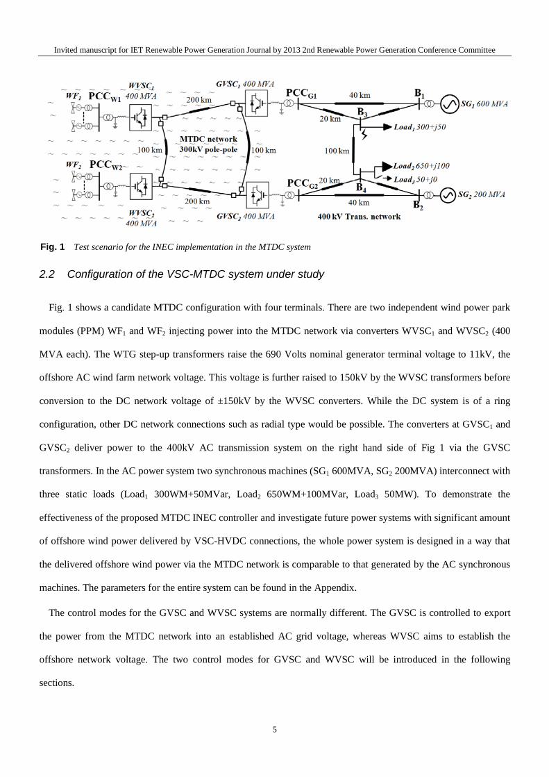
2.2 Configuration of the VSC-MTDC system under study
Fig. 1 shows a candidate MTDC configuration with four terminals. There are two independent wind power park
modules (PPM) WF1 and WF2 injecting power into the MTDC network via converters WVSC1 and WVSC2 (400
MVA each). The WTG step-up transformers raise the 690 Volts nominal generator terminal voltage to 11kV, the
offshore AC wind farm network voltage. This voltage is further raised to 150kV by the WVSC transformers before
conversion to the DC network voltage of ±150kV by the WVSC converters. While the DC system is of a ring
configuration, other DC network connections such as radial type would be possible. The converters at GVSC1 and
GVSC2 deliver power to the 400kV AC transmission system on the right hand side of Fig 1 via the GVSC
transformers. In the AC power system two synchronous machines (SG1 600MVA, SG2 200MVA) interconnect with
three static loads (Load1 300WM+50MVar, Load2 650WM+100MVar, Load3 50MW). To demonstrate the
effectiveness of the proposed MTDC INEC controller and investigate future power systems with significant amount
of offshore wind power delivered by VSC-HVDC connections, the whole power system is designed in a way that
the delivered offshore wind power via the MTDC network is comparable to that generated by the AC synchronous
machines. The parameters for the entire system can be found in the Appendix.
The control modes for the GVSC and WVSC systems are normally different. The GVSC is controlled to export
the power from the MTDC network into an established AC grid voltage, whereas WVSC aims to establish the
offshore network voltage. The two control modes for GVSC and WVSC will be introduced in the following
sections.
Fig. 1 Test scenario for the INEC implementation in the MTDC system
5
Invited manuscript for IET Renewable Power Generation Journal by 2013 2nd Renewable Power Generation Conference Committee
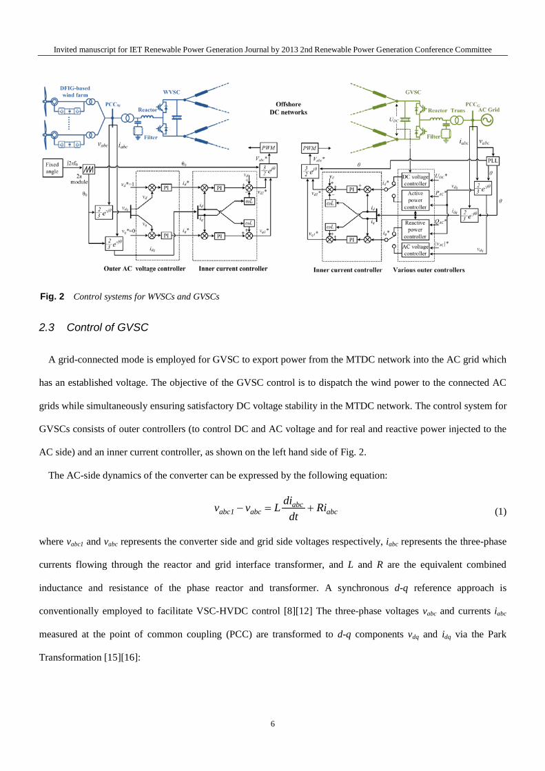
2.3 Control of GVSC
A grid-connected mode is employed for GVSC to export power from the MTDC network into the AC grid which
has an established voltage. The objective of the GVSC control is to dispatch the wind power to the connected AC
grids while simultaneously ensuring satisfactory DC voltage stability in the MTDC network. The control system for
GVSCs consists of outer controllers (to control DC and AC voltage and for real and reactive power injected to the
AC side) and an inner current controller, as shown on the left hand side of Fig. 2.
The AC-side dynamics of the converter can be expressed by the following equation:
abcabc1 abc abc
div v L Ridt
− = + (1)
where vabc1 and vabc represents the converter side and grid side voltages respectively, iabc represents the three-phase
currents flowing through the reactor and grid interface transformer, and L and R are the equivalent combined
inductance and resistance of the phase reactor and transformer. A synchronous d-q reference approach is
conventionally employed to facilitate VSC-HVDC control [8][12] The three-phase voltages vabc and currents iabc
measured at the point of common coupling (PCC) are transformed to d-q components vdq and idq via the Park
Transformation [15][16]:
Fig. 2 Control systems for WVSCs and GVSCs
6
Invited manuscript for IET Renewable Power Generation Journal by 2013 2nd Renewable Power Generation Conference Committee
)( 3
232
32
c
j
b
j
atj
qddq vevevjejvvvππω −− ++=+=
(2)
)( 32
32
32
c
j
b
j
atj
qddq ieieijejiiiππω −− ++=+= (3)
A phase-locked-loop (PLL) block [11] is used to synchronise the HVDC converter to the grid voltage at the PCC
and to align the voltage vector of the grid with the d-axis (when the network voltage at the PCC remains constant
and balanced, vq=0). In the synchronous d-q reference frame, the dynamics of the VSC in (1) can be expressed as:
1d
d d q ddiv L Ri Li vdt
ω= + − + (4)
1q
q q ddi
v L Ri Lidt
ω= + + (5)
where vd1 and vq1 are the d-axis and q-axis converter side voltage vectors.
In order to track the reference currents id* and iq
*, the inner current control uses proportional-integral (PI)
controllers with feedback to regulate the current vectors id and iq as shown in Fig. 2. Therefore, the VSC voltage
vector references vd1* and vq1
* for the VSC are computed as follows:
* *1 ( )( )i
d p d d d q dkv k i i Ri Li vs
ω= + − + − + (6)
* *1 ( )( )i
q p q q q d qkv k i i Ri Li vs
ω= + − + + + (7)
where kp and ki are the PI controllers’ gains.
The initial gains for the PI controllers can be selected by analysing the VSC’s electrical characteristics,
considering the impedance of the phase reactor and the grid interface transformer using Laplace manipulation [18].
However, the final gains must be properly tuned to ensure that satisfactory performance is achieved over the entire
system operating conditions, which must be considered to include both AC and DC network faults [19]. The
voltage vector references vd1* and vq1
* are transformed to a three-phase value vabc1* for pulse width modulation
(PWM) to produce the desired converter three-phase voltage. A double tuned AC shunt filter, tuned at the 27th and
54th harmonics in this case (1st and 2nd order of 1.35kHz VSC switching frequency), is installed between the phase
interfacing reactor and transformer, with the phase interfacing reactor and converter transformer forming part of the
7
Invited manuscript for IET Renewable Power Generation Journal by 2013 2nd Renewable Power Generation Conference Committee
filtering network that filters high frequency harmonics.
The outer controllers, as illustrated on the right hand side of Fig. 2, are used to compute the reference current id*
based on an active power or DC voltage reference, and iq* is computed based on reactive power or grid AC voltage
amplitude.
2.4 Control of WVSC
An island control mode is adapted for the WVSC to establish the offshore network voltage (in contrast to the
GSVCs where the voltage of the system being supplied is already established). When the MTDC network is used to
connect wind farms, the WVSCs act to set up a “stiff” AC bus with constant voltage and frequency to allow all
individual WTGs to synchronise to the wind farm AC system, and transmit their generated power into the wind
farm’s AC grid, as shown in Fig. 2. The control of the wind farm is based on maximum power point tracking
(MPPT), which is based upon wind power-versus-turbine speed characteristics at different wind speeds [8]-[12].
Various island modes for VSC control system are discussed in [13], and theoretically they are all suitable for
MTDC WVSC control. The most distinct feature of a WVSC’s control loops, from the perspective of operating in
grid-connected mode when connected to a wind-farm’s AC system, is that the angle used for abc-dq and dq-abc
transformations is obtained from a signal oscillator with a fixed modulation rate, as shown in the saw-tooth block
on the left hand side of Fig. 2, rather than from a phase-locked loop dynamically tracking the established grid
frequency. This oscillator sets the frequency of the WVSC’s voltage waveforms so the offshore electrical frequency
is regulated (e.g. at 50/60 Hz). As illustrated in Fig.2, the d-axis voltage vector vd, representing offshore voltage
magnitude, is controlled at 1 pu, whereas q-axis voltage vector vq, representing any offshore voltage phase angle
change, is regulated at 0 so that offshore network frequency remains constant. As long as the frequency and AC
voltage magnitude are maintained at constant levels, the power generated by the wind farm is automatically
absorbed via the WVSC and transferred to the DC link [12].
In [8]-[12] and [14], a single-loop control approach to control of voltage in an islanded mode, in the absence of
any inner current controller, is adopted for the integration of a doubly-fed-induction-generator-based (DFIG) wind
farm to the offshore AC network. However, a shortcoming of this control approach, as discussed in [13], is that it
8
Invited manuscript for IET Renewable Power Generation Journal by 2013 2nd Renewable Power Generation Conference Committee
has no explicit current control capabilities to limit large transient currents, due to the absence of inner current
control loops, and this could lead to unnecessary stress on the converters.
Inner current control loops, similar to that of the GVSC controllers, is therefore adoped in the WVSC as shown
in Fig. 2 to provide a secure means of current control for the WVSC operation (also referred as “nested voltage and
current control-loops” in [13]). By regulating the AC voltage amplitude component vd with a target value of 1 pu
and the phase angle voltage component vq with a target of 0, the WVSC can act as a “stiff” voltage source and idq*
for the inner current control is generated. A constant phase angle θ0 is provided for the Park and inverse Park
transformations by a fixed PLL which uses grid frequency f0 (e.g. 50 Hz) as a constant input, as illustrated in Fig. 2.
3 Inertia emulation controller for MTDC VSCs
In order to achieve an inertial contribution to the onshore AC system from the MTDC VSC converter, a generic
inertia emulation controller has been introduced to emulate inertia energy delivery to the AC side of the converter
by regulating the DC voltage and hence controlling the effective energy delivery from the DC capacitor(s) on the
DC side of the converter. An inertia emulation controller of a similar concept was developed in [11], but this was
designed for point-point VSC-HVDC applications. There is a concern that the DC capacitance used for
conventional point-point HVDC systems may be too small to generate large enough inertia time constants for
MTDC applications and hence additional DC capacitors may be required. With respect to a VSC-MTDC, a larger
number of DC capacitors for each VSC terminal within the MTDC system compared to point-point HVDC can be
exploited as temporary energy storage for inertia emulation; therefore there is an inherent advantage of applying
the controller as developed in [11] for VSC-MTDC systems. This section will introduce the controller design and
analyse the value C for the MTDC DC capacitance with regards to the desired emulated inertia time constant HVSC
and the degree of DC voltage variation that is reuiqred to deliver this value of inertia.
3.1 Derivation process of the INEC expression
For a sudden mismatch between the mechanical and electrical power in a synchronous machine, its inertia time
constant has a significant effect on the rate of change of its rotor angular speed. Taking all the machines in a power
system as a whole, the total aggregate machine inertia has a critical impact on the rate of change of grid frequency
(ROCOF) during large frequency disturbances. This can be expressed as:
9
Invited manuscript for IET Renewable Power Generation Journal by 2013 2nd Renewable Power Generation Conference Committee
10
2 PPPdtdfH
f EM ∆=−= (pu) (8)
where f0 is the nominal frequency in Hz, H is the inertia time constant in sec, PM is the mechanical power in pu, PE
is the electrical power in pu and ΔP1 is the kinetic power absorbed by or released from the inertia of the machine
during a speed change (in pu).
A dynamic power equation similar to (8) can be found for a VSC with a DC capacitor. When there is a DC
voltage variation on the capacitor, the VSC active power output is changed and how much the active power change
depends on VSC’s DC capacitance. The AC/DC power dynamics can be obtained using the following equation:
2VSCS
PPPdt
dVCNVoutin
dcdc ∆=−= (pu) (9)
where N represents the total number of capacitors in HVDC or MTDC systems, SVSC represents the VA rating of
the VSC, C represents the MTDC converter terminal capacitance which is the sum of the converter capacitor's
capacitance CVSC and the line capacitance averaged to each VSC terminal CL_dc/N, Pin is VSC power input to the
two capacitors in pu, Pout is the VSC power output in pu, and ΔP2 is the dynamic electrostatic power stored or
released across both capacitors in pu.
A change of AC grid frequency is indicative of a system power imbalance as expressed in (8). For a VSC with
DC capacitors, a change of DC voltage level reflects a change in the active power being supplied by the VSC
converter as observed in (9). To equate (8) with (9), a direct link between VSC DC voltage and AC grid frequency
can be derived through (10) to (13) together with the emulated inertia time constant HVSC:
dtdVC
SNV
dtdfH
fdc
VSC
dcVSC =
0
2 (10)
Integrating both sides of (10) yields (11) below. This process cancels df/dt and dVdc/dt on the two sides into (11):
dcVSC
dcVSC VdS
NCVdff
H∫∫ =
0
2 (11)
0VSC
2
0
K2S
2+= dcVSC NCV
ffH
(12)
VSC
dcVSC S
NCVHK2
22
00 −= (13)
10
Invited manuscript for IET Renewable Power Generation Journal by 2013 2nd Renewable Power Generation Conference Committee
The constant K0 is the constant of integration which is calculated according to the specified values of HVSC, total
combined DC capacitance NC, the nominal DC voltage Vdc0 and the converter power rating SVSC.
In order to emulate a specific inertia time constant HVSC, equation (12) implies that the DC voltage level in the
VSC-HVDC link must vary according to the AC network frequency, although the variation will be non-linear. A
large value of HVSC will require a correspondingly large variation in DC voltage and this must be considered in the
design of the VSC-HVDC system. The relationship between the emulated VSC inertia time constants and DC
voltage variations is derived in [11] as follows:
0
2
0
20
2
112
ff
VV
SNCV
HDC
DC
VSC
DC
VSC ∆
−
+
∆
= (14)
3.2 INEC implementation into MTDC systems
In order to enable an MTDC converter to provide an inertial response to AC grid transients, the overall DC
voltage is not expected to be fixed because of the INEC control action on the MTDC network voltage. Because of
the possible interaction on the DC network between converters, the MTDC should have only one grid side VSC
(GVSC) implemented with the INEC in its DC voltage regulator. The DC voltage reference VDC* generated for the
DC voltage regulating terminal is derived from (12) and (13):
*1
0
4 VSC VSCDC
S HV f KNCf
= ⋅ −
(15)
where the constant 201
4DC
VSCVSC VNC
HSK −= .
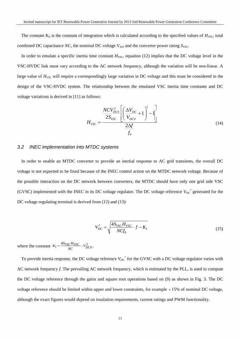
To provide inertia response, the DC voltage reference VDC* for the GVSC with a DC voltage regulator varies with
AC network frequency f. The prevailing AC network frequency, which is estimated by the PLL, is used to compute
the DC voltage reference through the gains and square root operations based on (9) as shown in Fig. 3. The DC
voltage reference should be limited within upper and lower constraints, for example ± 15% of nominal DC voltage,
although the exact figures would depend on insulation requirements, current ratings and PWM functionality.
11
Invited manuscript for IET Renewable Power Generation Journal by 2013 2nd Renewable Power Generation Conference Committee
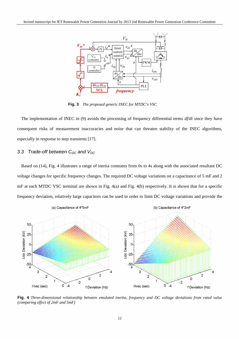
Fig. 4 Three-dimensional relationship between emulated inertia, frequency and DC voltage deviations from rated value (comparing effect of 2mF and 5mF)
The implementation of INEC in (9) avoids the processing of frequency differential terms df/dt since they have
consequent risks of measurement inaccuracies and noise that can threaten stability of the INEC algorithms,
especially in response to step transients [17].
3.3 Trade-off between CDC and VDC
Based on (14), Fig. 4 illustrates a range of inertia constants from 0s to 4s along with the associated resultant DC
voltage changes for specific frequency changes. The required DC voltage variations on a capacitance of 5 mF and 2
mF at each MTDC VSC terminal are shown in Fig. 4(a) and Fig. 4(b) respectively. It is shown that for a specific
frequency deviation, relatively large capacitors can be used in order to limit DC voltage variations and provide the
Fig. 3 The proposed generic INEC for MTDC’s VSC
12
Invited manuscript for IET Renewable Power Generation Journal by 2013 2nd Renewable Power Generation Conference Committee
desired emulated inertia time constants. The tradeoff between capacitor size and maximum allowable DC voltage
variation must be taken into account in the design and specification of the system.
4 Simulation results
Simulation scenarios as illustrated in Fig. 1 are carried out in Simulink/Matlab to validate the INEC for the
MTDC systems and verify the effectiveness of contributing emulated inertia responses. The four VSCs for the
MTDC system are rated at 400 MVA. All converter stations WVSC1,2 and GVSC1,2 are described using detailed
switch models of a two-level voltage source converter, with their AC side filters tuned to attenuate switching
frequency harmonics and their sidebands. The lines that form the DC network are modelled using nominal π
configuration with parameters presented in Table A, and this is sufficient considering the scope of this paper.
However, for DC fault studies, the use multiple π sections is necessary to avoid over-estimation of the DC fault
current (but this is outside of the scope of this paper).
On the offshore side, the two DFIG based WF1 and WF2 are simulated respectively as one lumped DFIG model
with its turbine aerodynamic model, drive train system, induction generator model and back-to-back PWM
conversion system. On the onshore side, the 600 MVA rated SG1 and 200 MVA rated SG2 are represented by the
seventh-order model with IEEE parameters [15]. Their inertia time constants are 3.3s and 3.2s, respectively. The
400 kV Transmission networks interconnect two MTDC GVSCs and two SG with passive load banks Load1,2,3,
with specific lengths as shown in Fig. 1 and impedance parameters as presented in Appendix Table B.
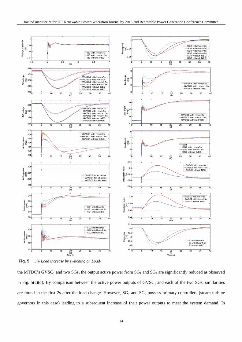
4.1 Load increase
Figs. 5 shows the simulation comparisons between GVSC1 with a DC voltage controller which regulates its node
DC voltage level constant at 301 kV (HVSC1=0), and the same GVSC1 with the INEC which emulates an inertia time
constant of HVSC1=3s and HVSC1=1.5s. The load increase is initiated by switching on Load3 of 50 MW, representing
5% of the total load. Fig. 5(a) illustrates the voltage change resulted by the sudden load increase, with minor
voltage drop of 0.02 pu observed. As shown in Fig. 5(b)(c), MTDC terminal DC voltage levels by the traditional
control remains constant for the sudden load change, whereas those equipped with INEC are controlled to drop. As
observed in Fig. 5(d), a rapid power increase from GVSC1 indicating its inertia contribution from the INEC action,
whereas GVSC1 with the traditional DC voltage controller remains the same. Due to the inertial interactions among
13
Invited manuscript for IET Renewable Power Generation Journal by 2013 2nd Renewable Power Generation Conference Committee
Fig. 5 5% Load increase by switching on Load3
the MTDC’s GVSC1 and two SGs, the output active power from SG1 and SG2 are significantly reduced as observed
in Fig. 5(c)(d). By comparison between the active power outputs of GVSC1 and each of the two SGs, similarities
are found in the first 2s after the load change. However, SG1 and SG2 possess primary controllers (steam turbine
governors in this case) leading to a subsequent increase of their power outputs to meet the system demand. In
14
Invited manuscript for IET Renewable Power Generation Journal by 2013 2nd Renewable Power Generation Conference Committee
contrast, GVSC1 provides a short-term “pure” inertial active power impulse using the energy stored in the MTDC
capacitors. The benefits of the inertia contribution from GVSC1 are evident from the rotor speed of each of the SGs
as shown in Fig. 5(h), the voltage and load angles (with respect to SG1’s electromotive force angle) of the GVSCs
and SGs as shown in Figs. 5(i)(j)(k) respectively, as well as the network frequency drop at busbar B3 as shown in
Fig. 5(n). Despite the short period of inertia contribution by the MTDC, it significantly improves the frequency
performance of the supplied AC multi-machine system.
Fig.5(l)(m) present the modulation indices for converter stations GVSC1 and GVSC2, and it can be observed that
the modulation indices of both converters are equally varied between 0.84 to 0.91 as the load is changed. Fig. 5(e)
shows that the active powers of WVSC1, WVSC2 and GVSC2 do not respond to the load increase. This verifies that
the INEC decouples disturbances from the onshore AC grid side to the offshore wind farm side, while still
contributing an emulated inertia; this is an attractive feature of the INEC. The INEC can of course also be applied
to GVSC2; this will be studied in Section 4.2 which relates to testing performance under fault conditions.
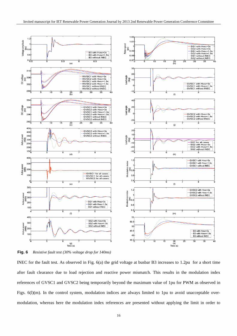
4.2 Fault study
Figs. 6 show the simulation results from fault studies with the INEC applied to GVSC2 (and with three separate
inertias of HVSC2=3s, 1.5s and 0). The fault is simulated at Busbar B3 as illustrated in Fig. 1, and has a duration of
140 ms before being cleared – in practice, fault clearance may be faster than this, but this duration has been chosen
to simulate worst case fault clearance conditions according to [10]. As described in [11], the restrained capability of
the INEC by solid faults due to the VSC current saturation, in this case only the resistive fault which results in a 0.5
pu voltage amplitude drop at B3 as shown in Fig. 6(a), is studied.
It is clearly shown in Fig. 6(b)(c) that DC voltage levels for each of the four VSC nodes are not affected by the
fault when conventional non-inertial control schemes are applied, whereas the DC voltage level changes for those
results where GVSC2 is equipped with INEC and HVSC2=3s and HVSC=1.5s as shown in Fig. 6. Through the active
power interactions between GVSC2 and two SGs as shown in Figs. 6(d)(f)(g) respectively, the rotor speed
variations and frequency variations at busbar B3, as illustrated in Fig. 6(h) and (n) respectively, are significantly
damped and postponed by larger emulated inertia provided by GVSC2. The small load angle variations for the case
with HVSC2=3s than those with HVSC2=1.5s and 0, observed in Figs. 6(i)(j)(k) indicating the stabilising effect of the
15
Invited manuscript for IET Renewable Power Generation Journal by 2013 2nd Renewable Power Generation Conference Committee
Fig. 6 Resistive fault test (30% voltage drop for 140ms)
INEC for the fault test. As observed in Fig. 6(a) the grid voltage at busbar B3 increases to 1.2pu for a short time
after fault clearance due to load rejection and reactive power mismatch. This results in the modulation index
references of GVSC1 and GVSC2 being temporarily beyond the maximum value of 1pu for PWM as observed in
Figs. 6(l)(m). In the control system, modulation indices are always limited to 1pu to avoid unacceptable over-
modulation, whereas here the modulation index references are presented without applying the limit in order to
16
Invited manuscript for IET Renewable Power Generation Journal by 2013 2nd Renewable Power Generation Conference Committee
clearly show the degree of INEC intended modulations. Throughout the whole simulation process presented in Fig.
6, it appears that the GVSCs with the INEC help to minimise the system disturbances arising from the fault. The
active power of WVSC1, WVSC2 and GVSC1 remain the same for three cases, as shown in Fig. 6(e).
5 Conclusion
This paper has described a generic inertia emulation controller (INEC) for multi-terminal HVDC (MTDC)
system application, as a follow-up activity from its implementation on a point-to-point HVDC system, as presented
in [11]. The INEC allows a MTDC grid side converter to contribute an inertial response, by varying DC voltage
levels to access and exchange the electro-static energy stored in DC link capacitors with an AC grid. The system
does not require any modification to the MTDC hardware. The presented simulation results have shown that the
INEC possesses the following features:
i) It facilitates damping of synchronous generators’ rotor speed variations during system disturbances (e.g.
demand changes, temporary faults) by supplying and absorbing compensating energy to and from the AC
system as required;
ii) Power system frequency deviations as well as busbar load angle deviations during system disturbances are
effectively stabilized by the INEC;
iii) The INEC retains the decoupling feature of VSCs, which isolates AC grid disturbances from offshore weak
AC power systems used for wind farm energy collection.
The study scenario assumes a network with comparable grid and off-shore generation capacity to allow the
effectiveness of the inertia contribution control concept on VSC-MTDC system to be assessed. Future work will be
required to explore how the INEC can be implemented on existing systems in more detail, and how the operation of
the INEC can be perfected under conditions where there are high grid voltage harmonics and under unbalanced
conditions.
17
Invited manuscript for IET Renewable Power Generation Journal by 2013 2nd Renewable Power Generation Conference Committee
6 References
[1] Lalor, G., Mullane, A., O’ Malley, M.: ‘Frequency control and wind turbine technologies’, IEEE Trans. Power.
Syst., 2005, 20, (4), pp. 1905–1913
[2] Conroy, J., Watson, R.: ‘Frequency response capability of full converter wind turbine generators in comparison
to conventional generation’, IEEE Trans. Power Syst., 2008, 23, (2), pp. 649–656
[3] Mokadem, M. E., Courtecuisse, V., Saudemont, C., Robyns, B., Deuse, J.: ‘Experimental study of variable
speed wind generator contribution to primary frequency control’, Renew. Energy, 2009, 34, pp. 833–844
[4] Kayikci, M.; Milanovic, J.V.: ‘Dynamic Contribution of DFIG-Based Wind Plants to System Frequency
Disturbances’, IEEE Trans. on Power Syst., 2009, 24, (2), pp. 859-867
[5] Miao, Z., Fan, L., Osborn, D., Yuvarajan, S.: ‘Wind farms with HVdc delivery in inertial response and primary
frequency control’, IEEE Trans. Energy Convers., 2010, 25, (4), pp. 1171-1178
[6] Phulpin, Y.: ‘Communication-Free Inertia and Frequency Control for Wind Generators Connected by an
HVDC-Link’, IEEE Trans. Power Syst., 2012, 27, (2), pp. 1136-1137
[7] Zhu, J., Booth, C.D.: ‘Future multi-terminal HVDC transmission systems using Voltage source converters’.
Proc. Int. Univ. Power Eng. Conf., Cardiff, U.K., 2010, pp. 1-6
[8] Lu, W.X., Ooi, B.T.: ‘Multiterminal LVDC system for optimal acquisition of power in wind-farm using
induction generators’, IEEE Trans. on Power Electron., 2002, 17, (4), pp. 558-563
[9] Jovcic, D., Strachan, N.: ‘Offshore wind farm with centralised power conversion and DC interconnection’, IET
Gen., Trans. & Dist., 2009, 3, (6), pp. 586-595
[10] National Grid UK: 'The GB Grid code', http://www2.nationalgrid.com/UK/Industry-
information/Electricity-codes/Grid-code/The-Grid-code/
[11] Zhu, J., Booth, C.D., Adam, G.P., Roscoe, A.J., Bright, C.G.: ‘Inertia Emulation Control Strategy for VSC-
HVDC Transmission Systems’, IEEE Trans. on Power Syst., 2013, 28, (2), pp. 1277-1287
[12] Xu, L., Yao, L.Z.; Sasse, C.: ‘Grid Integration of Large DFIG-Based Wind Farms Using VSC
Transmission’, IEEE Trans. on Power Syst., 2007, 22, (3), pp. 976-984
18
Invited manuscript for IET Renewable Power Generation Journal by 2013 2nd Renewable Power Generation Conference Committee
[13] Green, T.C., Prodanovic, M.: ‘Control of inverter-based micro-grids’, Electric Power Systems Research,
2007, 77, pp. 1204-1213
[14] Feltes, C., Wrede, H., Koch, F., Erlich, I.: ‘Fault ride-through of DFIG-based wind farms connected to the
grid through VSC-based HVDC link’. PSCC 16th Power System Computation Conf., 2008, pp. 1-7
[15] Anderson, P., Fouad, A.A.: ‘Power System Control and Stability’, The Iowa State Univerity Press, 1977
[16] Novotny, D. W., Lipo, T. A.: ‘Vector Control and Dynamics of AC Drives’, Clarendon Press, 1996
[17] Bennett, S., ‘Development of the PID controller’, IEEE Trans. Control Syst., 1993, 13, (6), pp. 58–62
[18] Adam, G. P., Williams, B. W., "Half and Full-Bridge Modular Multilevel Converter Models for
Simulations of Full-Scale HVDC Links and Multi-terminal DC grids," Accepted for publication in a future
issue of IEEE Journal of Emerging and Selected Topics in Power Electron., 2014
[19] Adam, G. P.: ‘Voltage Source Converter: Modulation, Control and Applications in Power Systems’,
CreativeSpace, 2013
19
Invited manuscript for IET Renewable Power Generation Journal by 2013 2nd Renewable Power Generation Conference Committee
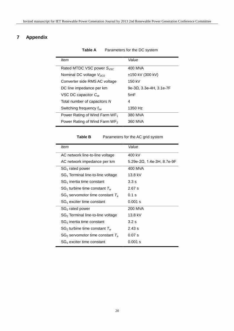
7 Appendix
Table A Parameters for the DC system
Item Value
Rated MTDC VSC power SVSC 400 MVA Nominal DC voltage VDC0 ±150 kV (300 kV)
Converter side RMS AC voltage
150 kV
DC line impedance per km 9e-3Ω, 3.3e-4H, 3.1e-7F
VSC DC capacitor Cdc 5mF
Total number of capacitors N 4
Switching frequency fsw 1350 Hz
Power Rating of Wind Farm WF1 380 MVA Power Rating of Wind Farm WF2 360 MVA
Table B Parameters for the AC grid system
Item Value
AC network line-to-line voltage 400 kV AC network impedance per km 5.29e-2Ω, 1.4e-3H, 8.7e-9F
SG1 rated power 400 MVA SG1 Terminal line-to-line voltage 13.8 kV
SG1 inertia time constant 3.3 s
SG1 turbine time constant Tw 2.67 s
SG1 servomotor time constant Ta 0.1 s
SG1 exciter time constant 0.001 s
SG2 rated power 200 MVA SG2 Terminal line-to-line voltage 13.8 kV
SG2 inertia time constant 3.2 s
SG2 turbine time constant Tw 2.43 s
SG2 servomotor time constant Ta 0.07 s
SG2 exciter time constant 0.001 s
20
Invited manuscript for IET Renewable Power Generation Journal by 2013 2nd Renewable Power Generation Conference Committee
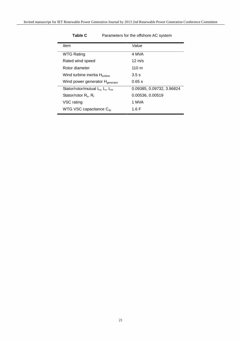
Table C Parameters for the offshore AC system
Item Value
WTG Rating 4 MVA Rated wind speed 12 m/s
Rotor diameter 110 m
Wind turbine inertia Hturbine 3.5 s Wind power generator Hgenerator 0.65 s
Stator/rotor/mutual Ls, Lr, Lm 0.09385, 0.09732, 3.96824 Stator/rotor Rs, Rr 0.00536, 0.00519
VSC rating 1 MVA
WTG VSC capacitance Cdc 1.6 F
21