Embed Size (px)
Citation preview

Aalborg Universitet
Measurements of Head-Related Transfer Functions (HTFs) on 40 Human Subjects
Larsen, Kim Alan; Hundebøll, Jørn Vagn; Hammershøi, Dorte; Møller, Henrik
Published in:Proceedings of Nordic Acoustical Meeting, NAM '92
Publication date:1992
Link to publication from Aalborg University
Citation for published version (APA):Larsen, K. A., Hundebøll, J. V., Hammershøi, D., & Møller, H. (1992). Measurements of Head-Related TransferFunctions (HTFs) on 40 Human Subjects. In Proceedings of Nordic Acoustical Meeting, NAM '92 (pp. 307-312).Norway.
General rightsCopyright and moral rights for the publications made accessible in the public portal are retained by the authors and/or other copyright ownersand it is a condition of accessing publications that users recognise and abide by the legal requirements associated with these rights.
? Users may download and print one copy of any publication from the public portal for the purpose of private study or research. ? You may not further distribute the material or use it for any profit-making activity or commercial gain ? You may freely distribute the URL identifying the publication in the public portal ?
Take down policyIf you believe that this document breaches copyright please contact us at [email protected] providing details, and we will remove access tothe work immediately and investigate your claim.
Downloaded from vbn.aau.dk on: April 25, 2017

307
NAM'92 JUNE22-24
OSLO, NORWAY
Proceedings edited by
Mike Newman
MEASUREMENTS OF HEAD-RELATED TRANSFER FUNCTIONS (HTFs) . ON 40 HUMAN SUBJECTS
Kim Alan Larsen, Jsrn Vagn Hundebsll Perceptive Acoustics A/S Fredrik Bajersvej 7 DK-9220 Aalborg 0 Denmark
Introduction
Dorte Hammershsl, Henrik M"ller Institute for Electronic Systems, Aalborg University Fredrik Bajersvej 7 DK-9220 Aalborg 0 Denmark
A Head-related Transfer Function (HTF) is a transfer function that - for a certain angle of incidence - describes the sound transmission from a sound source in a free field to a point in the ear canal of a human subject. Knowledge of HTFs from a large population is essential for 1) design and evaluation of artificial heads for binaural recordings, 2) computer synthesis of binaural signals (virtual environment applications and auralization in room modelling systems), and 3) determining diffuse field to free field corrections of hearing thresholds and equal loudness contours.
The major interest in this investigation is the use in binaural recording technique. This technique is based on the following idea. The input to the hearing consists of two signals: sound pressures at each of the eardrums. If these are recorded in the ears of a listener and reproduced exactly as they were (usually through headphones), then the complete auditive experience is assumed to be reproduced, including timbre and spatial aspects. During recording the listener is normally replaced by an artificial head that replicates the acoustical properties of an average human head.
A thorough description of the HTF measurements is given in Hammersh0i et al. [1] whereas this paper only describes the most important aspects. Among these is the choice of the point in the ear canal where the recording is made - the reference point. In this investigation the choice of reference point is based on a model described by M01ler [2] and verified by Hammersh0i & M0ller [3]. The model is seen in Figure 1.

Zeor canal
308
Zradlotlon
transmission Un,
2,ar canal
Figure 1. Sound transmission through the external ear; sketch of the anatomy and an analouge model, as described by M0ller [2].
The sound transmission is divided into a part that creates all directional cues, and a part that is independent of direction. The directional dependent part consists of the transformation from the free field to the Thevenin sound pressure p2. p2 does not exist in the listening situation but if an earplug is placed with its outer end flushing with the ear canal entrance p2 can be found outside the earplug.
In the non-directional part p2 is the sound source, and the source impedance is the radiation impedance seen from the ear canal, Zradiation· The sound pressure at the entrance to the open ear canal is denoted p3. The ear canal acts like an acoustical transmission line terminated by the eardrum impedance, Zeardrum• and the sound pressure at the eardrum is denoted p4.
p2, p3 and p4 can all be used for binaural recordings. However, p2 is the most convenient to use, as it does not require insertion of microphones deeply in the ear canals. Furthermore, p2 includes the directional information and in addition avoids individual differences caused by the ear canal. With a reference sound pressure p1 defined as the sound pressure at the position in the middle of the subject's head but with the subject absent, the choice of HTF is therefore:
P2 sound pressure at entrance to the blocked ear canal HTF = - = ____ ....:__ ________________ _ P1 sound pressure in the middle of the head, without the listener
M0ller showed elsewhere [2] how the correct total sound transmission in a binaural system is especially simple to achieve, if the reproduction involves a pressure division similar to the one seen between Zear canal and Zradiation during recording. To evaluate this the pressure division [P3/P2], is measured, yet only for a few source directions assuming directional independence. In M0ller et al. [4] these data are used for comparison with measurements of the pressure division in the playback situation.
Method
The microphone techniques used for measuring p2 and p3 are sketched in Figure 2.
·309
Ear canal Eor conol
-~ ·, ,
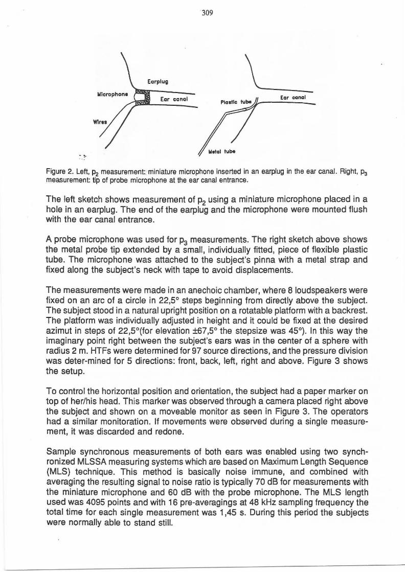
Figure 2. Left, p2 measurement:. miniature microphone inserted in an earplug in the ear canal. Right, p3 measurement: tip of probe microphone at the ear canal entrance.
The left sketch shows measurement of p2 using a miniature microphone placed in a hole in an earplug. The end of the earplug and the microphone were mounted flush with the ear canal entrance.
A probe microphone was used for p3 measurements. The right sketch above shows the metal probe tip extended by a small, individually fitted, piece of flexible plastic tube. The microphone was attached to the subject's pinna with a metal strap and fixed along the subject's neck with tape to avoid displacements.
The measurements were made in an anechoic chamber, where 8 loudspeakers were fixed on an arc of a circle in 22,5° steps beginning from directly above the subject. The subject stood in a natural upright position on a rotatable platform with a backrest. The platform was individually adjusted in height and it could be fixed at the desired azimut in steps of 22,5°(for elevation ±67,5° the stepsize was 45°). In this way the imaginary point right between the subject's ears was in the center of a sphere with radius 2 m. HTFs were determined for 97 source directions, and the pressure division was deter-mined for 5 directions: front, back, left, right and above. Figure 3 shows the setup.
To control the horizontal position and orientation, the subject had a paper marker on top of her/his head. This marker was observed through a camera placed right above the subject and shown on a moveable monitor as seen in Figure 3. The operators had a similar monitoration. If movements were observed during a single measurement, it was discarded and redone.
Sample synchronous measurements of both ears was enabled using two synchronized MLSSA measuring systems which are based on Maximum Length Sequence (MLS) technique. This method is basically noise immune, and combined with averaging the resulting signal to noise ratio is typically 70 dB for measurements with the miniature microphone and 60 dB with the probe microphone. The MLS length used was 4095 points and with 16 pre-averagings at 48 kHz sampling frequency the total time for each single measurement was 1,45 s. During this period the subjects were normally able to stand still.

310
Figure 3. Free field setup in the anechoic chamber. Note that for phototechnic reasons the monitor is slightly closer to the subject than during measurements.
HTFs and pressure division were determined by Fourier transformation of the impulse responses measured, followed by complex division in the frequency domain. By this division the ~easuring equipment cancels out. The Head-related Impulse Responses (H/Rs [p1~p;J), often required for computer synthesis of binaural signals, are obtained by inverse Fourier Transformation of the lowpass filtered HTFs.
Results
Measurements were carried out on 40 human subjects, 18 females and 22 males, all with controlled normal hearing.
An example of HTF and HIR for one subject with sound incidence from left is shown in Figure 4. As expected, the signal at the right ear (dashed line) is attenuated compared to the right ear, especially at high frequencies. This is also seen from the HI Rs shown to the right. The left HIR is non-causal, because this ear is closer to the source than the measuring point of p1•

311
Amplitude (dB)
O dB .. ......... ... -· ~·- -..... .. ·· ··, , ··· ·-··--· -.. ,,' ' \ I I
llOdB '/\,\ ,,, ~ \
I ,. I
'
Amplitude (Pa/Pa)
" -.. ---·--·' ,_ .. ,,,_'.----···
100 1k 10k (Hz) 0 1 (ms)
Figure 4. HTF and HIR for one subject, sound from left. Right ear is the dashed line.
The pressure division is shown in Figure 5. The upper set of curves shows the left ear of one subject with sound from the 5 directions measured. As it is seen the pressure division is similar for all directions and thus direction independent as assumed. The lower set of curves shows the pressure division for 12 subjects with sound from above. A large inter-individual variation is seen from about 8 kHz. p3 will reflect the individual variation in HTF as well as the individual variation in the pressure division. This means that [P 3/P 1] is expected to show larger variation than [P,)P 1] .
Amplitude (dB)
................ ~... " ... · ....... ·:-.... ·... · ... ; .. .... ... ~.. ... . . . . . . . . . . . . . . . .. .. . ... : " .. · .... ·. . . . ... ~ . ·:-........ ........ :, .... .
·······-···· ··········· ········· ·· . . .. . . . . . - .
················1···············:·····:···=···: .. : .. :··:, ......................... :······: .... .:. ... : .. ~ .. :··:·.:. ......... ... .:. ....... . lodB . . . . . . . . . . . . . . . . . . . . . . . . . . . . . . . . . . . . . . . . . . . . . . . . . . . . . . . . . .
......... ... ·- · ....... ~- ... '. ~-' ... ; ... ; ... ; .. ~-. ; .. ; .. .... . ' .. ...... ; ..... .... : ...... : .... ~ .... ; ... : .. ; .. ; . ;. . ..... .. .. . .. ; ........ .
... · ; .. :.: ..... .. _ ....... : ... ..... .
. .
[P,IP~ ·--············t-- --···\····--('··(·(·(t-(·······--···--··(·····/·--·(··:··/t··:--(········-- ··t--······ . . . . . . . . . . . . . . .
OdB ... .... ..... :
. . . . ... . . . . . . .. . . .. . . . . ~-· ....... ~ ...... .;: ..... ; ... ; ... ; ... : .. ; .. ; ............... -~ ........ -~ .. .
. . . .. . . . .. . . .... .... ... ~- · ....... ~- ...... ;. .... ; ... ~ ... ; ... : ... : .. ; .. ............. ·:· ... .... .; .. . .. . ·!· .... ; ... ,:, .. ; ... : . ·. :, ..
. . . . . . . . . . . . . . . . . . . . . . . . . . . . . . . . . . .
100 1k 10k (Hz)
Figure 5. Illustration of the pressure division. Upper set: left ear of one subject, 5 directions. Lower set: left ear of 12 subjects, sound from above.

312
This is exactly seen from Figure 6, where both [P,JP1] and [P:JP1] are shown_forthe left ear of the same 12 subjects: Variations for [P;IP1] are seen but they are smaller and they appear at higher frequencies than for [P 3/P 1].
[P3'P1]
O dB
Amplitude (dB)
. . . . . . ... . .. ............... : ......... : ...... : ..... : ... : ... : .. :.: .. : ................ : .. .............. : .... : .... : ... : .. : .. :.: ......... . ... ..... ....... . . . . . . . . . . . . ..... .
... . . . . . .
. .
·············110· dB··: .. · .. :···:· .. :··: .: .. : ................ : ......... : ...... : .... r ... : ... : .. : .. :·:··· .. ....... ... . .. . .. .. ... ~- ... . . ~-.... ! .. . ~-- -~- -~-· :··: .... . ... ....... . , .. . . .. ···:. ·-.. ·:· .. -~· -··: . . -~-.: . ·:. ·.
. .. ..... ............. _ .. .... .. .. · . . · . . . . . . .
. . . . . . . . . . .
. . ..... . . . . .. .... ·: ........ ·: ..... ·:··. ·-:- .. ·:·. ·~ · . :. ·: . '::' ... . . . . ... .. . ":' ....... .
. . . . . . . . . .. . . . . . . . . . .. ... . . . ·····. ~--....... ; ...... : ... ··=··· ~---~-- ~- -~--= ............ ····:···· .. -- ~- .... ·:··. ·-:-·. ·:. : .. ·':' ..... .......... ~- ....... . . . . . . . . . . . . . . . . . . ..
. . ... . . . . . . . . . ···············: .. ·······:· .. ···; ..... :···:···:··-=- ·~··:·"'"''"'""':·· ... ................ :-..... . ... \J.»'l'IWll~-·"""" . . . . . . . . . . . . . . . . . . . .. . . ._ , ............ · ................ · .... ,' ... · ... · ... . · .. · ........... ..... · ......... ~ ...... ~ .... ~ .... ; ... ~..... . .. . . . . . .
................ : ........ . . :. .. , ... : ..... : ..... : ... : .. . ;..; . .: ................. ; ......... ; . .... . ; ..... : .... ; ... : ... ; .. f . . : .••. ..•
. . . . . . . . . . . .
............... ·; ......... ~ ...... -~· .... :-... ~ ... : .. ·:·. ·: .. : ................ : ......... ~-..... : .... ·:· ... : ... :· .. :. ·:. ~-. . .. . . . . ... .. '\' .. ..... .
100 1k 10k (Hz)
Figure 6. Upper curves: HTFs for the left ear of 12 subjects, sound from above. Lower curves: [PfP1] for the left ear of the same subjects and same sound incidence direction.
Conclusion
A suitable technique for HTF measurements is developed. HTF data are obtained, sample synchronously measured on both ears of 40 human subjects, for 97 source directions covering a whole sphere. The reference point for the measurements is at the entrance to the blocked ear canal. Data indicate that this is a suitable point for binaural recordings as inter-individual variation caused by differences in the ear canal is avoided. This means that it is unnecessary to design artificial heads with ear canals.
References
[1 ]: Dorte Hammershoi, Henrik Meller, Michael Friis Sarensen, Kim Alan Larsen: Head-related Transfer Functions: Measurements on 24 Human Subjects. Audio Engineering Society Preprint no. 3289, 1992. [2): Henrik Maller. Fundamentals of binaural technology. To be published in Applied Acoustics (special issue on Auditive Virtual Environments), 1992. [3]: Dorte Hammershoi & Henrik Meller. Free-field sound transmission to the external ear; a model and some measurements. Fortschritte der Akustik - DAGA '91 , Bochum, pp. 473-476, 1991. [4]: Henrik Moller, Dorte Hammershei, Jorn Vagn Hundebell, Clemen Boje Jensen: Transfer Characteristics of Headphones. Audio Engineering Society Preprint no. 3290, 1992.