Embed Size (px)
Citation preview

RESOLUTION NO. 2009-228
A RESOLUTION OF THE CITY COUNCIL OF THE CITY OF ELK GROVEAUTHORIZING THE CITY MANAGER TO EXECUTE OPTIONS FOR EIGHT 40'
COMPRESSED NATURAL GAS (eNG) TRANSIT BUSES WITH NEW FLYER OFAMERICA NOT TO EXCEED $4 MILLION
WHEREAS, the City of Elk Grove has received $4 million in AmericanReinvestment and Recovery Act (ARRA) "stimulus" funds; and
WHEREAS, eight vehicles in the City's Transit fleet either meet or exceed thefederal guidelines for replacement; and
WHEREAS, Transit staff has identified valid contracts with assignable optionsand has successfully obtained options for 40' CNG buses from New Flyer; and
WHEREAS, the City's Transit System Manager and Fleet Manager will visit theNew Flyer factory in Winnipeg, Canada for pre-build inspections in accordance withFederal Transit Administration (FTA) Best Practices and the New Flyer factory inCrookston, MN following build and prior to delivery to inspect the vehicles and complete
WHEREAS, the procurement complies with Federal Transit Administrationprocurement practices and allows the City to meet the ARRA deadlines.
NOW, THEREFORE, BE IT RESOLVED that the City Council of the City of ElkGrove hereby authorizes the City Manager to execute options, substantially in the formattached hereto as Exhibit A, for eight 40' CNG transit buses with New Flyer of Americain an amount not to exceed $4 million.
?~a+-lt-(}~PATRICK HUME, MAYOR of theCITY OF ELK GROVE
PASSED AND ADOPTED by the City Council of the City of Elk Grove this 18th
day of November 2009.
ATTEST:
SUSAN J. BLACKSTON, CITY CLERK
APPROVED AS TO FORM:a.: (0~,/SUSAN COCHRAN, CITY ATTORNEY

EXHIBIT A
CONTRACT
NEW FLYER - CONSULTANT
THIS CONTRACT ("Contract") is made and entered into between City of Elk Grove, aMunicipal Corporation ("City") and New Flyer ("Consultant"), and hereby acknowledges theagreement entered into between New Flyer and San Bernardino on the Request for Proposaldated May 30, 2008 ("Agreement").
WHEREAS, the City has the authority to utilize cooperative purchasing agreements withother public agencies pursuant to the Elk Grove Municipal Code Chapter 3.42; and
WHEREAS, San Bernardino has procured desirable services with Consultant for thepurchase of eight (8) C40LFR buses.
1. Consultant has previously entered into an Agreement with San Bernardino, attachedhereto as Exhibit A and incorporated herein by this reference. The City and Consultant shall bebound by all terms and conditions of the Agreement, except as modified by this Contract. In theevent of any inconsistency between this Contract and the Agreement, this Contract shall control.
2. Technical Summary. Exhibit B contains the technical summary for the six bus optionsacquired from the San Bernardino Agreement.
3. Compensation.
A. The Consultant shall be paid upon acceptance by City for the actual fees, costsand expenses for the time and materials required and expended, and approved by the City, but inno event shall total compensation exceed Four Million Dollars and No Cents ($4,000,000.00),without City's prior written approval.

4. Indemnification. To the fullest extent permitted by law, Consultant shall indemnify,protect, defend, and hold harmless City, its officers, officials, agents, employees and volunteersfrom and against any and all claims, damages, demands, liability, costs, losses and expenses,including without limitation, court costs and reasonable attorneys' and expert witness fees,arising out of any failure to comply with applicable law, any injury to or death of any person(s),damage to property, loss of use of property, economic loss or otherwise arising out of theperformance of the work described herein, to the extent caused by a negligent act or negligentfailure to act, errors, omissions, recklessness or willful misconduct incident to the performanceof this Contract on the part of Consultant, except such loss or damage which was caused by thesole negligence, or willful misconduct of the City. The provisions of this section shall survivetermination or suspension of this Contract.
Risk of loss is borne by New Flyeruntil acceptarlce by City.
AGREED to this day of , 2009, by the parties as follows.
Approved as to form:
By: _Attorney for Consultant
Approved as to form:
Attest to:
Susan J. Blackston, City Clerk
CONSULTANT
By: _
CITY OF ELK GROVE
By:. _Laura S. Gill, City Manager

EXHIBIT A
RFP
Available in City Clerk's office for viewing.

Technical Summary For: SR-1337 SAN BERNARDINO, CA 27 X C40LFR Revision: C
Exhibit BI
Value Description (blank means unset)Model - JI1IcrtY ftoorCOKh.
Option' Description'1CJO.OO21 COACH LENGTH
1()().0()2d STRUCTURALMATERIAL(B),Structuf'III "..,.,- CIIrbonsteel.
10D-002f COACH STYLING (C).co.ctl atyIIng - LFR.~ IcrtY ftoor.
201.Q05 BUMPERS (B).Bumperl - frontand,.r Romeo Rim Help 'S' bIIIck3 piece, reIIranti-ride felIture.
201-015 1uW ET~.FRONT (B),FroniioN~ • a.ic _-up inc:otpol'Uci in cila&ia.
1203-005 AXLE,FRONT,MFR (B).Front.. - MA.N. VB-e5L, GAWR 14.770b., hub mount. greae seal6. Haklexautomltlc sIlIckIIdJUIter&. Bendbc Type20 brake cMmber&.
2Q3.«)5d SECUREMENTOF (B),SecuNment of tnke Hninga - by rlvet&.BRAKE LININGS
203-010 POWER STEERINGUNIT (B),Steering bale·~rdM110,power usiIIted, frllmemounted, geerr.uo 23:1.
203-011 SHOCKABSORBERS.FRONT
(A),Frontahocfc.,.,... - Konl. quantity 2.
2Q3.011b NEVER SEIZE (S).Never 5eIze - on all-..pension bolls.
FRT AXLE AND WHEELSPLASHAPRONS
(C).Front.. .00 wheeI.pah aprons • full widthjust forwardof ute and wheels. Also. two Jldditionll .prons.ft of the Wheels.
MAN. REARAXLE
REARAXLE GEAR OIL
(B).R.r DIe - MAN. 5.44:1,HP-1352-B.GAWR28,660 Ibs (13 t). hUb mount, oil..... Haldex.uto .ckIIdJ""', Mol Type30 brake chllrnbera. yokedrlwshllft connection.
~1Od SHOCKABSORBERS.REARREAR AXLE DRAINPLUGS
204-1<110 IRR AXLEAND WHEELSPLASHAPRONS
(B).R.r DIe andwheeI"'lIh aprons- t.&ic, three piecesbehind the ..and wheels. Note:for 60', basicIncludestwo piecesbehindcenter wheels.
2054108
1205-01Oe
TIRES
I
WHEELS
WHEEL BALANCING
(B).Ti~ • NF aupplilldMIchelin 305I70RJ22.5.
(A).WheeIs - AICOlI. 22.5"x8.25" polishedaluminum.
(S),WheeIbaJlIncing - all wheels.
POWER STEERINGHOSES
(N).FC510CD STEERINGBODXAND IN ENGINECOMPARTMENT. POWER STEERINGLINESAREROUTEDUNDERFLOOR
209-010 POWER STEERINGPUMP
(B).Power -..ring pump - bcMic (Luk) power steering pumpfor Cummins engines.
DIAGNOSTICFTGS.POWERSTEERING
(A),Power steering diagnoetlc fittings· at steering box.
219-001 ENGINE (C),Englne - Cummins ISL G CNG, t-clrlve.
219-OO5d ENGINE (A).Engine- CumminsISL G CNG. 280 horsepower with 900LBFT torque.HORSEPOWERITORQUE
(C).EIectric -.rter - Delco 39MT, 24 volt.
(B).Engineair cornJlAlSSOr - Wabco HD 18.7 used with Cummins engines. Turbo npirmecl.
(B).Engine fat idle - .. at 1000 RPM.
(C).Road speed - toproeci speed is governed. set. tISMf"H (10:5 KPH).
l2ag& 1 of Q4
(N),ALTERNATOR- EMP450 AMP, 24 VOLT
(A),Engine oil dlpstlc:k - stBticoil level Indicator.
SsStIAdaR:t, &-&15&, ASAVli/lb/&, C-CU&tOr:R 11'13f.200g
·219-OO5e ENGINE FAST IDLE
219-005g IRoADSP~~D
219-OO51l ENGINE AIRCOMPRESSOR
'219-OO5i STARTER,ELECTRIC
219-0051 ALTERNATOR
1219-OO5k ENGINE OIL DIPSTICK

Technical Summary For: SR-1337 SAN BERNARDINO, CA 27 X C40LFR
'OPtion# 'Description Value Description (blank means unset)219-005q BELT GUARD (C),Belt guards - both the engine pulley guard and the NC unit guard are hinged.
Revision: C
?19-005qa
L19-005t
219-005v
219-010
219-010b219-010d
219-010e
219-010f
219-010g
219-010q
219-010r
219-010v
219-025
219-025a
219-030
./"035
219-035a
219-035e
219-045
219-045e
HINGED BELT GUARDLATCHING
CUMMINS ENGINE OILFILL
CUMMINS DIPSTICKLOCATION
TRANSMISSION/HYBRIDDRIVE
SHIFTINGTRANSMISSION,SPEEDS,ALLISON
RETARDER-ALLISON
RETARDER TORQUEFORCE,ALLISON
TRANS.OIL LEVELDISPLAY, ALLISON
TRANSMISSION FLUID
TRANSMISSIONCOOLER HOSES
ALLISONTRANSMISSIONPROGNOSTICS
AIR CLEANER
A!R RESTR!CT!ONINDICATOR
EXHAUST TUBE TOMUFFLER CLAMP
EXHAUST SYSTEM
EXHAUST TAIL PIPEORIENTATION
EXH.BLANKETS,CUMMINS DIESEL OR GAS
ENGINE SWITCH BOXBASIC
ENG.SWITCH BOXWATERPROOFTOGGLES
{C),Hinged belt guard latching - square key latches.
{B),Cummins engine oil fill - the oil fill tube is routed from the gear case to the curbside front of the engine.
(B),Cummins dipstick location - curbside of engine.
(B),Transmission - Allison B400R (with retarder).
{S),Transmission shifting - foot on brake enables shift when in neutral.
(A) ,Allison transmission speeds - primary mode: 6 speed Economy, secondary mode: 6 speedPerformance.
(B) ,Allison retarder - 1 stage from accelerator (33% retarder), 2 stages from brake pressure switches (66%& 100% retarder).
(B),Allison transmission retarder torque force - for B400R or B300R: 1300 Ib-ft/500HP.
(B),Allison transmission oil level display - ATEC display required.
(C),Transmission fluid - synthetic.
(C),Transmission cooler hoses - FC355.
(A),Allison transmission prognostics - the ECU program has Prognostics set to ON but DISABLED. Thecustomer can ENABLE as desired. Prognostics: Oil Life Monitor, Filter Life Monitor, Transmission HealthMonitor. Must use Transynd fluid.
(B),Air cleaner - Nelson. Not re-usable.
(B),J1.ir restriction indicator (airfilterminder gauge)- located at curbside rearcorner pillar.
(A),Clamping, exhaust tube to muffler - flanged tubes with V-clamp.
(B),Exhaust system - muffler and tubing constructed of stainless steel .
(C),Tail pipe orientation - curved pipe pointing to the back.
(B),Exhaust system blankets - provided only at the exhaust tube for Cummins engines.
(N),BASIC CONFIGURATION OF RUN CONTROL, START SWITCH AND ENGINE COMPARTMENTLIGHT SWITCH. ADD CNG SOLENOID FAULT LAMP
(S),Waterproof toggles at engine switch box - provided.
219-050 ENGINE COMP'T {B),Basic engine compartment gauges - engine oil pressure and water temperature (mechanical read).GAUGES-BASIC
219-050b TRANSMISSION OIL (C),Transmission oil gauges - temperature required at engine compartment gauges.GAUGES
219-090a P/CLlPS,ENGINE COMPT (S),P-clips, engine compartment and HVAC - UMPCO 775 SST with high temperature boxed silicon& HVAC cushion provided to secure air and fluid lines to bus structure.
219-195 OIL (A),Engine and transmission oil sampling - using probalizerfittings.SAMPLING/PROBALIZERFITIINGS
231-005 RADIATOR,CAC,OIL {N),EMP MINI HYBRID THERMAL SYSTEM WITH ELECTRIC FANSCOOLER
231..005d
231-005i
231-005j
231-010a
231- ---
FAN.HADIATOR
RADIATOR SHROUD
HOT CLIMATE COOLINGPACKAGE
HOSE TYPE,ENGINECOMPARTMENT
SURGE TANK
(N),S X F-11 25 VOLT ELECTRIC FANS FOR E~.,1P THER~.1l\L SYSTEt.1
(B) ,Radiator shroud - additional removable shroud sections provided for easy access (assists cleaning).
(C),Hot climate cooling package - Dependent on Engineering review of customer's requirement, set-up mayinclude some or all of the following, vented engine door, addition of radiator skirt, deletion of rear axlecenter splash guard.
(B),Engine compartment hoses - a combination FC355, FC510 and GH195 for fluid and air system hoses.
(B),Surge tank - 5 US gal stainless steel.
S=Standard, B=Base, A=Available, C=Custom 11/12/2009 Page 2 of 14

Technical Summary For: SR-1337 SAN BERNARDINO, CA 27 X C40LFR Revision: C
Option# Description231-020b LOW COOLANT
INDICATOR/SENSOR
;l'>,1-020e SURGE TANKPRESSURE PORT
~~1=040 COOLA.NT TUBES
231-055b FAN DRIVERESERVOIR,DRAIN
231-055d HYDRAULIC FLUIDRESERVOIR
231-070 HYDRAULIC/POWERSTRG SYST FLUID
231-075 COOLANTFLUID/ANTIFREEZE
231-085 TRANS OILIHYBRHYDROILCOOLER
'"li~A nnr. tAl A Tr:o 1:'11 Tee&.oJ....uuOJ ,.", ~J"' I I~ ILl'
241-040 FUEL TANKS,CNG
Value Description (blank means unset)(A),Low coolant indicator - is required at instrument panel. NFIL sensor @ surge tank provides earlywarning signal for Cummins ISL 07, ISL 05, ISM and C8.3 Gas plus coaches.
(B),Pressure test port on surge tank - required.
(B),Coo!ant tubes ~ stainless steel.
(N), DRAIN, FAN DRIVE RESERVOIR, EMP SPECIFIC
(B),Hydraulic reservoir - steel.
(B) .Hydraullopower steering system fluid - Dexron III, mineral based.
(B),Coolant fluid I antifreeze - 50/50 pre-mixed distilled water with ethylene glycol with Nalcool anticorrosion additive.
(C),Transmission oil cooler - Rocore without sump. Useable with Allison or ZF transmissions.
(C),'vAJater filter..for Cummins, notpre-charged, with gate type shutoff valves..
(A),eNG fue! tanks - for US 40' c~ach includes seven 16.1"OD)( 120"L CNG roof mounted cylinders byLincoln Composite. Total system capacity is 23,065 set @ 3600 psi (effective July 2003).
241-040a CNG FUEL LINES & FILL (A),CNG fuel fill lines - 1.00" stainless steel lines with Swagelok fittings, fast fill rate.RATE
241-040b CNG PRESSURE RELIEF (B),CNG pressure relief device - Circle Seal Controls, operating pressure: 0-3600 psi, operatingDEVICE temperatures: -65 F to 250 F, thermal relief (nominal, 219 F).
241-040d CNG UNLOADER (B),CNG unloader provision - for WHITEY HW60 Series valve with quick connect fitting.PROVISION
241-040f eNG/lNG fUE.l LINE (B),eNG/lNG fuel line identification - stainless steel lines are labeled With yellow self adhesive warningIDENTIFICATION labels, every 36 inches.
241-040i TANK ISOLATION (C),eNG tank isolation valves· required.VAlVES,CNG
·045 eNG/LNG FUEL FILLER (B),CNG/LNGfuel filler Location = curbside, above battery compartment accessdoor.LOCATION
241-045a CNG/LNG (S),lnterlock on CNG/LNG fuel fill door - shuts down engine when filler door is open. Also, prevents engineINTERLOCK,FUEL FILL restart. Programmable timing details required for Electrical.DOOR
241-045b CNG FUEL DOOR LATCH (C),CNG fuel fill door latch - compression latch.
241-045d CNG PRESS (A),Low CNG indicator· lamp on instrument panel.INDICATOR@INSTRPNL
241-065 SHROUD & (S),eNG/LNG tanks shroud and enciosure- fiberglass.ENCLOSURE,CNG/LNGTANKS
241-080 CNG FUEL FILL (A),CNG fill receptacle - for US customers: Sherex Series 3600 & 5000 @ 3600 psi. Compatible withRECEPTACLES Series 1000 &. 5000 Sherex Seriesnozzles. Fer customers with morethan 1 typeoffill station, cAA/ dust
cap.
241-090 CNG/LNG SAFE-T- (C),CNG/LNG Safe-T-Walk on roof - non-skid tape aft of fiberglass shroud enclosing fuel cylinders andWALK,ROOF within tank compartment.
246-001 AIR LINE-COMPRESSOR (S),Air line compressor discharge line - Teflon 2807 stainless steel braided hose.DISCHARGE
246-005 AIR TANKS (B),Air tanks - four ceiling mounted tanks: wet tank, front brake tank, rear brake tank, accessories tank,(2000 cu.ln per tank, 8000 cu.in, totaf).
246-015 KNEELING (B),Kneeling - full front and right rear. NOTE: must have for rear ramp coaches, must also have for UScoaches With 305 tires.
246-015a LEVELING VALVES (B),Leveling valves - Barksdale.
246-015d
- --020
246-025
246-040
KNEELINGVALVES,MODEL
ENTRlEXIT DOORINTERLOCK
AIR TANK-EMERGENCYRELEASE
DRIVER'S PARK BRAKEALARM
(C),Kneeling valves - non-modular system.
(A),Entrance/exit door interlock - applied to front and rear doors (foot on brake to release the interlock),applied via PLC programming.
(A),Emergency air brake release - required,
(B),Driver's park brake alarm - if the Master Run switch is in the OFF or PARK positions, the alarm istriggered to alert the driver that the park brake is not set.
S=Standard, B=Base, A==Available, C=Custom 11/12/2009 Page 3 of 14

Technical Summary For: SR-1337 SAN BERNARDINO, CA 27 X C40LFR Revision: C
Option# Description246-040a PARK BRAKE
PRESSURE SETTING
?46-040b DR!VER'S PARK BRAKEALARM TYPE
Lo+6-060 AIR DRYER
246-060a AIR DRYER LOCATION
246-060d AIR DRYER VOLTAGE
246-061 OIL SEPARATOR
246-065 PARK BRAKEACTUATION
246-065A PARKIEMERG BRAKECTRL LOCATION
246-100 GOVERNOR
Value Description (blank means unset)(B),Park Brake Light is activated @ 60 psi. Standard setting.
(B),Drlver's park brake alarm type - basic set-up, uses kneeling system alarm.
(B),Air dryer - Bendix AD9.
(B),Air dryer location - behind the streets ide rear wheelhouse, on the bulkhead. This is the basic location.
(B),Air dryer voltage - 12 volts.
(A),Oil separator - Bendix, Puraguard QC.
(N),"PULL TO APPLY" (ADD E-Z RUBBER CUSHION)
(A),Park and emergency brake release controls, location - on a tower between driver's seat and sideconsole.
(B),Governor - Bendix D2.
246-100b GOVERNOR LOCATION (B),Governor location - mounted to the air compressor.
246-105
246-105a
1246-115
246-120
246-120a
',-125
'246-130
246-225
260-005
260-010
REAR AIR CHARGE FTGLOCATION
REAR AIR CHARGECONNECTOR
AIR TANK DRAINVALVES
r-fo<UNI 'OWCONNECTOR
FRONT AIRCONNECTORSARRANGEMENT
FRONT AIR CHARGECONNECTOR
FLEXIBLE AIR LINES
ABS
BATTERY TYPE
BATTERY TRAY
(B),Rear air charge fitting location - right hand side rear of coach, mounted 22" high from engine structurestrut, with standard mounting bracket.
(B),Rear air charge connector - male 1/4" NPT fitting.
(C),Air tank drain valves - manual drain valves EXCEPT for STEMCO moisture ejection valve for wet tank.
(6),r-ront tow connector - basic, ii4" NI'" I , male air fitting.
(B),Front tow & air charge connectors· Located at center front, below bumper.
(B),Front air charge connector - Basic, 1/4" NPT, male air fitting.
(S),Flexible air line hose - Synflex, color coded. Green: rear service brakes and supplies, Red: front servicebrakes, Brown: parking brake, Black: accessories and brake hose, Yellow: compressor and governor.
(S),ABS braking system - Wabco.
(N),lWO 8-D BATTERIES, 1/2" (POSITIVE) & 3/8"(NEGATIVE) DROP POSTS, SAE J537
(B),Battery tray - slide out battery acid resistant stainless steel tray. With stainless steel rollers and rubberisolation mounts.
260-020
260-025
260-030
260-050
BATTERY CABLES (S),Battery cables - red heat shrink on 24V positive cable end and light blue heat shrink on 12V positivecable end of battery.
BATTERY DISCONNECT I(S),Battery disconnect switch - located in engine compartment, curbside near top of electrical box, quickSWITCH,POSITIVE access through flip open door. This disconnect switch cuts out connection of POSITIVE terminal on
battery.
EQUALIZER (B),Battery voltage equalizer - 80 amp Vanner.
I
BATTERY TRAY COVER (B),Battery cover - SST.
269-005 INTERIOR SPEAKERMANUFACTURER
269-005a INTERIOR SPEAKERGRiLL
269-005b INTERIOR SPEAKERFASTENERS
269-010 EXTERIOR SPEAKERMANUFACTURER
- -Q-010a EXTERIOR SPEAKERLOCATION
269-NEW DRIVERS SPEAKERCABLING
2n HEADLIGHTS
(B),lnterior speaker - manufactured by REI.
(B),Interior speaker grill - plastic grill.
(B),lnterior speaker fasteners - rivets
(B),Exterior speaker - manufactured by REI.
(B),Exterior speaker - at basic location above entrance door. Includes baffled cover.
(N),DRIVER SPEAKER CABLING TO AREA AT TOP OF DRIVERS BARRIER, NO HOLE REQUIREDFOR INSTALLATION OF SIEMENS/CONTINENTAL SPEAKER
(C),Headlights - Hamsar halogen low and high beam lamps as per LFR set-up.
S=Standard, B=Base, A=Available, C=Custom 11/12/2009 Page 4 of 14

Technical Summary For: SR-1337 SAN BERNARDINO, CA 27 X C40LFR Revision: C
Option# Description Value Description (blank means unset)273-005a HEADLIGHTS IN (A),Headlights in day/run mode - set to have reduced intensity low beam via PLC program. MUST have in
DAY/RUNMODE Canada.'73-010 TAIL LIGHTS MFR (RED (C),Taillights - 7" Dialight LED, offered in red or amber.
AND/OR AMBER)~/J-010a BACK UP LIGHT MFR (B),Back up lights mfr - 4" TruckLite, white LED, grommet mounted.
(WHITE)273-010d 4 TAIL LIGHT (B),4taillight arrangement from top to bottom - red(stop/tail), amber, red(stop/tail), white.
ARRANGEMENT273-01Of STOP LIGHTS ON (B),Stop light activation by retarder/regenerative braking - required when retarder/regenerative braking
W/RTRDR / REGEN BRK engages.
273-010g STOP LIGHTS ON (B),Stop lights - activate when park brake or interlock are engaged.W/PARK OR INTERLOCK
273-015j LFR/LFA C/STOP,DECEL (A),Center stop (red) lights - two Hella 10 X 1 LED lamps with a red reflector at center. Installed in the rearLIGHTS crown just above engine door.
273-020 FRONT TURN SIGNALS (C),Front turn signals - Dialight amber LED as per LFR set-up.
273-020a SIDE TURN SIGNALS (C),Side turn signals· 2 amber Dialight LED with guard per side (30',35',40' coaches). Lamps are forwardof all wheeihouses except curbside froni.(iamp is aft.)
273-025 WRNG LIGHTS @ ENTR- (B),Warning fights @ entrance- a single amber light is provided to signal the kneeling of the coach and/orKNLG & RAMP the deployment of the ramp. Comes with sonalert.
273-025a WRNG LIGHTS @ (B),Warning lamps @ exit - amber warning lamp for right hand side kneeling.EXIT,KNLG&RAMP
273-025b WARNING LAMPS (C),Warning lamp - Dialight LED, to signal either kneeling or ramp deployment.TYPE,KNLG &W/CHR
273-035 MARKER/CLEARANCE (C),Marker & clearance lights - Dialight LED, all around, without guards.LIGHTS
273-040 REFLECTORS (B),Refiectors - self-adhesive decal. Installed at NFIL basic locations.
273-045 REAR LICENSE PLATE (B),Rear license plate light - Peterson clear LED.LIGHT
. ~-050a SHUTOFF,LAMPS (B),Shut-off for entrance area lamps (interior and/or exterior) - signal provided through PLC program, theENTRANCEAREA lamps shut off when the door closes.
273-055a TIMED SHUTOFF,LAMPS (S),Timed shut-off for exit area lamps (interior and/or exterior) - provided through PLC program, set at 5EXIT AREA seconds after door closes.
273-060 ENTRANCECURBLIGHTS
273-065 EXIT CURB LIGHTS
(B),Entrance curb lights - replaceable bulb, ADA requirement.
(C),Exit curb lights - flush mounted, sealed beam. ADA requirement.
277-005 PASSENGER LIGHTING (C),lnterior lights - Pretoria LED, 24 VDC.
277-005a INTERIOR (N),CURBSIDE HAS FIRST THREE BANKS DIMMABLE, AND STREETSIDE HAS FIRST BANK ONLYL1GHTS,FUNCTIONALITY AS DIMMABLE
277-005h PASS LIGHT LWR MTGHDWR
277-005j PASS LIGHT JOINERSTRIP HDWR
277-010a PASSENGER LIGHTS,LED,COVER
277-020 DRIVER'SLiuH I
277-030 ENGINECOMPARTMENTLIGHTS
277-035 INTERIORSTEPWELLLIGHT
277-040 DOOR HEADER LIGHTS
---070a SERVICE L1TE,RR PLCCOMPT &FUSEBX
fi77-NEW LIGHT PANELS -
I ACCESSDOOR
(B),Passenger light lower mounting hardware - Phillips head captive screw.
(A),Passenger light joiner strip hardware - Phillips head screws.
(B), Passenger lights, LED, cover - All banks are clear.
(A),uriver's Light - One overhead 4" sealed white LED.
(A),Engine compartment lights - 5 white LED lamps approximately 2.5" diameter.
(C),Stepwelilights for steps going to rear of coach - Hella LED.
(A),Door header lights - (2) LED lights approximately 18" long provided above the entrance and exit doors.Includes anti-glare shield.
(B),Service lights, rear PLC compartment and fusebox - incandescent.
(N),PROVIDE AN ACCESS DOOR IN THE PASSENGER LIGHT PANELS ON STREETSIDE REAR TO
S=Standard, B=Base, A=Avaiiable, C=Custom 11/12/2009 Page 5 of 14

Technical Summary For: SR-1337 SAN BERNARDINO, CA 27 X C40LFR Revision: C
,Option# Description280-005a PASSENGER
SIGNALS,CHIMES
Value Description (blank means unset)(N),ONE ELECTRONIC CHIME AT FRONT ABOVE DRIVER CHIME HAS A SINGLE TONE SET ATLOUDER VOLUME WHICH SOUNDS ONCE FOR REGULAR ACTIVATION, TWICE FOR WHEELCHAIRPOSITIONS
·006
280-015
TOUCHTAPEPASSENGER SIGNALS
PASS SIGNAL @WHEELCHAIRPOSITIONS
(C),Touchtape passenger signals· yellow, with Weatherpack connectors, centered on window mullions,except offset at locations per SR-585.
(B),Passenger signals at wheelchair positions -touchtape.
280-025
,280-030
PUSH BUTTON SGNL @ (C),Push button signal at exit - mounted on stanchion forward of exit doorts).EXiT & RiSER
PUSH BUTTONS,VERT & (C),Push button passenger signals on vertical seat stanchions - set at various specified locations.
284-005 ELECTRONIC CONTROL (B),Electronic control center- Vansco multiplex system.CENTER
284-005a SOFTWARE (B),Software • VMM software for Vansco multiplex system.
284-005e SWITCHES
284-005f CIRCUIT BREAKERS
284-005h EXTERIOR LAMP TEST,
284-005k AUDIBLE SOUND,TURNSGNUHAZARDS
"'CA nnJ:u. CVCT~U \/("\1 TAr-~LU"-VUoJVY '"' I V I L-.IVI Y ""'"'"' I r\'-Ol'L-
284-005y HAZARD WARNINGLIGHTS
286-01Db INSTRPANEl MATl &LAMPS
286-01De SHIFT SELECTlOCATION
·010f lOW Oil PRINDICATOR@DASH
286-010h BRKlACCEL INTERLOCKDEACTIV WRNG
286-01 OJ VOLTMETER AT INSTRPANEL
286-035 SPEEDOMETER
(B),Switches - water resistant design.
(B),Circuit breakers - Vansco set-up, manual reset. Headlights are protected VMM outputs.
(B),Exterior lamp test - to test depress turn signal.
(B),Turn signal & hazard warning - provided using audible click sound.
(B),Lights, hazard warning - front, side and rear lights flash for hazard warning.
(B),Instrument panel- acrylic material with lED lamps.
(B),Shift selector - located on instrument panel.
(C),Low oil pressure indicator - an optional low oil pressure indicator light is required at the instrumentpanel.
(C),Brake accelerator interlock deactivated warning - provided by audible alarm and separate red warninglamp on intrument panel. (Must have in California.)
(C),Voltmeter at instrument panel - 24V.
(B),Speedometer - Forster, J1939/1587 compliant, measuring in miles. Includes digital display odometerwith following possible functions: engine/tranmission fault codes, trip odometer 1 & 2, hourmeter.
286-055 UOUK MA::; I t:K SWi II,.;H (B),uoor master switch - lnstatled in destination sign compartment.
286-055a RETARDER/REGEN SW (B),Retarder (or regenerative braking) switch at driver's area - installed on side console panel.@ DRIVER'S AREA
286-065 SILENT ALARM (A),Silent alarm - button switch. Has two contacts: one normally open and one normally closed.
286-065a
286-070
292-001 a
SILENT ALARM SW.LOCATION
DIAGNOSTIC PLUGLOCATION
WIRING,CONNECTORS
(A),Silent alarm switch location - at the upper LH corner of the vertical face of the side console.
(B),Diagnostic plug location - 9 circuit connector, one @ rear of side console and one @ engine comp'tswitch box.
(S),Wiring and connectors - generally, Packard connectors are used on GXL wiring of 18 gauge minimum,double insulated and printed.
292-001b HARNESSES,LOOM
292-001d HARNESSES, RADIO\AIIM."'t'"VVlr'ln\3
292-001e I FAREBOX WIRING
001h SECUREMENT OFHARNESSES
292-001m ENGINE COMPTGROUND POINTS
(B),Loom - non-conductive flexible split convoluted loom. Maintains double electrical insulationrequirements.
(B),Radio wiring· provided with the appropriate terminals.
(N),24 VOLT WIRING INSTALLED WITH CONNECTOR DEPENDANT ON TYPE OF FAREBOX. IFTHERE IS NO FAREBOX, THE CONNECTOR IS AS PER CUSTOMER SPEC
(B),Securement of harnesses - UMPCO 775 SST p/clips with high temperature boxed silicon cushionprovided to secure loose harnesses.
(B),Engine compartment ground points - NFIL basic set-up, main battery ground and low current ground.points inside fusebox, high current above fuse box.
S=Standard, B=Base, A=Available, C=Custom 11/12/2009 Page 6 of 14

Technical Summary For: SR-1337 SAN BERNARDINO, CA 27 X C40LFR
Option# Description Value Description (blank meansunset)294-001 POWER CABLES (S),Power cables - SAE J1127 compliant.
294-001 a STARTER CABLE (S),Starter cable -4/0 gauge black .
...",4-001b POWER CABLES- (S),Power cable terminals - machine crimped ring.TERMINALS
296-005 WIRING DECAL,REAR (S),Fusebox and rear PLC compartment wiring decals - provided.PLC s FUSEBOX
Revision: C
304-001
304-005
304-005a
304-005e
304-005j
304-005k
304-005n
304-005r
304-010
304-015
304-020
-021
304-025
304-035
304-110
306-005
306-005a
306-010
306-010a
350-005
PAINTSCHEME,NUMBER OFCOLOURS
EXTERIOR PAINT
EXTERIOR PAINT &STRIPES
EXT.STRIPES,PAINT ORDECAL
EXTERIOR ROOF
FLEET DECALS INTERIOR
FRONT MASK,PAINT
EXT. DECALAPPLICATION
CORROSIONPROTECTION
NFIL EXTERIOR LOGOS
DECALS,NF STANDARDSAFETY RELATED
DECALS-CUSTOMERSPECIFIC
EXTERIOR WARNINGLAMP DECAL
FLEET DECALS EXTERIOR
PAINTED JACK PADS
FIRE EXTINGUISHERLOCATION
SAFETY TRIANGLE
SAFETY TRIANGLE,LOCATION
BRAKE VALVES
(A),Paint scheme, number of colours - three (c1earcoat counts as a unique colour).
(B),Exterior paint - PPG Delta High Solids and/or Concept (dependent on Production constraints), withdirect gloss, entire exterior of coach including rear crown and roof panels.
(S),Exterior paint and stripes - details as per customer supplied paint scheme.
(C),Exterior stripes - non-reflective decals in combination with painted stripes.
(C),Roof numbers - decal.
(C), Interior fleet decals - as per customer spec.
(B),Front mask - is primed and then painted as per paint scheme.
(B),Application of exterior decats- after completed paint process.
(B),Corrosion protection- grit blasted frame, PPG zinc rich primer, PPG Corashield undercoating, PPGCoraTube sprayed into tubes up to lower window line.
(A),New Flyer Logos - NFl 'Wing" emblem installed at basic positions, one at front, one at back and one ateach side aft of front wheelhouse.
(C),New Flyerstandard safety related decalpackage - English/Spanish tor U.S. customers,
(C),Customer specified decals - Required. This is in addition to NFIL basic provisions.Note: for UScustomers, if standee line is req'd, a "standee" decal MUST be provided.
(B) ,Exterior warning lamp decals - Ramp & Kneeling Decal (red on white,) and an Arrow Decal (red &black) provided at wheelchair warning lamps.
(C),Fleet number decals - non-reflective, sizes and locations as per customer specifications.
(C),Jack pads - painted Safety Yellow after corrosion protection process has been completed.
(C),Fiie eA,1inguishei· 5 LB ABC class, rv1anufacturei: Amerex 50CT, with gauge, hoseandmountingbracket. UL compliant for US customers.
(N),FIRE EXTINGUISHER IS INSTALLED ON THE DRIVER'S BOX FORE OF THE BARRIER
(A) ,Safety triangles - reflective triangle kit 001692.
(N),SAFETY TRIANGLE KIT IS INSTALLED ON FORWARD FACE OF DRIVER'S BARRIER ABOVE THEFIRE EXTINGUISHER
(B),Brake valve - E-10.
350-005a BRAKE / ACCELERATOR (B),Brake/Accelerator pedal angle - 45 degrees from pedal to floor.PEDAL ANGLE
350-015 TURNSIGNAL,ETC,SWITCHES
350-015a HAZARD WRNG LIGHTSWLOCATION
350-030 STEERING COLUMN
~-"I-030a STEERING WHEEL
350-035 DUAL HORN
400-055 PIPING THROUGH UPRRRSHELF
(B),Floor mounted switches on driver's platform - provides basic New Flyer turn signal and dimmer switcharrangement.
(B),Hazard warning light switch location - on side console.
(B),Steering Column - Douglas with Tilt & Telescopic feature.
(N),2-SPOKE, 21" HARD PLASTIC STEERING WHEEL
(S),Dual horn - provided with splash shield.
(C),Piping though upper rear shelf - all piping through fireproof fittings.
S=Standard, B=Base, A=Avaiiable, C=Custom 11/12/2009 Page 7 of 14

Technical Summary For: SR-1337 SAN BERNARDINO, CA 27 X C40LFR Revision: C
Option# Description410-280 JACKING PADS
.4?0-005d DEFROSTER ACCESSPANEL TETHER
..~0-010 PANELS - SIDES
420-035 ACCESS DOORS -HINGE
420-035a ACCESSnr\l""\oC"" ':-TDIITCJnl:U"\OC"LJvvn~I" I nv r ~Irnvr-.;;J
420~035b I AT(,I.II::~ CAn J1. cATT_ ... '_"1 ..._," ..... '- __, •. ,
ACCDOORS
420-035d BATIERIESACC.DOOR(CURBSIDE)
420-035f RADIATOR ACCESSDOOR
420-045 SIDE CONSOLE DOORLATCHES
420-050 ENGINE DOOR, STRUTS
420-050a ENGINE DOOR -LATCHES
420-050e ,..1..,....l.n- f"\.1""'\",n~I"\:JI"U: UVVr" ..
LOUVERED DOOR
420-05Oi LICENSE PLA.TEMTG,ENG DOOR
420-055 CORNER PILLARMATERIAL
420-060 RAIN GUTTER
-065 ROOF HATCHES 1VENTS
420-065a ROOF HATCHiNSTRUCTiONS,LANGUAGE
420-070 WIPERS
A")n rl7rt. .... ut.JIDI:D~ T\/DI:"'fLU-VI VQ .. •• r ..... ,'"' - I 1'- L.
420-070b WIPERS -INTERMITIENT
420-075 WASHER BOTTLE
420-080 DRIVER'S VENT -LOWER
420-105 RADRODC/OUT(UNDERFLR),STREETSIDE
420-120 FENDERS
420-125 EXT UPR REAR NCDOOR
420-135 LOCATION,FRONTLICENSE PLATE
421-010 INSULATION,SIDEWALL& ROOF
421-010a INSULATION,FRONTWHEELHOUSES
020 INSULATION,EXHAUSTCAVITY
421-030 INSULATlON,ENGINE! COrv1PARTfv1ENT
Value Description (blank means unset)(B) ,Jacking pads - 5" square, at front and rear.
(A), Defroster access panel - tethered. (This is standard for Low Floor Restyled coaches).
(B),Exterior side panels - constructed of primed aluminum 0.08" thick, with rivetless installation.
(S),Access doors hinges - stainless steel hinges on all doors.
(B),Access door struts and props - the radiator, battery and side console doors are supported by gas struts.
(B),Radiatcr & batteryaccess doer latches ~ 5/16" squarekey locks.
(B),Curbside engine (battery) access door - general venting screen,battery screen and spring-loadedbattery disconnect switch access door. Required for CNG coaches and optional for other types.
(B),Streetside engine (radiator) access door- with wavy screen for improved air flow.
(B),Side console door latches - 5/16" square key locks.
(B),Engine door gas struts - two, streetside strut locks when door is open, curbside has no lockingmechanism.
(B),LFR engine door latches - basic. 2 chrome plated quarter-turn 5/16" square key latches, one each sideof the door.
{A),LFR sCieened engine dOOi - iequiied. Recommended tor hotclimates.
(B) ,Engine door licenseplate mounting - centeredwith retainer, consisting of a !oY/er retainerand !\A/O
upper inserts.
(B),Corner pillar - Polyurethane.
(B),Rain gutters - 1" cross section installed full length above doors and windows. Bonded to the coach.
'(B),RoOf hatches - two, secured by safety cables. Basic for 35',40', &60/61' Allison Hybrids.
(C),Roof hatch instructions, language· English/Spanish.
(C),Wipers - electric powered wiper motors, 24 volt. Sprague.
(A), Intermittent wipers - required
(C),Washer bottle - with electric powered pump. Comes with 5 US gal washer bottle. Outside dimensions:9" deep x 15.5" long x 11.5" high.
(B),Lower driver's vent - basic.
(S),Streetside radius rod underfloor closeout - hinged.
(B),Fenders - polyurethane molded, front and rear.
(B),Exterior upper rear AlC door - louvered door with cut-outs, square key latches, handle, and Cam10kstruts (one locking).
(C),Front license plate location - on the bumper towards the streetside.
(B),Sidewall and roof insulation - extruded polystyrene foam.
(S),Front wheelhouse insulation - bagged fiberglass.
(S),Exhaust cavity insulation - BGF mat..
(B),Engine compartment insulation - noise reduction accoustical foam. Retained by perforated aluminumI panels.
S=Standard, B=Base, A=Available, C=Custom 11/12/2009 Page 8 of 14

Technical Summary For: SR-1337 SAN BERNARDINO, CA27 X C40LFR
Option# Description Value Description (blank means unsetl
Revision: C
422-005 CEILING (B),Ceiling panels material and colour - Antique White cashmere (a.k.a. suede) melamine .10 thick.PNLS,MATERIAL &COLOR
·005a Interior Panels-CeilingTrim
(S),lnterior ceiling panel trim - Stainless Steel.
422-006
422-010
422-015
ENTRANCE/DRIVER'SAREA PANELS
INT.MULLION PNL MATL& COLOR
INT.LOWER SIDEWALLMATL &COLOR
(B) ,Entrance/driver's area panels - matte black. This includes the ceiling, dash, destination sign closeout,mechanism box and driver's overhead panels. Also, the driver's harness cover and, if required, theentrance floor heat duct.
(B) ,Interior mullion (pier) panels melamine colour - antique white gloss .10 thick.
(N),LASCAUX STONE (P-219-CA)MELAMINE .10THICK
422-015a INT.LWR SIDEWALL PNL (S),lnterior lower sidewall panel trim - natural anodized aluminum.TRIM
422-020
422-025
422-035a
422-035g
422-035h
422-061
422-065
422-065
DASH INSTRUMENTPANEL SHROUD
INTERIOR ENGINEACCESS PANELS
CARPET,UPPER REARfNTPANEL
REAR PLC ENCL.(NORR.WINDOW)
C/S,S/S RR BULKHEADACCESS PNLS
DRIVER'S LOCKER /OVERHEAD PANEL
DRIVER'S COAT HOOK& STRAP
FRTSUNVISORlROLLERBLlNo
(S),Dash instrument panel shroud - material is constructed of fiberglass.
(B),lnterior engine access panels - there are two engine access panels under the rear seat, one horizontaland one vertical.
(B),Upper rear interior bulkhead panel - Charcoal Grey carpet with 1/2" plywood backing.
(B),Rear PLC enclosure - antique white (thermoplastic).
(C),Curb and street side rear bulkhead access panels - brushed SST panel (opening, 19.5" X 18.8")
(C),Driver's overhead panel- no compartment, no access door. Installed above driver's window.
(A) ,Driver's coat hook and strap - on rearward face of harness cover @ left of driver.
(C),Driver's front rollerblind .. solid tYlJe, black. No yuide rods (scissorstyle), with 20" of travel,
-'-090 SQUARE KEY 'T' (B),''T'' handle square key - located at lower left of driver.HANDLE-LOCATION
422-095 INT RR HEAT OR AlC (B),Prop for access door at interior upper rear bulkhead panel - mechanical prop.DOOR,PROP TYPE
422-105 ENTRlEXIT MECH ACC (S),Entrance and exit (if applicable) mechanism box access doors - at entrance is constructed ofDOORS & HINGES aluminum with SST hinge. At exit (if applicable) is a curved fiberglass panel that comes with lighting
package and has SST hinges.
422-105a ENTRANCE MECHANISM (B),Entrance mechanism box latches - 1/4" turn knurled knob.BOX LATCHES
422-i i5
422-160
450-010
ACCESS PNL,DRVR'SPLATFORM RISER
GRAB HANDLE NEARFRONT ROOF HATCH
FLOOR!NG
(B) ,Access panei, drivers platform riser - removable access panel secured with fiat head fasteners.
(A),Grab handle near front roof hatch - chrome.
(B),Flooring - is 3/4 pressure treated 7 ply plywood (NT ACO).
450-010a FLOORING,WHEELCHAI (S),Plywood flooring, wheelchair ramp cavity - is 1/2" pressure treated (XL ACQ).R RAMP CAVITY
450-025 FLOOR (B),Floor covering, type and mfr. - RCA rubber flooring. (30',35',40')COVERING,TYPE &MFR
450-025a RCA RUBBER-COLOURS (C),RCA rubber flooring - TR-466, Charcoal with Medium Gray and Ivory Flecks (Granite-Flor), aisle-3/16"& DETAILS ribbed 38" wide, vestibule-3/16"ribbed, underseats-1/8" smooth, ramp-3/16" ribbed.
450-025d INTERIOR STEP(TO (A),lnterior step to rear of coach - same colour and material used on aisle, nosing is wAite YELLOW. DoREAR OF COACH) NOT use for 30' coaches.
450-025e NOSINGS,ENTRANCEAND EXIT
450-025f STANDEE LINE
_-025g RCA RUBBER @WHEELCHAIR AREAS
450-025h WHEELCHAIRRAMP,SURFACE
(C),Nosings, entrance and exit - nosings are yellow, 3" wide at the entrance and between 21" and 29" wideat the exit (depending on flooring type).
(B),Sbtndee line- yeiiow.
(B) ,RCA rubber flooring, wheelchair area - 1/8" thick smooth rubber, same color used in main flooring.
(B),Wheelchair ramp surface - deployed surface has non-skid AS-150 treatment. Leading edge has AS-150painted yellow, side flanges are painted yellow.
S=Standard, B=Base. A=Avaiiable, C=Custom 11/12/2009 Page 9 of 14

Technical Summary For: SR-1337 SAN BERNARDINO, CA 27 X C40LFR
Option# Description Value Description (blank meansunset)450-025m REAR SEAT (B),Rear seat riser - covered with same color material as flooring.
RISER,COVERINGMATERIAL
Revision: C
·030 DRIVER'SPLATFORM,FLOORCOVERING
(A),Driver's platform floor covering - RCA, smooth rubber 3/16" thick.
450-030a DRVR'S PLATFORMTR!M
(B),Driver's platform trim - basic, the edge uses aluminum extrusion. Trim for vertical face access panel isSST.
450-045 WHEELHOUSES-REAR (B),Rear wheelhouses - 14 gauge stainless steel.
450-050
450-055
WHEELHOUSES-FRONT (B),Front wheelhouse - Fiberglass.
FRONT W/HOUSE (AKA (B),Front fiberglass wheelhouse (aka luggage rack) colour - textured matt black.LUGG RACK) COLOURS
450-075
450-100
460-005
460-009
460-010
460-010a,
FLOOR COVE MOLDING
SCUFF GUARDS-FRONTWHEELHOUSES
WINDSHIELD
MFR,PASSENGERWINDOWS
PASSENGERWINDOWS,TYPE
WINDOW GLAZING
(B),Cove molding trim - stainless steel cove molding at sidewall of upper rear floor of coach. Providing asmooth transition between floor and wall.
(C),Front wheelhouse scuff guards - Stainless Steel around base of front wheelhouses. Secured withscrews.
(B),Windshields - 72% green laminated. Blue shade band on both street and curbside.
(B),Passenger window manufacturer - Stormtite.
(C),Passenger windows - fixed, non-opening.
(N),6B% BLUE/GREEN AZURIA TEMPERED
460-010d CURBSIDE (B),Curbside destination sign window - fixed clear top and fixed bottom. Bottom matches passengerDESTINATION SIGN window glazing.WINDOW
460-01 Of DRIVER'S WINDOW (N),DRIVER WINDOW IS TEMPERED 6MM SOLEXIA BLUE 77% LIGHT TRANSMITTENCY. WINDOWHANDLE &LOCK HANDLE/LOCK HAS INTERIOR AND EXTERIOR HANDLE
010g WINDOW COATINGS & (N),3M PEEL AWAY PROTECTIVE FILM IS REQUIREDLINERS
460-010h WINDOW EMERGENCY (B),Emergency exit windows - four, to meet FMVSS requirements.EXITS
470-005 DEST.SIGNS,MFR,PROG (C),Destination sign mfr/programming - Twin Vision, (SMART SERIES) 100% LED display system.RAMMING PCMCIA card programmable. (J170B compatible).
470-005g TWIN VISION (B),Twin Vision front destination sign - 100% LED, front destination sign, 16 x 160.FRT.DEST.SIGNS
470-005m TWIN (C),Twin Vision dest. sign communication protocol - J170B. (note: MUST have J170B if voice annunciation /VISION,COMMUNICATIO AVL is required.)N PROTOCOL
470-010 FRONT DESTINATION (A),Front destination sign glass - non-heated, laminated, clear, B9% light transmittance.SIGN GLASS
470-015a FRONT DESTINATION (A),Front destination sign door lock - knurled knobs.SIGN DOOR LOCK
470-025b TWIN VISION CURBSIDE (A),Twin Vision curbside destination sign -100% LED, 14 x 10B, standard version L-type sign with strainDEST.SIGNS relief.
470-030 FRONT ROUTE SIGN (C),Front route sign - Twin Vision, (SMART SERIES) 100% LED display. This is a front route sign which iselectronically controlled by the system's route programming.
470-035
470-035d
470-100
4BO-005
005a
4BO-005b
L.
REAR ROUTE (Bj.Rear ioute signlocation - on the rear HVAC door (lower centerfor non-so' HVAC doors orAT13 andSIGN,LOCATION AT15 system, upper center for 60' AT10 system).
TWIN VISION REAR (A),Twin Vision rear route sign -100% LED.(SMART SERIES)ROUTE SIGNS
DEST SIGN CONTROL (B),Destination sign control unit location - on destination sign door above driver's area.UNIT LOCATION
MIRROR MFR-DRIVER'S (B),Driver's side mirror manufacturer - B & R. (AKA Hadley Products Corp.)SIDE
EXTERIOR DRVR'S (A),Exterior driver's mirror - 10" x 11" 2/1 - Upper portion is flat, smaller lower portion is convex - LF/LFRMIRROR-SIZE/CONFIG
EXT DRIVER'S MIRROR (A),Exterior driver's mirror power - dual remote control, not heated.POWER OPTION
,.S=Standard, B=Base, A=Available, C=Custom 11/12/2009 Page 10 of 14

Technical Summary For: SR-1337 SAN BERNARDINO, CA 27 X C40LFR
Option# Description Value Description (blank means unset)480-005e EXTERIOR MIRROR, LED (B),Exterior mirror LED turn signal - not required.
TURN SIGNAL
Revision: C
.tAO-005f EXTERIOR DRIVER'SMIRROR,ARM
..ou-006 MIRROR MFR-CURBSIDE
480-006a EXTERIOR CURB/S
480-006b EXT CURB/S MIRRORPOWER OPTION
480-006f EXTERIOR CURB/SMIRROR,ARM
480-006h EXT C/SIDE MIRRORARM,FOLDING
480-010 INTERIOR MIRRORMANUFACTURER
480-010a DRIVER'S REAR VIEWMIRROR
480-0; Ob SPOT MiRROR
480-010d EXIT DOOR MIRROR
490-005 ENTRANCE DOOR
(B) ,Exterior driver's mirror arm - basic, pull-back. Mirror arm is returned to its previously set positionmanually after deflection.
(B),Curbside mirror manufacturer - B & R. (AKA Hadley Products Corp.)
(B) ,Exterior curbside mirror - 10" x 11" 2/1 - Upper portion is flat, smaller lower portion is convex - LF/LFR
(A),Exterior curbside mirror power - dual remote control, not heated.
(B),Exterior curbside mirror arm - basic, pull back. Mirror arm is manually returned to it's previously setposition after deflection. Can fold for bus wash.
(B),Exterior curbside mirror, arm folding - basic, mirror folds back.
(B),lnterior mirror manufacturer - B & R. (AKA Hadley Products Corp.)
(B),Driver's rear view mirror - 8" x 15", black, convex.
(B).Spot mirror - 6" round to view exit door mirror.
(B),Exit door mirror - convex, approximately 12" diameter.
(B),Entrance door - Vapor Slide Glide.
490-005a ENTRANCE DOOR (B),Entrance door glass - full length, 2 piece with H-seal, 72% green.GLAZING
490-005b ENTRlEXIT (C),Entrance/exit door frangible cover(for air dump valve) instructions, language - English and Spanish.FRANG.COVER,LANGUAGE
490-006 EN I KANCE DOORHANDLES
·015 ENTRANCE DOORCONTROLLER
490-015a ENTRANCE DOORCONTROL HANDLE
490-045 ENTRANCE DOORDUMP VALVE
491-005 EXIT DOOR TYPE
49;-005a EXi I DOOR CONTROL
491-005b, EXIT DOOR ASSISTS,SLIDE GLIDES
491-005p SENSITIVE EDGE ANDALARM,EXIT DR
491-005r EXIT FRANGIBLECOVER SECUREMENT
491-005s EXIT BASEPLATElELECPNLACC DR
491-005t EXIT B/PLT,ELEC PNLACe DR LATCH
491-020 EXIT DOOR GREENLIGHT
491-035 EXIT DOOR GLASS SIZE
491-035a EXIT DOOR GLASSTYPE
491-037 EXIT DOOR,GLASSLINER,INTERIOR
·005 # OF PASSENGER
L~~ Mr.
SEATS.... r-AT ".A"III~At""TI.n~1"')
O",O-UUOii i)t:,1"'\ I IVIMI,.urMv I vru::f'
(A),Entrance door handles - snag-proof, alumiRI,lFR YELLO''-'" powder coated.
(B),Entrance door controller - standard length (5.5" long for shank and 4.5" long for handle), with 5 positionsettings.
(C),Entrance door control handle - removeable.
(B),Entrance door dump valve - with an air line linked to the exhaust air line. Basic.
(B),Exit door - medium Vapor Slide Glide, 34.8" between panels.
(A),Exit door control - touchtape controlled.
(B),Slide Glide exit door assists - yellow powdercoated.
(B),Exit door sensitive edge - sensor on the vertical edge of the door. Activation triggers buzzer and red'rear door' Indicator at instrument panel. Door reopens if open over 5 degrees.
(B),Exit frangible cover securement - magnetic latch.
(B),Exit baseplate access door - at each exit door, built into light panel assembly.
(A),Exit baseplate / electrical panel access door latches - Phillips head latches.
(C),Exit door green light - LED green light indicates that the exit door is set to open.
(B),Exit door glass size - 2/3 top, 1/3 bottom.
(C),Exit door glass type - glazing to match sides windows.
(N),EXIT DOOR GLASS LINER IS 3M PEEL AWAY MULTI LAYER FILM ON TOP PORTION OF EXITDOOR GLAZING ONLY
(A),Number of passenger seats - 40.
(A),Passengei seat manufacturer - American Seating JOtaco.
S=Standard, B=Base, A=Available, C=Custom 11/12/2009 Page 11 of 14
Technical Summary For: SR-1337 SAN BERNARDINO, CA 27 X C40LFR
Option# Description Value Description (blank means unset)
Revision: C
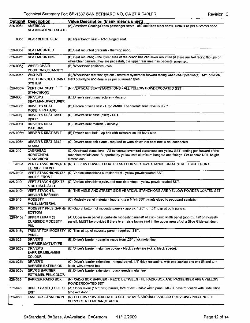
526-005b AMERICAN (A),American Seating/Otaco passenger seats - 850 stainless steel seats. Details as per customer spec.SEATING/OTACO SEATS
005d REAR BENCH SEAT
526-005e SEAT MOUNTEDCRARRAII
526-005f SEAT MOUNTING
526-005g WHEELCHAIRPOSITIONS,QUANTITY
526-005h W/CHAIRPOSiTiONS,RESTRAiNTSYSTEM
526-005w VERTICAL SEATSTANCHIONS
526-006 DRIVER'SSEAT,MANUFACTURER
526-006b DRIVER'S SEATMODELS,RECARO
526-006j DRIVER'S SEAT BASERISER
526-006k DRIVER'S SEATMATERIAL
526-006m DRIVER'S SEAT BELT
526-006n DRIVER'S SEAT BELTALA.RM
(B),Rear bench seat - 1-3-1 hinged seat.
(B),Seat mounted grabrails - thermoplastic.
(B),Seat mounting - the lower area of the coach has cantilever mounted (if there are fwd facing flip-ups orwheelchair barriers, they are pedestal), the upper rear area has pedestal mounted.
(B),Wheelchair positions - two.
(B),Wheelchair restraint system - restraint system for forward facing wheelchair position(s). Mfr, position,rnat'l coior/type and details as per customer spec.
(N),VERTICAL SEATSTANCHIONS - ALL YELLOW POWDERCOATED SST.
(B),Driver's seat manufacturer - Recaro.
(B),Recaro driver's seat - Ergo AM80. The fore/aft seat travel is 9.25".
(C),Driver's seat base (riser) - SST.
(C),Driver's seat material - all vinyl.
(B),Driver's seat belt - lap belt with retractor on left hand side.
(C),Driver's seat belt alarm - required to warn driver that seat belt is not connected.
526-010 OVERHEAD (C),Overhead stanchions - All horizontal overhead stanchions are yellow SST, ending just forward of theHORIZONTAL rear chesterfield seat. Supported by yellow cast aluminum hangers and fittings. Set at basic NFIL heightSTANCHIONS dimensions.
- "-010d VERT.STANCHIONS,STR (N),YELLOW POWDER COATED SST FOR VERTICAL STANCHION AT STREETSIDE FRONTEETSIDE FRONT
526-010e VERT.STANCHIONS,CU (C),Vertical stanchions.curbslde front - yellow powdercoated SST.RBSIDE FRONT
526-01Of VERT STANCH @EXITS (C),Vertical stanchions,exits and rear riser steps - yellow powdercoated SST.& RR RISER STEP
526-010h VERT.STANCH'S, (N),THE AISLE AND STREET SIDE VERTICAL STANCHIONS ARE YELLOW POWDER COATED SST.DRIVER'S BARRIER
526-015 MODESTY (C),Modesty panel material- leather grain finish SST panels glued to pegboard sandwich.PANEL,MATERIAL
526-015b MODESTY PNLS,GAP @ (C),Gap at bottom of modesty panels - approx. 1.25" to 1.31" gap at both panels.BOnOM
526-015e UPPER LEXAN @ (A),Upper texan panel at curbside modesty panel aft of exit - basic width panel (approx. half of modestyCURBSIDE MODESTY panel). MUST be provided if there is an aisle facing seat in the upper area aft of a Slide Glide exit door.PNL
526-015g TRIM AT TOP MODESTY (C),Trim at top of modesty panel- required, SST.PANEL
526-025
526-025a
526-025b
526-025e
526-029
DRIVER'SBARRIER,MAT'L/TYPE
DRIVER'SBARRIER,MELAMINECOLOUR
DRIVER'SBARRIER,EXTENSION
DRVR'S BARRIEREXTN,MEL.PNL.COLOR
BARRIER,RADIO BOX
(B),Driver's barrier - panel is made from .25" thick melamine.
(B),Driver's barrier melamine colour - black cashmere (a.k.a. black suede).
(C),Driver's barrier extension - hinged panel, 1/4" thick melamine, with one locking and one lift and turnlatch, with driver's box.
(B),Driver's barrier extension - black suede melamine.
(N),RADIO BOX BARRIER - REQ'D BETWEEN THE RADIO BOX AND PASSENGER AREA YELLOWPOWDERCOATED SST
- -"-040
[526-050
L.....
UPPER PANEL, FORE OF (A),Upper lexan (1/2" thick) barrier, fore of exit - basic width panel. MUST have for coach with Slide GlideEXIT type exit door.
FAREBOX STANCHION (N),YELLOW POWDERCOATED SST. WRAPS AROUND FAREBOX PROVIDING PASSENGERSUPPORT AT ENTRANCE AREA
S=Standard, B=Base, A=Available, C=Custom 11/12/2009 Page 12 of 14

Technical Summary For: SR-1337 SAN BERNARDINO, CA 27 X C40LFR
Option# Description Value Description (blank means unset)526-055 EMERGENCY (B),Emergency instructions - applied with adhesive.
INSTRUCTIONS
Revision: C
!'?6-055a EMERGENCYINSTRUCTIONS,LANGUAGE
526-060 LUGGAGE RACKS @FRT WHEELHOUSES
(C),Language for emergency instructions - English/Spanish.
(N)FRONT LUGGAGE RACKS - NO STREETSIDE RACK (DUE TO RADIO BOX ARRANGEMENT).CURBSIDE: HORIZ. YELLOW POWDERCOATED SST TUBE WRAPS AROUND AFT, AISLE AND FORESIDES OF y·vHEELHOUSE.
526-060d
526-105
549-005a
549-005b
AFTVERT.STANCH.C/SIDE LUGG.RACK
HANDHOLDSTRAPS,O/HEADSTANCHIONS
HVAC SYSTEM,MFR &TYPEHVAC ELECTRONICS
(A),Vertical stanchion aft of front curbside luggage rack - yellow powdercoated SST
(C),Handhold straps on overhead stanchions - 6 flexible black nylon straps, loose on horizontal stanchions,locations as per customer spec.
(C),HVAC system manufacturer and type - Carrier RM55 rear AlC (non-60' coaches).
(C),HVAC electronics - Carrier Micro-Max system.
549-005e REFRIGERANT
549-005f HVAC FRESH AIRINTAKE
549-005n HVAC UNIT MOTORTYPE
549-005p DEFROSTER
549-00Sq DRIVER'S BOOSTERFAN
549-005qa DRIVER'S BOOSTERFAN CONNECTION
549-005s AlC DRAIN PAN
(A),Refrigerant - R-134a Freon
(B),HVAC fresh air intake - recirculated air only.
(C),HVAC motor type - brushless motor for primary heating &cooling system.
(C),Defroster - with Rotron brushless motor.
(A),Driver's booster fan - MCC driver's overhead fan with brushless motor.
(B),Driver's booster fan connection - to the HVAC (heat or AlC) system.
(B),Ale drain pan - provided for rear mounted Ale, heater or condenser units..
~-005v HVAC SYSTEM VALVES (B),HVAC system valves - gate valves.
549-005x AlC COMPRESSOR (C),AlC compressor - Carrier,05G-41, 41 cubic inch displacement.
549-005zb HVAC RETURN AIR (C),Return air filter - basic filter (hog hair) required at the return air grille (basic provision for roof HVAC,FILTER available for rear HVAC).
549-005zc HVAC,PULLDOWN SPEC (C),HVAC pulldown spec - As per customer spec. This includes extra vents at front area of coach,ductliners for the driver's booster fan and in entrance mech.box, etc.
549-075 CLAMPS,AlC,HEATERLINES
(B),AlC and heater line clamps - Breeze.
549-NEW DRIVER DEDICATED AlC (N),DRIVER'S AlC SYSTEM BUILT INTO DASHSYSTEM
580-005 WHEELCHAIR RAMP (B),Wheelchair ramp - at front door only.
580-005d FRONT RAMP CONTROL (B),Front ramp control - ramp switch @ driver's instrument panel.
600-010 BACK-UP ALARM
600-060 FAREBOX PEDESTAL
600-060a FAREBOX PEDESTALHOLES
600-061 FAREBOX
(B),Backup alarm - basic alarm located on street side.
(B),Farebox pedestal - carbon steel.
(C),Farebox mounting provisions - holes to accept GFI connectors. Must have if NFIL installs GFI farebox.Optional if customer installs.
(C),Farebox - GFI Odyssey, 41" tall.
600-061 a FAREBOX SUPPLIED BY (C),Farebox source of supply - supplied and installed by NFIL.
600-061d FAREBOX POSITION
. '·065 RADIO EQUIPMOUNTINGPROVISIONS
(C),Farebox position - whether installed by NFIL or by customer, is located in customer specified position.
(C),Streetside radio/equipment box - box with aisle facing door, material, internal details and latching as percustomer spec.
600-067 RADIU,l,,;UMMUNIl,,;AlIU (N),t-'Kt:-WIREO 1U Al,,;l,,;uMMUDAl t: ::>it:Mt:NS KAoiu l,,;uMMUNil,,;A1IuN::> ::>Y::> I t:M. INl,,;LUUt:::>I N SYSTEM GPS ANTENNA, RADJOANTENNA AND WLAN ANTENNA
S=Standard, B=Base, A=Available, C=Custom 11/12/2009 Page 13 of 14

Technical Summary For: SR-1337 SAN BERNARDINO, CA 27 X C40LFR Revision: C
Option# Description600-160 METHANE DETECTION
finO-160a METHANE DETECTORILOCATION
buu-170 GROUND STRAP
600-200 FIRE SUPPRESSION
600-200d AMEREXFIREDETECTiON SENSORS
600-265 BICYCLEc/\,...tL l.I:Ollllnnt:1I ~_"IU'II I v.'f.___ ....
Value Description (blank means unset)(C),Methane detection - Amerex Safety Net System, details as per customer spec.
(C),Methane detector locations - 4 detectors, 1 @ roof tanks, 2 @ engine compartment, 1 above ceilingpanel @ inside rear of coach.
(C),Ground straps - two ground straps (straps that hang off structure frame), one front and the second inrear of coach
(C),Fire suppression - Amerex Safety Net System, equipment as per customer spec.
(B),Amerex fire detection sensors - two at streetside and one at curbside of engine compartment.
[(C),Bicycle rack, manufacturer/model - Sportworks, DL2-NP (narrow profile), front mounted.
600-265a SPORlWORKS BICYCLE (C),Sportworks bicycle rack mounting - bolted slide-in standoff with bolted pivot.RACK MOUNTING
600-265b SPORlWORKS BICYCLE (C),Sportworks bicycle rack removal- bolted rack.RACK REMOVAL
600-265d SPORlWORKS BICYCLE (C),Sportworks bicycle rack material/colour - white powdercoated (note: the support arm housing is beadRK MATUCOLOR blasted non-glare SST.).
600-265g BICYCLE RACK (B),Bicycle rack instructions - English.INSTRUCTIONS
600-265h BICYCLE RACK MIRROR {C),Bicycle rack mirror - 6" diameter convex installed at curbside interior.
600-285 VIDEO SURVEILLANCE (A),Video surveillance - provisions, conduit and fish wire.SYSTEt.1
600-285b PROVISIONS INTERIOR VIDEOpI 'O>l£'" o ..cr;;
{N),FISHWIRE AND CONDUIT WITH 1.25" HOLES PLUGGED FOR A 7 CAMERA SYSTEM LAYOUT.INCLUDES ONE EXTERIOR CURBSIDE CAMERA
S=Standard, B=Base, A=Available, C=Custom 11/12/2009 Page 14 of 14

CERTIFICATlONELK GROVE CITY COUNCIL RESOLUTION NO. 2009-228
STATE OF CALIFORNIA )COUNTYOFSACRAMENTO) ssCITY OF ELK GROVE )
I, Susan J. Blackston, City Clerk of the City of Elk Grove, California, do herebycertify that the foregoing resolution was duly introduced, approved, and adoptedby the City Council of the City of Elk Grove at a special meeting of said Councilheld on November 18, 2009 by the following vote:
AYES:
NOES:
COUNCILMEMBERS:
COUNCILMEMBERS:
Hume, Scherman, Cooper, Davis, Detrick
None
ABSTAIN: COUNCILMEMBERS: None
ABSEN~ COUNC~MEMBERS: None