Embed Size (px)
Citation preview

Burgess, ANAGPIC 2014, 1
Aaron Burgess
The State University of New York College at Buffalo
Shattered Earth:
The Treatment of a Twentieth Century Clock and Globe
ART CONSERVATION DEPARTMENT

Burgess, ANAGPIC 2014, 2
Table of Contents
1. Abstract ......................................................................................................................................4
2. Introduction ................................................................................................................................5
2.1 Object Overview ..................................................................................................................5
2.2 Date of Manufacture ............................................................................................................7
2.3 Historical Context ................................................................................................................9
3. Project Presentation ..................................................................................................................15
3.1 Uniclok Condition Assessment ..........................................................................................15
4. Objectives ................................................................................................................................17
5. Technical Breakdown of the Clock and Globe Mechanism ....................................................18
5.1 The Clock ...........................................................................................................................18
5.2 The Globe...........................................................................................................................20
6. Materials and Analysis .............................................................................................................23
6.1 Methods of Analysis and Instrumentation .........................................................................23
6.2 Analysis of the Uniclok’s Polymeric Materials .................................................................25
6.3 Analysis of the Globe Plasticizers .....................................................................................30
6.4 Analysis of the Uniclok’s Inorganic Materials ..................................................................32
7. Treatment .................................................................................................................................38
7.1 Disassembly and Cleaning of the Clock Mechanism ........................................................38
7.2 Rewiring the Clock and Lamp ...........................................................................................39
7.3 Cleaning the Globe Hemispheres.......................................................................................40
7.4 Removal of the Globe Hemispheres from the Frame ........................................................40
7.5 Reassembly of the Globe ...................................................................................................41
7.6 Compensating for Losses to the Globe Gores ....................................................................43
7.7 Disassembly and Cleaning of the Globe Mechanism and Lighting Rig ............................43
7.8 Reconditioning the Friction-clutches .................................................................................46
Burgess, ANAGPIC 2014, 3
7.9 Compensating for the Calottes ...........................................................................................46
7.10 Compensating for the Internal Shade ...............................................................................50
7.11 Replacing the Light Source ..............................................................................................52
8. Conclusions ..............................................................................................................................54
9. Future Research .......................................................................................................................55
10. Acknowledgements ..................................................................................................................56
11. References ................................................................................................................................57
11.1 Published References Cited .............................................................................................57
11.2 Online References Cited ..................................................................................................58
11.3 Published References Consulted ......................................................................................59
12. Materials and Sources ..............................................................................................................60
13. Autobiographical Statement.....................................................................................................62
14. List of Illustrations ...................................................................................................................63
15. Appendices ...............................................................................................................................76
15.1 Appendix 1: Fourier Transform Infrared Spectroscopy Settings .................................76
15.2 Appendix 2: Gas Chromatography - Mass Spectrometry Settings ..............................76
15.3 Appendix 3: X-ray Fluorescence Spectroscopy Settings ...........................................77
15.4 Appendix 4: Spectral Power Distribution Curves for Replacement Light Sources ....77
15.5 Appendix 5: Digital Recreations of the Time and Date Calottes ...............................78
15.6 Preventive Conservation Recommendations ...............................................................79

Burgess, ANAGPIC 2014, 4
1. Abstract
A clock and globe object produced c.1931 by the Universal Clock and Globe Corporation,
was researched, analyzed and treated at the Buffalo State Art Conservation Department. The
composite piece was both aesthetically and functionally compromised, having advanced
polymeric decomposition and extensive metal corrosion. Research provided an historical context
for the object, while also elucidating its technology and intended functionality. The material
composition of the object was determined using a combination of microchemical testing, Fourier
Transform infrared spectroscopy (FTIR), gas chromatography-mass spectrometry (GC-MS) and
X-ray Fluorescence spectroscopy (XRF). The instrument’s functionality was restored by
reconstructing the highly degraded plastic components in polymethyl methacrylate (PMMA),
and de-corroding the bound internal gear trains. Degraded electrical wiring was replaced to
ensure that the device could be used safely. The most appropriate internal illumination source
was determined by measuring the spectral power distribution for various LED and incandescent
bulbs. Heavy tarnishing was reduced from the clock case and base, restoring its original
surfaces. The fragile nitrocellulose globe was damaged during treatment, but was consolidated
and strengthened with Paraloid B-67 resin and Cerex. Japanese tissue fills were used to
compensate for losses to the globe gores.

Burgess, ANAGPIC 2014, 5
2. Introduction
2.1 Object Overview
The Art Deco style globe/clock object was designed and produced by the ‘Universal
Clock and Globe Corporation’ (Wilmington, Delaware) with a clock movement provided by
the Warren Telechron Company, based in Ashland, Massachusetts. While the maker of the
twelve inch plastic globe is unknown, the paper gores were supplied by Rand McNally. The
metal frame and casing were die-cast by the Sterling Die-casting Co., of Brooklyn, New
York. The gears for the globe’s internal mechanism were produced by Boston Gear
Company, and the lamp socket fixture was made by the Arrow- Hart & Hegeman Electric
Company.
Both the clock and globe are mounted in a common support
structure made from a zinc-based casting alloy. The Telechron
clock is operated by a synchronous AC motor, which in turn powers
the internal globe trains. Two wings fan out from the clock to
support a circular ring, in which the globe is mounted, set on an
angle of approximately 23 ½ degrees to the vertical. The circular
ring is hinged such that the two inter-fitting globe hemispheres can
be separated to access the inner workings of the globe which
include a small incandescent bulb. The globe is geared to rotate one
full revolution every twenty-four hours while accurately reflecting
day and night at any given point in time around the world by way of
its internal light source. In its original form the light bulb would
have been shielded on one side so that only half of the globe was
illuminated at any one time. This shielded light-source is set
vertically, offset from the axis of the globe by 23 ½ degrees and is
geared to revolve 1/365 of a revolution every day in order to show
seasonal variation in the Earth’s shadow.
The Uniclok instrument was marketed to consumers in the early
thirties. A National Geographic advertisement for Uniclok from
November 1930 describes a very similar timepiece (which has a
different base, but otherwise is identical in appearance) in the
Figure 1: November 1930 National Geographic advertisement clipping for the Uniclok globe.

Burgess, ANAGPIC 2014, 6
following terms (see Figure 1):
“An electrical clock and chronological instrument which shows instantly the
correct time all over the world, the period of day and night, the seasons, and
position of the earth and sun in their proper relations to their respective orbits.
The translucent globe is illuminated from within, realistically representing day
and night throughout the world. The globe rotates on its axis once a day; the
shadow revolves once a year, showing daylight, darkness, and the rotation of the
seasons as they exist on the earth... Complete manual and textbook supplied
with each Uniclok. They are sold by Telechron dealers and power company
stores everywhere in the United States.”
Another advertisement for the Uniclok appeared a year later in
the November issue of The Literary Digest (Funk and Wagnalls
1931) (see Figure 2). The model shown is identical to the object
owned by the Buffalo Museum of Science (see Figure 3), indicating
that the design of the base had changed within the year from hard-
edged geometric forms to a more rounded and classically inspired
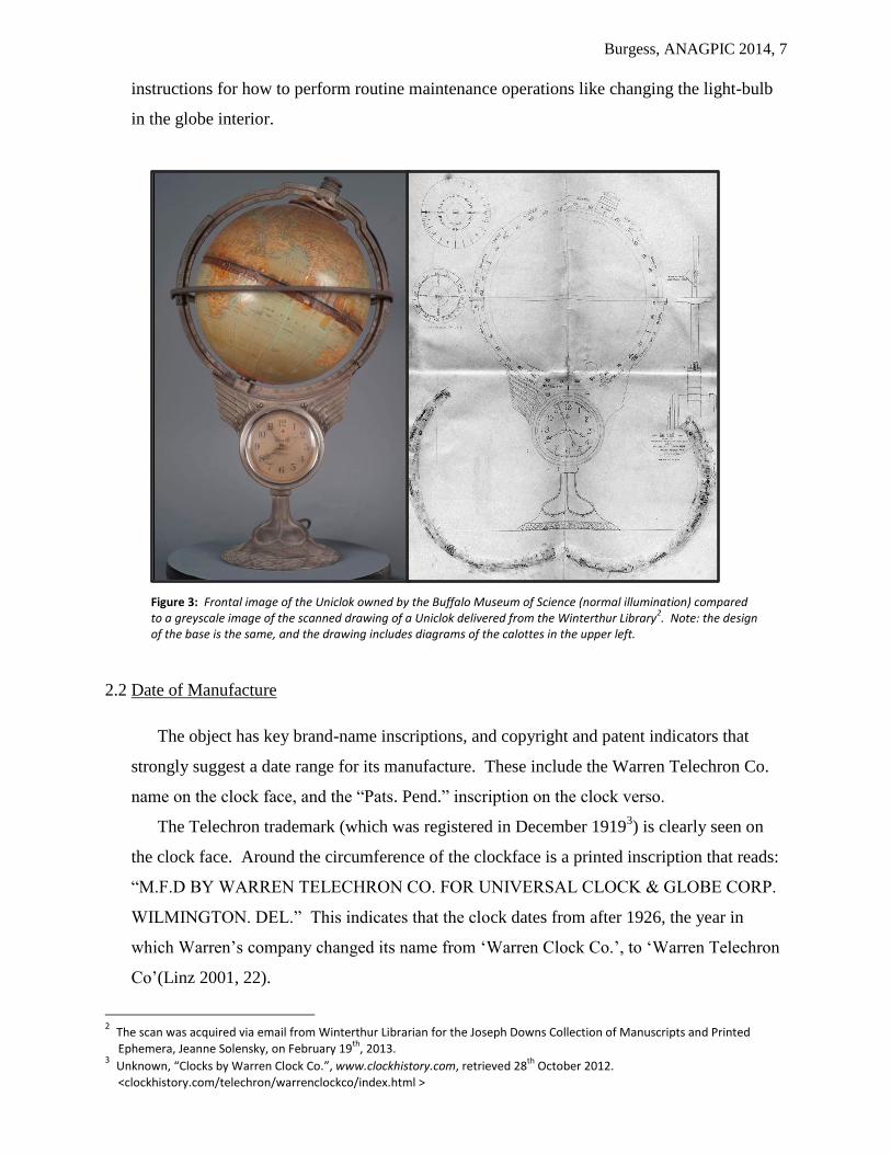
molding. This evolution of design is also reflected in a technical
drawing of the Uniclok globe included in paraphernalia related to
silver-smithing once owned by American silver scholar, D. Albert
Soeffing1. His collection now resides in the Winterthur Library,
Winterthur, DE. The drawing also shows the more classical base
consistent with the Buffalo Uniclok.
As stated in the National Geographic advertisement, the object
was originally sold with a handbook titled: The Earth : Uniclok
Globe Handbook : A Pocket Manual of the Earth, Moon, Sun,
Planets, Stars and… authored by Herman E. Schulse. The booklet was both educational and
promotional. While it enlightened the owner with relevant information about the earth,
moon, sun and solar system, it also detailed the various features of the globe-clock, how to
clean it, while also describing the various models and finishes in which the piece could be
presented. Finishes included; ‘Museum Bronze’, ‘Antique Bronze’ and ‘Antique Silver’
(Schulse 1931). The handbook was an invaluable resource for this study as it also included
1 The Winterthur Library, “The Joseph Downs Collection of Manuscripts and Printed Ephemera”, retrieved November 30
th 2012:
<findingaid.winterthur.org/html/HTML_Finding_Aids/COL0774.htm>
Figure 2: An advertisement for the Uniclok globe shown in The Literary Digest from November 14, 1931. The globe is identical to the object that is the focus of this study.
Burgess, ANAGPIC 2014, 7
instructions for how to perform routine maintenance operations like changing the light-bulb
in the globe interior.
Figure 3: Frontal image of the Uniclok owned by the Buffalo Museum of Science (normal illumination) compared to a greyscale image of the scanned drawing of a Uniclok delivered from the Winterthur Library
2. Note: the design
of the base is the same, and the drawing includes diagrams of the calottes in the upper left.
2.2 Date of Manufacture
The object has key brand-name inscriptions, and copyright and patent indicators that
strongly suggest a date range for its manufacture. These include the Warren Telechron Co.
name on the clock face, and the “Pats. Pend.” inscription on the clock verso.
The Telechron trademark (which was registered in December 19193) is clearly seen on
the clock face. Around the circumference of the clockface is a printed inscription that reads:
“M.F.D BY WARREN TELECHRON CO. FOR UNIVERSAL CLOCK & GLOBE CORP.
WILMINGTON. DEL.” This indicates that the clock dates from after 1926, the year in
which Warren’s company changed its name from ‘Warren Clock Co.’, to ‘Warren Telechron
Co’(Linz 2001, 22).
2 The scan was acquired via email from Winterthur Librarian for the Joseph Downs Collection of Manuscripts and Printed
Ephemera, Jeanne Solensky, on February 19th
, 2013. 3 Unknown, “Clocks by Warren Clock Co.”, www.clockhistory.com, retrieved 28
th October 2012.
<clockhistory.com/telechron/warrenclockco/index.html >
Burgess, ANAGPIC 2014, 8
The Universal Clock and Globe Corp, earned a copyright for the Uniclok device on July
14th 1931 (Library of Congress Copyright Office 1932, 998). This is however not the most
reliable method for dating the object given that it could have easily gone in to mass
production without a copyright being awarded.
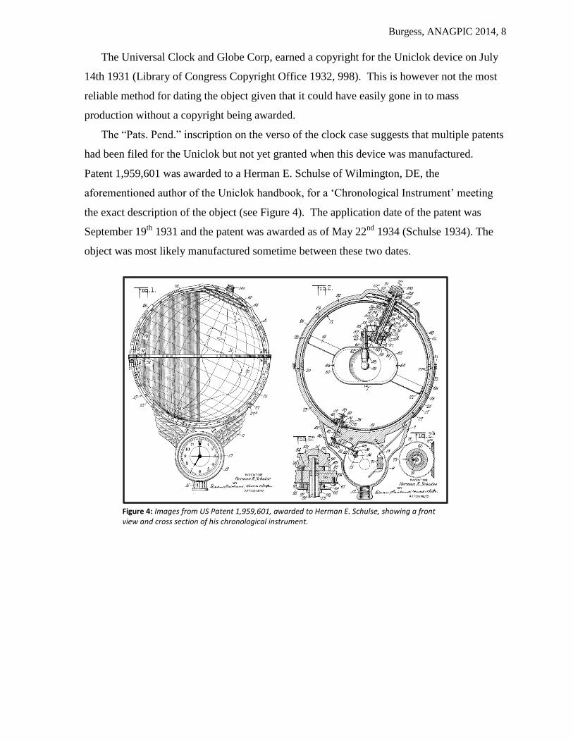
The “Pats. Pend.” inscription on the verso of the clock case suggests that multiple patents
had been filed for the Uniclok but not yet granted when this device was manufactured.
Patent 1,959,601 was awarded to a Herman E. Schulse of Wilmington, DE, the
aforementioned author of the Uniclok handbook, for a ‘Chronological Instrument’ meeting
the exact description of the object (see Figure 4). The application date of the patent was
September 19th
1931 and the patent was awarded as of May 22nd
1934 (Schulse 1934). The
object was most likely manufactured sometime between these two dates.
Figure 4: Images from US Patent 1,959,601, awarded to Herman E. Schulse, showing a front view and cross section of his chronological instrument.
Burgess, ANAGPIC 2014, 9
2.3 Historical Context
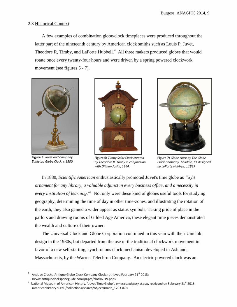
A few examples of combination globe/clock timepieces were produced throughout the
latter part of the nineteenth century by American clock smiths such as Louis P. Juvet,
Theodore R, Timby, and LaPorte Hubbell.4 All three makers produced globes that would
rotate once every twenty-four hours and were driven by a spring powered clockwork
movement (see figures 5 - 7).
Figure 5: Juvet and Company Tabletop Globe Clock, c.1880.
Figure 6: Timby Solar Clock created by Theodore R. Timby in conjunction with Gilman Joslin, 1864.
Figure 7: Globe clock by The Globe Clock Company, Milldale, CT designed by LaPorte Hubbell, c.1883
In 1880, Scientific American enthusiastically promoted Juvet's time globe as “a fit
ornament for any library, a valuable adjunct in every business office, and a necessity in
every institution of learning."5 Not only were these kind of globes useful tools for studying
geography, determining the time of day in other time-zones, and illustrating the rotation of
the earth, they also gained a wider appeal as status symbols. Taking pride of place in the
parlors and drawing rooms of Gilded Age America, these elegant time pieces demonstrated
the wealth and culture of their owner.
The Universal Clock and Globe Corporation continued in this vein with their Uniclok
design in the 1930s, but departed from the use of the traditional clockwork movement in
favor of a new self-starting, synchronous clock mechanism developed in Ashland,
Massachusetts, by the Warren Telechron Company. An electric powered clock was an
4 Antique Clocks: Antique Globe Clock Company Clock, retrieved February 21
st 2013:
<www.antiqueclockspriceguide.com/pages/clock6919.php> 5 National Museum of American History, “Juvet Time Globe”, americanhistory.si.edu, retrieved on February 21
st 2013:
<americanhistory.si.edu/collections/search/object/nmah_1203340>

Burgess, ANAGPIC 2014, 10
interesting choice for the Uniclok object given that electric movements were eyed with
suspicion in their early days of manufacture. The Universal Clock and Globe Corporation
did however embrace a sense of the ‘new’ by using the Telechron technology, while also
leveraging the ability to operate the clock and the translucent globe’s internal light source
using the same power source.
Electric clock movements were first considered as early as 1770, and were refined
through several iterations until the twentieth century invention of a reliable synchronous AC
motor which is used in the Uniclok object.6 One of the earliest allusions to an electric clock
was in astronomer James Ferguson’s book Introduction to Electricity, where he included a
plate showing an electrically driven clock and orrery (Aked, 1986). The first electrostatic
pendulum clock was created in 1814 by Sir Francis Ronalds using a dry-pile battery. The first
patented electric clock movement was introduced in 1841 by Alexander Bain (Aked, 1986),
and used an electromagnetic field to drive its pendulum. Further experimentation and
investigation into alternating current throughout the late nineteenth century by people such as
Michael Faraday and Nikola Tesla led to the development of synchronous and asynchronous
AC motors. The clock movement in the Uniclok was born out of these developments.
The Telechron self-starting synchronous electric motor was patented in 1918 by Henry E.
Warren (1872-1957) (Linz 2001, 17), a prolific and celebrated inventor who died with over
one hundred and thirty patents to his name. The motor relied on a consistent supply of
alternating current operating at a frequency of sixty hertz in order to keep time. Electric
utilities were notoriously inconsistent in managing their output frequency at this time, which
had disastrous impact for the production and acceptance of early synchronous motor clocks.
If the local power company was producing electricity at anything but an accepted and
predictable number of cycles per second then the clocks would not keep accurate time. One
of the most intriguing aspects to the Telechron story is the way in which Henry Warren
tackled this problem. To ensure his clocks’ commercial viability he created a governor, the
Warren Master Clock, that he campaigned to have installed at his local power company,
Boston-Edison, to act as a frequency regulator (Linz 2001, 13). The master clock had dual
movements; one driven by a sixty hertz synchronous motor connected to the current
produced by the power plant, the other driven by a traditional spring and pendulum
mechanism. If the hands of the electric clock moved along perfectly with those of the
‘traditional’ clock, the power produced by the electric company was deemed to be of uniform
6 After this time the refinement continued with the advent of the quartz clock, and its combination with solid state electronics
which allowed quartz timekeepers to be significantly reduced in size.
Burgess, ANAGPIC 2014, 11
frequency. If the movements were out of synch then the station operator could adjust the
turbine governors on the generator to bring the hands back into accordance (Holcomb III,
Webb 1985). To ensure the overall accuracy of the system the pendulum clock was
synchronized twice a day with time signals received from the master clock at the US Naval
Observatory. With Warren’s master clock in place the utility was able to fulfill its promise
of providing a predictable sixty-cycle alternating current power supply, and the Telechron
clocks were able to achieve astonishing accuracy.
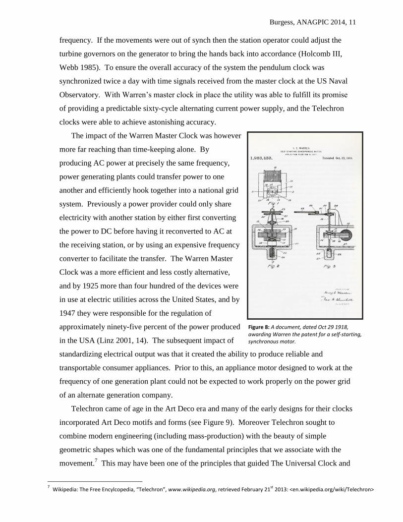
The impact of the Warren Master Clock was however
more far reaching than time-keeping alone. By
producing AC power at precisely the same frequency,
power generating plants could transfer power to one
another and efficiently hook together into a national grid
system. Previously a power provider could only share
electricity with another station by either first converting
the power to DC before having it reconverted to AC at
the receiving station, or by using an expensive frequency
converter to facilitate the transfer. The Warren Master
Clock was a more efficient and less costly alternative,
and by 1925 more than four hundred of the devices were
in use at electric utilities across the United States, and by
1947 they were responsible for the regulation of
approximately ninety-five percent of the power produced
in the USA (Linz 2001, 14). The subsequent impact of
standardizing electrical output was that it created the ability to produce reliable and
transportable consumer appliances. Prior to this, an appliance motor designed to work at the
frequency of one generation plant could not be expected to work properly on the power grid
of an alternate generation company.
Telechron came of age in the Art Deco era and many of the early designs for their clocks
incorporated Art Deco motifs and forms (see Figure 9). Moreover Telechron sought to
combine modern engineering (including mass-production) with the beauty of simple
geometric shapes which was one of the fundamental principles that we associate with the
movement.7 This may have been one of the principles that guided The Universal Clock and
7 Wikipedia: The Free Encylcopedia, “Telechron”, www.wikipedia.org, retrieved February 21
st 2013: <en.wikipedia.org/wiki/Telechron>
Figure 8: A document, dated Oct 29 1918, awarding Warren the patent for a self-starting, synchronous motor.

Burgess, ANAGPIC 2014, 12
Globe Corporation’s choice to select Telechron as
their timepiece manufacturer. The metal wings
supporting the globe on the Uniclok object have a
distinctive Art Deco appeal, so what better choice of
partner than Warren’s Telechron company to produce
an Art Deco object given that they were at the cutting
edge of horologic technology at that time?
Not a lot of information exists regarding the
Universal Clock and Globe Corporation, other than
their location in Wilmington, DE, and the identity of
the Uniclok globe’s designer, Herman E. Schulse, as
indicated by the Uniclok’s patent. It is known that the
company produced at least one other electric clock in 1930 in conjunction with Haydon
Manufacturing Co. Arthur William Haydon (1906-1982) was another inventor of
synchronous electric clock movements and, although thirty-four years Warren’s junior, was
already actively producing clock movements in the late 1920s.
Two maker’s marks inside the Uniclok casing (see inset image in Figure 10) show that its
production was outsourced to Sterling Die-Casting Co., of Brooklyn, New York. The fact
that the Universal Clock and Globe Corporation employed clock movements from multiple
vendors, and did not manufacture the clock cases themselves, suggests that they may have
been primarily in the business of designing and assembling their products.
Figure 10: A series of images related to the Sterling Die Casting Co of Brooklyn, NY. Inset is an image of the maker's mark found on the object. The leftmost image is the exterior of the building at 743 39th Street, Brooklyn, NY. The central image shows the factory floor, while the rightmost image shows the finishing and packing room. A calendar on the back wall of this final image shows the month and year to be December, 1930. (Source: eBay.com, March 25
th 2013).
Figure 9: The Art Deco inspired Telechron Model 700 “Electrolarm”, 1929-1931.

Burgess, ANAGPIC 2014, 13
Herman E. Schulse’s exact function within the Universal Clock and Globe Corporation is
not clear, but he did apply for a number of patents related to mechanical features and designs
for the Uniclok product from 1929 through 1931 (see table 1), and the fact that his name
appears on the patent suggests that he was a key figure in the company’s endeavors. The
majority of the patents from this time period are related specifically to clock case designs
(see Figure 11), which reinforces the theory that Universal Clock and Globe Corporation was
focused more on producing the exterior of the clock than the timing mechanism itself.
Figure 11: Images from Schulse's design patents specifically related to clock cases and globe fixtures produced by the Universal Clock and Globe Corp. From left to right, with the US design patent numbers in parentheses: terrestrial globe frame (Des84,795), Rajah terrestrial globe support (Des84,796), 122-L terrestrial globe support (Des85,206), De Soto terrestrial globe and clock support (Des85,207) and a wall hanging globe fixture (Des86,937).
Schulse’s entire patent portfolio spans the period 1917 through 1956. A selection of Schulse’s
patents is listed in Table 1, and illustrates him as an inventor who was quite varied in his interests.
At least nine of these patents relate directly to products sold by the Universal Clock and Globe
Corporation, and two entries (patent 1,959,601 and design patent 84,794) are specifically related
to the instrument owned by the Buffalo Museum of Science (Schulse 1931, 1934).

Burgess, ANAGPIC 2014, 14
Table 1: A selection of patents awarded to Herman E. Schulse including the filing date, dated awarded and patent number. The shaded entries are patents related to directly to the Universal Clock and Globe Corporation, and those in bold relate specifically to the Uniclok instrument owned by the Buffalo Museum of Science.
Invention Patent Filed Patent
Granted US Patent #
Water Cooler Dec. 2nd
1915 Jun. 5th
1917 1,228,836
Liquid Dispensing and Filtering Bottle Jun. 20th
1916 Jun. 5th
1917 1,228,837
Apparatus for Manufacture of Filtering
Films Feb. 8
th 1918 Oct. 12
th 1920 1,355,292
Fibrous Filtering Film May 28th
1918 Aug. 30th
1921 1,389,401
Process for Making Fibrous Filtering Films Feb. 8th
1918 Oct. 11th
1921 1,392,989
Shoe Shine Installation Oct. 29th
1927 Oct. 23rd
1928 1,688,753
Shoe Shine Seat Jun. 5th
1928 Oct. 23rd
1928 Des 76,729
Dispensing Container Oct. 17th
1927 Nov. 4th
1930 1,780,508
Shoe Shine Installation Jan. 17th
1927 Oct. 27th
1931 1,828,820
Shoe Shine Last Jun. 5th
1928 May 24th
1932 1,859,536
Flexible Shaft Jul. 23rd
1928 Jun. 6th
1933 1,912,658
Terrestrial Globe Frame and Clock
Casing Apr. 11
th 1931 Aug. 4
th 1931 Des 84,794
Terrestrial Globe Frame Apr. 11th
1931 Aug. 4th
1931 Des 84,795
Terrestrial Globe Frame and Support
(Elephant “Rajah” Desk Model) Apr. 11
th 1931 Aug. 4
th 1931 Des 84,796
Terrestrial Globe Frame and Support Apr. 11th
1931 Aug. 18th
1931 Des 84,903
Terrestrial Globe Frame and Support
(“122-L” Floor Model) Apr. 11
th 1931 Sep. 22
nd 1931 Des 85,206
Terrestrial Globe Frame and Clock Casing
Support (“De Soto” Floor Model) Apr. 11
th 1931 Sep. 22
nd 1931 Des 85,207
Globe Fixture Sep. 29th
1931 May 10th
1932 Des 86,937
Chronological Instrument Sep. 19th
1931 May 22nd
1934 1,959,601
Chronological Instrument Jul. 16th
1929 May 7th
1935 2,000,457
Beverage Conditioner and Dispenser Dec. 28th
1934 Aug. 11th
1936 2,051,013
Bar Rinsing Equipment Sep. 29th
1936 Dec. 22nd
1936 2,065,347
Beverage Dispensing Container Sep. 9th
1933 Nov. 2nd
1937 2,098,210
Brew Cooling Device Jul. 18th
1936 Nov. 2nd
1937 2,098,211
Brew Cooling Installation Sep. 9th
1933 Nov. 28th
1939 2,181,710
Keg Cooling Installation Jul. 18th
1936 Mar. 12th
1940 2,193,540
Brew Draft Equipment Dec. 28th
1934 Apr. 9th
1940 2,196,709
Beverage Container Nov. 8th
1937 Jul. 15th
1941 2,249,051
Chemical Feeder Oct. 2nd
1952 Oct. 23rd
1956 2,767,846

Burgess, ANAGPIC 2014, 15
3. Project Presentation
The Buffalo Museum of Science has entrusted the Buffalo State Art Conservation
Department with the restoration and preservation of an electric clock and globe created by the
‘Universal Clock & Globe Corporation’. The object features a number of potentially
complicated treatments that span a variety of materials. Characterizing the various materials also
presents the opportunity to use analytical techniques and equipment currently available within
the department.
3.1 Uniclok Condition Assessment
In its current state, the object is structurally, aesthetically and functionally compromised.
The globe form supporting the paper gores is split, and as such the two hemispheres do not fit
together correctly. The paper gores have an aged coating that has discolored considerably,
and appears blotchy in places. Previous restoration attempts are evident in the selective
rewiring of the internal components with newer plastic sheathed wires, and presence of
heavily degraded pressure sensitive tapes applied to the paper gores around the equator. The
tape is very discolored and brittle, and appears to have negatively impacted the surrounding
paper support. Two calottes surrounding the North Pole are in an advanced state of polymer
deterioration. The discs have discolored and become very deformed. The lower calotte has
broken away from a geared mechanism at the top of the globe that controlled its rotation,
thus the function of the disc is also impaired in its current state. In addition, pieces of the
calottes have broken away and become fused to the paper gores. The electrical wiring is
exposed in places and as such the piece cannot be safely connected to a power source to
assess its functionality without some intervention.
The nitrocellulose globe material is extremely brittle. Both the upper and lower
hemispheres are cracked. The crack in the upper hemisphere is 5 ½” in length and travels
upwards from the equator through the central Pacific Ocean to the Aleutian Islands. The
crack in the lower hemisphere is 5 ¾” in length and travels towards the pole in an arced
fashion starting in western equatorial Africa. In both instances the brittle gores have tears
corresponding to the crack.
The flange on the lower hemisphere displays extensive internal crazing corresponding to
the adhesive line. This crazing also appears to continue through to the globe which may
Burgess, ANAGPIC 2014, 16
indicate that the adhesive used to join these two pieces has locally accelerated the aging of
the plastic.
The cellulose acetate light shade, that was formerly responsible for indicating which
portions of the globe were in darkness and which were in light, is severely degraded. The
dark-brown, glassy and incredibly brittle form has shattered, fallen out of its mount next to
the light bulb, and is now lying in the bottom of the globe accompanied by a greasy residue.
Every part of the internal mechanism of the globe has a layer of white corrosion, likely
caused in part by exposure to the off-gassing of acetic acid from the degraded cellulose
acetate shade.
The paper gores are extremely brittle, especially around the equator of the lower
hemisphere where the paper has a brown stain ~ ¾” wide. This staining corresponds to the
adhesive join of the cellulose nitrate flange to the lower hemisphere substrate. The stain may
have developed from the migration of the adhesive through the plastic, or it may have been
caused by acidic off-gassing resulting from the localized degradation of the nitrocellulose
substrate around the equator (noted above). There are numerous instance of localized tenting
of the paper support on the globe surface. Pressure sensitive tape has been applied directly to
the paper across the equator seam, presumably to hold the globe together. The tape has
become brittle and discolored. There are localized losses to the paper gores especially
around the equator, and the North Pole. The northern regions of the globe where the paper
has come into contact with the deteriorated celluloid calottes is characterized by a ring of
reticulated brown accretions.
Other than a layer of dust and dirt, the majority of the external metal structure is covered
in a thick, dark-grey oxide, all of which gives the object an overall dull appearance. The
hinge on the PL front face of the latitude indicator ring is broken and one whole side of the
hinged joint is missing. This makes the globe and its supporting structure somewhat unstable
when it is in its opened position. The calendar ring is slightly warped and there is an
irregular shaped deposit of material on the top rear (PR) of the calendar ring.
The two cellulose acetate calottes at the North Pole are heavily degraded and deformed.
The upper calotte (date dial) is delaminating and has numerous losses. The lower calotte
(time dial) has broken away from a geared mechanism at the top of the globe that once
controlled its rotation, thus impeding the functionality of the dial. As the polymer has
degraded the lower calotte has become fused to the upper gores. A faint crack extends across

Burgess, ANAGPIC 2014, 17
the lower calotte, essentially splitting the disc in half. The calottes exhibit both an oily
residue on their surfaces, and what appears to be a needle-like, crystalline solid.
The rubber sheath of the main power cord is split where it enters the metal body of the
globe, and also where it enters the plug. The copper wires are exposed at the screw-
connectors in the plug. If the plug once had a protective cap to shield the user from the
internal wiring, it is now missing.
4. Objectives
As indicated by the condition assessment, the state of the object is somewhat dire. The
curator at the Buffalo Museum of Science recognizes that some of the condition problems may
be unsolvable, but is hopeful that the piece and some semblance of its unique functionality can
be salvaged. The overall objectives for this project are:
To use scientific analysis and scholarly research to identify the original materials and
techniques used in the construction of the piece.
To establish how the clock and globe mechanism works.
To reduce the oxidative layer on the metal clock casing and reveal the original metal
coating, or patina.
To consolidate the cracks in the globe and safely provide a supportive lining for the globe
to minimize damage as the globe material degrades.
To return the clock and globe to a functional state, as much as safely possible, while
maintaining the look and feel of the original mechanism and electrical wiring. This will
also involve the refabricating of the degraded calottes.

Burgess, ANAGPIC 2014, 18
5. Technical Breakdown of the Clock and Globe Mechanism
5.1 The Clock
Parts of the clock and globe train are indicated by capital letters that relate to Figure 12
through Figure 14. The heart and soul of the Uniclok is a Telechron Type-B2 synchronous
motor. It provides enough torque to power all of the clock trains as well as those that control
the rotation of the globe and the internal light
shade/filter. The Type-B motor was patented by Henry
Warren in 1922 (Warren, 1922).
The motor is mounted to the rear of the brass base
plate where it sits in a Telechron B coil or stator. The
coil is an electromagnet whose poles (A,B) are
positioned around the tail of the electric motor which
houses a rotor. The stator also has two shading coils
(C, D) which create a rotary magnetic field and power
the motor’s internal rotor by magnetic induction
(Warren, 1918). With a 60 hertz alternating current
power supply the rotor spins at ~3600 revolutions per
minute (RPM) about a central shaft. A reduction train
in the motor reduces the output to 1 RPM (Clockhistory.com, October 28th
2012).
The long, hollow output shaft (E) and pinion (F) from the electric motor are fitted
through an aperture in the plate. The shaft and pinion rotate at one revolution per minute and
acts as the central arbor for the dial train. The second hand (S) is press-fit into the motor’s
hollow shaft and thus rotates once every sixty seconds as expected. The 9 tooth pinion (F) on
the output shaft (E) powers the entire dial train.
The first gear in the dial train is a 60 tooth wheel (G) co-axled with a 7 tooth pinion (H).
The pinion drives the 63 tooth center wheel (I) and 14 tooth cannon pinion (J) which is
centered on a hollow shaft (K) to which the minute hand (Q) is attached and which slides
over the shaft from the motor. The minute hand is secured to the shaft using a knurled ring
(R) which screws to threading on the center wheel shaft.
The hour train is powered by the cannon pinion (J) driving the 28 tooth minute wheel (L)
which is co-axled with a 6 toothed pinion (M). This pinion in turn drives the 36 tooth hour
Figure 12: Telechron Type B coil or 'stator' showing the poles of the magnet (A,B) and the shading coils (C,D).
A B
D
C

Burgess, ANAGPIC 2014, 19
wheel (N), which is attached to the overall mechanism via the hour pipe (O), a hollow shaft
that slides over the concentric shafts of the motor and center wheel at the center of the plate.
The hour hand (P) is pressure fit to the hour pipe.
Figure 13: Accessory image of clock parts. From left to right, a Telechron Type-B synchronous motor (E,F), the hour wheel (N), the hour hand (P), the center wheel (I), the knurled ring (R), the minute hand (Q) and the second hand (S).
E
F
P Q
R
S
N I
Figure 14: Visual breakdown of the dial train clock components: The leftmost image shows the clock plate with the motor shaft (E) and pinion (F) inserted from the rear. The center image shows the dial train with the center wheel (I) and cannon pinion (J) installed over the motor shaft, driving the minute wheel (L,M). The rightmost image shows the hour wheel (N,O) installed over the shaft of the minute wheel.
F
G H
I
J
K
M
L
O
N

Burgess, ANAGPIC 2014, 20
5.2 The Globe
The Uniclok globe mechanism is a complicated device containing two dial trains in
addition to that of the clock. These trains are responsible for the automatic rotation of the
globe, and the annual rotation of the light shade about the internal light source to indicate the
shadow of the Earth in relation to the seasons.
The first globe train starts from an irreversible worm gear connected to an arbor extended
through the rear of the main plate from the hour train. The worm gear (A) is the beginning of
an overall reduction train that reduces the rate of rotation of the hour train by a factor of
twenty-four such that the globe rotates on its axis one full revolution in a twenty-four hour
period. The worm initiates this process by turning one full revolution every two hours. The
worm meshes with a pinion (B) that drives a twelve to one reduction train comprised of two
drive-shafts (C, D) positioned at ninety degrees to one another. The second shaft (D) in this
assembly is the main axis of the lower hemisphere.
The two halves of the globe are joined together by a flange on the inside rim of the
equator. The tight pressure fit between the two hemispheres ensures that the lower half of
the globe drives the upper portion. The motion of the lower hemisphere is transferred to a
second gear train contained within the globe that automatically rotates the day/night
discriminator 1/365 of a revolution every day. The hub (E) that connects the upper
hemisphere to the upper frame supports a beveled frusto-conical gear (F). The gear train is
centered about a cast zinc bracket that is used to hold many of the mechanical features in
place. The aforementioned beveled gear (F) slides up and down on the hub’s shaft on a key,
A
B C
D
Figure 15: The drive train that controls the rotation of the lower hemisphere with significant features labeled.

Burgess, ANAGPIC 2014, 21
relying on gravity to ensure a constant engagement with an identical beveled gear (G) set in a
perpendicular orientation, thus bending the axis of rotation of the gear train by ninety
degrees. Both beveled gears have the same number of teeth and thus revolve in concert with
the globe at one revolution per day. The second beveled gear is co-axled with an eight
toothed pinion (H). The pinion drives a seventy-three toothed wheel (I), which in turn drives
a shaft supporting another irreversible worm-gear (J) at a rate of one revolution every nine
days and three hours. The worm gear (J) is meshed with a forty tooth worm-wheel (K), that
once again bends the axis of rotation ninety degrees and reduces the revolution rate to once
per year (Schulse 1934)8. The worm-wheel is set on friction clutch that also supports a
secondary wheel (L) that drives an intermediate idler (M) which in turn drives the gear
mounted to the light shade support (N). This latter gear and the gear connected to the worm-
wheel by the friction clutch both have twenty four teeth and thus provide no further
reduction, transferring the rotation rate of one revolution per year to the light shade.
8 Note: the gear ratios on the Uniclok reduction train differ from those outlined in the patent document (US1,959,601)
(Schulse 1934) which reduced the rate of reduction with a six tooth pinion, followed by a seventy-three toothed wheel and a thirty toothed worm-wheel. The net reduction in revolution rate is however identical.
J
E
F
G
N
H
I
K
L
I
M
G
J
Figure 16: The gear train for the internal mechanism driving the daylight/night discriminator, with significant features labeled.

Burgess, ANAGPIC 2014, 22
Two features critical to the success of the clock as a demonstration tool are the friction
clutches located at the southern point of attachment, and in lower internal mechanism. Both
clutches are essentially comprised of two metal discs set together with a compressed spring.
They ensure that the motion of the clock and internal mechanisms can be the transmitted to
subsequent sections of the gear train, while not allowing the manual rotation of the globe or
the daylight/night discriminator to interfere with and damage the clock movement.
Figure 17: The two friction clutches used in the globe gear train. The leftmost image is the clutch at the attachment point of the southern hemisphere, which enables the globe to be rotated in any direction without thwarting the clock movement. The image on the right is the clutch from the gear train for the daylight/night discriminator which allows the lightshade to be manually rotated without impacting the upstream components of the mechanism.
Burgess, ANAGPIC 2014, 23
6. Materials and Analysis
The Uniclok globe was analyzed in order to characterize its materials, which would in turn
influence the most appropriate treatment for each of its constituent components. The clock and
globe instrument is a composite object made up of various metal alloys, polymeric materials,
paper gores and coatings. Each of these required different handling and treatment regimes,
which needed to be compatible with surrounding materials. For example, it would not have been
appropriate to remove a coating from the paper gores using a polar solvent without knowing
what effect this would have on the underlying plastic substrate. A combination of analytical
techniques was performed on the Uniclok to identify organic and inorganic compounds in the
materials including microchemical testing, Fourier Transform Infrared (FTIR) spectroscopy, Gas
Chromatograpy - Mass Spectrometry (GC-MS), and X-ray Fluorescence (XRF) spectroscopy.
6.1 Methods of Analysis and Instrumentation
Microchemical spot testing is a cost effective method to assist in the identification of an
unknown material, and is an excellent complement to more sophisticated analytical
techniques. Many of the published spot tests can be completed with chemicals and
equipment commonly found in a scientific laboratory. Two test methods were selected from
Material Characterization Tests for Objects of Art and Archaeology (Odegaard et al., 2000)
to attempt to identify the material used to make the globe calottes. Given the age of the piece
it was likely that the unknown plastic was cellulose based, so the first test looked for the
presence of cellulose. This test was combined with another that specifically looked for the
presence of cellulose nitrate.
Fourier Transform Infrared Spectroscopy uses infrared radiation to excite organic
molecules in order to produce translational, rotational and vibrational motion. The energy
required to excite the molecule and produce these movements are characteristic of specific
functional groups within the molecule’s atomic structure. The measurement and
interpretation of characteristic energy and motion signatures is realized in a spectrum. The
spectrum can then be used to determine the identity of an unknown material through analysis
of the characteristic peaks present in a sample, and is aided by comparison with published
library spectra of specific known compounds. FTIR analysis is generally thought of as being
destructive or micro-destructive, especially where techniques that require sampling and/or
the use a compression diamond cell are involved. The use of an Attenuated Total
Burgess, ANAGPIC 2014, 24
Reflectance (ATR) accessory can provide non-destructive infrared spectroscopic analysis of
an object depending on its size and fragility, ie: a relatively dense object that is hearty
enough to manipulated and pressed with some force against the diamond ATR crystal while
the analysis is completed.
Pyrolysis Gas Chromatography – Mass Spectrometry (Py-GC-MS) is an analytical
technique ideally suited to the identification of individual components in complex mixtures.
In this study it was specifically employed to identify the plasticizers used in the production of
the globe material. Py-GC-MS is a three-part process. Firstly, the sample is rapidly heated
in the absence of oxygen (pyrolyzed) such that the material is simultaneously depolymerized
and volatilized. For some polymeric materials derivatizing agents, like tetramethyl
ammonium hydroxide, are often mixed with the sample to increase their volatility, though no
such agent was used in this study. The sample is then injected into the gas chromatograph,
where the different component materials are mixed with a gas carrier (Helium in this
instance). The sample mixture enters a heated column packed with a modified siloxane
polymer and depending on the various component materials’ polarities, sizes and relative
affinities for the stationary and mobile phases they will elute through the column at different
rates. After the components are separated by GC, they are detected and analyzed by the mass
spectrometer. The MS used in this study converts the gaseous molecules from the GC outlet
to molecular ions (positively charged radical cations). The ions are directed through a
quadrupole mass filter to enable the identification of ions with differing mass to charge (m/z)
ratios, before being passed to the detector, which produces the mass spectrum for each
molecule it encounters. Due to the nature of the process GC-MS is a destructive analytical
technique.
X-ray Fluorescence spectroscopy is a non-destructive analytical technique used primarily
to characterize inorganic materials. When a material is exposed to high energy X-rays, atoms
within the material become excited and eject one or more electrons from their inner orbitals.
In turn, electrons in higher energy orbitals cascade to fill the vacancy in the lower orbital.
This process emits fluorescent radiation having an energy signature that is characteristic of
the atoms present in the sample material. The intensity of these radiation signatures are
measured by a detector in the XRF device and a spectrum is produced that can be visually
analyzed.
The metal and glass components of the globe were analyzed in situ with XRF. The
organic polymeric materials in the globe were analyzed with microchemical testing and

Burgess, ANAGPIC 2014, 25
FTIR. In context with this object, given its size and fragility, these types of analysis were
both destructive and small samples were taken from each of the areas in question. For the
internal lightshade and the calottes this presented no ethical issue given that the plastics were
degraded beyond the point of stabilization, and were either (in the case of the calottes)
actively delaminating/spalling, or (in the case of the lightshade) shattered and reduced to
extremely small fragments.
6.2 Analysis of the Uniclok’s Polymeric Materials
The identity of the material comprising the degraded calottes, the severely deteriorated
internal light shade and the brittle globe substrate was determined using microchemical
testing and attenuated total reflection (iTR ATR) FTIR spectroscopy on a Nicolet 6700 FTIR
spectrometer (Thermo Scientific) with a Thermo Scientific Smart iTR ATR accessory.
The micro-chemical test for cellulose, using aniline acetate and pyrolysis, returned a
positive result for all of the polymeric materials. Further to this the globe substrate returned
a positive result for cellulose nitrate in that the aniline acetate indicator turned a yellow color.
This was confirmed using the microchemical test for cellulose nitrate (CN) using a
diphenylamine indicator, where only the globe polymer returned a positive result. Neither
the calottes nor the internal light shade tested positive for CN. Overall this indicated that all
of the plastics in the object were cellulosic in nature, but only the globe was made from
cellulose nitrate.
FTIR analysis using the attenuated total reflectance accessory confirmed that the calottes
were made from cellulose acetate. Initially the only samples available for testing were the
highly degraded, exposed portions of the calotte material and areas where the degradation
products had been wiped away. The ATR output for the heavily deteriorated surfaces
indicated the presence of triphenyl phosphate (TPP) (see Figure 18). TPP is the (tri)ester of
phosphoric acid and phenol, and was commonly used as a plasticizer and flame retardant in
cellulose acetate (Shashoua 2008). The presence of white needle-like crystals on the surface
of the calottes was consistent with chemical manufacturers’ descriptions of their raw TPP
product. However, the presence of triphenyl phosphate was not diagnostic in and of itself
given that in was also used as a plasticizer in other cellulose based polymers, most notably
cellulose nitrate from the mid to late 1930s (Shashoua 2008, 177).

Burgess, ANAGPIC 2014, 26
Figure 18: A comparison of the FTIR spectra for a sample of the degradation product taken from the surface of the lower calotte (upper spectrum), and a library reference spectrum for triphenyl phosphate (adapted from FTIR transmittance spectrum on NIST Chemical Webbook).
The cleaned surfaces of the degraded calotte samples produced a spectrum (see Figure
19) that had strong similarities with that of cellophane, a regenerated cellulose product. A
recent study in to the degradation of cellulose acetate museum artifacts showed that
deacetylation is the primary cause of deterioration (Littlejohn et al. 2012), and this is
reflected in the comparison of a library reference spectrum for cellulose acetate with the
spectrum of the polymer sample taken from a clean portion of the calotte (see Figure 20).
The loss of acetate groups in the degradation process is reflected in a reduction of the
carbonyl peak and growth in the hydroxyl peak as the polymer reverts back to cellulose
(Littlejohn et al. 2012). The reference spectrum showed strong carbonyl peaks (~1700 cm-1
),
representing the presence of acetyl groups, but weak hydroxyl peaks at ~3400 cm-1
.
Conversely, the degraded calotte polymer showed strong, broad hydroxyl peaks at 3362.52
cm-1
, and no characteristically strong carbonyl peak. Again, these observations were not
entirely conclusive for the identity of the polymer given that the cellulosic reversion process
is not unique to cellulose acetate. Denitration of nitrocellulose could conceivably produce a
similar spectrum.
Burgess, ANAGPIC 2014, 27
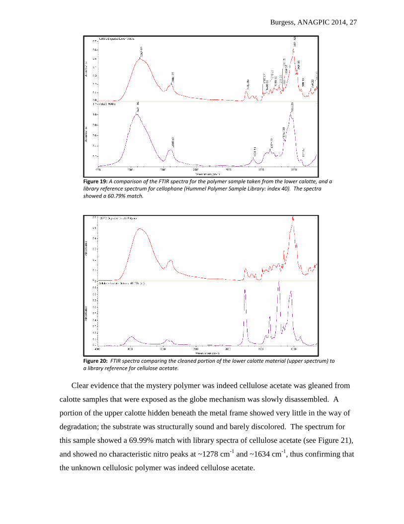
Figure 19: A comparison of the FTIR spectra for the polymer sample taken from the lower calotte, and a library reference spectrum for cellophane (Hummel Polymer Sample Library: index 40). The spectra showed a 60.79% match.
Figure 20: FTIR spectra comparing the cleaned portion of the lower calotte material (upper spectrum) to a library reference for cellulose acetate.
Clear evidence that the mystery polymer was indeed cellulose acetate was gleaned from
calotte samples that were exposed as the globe mechanism was slowly disassembled. A
portion of the upper calotte hidden beneath the metal frame showed very little in the way of
degradation; the substrate was structurally sound and barely discolored. The spectrum for
this sample showed a 69.99% match with library spectra of cellulose acetate (see Figure 21),
and showed no characteristic nitro peaks at ~1278 cm-1
and ~1634 cm-1
, thus confirming that
the unknown cellulosic polymer was indeed cellulose acetate.

Burgess, ANAGPIC 2014, 28
Figure 21: A comparison of the FTIR spectrum for the polymer sample taken from the upper calotte (Sample Reference: 1213334), with library reference spectra for Fibestos Cellulose Acetate (Gettens Collection: index 261). The spectra showed a 69.99% match.
The severely degraded light shade, shared the same characteristic markers as the calottes.
Once again the presence of triphenyl phosphate was detected by ATR on the severely
degraded outer surface. The protected inner surface of the lightshade produced a spectrum
that shared strong similarities with regenerated cellulose (see Figure 22), and thus was
identical in character to the spectra produced from the analysis of the calottes. There is a
very small carbonyl peak shown in the spectrum, but the hydroxyl peak is especially
pronounced.
Figure 22: FTIR spectra comparing the inner substrate of the lightshade material (upper spectrum) to a library reference for cellophane (Hummel Polymer Sample Library: index 40). The spectra showed a 64.54% match.

Burgess, ANAGPIC 2014, 29
The spectrum of the unknown polymer comprising the globe hemispheres confirmed the
conclusion indicated by the microchemical testing – that the polymer was cellulose nitrate.
The library spectrum for an aged sample of cellulose nitrate (IRUG Synthetic Resins: index
65) matched the spectrum of the globe material with 71.85% certainty (see Figure 23).
Visual analysis of the spectrum for the globe polymer also strongly indicates that the material
is cellulose nitrate. The strong sharp peaks at 1274.20 cm-1
and 1632.95 cm-1
are
characteristic for nitro functional groups (Shashoua 2008, 257).
Figure 23: FTIR spectra comparing the globe material (top) to a library reference for cellulose nitrate aged 63.5 years (IRUG Synthetic Resins: index 65).

Burgess, ANAGPIC 2014, 30
6.3 Analysis of the Globe Plasticizers
Py-GC-MS was used to identify the two major plasticizers in a sample of the cellulose
nitrate globe. When compared to NIST library reference spectra the two major peaks in the
pyrogram for the CN sample (see Figure 24) at 7.251-7.444 minutes and 9.491 minutes were
identified as camphor and dimethyl phthalate respectively. This finding is consistent with the
literature which shows that camphor was used as a plasticizer for CN from 1870 and that
phthalates were introduced in the early 1930s (Shashoua 2008).
Figure 24: TIC (pyrogram) for a sample of the globe substrate, showing the time intervals at which the various constituents eluted from the gas column. Significant peaks and groups of peaks are highlighted and labeled. Camphor is shown in pink, dimethyl phthalate in green and triphenyl phosphate in blue.
Both the major and minor constituents that appear in the pyrogram (figure 24) above are
outlined in Table 2. The minor compounds eluted in the first four minutes appear to
degradation products (carbon dioxide and formic acid) and pyrolysis products in the form of
analogs of furan. The range 5.610 minutes to 8.178 are all related to camphor enantiomers or
analogs of camphor (e.g. isocamphane) the latter of which could be degradation products or
impurities in the original camphor source. The strong sharp peak for dimethyl phthalate
appears at 9.491 minutes. The appearance of triphenyl phosphate at 14.383 minutes could be
misleading. While TPP was used as a plasticizer for cellulose nitrate from the 1940s
(Shashoua 2008), the source of this peak in the sample (which came from the upper portion
of the globe) is likely transference from the degraded cellulose acetate calotte that was in
direct contact with the globe when the object was received from the Buffalo Museum of
Science. The relative weakness of the TPP peak compared to the peaks attributed to camphor
and dimethyl phthalate also suggests that it was not introduced specifically as a plasticizer.

Burgess, ANAGPIC 2014, 31
Table 2: Identification of the compounds comprising the major and minor peaks shown on the pyrogram for a sample of nitrocellulose taken from the Uniclok globe material.
Time
(minutes) Compound Name
Peak
Intensity Diagram
1.285 Carbon dioxide Minor O C O
1.484 Furan Minor
O
1.576 Formic acid Minor
O
C
OH
H
3.801 2(5H) Furanone Minor
O O
4.187 Furfural Minor O
O
5.610 Isocamphane Minor
6.762 Fenchone Minor
O
6.929 Camphor Minor
O
7.135 Camphor Minor
7.251-7.444 Camphor Major
7.676 Camphor Minor
8.178 Bornanedione Minor
HO
O
9.491 Dimethyl phthalate Major CH3
CH3
O
O
O
O
14.383 Triphenyl
phosphate Minor
OO
O
P
O

Burgess, ANAGPIC 2014, 32
6.4 Analysis of the Uniclok’s Inorganic Materials
The Uniclok’s metal base was heavily oxidized, and the clock casing and calendar ring
had localized areas of wear intermitted with bright spots that had a nickel-colored luster. It
initially appeared that the object had formerly been plated, and that the metal coating had
subsequently eroded due to age, handling or overzealous polishing. X-ray Fluorescence
spectroscopy assisted in the identification of the composition of the base metal alloy, the
various decorative coatings, and the composition of the clock crystal.
Table 3: Results of the X-ray Fluorescence spectroscopic analysis of the Uniclok’s structural body. ‘M’ indicates a major constituent, ‘m’ a minor constituent and ‘t’ indicates a trace element.
Sample Site/ Number S Ca Ti M
n Fe Ni Cu Zn As Sr Ag
Calendar Ring: Shiny region
(1213288) t - - - t t m M - - t
Calendar Ring: Oxidized region
(1213283) - t - - t t m M - - t
Calendar Ring: Oxidized region
(1213677) - t t - t t M M - - t
Calendar Ring: Cleaned region
(1213678) - - - - t t M M - - t
Clock Case: Worn Region of Rear
Plate
(1213681)
- - - t t t m M - - t
Clock Case: Worn Region of Rear
Plate
(1213683)
- - - - t t m M - - t
Clock Case: Plated/ coated region of
Rear Plate (1213682) - - - - t t m M - - t
Clock Case: Worn region on top of
main body (1213691) t - - - t t m M - - t
Clock Case: Coated (nickel-colored)
region on top of main body
(1213692)
t - - - t t m M - - t
Clock Case: Coated (nickel-colored)
region on wing of main body
(1213690)
t - - - t t m M - - t
Clock Base: Silvered portion
(1213541) - - - - t t m M - - t
Clock Base: Exposed copper portion
(1213542) - - - - t t m M - - t
Clock Base: Exposed copper portion
(1213543) - - - - t t m M - - t
Calendar Ring Deposit
(1213676) - M t t M t t t t m -
Burgess, ANAGPIC 2014, 33
Table 3 shows the results of the XRF analyses of the metal alloy used to make the clock
casing and globe frame. In all samples analyzed for the clock casing, clock base and the
calendar ring, the major constituent of the metal alloy was zinc, with a consistently small
percentage of copper and a trace of nickel and silver. Although XRF is not strictly a
quantitative technique it is possible to compare relative readings of different elements
captured using the same instrumental settings (voltage, current and live time) and hardware
(tube, collimaters and filters). This is somewhat more valid when comparing two elements
that have similar molecular weights, like copper and zinc (Dr. Aaron Shugar, 2013, pers
comm), which, conveniently, were the major components of the alloy in question.
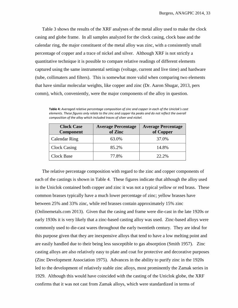
Table 4: Averaged relative percentage composition of zinc and copper in each of the Uniclok’s cast elements. These figures only relate to the zinc and copper Kα peaks and do not reflect the overall composition of the alloy which included traces of silver and nickel.
Clock Case
Component
Average Percentage
of Zinc
Average Percentage
of Copper
Calendar Ring 63.0% 37.0%
Clock Casing 85.2% 14.8%
Clock Base 77.8% 22.2%
The relative percentage composition with regard to the zinc and copper components of
each of the castings is shown in Table 4. These figures indicate that although the alloy used
in the Uniclok contained both copper and zinc it was not a typical yellow or red brass. These
common brasses typically have a much lower percentage of zinc; yellow brasses have
between 25% and 33% zinc, while red brasses contain approximately 15% zinc
(Onlinemetals.com 2013). Given that the casing and frame were die-cast in the late 1920s or
early 1930s it is very likely that a zinc-based casting alloy was used. Zinc-based alloys were
commonly used to die-cast wares throughout the early twentieth century. They are ideal for
this purpose given that they are inexpensive alloys that tend to have a low melting point and
are easily handled due to their being less susceptible to gas absorption (Smith 1957). Zinc
casting alloys are also relatively easy to plate and coat for protective and decorative purposes
(Zinc Development Association 1975). Advances in the ability to purify zinc in the 1920s
led to the development of relatively stable zinc alloys, most prominently the Zamak series in
1929. Although this would have coincided with the casting of the Uniclok globe, the XRF
confirms that it was not cast from Zamak alloys, which were standardized in terms of
F
G H
I
J
K
M
L
O
N

Burgess, ANAGPIC 2014, 34
composition and had a consistent 4% aluminum content. Aluminum was not observed in any
of the spectra.
The unknown zinc alloys used in the casting of this object could be a series of proprietary
mixes developed by the caster, who may have added copper to their zinc mixture to increase
the alloy’s corrosion resistance, strength and hardness (Smith 1957).
The noticeable variation in the zinc to copper ratios in each of the separate casting pieces
comprising the Uniclok case and frame, and within some of the castings themselves, could be
attributed to a localized surface enrichment of zinc caused by inverse segregation. This
phenomenon can be caused through the rapid cooling of a metal alloy where the component
with the lower melting temperature (in this case zinc) migrates to the surface by capillary
action through the dendritic structure of the solidified copper-rich portions of the alloy
(Habashi, 2008). In a die-casting workshop, where these clock cases were being mass-
produced, it is reasonable to assume that a quick-turnover between castings would have been
preferred, and that rapid cooling could have been a common practice.
The calendar ring and clock casing appeared to have, or have had, a silver coating. XRF
showed clear attenuation in silver peaks for worn regions of the object compared to those that
had intact shiny surfaces, as shown for the calendar ring in Figure 25.
Figure 25: XRF spectra for a worn region of the calendar ring (sample 1213289 – green spectrum) and an area that had an intact shiny luster (sample 1213288 – red spectrum). The attenuation of the green spectrum at 2.983 keV indicates a diminished presence of silver in the worn region. (Note: spectra were normalized off their Rhodium Kα peaks at~20.2 keV)
Silver plating was visually most evident in the base of the clock. After the thick layer of
corrosion was removed to reveal the surface of the object one could very clearly discern
regions with a strong silvery luster from areas of copper and dull grey zinc, likely exposed

Burgess, ANAGPIC 2014, 35
from repeated campaigns of overzealous polishing. The XRF spectra back up this
observation by showing attenuated silver peaks for the worn areas (see Figure 26).
Figure 26: XRF spectra for a region of the clock base that had an exposed copper surface (1213542 green) compared to an area that had an intact silvery lustre (1213541 red). The attenuation of the green spectrum at 2.983 keV indicates a diminished presence of silver in the worn region. (Note: spectra were normalized off their Rhodium Kα peaks at~20.2 keV)
What initially appeared to be plated nickel surfaces on the Uniclok wings and clock body
were most likely a tinted organic lacquer applied to the polished silver-plated zinc alloy.
When comparing XRF spectra for nickel colored regions of the clock casing with those of
adjacent regions of the exposed base metal there were no notable differences in composition.
Figure 27: XRF spectra for the main clock body (wings) comparing a worn region of exposed base metal (sample 1213691 - red spectrum) to a nickel colored area on the wing (sample 1213692 - green spectrum). There is no attenuation of the nickel peak at ~7.4 keV. Interestingly, L lines for silver appear to be more intense in the region of dull exposed metal. (Note: spectra were normalized off their Rhodium Kα peaks at~20.2 keV)

Burgess, ANAGPIC 2014, 36
Had there been a nickel layer deposited on the zinc alloy by some sort of electro-deposition
method, one would expect a noticeable increase in the nickel peak at 7.4 keV for the green
spectrum in figure 27. This was simply not the case. This finding fortuitously coincided
with the discovery of a Uniclok floor model on eBay in excellent condition. The photos
posted on the website showed a metal casing decorated with a shiny faux-metallic finish with
a coloring that can only be described as ‘unnatural’ (see Figure 28) and very likely the result
of a colored coating. Assuming that the advertised piece was in near original condition the
presence of a colored lacquer would neatly explain why the XRF data did not distinguish
between the nickel colored regions and the base metal.
XRF analysis revealed that the deposit on the calendar ring, which initially appeared to
be a casting flaw given that it had a patina identical in color to the surrounding metal, did in
fact have a distinctive chemical composition. The strong Kα peaks for iron and calcium
indicated that the deposit was not made from the same material as the die-cast clock case.
This finding enabled it to be successfully removed from the calendar ring by simple
mechanical cleaning.
Table 5: Results of the X-ray Fluorescence spectroscopic analysis of the Uniclok’s bezel and clock glass. ‘M’ indicates a major constituent, ‘m’ a minor constituent and ‘t’ indicates a trace element.
Sample Site/ Number Si Ca Cr Fe Cu Zn As Sr
Clock Bezel: Front (1213680) - - m - t M - -
Clock Bezel: Rear (1213679) - - m t t M - -
Clock Crystal (1213282,
1213283) M M - t - - m M
Figure 28: Images of a Uniclok Floor Model 121C found on eBay. Note the bright coloration of the die-cast clock casing and stand elements.
Burgess, ANAGPIC 2014, 37
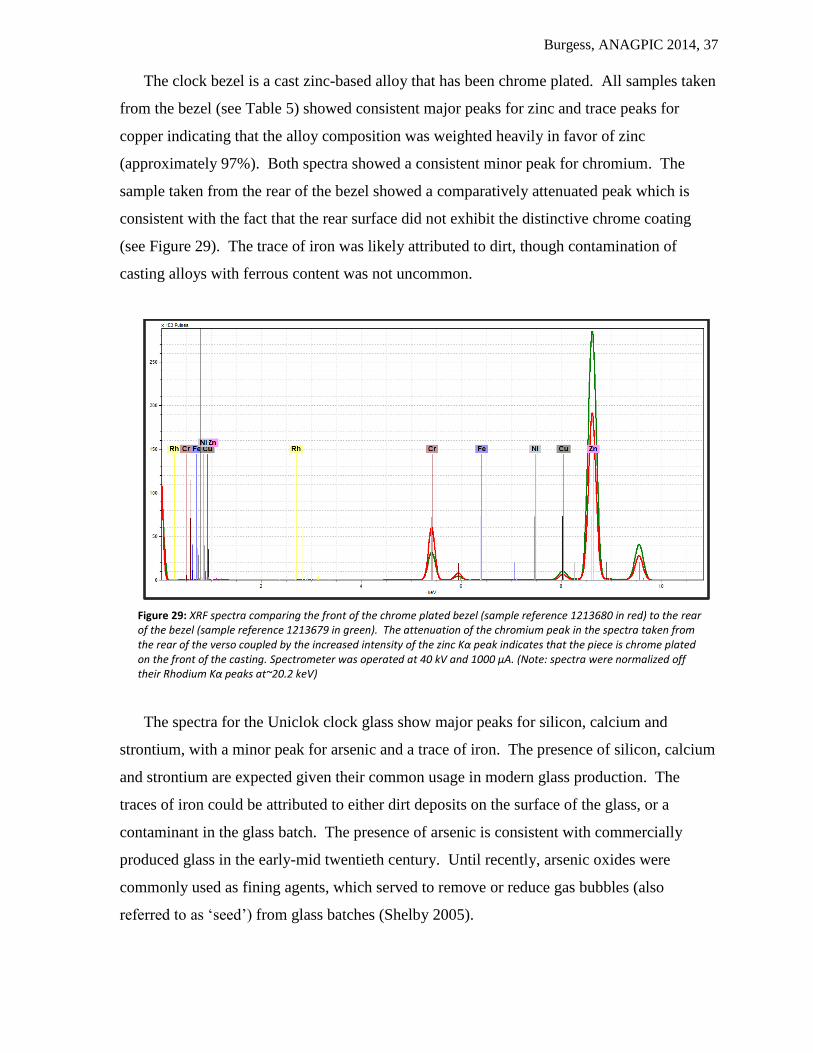
The clock bezel is a cast zinc-based alloy that has been chrome plated. All samples taken
from the bezel (see Table 5) showed consistent major peaks for zinc and trace peaks for
copper indicating that the alloy composition was weighted heavily in favor of zinc
(approximately 97%). Both spectra showed a consistent minor peak for chromium. The
sample taken from the rear of the bezel showed a comparatively attenuated peak which is
consistent with the fact that the rear surface did not exhibit the distinctive chrome coating
(see Figure 29). The trace of iron was likely attributed to dirt, though contamination of
casting alloys with ferrous content was not uncommon.
Figure 29: XRF spectra comparing the front of the chrome plated bezel (sample reference 1213680 in red) to the rear of the bezel (sample reference 1213679 in green). The attenuation of the chromium peak in the spectra taken from the rear of the verso coupled by the increased intensity of the zinc Kα peak indicates that the piece is chrome plated on the front of the casting. Spectrometer was operated at 40 kV and 1000 μA. (Note: spectra were normalized off their Rhodium Kα peaks at~20.2 keV)
The spectra for the Uniclok clock glass show major peaks for silicon, calcium and
strontium, with a minor peak for arsenic and a trace of iron. The presence of silicon, calcium
and strontium are expected given their common usage in modern glass production. The
traces of iron could be attributed to either dirt deposits on the surface of the glass, or a
contaminant in the glass batch. The presence of arsenic is consistent with commercially
produced glass in the early-mid twentieth century. Until recently, arsenic oxides were
commonly used as fining agents, which served to remove or reduce gas bubbles (also
referred to as ‘seed’) from glass batches (Shelby 2005).
Burgess, ANAGPIC 2014, 38
7. Treatment
7.1 Disassembly and Cleaning of the Clock Mechanism
The clock was disassembled using Herman E. Schulse’s Uniclok Handbook, information
contained within his patent for the globe mechanism, suggestions gleaned from online Telechron
collectors’ forums and X-radiographs of the front and side of the object.
To access the rear of the clock the back plate had to be detached by removing two screws, the
knurled ring around the power switch and unscrewing the time adjust knob by turning it in an
anti-clockwise direction. The plate was press fit on to the main clock casing. Years of corrosion
had ensured that this fit was quite tight, and the plate was unable to be moved with finger
pressure. It was eventually able to be removed by gently tapping it off with a plastic mallet.
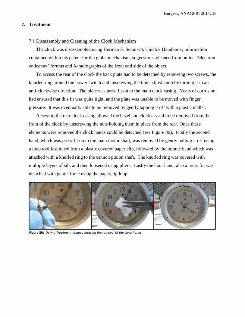
Access to the rear clock casing allowed the bezel and clock crystal to be removed from the
front of the clock by unscrewing the nuts holding them in place from the rear. Once these
elements were removed the clock hands could be detached (see Figure 30). Firstly the second
hand, which was press-fit on to the main motor shaft, was removed by gently pulling it off using
a loop tool fashioned from a plastic covered paper clip, followed by the minute hand which was
attached with a knurled ring to the cannon pinion shaft. The knurled ring was covered with
multiple layers of silk and then loosened using pliers. Lastly the hour hand, also a press fit, was
detached with gentle force using the paperclip loop.
Figure 30: During Treatment images showing the removal of the clock hands.

Burgess, ANAGPIC 2014, 39
The removal of the hands allowed the synchronous
motor to be removed from the clock casing. Unscrewing
the two machine screws holding the stator in place
allowed the coil and motor to be ejected with ease (see
Figure 31). The plate holding the dial train was then
removed from the front of the clock casing by removing
the four screws holding it in place.
The various components of the clock mechanism
including the dial train and hands were cleaned with
Stoddard solvent to reduce the accumulated grease and
grime layer. The solvent was applied with a hand-rolled cotton swab and allowed to evolve off
the surface.
Upon removal, the Telechron Type-B clock motor was found to be seized. Although there
are a lot of recommendations for cleaning Telechron motors, both published (Linz 2001) and on
enthusiast online forums, it was decided to purchase a replacement motor from a specialist.
Telechron Type-B motors are sealed oil-filled units that require an involved and quite invasive
process to recondition. The load and eventual wear on the motor, which not only powered the
clock but also the globe mechanism, would likely have required that parts of the motor be
replaced or refabricated. A replacement B-2 M-1 motor with a nine tooth pinion and a hollow
shaft was bought from David Friedlund9, a noted Telechron restorer, and installed in the Uniclok
stator.
7.2 Rewiring the Clock and Lamp
The insulation on the wiring in the clock and lamp was compromised and necessitated the
replacement of the wire in order to safely operate the instrument. Vintage two-conductor wiring
was salvaged from an old GE clock and incorporated in to the Uniclok, linking the electric
switch to the internal lamp (see Figure 32). Rayon-covered, faux-vintage, two-conductor wire
was purchased from Sundial Wire and used to replace the degraded, main power cord. The
Uniclok’s existing plug was re-wired with the replacement cord. Raychem heat-shrink rubber
tubing was used to manage the frayed ends of the brown rayon sheath (see Figure 33).
9 Dave Friedlund sells restored Telechron motors on eBay under the handle “davefr_98”. His website, www.telechronclock.com, has a wealth of information on the history of the Telechron motors, the various models and tips on their restoration.
Figure 31: The location of the two machine screws holding the stator and motor in place in the clock casing.

Burgess, ANAGPIC 2014, 40
7.3 Cleaning the Globe Hemispheres
Dirt and grime on the exterior of the globe was aqueously reduced with a 2% solution (w/v)
of triammonium citrate applied with hand-rolled cotton swabs. Potential residue was cleared
with two applications of deionized water.
7.4 Removal of the Globe Hemispheres from the Frame
The removal of the hemispheres was fraught with difficulty due to the brittleness of the
cellulose nitrate substrate. The interior of the globe was accessed per the instructions contained
in the Uniclok Handbook (Schulse 1931). The internal mechanism was heavily corroded such
that none of the brass fittings and iron set screws could be moved. This was most likely due to
the acidic environment created by the degrading cellulose nitrate globe and the cellulose acetate
light shade contained inside. The corrosion of the mechanism prevented the upper hemisphere
from being safely removed, and the position and fragility of the hemisphere prevented safe
Figure 32: Before (left) and after treatment images of the rewiring of the stator with brown two-conductor wire salvaged from a vintage GE electric clock. Note the significant degradation of the wire insulator in the image on the left.
Figure 33: Before (left) and after treatment images of the main power cord, which was replaced with a brown rayon-sheathed two conductor cord. The frayed ends of the rayon, where the sheath was removed to expose the plastic insulator, was managed with rubber heat-shrink tubing.
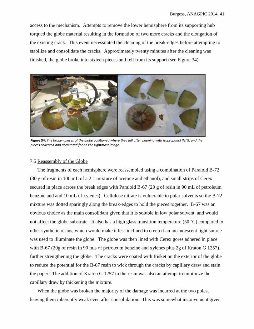
Burgess, ANAGPIC 2014, 41
access to the mechanism. Attempts to remove the lower hemisphere from its supporting hub
torqued the globe material resulting in the formation of two more cracks and the elongation of
the existing crack. This event necessitated the cleaning of the break-edges before attempting to
stabilize and consolidate the cracks. Approximately twenty minutes after the cleaning was
finished, the globe broke into sixteen pieces and fell from its support (see Figure 34)
7.5 Reassembly of the Globe
The fragments of each hemisphere were reassembled using a combination of Paraloid B-72
(30 g of resin in 100 mL of a 2:1 mixture of acetone and ethanol), and small strips of Cerex
secured in place across the break edges with Paraloid B-67 (20 g of resin in 90 mL of petroleum
benzine and and 10 mL of xylenes). Cellulose nitrate is vulnerable to polar solvents so the B-72
mixture was dotted sparingly along the break-edges to hold the pieces together. B-67 was an
obvious choice as the main consolidant given that it is soluble in low polar solvent, and would
not affect the globe substrate. It also has a high glass transition temperature (50 °C) compared to
other synthetic resins, which would make it less inclined to creep if an incandescent light source
was used to illuminate the globe. The globe was then lined with Cerex gores adhered in place
with B-67 (20g of resin in 90 mls of petroleum benzine and xylenes plus 2g of Kraton G 1257),
further strengthening the globe. The cracks were coated with frisket on the exterior of the globe
to reduce the potential for the B-67 resin to wick through the cracks by capillary draw and stain
the paper. The addition of Kraton G 1257 to the resin was also an attempt to minimize the
capillary draw by thickening the mixture.
When the globe was broken the majority of the damage was incurred at the two poles,
leaving them inherently weak even after consolidation. This was somewhat inconvenient given
Figure 34: The broken pieces of the globe positioned where they fell after cleaning with isopropanol (left), and the pieces collected and accounted for on the rightmost image.
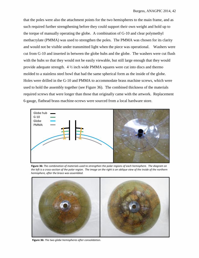
Burgess, ANAGPIC 2014, 42
that the poles were also the attachment points for the two hemispheres to the main frame, and as
such required further strengthening before they could support their own weight and hold up to
the torque of manually operating the globe. A combination of G-10 and clear polymethyl
methacrylate (PMMA) was used to strengthen the poles. The PMMA was chosen for its clarity
and would not be visible under transmitted light when the piece was operational. Washers were
cut from G-10 and inserted in between the globe hubs and the globe. The washers were cut flush
with the hubs so that they would not be easily viewable, but still large enough that they would
provide adequate strength. 4 ½ inch wide PMMA squares were cut into discs and thermo
molded to a stainless steel bowl that had the same spherical form as the inside of the globe.
Holes were drilled in the G-10 and PMMA to accommodate brass machine screws, which were
used to hold the assembly together (see Figure 36). The combined thickness of the materials
required screws that were longer than those that originally came with the artwork. Replacement
6-gauge, flathead brass machine-screws were sourced from a local hardware store.
Globe hub G-10 Globe PMMA
Figure 36: The combination of materials used to strengthen the polar regions of each hemisphere. The diagram on the left is a cross-section of the polar region. The image on the right is an oblique view of the inside of the northern hemisphere, after the brace was assembled.
Figure 36: The two globe hemispheres after consolidation.

Burgess, ANAGPIC 2014, 43
7.6 Compensating for Losses to the Globe Gores
While the globe had arrived at the Buffalo Start Art Conservation department with several
losses to the paper gores, it sustained many more when the globe was damaged. The losses were
filled with a heavy Japanese tissue toned with Golden acrylic paints. The losses were traced on
to Mylar using a fine tipped pen and transferred to the toned paper using pin pricks. The pricked
line was then torn by dragging the edge with a blunt scalpel. Each fill was applied with wheat-
starch paste and, once dry, inpainted to match the surrounding gores using Golden acrylic paints.
The fills were locally varnished with a1:1 mixture of Liquitex Soluvar gloss and matte varnishes.
With the polar regions of the globe now accessible the brown staining to the North Pole was
reduced using isopropyl alcohol applied sparingly with Q-tips.
7.7 Disassembly and Cleaning of the Globe Mechanism and Lighting Rig
If the shattering of the globe had one silver lining it was that it gave unrestricted access to the
internal mechanism. The globe’s internal mechanism was highly corroded, which complicated
its disassembly given that the many of the press-fit and threaded metal components had fused
such that they could not be easily removed.
Where possible, corrosion was superficially reduced with Renaissance Metal De-corroder,
applied with a rolled cotton swab. The gel was allowed to sit on the object for several minutes,
before the corrosion product and residual cleaner were wiped off with a cotton swab and finally
rinsed with deionized water to remove any residue of the de-corroder solution. In many cases
this enabled access to the set-screws that held the various pieces of the mechanism together.
With the larger portions of the mechanism disassembled, each individual piece could be broken
down and the corrosion further reduced with steel-wool and petroleum benzine, and/or Autosol
Polisher applied with Kimwipes and/or paper towels.
Three parts of the mechanism that were critical to the restoration of the globe’s functionality
proved the most problematic in their disassembly due to extensive corrosion. These were the
lamp socket, the irreversible worm-gear driving the rotation of the lamp-shade, and the gear
mechanism that translated the rotation of the globe to the internal mechanism. The lamp wiring
insulation was compromised and in order to make the globe safely operational it had to be
replaced. In order to access the lamp’s electrical contacts the shell cap had to be removed from
the socket. Unfortunately the screw thread connecting these two pieces was corroded and could
not be twisted open as designed. To aid in the disassembly a simple clamp was constructed from
a piece of wood by drilling a hole in it slightly larger than the diameter of the socket. The piece
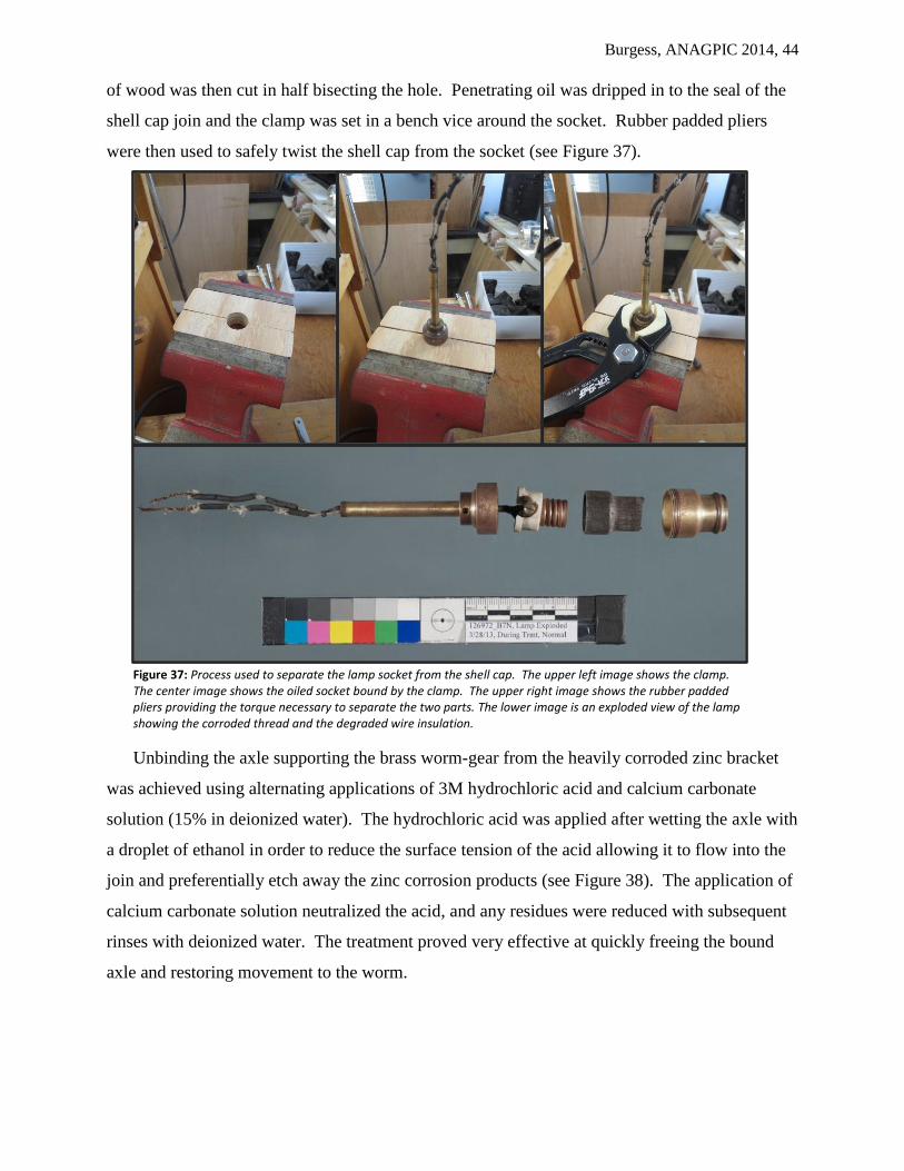
Burgess, ANAGPIC 2014, 44
of wood was then cut in half bisecting the hole. Penetrating oil was dripped in to the seal of the
shell cap join and the clamp was set in a bench vice around the socket. Rubber padded pliers
were then used to safely twist the shell cap from the socket (see Figure 37).
Unbinding the axle supporting the brass worm-gear from the heavily corroded zinc bracket
was achieved using alternating applications of 3M hydrochloric acid and calcium carbonate
solution (15% in deionized water). The hydrochloric acid was applied after wetting the axle with
a droplet of ethanol in order to reduce the surface tension of the acid allowing it to flow into the
join and preferentially etch away the zinc corrosion products (see Figure 38). The application of
calcium carbonate solution neutralized the acid, and any residues were reduced with subsequent
rinses with deionized water. The treatment proved very effective at quickly freeing the bound
axle and restoring movement to the worm.
Figure 37: Process used to separate the lamp socket from the shell cap. The upper left image shows the clamp. The center image shows the oiled socket bound by the clamp. The upper right image shows the rubber padded pliers providing the torque necessary to separate the two parts. The lower image is an exploded view of the lamp showing the corroded thread and the degraded wire insulation.

Burgess, ANAGPIC 2014, 45
Separating the globe’s upper hub/flange from the beveled gear was necessary in order to
successfully reattach the upper globe hemisphere. The protruding hub was cast with a key that
locked it in to a mortise in the collar of the beveled brass gear, thus it could not be twisted apart
using padded pliers (see Figure 39). Simple tools were once again created to facilitate the
separation. A clamp was made from a piece of wood with a bisected hole that was just wider
than the diameter of the collar of the gear. Penetrating oils were flowed into the corroded join,
and after the oil had sufficient time to soak in, the mechanism was secured in the clamp. A
wooden dowel and a mallet were used to gently tap the bound hub from the brass gear.
Figure 38: Images showing how the bound axle was freed using ethanol, hydrochloric acid, calcium carbonate and deionized water. The central image shows the acid biting the zinc bracket around the brass axle. The rightmost image shows the piece after it was rinsed in calcium carbonate and deionized water.
Figure 39: Before, during and after images of the separation of the upper hub from the beveled gear.
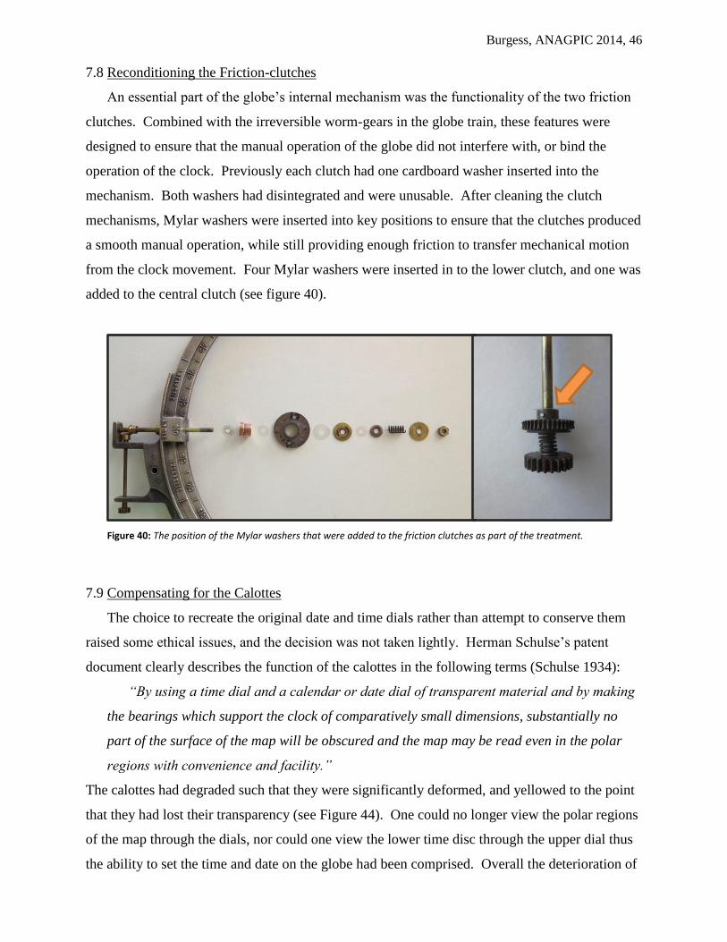
Burgess, ANAGPIC 2014, 46
7.8 Reconditioning the Friction-clutches
An essential part of the globe’s internal mechanism was the functionality of the two friction
clutches. Combined with the irreversible worm-gears in the globe train, these features were
designed to ensure that the manual operation of the globe did not interfere with, or bind the
operation of the clock. Previously each clutch had one cardboard washer inserted into the
mechanism. Both washers had disintegrated and were unusable. After cleaning the clutch
mechanisms, Mylar washers were inserted into key positions to ensure that the clutches produced
a smooth manual operation, while still providing enough friction to transfer mechanical motion
from the clock movement. Four Mylar washers were inserted in to the lower clutch, and one was
added to the central clutch (see figure 40).
Figure 40: The position of the Mylar washers that were added to the friction clutches as part of the treatment.
7.9 Compensating for the Calottes
The choice to recreate the original date and time dials rather than attempt to conserve them
raised some ethical issues, and the decision was not taken lightly. Herman Schulse’s patent
document clearly describes the function of the calottes in the following terms (Schulse 1934):
“By using a time dial and a calendar or date dial of transparent material and by making
the bearings which support the clock of comparatively small dimensions, substantially no
part of the surface of the map will be obscured and the map may be read even in the polar
regions with convenience and facility.”
The calottes had degraded such that they were significantly deformed, and yellowed to the point
that they had lost their transparency (see Figure 44). One could no longer view the polar regions
of the map through the dials, nor could one view the lower time disc through the upper dial thus
the ability to set the time and date on the globe had been comprised. Overall the deterioration of

Burgess, ANAGPIC 2014, 47
these forms had robbed them of their intended purpose, and if restoring the Uniclok’s
documented functionality was the goal then intervention was necessary.
The degraded cellulose acetate time and calendar discs were recreated from 1/16” thick
poly(methyl methacrylate) (PMMA) sheet and thermo-formed using a laboratory oven and a
spherical stainless steel mixing bowl as a mold. The PMMA was cut into circles with a band-
saw using a simple circle-jig fashioned from a piece of scrap wood, a cam clamp and a screw
(see Figure 41). A 9/16” hole was drilled in the center of each disc to accommodate the brass
rings used to attach the calottes to the central shaft of the globe mechanism. The edges of the
discs were smoothed with wet and dry abrasive papers (320 through 600 grit).
The discs were heated for two minutes in a Fisher Scientific Isotemp lab oven set to 140 °C
(the approximate glass transition temperature of PMMA), before being pressed against the outer
form of a spherical stainless steel bowl (diameter 12”). Because the form was relatively simple,
vacuum forming was not used; rather the disc was molded by hand into a shallow dome. A sheet
of felt was used as a heat insulator and also served to protect the softened acrylic from scratches
and fingerprints (see Figure 42).
Figure 41: Shaping the acrylic discs on the bandsaw with a simple jig (left), and drilling a hole in the center of the discs with a 9/16” spade bit in preparation for molding.
Figure 42: The acrylic discs were heated in a lab oven at 140 °C for 2 minutes (left) before being press formed against a stainless steel mixing bowl.

Burgess, ANAGPIC 2014, 48
The designs and indicators on the calottes were recreated digitally using Adobe Illustrator
software (see Appendix 5). The fragments of the existing calottes, drawings from the Uniclok
patent (Schulse 1931) and the technical drawing from the Albert Soeffing collection (see Figure
3) were used as visual resources for the design. The resulting image files were printed on to
Papilio clear water-slide decal paper using a Ricoh Aficio MP3500 multi-function printer/copier.
Krylon clear satin acrylic varnish was applied in a thin coat to fix the printed design to the decal
and protect it from water immersion. Water slide decals are backed with a water-activated
adhesive and a paper carrier. Applying the decals to their respective calottes was as simple as
soaking them warm water until they released from their backing paper, and then laying on them
on the surface of the PMMA dials. The decals were made from a thin film of n-butyl
methacrylate, so their plasticity allowed them to be massaged over the very slightly domed forms
(see Figure 43). As the decal adhesive dried it permanently adhered the designs to the new
acrylic supports.
Figure 43: The process of applying the water-slide decal to the formed acrylic calotte. Upper left: the printed decal, sealed with acrylic varnish, before water immersion. Upper right: the decal separating from its backing paper in a warm water bath. Lower left: the decal applied to the surface of the calotte before being massaged to form. Lower right: the finished calotte replacement.

Burgess, ANAGPIC 2014, 49
The brass hardware was removed from the original calottes and secured to the replacement
discs with small dots of Paraloid B-72 to ensure good adhesion (see Figure 44). The date disc
was drilled to accommodate two screws (for attachment to the frame) and the pinion that drove
the time disc.
The original dials were separated from the piece and kept for posterity. They were stored in
a box containing muslin bags filled with activated carbon scavengers, and A-D Strips (Image
Permanence Institute) to monitor for acetic acid emissions.
Figure 44: The original, degraded cellulose acetate calotte discs (upper image) compared to their PMMA replacements.

Burgess, ANAGPIC 2014, 50
7.10 Compensating for the Internal Shade
The original Uniclok had a ‘daylight/night discriminator’ made from cellulose acetate. This
shade reduced the transmission of the internal light source such that half of the globe would
appear in shadow, and combined with the internal rotating mechanism would indicate the
position of the Earth’s shadow in relation to the seasons. Unfortunately the shade form had
undergone severe deterioration, most likely the result of its proximity to a heat and light source,
and the fact that it was in an enclosed space where its own degradation products (acetic acid),
and that of the globe (nitrous dioxide and nitric acid) would have accelerated its decline. Once
again the functionality of the object had been compromised and compensation was required to
return the Uniclok to working order.
Information contained within the Uniclok’s patent document (US1959601) suggests that in
its original form the lamp shade would have been a translucent blue or purple (Schulse 1934).
This choice in color and light transmission allowed geographical features on the shaded side of
the globe to still be discernible. Unfortunately due to the cost of materials a translucent blue or
purple plastic could not be used in this treatment and an opaque black piece of black PMMA
sheet (1/8” in thickness) was used as an alternative.
The degraded form was recreated using a makeshift vacuum molding apparatus. The PMMA
sheet was cut to a 12” square and tacked to a wooden strainer. The plastic was heated for
twenty-five minutes in a Fisher Scientific Isotemp lab oven set to 150 °C. This was slightly
higher than the published glass transition temperature (Tg) of PMMA, but tests showed that the
sheet required a higher temperature to achieve the appropriate level of plasticity. The heated
Figure 45: The leftmost image is a drawing from the Uniclok patent indicating how the original shade might have looked. The central image shows the mold and suction platen used for the vacuum forming. The rightmost image shows the vacuum-forming in action.
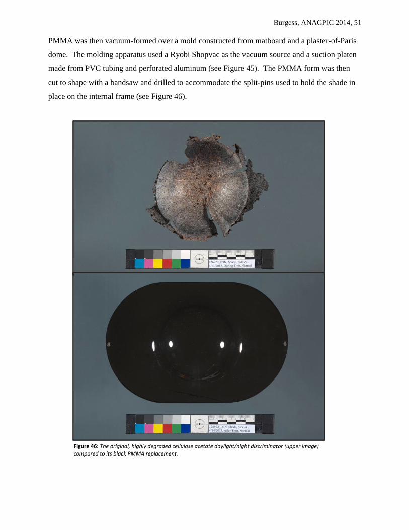
Burgess, ANAGPIC 2014, 51
PMMA was then vacuum-formed over a mold constructed from matboard and a plaster-of-Paris
dome. The molding apparatus used a Ryobi Shopvac as the vacuum source and a suction platen
made from PVC tubing and perforated aluminum (see Figure 45). The PMMA form was then
cut to shape with a bandsaw and drilled to accommodate the split-pins used to hold the shade in
place on the internal frame (see Figure 46).
Figure 46: The original, highly degraded cellulose acetate daylight/night discriminator (upper image) compared to its black PMMA replacement.
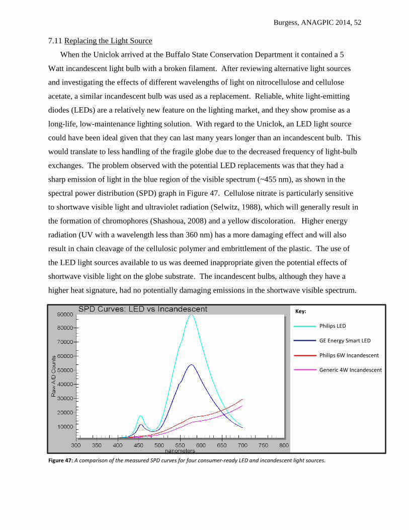
Burgess, ANAGPIC 2014, 52
7.11 Replacing the Light Source
When the Uniclok arrived at the Buffalo State Conservation Department it contained a 5
Watt incandescent light bulb with a broken filament. After reviewing alternative light sources
and investigating the effects of different wavelengths of light on nitrocellulose and cellulose
acetate, a similar incandescent bulb was used as a replacement. Reliable, white light-emitting
diodes (LEDs) are a relatively new feature on the lighting market, and they show promise as a
long-life, low-maintenance lighting solution. With regard to the Uniclok, an LED light source
could have been ideal given that they can last many years longer than an incandescent bulb. This
would translate to less handling of the fragile globe due to the decreased frequency of light-bulb
exchanges. The problem observed with the potential LED replacements was that they had a
sharp emission of light in the blue region of the visible spectrum (~455 nm), as shown in the
spectral power distribution (SPD) graph in Figure 47. Cellulose nitrate is particularly sensitive
to shortwave visible light and ultraviolet radiation (Selwitz, 1988), which will generally result in
the formation of chromophores (Shashoua, 2008) and a yellow discoloration. Higher energy
radiation (UV with a wavelength less than 360 nm) has a more damaging effect and will also
result in chain cleavage of the cellulosic polymer and embrittlement of the plastic. The use of
the LED light sources available to us was deemed inappropriate given the potential effects of
shortwave visible light on the globe substrate. The incandescent bulbs, although they have a
higher heat signature, had no potentially damaging emissions in the shortwave visible spectrum.
Figure 47: A comparison of the measured SPD curves for four consumer-ready LED and incandescent light sources.
Key:
Philips LED
GE Energy Smart LED
Philips 6W Incandescent
Generic 4W Incandescent

Burgess, ANAGPIC 2014, 53
Figure 48: After-treatment images of the front of the Uniclok. The left image shows the globe in normal illumination; the metal components have been cleaned and polished, the globe has been reassembled and cleaned, and the time and date calottes have been replaced. The image on the right showcases the restored globe’s functionality; the internal light source transmits through the globe’s translucent nitrocellulose material but is eclipsed on one side to convey the sense of the Earth’s shadow.

Burgess, ANAGPIC 2014, 54
8. Conclusions
The functionality of the Uniclok instrument, as detailed in Herman Schulse’s 1934 patent
document, was restored to working order (see Figure 48). Replacement of the degraded
electrical wiring ensured that the piece could be used safely, while the choice of a rayon sheathed
power cord, and brown two-conductor wiring was appropriate for an electrical instrument made
in the 1930s. The clock and globe dial trains were cleaned and unbound. The reconditioned
Telechron B-2 rotor provided a smooth and quiet movement, and in turn powered the reduction
train spinning the globe one revolution per day. Assuming that the flange on the lower
hemisphere maintains a tight fit with the upper hemisphere, the reduction train in the internal
mechanism will rotate the daylight/night discriminator about the incandescent light source at a
rate of one full revolution every three hundred and sixty-five days. Also consistent with its
original design, the globe and the internal shade may both now be turned manually without
impacting the clock movement. Thus the Uniclok was once again able to provide accurate time
and date information while simulating daylight and night as they exist at a given point in time.
Cleaning and polishing the clock casing, clock base, calendar ring and globe frame
significantly improved the appearance and cleanliness of the object, although it exposed a history
of over-cleaning especially to the silvered base. Sealing the polished metal decreased the
oxidation potential of the metal surfaces, and in turn helped to reduce the maintenance of the
object on-going.
Compensation for the highly degraded cellulose acetate components of the Uniclok was
successful both in terms of restoring lost functionality and improving the overall appearance of
the globe. The replacement time and date dials, and daylight/night discriminator, fabricated in
PMMA, fulfilled the functionality described in Herman Schulse’s Uniclok patent document; the
map details at the North Pole could be read through the stacked time and date dials, the time dial
could be read through the date dial, and the black light shade cast an appropriate shadow on half
of the globe at any one time. Transferring the digitally reconstructed calotte markings to the
calottes using water slide decals allowed them to be finely rendered, accurately reproducing the
look and feel of the commercially printed cellulose acetate dials. The techniques used to
fabricate these replacement parts proved that simple plastic forms could be safely reconstructed
in a conservation lab setting, and produced at low cost.
Scientific analysis of the Uniclok materials helped to uncover some of the manufacturing
history of the globe, and its processes of deterioration. The major structural components of the
object were identified as a zinc-rich casting alloy using XRF. This was neatly married to the
Burgess, ANAGPIC 2014, 55
Sterling Die-casting Co.’s maker’s mark giving clear evidence of how and where the metal parts
of the object were created. The identification of the degraded plastics demonstrated how the by-
products of their decay had had a deleterious effect on the globe’s materials. This included not
only the autocatalytic deterioration of the cellulose acetate components, but the heavy corrosion
of the internal mechanism and electrical wiring.
The damage incurred by the globe during treatment was unfortunate, and ultimately detracted
from the overall experience of the globe given that the number of cracks visible with transmitted
light increased over the course of treatment. The breakage did however provide a valuable
lesson and some additional treatment opportunities. Had the globe not broken it is doubtful that
the internal mechanism could have been successfully reconditioned and documented. Certainly
the fabrication of the time and date dials would not have been possible with the globe
hemispheres in place, and finding a solution to mend the globe that considered cellulose nitrates’
sensitivities would not have been required. All of these activities were important learning
experiences that leveraged two years of study and practice at the Buffalo State Art Conservation
program.
9. Future Research
To fully determine the original appearance of the Uniclok object closer attention needs to be
paid to the nickel colored regions of the clock casing. While analyzing and cleaning these parts
of the object suspicions were raised that they may have been the result of an organic coating
applied either over the finished metal, rather than an electro-deposited nickel coating. This needs
to be investigated further. The coating has been eroded by cleaning, and some areas have been
stripped to the base metal. Subsequent treatments, if not conducted with care, could erase all
evidence of this decorative layer and cause a dramatic departure from the object’s intended
finish. A sample of the suspected coating could be taken from the clock adjustment dial10
on the
rear of the Uniclok and analyzed with transmission FTIR microscopy, or GC-MS.
10
This dial was intentionally left in its original state, and was neither cleaned nor sealed in wax or Agateen lacquer.
Burgess, ANAGPIC 2014, 56
10. Acknowledgements
Buffalo State College Art Department
Jonathan Thornton, Professor and advisor, Objects Conservation
Dr. Corina Rogge, Andrew W. Mellon Professor in Conservation Science
Dr. Aaron Shugar, Professor, Conservation Science
Judith Walsh, Professor, Paper Conservation
James Hamm, Professor, Paintings Conservation
Jiuan Jiuan Chen, Professor, Examination and Documentation
Lucy Skinner, Mellon Teaching Fellow, Objects Conservation
Patrick Ravines, Director and Associate Professor
Thanks to every member of the Buffalo State faculty, without whose advice and support I could
never have completed this project.
Assistance Researching the History and Significance of the Uniclok Object
Dr. F. Christopher Tahk, Professor/Director Emeritus, Conservation Science
Chris’ advice, vast knowledge and endless willingness to help were an inspiration throughout this
project.
Advice on Globe Restoration
T.K McClintock, Owner and Chief Conservator, Studio TKM
Winterthur Library
Debra Hess-Norris, Director WUDPAC Program
Jeanne Solensky, Winterthur Librarian, Joseph Downs Collection of Manuscripts and Printed
Ephemera
Burgess, ANAGPIC 2014, 57
11. References
11.1 Published References Cited
Aked, Charles K. “Coup D’Oeile Electric Clocks or Collectelectric”, NAWCC Bulletin,
vol.28:6, no.245, 1986, pp.474-484.
Baier, Joseph G, and James L. Tigner and Marvin E. Whitney. Questions and Answers of and
for the Clock Making Profession, American Watchmakers Institute Press, Cincinnati, OH, 1981
De Carle, Donald, Watch and Clock Encyclopedia, Bonanza Books, New York, NY, 1977
Chiavari, G and D. Fabbri, G.C. Galletti, S. Prati and N. Scianna: “Use of Pyrolysis-Gas
Chromatography/Mass Spectrometry to Characterise Binding Media and Protectives From a
Coronelli’s Terrestrial Globe”, Journal of Cultural Heritage, Vol:7, 2006, pp.67-70
Funk & Wagnalls Company. "Uniclok Advertisement." The Literary Digest (Nov 14, 1931): p.47
Habashi, Fathi. Alloys : Preparation, properties, applications. John Wiley & Sons, New York,
2008
Holcomb III, Harry S., and Robert Webb, “The Warren Telechron Master Clock Type A”,
NAWCC Bulletin, vol. 27:1, no. 234, 1985, pp.35–37
Library of Congress Copyright Office, Catalogue of Copyright Entries. Part 1. Books, Group 2.
New Series, Volume 28, For the Year 1931, Nos. 1-12, United States Government Printing Office,
Washington DC, 1932, p.998
Linz, Jim. Electrifying time : Telechron and GE clocks, 1925-55, Atglen, PA: Schiffer Pub,
2001.
Littlejohn, D; , R.A; Pethrick, A; Quye, and J.A Ballany. "Investigation of the degradation of
cellulose acetate museum artefacts." Polymer Degradation and Stability no. 97 (11):9, 2012
National Geographic Society, “Advertisement for Uniclok”, The National Geographic Magazine
: November 1930, Vol 58: 5, unnumbered advertising page.
Shashoua, Yvonne. Conservation of Plastics : Material science, degradation and preservation,
Butterworth Heinemann, Oxford, UK, 2008
Schulse, Herman E. 1931. Terrestrial Globe Frame and Clock Casing. US Patent Des.84,794,
filed April 11th
, 1931, and issued August 4th
1931.
Schulse, H.E. The Earth : Uniclok Globe Handbook : A Pocket Manual of the Earth, Moon, Sun,
Planets, Stars and…. , Universal Clock and Globe Corporation, Wilmington, DE, 1931.
Schulse, Herman E. 1934. Chronological Instrument. US Patent 1,959,601, filed September 19th
,
1931, and issued May 22nd
1934.
Burgess, ANAGPIC 2014, 58
Selwitz, Charles M. 1988. Cellulose Nitrate in Conservation : Research in Conservation 2. Marina
del Ray, CA: The Getty Conservation Institute.
Shelby, J.E. 2005. Introduction to Glass Science and Technology. Cambridge, UK: The Royal
Society of Chemistry
Smith, H.L. “Chapter 41 : Zinc-Base Alloys”, Cast Metals Handbook : Fourth Ed., American
Foundrymen’s Society, Des Plaines, IL, 1957.
Warren, Henry E. 1922. Self Starting Synchronous Motor. US Patent 1,283,432, filed
December 26th, 1916, and issued October 29th
, 1918.
Warren, Henry E. 1922. Lubricating System. US Patent 1,430,867, filed September 1st, 1920,
and issued October 3rd
, 1922.
Zinc Development Association., and Zinc Alloy Die Casters Association. Zinc die casting guide
: a handbook for designers using zinc die castings. Zinc Development Association, London,;
1975
11.2 Online References Cited
Antique Clocks, “Antique Globe Clock Company Clock”, www.antiqueclockspriceguide.com,
accessed February 21st 2013: <www.antiqueclockspriceguide.com/pages/clock6919.php>
Antique Clocks, “Timby Antique Clock”, www.antiqueclockspriceguide.com, accessed February
21st 2013: <www.antiqueclockspriceguide.com/pages/clock9271.php>
Cottone Auctions, “Rare Juvet Globe Table Top Clock”, www.cottoneauctions.com, accessed
February 21st 2013:
<www.cottoneauctions.com/displayItem.php?displayItem_id=1336>
eBay, “4 Photos 8 x 10 Sterling Die Casting Co Building & Interiors Upstate NY c1930”,
www.ebay.com, accessed March 25th
2013:
<www.ebay.com/itm/4-Photos-8-x-10-Sterling-Die-Casting-Co-Building-Interiors-Upstate-NY-
c1930-/300838543063>
National Museum of American History, “Juvet Time Globe”, americanhistory.si.edu, accessed
February 21st 2013: <americanhistory.si.edu/collections/search/object/nmah_1203340>
Onlinemetals.com, “The Online Metals Guide to Brass”, www.onlinemetals.com, accessed
March 17th
2013:
<http://www.onlinemetals.com/brassguide.cfm>
Schultz, Mike. “Telechron Model 700 ‘Electrolarm’ Clock”, www.uv201.com, accessed February
24th
2103: <uv201.com/Clock_Pages/Telechron/electrolarm.htm>
Tague, Ace. “Rare Art Deco UNICLOK World Globe Floor Clock Circa 1930 Telechron
Illuminated”, www.ebay.com, accessed March 21st 2013:
Burgess, ANAGPIC 2014, 59
< http://www.ebay.com/itm/Rare-Art-Deco-UNICLOK-World-Globe-Floor-Clock-Circa-1930-
Telechron-Illuminated-/380610454791?pt=LH_DefaultDomain_0&hash=item589e26a507>
Unknown, “Clocks by Warren Clock Co.”, www.clockhistory.com, accessed October 28th 2012.
<clockhistory.com/telechron/warrenclockco/index.html>
Urban Remains Chicago, “Rare c. 1930's reverse painted art deco illuminated ad clock with milk
glass panels”, www.urbanremainschicago.com, accessed March 17th
2013:
<www.urbanremainschicago.com/rare-c-1930-s-reverse-painted-art-deco-illuminated-ad-clock-
with-milk-glass-panels.html>
The Winterthur Library, “The Joseph Downs Collection of Manuscripts and Printed Ephemera”,
www.winterthur.org, accessed October 20th
2012:
<http://findingaid.winterthur.org/html/HTML_Finding_Aids/COL0774.htm>
11.3 Published References Consulted
Ammen, C.W. The Metalcaster’s Bible : A Complete and Practical Guide to Metalcasting! Tab
Books Inc., Blue Ridge Summit, PA, 1980.
Baier, Joseph G., James L. Tigner, and Marvin E. Whitney. Questions and answers of and for the
clockmaking profession. American Watchmakers Institute Press. Cincinnati, OH, 1981.
Grissom, Carol A. Zinc sculpture in America 1850-1950. University of Delaware Press, Newark,
DE, 2009.
Tyler, E. J. The craft of the clockmaker. Crown Publishers, New York, NY, 1974.
Whiten, Anthony J. Repairing Old Clocks and Watches, NAG Press Ltd, London, UK, 1982.

Burgess, ANAGPIC 2014, 60
12. Materials and Sources
ACRYLIC SHEET 1/8” black polymethyl methacrylate. Supplied by Great Lakes Plastic: 2371
Broadway St Buffalo, NY 14212. Ph: (716) 896-3100 Web: www.greatlakesplastic.com
ACRYLIC SHEET 1/16” clear polymethyl methacrylate. Found in Buffalo State Art
Conservation workshop. Supplier unknown.
AGATEEN AIR DRY LACQUER #27 - cellulose nitrate based lacquer. Agate Lacquer Tri-Nat,
LLC, 824 South Avenue Middlesex, NJ 08846, Ph: 732- 968-1080. Available from Talas 330
Morgan Ave Brooklyn, NY 11211; Ph: 212-219-0770.
AGATEEN AIR DRY LACQUER THINNER #1 – proprietary mix of toluol, n-butyl alcohol, n-
amyl acetate , n-Butyl acetate, n-Propyl acetate. Agate Lacquer Tri-Nat, LLC, 824 South
Avenue Middlesex, NJ 08846, Ph: 732- 968-1080. Available from Talas 330 Morgan Ave
Brooklyn, NY 11211; Ph: 212-219-0770.
ARM AND HAMMER SUPER WASHING SODA: solution of sodium carbonate in deionized
water (15% w/v). Purchased from Wegmans.
AUTOSOL METAL POLISH. Autosol LLC, P.O. Box 340358, Austin, TX 78734. Ph: 1800-
314-5545. Web: http://autosol.com.
BROWN, 2 CONDUCTOR, 18-GAUGE, PVC-INSULATED, RAYON-COVERED WIRE,
Sundial Wire, PO Box 803, Northhampton, MA 01061. Ph: 413.582.6909. Web:
www.sundialwire.com.
BUTCHER’S BOWLING ALLEY WAX (CLEAR) - a blend of carnauba and microcrystalline
waxes with mineral spirits as a softening agent. Available from Conservation Support Systems,
P.O. Box 91746, Santa Barbara, CA 93190. Ph: 1800-482-6299. Web:
www.conservationsupportsystems.com
CEREX (spun bonded nylon, 0.4 oz./sq. yd.) Talas 330 Morgan Ave Brooklyn, NY 11211; 212-
219-0770
GREEN FELT, Vintage Wire and Supply, 416 Milan Avenue P.O. Box 864, Amherst, OH
44001. Web: http://vintagewireandsupply.com
KRATON G 1257 (copolymer of polystyrene and poly(ethylene butylene) Shell Chemical Co.,
1415 West 22nd St., Oak Brook, Illinois 60522-9008. available from Talas 330 Morgan Ave
Brooklyn, NY 11211; 212-219-0770
LIQUITEX SOLUVAR GLOSS PICTURE VARNISH (a mixture of n-butyl and isobutyl
methacrylates) Binney & Smith Inc., Easton, PA 18044.
LIQUITEX SOLUVAR MATTE PICTURE VARNISH (a mixture of n-butyl and isobutyl
methacrylates) Binney & Smith Inc., Easton, PA 18044.
MYLAR Type D [clear] (polyester film), 5 mil thick (1 mil = .001") now known as Mitsubishi
Hostaphan 43SM or Dupont Melinex type 516 or 456, since the brand Mylar-D has been
Burgess, ANAGPIC 2014, 61
discontinued as of 2001; available from Talas 330 Morgan Ave Brooklyn, NY 11211; 212-219-
0770.
PAPILIO CLEAR LASER DECAL PAPER. n-Butyl methacrylate, self-adhesive, water-slide
decals. HPS Papilio, P.O. Box 855 Rhome, TX 76078. Ph: 940-627-0112. Web:
www.papilio.com
PARALOID B-67 (isobutyl methacrylate) Rohm & Haas, Philadelphia, PA.
PARALOID B-72 (a copolymer of ethylmethacrylate and methyl acrylate) Rohm & Haas,
Philadelphia, PA.
PHILIPS 6W CLEAR S6 INDICATOR BULB. Acquired from Home Depot, 2100 Elmwood
Ave, Buffalo, NY 14207. Ph: 716-871-8800. Web: www.homedepot.com.
PRECIPITATED CHALK – precipitated calcium carbonate. L. Cornelissen & Sons, 105 Great
Russell St, London, United Kingdom. Ph: +44 020 7636 1045. Web: www.cornelissen.com
RAYCHEM HEAT-SHRINK TUBING, Tyco Electronics Corporation, 300 Constitution Drive,
Menlo Park, CA 94025-1164. Ph: 650-361-3333
RENAISSANCE METAL DE-CORRODER: An amine complex of hydro-oxycarboxilic acid in
aqueous solution. Available from Talas. 330 Morgan Ave, Brooklyn, NY 11211; Ph: 212-219-
0770.
RHOPLEX N-580 ([butyl acrylate homopolymer] emulsion) Rohm & Haas, Philadelphia, PA.
Available from Talas 330 Morgan Ave Brooklyn, NY 11211; Ph: 212-219-0770.
TELECHRON B-2 M-1 ROTOR – Reconditioned Telechron B-2M-1 rotor - disassembled,
cleaned, rebushed and lubricated by David Friedlund, 36006 SW Bald Peak Rd, Hillsboro, OR,
97123. Web: www.telechronclock.com.

Burgess, ANAGPIC 2014, 62
13. Autobiographical Statement
Aaron Burgess received a Bachelor’s of Fine Arts from the Elam School of Fine Arts,
University of Auckland, where he studied painting, art theory, and art history. After graduating
in 1999 he started a ten year career in information technology. It was not until 2009 that Aaron
opted to pursue art conservation. He interned at the Denver Art Museum (DAM) for nine
months before taking on a role as a conservation technician the following year, all the while
completing chemistry courses at the University of Colorado, Denver. While at DAM he had the
opportunity to survey and treat a broad range of materials and artworks including Native
American textiles and beadwork, pre-Columbian burial ceramics, WPA era paintings and murals
and variable media installations. Aaron’s primary interests are in modern and contemporary
materials, and media preservation. In the summer of 2012 he interned at the Detroit Institute of
Arts treating objects in their modern and contemporary collection, and also surveying pieces in
their variable media collection. Aaron will complete a graduate internship at The Henry Ford
Museum from September 2013 through September 2014. He will receive his Master of Arts and
Certificate of Advanced Study in Art Conservation, specializing in objects conservation, from
Buffalo State College in September 2014.

Burgess, ANAGPIC 2014, 63
14. List of Illustrations
Figures in Text
1. National Geographic advertisement clipping for Uniclok. Image source: The National
Geographic Magazine – November 1930. Vol. 58: 5.
2. Literary Digest advertisement for Uniclok. Image Source: Literary Digest - Nov 14, 1931,
p.47
3. Uniclok desk model compared to sketch from Winterthur Library Collection. Image source:
personal correspondence with Jeanne Solensky, Winterthur Librarian and custodian of the
Downs Collection of Printed Ephemera.
4. Uniclok images from original patent. Image Source: Schulse, Herman E. Chronological
Instrument. US Patent 1,959,601, filed September 19th
, 1931, and issued May 22nd
1934.
5. Louis P. Juvet and Company, Tabletop Clock, c.1880. Image source:
<www.cottoneauctions.com/images/auction/2009-08-29/0618juvet.jpg>
6. Theodore Timby, Solar Clock, 1864. Image source:
<www.antiqueclockspriceguide.com/pages/clock9271.php>
7. LaPorte Hubbell, Globe Clock, c.1883. Image source:
<www.antiqueclockspriceguide.com/pages/clock6919.php>
8. Image from US Patent for Warren’s self-starting synchronous clock motor. Image source:
Linz, p.17.
9. A Telechron Model 700 “Electrolarm”. Image source:
<collections.thehenryford.org/CYOE_Image.aspx?objectKey=232798>. Accessed October
22nd
2014.
10. Sterling Die-casting Co.’s maker’s mark inset with three images of Sterling Die-Casting Co.
taken in December 1930. Image source: <www.ebay.com/itm/4-Photos-8-x-10-Sterling-Die-
Casting-Co-Building-Interiors-Upstate-NY-c1930-/300838543063>. Accessed March 25th
2013.
11. Schulse’s design patents related to clock cases and globe fixtures produced by the Universal
Clock and Globe Corp. Image source: Google patents (patent IDs: Des84,795, Des84,796,
Des85,206, Des85,207, Des86,937).
12. The Telechron Type B coil, or 'stator', removed from the Uniclok owned by the Buffalo
Museum of Science.

Burgess, ANAGPIC 2014, 64
13. An accessory image of clock parts removed from the Uniclok owned by the Buffalo Museum
of Science; a Telechron Type-B synchronous motor, the hour wheel, the hour hand, the
center wheel, the knurled ring, the minute hand, and the second hand.
14. A visual breakdown of the dial train removed from the Uniclok owned by the Buffalo
Museum of Science.
15. An annotated selection of images of the lower drive train that controls the rotation of the
globe’s lower hemisphere.
16. An annotated selection of images of the internal drive train that controls the rotation of the
globe’s daylight/night discriminator.
17. Images of the two friction clutches that allow the globe and daylight/night discriminator to be
manually rotated independently from the clock.
18. FTIR spectra comparing a sample of the degradation product taken from the Uniclok calotte
with a library reference (NIST Chemical Webbook) spectrum for triphenyl phosphate.
19. FTIR spectra comparing a degraded sample of the Uniclok’s lower calotte with a library
reference (Hummel Polymer Sample Library) spectrum for cellophane.
20. FTIR spectra comparing a degraded sample of the Uniclok’s lower calotte with a library
reference spectrum for cellulose acetate.
21. FTIR spectra comparing a relatively intact sample of the Uniclok’s upper calotte with a
library reference spectrum (Gettens Collection) for Fibestos cellulose acetate.
22. FTIR spectra comparing a sample of the Uniclok light shade with a library reference
spectrum for cellophane.
23. FTIR spectra comparing a sample of the globe polymer with a library reference spectrum
(IRUG Synthetic Resins) for cellulose nitrate.
24. GC-MS TIC (pyrogram) for a sample of the Uniclok globe substrate, showing its various
constituent compounds including the plasticizers used to make the cellulose nitrate polymer.
25. XRF spectra comparing a worn region of the Uniclok calendar ring to an area that had an
intact shiny luster. The spectra indicate that the calendar ring is silver coated.
26. XRF spectra comparing a worn region of the Uniclok base to an area that had an intact shiny
luster. The spectra indicate that the base is silver coated.
27. XRF spectra comparing a worn region of the Uniclok clock casing to an area that had a
nickel coloring. The spectra indicate that the clock casing is not nickel plated.
Burgess, ANAGPIC 2014, 65
28. Images of a Uniclok Floor Model 121C. Image source: <www.ebay.com/itm/Rare-Art-
Deco-UNICLOK-World-Globe-Floor-Clock-Circa-1930-Telechron-Illuminated-
/380610454791?pt=LH_DefaultDomain_0&hash=item589e26a507>
29. XRF spectra comparing the relative peak intensities as seen from the front and verso of the
clock bezel. The spectra indicate that the bezel is chrome coated
30. Treatment images showing the removal of the clock hands.
31. The inside of the rear of the clock casing.
32. Before and after treatment images of the rewiring of the clock stator.
33. Before and after treatment images of the frayed, original power cord and its replacement.
34. During-treatment shots of the globe after it fractured into sixteen pieces.
35. During-treatment images showing how the fragile pole regions of the globe were structurally
supported.
36. During-treatment images of the globe hemispheres after consolidation.
37. During-treatment images detailing the process of separating the shell cap from the socket of
the internal lamp fixture.
38. During-treatment images showing how a bound axle was freed using ethanol, hydrochloric
acid, calcium carbonate and deionized water.
39. During-treatment images showing how a bound gear was separated from the upper globe
hub.
40. During-treatment images showing the position Mylar washers inserted in to the globe’s
friction clutches.
41. During-treatment images outlining the process of shaping the replacement time and date
calottes.
42. During-treatment images outlining the process of thermoforming the replacement time and
date calottes.
43. During-treatment images detailing the process of applying the digitally recreated calotte
designs to the replacement calottes.
44. Before and after treatment images of the original degraded cellulose acetate calottes and their
polymethyl methacrylate replacements.
45. During-treatment images outlining the process of vacuum-forming the replacement internal
lightshade.
46. Before and after treatment images of the original degraded cellulose acetate lightshade and
its toned polymethyl methacrylate replacement.
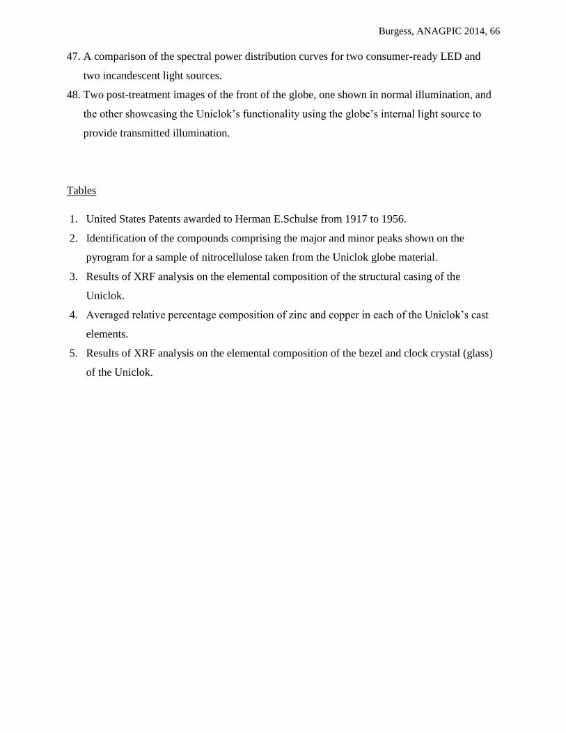
Burgess, ANAGPIC 2014, 66
47. A comparison of the spectral power distribution curves for two consumer-ready LED and
two incandescent light sources.
48. Two post-treatment images of the front of the globe, one shown in normal illumination, and
the other showcasing the Uniclok’s functionality using the globe’s internal light source to
provide transmitted illumination.
Tables
1. United States Patents awarded to Herman E.Schulse from 1917 to 1956.
2. Identification of the compounds comprising the major and minor peaks shown on the
pyrogram for a sample of nitrocellulose taken from the Uniclok globe material.
3. Results of XRF analysis on the elemental composition of the structural casing of the
Uniclok.
4. Averaged relative percentage composition of zinc and copper in each of the Uniclok’s cast
elements.
5. Results of XRF analysis on the elemental composition of the bezel and clock crystal (glass)
of the Uniclok.
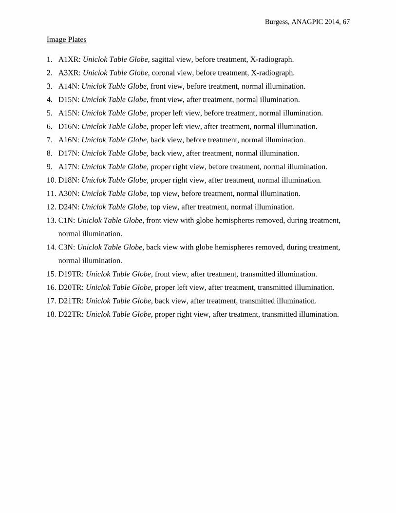
Burgess, ANAGPIC 2014, 67
Image Plates
1. A1XR: Uniclok Table Globe, sagittal view, before treatment, X-radiograph.
2. A3XR: Uniclok Table Globe, coronal view, before treatment, X-radiograph.
3. A14N: Uniclok Table Globe, front view, before treatment, normal illumination.
4. D15N: Uniclok Table Globe, front view, after treatment, normal illumination.
5. A15N: Uniclok Table Globe, proper left view, before treatment, normal illumination.
6. D16N: Uniclok Table Globe, proper left view, after treatment, normal illumination.
7. A16N: Uniclok Table Globe, back view, before treatment, normal illumination.
8. D17N: Uniclok Table Globe, back view, after treatment, normal illumination.
9. A17N: Uniclok Table Globe, proper right view, before treatment, normal illumination.
10. D18N: Uniclok Table Globe, proper right view, after treatment, normal illumination.
11. A30N: Uniclok Table Globe, top view, before treatment, normal illumination.
12. D24N: Uniclok Table Globe, top view, after treatment, normal illumination.
13. C1N: Uniclok Table Globe, front view with globe hemispheres removed, during treatment,
normal illumination.
14. C3N: Uniclok Table Globe, back view with globe hemispheres removed, during treatment,
normal illumination.
15. D19TR: Uniclok Table Globe, front view, after treatment, transmitted illumination.
16. D20TR: Uniclok Table Globe, proper left view, after treatment, transmitted illumination.
17. D21TR: Uniclok Table Globe, back view, after treatment, transmitted illumination.
18. D22TR: Uniclok Table Globe, proper right view, after treatment, transmitted illumination.

Burgess, ANAGPIC 2014, 68
Pla
te 2
: C
oro
na
l vie
w, b
efo
re t
rea
tmen
t, X
-ra
dio
gra
ph
. P
late
1:
Sag
itta
l vie
w, b
efo
re t
rea
tmen
t, X
-ra
dio
gra
ph

Burgess, ANAGPIC 2014, 69
Pla
te 4
: F
ron
t, a
fter
tre
atm
ent,
no
rma
l illu
min
ati
on
Pla
te 3
: F
ron
t, b
efo
re t
rea
tmen
t, n
orm
al i
llum
ina
tio
n

Burgess, ANAGPIC 2014, 70
Pla
te 6
: P
rop
er le
ft, a
fter
tre
atm
ent,
no
rma
l illu
min
ati
on
Pla
te 5
: P
rop
er le
ft, b
efo
re t
rea
tmen
t, n
orm
al i
llum
ina
tio
n
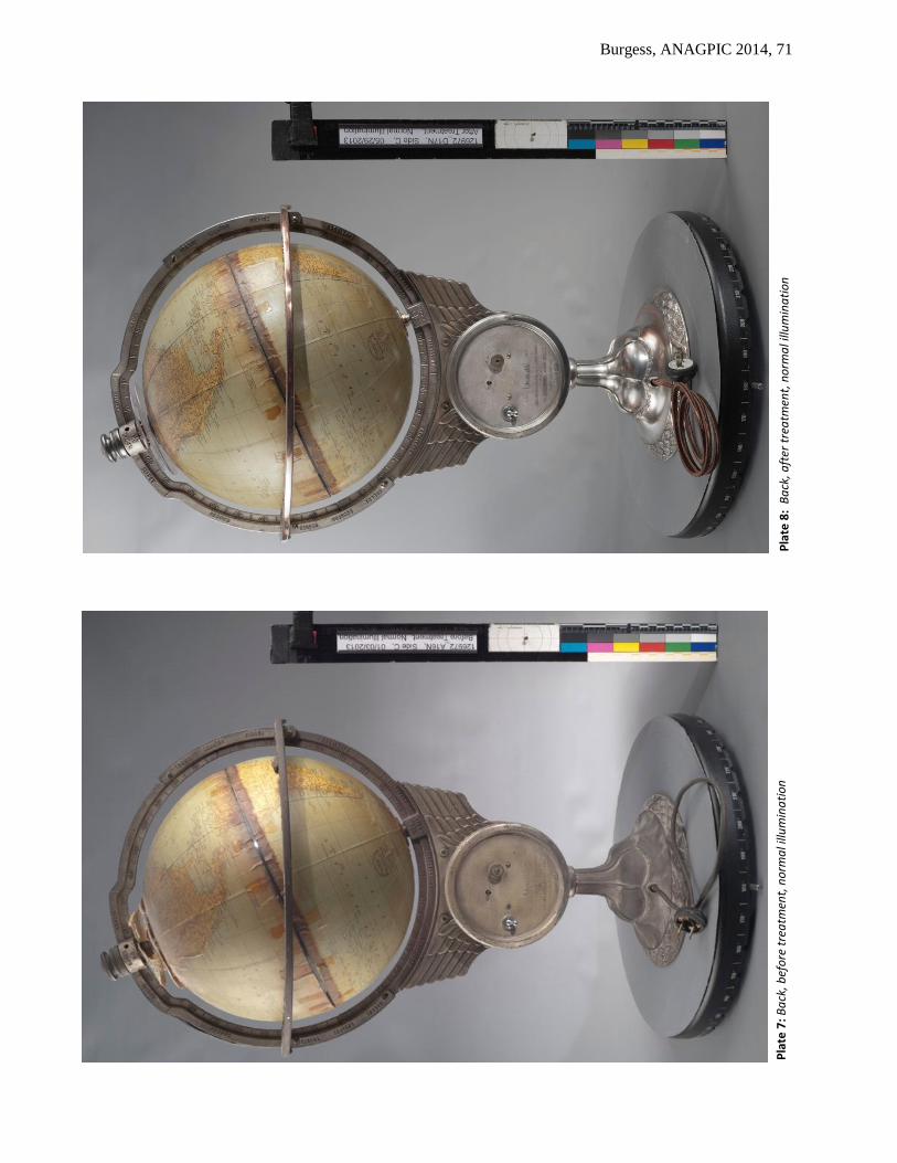
Burgess, ANAGPIC 2014, 71
Pla
te 8
: B
ack
, aft
er t
rea
tmen
t, n
orm
al i
llum
ina
tio
n
Pla
te 7
: B
ack
, bef
ore
tre
atm
ent,
no
rma
l illu
min
ati
on
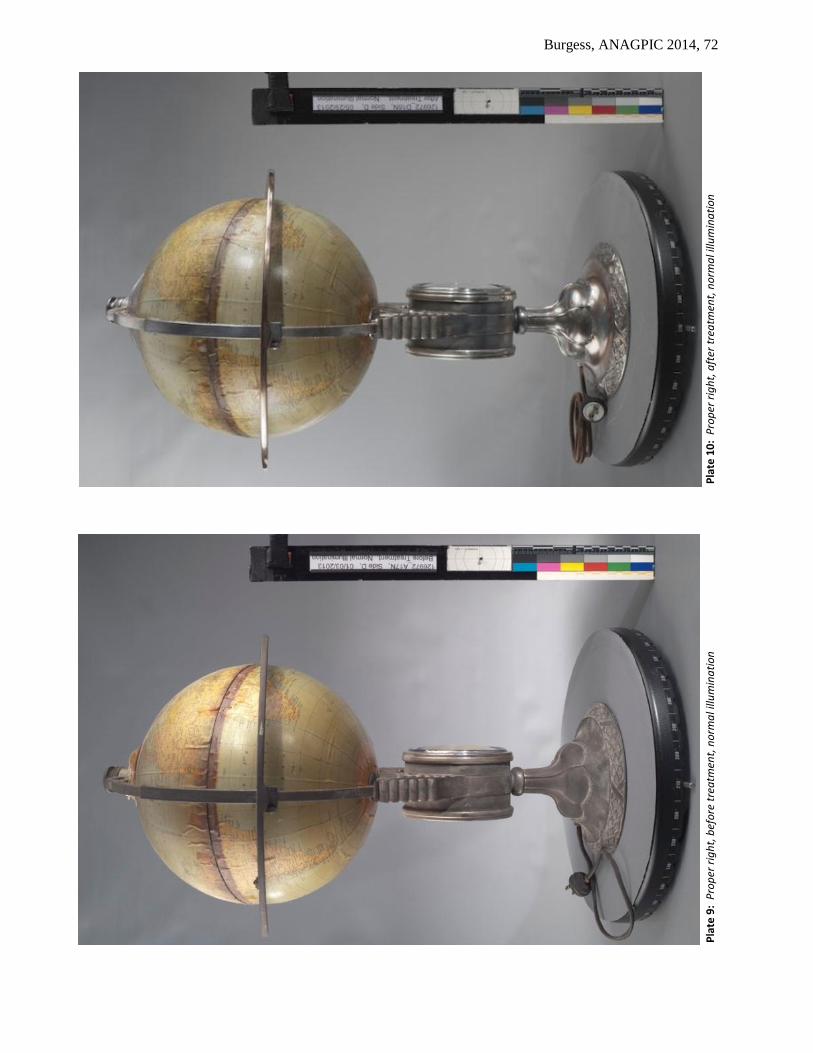
Burgess, ANAGPIC 2014, 72
Pla
te 1
0:
Pro
per
rig
ht,
aft
er t
rea
tmen
t, n
orm
al i
llum
ina
tio
n
Pla
te 9
: P
rop
er r
igh
t, b
efo
re t
rea
tmen
t, n
orm
al i
llum
ina
tio
n

Burgess, ANAGPIC 2014, 73
Plate 11: Top, before treatment, normal illumination
Plate 12: Top, after treatment, normal illumination

Burgess, ANAGPIC 2014, 74
Pla
te 1
4:
Ba
ck w
ith
glo
be
hem
isp
her
es r
emo
ved
, du
rin
g t
rea
tmen
t, n
orm
al
illu
min
ati
on
Pla
te 1
3:
Fro
nt
wit
h g
lob
e h
emis
ph
eres
rem
ove
d, d
uri
ng
tre
atm
ent,
no
rma
l ill
um
ina
tio
n
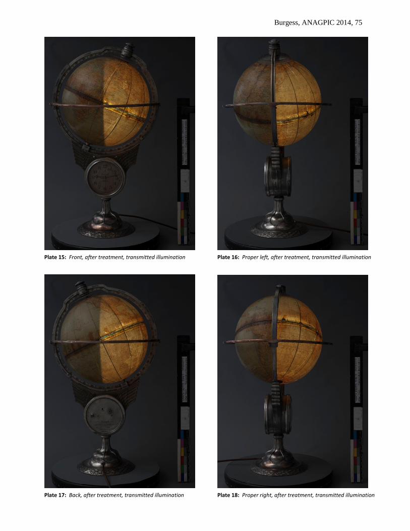
Burgess, ANAGPIC 2014, 75
Plate 15: Front, after treatment, transmitted illumination Plate 16: Proper left, after treatment, transmitted illumination
Plate 17: Back, after treatment, transmitted illumination Plate 18: Proper right, after treatment, transmitted illumination
Burgess, ANAGPIC 2014, 76
15. Appendices
15.1 Appendix 1: Fourier Transform Infrared Spectroscopy Settings
Attenuated Total Reflection (iTR ATR) FTIR Spectroscopy
Infrared spectra for samples of the calotte, light shade and globe materials were collected
using a Nicolet 6700 FTIR spectrometer (Thermo Scientific) with a Thermo Scientific Smart iTR
ATR accessory. Samples were analyzed by pressing them against the diamond ATR crystal.
Each spectrum collected was the average of 16 scans at 4 cm-1
spectral resolution. An ATR
correction routine was applied to compensate for variations in penetration depth with
wavenumber. Sample identification was primarily achieved by comparing ATR spectra of the
sample to spectral libraries of common conservation and artists’ materials (Infrared and Raman
Users Group, http://www.irug.org ) using Omnic 8.1.11 software (Thermo Scientific).
15.2 Appendix 2: Gas Chromatography - Mass Spectrometry Settings
A sample of the nitrocellulose globe was analyzed by Py-GC-MS. A Frontier Lab Py-2020D
double-shot pyrolyzer system was used for pyrolysis, and the pyrolysis interface was maintained
at 320 oC. The pyrolyzer was interfaced to an Agilent Technologies 7820A gas chromatograph
coupled to a 5975 mass spectrometer. An Agilent HP-5ms capillary column (30 m x 0.25 mm x
0.25µm) was used for the separation with He as the carrier gas set to 1 mL per minute. The split
injector was set to 320 oC with a split ratio of 50:1 and no solvent delay was used. The GC oven
temperature program was 40 oC for 2 minutes, ramped to 320
oC at 20
oC per minute, followed
by a 9 minute isothermal period. The MS transfer line was at 320 oC, the source at 230
oC, and
the MS quadropole at 150 oC. The mass spectrometer was scanned from 33-600 amu at a rate of
2.59 scans per second. The electron multiplier was set to the autotune value. Samples were
placed into a 50 µL stainless steel Eco-cup. An Eco-stick was fitted into the cup, and was placed
into the pyrolysis interface where it was purged with He for 3 minutes. Samples were pyrolyzed
using a single-shot method at 550 oC for 6 seconds. Sample identification was aided by
searching the NIST MS library.

Burgess, ANAGPIC 2014, 77
15.3 Appendix 3: X-ray Fluorescence Spectroscopy Settings
X-ray fluorescence spectra were collected using a Bruker Artax 400 energy dispersive X-ray
spectrometer system. The excitation source was a Rhodium (Rh) target X-ray tube with a 0.2
mm thick beryllium (Be) window, operated at 40 kV and 1000 μA current when detecting
heavier elements and 15 kV and 1200 μA current for lighter elements . The X-ray beam was
directed at the artifact through a collimator 1.0 mm in diameter. X-ray signals were detected
using Peltier cooled XFlash silicon drift detector (SDD) with a resolution of 146.4eV. Helium
purging was used to enhance sensitivity to light elements. Spectral interpretation was performed
using the Artax Control software. The spectra were collected over 90 seconds (live time).
15.4 Appendix 4: Spectral Power Distribution Curves for Replacement Light Sources
A spectrophotometer was used to test the appropriateness of two consumer-ready LED light
sources and two standard incandescent indicators to replace the burnt out incandescent bulb that
came with the Uniclok globe. In each case the bulb was screwed in to a night light holder,
plugged in to a 120V mains outlet, and angled such that it shone with maximum intensity at the
spectrophotometer set in to the head of the Oriel Micro-fading Tester. The output of each bulb
was captured by a Control Development Diode Array Spectrograph and interpreted and
presented as a spectral power distribution (SPD) curve using Spec 32 software (version 1.5.6.9).
The shape of each curve was used to determine the bulb’s suitability for the project.

Burgess, ANAGPIC 2014, 78
15.5 Appendix 5: Digital Recreations of the Time and Date Calottes
Burgess, ANAGPIC 2014, 79
15.6 Preventive Conservation Recommendations
The Uniclok globe is composed of a variety of materials, some of which degrade to produce
pollutants that can be deleterious to the object itself and other items in the museum collection.
The ideal storage scenario for the Uniclok object would involve good air exchange and/or the use
activated carbon pellets to reduce evolved acetic and nitric acid vapors. Activated carbon
impregnated with either potassium hydroxide or potassium carbonate has the best broad
spectrum absorption of acetic acid and nitrogen dioxide compared to other pollutant scavengers
like zeolites. Placing A-D Strips (developed by the Image Permanence Institute) in the vitrine or
storage box would provide a means of visually monitoring for the evolution of acidic vapors, as
could the use of sulphonephthalein indicators. Most importantly, the object should be segregated
to minimize the potential for its innate acidic vapors to harm other objects in the collection,
especially metals and other cellulose-based artworks.
Ideally the artwork should be kept in cool storage at approximately 45% relative humidity
(RH). This would slow the aging and decay of the plastic components and also the speed at
which the silver tarnishes. Care should be taken to not lower the RH below 40% where the paper
gores could start to experience mechanical damage due to an undesirable decrease in moisture
content.