Embed Size (px)
Citation preview

1
LAUNCH AND COMMISSIONING THE THE DEEP SPACE CLIMATE OBSERVATORY
Nicholas P. Frey*, Edward P. Davis†
The Deep Space Climate Observatory (DSCOVR), formerly known as Triana,
successfully launched on February 11th, 2015. To date, each of the five space-
craft attitude control system (ACS) modes have been operating as expected and
meeting all guidance, navigation, and control (GN&C) requirements, although
since launch, several anomalies were encountered. While unplanned, these
anomalies have proven to be invaluable in developing a deeper understanding of
the ACS, and drove the design of three alterations to the ACS task of the flight
software (FSW). An overview of the GN&C subsystem hardware, including re-
furbishment, and ACS architecture are introduced, followed by a chronological
discussion of key events, flight performance, as well as anomalies encountered
by the GN&C team.
INTRODUCTION
The Deep Space Climate Observatory (DSCOVR) successfully launched on February 11th,
2015 from the Cape Canaveral Air Force Station on a SpaceX Falcon 9 supplied by the United
States Air Force. The observatory was designed, built, and commissioned by the National Aero-
nautics and Space Administration (NASA) Goddard Space Flight Center (GSFC) in partnership
with the National Oceanic and Atmospheric Administration (NOAA). The spacecraft serves as
the replacement for the NASA GSFC Advanced Composition Explorer with the primary objective
of providing valuable science data pertaining to solar activity as well as early detection of any
extreme solar weather events via the observatory’s Plasma Magnetometer (PlasMag) instrument.
Additionally, the spacecraft contains two Earth-observing instruments, the Earth Polychromatic
Imaging Camera (EPIC) and the National Institute of Standards and Technology Advanced Radi-
ometer, which were developed to gather a range of measurements, from atmospheric and vegeta-
tion properties to changes in Earth's energy balance.
DSCOVR, formerly known as Triana, was originally conceived in the late 1990s as a NASA
Earth science mission that would provide a near continuous view of Earth and measure Earth's
albedo. Triana was developed under NASA’s Small Explorer (SMEX) program, but was canceled
and the satellite was placed into storage in 2001. In 2012, NASA brought the spacecraft out of
storage at NASA GSFC in Greenbelt, Maryland, where the spacecraft was originally built.
NOAA funded NASA to refurbish the spacecraft, recalibrate the space weather sensors, prepare
* Attitude Control Systems Engineering Branch, Code 591, NASA Goddard Space Flight Center, Greenbelt, MD. † Components and Hardware Systems Branch, Code 596, NASA Goddard Space Flight Center, Greenbelt, MD.
AAS 16-144
https://ntrs.nasa.gov/search.jsp?R=20160002428 2018-06-23T05:53:38+00:00Z

2
the spacecraft for launch, develop the ground systems and operations, and perform launch and
commissioning of the DSCOVR satellite.
In the first 36 hours after launch, the initial operations checkout phase included solar array de-
ployment, Sun acquisition, transition to Earth pointing, thruster polarity checks, an inertial refer-
ence unit calibration, and the first midcourse correction (MCC1). After its checkout, the space-
craft entered a cruise phase which included the deployment of the magnetometer boom, numerous
momentum unloading maneuvers, a set of PlasMag calibration slews, an additional midcourse
correction (MCC2), concluding with a 4 hour and 27 minute Lissajous orbit insertion (LOI) 115
days after launch. The observatory is currently stationed at the first Sun-Earth Lagrange point
operating nominally.
DSCOVR GN&C HARDWARE
The DSCOVR GN&C subsystem hardware consists of the following components: Four Inte-
grated Reaction Wheel Assemblies (IRWA) situated in a pyramidal configuration in the space-
craft bus. A Ball Aerospace and Technologies Corporation (BATC) CT-633 Star Tracker (ST)
mounted on top of the instrument deck. A Honeywell Block III Miniature Inertial Measurement
Unit (MIMU) mounted within the diagonal bus equipment bay along the -X and +Y axes. One
Adcole SMEX Digital Sun Sensor (DSS) mounted on the spacecraft’s Sun-facing side. Six Ad-
cole Coarse Sun Sensors (CSS) located on the corners of the Solar Arrays oriented such that there
are three sets of opposing pairs. A Utility Hub (UHUB) data interface and an engine valve driver
electronics box mounted within the spacecraft SMEX bus.
Figure 1. Diagram of DSCOVR GN&C Hardware.
The refurbishment of the DSCOVR observatory consisted of disassembly of the spacecraft
bus, evaluation of health and performance of each component, and as necessary, removal from
the spacecraft for reconditioning.

3
Integrated Reaction Wheel Assemblies
The IRWAs were designed and built by the GSFC Components and Hardware Branch (Code
596) and were developed as a single ‘off-the-shelf’ box for SMEX-Lite. Each IRWA has a maxi-
mum momentum of 11.4 Nms, and a full torque capacity of 8.4 Nm. The wheels are designed
with pressed in bearings, and as such, cannot be disassembled without damage. The only possible
flight spare wheel would have been an existing IRWA undergoing Life-testing in the Code 596
labs.
Starting in May of 2012, DSCOVR performed IRWA aliveness checks on the wheels, which
cycled each wheel to ± 190 rpm, verified that each appeared to be receiving commands, and re-
sponding nominally. These tests were followed by speed run-in tests to alleviate concerns of
bearing grease redistribution during the long storage. The wheels were spun to positive 2000 rpm
and held for 11 hours, followed by 11 hours of negative 2000 rpm to sufficiently redistribute
grease throughout each bearing.
The performance assessment test prior to de-integration of the IRWAs from the spacecraft was
a bearing noise test. Each wheel was spun to ± 500 rpm individually while an IRWA engineer
used a stethoscope to listen for noise in the bearings.
All four DSCOVR IRWAs were declared healthy prior to the instrument deck being separated
from the spacecraft. The IRWAs were then de-integrated from the spacecraft in order to have
magnetic shielding added to each IRWA enclosure to minimize the wheels’ magnetic signatures
impact on the PlasMag instrument. The wheels were re-integrated and went through the standard
spacecraft level testing regimes.
Miniature Inertial Measurement Unit
The Triana spacecraft originally contained a Honeywell Block I MIMU on-board. However,
the delivery of a similar unit for the Lunar Crater Observation and Sensing Satellite (LCROSS), a
co-payload with NASA’s Lunar Reconnaissance Orbiter (LRO), which launched in June of 2009,
was delayed due to a testing issue at the vendor. In order to make the LRO launch date, the
LCROSS project requested a swap for the Triana unit, which was approved. Triana’s original
MIMU impacted the moon in October of 2009. The Block III MIMU was sent back to Honey-
well for evaluation and refurbishment during the spring of 2013, where the gyro package within
the unit was replaced with updated technology to improve the expected lifetime of the MIMU.
The unit went through a full set of environmental and functional tests at Honeywell and returned
to GSFC. The Block III MIMU was integrated into the DSCOVR spacecraft bus in July of 2013.
Ball CT-633 Star Tracker
The BATC CT-633 ST was originally delivered to GSFC in March of 1999. The tracker was
shipped to BATC in Boulder, CO in September of 2012 for evaluation and testing of the unit.
This evaluation included the check of the on-board star catalog to verify that any updates to the
catalog since 1999 were insignificant to tracker performance. The tracker and star catalog were
proven to be fully functional, but the sun-shade’s original design was determined to violate the
sun exclusion angle requirement, which was initially defined for Triana. BATC re-worked, re-
coated and certified an engineering unit sun-shade and provided it to the DSCOVR mission. The
unit was returned to GSFC in May of 2013 and re-integrated to the spacecraft in June of 2013.
The tracker successfully went through all of the spacecraft environmental and systems testing
prior to launch.

4
Adcole Digital Sun Sensor
The Adcole DSS remained integrated to the spacecraft bus with the only electrical work done
being the connection of the instrument bus to the spacecraft bus when the spacecraft went through
its final re-integration. GN&C engineers performed DSS functional and coarse phasing tests on
the DSS. The coarse phasing tests were performed with a hand held lamp for stimulus at various
quadrants of the optical head, while observing the resultant commands to the IRWAs. This gave
only coarse phasing, and not full functional testing due to the limitations of the hand held lamp
stimulus. Issues with the DSS data processing post-launch are discussed later.
Adcole Coarse Sun Sensors
The CSSs remained integrated to the flight Solar Arrays and were then electrically re-
integrated to DSCOVR when the arrays were re-integrated. Functional and phasing tests were
performed by illuminating each CSS, and verifying in telemetry proper currents and polarities
from each pair of opposing eyes.
Utility Hub
The UHUB serves as a data conduit for GN&C components, which do not have the proper in-
terface to the spacecraft Command and Data Handling subsystem. It also holds an engine valve
driver card, which sends thruster firing command pulses to the propulsion subsystem. No re-
work was required to the UHUB and it was re-integrated to the DSCOVR spacecraft in
March/April of 2013. Full functionality of the UHUB was verified throughout spacecraft func-
tional testing.
DSCOVR ATTITUDE CONTROL SYSTEM
The DSCOVR ACS, is made up of five primary control modes; Science, Delta-V, Delta-H,
Sun Acquisition, and Safe Hold, defined in the following sub-sections. Figure 2 displays the
mode transition diagram, where the blue arrows represent nominal autonomous transitions, the
grey represent commanded transitions, and the red represent autonomous transitions via the Fail-
ure, Detection, and Handling framework.
Figure 2. DSCOVR Mode Transition Diagram.

5
Science Mode
Science mode is utilized for a majority of nominal operations. Applications include autono-
mous Earth-pointing, instrument calibration maneuvers, and inertial pointing to ground-specified
targets. Science mode lacks a Kalman filter and operates solely on knowledge from the ST and
MIMU.
Thruster Modes (Delta-V and Delta-H)
Delta-V and Delta-H are each executed approximately every three months for momentum un-
loading and station-keeping (each typically lasting 90 seconds or less). After completion of the
respective maneuver, the spacecraft autonomously re-enters the previous mode (nominally Sci-
ence mode).
Delta-H and Delta-V both incorporate the same position-derivative controller commanding
eight designated thrusters to control attitude while propagating on MIMU measurements through-
out the maneuver. Delta-H mode overrides the wheel torques to drive the wheels to a desired sys-
tem momentum. Delta-V commands a zero-torque override which causes the wheels to spin down
in the absence of drag compensation in addition to utilizing a pre-defined set of thrusters to adjust
the orbital velocity.
Sun-Pointing Modes
Sun Acquisition and Safe Hold each utilize either the CSSs or the DSS for attitude knowledge
while the reaction wheels are utilized for pointing control. Safe Hold is a gyroless control mode
and estimates body rates about the Sun-line using current and previous sun sensor measure-
ments as well as wheel tachometer information. Sun Acquisition utilizes the MIMU to pro-
vide rate information about the body axes. Both modes aim to orient the spacecraft so as to
maintain the spacecraft state within power and thermal constraints.
POST-LAUNCH TIMELINE AND FLIGHT ANOMOLIES
The following items outlined in Table 1 represent a selection of the activities throughout the
commissioning phase of DSCOVR. While incomprehensive, the activities discussed in this paper
aim to address the major ACS related anomalies the flight team faced, as well as noteworthy
events.
Table 1. Summary of Major Activities.
Activity Date (UTC) Duration
Post Separation 2015/042 – 23:42:45 N/A
MIMU Calibration 2015/043 – 11:00:00 3 hr, 20 min
MCC1 2015/044 – 07:00:00 37 sec
Boom Deployment 2015/046 – 15:50:00 1 min, 10 sec
Initial PlasMag Calibration 2015/069 –16:00:00 2 hr, 10 min
LOI 2015/158 – 17:00:00 4 hr, 27 min
EPIC Imaging 2015/160 – 14:00:00 Current

6
Post Separation
Shortly after separation from the Falcon 9, the spacecraft autonomously transitioned from Safe
Hold (with measurements obtained via the CSSs) to Sun Acquisition mode. Upon entering Sun
Acquisition mode, despite the DSS (the default sensor for Sun Acquisition mode) having sun
presence, FSW reported wild variances in computed sun vectors based on DSS measurements,
and was unable to take out pointing errors and achieve sun pointing attitude. The control system
began reporting an attitude error toggling between ± 30 degrees displayed in Figure 3. As this
behavior was detected, the decision was made to immediately issue a command to force the con-
trol system to ignore DSS measurements and utilize the CSSs while remaining in Sun Acquisition
mode. After transitioning to CSS measurements, the control error stabilized and this configuration
was preserved until transitioning to Science mode where the ST is the primary attitude sensor.
Figure 3. Post-Separation Controller Activity.
The anomalous readings from the DSS were traced to the DSS processing algorithm in the
ACS task of the FSW. The DSS output was being interpreted by the ACS as horizontal and verti-
cal angles, while the DSS was outputting Gray coded counts. An additional processing step was
subsequently added to the ACS FSW to perform a Gray to decimal conversion of DSS measure-
ments. Until the DSS processing algorithm was corrected on May 21st, 2015, the CSS force flag
was utilized to ensure the DSS signal was dismissed by the ACS.
Figure 4. Post-Separation Wheel Torque Commands.
As shown in Figure 4, the erroneous DSS measurements caused the control system to com-
mand wheel torques near control system saturated value of 0.16 Nm, which over a prolonged pe-
7
riod of time could have jeopardized the health and safety of the wheels. After forcing the use of
the CSSs, the erratic behavior dissolved and the spacecraft entered a steady state Sun-pointing
orientation.
MIMU Calibration
After the spacecraft reached steady state, a set of MIMU calibration slews were executed in
order to determine if any adjustments to the MIMU parameters were required before executing
MCC1, as the Delta-V mode propagates solely on rate measurements.
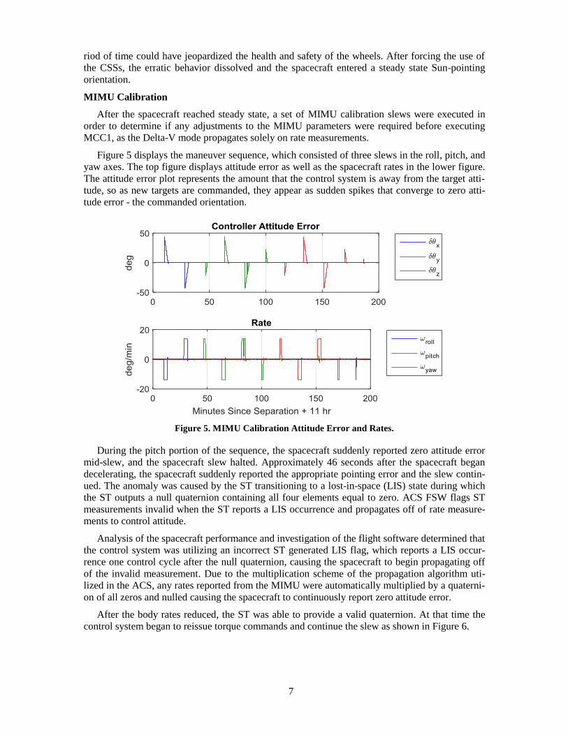
Figure 5 displays the maneuver sequence, which consisted of three slews in the roll, pitch, and
yaw axes. The top figure displays attitude error as well as the spacecraft rates in the lower figure.
The attitude error plot represents the amount that the control system is away from the target atti-
tude, so as new targets are commanded, they appear as sudden spikes that converge to zero atti-
tude error - the commanded orientation.
Figure 5. MIMU Calibration Attitude Error and Rates.
During the pitch portion of the sequence, the spacecraft suddenly reported zero attitude error
mid-slew, and the spacecraft slew halted. Approximately 46 seconds after the spacecraft began
decelerating, the spacecraft suddenly reported the appropriate pointing error and the slew contin-
ued. The anomaly was caused by the ST transitioning to a lost-in-space (LIS) state during which
the ST outputs a null quaternion containing all four elements equal to zero. ACS FSW flags ST
measurements invalid when the ST reports a LIS occurrence and propagates off of rate measure-
ments to control attitude.
Analysis of the spacecraft performance and investigation of the flight software determined that
the control system was utilizing an incorrect ST generated LIS flag, which reports a LIS occur-
rence one control cycle after the null quaternion, causing the spacecraft to begin propagating off
of the invalid measurement. Due to the multiplication scheme of the propagation algorithm uti-
lized in the ACS, any rates reported from the MIMU were automatically multiplied by a quaterni-
on of all zeros and nulled causing the spacecraft to continuously report zero attitude error.
After the body rates reduced, the ST was able to provide a valid quaternion. At that time the
control system began to reissue torque commands and continue the slew as shown in Figure 6.

8
Figure 6. MIMU Calibration Attitude Error and Rates.
The GN&C launch team determined that there was no threat to the health and safety of the
spacecraft. Mission operations concurred with the assessment and allowed the sequence to con-
tinue. Until a FSW patch was generated and implemented on May 21st, 2015, the mission adopted
a technique of disabling ST updates and propagation solely on MIMU measurements for the re-
mainder of the slews.
The First Midcourse Correction (MCC1)
Prior to launch, the MCC1 duration was expected to be on the order of several minutes, and
executed approximately 12 hours after launch. However, due to the high accuracy of the launch
vehicle, the coast period prior to the MCC1 was extended to 32 hours. Corrections to the MIMU
alignment and scale factors were originally considered to be optional prior to launch due to the
short duration of the Delta-V. However, while MCC1 was decreased, flight dynamists and mis-
sion managers opted to upload the adjustments to make use of the extended coast period. In addi-
tion to the planned thruster check out, a set of MIMU validation slews were performed prior to
MCC1 to ensure the parameters were applied correctly.
Approximately 32 hours after launch, the MCC1 was completed in 37 seconds (not including
time to slew to the target attitude and back), resulting in a total Delta-V of 0.49 m/sec.
Figure 7. MCC1 Attitude Offset.

9
Figure 7 displays the error in attitude throughout the burn, and it is shown that there is a dis-
tinct bias in the roll and pitch axes. This is caused by the offset of the center of mass and the
thrust vector (which in this case was along the +Z axis). This was a known bias prior to launch,
and a set of correction delta-quaternions were created in order to compensate for the offset in
pointing. Although, for MCC1, the corrections were left out of the burn plan to ensure the biases
were as the team expected and to avoid inadvertently adding the correction in the opposite direc-
tion. Throughout MCC1 the biases matched the predicted direction and magnitude, therefore the
corrections were implemented for both MCC2 and LOI. MCC2, which was executed 73 days af-
ter MCC1, has been omitted from the paper for conciseness, although the effects of implementing
the corrections are shown in the LOI section.
Magnetometer Boom Deployment
The 4-meter coiled boom telescopes outward in four intervals, completing one co-axial rota-
tion per interval. While the disturbance in attitude and rate were relatively unnoticed, Figure 8
displays the response of the wheels throughout the deployment.
Figure 8. Wheel Response to Magnetometer Deployment.
Based on the wheel response, as well as data provided by the magnetometer, the flight team
was able to conclude that all four of the magnetometer boom’s sections had successfully de-
ployed.
PlasMag Calibration Maneuver
To calibrate the PlasMag, the science team requested 10 revolutions at constant rate about the
spacecraft’s +X axis. However, the control system lacks rate commanding capability, and there-
fore the only way to obtain a smooth rate was to generate a series of ground commanded quater-
nions. The sequence was designed to command targets 90 degrees ahead in the counter-clockwise
direction, allowing the spacecraft to slew 30 degrees before issuing the following command (in-
formally referred to as the “dog chases tail” technique). This allowed the spacecraft to continually
follow targets without decreasing the body rates, as shown in Figure 9.

10
Figure 9. PlasMag Targeting with Resultant Rates.
Lissajous Orbit Insertion (LOI) Burn
Arguably the most critical event of the commissioning phase was the LOI. The maneuver was
split into two segments in order to optimize fuel usage by minimizing the opportunity for over-
burn. The first segment consisted of 90% of the total Delta-V followed by the remaining 10% to
complete the Delta-V as well as remove any residuals from the first segment.
While the LOI was of the same +Z Delta-V configuration as the previous two Delta-Vs
(MCC1 and MCC2), the burn durations were drastically different, as the two correction burns
lasted approximately 4 minutes combined.
Figure 10 displays a summary of the commissioning Delta-V maneuvers to provide a visual
representation of the maneuver timeline.
Figure 10. Transfer Trajectory Maneuvers Looking Down from North Ecliptic Pole.
As discussed in the MCC1 section, there existed attitude bias while performing a +Z Delta-V
as expected prior to launch and demonstrated in the first two mid-course corrections. Therefore,

11
by adjusting for this bias as shown in Figures 11 and 12, the roll and pitch errors were kept below
0.25 degrees, well within the Delta-V mode Level-3 pointing requirement of 5 deg. The error
along the thrust vector remained bounded by ± 1 deg, though this was of little concern as small
rotations about the thrust vector had little impact on the resulting Delta-V.
Figure 11. Attitude Error from First Segment of Lissajous Orbit Insertion Burn.
Figure 12 displays the attitude error for the second segment of the LOI and more clearly
shows the adjustments in target utilized to remove the bias.
Figure 12. Attitude Error from Second Segment of Lissajous Orbit Insertion Burn.
All pre-burn analysis was conducted utilizing the ACS High Fidelity Simulator created by the
DSCOVR ACS team. The errors in predicted to actual Delta-V duration was 0.89% for the first
segment, and 0.43% for the second segment. This accuracy was vital to the flight dynamics team,
as this provided better knowledge of how each of the thrusters onboard affected the resultant
change in spacecraft state.
Early EPIC Images
The EPIC door was opened on June 9th, 117 days after launch, and the first images were taken
on the same day. Over the course of the following three weeks, images were collected in order to
determine the offset of Earth in the field of view of EPIC. Over the initial imaging period, the
estimated offset was 0.06 deg in pitch, and 0.04 deg in yaw.
12
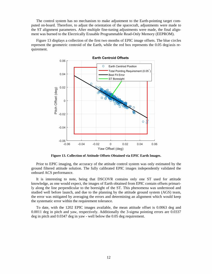
The control system has no mechanism to make adjustment to the Earth-pointing target com-
puted on-board. Therefore, to adjust the orientation of the spacecraft, adjustments were made to
the ST alignment parameters. After multiple fine-tuning adjustments were made, the final align-
ment was burned to the Electrically Erasable Programmable Read-Only Memory (EEPROM).
Figure 13 displays a collection of the first two months of EPIC image offsets. The blue circles
represent the geometric centroid of the Earth, while the red box represents the 0.05 deg/axis re-
quirement.
Figure 13. Collection of Attitude Offsets Obtained via EPIC Earth Images.
Prior to EPIC imaging, the accuracy of the attitude control system was only estimated by the
ground filtered attitude solution. The fully calibrated EPIC images independently validated the
onboard ACS performance.
It is interesting to note, being that DSCOVR contains only one ST used for attitude
knowledge, as one would expect, the images of Earth obtained from EPIC contain offsets primari-
ly along the line perpendicular to the boresight of the ST. This phenomena was understood and
studied well before launch, and due to the planning by the attitude ground system (AGS) team,
the error was mitigated by averaging the errors and determining an alignment which would keep
the systematic error within the requirement tolerance.
To date, with the 1202 EPIC images available, the mean attitude offset is 0.0063 deg and
0.0011 deg in pitch and yaw, respectively. Additionally the 3-sigma pointing errors are 0.0337
deg in pitch and 0.0347 deg in yaw - well below the 0.05 deg requirement.

13
CONCLUSION
All of the anomalies in this paper were resolved and all FSW and parameter changes have
been burned to EEPROM. On September 29, 2015 the DSCOVR team successfully completed the
Post Launch Acceptance Review, and handed over to NOAA on October 28, 2015.
DSCOVR publically released the first EPIC images on June 13, 2015 and has since performed
nominally, continuing to provide daily images of the sun-lit face of the Earth.
ACKNOWLEDGMENTS
The authors would like to thank the DSCOVR ACS analysis team; Joseph Garrick, Huaizu
You, and Michael Nemesure; the GN&C hardware engineers Linh Nguyen and Eric Rogstad, as
well as the AGS team; Philip Calhoun, Rick Coon, Jonathan Glickman, and David Hooshmand.
In addition, the ACS FSW engineer, Bruce Trout, and the Mission Systems Engineer, Gary
Meadows, provided invaluable assistance pre-launch and throughout the commissioning phase.