Embed Size (px)
Citation preview
m Volume 66, 1991
AATCC TECHNICAL MANUAL
c
AMERICAN ASSOCIATION OF TEXTILE CHEMISTS AND COLORISTS P. 0. Box 12215, Research Triangle Park, N. C. 27709, USA
Tel: 919/549-8141; Fax: 919/549-8933

AATCC Test Method 20-1990
Fiber Analysis: Qualitative Develo ed b AATCC Committee RA24. l d o tedYas Tentative 1955; re- vised 1 9 5 l 1962, 1963, 1972, 1976; editorially revised and reaffirmed 1973, 1990; editorially revised 1974, 1977, 1982 (new title), 1983, 1984, 1988; reaffirmed 1985.
1. Purpose and Scope
1.1 This test method describes physi- cal, chemical and microscopical tech- niques for identifying textile fibers used commercially in the United States. Fibers may be examined in raw fiber form or taken from yarn or fabric.
1.2 These test methods may be used to identify generic fiber types as defined by the Textile Fibers Products Identification Act and subsequent rules and regulations of the Federal Trade Commission. Quan- titative methods for determining per- centages in blends of fibers are covered by AATCC Test Method 20A, Fiber Analysis: Quantitative.
1.3 The test methods apply to fibers which are shown below grouped by ) generic classifications:
Natural Fibers Man-Made Fibers Cellulose (Vegetable) cotton flax hemp jute ramie sisal (agave) manilla hemp (abaca)
Keratln (Animal) alpaca camel cashmere horse llama mohair rabbit silk
vicuna wool
Bombyx (cultivated) tussah (wild)
Mineral asbestos
acetate
acrylic anidex aramid azlon glass metallic modacrylic novoloid nylon
6
nytril olefin
polyethylene polypropylene
polyester rayon
cuprammonium viscose
rubber saran spandex vinal vinyon
secondary triacetate
6-6
2. Use and limitations
2.1 This test method describes a num- ) ber of procedures-microscopical exam- ination, solubility in solvents, melting point, refractive index, etc.-which should be used in combination to identify a fiber type. For identifying certain fibers
some procedures will be found to be more effective than others.
2.2 For example, microscopical exam- ination is particularly useful in charac- terizing the natural fibers. It must be used with caution on manmade fibers since they are frequently produced in a number of modifications which alter the longi- tudinal or cross-sectional appearance. In addition, man-made fibers may contain some or no delusterant or other additive particles. Filaments of a given type may vary in size or cross-sectional shape. Individual filaments may have two or more component sections of the same or different generic types.
2.3 Even natural fibers show a fairly wide variation in typical cross-section. No specific specimen will look exactly like the pictures published. A sufficient number of fibers should be examined to cover the range of appearance in any specimen.
2.4 Successful identification of fibers depends upon experience and familiarity with the fibers. The identification of an unknown fiber is best made by compar- ison with properly identified fibers used as reference standards. For this reason it is desirable to have available at least one representative fiber sample from each generic class of fibers, which can be used for comparative identification.
2.5 This test method provides means for identifying the generic classification of the common fiber types. In special cases, as when dealing with fibers not described in this method or attempting to distinguish between products of different suppliers of the same generic types, one must consult standard texts on fiber iden- tification or technical bulletins issued by suppliers of man-made fibers. See ref- erences Section 13.
3. Terminology
3.1 Key terms in this test method have not as yet been determined. Definitions will be added when agreed upon.
4. Safety Precautions
NOTE: These safety precautions are fqr information purposes only. The pre- cautions are ancillary to the testing pro- cedures and are not intended to be all inclusive. It is the user’s responsibility to use safe and proper techniques in han- dling materials in this test method. Man- ufacturers MUST be consulted for spe- cific details such as material safety data sheets and other manufacturer’s recom-
mendations. All OSHA standards and rules must also be consulted and fol- lowed.
4.1 Good laboratory practices should be followed. Wear safety glasses in all laboratory areas.
4.2 All chemicals should be handled with care.
4.3 In preparing, dispensing and han- dling the reagents outlined in Section 6, use chemical goggles or face shield, impervious gloves and an impervious apron. Concentrated acids should be han- dled only in an adequately ventilated lab- oratory hood. CAUTION Always add acid to water.
4.4 All poisonous and flammable reagents should be mixed and handled only in an adequately ventilated labora- tory hood. CAUTION Acetone and ethyl alcohol are highly flammable and should be stored in the laboratory only in small containers away from heat, open flame and sparks.
4.5 An eyewash/safety shower should be located nearby and an organic vapor respirator should be readily available for emergency use.
4.6 Exposure to chemicals used in this procedure must be controlled at or below levels set by governmental authorities (e.g., Occupational Safety and Health Administration’s [OSHA] permissible ex- posure limits [PEL] as found in 29 CFR 1910.1000 of January 1, 1989). In addi- tion, the American Conference of Govem- mental Industrial Hygienists (ACGIH) Threshold Limit Values (TLVs) comprised of time weighted averages (TLV-TWA), short term exposure limits (TLV-STEL) and ceiling limits (TLV-C) are recom- mended as a general guide for air con- taminant exposure which should be met (see 12.5).
5. Apparatus
5.1 Compound microscope with matched objectives and eye pieces to achieve magnifications of 100-500 X and equipped with a polarizer and analyzer.
5.2 Glass slides and cover glasses. 5.3 Dissection needles. 5.4 Scissors (small) and tweezers
(fine). 5.5 Cross-sectioning device of one
type such as listed below. 5.5.1 Stainless steel plate, 2.54 x 7.62 x
.0254 cm (1 x 3 x 0.01 in.) drilled with .09 cm (0.04 in.) diameter holes. Soft copper magnet wire AWG #34, .016 cm (0.0063 in.) diameter.
5.5.2 Microtome, hand (see
AATCC Technical Manuail1991 47

12.1). 5.6 Razor blades, sharp, thin, single
edge or double edge with holder. 5.7 Density gradient tube, glass
approximately 2.5 cm (1 in.) in diameter and 45 cm (18 in.) long with a sealed bottom and a 24/40 standard taper joint glass cap closure at top to avoid moisture pickup or evaporation of solvents. Tiny glass spheres of calibrated density may be used as density standards (see 12.2).
5.8 Melting point apparatus consisting of a heated block, temperature measuring device such as a thermometer, and means for controlling the rate of heating and viewing the specimen at low magnifica- tion. The instrument should have a range of 100-3OOC or more, and an accuracy of f 1 degree over the entire range (see 12.3).
6. Reagents and Materials 6.1 Mounting Reagents. 6.1.1 Mineral oil, U.S.P. or other
immersion fluid (see 12.4). 6.1.2 Collodion, solution of nitrocel-
lulose (4 g/100 mL) in 1:3 alcohol/ethyl ether.
6.2 Bleaching Reagent. 6.2.1 Hydrosulfite-caustic solution.
Dissolve 2 g sodium hydrosulfite and 2 g sodium hydroxide in 100 mL of water.
6.3 Staining Reagents. 6.3.1 Zinc chloro-iodide reagent. Dis-
solve 20 g of zinc chloride in 10 mL of water. Add 2.1 g of potassium iodide and 0.1 g of iodine dissolved in 5 mL of water. Add a leaf of iodine.
6.3.2 Acid phloroglucinol reagent. Dissolve 2g of phloroglucinol in lOOmL of water. Use with equal volume of con- centrated hydrochloric acid.
6.4 Refractive Index Immersion Liq- uids
6.4.1 Hexadecane (cetane) C. P. Grade, R1 = 1.434.
6.4.2 Alpha chloronaphthalene, RI = 1.633. Poisonous. Avoid inhaling vapors.
6.4.3 Blends of the above. Assume that the refractive index varies linearly by volume of ingredients. For example, to make a liquid of RI = 1.550 mix 42 parts by volume of hexadecane with 58 parts by volume of alpha chloronaphtha- lene (see 12.4).
6.5 Fiber Solvents. 6.5.1 Acetic acid, glacial. Corrosive.
Do not get in eyes or on skin. 6.5.2 Acetone, reagent grade. (Cau-
tion: highly flammable). 6.5.3 Sodium hypochlorite Folution,
5%. Home laundry bleach is 'satisfac- tory.
6.5.4 Hydrochloric acid, concentrated reagent, 20%. Dilute 50 mL of concen- trated hydrochloric acid, 38%, to 95mL with distilled water.
6.5.5 Formic acid, 85%. Corrosive.
Do not get in eyes or on skin. 6.5.6 1,Q-Dioxane. 6.5.7 m-Xylene. 6.5.8 Cyclohexanone. 6.5.9 Dimethylformamide. (Caution:
if spilled on skin, wash off immediately.) 6.5.10 Sulfuric acid solution, 59.5 f
0.25% by weight, density 1.4929 2 0.0027 g per mL at 20C. Weigh into a beaker 59.5 g of concentrated sulfuric acid (sp gr 1.84). Weigh into a 250mL Pyrex Erlenmeyer flask 40.5 g of distilled water. Cautiously add the acid to the water swirling and cooling in ice water or under a tap, Wear goggles! The solu- tion becomes very hot and may boil and spatter if not cooled during mixing. After the solution has cooled to 20C (68F) adjust the density to a value between 1.4902 and 1.4956 g per mL.
6.5.11 Sulfuric acid solution, (70 2 1% by weight, density 1.6105 -C 0.01 16 g per mL at 20C). Weigh 70 g of con- centrated sulfuric acid (sp gr 1.84) and 30 g of water and mix with the same precautions as in Section 6.5.10. After the solution has cooled to 20C (68F) adjust the density to a value between 1.5989 and 1.6221 g per mL.
6.5.12 m-Cresol, reagent grade. Poi- sonous. Use in ventilated hood.
6.5.13 Hydrofluoric acid, 49% reagent grade. Very dangerous. Use gog- gles and hood under suction. Do not inhale vapors or allow to contact skin.
7. Sampling 7.1 To obtain a representative sample
for identification it is necessary to con- sider the following:
7.1.1 If the sample is loose fiber or yarn, it may contain one fiber only or it may be an intimate blend of two or more fibers.
7.1.2 A yarn sample may be a ply or wrapped core blend of two or more yarns. These yarns in turn may be the same or different and may themselves contain a blend of fibers.
7.1.3 Woven and knitted fabrics may be constructed of the same or different yarns in various combinations. The yarn may contain one or more fiber types.
7.1.4 Different fiber types may be dyed to the same color. Contrarywise, the same fiber type may appear in dif- ferent colors in the finished article by mixing stock dyed or yarn dyed materials or using fibers with modified dyeing characteristics.
7.1.5 It is essential that the specimens selected represent the entire sample of raw fiber, yarn or fabric under exami- nation.
8. Specimen Preparation 8.1 In many cases the identity of an
unknown fiber can be established without
pretreatment. 8.2 When the presence of starch, wax,
oil or other coating obscures the appear- ance of the fiber, try heating in warm to hot distilled water to remove the foreign matter. If this fails, try extracting with organic solvents, 0.5% hydrochloric acid or 0.5% sodium hydroxide. Some fibers such as nylon are damaged by acid and some such as azlon, silk and wool, are damaged by caustic treatment (see Section 9.7).
8.3 To separate vegetable fiber bun- dles, treat with 0.5% sodium hydroxide solution, rinse well with water and dry.
8.4 To strip dye from colored fibers, especially the cellulosic fibers, heat for 30 minutes at 50C with hydrosulfite caus- tic solution (see 6.2.1).
9. Procedure 9.1 The identification of fibers is usu-
ally carried out by subjecting specimens to a variety of selected tests until enough information is obtained to make a satis- factory judgment as to the generic class or specific type. The selection of tests and order in which they are performed can change depending on the knowledge already available and results of the pre- liminary tests.
9.2 Visual and Microscopical Exami- nation.
9.2.1 Examine the sample of material submitted for identification. Note form (loose fibers, yarn, fabric, etc.), color, fiber length and fineness, uniformity of appearance and probable end-use. If the sample is a fabric, separate out yarns by unraveling or cutting. if the fabric is woven, separate warp and filling yams. If yarns differ in color, luster, size or other apparent ways, make a physical separation of these yarns for separate identification.
9.2.2 Place a small quantity of the fibers on a glass slide. Tease fibers apart, mount with a drop of mineral oil or other immersion fluid, cover with a glass cover slip and examine at 100 X under the microscope using transmitted light.
9.2.3 Observe the fiber characteristics as seen in traverse section and classify into four general classes.
9.2.4 Fibers with surface scales. These are the animal hair fibers listed in Purpose and Scope (Section 1.3). All of the ker- atin fibers listed except silk are included in this group. Continue detailed micro- scopical examination including cross- section examination (Section 9.3). Com- pare with the characteristics in Table I, photographs in the appendix of this method, and known specimens of hair fibers. Additional confirmation of this class may be made by burning test (Sec- tion 9.5); density (Section 9.6); and sol- ubility (Section 9.7).
9.2.5 Fibers with Cross Markings.
48 AATCC Technical Manual/l991

t
3
I
These are the vegetable fibers other than cotton listed in Section 1.3. Continue detailed microscopical examination including cross-section examination (Section 9.3). Compare with character- istics as given in Table 11, photographs and known specimens of vegetable fibers. To distinguish flax and ramie from hemp, observe the direction of rotation on drying (Section 9.8). If the fibers are light in color, stain with zinc chloro- iodide reagent and with acid phloroglu- cinol as directed in Section 9.9. Addi- tional confirmation of this class may be made by tests described in Sections 9.4, 9.5, 9.6 and 9.7.
9.2.6 Twisted fibers. This class includes cotton and tussah silk. The two are easily distinguished by cross-section (Section 9.2), burning test (Section 9.5) and solubility (Section 9.7). If fibers are light in color, they may be distinguished by staining with zinc chloro-iodide reagent (Section 9.9).
9.2.7 Other Fibers. This class includes all of the man-made fibers, Bombyx silk and asbestos. The latter two can be iden- tified by microscopical appearance including cross-section (Section 9.3). Buming tests (Section 9.5) and solubility tests (Section 9.7) are especially signif- icant for asbestos and are useful in con- firming the presence of silk.
The man-made fibers are best identi- fied by solubility, melting point, refrac- tive indices and other optical character- istics and density: properties which relate to chemical nature rather than physical shape. Cross-sections may vary and staining tests can be misleading since modifications of a generic type may dye differently. Used with discrimination and in combination with other tests, cross- sections and dye tests may sometimes be helpful in narrowing down the number of possibilities. Metallic fibers have a dis- tinctive shiny appearance which makes them easy to identify as a class.
9.3 Microscopical Cross-section Examination.
9.3.1 Obtain a parallel bundle of fibers or yarn. Thread a loop of copper wire through one hole in the stainless steel plate. Catch the bundle or yarn in the loop and pull it through the hole. Use suffi- cient fibers to pack the hole full. If nec- essary, use some extra, readily identifi- able other fiber to fill up the hole.
9.3.2 With a sharp razor blade make a smooth cut on both sides of the plate.
9.3.3 Examine the section in air, or covered by a mounting fluid like mineral oil under a cover slip. Use transmitted light and useful magnification of 200-500 X. Compare with photographs in Appen- dix or cross-sections of known fibers.
9.3.4 If the Hardy type microtome is used, follow instructions with the instru- ment. Insert a bundle of fibers or yarn into the slot. Slide the tongue into the
Table I-Characteristics of Fibers with Schles on Surface Note: The characteristic designated by a capital letter,)( in this table is that which is
especially significant. f
Microscopical Cash- Appearance Alpaca Camel mere Horse Llama Mohair Vicuna Woolc Longitudinal:
Epidermis: X Pronounced - x - - - -
Faint X X X X X X Coronal" - X X x - - Im bricateb X X Smooth edge - Serrated edge x - - X x - - - Occurrence:
Usually present x - - X x - - - Seldom present - X Never present - - x - - - - - Fragmental X X Interrupted X Continuous X
- - X X
X X X X X X X
- X X - - - Med uI la:
X X X - - - Type:
X X X X X X X
X X X
- - - - - - - - - - Size (ratio to fiber
diameter): X X X
X
- - - - - Under Y' Vl to Y2 X Over V2 - - - x - - - -
Diffuse - - - - - - Streaky X X X Granular - - - - -
- x - X None Cross-Section :
Contour:
- X X X - -
Pigment: - X - X - X - X - X - - - -
X X X X X X X X
X
- Round to oval - Oval to elongated x - - - - - Kidney X
Round to oval - - - Oval to elongated X - - - x - - - Kidney to
dumbbell x - - - x - - -
- - - - - - Medulla contour:
X X X - X
Pigment distribution: - X - X Uniform X x - - Centric - - x - - - - Eccentric - - - x - - - -
Average 26to28 18 15to16 - 26to28 - 13to14 - Fineness (in pm)
Range lo t050 9t040 5to30 - 10to40 lot090 6to25 lOto70 - 6t07 - - Under - Over
per 100 pm 5.5 5.5 Number of scales -
Coronal means crownlike, and refers to scales in which the visible scale edge completely encir-
* Imbricate means overlapping, and refers to scales in which the visible scalt, edges overlap like cles the fiber.
shingles on a roof and cover only a part of the fiber circumference. The term wool is used here to represent clothing wool and not carpet wool.
Table Il-Appearance of Fibers with Cross Markings or Swellings Longitudinal Section: Flax Hemp Ramie Ratio, lumen of fiber diameter under Y3 usually over % over Y3
Cell ends pointed blunt or forked blunt Cross-Section: Contour sharp rounded elongated
Lumen round or irregular polygon polygon polygon
irregular oval
slot to compress the bundle. Adjust the quantity of fibers for a tight package. Cut off both sides. Apply a drop of collodion to one cut face, wait until it shows through on the other side and then apply a drop to the other side. Let dry thor- oughly. Slice off excess collodion and
fiber on both sides of the plate with a sharp razor blade.
9.3.5 Attach the auxiliary plunger, and with the screw advance the embedded tuft through the slot until it protrudes 20- 40 p,m above the plate. Add a drop of collodion and let dry about 5 minutes or
AATCC Technical Manual/l991 49

until firm. Slice off collodion and embed- ded fiber section with a sharp razor blade held at about 45 degree angle with the slot. Cut with a single stroke.
9.3.6 Remove the section, transfer to a glass slide, mount with a drop of min- eral oil or other immersion liquid, add a cover slip and examine. Continue to cut sections as described in Section 9.3.5 until good clear cross-sections are obtained. Examine and compare to known cross-sections.
9.4 Refractive Index 9.4.1 Place a small sample of the fiber
on a glass slide. Immerse in a drop of a- chloronaphthalene and cetane mixture (or equivalent) of refractive index 1.55.
9.4.2 Insert the polarizer into the sub- stage of the microscope to provide light polarized in the 6-12 o'clock direction. Align the long dimension of a fiber in the same direction. Close the diaphragm of the substage condenser so as to provide axial illumination.
9.4.3 Focus carefully on the outlines of the fiber. With the fine adjustment, raise the focus to just above the top of the fiber. If the fiber is roughly a cylinder, it will act like a lens. If the refractive index of the fiber is higher than the immersion liquid, the fiber will act like a positive lens. A bright line of light will move into the middle of the fiber as the focus is raised. If the refractive index of the fiber is lower than the immersion liq- uid, the light will flare out as the focus is raised and the middle of the fiber will become darker. Repeat until certain of the direction.
9.4.4 The test can be seen best with round fibers. On flat ribbons it may be easier to see movement of a bright line- the Becke line-at the outlines of the fiber. Movement is in the same direction, toward the medium of higher refractive index as the focus is raised.
9.4.5 Rotate the specimen 90 degrees and repeat the test.
9.4.6 Rotate the specimen 45 degrees. Insert the analyzer in the body tube or eyepiece to provide crossed polars. Observe if the fiber appears very bright (strong birefringence), dim (weak bire- fringence) or dark (no birefringence).
9.4.7 Refer to Table IV for refractive index of fibers in the long and cross direc- tion and an estimate of birefringence. Consider that the retardation depends on the thickness of the fiber specimen as well as the extent of drawing of a given specimen. Compare with known fibers of similar diameter for birefringence.
9.4.8 Select other immersion liquids and repeat Sections 9.4.1 through 9.4.5. As the refractive index of the liquid approaches that of the fiber, the outlines of the fiber become less distinct. Match the liquid to the fiber within 0.01 refrac- tive index.
9.5 Burning Test.
Table Ill-Reaction to Flame
Melts Shrinks Burns Continues Near From in to Flame Flame Flame Burn
Natural Fibers silk Yes Yes Yes slowly woo1 Yes Yes Yes slowly cellulose no no yes Yes asbestos no no no no
Appearance of
Ash
soft black bead irregular black light greyish may blacken
Man-Made Fibers acrylic acetate azlon nytril polyester
nylon
olefin vinal modacrylic saran vinyon metallic glass
rubber spandex
anidex
rayon aramid
novoloid
hard black irregular shaped
bead hard black round bead hard grey
round bead hard tan bead
hard black irregular bead
metal bead hard clear
bead irregular mass
fluffy black or grey
brittle black irregular bead
none hard black
bead carbon
no
no Yes
no
Table IV-Physical Properties of fibers
Density Melting glcc Point
Degree C Refractive Index Birefringence
Natural Fibers asbestos (chrysotile)) cellulose silk wool and other hair
Man-Made Fibers acetate, secondary acetate, tri. acrylic anidex
aramid
azlon glass metallic modacrylic
novoloid nylon nylon 6-6 nytril polyester
polyethylene polypropylene rayon rubber saran spandex vinal vinyon
Long Cross
1.50-1.55 1.58-1.60
1.55-1.56 1.59
1.49 strong 1.52-1.53 strong 1.54 strong 1.55 weak
2.1-2.8 over 350 1.51 none 1.32-1.34 none 1.1 5-1.30 none
1.47-1.48 1.47-1.48 1.50-1.52
opaque
- 1.53-1.54 1.55
1.47-1.48 weak 1.47-1.48 weak 1.50-1.52 weak, negative -
1.32 260 1.30 288 1.12-1.19 none
softens 1.22 at 190
1.38 chars at 400
1.30 none 2.4-2.6 850
strong - 1.53-1.54 none 1.55 none
1.53 weak - opaque
1.54 varies over 300 1.30 or 188'or 1.36 120 1.25 none 1.12-1.15 213-225 1.12-1.15 256-265 1.20 21 8 1.38 or 250-260 1.23 or 282 0.90-0.92 135
1.5-1.7 1.57 1.51 1.58 1.52 1.48 1.48
or 1.63 1.71-1.73 1.53-1.54
none strong strong nil intense
strong strong strong
weak, negative 3_
~.
1.56 1.51 1.56 1.51 1.54-1.56 1.51-1.53
0.90-0.92 170 1.51 none 0.96-1.06 none 1.70 168
1.34-1.37 230 or
1.20-1.21 230 1.26-1.30 -
400
opaque 1.61 1.61
opaque 1.55 1.52 1.53-1.54 1.53
strong weak, negative
Not sharp. Sticking point is 176C.
50 AATCC Technical Manuall1991

Table V-Solubility of Fibers
a, E 0 0
0 3
a, C a, ._
0 2
a, .y .= &
3 -5 z ti (u x
9 C $ 2
" m 22 E m 2 c-
0 m 0 L .- P)
0
2 C E $5 .$ .,o 3:: 2 .o 5 ss - g g 25 22 %$ Y ? $ 2: 2:
5 8 4 5:
Concentration (YO) 100 100 5 20 85 100 100 100 100 59.5 70 100 50 Temperature (C) 20 20 20 20 20 101 139 156 90 20 38 139 20 Time (minutes) 5 5 20 10 5 5 5 5 10 20 20 5 20
acetate acrylic anidex aramid azlon cotton & flax glass modacrylic novoloid nylon nytril olefin polyester rayon saran silk spandex teflon vinal vinyon wool
s s I I I I I I I I I I I I s I I I I I I I SE I I I I I I I I I I I I I I I I I I I I I I I 1 S I I I I I I
I s I I I s
I S
s s I s I I I I
I I I I I I I I I SP I s I I I I s I I I I I I s I I s s I I I I I I I I I s s s I I I I I I I I
S s s s s I I P I
I I I I I I I I I
I I S I I
s I I SP I I I I I I I s I I s s I I S I I I I S S I s SP SP SP I I I I I I I I I
I I I I ~~
S =Soluble I =Insoluble cross-section. P = Forms plastic mass N = Nylon 6 in soluble, nylon 6/6 is insoluble. SP =Soluble or forms plastic mass
SE = Soluble except for one modacrylic fiber characterized
*
t = Novoloid turns red. =Soluble at 20 C without plastic mass.
9.5.1 Take a small tuft of fibers (held acrylic, nylon and spandex-have char- in tweezers) and place close to the side acteristic odors which can be recognized of a small flame. Note if the fibers melt with experience. or shrink from the flame. 9.6 Density.
9.5.2 Move the fibers into the flame. 9.6.1 Prepare a density gradient col- Note whether the fibers will bum when umn as follows. Clamp the density gra- held in the flame. Remove from the flame dient glass tube in a firm vertical stand. very slowly and carefully. Note whether Pour into the tube 25 mL of tetrachlo- the fibers continue to bum outside of the roethylene. Now prepare mixtures of flame. Make sure that the fiber was xylene and tetrachloroethylene by vol- ignited before making this latter obser- ume in descending order of percent tetra- vation. chloroethylene: 90/10, 80/20, 70/30,
9.5.3 Blow out the flame, if still burn- 60/40, 50/50, 40/60, 30/70, 20/80 and ing, and smell the smoke. Note the odor 10/90. Pour 25 mL of each in order care- and examine the color and nature of any fully down the side of the gradient tube. ash residue. Finally, put 25 mL of xylene on top.
9.5.4 Compare the behavior observed 9.6.2 Take short fragments of dyed with that listed in Table III and that of reference fibers and tie in a knot snipping known reference fibers. Flame retardant off loose ends. Boil for about two min- modifications of some fibers-cotton, utes in xylene solvent to remove moisture rayon, acetate and modacrylic, for exam- and air. Place in the column. After about ple-are available. Burning is retarded; a half hour they should come to rest at odor on burning and ash may be changed. the level representing their density. Cal- Colored fibers-especially those colored ibrated glass spheres may be used to by pigments-will retain color in the col- determine the actual density at various ored residue. levels.
9.5.5 Odors of some burning fibers are 9.6.3 Prepare the unknown fiber in like quite characteristic. The animal fibers manner, place in the gradient column and and man-made protein fibers (azlon) have note at what level it floats. Densities of the odor of burning hair or feathers. The fibers are listed in Table IV. vegetable fibers and regenerated cellu- lose (rayon) smell like burning paper. The smell of burning rubber is a familiar odor. Other manmade fibers-such as
.>
3 9.7 Solubility Test. 9.7.1 For tests at room temperature
(20C) place a small sample of the fibers in a watch crystal, test tube or 50 mL
AATCC Technical Manual/l991
by low flammability and liquid inclusions visible in
beaker and cover with the test solvent, Table V. Use about 1 mL of solvent per 10 mg of fiber.
9.7.2 If the test is conducted at the boiling point of the solvent, first bring the solvent to a boil in a beaker on an electric hot plate in a ventilated hood. Adjust the hot plate temperature to main- tain slow boiling and keep watch so that the solvent does not boil dry. Drop fiber sample into the boiling solvent.
9.7.3 If the test is conducted at some intermediate temperature, heat a beaker of water on a hot plate and adjust the temperature with a thermometer. Place the fiber sample in the test solvent in a test tube and immerse in the heated water bath.
9.7.4 Note if the fiber dissolves com- pletely, softens to a plastic mass or remains insoluble. Compare with data on fiber solubility in Table V.
9.8 Drying Twist Test. 9.8.1 Separate out a few parallel
fibers. Dip in water and squeeze off excess. Tap the end of the bundle to make separate fibers flare out. Hold over a hot plate in warm air to dry the fibers. Hold the fibers so that the free ends point toward the observer. Note the direction of twist as the fibers dry. Flax and ramie twist in a clockwise direction; hemp and jute twist in a counter clockwise direc- tion.
51

9.9.1 Place a few fibers on a micros- copical slide. Apply a drop of zinc chloro-iodide reagent and cover with a cover slip taking care to avoid bubbles. Examine the fibers for staining. Hemp, ramie and cotton stain violet; flax stains brownish violet; jute stains brown. Many other fibers stain shades of yellow brown including silk.
9.9.2 Warm a few fresh fibers on a microscopical slide with a drop of acid phlorogucinol reagent. Woody fibers such as unbleached jute stain a deep magenta because of the presence of lig- nin.
9.10 Melting Point. 9.10.1 Fisher-Johns Apparatus 9.10.2 Place a few fibers on the clean
heating block. Cover with a cover slip.
dial on 90 for fast heating. Observe the thermometer and the sample. When the temperature reaches IOOC, reduce the rate of heating. (If previous tests already indicate the fiber, the rate can be set at about 10 degrees per minute until 10-20 degrees below the expected melting
should be reduced to about 2 degrees per minute.
9.10.3 Observe the fibers for evidence of softening. At the melting point, liquid begins to form which wets the cover slip. Fibers eventually merge and form a liq- uid mass. As the test is in progress it is sometimes helpful to press gently on the cover slip with tweezers to see if the fibers flatten under pressure. If this melt- ing point is passed at a high heating rate, repeat the test with a fresh sample.
9.10.4 Compare the melting point found with those listed in table IV.
9.10.5 Kofler Hot Stage. 9.10.6 Place a few fibers on one of the
small glass slides provided and cover with a cover slip. Place the slide on the stage of the microscope with the fibers over the central hole of the stage. Put the baffle and cover plate in place.
9.10.7 Insert the polarizing accesso-
I Turn the heat on and set the heating rate
I point.) Near the melting point the rate
ries in the optical path of the microscope to provide crossed polars. The fibers should be visible if aligned diagonally to the direction of polarization. If fibers are not visible under these lighting condi- tions, remove the polarizing accessories and observe in ordinary transmitted light.
9.10.8 Set a high heating rate with the voltage regulator until the temperature reaches IOOC. Reduce the rate as the expected melting point is approached as directed in Section 9.10.2.
9.10.9 Observe the fibers. As melting takes place there is a decrease in bire- fringence; the fibers become dark. Read as melting point the temperature at which the fibers become completely dark. If crossed polars are not used, observe melting as described in Section 9.10.2.
9.10.10 Compare the melting point found with those listed in Table IV.
10. Report
10.1 Report the fiber type and, if more than one type is present, where each is located. For example, the report could be “woven fabric with nylon 6-6 warp and cotton/ rayon filling.”
11. Precision and Bias
1 1 .1 No statement is made about pre- cision and bias of this test method since the result merely states whether there is conformance to the criteria for success specified in the procedure.
12. Notes
12.1 Available from Shirley Developments Ltd., c/o Crosrol Inc., P. 0. Box 6488, Green- ville SC 29606.
12.2 Available from Techne Inc., 3700 Brunswick Pike, Princeton NJ 08540.
12.3 Various commercial units are avail- able. One widely used by textile laboratories is the Fisher Scientific Co., 71 1 Forbes Avenue, Pittsburgh PA 15219. A unit to fit the micro- scope is the Kofler micro hot stage supplied by A. H. Thomas Co., Vine and Third Street, Philadelphia PA 19105.
12.4 Immersion liquids for refractive index measurements already blended and stmdard- ized are sold by RP Cargille Laboratories, Cedar Grove NJ 07009.
12.5 Available from Publications Office, ACGIH, 6500 Glenway Avenue, Building D-5, Cincinnati OH 4521 1.
13. References
13.1 The Textile Institute, Identification of Textile Materia& Sixth Edition, C. Tinling & Co., London, 1970. Available through the Textile Institute, 10 Blackfriars Street, Manchester M3 5DR, England. This is the best general reference in English. It is revised periodically. 13.2 Federal Trade Commission, “Rules
and Regulations Under the Textile Fiber Prod- ucts Identification Act,” as amended 1969, Washington, DC 20580.
13.3 Heyn, A. N. J., Fiber Microscopy, A Text Book and Laboratory Manual Inter- science, New York, 1954. Old, but good tech- niques and illustrations.
13.4 Wildman A. B., The Microscopy of Animal Textile Fibers, Wool Industries Research Association, Tomdon, Leeds, Eng- land, 1954.
13.5 Appleyard, H. M., Guide to the Iden- tification of Animal Fibers, same publisher as 13.4, 1960. Both contain excellent descrip- tions and photomicrographs.
13.6 Man-Made Fiber Producers Associa- tion, Man-Made Fiber Fact Book, New York, 1970. Revised annually. List of current fibers made in United States.
13.7 Man-Made Textiles, Index to Man- Made Fibers of the Worki, Third Edition, Har- lequin Press, Manchester 2, England, 1967. Lists about 2,000 man-made fibers by trade- mark names and their suppliers.
13.8 Linton, G. E., Naturaland Man-Made Textile Fibers, Duell, Sloan and Pearce. New York, 1966. History and technology, espe- cially of natural fibers.
13.9 Potter, D. M. and Corbman, B. P., Textiles: Fibers to Fabric, Fourth Edition, McGraw-Hill, New York, 1967. A textbook with section on fiber identification.
13.10 Chamot, E. M., and Mason, C. W., Chemical Micro&opy, Vol. I on Physical Metho& Third Edition, John Wdey & Sons, New York, 1950. A classical textbook with various references to fibers.
52 AATCC Technical Manual/l991
I
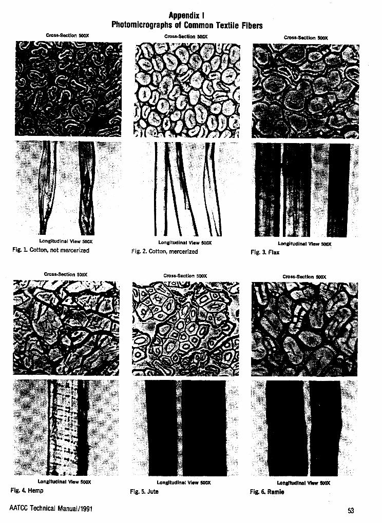
Appendix I Photomicrographs of Common Textile I
CrosbSectkn 5oox CrossSaction 5oox
j
Longitudinal View Sciox Longitudinal View Mox
Fig. 1. Cotton, not mercerized Fig. 2. Cotton, mercerized
’.>
Cross-Section SOOX Cross-Section HlOx
Longitudinal View soox Longitudinal View SOX
Fig. 4 Hemp Fig. 5. Jute
:ibers CmssSaction 50OX
Longitudinal View 5o(u(
Fig. 3. Flax
CrossSection
AATCC Technical Manual/l991 53

cross-section soox Cross-Section MOX Cross-!bction MOX
Longitudinal View 240X Longitudinal View uK)X Longitudinal View 240X
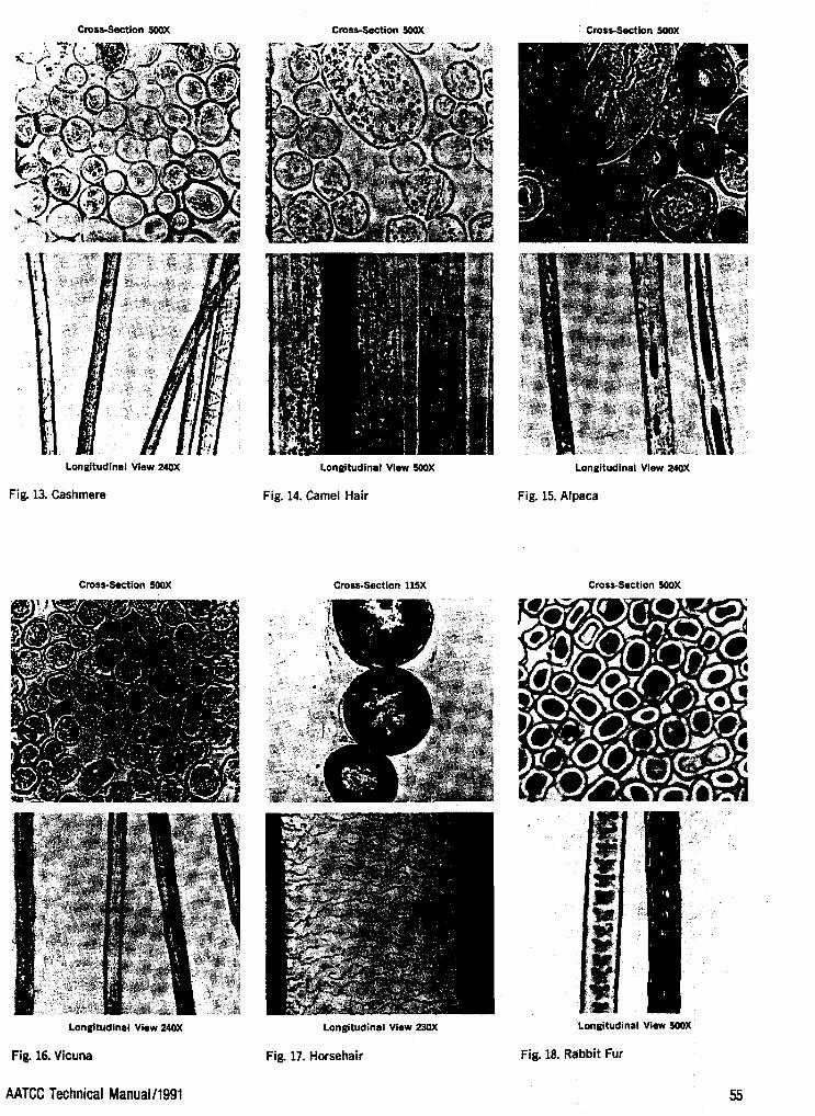
Fig. 13. Cashmere Fig. 14. Camel Hair Fig. 15. Alpaca
Cross-Section SOOX cross-section 115x Cross-Section SOOX
Longitudinal View 23OX Longitudinal View XWX Longitudinal View 2soX
Fig. 16. Vicuna Fig. 17. Horsehair Fig. 18. Rabbit Fur
AATCC Technical ManualA991

Cross-Section 5OOX Cross-section MOX
Longitudinal View 500X
.Fig. 19. Silk
Cross-Section 50OX
Cross-Section 500X
Longitudinal View 500X
Fig. 20. Silk, Tussah
CrostSection 5WX
Longitudinal View 5WX
Fig. 22. Acetate, secondary
Longitudinal View 250X
Fig. 23. Triacetate. 2.5 denier (0.28 tex) per filament, dull luster.
Longitudinal View 5WX
Fig. 21. Asbestos
Cross-Section 500X
Longitudinal View 500X
Fig. 24. Acrylic, Reg. Wet spun, semi- dull.
56 AATCC Technical ManuaM991

3
Cross-Section H)(u( Cross-Section MOX Cross-Section MOX
Longitudinal View 250X
Fig. 25. Acrylic. Modified wet spun, 3.0 denier (0.33 tex) per filament, semi-dull luster.
Cross-section 100X
Longitudinal View lOOX
Fig. 28. Anidex
Longitudinal View 500X
Fig. 26. Acrylic, solvent spun.
Cross-Section 5OOX
Longitudinal View 250X
Fig. 29. Glass
Longitudinal View 250X
Fig. 27. Acrylic. Two-component, 3.0 de- nier (0.33 tex) per filament, semi-dull luster.
Cross-Section lOOX
Longitudinal View lOOX
Fig. 30. Metallic
AATCC Technical ManuaUl991 K 7

Cross-Section 50OX Cross-Section 500K Cross-Section 500X
Longitudinal View 500X
Fig. 31. Modacrylic
Cross-Section 500X
Longitudinal View 500X
Fig. 34. Modacrylic with liquid inclu- sions.
Longitudinal View 500X
Fig. 32. Modacrylic
Longitudinal View 250X
Fig. 33. Modacrylic. 3.0 denier (0.33 tex) per filament, dull luster.
Cross-Section 500X Cross-Section 500X
Longitudinal View 500X
Fig. 35. Nylon, bright
Longitudinal View 250X
Fig. 36. Nylon.. Low modification ratio trilobal, 15 denier 1.65 tex) per filament, bright luster.
58 AATCC Technical Manual/l991
Cross-Section 500X Cross-Section SOOX Cross-Section 5 w X
Longitudinal View 25OX Longitudinal View 25OX Longitudinal View 500X
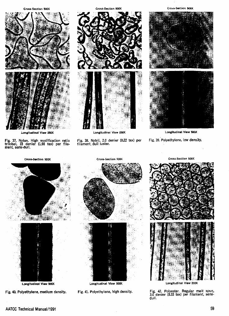
Fig. 38. Nytril. 2.0 denier (022 tex) per Fig. 37. Nylon. High modification ratio trilobal, 18 denier (1.98 tex) per fila- filament, dull luster.
Fig. 39. Polyethylene, low density.
i ment, semidull.
Cross-Section SOOX Cross-Section 500X . > Cross-Section 5OOX
!
Longitudinal View 5OOX
Fig. 40. Polyethylene, medium density.
Longitudinal View 5Mu(
Fig. 41. Polyethylene, high density.
Longitudinal View 250X
Fig. 42. Polyester. Regular melt spun, 3.0 denier (0.33 tex) per filament, semi- dull.
I AATCC Technical Manual/l991 59

Cross-Section 5OOX Cross-Section 5OOX Cross-Section 500X
Longitudinal View 250X Longitudinal View 250X Longitudinal View SOOX
Fi 43. Polyester. Low modification ratio triyobal, 1..4 denier (0.15 tex) per fila- ment, semi-dull luster.
Fig. 44. Rayon, cuprammonium. 1.3 de- nier (0.14 tex) per filament, bright luster.
Fig. 45. Rayon, viscose. Regular tenacity, brt.
Cross-Section 500X Cross-Section 500X Cross-Section 500X
Longitudinal View SOOX Longitudinal View SOOX Longitudinal View 250X
Fig. 47. Rayon,. visocse. High tenacity, low wet elongation.
Fig. 46. Rayon, viscose. High tenacity, high wet elongation.
Fig. 48. Rayon, saponified acetate.. 0.8 denier (0.09 tex) per filament, bright luster.
60 AATCC Technical Manuall1991

Cross-section 5OOX Cross-Section 5oax Crosa-Section MOX
Longitudinal View 25OX
Fig. 49. Rayon, viscose. Modified, 3.0 de- nier (0.33 tex) per filament, bright luster.
Cross-Section 65X
Longitudinal View 250X
Fig. 50. Rayon, viscose. Modified, 1.5 de- nier (0.17 tex) per fllament, bright luster.
Cross-Section SOOX
Loneitudinal View 65X
Fig. 52. Saran
Longitudinal View 250X
Fig. 53. Saran. 16 denier (1.76 tex) per filament, bright luster.
AATCC Technical ManuaM991
Longitudinal View 25OX
Fig.. 51. Rayon, viscose. Modified, 1.5 denier (0.17 tex) per filament, semi-dull luster.
Cross-Section SOOX
Longitudinal View 25OX
Fig. 54. Spandex. Adherin filaments, 12 denier (1.32 tex) per filament, dull luster.
61

Cross-Section 500X
Longitudinal View 250X
Fig. 55. Spandex. Coarse mqnofilaments, 250 denier (27.50 tex) per filament, dull luster.
Cross-Section 600X
Longitudinal View 600X
Fig. 58. Aramid. Round, high-tenacity filament
62
Cross-section 500X
LonRitudinal View 5QOX
Fig. 56. Fluorocarbon
Cross-Section 600X
Longitudinal View 600X
Fig. 59. Aramid. FR staple fiber
Cross-Section 500X
Longitudinal View 500X
Fig. 57. Vinyon
Cross-Section 500X
Longitudinal View SOOX
Fig. 60. Novoloid
AATCC Technical Manual/l99i

AATCC Test Method 20A-1989 An American National Standard
’> Developed in 1957 b AATCC Com-
1975; reaffirmed 1971, 1978, 1981, 1989; editorially revised 1980, 1982 (new title), 1985.
mittee RA24; revise (Y 1958, 1959,
Fiber Analysis: Quantitative
1. Purpose and Scope
1 . 1 This method presents individual procedures for the quantitative determi- nation of moisture content, nonfibrous content and fiber composition of textiles.
1 . 1 . 1 Nonfibrous content of textiles in- cludes such products as fiber finishes, yarn lubricants, slasher sizing, fabric soft- eners, starches, china-clay, soaps, waxes, oil, resins, etc. Clean-fiber con- tent is the amount of fiber after removal of the above type materials.
1.2 The procedures for the determi- nation of fiber composition include me- chanical, chemical and microscopical methods. They are applicable to blends of the following generic classes:
Natural Fibers Cotton Hair Hemp Linen Ramie Silk Wool
Man-Made Fibers Acetate Acrylic Modacrylic Nylon (see 13.1) Olefin Polyester Rayon
2. Uses and Limitations
2.1 The procedure given for the re- moval of nonfibrous materials will re- move most, but not all, of these com- ponents. Each treatment is applicable only to certain categories of these sub- stances and no general scheme can be given that is all inclusive. Some of the newer finishes may present special prob- lems and the analyst will have to deal with these cases as they arise. Thermo- setting resins and cross-linking latices are not only difficult to remove but in some cases cannot be wholly removed without destroying the fiber. When it is necessary to modify a procedure, or use a new one, one should make sure that the fibrpus por- tion of the specimen under test is not attacked. Fiber composition is generally expressed either on the oven-dry weight of the textile as received or on the oven- dry weight of the clean fiber after non- fibrous materials are not first removed from the textile before the fiber analysis is carried out, or if the treatments de-
AATCC Technical Manual/l991
scribed in Section 8 are incapable of re- moving them, any such materials present will increase the percentage of the fiber constituent with which they are removed during the analysis.
2.2 The procedure for determining fi- ber composition by mechanical separa- tion is applicable to those textiles wherein the different fibers making up its compo- sition are segregated in separate yams, or plies, in the textile product.
2.3 The chemical procedures for fiber composition described herein are appli- cable to most of the current, commercial production fibers within each generic class listed. Known exceptions are noted in Table 11. However, there may be in- stances in which a method may not be fully adequate for a newly developed fi- ber falling within one of the listed generic classes and for re-used and/or physically or chemically modified fibers. Caution should be exercised when applying these methods to such cases.
2.4 The microscopical procedures for fiber composition are applicable to all fi- bers and their accuracy depends to a con- siderable extent upon the ability of the analyst to identify the individual fibers present. However, owing to the tedious nature of this technique, its use is gen- erally limited to those mixtures which cannot be separated mechanically or chemically; e.g., mixtures of hair and wool and mixtures of cotton. linen, hemp and/or ramie.
3. Terminology
3.1 Key terms in this test method have not as yet been determined. Definitions will be added when agreed upon.
4. Safety Precautions
NOTE: These safety precautions are for information purposes only. The pre- cautions are ancillary to the testing pro- cedures and are not intended to be all inclusive. It is the user’s responsibility to use safe and proper techniques in hand- ling materials in this test method. Man- ufacturers MUST be consulted for spe- cific details such as material safety data sheets and other manufacturer’s recom- mendations. All OSHA standards and rules must also be consulted and fol- lowed.
4.1 Good laboratory practices should be followed. Wear safety glasses in all laboratory areas.
4.2 All chemicals should be handled with care.
4.3 Perform the soxhlet extractions in Test Method Section 7. Nonfibrous Ma- terial-Clean Fiber Content, using Freon TF (Fluorocarbon 1 1 3) and ethyl alcohol inside an adequately ventilated laboratory hood. CAUTION: Ethyl al- cohol is highly flammable.
4.4 Perform Chemical Analysis Pro- cedure No. 1 (Table 11, 100% Acetone) inside a ventilated laboratory hood. CAUTION: Acetone is highly flamma- ble.
4.5 Ethyl alcohol and acetone are flam- mable liquids and should be stored in the laboratory only in small containers away from heat, open flame and sparks.
4.6 In preparing, dispensing, and handling hydrochloric acid 20%, sulfuric acids (59.5% and 70%), and formic acid (90%) used in Chemical Analysis Pro- cedures Methods No. 2, 3 , 4 , and 6 (Ta- ble 11), use chemical goggles or face shield, impervious gloves and an imper- vious apron. Concentrated acids should be handled only in an adequately venti- lated laboratory hood. CAUTION: Al- ways add acid to water.
4.7 In preparing ammonium hydroxide (8:92) for use in Chemical Analysis Pro- cedure Method No. 4 (Table 11, 70% sulfuric acid), use chemical goggles or face shield, impervious gloves and an im- pervious apron. Dispense, mix and han- dle ammonium hydroxide only in an ade- quately ventilated laboratory hood.
4.8 An eyewashkafety shower should be located nearby and a self-contained breathing apparatus should be readily available for emergency use.
4.9 Exposure to chemicals used in this procedure must be controlled at or below levels set by governmental authorities (e.g., Occupational Safety and Health Administration’s [OSHA] permissible exposure limits [PEL] as found in 29 CFR 1910.1000 of January 1 , 1989). In addition, the American Conference of Governmental Industrial Hygienists (AC- GIH) Threshold Limit Values (TLVs@) comprised of time weighted averages (TLV-TWA), short term exposure limits (TLV-STEL) and ceiling limits (TLV-C) are recommended as a general guide for air contaminant exposure which should be met. Available from: Publications of- fice, ACGIH, 6500 Glenway Avenue, Building D-5, Cincinnati OH 4521 1 .
5. Apparatus
5.1 Analytical Balance, capable of
5.2 Oven, maintained at 105 to llOC. weighing to 0.1 mg.
63
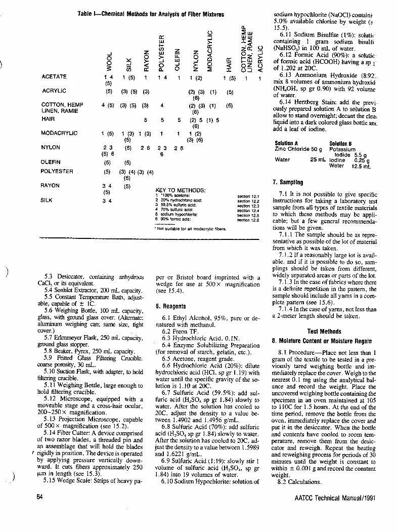
Table l-Chemical Methods for Analysis of Fiber Mixtures
n
ACETATE
ACRYLIC
COTTON, HEMP LINEN, RAMIE HAIR
MODACRYLIC
NYLON
OLEFIN POLYESTER
RAYON
SILK
KEY TO METHODS: 1 *loo% acetone: 2 20% hydrochloric acid: 3 59.5% sulfuric acid 4 70% sulfuric acid: 5 sodium hypochlorite 6 90% formic acid:
* Not suitable for all modacrylc fibers.
section 12.1 section 12.2 section 12.3 section 12.4 section 12.5 Section 12.6
5.3 Desiccator, containing anhydrous
5.4 Soxhlet Extractor, 200 mL capacity. 5.5 Constant T e m p ” Bath, adjust-
CaCI, or its equivalent.
able, capable of h 1C. 5.6 Weighmg Bottle, 100 mL capacity,
glass, with ground glass cover. (Alternate: aluminum weighmg can; same size, tight cover.)
5.7 Erlenmeyer Flask, 250 mL capacity, ground glass stopper.
5.8 Beaker, P y ~ x , 250 mL capacity. 5.9 Fritted Glass Filtering Crucible.
coarse porosity, 30 mL. 5.10 Suction Flask, with adapter, to hold
filtering crucible. 5.11 Weighing Bottle, large enough to
hold filtering crucible. 5.12 Microscope, equipped with a
moveable stage and a cross-hair ocular, 200-250 X magnification.
5.13 Projection Microscope, capable of 500 X magnification (see 15.2).
5.14 Fiber Cutter: A device comprised of two razor blades, a threaded pin and an assemblage that will hold the blades rigidly in position. The device is operated by applying pressure vertically down- ward. It cuts fibers approximately 250 pm in length (see 15.3).
5.15 Wedge Scale: Strips of heavy pa-
per or Bristol board imprinted with a wedge for use at 500x magnification (see 15.4).
6. Reagents
natured with methanol. 6.1 Ethyl Alcohol, 95%, pure or de-
6.2 Freon TF. 6.3 Hydrochloric Acid, 0. IN. 6.4 Enzyme Solubilizing Preparation
(for removal of starch, gelatin, etc.). 6.5 Acetone, reagent grade. 6.6 Hydrochloric Acid (20%): dilute
hydrochloric acid (HCI, sp gr 1.19) with water until the specific gravity of the so- lution is l , 10 at 20C.
6.7 Sulfuric Acid (59.5%): add sul- furic acid (H,SO, sp gr 1.84) slowly to water. After the solution has cooled to 20C, adjust the density to a value be- tween l .4902 and l .4956 glmL.
6.8 Sulfuric Acid (70%): add sulfuric acid (H,S04 sp gr 1.84) slowly to water. After the solution has cooled to 20C, ad- just the density to a value between 1 S989 and 1.6221 g/mL.
6.9 Sulfuric Acid (1:19): slowly stir 1 volume of sulfuric acid (H,S04, sp gr 1.84) into 19 volumes of water.
6.10 Sodium Hypochlorite: solution of
sodium hypochlorite (NaOCI) containi 5.0% available chlorine by weight (s 15.5).
6.11 Sodium Bisulfite (1%): solutic containing 1 gram sodium bisulfi (NaHSO,) in 100 mL of water.
6.12 Formic Acid (90%): a solutic of formic acid (HCOOH) having a sp of 1.202 at 20C.
6.13 Ammonium Hydroxide (8:92, mix 8 volumes of ammonium hydroxid (NH,OH, sp gr 0.90) with 92 volume of water.
6.14 Herzberg Stain: add the previ ously prepared solution A to solution B allow to stand overnight; decant the clea: liquid into a dark colored glass bottle anc add a leaf of iodine.
Solution A Solution B Zinc Chloride 50 g Potassium
Iodide 5.5 g Water 25 mL Iodine 0.25 g
Water 12.5 mL
7. Sampling
7.1 It is not possible to give specific instructions for taking a laboratory test sample from all types of textile materials to which these methods may be appli- cable; but a few general recommenda- tions will be given.
7.1.1 The sample should be as repre- sentative as possible of the lot of material from which it was taken.
7.1.2 If a reasonably large lot is avail- able, and if it is possible to do so, sam- plings should be taken from different, widely separated areas or parts of the lot.
7.1.3 In the case of fabrics where there is a definite repetition in the pattern, the sample should include all yarns in a com- plete pattern (see 15.6).
7.1.4 In the case of yarns, not less than a 2-meter length should be taken.
Test Methods 8. Moisture Content or Moisture Regain
8.1 Procedure-Place not less than 1 gram of the textile to be tested in a pre- viously tared weighing bottle and im- mediately replace the cover. Weigh to the nearest 0.1 mg using the analytical bal- ance and record the weight. Place the uncovered weighing bottle containing the specimen in an oven maintained at 105 to 110C for 1.5 hours. At the end of the time period, remove the bottle from the oven, immediately replace the cover and put it in the desiccator. When the bottle and contents have cooled to room tem- perature, remove them from the desic- cator and reweigh. Repeat the heating and reweighing process for periods of 30 minutes until the weight is constant to within k 0.001 g and record the constant weight.
8.2 Calculations.
64 AATCC Technical Manual/l991

ling see
ion fite
ion ' gr
'2): ide ies
vi- B;
nd :ar
ic ,st Is li- a-
:- a1
1-
t, t. .e e
1-
I-
n
I
I
I
I i I
I
i 1
1 I 1 i f
8.2.1 Calculate the moisture content of the specimen as follows:
x 100 A - B M=- A - T \
where: M = Moisture content, percent. A = weight of sample before
drying + bottle. B = weight of sample after
drying + bottle. T = tare weight of weighing
bottle. 8.2.2 Calculate the moisture regain of
the specimen as follows:
x 100 A - B B - T
R = -
where R = moisture regain, percent; other terms as in 8.2.1
9.1 Nonfibrous Material-Clean Fiber Content
9.1 Procedure-Take a specimen of not less than 5 g, dry it to constant weight in an oven at 105 to 11OC (see 8. l), re- cord the oven-dry weight to the nearest 0.1 mg using an analytical balance and then subject it to one, or more, of the following treatments, as appropriate. When specific type of nonfibrous content is known, only that specific treatment, or treatments, need be performed; other- wise, all treatments must be applied.
9.1.1 Freon Treatment-(For removal of oils, fats, waxes, certain thermoplastic resins, etc.): Extract the dried specimen with Freon TF in a Soxhlet Extractor, syphoning over a minimum of 6 times. Air dry, and then dry at 105 to 110C to constant weight.
9.1.2 Alcohol Treatment-(For re- moval of soaps, cationic finishes, etc.): Extract the dried specimen with ethyl al- cohol in a Soxhlet Extractor, syphoning over a minimum of 6 times. Air dry and then dry at 105 to llOC to constant weight.
9.1.3 Aqueous Treatment-(For re- moval of water soluble materials.) Im- merse the dried specimen for 30 minutes in water at 50C using a 1OO:l liquid to fabric ratio. Stir occasionally or use a mechanical shaker. Rinse 3 times in fresh portions of water and dry at 105 to 1 IOC to constant weight.
9.1.4 Enzyme Treatment-(For re- moval of starch, etc.): Immerse the dried specimen in aqueous solution of the en- zyme preparation following the manu- facturer's recommendations as to con- centration, liquid to fabric ratio, and temperature and time of immersion. Rinse thoroughly with hot water and dry
9.1.5 Acid Treatment-(For removal of amino resins.): Immerse the dried specimen in 100 times its weight of 0.1N HCI at 80C for 25 minutes, stirring oc-
) at 105 to llOC to constant weight.
AATCC Technical Manual/l991
Table Il-Solubilities of Fibers in Reagents Used in the Chemical Methods Chemical Method
NO. 1 NO. 2 No. 3 NO. 4 NO. 5 NO. 6 100% 20% 59.5% 70% 90%
ACETONE HCI H,SO, H,SO, NaOCl HCOOH ACETATE S I S S I S
ACRYLIC
COTTON
HAIR
HEMP
LINEN
MODACRYLIC
NYLON
OLEFIN
POLY ESTER
RAMIE
RAYON
SILK
WOOL
I I
I I
I I
I I
I I
S or I* I
I S
I I
I I
I I
I I
I PS
I I
I
ss I
ss ss I
S
I
I
ss S
S
I
I'
S I
S S
I
S
I
I
S S
S
I
I
I
S
I
I
I
I
I
I
I
I
S
S
I
I
I
I
I
I
S
I
I
I
I
PS
I
'Depending on type
KEY TO SYMBOLS: S = SOLUBLE PS = PARTIALLY SOLUBLE (Method not applicable) SS = SLIGHTLY SOLUBLE (Useable but correction factor required)
I = INSOLUBLE
casionally. Rinse thoroughly with hot water and dry at 105 to 110C to constant weight.
9.2 Calculations 9.2.1 Calculate the nonfibrous content
of the specimen as follows:
x 100 C - D
C N = -
where: N = nonfibrous materials, per- cent.
C = dry weight, specimen, be- fore treatment.
D = dry weight, specimen, after treatment.
9.2.2 Calculate the clean fiber content of the specimen as follows:
D C
F = - X 100
where: F = clean fiber content, percent; other terms as in 9.2.1
10. Mechanical Separation
10.1 Procedure-Remove the non-fi- brous materials using the appropriate treatment (see 9.1). Separate the com- ponent yarns by mechanical dissection; combine those yarns, or plies, having the same fiber composition and determine the oven-dry weight of each generic type present.
10.2 Calculation-Calculate the con-
tent of each generic fiber as follows: W E
x,- x 100
where: X, = content of fiber i, percent. W, = oven-dry weight of fiber i,
after separation. E = weight of clean, oven-dry
specimen taken for analy- sis.
11. Chemical Analysis-General
1 1.1 Specimen Preparation-Before analyses are undertaken, the laboratory test sample should be disintegrated, ho- mogenized and a portion of the homo- genate taken for the chemical treat- ment(s). In the case of a fabric, one should unravel it into its individual yarns, cut the yarns into lengths not greater than 3 mm, thoroughly mix the cut pieces and then take a representative portion for the specific determination. An alternate pro- cedure, suitable in many cases, is to grind the sample using a Wiley Mill, homo- genize the ground fibers by slurrying them in a water suspension in a Waring Blender and taking the representative portion from the dried homogenate for the specific determination. Yams are treated the same way but omitting the unnecessary steps.
11.2 Method Application-A tabula- tion of appropriate chemical treatments
65

for binary fiber mixtures is given in Table I. To use this table one enters at the left side on the line listing one of the com- ponents of the binary mixture and moves to the box under the column listing the other component and the number therein is the method, or methods, that are ap- plicable for that specific combination. The unbracketted methods are those that dissolve the fiber at the left side of the diagram while the bracketted ones dis- solve the fiber at the top of the diagram. Mixtures of more than two components may be analyzed by proper application of a sequence of the individual methods. Table I1 presents the relative solubilities of the various fibers in all the reagents and, from this, one can select the proper methods and their sequence for the analy- sis of multifiber mixtures (see 15.7).
I ' ' ' I ' ' . ' I " , , i . ' , , l ' , , , l , , . , l , ~ . . , l 1 , - u s . PULLEO WOOL AA A B C
u s . WOOL BLOOD Claesttltotion Ronqas I !$Z;Stt&lZR&WZ - 7 0 - E 4 : E e - E O ~ 5 4 - 5 0 . 4 ~ 4 0 ~ 4 ~
us. WOOL TOP .O TO E4 e2 EO5.5E54504.U44403E
CIas"lco"on - ' F I N E && I ~ ~ , , , , n ~ ' ,BRAID WOOL
Clossiflcation Ranges - 40 30 32 30 2. 2. 22 IE
MOHAIR - I - -. - ~ - - 1 CASMULRL ALPACA
SPECIALTY ... -%. - 4 -
12. Chemical Analysis Procedures
12.1 METHOD No. 1, 100% ACETONE: Weigh accurately a 0.5 to 1.5 g portion of the clean, dry, prepared specimen and record the weight to the nearest 0.1 mg. Transfer into a 250 mL Erlenmeyer flask. Add 100 times its weight of acetone and agitate vigorously for 15 min keeping the temperature at 40 to 50C. Decant the liq- uid from the undissolved residue, add a fresh portion of acetone and agitate for a few more minutes. Repeat the decanting and agitation process one more time and then filter the undissolved residue by suc- tion through a dried weighted, fritted- glass, filtering crucible. Dry the crucible and residue in air and then in an oven at 105 to 110C to constant weight. Record the weight of the dried residue to the nearest 0.1 mg.
12.2 METHOD No. 2, 20% HYDRO- CHLORIC ACID: Weigh accurately a 0.5 to 1.5 g portion of the clean, dry, pre- pared specimen and record the weight to the nearest 0.1 mg. Transfer into a 250 mL Erlenmeyer flask. Add 50 to 150 mL of 20% hydrochloric acid (100 mL re- agenUg of sample); shake vigorously and let stand for 5 min at 15 to 25C. Shake again and let stand for 15 min. Shake for a third time (see 15.8) and filter the mix- ture through a dried weighed fritted-glass crucible. Wash into the crucible any res- idue left in the flask using a little more 20% hydrochloric acid. Apply suction to drain the excess liquor from the filter res- idue. Wash the residue in the crucible with about 40 mL of 20% hydrochloric acid and then with water until the filtrate is neutral to litmus. Disconnect the suc- tion and add to the crucible about 25 mL of ammonium hydroxide (8:92) allowing the fiber residue to soak for 10 min before applying suction to drain it. Wash the residue with about 250 mL of water, al- lowing it to soak in the water for about 15 min. After the final washing, apply suction to remove rinse water, and dry
\
' MLHP ' V E G E T A B L E FIBERS -
JUTE
I O E N t L R .a .3 .4 .a .. .7 9 .9 to 1.2 1.6 .la !. 20 IS ,VISCOSE RAYON O L N l C R ,2
1 OLNILR .2
7 1 OLNILI1 5 -CASEIN FlaER 70's ORAOL EO'S 50'.
the crucible and residue in an oven at 105 to llOC to constant weight. Record the dry weight to the nearest 0.1 mg.
12.3 METHOD No. 3 , 59.5% SUL- FURIC ACID: Weigh accurately a 0.5 to 1.5 g portion of the clean, dry, prepared specimen and record the weight to the nearest 0.1 mg. Transfer into a 250 mL Erlenmeyer flask. Add 50 to 150 mL of 59.5% sulfuric acid (100 mL reagent/g of sample) and shake vigorously for 1 min. Let stand for 15 min at a temper- ature of 15 to 25C. Shake again and let stand for another 15 min, shake for a third time (see 15.8) and then filter the mixture through a dried weighed fritted-glass cru- cible. Wash into the crucible any residue left in the flask using three 10 mL aliquots of 59.5% sulfuric acid. Apply suction to drain the excess liquor from the fiber res- idue after the addition of each aliquot. Wash the residue in the crucible with 50 mL of sulfuric acid (1:19), then with water until the filtrate is neutral to litmus. Disconnect the suction and add to the crucible about 25 mL of ammonium hy- droxide (8:92), allowing the fiber residue to soak for 10 min before applying suc- tion to drain it. Wash the residue with about 150 mL of water, allowing it to soak in the water for about 15 min. After the final washing, apply suction to re- move the rinse water and dry the crucible and fiber residue in an oven at 105 to llOC to constant weight. Record the weight of the dried residue to the nearest 0.1 mg (see 15.9).
12.4 METHOD No. 4, 70% SULFURIC ACID: Weigh accurately a 0.5 to 1.5 g portion of the clean, dry, prepared spec- imen and record the weight to the nearest 0.1 mg. Transfer into a 250 mL Erlen- meyer flask. Add 50 to 150 mL of 70% sulfuric acid (100 mL reagent/g of sam- ple) and shake vigorously for 1 min. Let
stand for 15 min at a temperature of 15 to 25C. Shake again and let stand for another 15 min; shake for a third time (see 15.8) and then filter the mixture through a fritted-glass crucible which has been oven-dried, cooled in a desiccator, and weighed to 0.1 mg. Wash into the crucible any residue left in the flask using three 10 mL aliquots of 70% sulfuric acid. Apply suction to drain the excess liquor from the fiber residue after the ad- dition of each aliquot. Wash the residue in the crucible with 50 mL of sulfuric acid (1: 19), then with water until the fil- trate is neutral to litmus. Disconnect the suction and add to the crucible about 25 mL of ammonium hydroxide (8:92); al- low the fiber residue to soak for 10 min before applying suction to drain it. Wash the residue with about 150 mL of water, allowing it to soak in the water for about 15 min. After the final washing, apply suction to remove excess water and dry the crucible and fiber residue in an oven at 105 to llOC to constant weight. Re- cord the weight of the dry residue to the nearest 0.1 mg.
12.5 METHOD No. 5, SODIUM HY- POCHLORITE: Weigh accurately a 0.5 to 1.5 g portion of the clean, dry, prepared specimen and record the weight to the nearest 0.1 mg. Transfer into a 250 mL Erlenmeyer flask. Add 50 to 150 mL of sodium hypochlorite reagent (100 mL re- agenUg of sample). Stir the specimen in this solution for 20 min making sure the temperature is maintained at 25 f IC Xuse constant temperature bath) see (15.10) and then filter through a dried weighed, fritted-glass crucible. Wash thoroughly with sodium bisulfite (1%) followed by water and remove the excess water by suction. After the final washing, apply suction to remove excess water and dry in an oven at 105 to 11OC to constant
66 AATCC Technical ManuaUl991

3
P
J
Table IV-Fineness Ranges and Fiber Diameters of Various Textile Fibers* in Micrometers (pm)
U.S. Wool Classification
Wool Grades Wool Top Grades Pulled Wool
Numerical Average Blood Numerical Average System Diameterb System' System Diameterd Grades
80's ............ 17.7 to 19.1 Fine 80's ........... 18.1 to 19.5 AA 70's ............ 19.2 to 20.5 Fine 70s ........... 19.6to 21.0 AA 64's ............ 20.6 to 22.0 Fine 64's ........... 21.1 to 22.5 AA 62's ............ 22.1 to 23.4 V2 62's ........... 22.6 to 24.0 A 6 0 s ............ 23.5 to 24.9 V2 60's . . . . . . . . . . . 24.1 to 25.5 A 58's ............ 25.0 to 26.4 % 58's ........... 25.6 to 27.0 A 56's ............ 26.5 to 27.8 44 56s ........... 27.1 to 28.5 B 54's ............ 27.9 to 29.3 '/4 54's ........... 28.6 to 30.0 B
46s ............ 32.7 to 34.3 LOW r/, 46's ........... 33.5 to 35.1 C 44's ............ 34.4 to 36.1 Common 44's ........... 35.2 to 37.0 C 40's ............ 36.2 to 38.0 Braid 40s ........... 37.1 to 38.9 C 36's ............ 38.1 to 40.2 Braid 36's ........... 39.0 to 41.2 C
5 0 s ............ 29.4to 30.9 '/4 50s ........... 30.1 to31.7 B 48's ............ 31.0 to 32.6 r/, 48's ........... 31.8 to 33.4 B
Hair Fibers and Silk
Mohair (1) Miscellaneous Hair Fibers (1) Silk (1)
Fineness Average Average Grade Range Fiber Fineness Fiber Fineness
40s ......... 23.55 to 25.54 Vicuna . . . . . . . 13.0 to 14.0 Cultivated silk. 10.0 to 13.0 36s ......... 25.55 to 27.54 Cashmere . . . . 15.0 to 16.0 Tussah Silk . . 32s ......... 27.55 to 29.54 Camel hair . . . . 17.0 to 23.0 30s . . . . . . . . . 29.55 to 31.54 Alpaca . . . . . . . 26.0 to 28.0 28s ......... 31.55 to 33.54 Llama . . . . . . . . 20.0 to 27.0 26s ......... 33.55 to 35.54 22s ......... 35.55 to 38.04 18s ......... 38.05 to 40.54
28.5
Vegetabie Fiber (1) Glass Fiber (2)
Filament Staple Fiber Average Diameter Theoretical Diameter Average
Fiber Fineness Designation Diameter' Designation Diameter
. . . . . . . . . . Cotton 16.0 to 21.0 D ........... 5.3 E 7.1 G . . . . . . . . . . 9.7
Hemp ........... 18.0 to 23.0
.......... Flex (linen) ...... 15.0 to 17.0 Jute ............ 15.0to 20.0 G ........... 9.0 J . . . . . . . . . . 11.4
E . . . . . . . . . . . . 7.4
Kapok .......... 21.0 to 30.0 Ramie .......... 25.0 to 30.0
Rayon (3), Acetate (3), Nylon (4), and Vinyon (3) Casein Fiber (5)
Theoretical Fiber Diametere
Filament Viscose Acetate Fiber Denier Rayon and Vinyon Nylon Grade Denier Diameter
1 ............... 2 ............... 3 ............... 4 ............... 5 ............... 6 ............... 7 ............... 8 ............... 9 ...............
10 . . . . . . . . . . . . . . . 12 . . . . . . . . . . . . . . . 14 . . . . . . . . . . . . . . . 16 ............... 18 ............... 20 ...............
Source of Data:
9.6 13.6 16.7 19.3 21.6 23.6 25.5 27.3 28.9 30.5 33.4 36.1 38.6 40.9 43.1
10.3 14.5 17.8 20.6 23.0 25.2 27.3 29.1 30.9 32.6 35.7 38.5 41.2 43.7 46.1
11.1 15.7 19.3 22.3 24.9 27.3 29.5 31.5 33.4 35.2 38.5 41.7 44.5 47.3 49.9
70's . . . . . . 3 20 60's . . . . . . 5 25 50s . . . . . . 7 30
(1) Wemr van Bergen and w. Krauss, rexlile Fiber A m , Textile Book Publishers inc., New YO& NY (1949). (2) OwensCorning Fiberglas Corp. (3) American Viscose Corp. (4) E. 1. du Pont de Nemours and Co (5) Aralac Incorporated.
Trade application.
Grade (ASTM Designation: D 472). ~c i f lca t lons for Fineness of Mohair Tops and Assignment of Grade (ASTM Designation: 0 1381).
' U. S. Standards. Federal Register, January 13,1954; Specifications for Fineness of Wool Tops and Assignment of
'Caicuiated from the denier and specific gravity, and based on a theoretical circular cross-section of the fiber.
weight. Record the weight of the dried residue to the nearest 0.1 mg.
12.6 METHOD No. 6, 90% FORMIC ACID: Weigh accurately a 0.5 to 1.5 g portion of the clean, dry, prepared spec- imen and record the weight to the nearest 0.1 mg. Transfer into a 250 mL Erlen- meyer flask. Add 50 to 150 mL of 90% formic acid (100 mL reagentlg of sample) and shake frequently over a period of 15 min (see 15.1 1) . Decant the supernatant liquid into a dried, weighed, fritted-glass crucible, add another equal portion of 90% formic acid to the flask and agitate for an additional 15 min. Filter the con- tents of the flask through the crucible, rinse with two 50 mL portions of 90% formic acid and drain with the aid of suc- tion. Wash the residue with 50 mL of water and then allow it to soak in 25 mL of ammonium hydroxide (8:92) for about 10 min. Wash the residue thoroughly with water until the filtrate is neutral to litmus. Drain the residue with the aid of suction and dry in an oven at 105 to 1 1OC to constant weight. Record the weight of the dried residue to the nearest 0.1 mg.
12.7 Calculations: Calculate the con- tent of each generic fiber type as deter- mined by any one of the above applicable chemical methods using one of the fol- lowing equations:
12.8 If the fiber is dissolved by the test reagent:
x, = - - x 100 G 12.8.2 If the fiber is insoluble in the
test reagent: Hi xi = - x 100 G
where: Xi = content of fiber i, percent. G = weight of clean, dry, pre-
pared specimen H, = weight of dried residue
after treatment
13. Microscopical Analysis, General
13.1 The following procedure may be used for the quantitative analysis of tex- tiles containing two or more fiber types which cannot be separated readily by me- chanical or chemical methods. The pro- cedures rely on the ability of a technician to identify and count, by means of a mi- croscope, the relative number of fibers of each type in a prepared specimen. Such a count will result in a percent blend by number of fibers. In order to convert this result to a percent by weight, the size of the fibers being counted and their re- spective densities must be included in the calculation.
13.2 Microscope slides may be pre- pared to scan longitudinal or cross-sec- tion views of a fiber sample. The fiber images may be viewed either through a
AATCC Technical ManuaVl991 G7

microscope or as projected onto a hori- zontal plane. While either viewing method may be used for identification and counting of fibers, the projection method is specifically used for measuring fiber diameters using a wedge scale (Sec- tion 14.3.2).
13.3 Methods which may be used to identify fibers during the fiber counting procedures are discussed in AATCC Test Method 20. They include the following:
AATCC 20 Herzberg stain (zinc chloro- Section 7.9.1
Acid phloroglucinol reagent Section 7.9.2 Longitudinal appearance Tables I and II Cross-section appearance Tables 1 and I1
and Appendix I
iodide)
It is recommended that reference tests be made on known fibers rather than plac- ing total reliance on photographic repro- ductions and word descriptions of colors.
14. Microscopical Analysis Procedures
14.1 Preparation of Slides. 14.1.1 Longitudinal Sections of
Vegetable Fibers (cotton, flax, ramie, etc.): A swatch of fabric measuring at least 5 X 5 cm should be available. Count the number of yams in both the warp and filling and select from each direction at random a number of yarns that is proportional to the fabric count. The combined number of warp and fill- ing yarns should total at least 20 (see 15.12). If the sample is in yarn form, take at least a two-meter length and, from it, cut not less than twenty 5-cm sections at random. Cut approximately 2.5 cm of each yarn, or yarn section, into lengths of 0.5 to 1 mm. The shorter the lengths the easier it is to prepare a homogeneous fiber suspension. Collect the cut fibers on a paper of contrasting color and transfer to a 125 mL Erlen- meyer flask. Add sufficient water so that after stoppering the flask and shak- ing the contents, a uniform and fairly dense fiber suspension is obtained. Quick boiling or the addition of a few glass pellets facilitates the separation of the fibers. Using a glass-marking pen- cil, draw two parallel lines about one inch apart across a glass slide. With a wide-mouth pipette, draw 0.5 to 1 mL of the well shaken suspension and place it between the two reference lines on the slide. The amount of liquid taken is dependent upon the density of the sus- pension. Just sufficient liquid should be placed on the slide so that-after evap- oration-a thin, uniform film of fibers remains. After all of the moisture has evaporated from the slide, stain the fi- bers with Herzberg stain and cover with a cover glass.
14.1.2 Longitudinal Sections of Wool, Hair and other round Fibers: Select a rep- resentative swatch, or yarn sections, as
in 14.1.1. With a fabric swatch, remove the outermost yarns in both directions so that the warp and filling yarns are pro- tuding approximately I cm. Lay the sam- ple flat on a table and, using a fiber cutter, force the blades vertically downward into the warp fringe. Repeat the operation with the filling fringe. Remove the device with the top plate up, release the tension on the cutting blades and remove them together by their ends between the thumb and forefinger. Carefully separate the blades so that the cut fiber sections will adhere to the edge of one or both blades. Place a few drops of mineral oil on a clean slide and, with a dissecting needle, scrape the fiber sections onto the oil. Thoroughly disperse the fibers in the oil with the dissecting needle and cover with a cover glass. For yam samples, align the sections side-by-side and perform the above operation starting with the use of the fiber cutter.
14.1.3 Cross-sections of Fibers: Select representative yarns, or yam sections, from the sample and render them to staple by removing twist and drawing out fibers. Align the fibers parallel to each other so as to form a well blended tuft. Prepare a slide following the instructions of AATCC Test Method 20, Section 7.3.
14.2 Fiber Counting. 14.2.1 Fibers Viewed Through Micro-
scope: Place the slide prepared as in Sec- tion 14.1 on the moveable stage on a microscope equipped with a crosshair ocular and having a magnification of 200 to 250X. Begin to count near either the upper or lower comer of the field and, as the slide is moved slowly across the field in the horizontal direction, identify and count all fibers passing through the center of the crosshairs. After each trip across the field, move the slide 1 to 2 mm vertically and identify and count the fibers as the field is again traversed. Re- peat this procedure until the whole slide has been covered. The spacing between each traverse is dependent upon the num- ber of fiber sections on the slide. If a fiber passes the crosshair more than once, record each passing (see 15.13). In a sim- ilar manner, count the fibers by moving the slide vertically. The combined hori- zontal and vertical counts should total at least 1000 fibers.
14.2.2 Projected Images of Fibers: Calibrate the microprojector so that it will give a magnification of 500X in the plane of the projected image. To do this, place a stage micrometer (having units of 0.01 mm) on the stage of the microprojector with its scale toward the objective and place a large sheet of white, nonglare paper in the projection plane. Lower or raise the microscope until an interval of 0.20 mm on the stage micrometer will measure 100 mm when sharply focused in the center of the paper. Place the slide prepared as in section 14.1 on the stage
of the microprojector with the cover glass toward the objective. Draw a 10-cm di- ameter circle in the center of the white paper in the projection plane. All mea- surements and counts are to be made within this circle. Begin to count near either the upper or lower comer of the field and proceed exactly as described in 15.2.1 (see 15.14).
14.3 Fiber Measurement. 14.3.1 Fibers with Noncircular Cross-
section: Prepare a slide as described in 14.1.3. Place this slide on the stage of the microprojector and project the image onto a sheet of graph paper having one millimeter squares. Trace the image of the fibers on the graph paper using a sharpened pencil, taking care not to re- trace fibers previously traced. If there are not sufficient fibers on the slide to pro- vide 100 of each type, prepare another slide as described above using another tuft of fibers. Continue to trace and to count on the new slide until 100 fibers of each type have been tallied. By count- ing squares, and parts of squares, deter- mine the cross-sectional area of each in- dividual fiber of each type. Calculate the mean cross-sectional area for each fiber type present by summing the individual values recorded for that type and dividing the sum by the total number of fibers of that type measured. Final values should be in mm’.
14.3.2 Fibers with Circular Cross-Sec- tions: Prepare a slide as described in 14.1.2. Be sure to make measurements on the same day that the slide was pre- pared. Position the slide in the micro- projector so that all areas of the slide can be reached. Bring each individual fiber being measured into sharp focus on the wedge scale. Adjust the position of the scale until the fiber image is projected on the wedge with a fine line and mark on the wedge the point that corresponds to the width of the fiber midway of its length. Traverse the slide and measure successive fibers of each type following a planned course. Measure fibers only when their midpoint falls within the 10- cm circle central located in the field. Ex- clude from measurement those fibers that cross another fiber at the point of mea- surement and those that are shorter than 150 pm. A minimum of 100 fibers of each type present should be measured. Square each fiber diameter in the blend being analyzed and calculate the mean of each fiber type. Final values should be in pm’ (see 15.15). Considerable varia- tion can occur in the average diameter of hair and wool fibers. Thus, for accurate results on any specific sample, the fiber diameters must be measured. If, how- ever, maximum accuracy is not required, the diameters given in Tables III and IV may be used.
14.4 Calculations. Calculate the con- tent of each fiber as percent by weight
68 AATCC Technical Manuall1991

using equation 1 if section 14.3.1 was used to determine average area of fiber cross-section images, and equation 2 if section 14.3.2 was used to determine fi- ber diameters (see 15.16). 'I
N i x A, x Si C(N x A x S)
xi Eq. 1
N i x D: x Si C(N x D2 x S) x i = Eq. 2
Where X, is content of fiber i, percent (by weight)
N, is relative number of fibers of type i
A, is average area of fiber im- ages of fiber i
DT is the mean of diameter squared of fibers of type i
S, is specific gravity of type i fiber
C(N, x A, x S,) is sum of the respective N x A x S products for each fiber type in the blend
Z(N x D2 x S) is sum of the respective N x D2 x S products for each fiber type in the blend
See Table V for specific gravity val- ues.
15. Notes
) 15.1 Applicable only to Nylon 6 and Nylon 6.6.
15.2 A projection microscope may be ob- tained from Kenneth A. Dawson Co., 106 Concord Avenue, Belmont MA 02178, or Un- itron Instrument Co., 66 Needham Street, Newton Highland MA 02161.
15.3 A Swiss Fiber Cutting Device is avail- able from Harold Wolf, Clifton NJ. An FRL Fiber Cutter is available from Albany Inter- national Research Co., 777 West Street, Mans- field MA 02048-91 14.
15.4 Wedge Scales may be obtained from E. J. Powers Press, 201 South Street, Boston MA 02111; and Essex Ruling and Printing Co., Lawrence MA 01840.
15.5 Since sodium hypochlorite solutions lose strength on standing, it is recommended that they be standardized frequently. The fol- lowing is a suitable method for determining
the available chlorine content of such solu- tions: Dilute a 10 mL aliquot of the solution to be tested to 250 mL with water in a vol- umetric flask. Pipette 25 mL from the volu- metric flask to an Erlenmeyer flask; add 3 to 5 mL of a 10% solution of potassium iodide (KI) and then add 2 to 3 mL acetic acid (CH,COOH). Mix well and titrate with 0.1N sodium thiosulfate (Na,S,O,) until the yellow color of the iodine is nearly destroyed. Add 5 ml of a starch indicator solution and titrate until the blue color entirely disappears. Cal- culate the percentage of available chlorine by weight as follows:
Available Chlorine, % = 3.5A/B where: A = ml of 0.1N sodium thiosulfate
used B = g of 10 mL aliquot taken
15.6 Exception: when the pattem is smaller than 15 x 15 cm, a sufficient number of com- plete pattems should be taken to be equivalent to not less than 225 cm2.
15.7 Whenever there is any doubt about the effectiveness of a given method in dissolving a specific fiber, or whenever there is an ap- plication of a method to a new type of fiber, one should always examine the residue in the filtering crucible after weighing. This precau- tion should always be taken when a fiber blend
Table V
Fiber Acetate Acrylic Cotton Hair Hemp Linen Modacrylic Nylon Olefin
Specific Gravity 1.31
1.16-1.22 1.55 1.32 1.48 1.50
1.14 0.93
1.28-1.38
Polyester 1.23-1.40 Ramie 1.51 Rayon 1.52 Silk 1.25 Wool 1.31
In the case of a fiber with a range of values, knowledge of the specific type in the generic class may permit the selection of a precise specific gravity; or the density of a fiber may be determined using the procedure de- scribed in AATCC Test Method 20, Section 9.6.
consists of (1) one predominate fiber with one (or more) minor components; or (2) one very minor fiber with one (or more) major com- ponents.
15.8 If a mechanical shaking machine is available, the flask may be shaken on it con- tinuously for 30 min.
15.9 Cotton is not completely insoluble in H,SO, (59.5%). Furthermore, a small amount of rayon remains undissolved in this solvent. In the analysis of cotton/rayon blends, inter- laboratory tests indicate that to allow for the above bias, the composition of the specimen should be calculated as follows:
100 d F Corrected cotton, % = - - 1.6
ais 1.062 for bleached cotton, ais 1.046 J is the ovendry residue weight F is the ovendry weight of clean fiber before treatment.
Where for raw cotton,
Corrected Regenerated Cellulose Rayon, % =
100 - corrected cotton percent. 15.10 Extreme care must be taken to control
both time of exposure to the reagent and the temperature of treatment. If either is insuffi- cient, the desired fiber or fibers, will not be completely dissolved. If either becomes ex- cessive, it will cause attack of other fibers.
15.11 A mechanical shaking machine may be used for this purpose.
15.12 For fancy woven fabrics, use all the yams in one or more complete pattems or a representative fraction, if the pattem is large.
15.13 Linen fibers may be present in the fabric or yam in the form of fiber bundles. Most bundles are reduced to single fibers dur- ing the preparation of the fiber suspension. If, however, some bundles do appear on the slide, an attempt should be made to count each of the individual fibers in the bundle.
15.14 A regular microscope may be used for the fiber counting and, if a suitable cali- brating device is available, it may also be used for measuring fiber diameters.
15.15 For further information on marking cell numbers on a wedge scale, and for ex- amples of calculations of how to determine the average fiber diameter using cell numbers, see ASTM D 2130, Method of Test for Di- ameter of Wool and Other Animal Fibers by Microprojection.
15.16 One is cautioned not to mix units; e.g., if some fiber diameters have been de- termined in mm, then all diameters must be in mm. Also, one cannot use both diameters and cross-sectional areas in the same equation.
4ATCC Technical Manuall1991 69


![[XLS] · Web view56.890756302520998 30821 172.18487394958001 30822 34.495798319327697 30823 92.142857142857196 30824 99.789915966386602 30825 31.512605042016801 30826 36.134453781512597](https://img.pdfslide.net/doc/110x75/5aba338d7f8b9af27d8b6683/xls-view56890756302520998-30821-17218487394958001-30822-34495798319327697-30823.jpg)