Embed Size (px)
Citation preview
ABB industrial drives
Application guideACS800-01/04/11/31/104/104LC Safe torque off function (+Q967)
Phone: 800.894.0412 - Fax: 888.723.4773 - Web: www.clrwtr.com - Email: [email protected]

Phone: 800.894.0412 - Fax: 888.723.4773 - Web: www.clrwtr.com - Email: [email protected]
Application guide
ACS800-01/04/11/31/104/104LC Safe torque off function(+Q967)
3AUA0000063373 Rev DEN
EFFECTIVE: 2011-05-27
© 2011 ABB Oy. All Rights Reserved.
3. Installation
4. Start-up and validation
Table of contents
Phone: 800.894.0412 - Fax: 888.723.4773 - Web: www.clrwtr.com - Email: [email protected]

Phone: 800.894.0412 - Fax: 888.723.4773 - Web: www.clrwtr.com - Email: [email protected]
5
Table of contents
1. Basics
Option codes (plus codes) . . . . . . . . . . . . . . . . . . . . . . . . . . . . . . . . . . . . . . . . . . . . . . . . 8
2. Program features, settings and diagnostics
Operation of the STO function and its diagnostics function . . . . . . . . . . . . . . . . . . . . . . . 9STO status indications . . . . . . . . . . . . . . . . . . . . . . . . . . . . . . . . . . . . . . . . . . . . . . . . . . 10STO function activation and indication delays . . . . . . . . . . . . . . . . . . . . . . . . . . . . . . . . 10
Module delays only . . . . . . . . . . . . . . . . . . . . . . . . . . . . . . . . . . . . . . . . . . . . . . . . . . . 10Delays with typical STO safety relay . . . . . . . . . . . . . . . . . . . . . . . . . . . . . . . . . . . . . 10
3. Installation
Example wiring diagrams . . . . . . . . . . . . . . . . . . . . . . . . . . . . . . . . . . . . . . . . . . . . . . . . 11Without safety relay . . . . . . . . . . . . . . . . . . . . . . . . . . . . . . . . . . . . . . . . . . . . . . . . . . 12
Frame sizes R2 to R6 . . . . . . . . . . . . . . . . . . . . . . . . . . . . . . . . . . . . . . . . . . . . . . 12Frame sizes R2i to R4i . . . . . . . . . . . . . . . . . . . . . . . . . . . . . . . . . . . . . . . . . . . . . . 12Frame size R5i . . . . . . . . . . . . . . . . . . . . . . . . . . . . . . . . . . . . . . . . . . . . . . . . . . . . 13Frame size R7i . . . . . . . . . . . . . . . . . . . . . . . . . . . . . . . . . . . . . . . . . . . . . . . . . . . . 13Frame size R8i . . . . . . . . . . . . . . . . . . . . . . . . . . . . . . . . . . . . . . . . . . . . . . . . . . . . 14Liquid-cooled modules of frame sizes R7i and R8i . . . . . . . . . . . . . . . . . . . . . . . . 14Connecting the STO switch without safety relay . . . . . . . . . . . . . . . . . . . . . . . . . . 15
With safety relay . . . . . . . . . . . . . . . . . . . . . . . . . . . . . . . . . . . . . . . . . . . . . . . . . . . . . 16Frame sizes R2 to R6 . . . . . . . . . . . . . . . . . . . . . . . . . . . . . . . . . . . . . . . . . . . . . . 16Frame sizes R7 and R8 . . . . . . . . . . . . . . . . . . . . . . . . . . . . . . . . . . . . . . . . . . . . . 16Frame sizes R2i to R4i . . . . . . . . . . . . . . . . . . . . . . . . . . . . . . . . . . . . . . . . . . . . . . 17Frame size R5i . . . . . . . . . . . . . . . . . . . . . . . . . . . . . . . . . . . . . . . . . . . . . . . . . . . . 17Frame size R7i . . . . . . . . . . . . . . . . . . . . . . . . . . . . . . . . . . . . . . . . . . . . . . . . . . . . 18Frame size R8i . . . . . . . . . . . . . . . . . . . . . . . . . . . . . . . . . . . . . . . . . . . . . . . . . . . . 18Connecting several drive modules to one safety relay . . . . . . . . . . . . . . . . . . . . . 19
4. Start-up and validation
Validating the operation of a safety function . . . . . . . . . . . . . . . . . . . . . . . . . . . . . . . . . . 21Authorized person . . . . . . . . . . . . . . . . . . . . . . . . . . . . . . . . . . . . . . . . . . . . . . . . . . . 21Acceptance test reports . . . . . . . . . . . . . . . . . . . . . . . . . . . . . . . . . . . . . . . . . . . . . . . 21
Start-up checklist . . . . . . . . . . . . . . . . . . . . . . . . . . . . . . . . . . . . . . . . . . . . . . . . . . . . . . . 22
5. Maintenance and fault tracing
Maintenance . . . . . . . . . . . . . . . . . . . . . . . . . . . . . . . . . . . . . . . . . . . . . . . . . . . . . . . . . . 23Warning messages generated by the drive . . . . . . . . . . . . . . . . . . . . . . . . . . . . . . . . . . . 23Fault messages generated by the drive . . . . . . . . . . . . . . . . . . . . . . . . . . . . . . . . . . . . . 24
6. Technical data
STO components . . . . . . . . . . . . . . . . . . . . . . . . . . . . . . . . . . . . . . . . . . . . . . . . . . . . . . 25
Phone: 800.894.0412 - Fax: 888.723.4773 - Web: www.clrwtr.com - Email: [email protected]
6
ASTO-11/21 board . . . . . . . . . . . . . . . . . . . . . . . . . . . . . . . . . . . . . . . . . . . . . . . . . . 25ASTO board according to frame size of the module . . . . . . . . . . . . . . . . . . . . . . . 25
STO safety relay type . . . . . . . . . . . . . . . . . . . . . . . . . . . . . . . . . . . . . . . . . . . . . . . . 26Push-button to be used with emergency stop . . . . . . . . . . . . . . . . . . . . . . . . . . . . . . 26STO switch to be used with Prevention of unexpectedstart-up function implemented with STO . . . . . . . . . . . . . . . . . . . . . . . . . . . . . . . . . . 26
STO data related to safety standards (safety relay not included) . . . . . . . . . . . . . . . . . 26Frame size R2/R2i . . . . . . . . . . . . . . . . . . . . . . . . . . . . . . . . . . . . . . . . . . . . . . . . . . 26Frame size R3/R3i . . . . . . . . . . . . . . . . . . . . . . . . . . . . . . . . . . . . . . . . . . . . . . . . . . 26Frame size R4/R4i . . . . . . . . . . . . . . . . . . . . . . . . . . . . . . . . . . . . . . . . . . . . . . . . . . 27Frame size R5/R5i . . . . . . . . . . . . . . . . . . . . . . . . . . . . . . . . . . . . . . . . . . . . . . . . . . 27Frame size R6 . . . . . . . . . . . . . . . . . . . . . . . . . . . . . . . . . . . . . . . . . . . . . . . . . . . . . . 27Frame size R7/R7i/R8/R8i . . . . . . . . . . . . . . . . . . . . . . . . . . . . . . . . . . . . . . . . . . . . 27Multiples of frame size R8i . . . . . . . . . . . . . . . . . . . . . . . . . . . . . . . . . . . . . . . . . . . . 27
Frame size 2×R8i . . . . . . . . . . . . . . . . . . . . . . . . . . . . . . . . . . . . . . . . . . . . . . . . . 27Frame size 3×R8i . . . . . . . . . . . . . . . . . . . . . . . . . . . . . . . . . . . . . . . . . . . . . . . . . 27Frame size 4×R8i . . . . . . . . . . . . . . . . . . . . . . . . . . . . . . . . . . . . . . . . . . . . . . . . . 27Frame size 5×R8i . . . . . . . . . . . . . . . . . . . . . . . . . . . . . . . . . . . . . . . . . . . . . . . . . 28Frame size 6×R8i . . . . . . . . . . . . . . . . . . . . . . . . . . . . . . . . . . . . . . . . . . . . . . . . . 28Frame size 7×R8i . . . . . . . . . . . . . . . . . . . . . . . . . . . . . . . . . . . . . . . . . . . . . . . . . 28Frame size 8×R8i . . . . . . . . . . . . . . . . . . . . . . . . . . . . . . . . . . . . . . . . . . . . . . . . . 28Frame size 9×R8i . . . . . . . . . . . . . . . . . . . . . . . . . . . . . . . . . . . . . . . . . . . . . . . . . 28Frame size 10×R8i . . . . . . . . . . . . . . . . . . . . . . . . . . . . . . . . . . . . . . . . . . . . . . . . 28Frame size 11×R8i . . . . . . . . . . . . . . . . . . . . . . . . . . . . . . . . . . . . . . . . . . . . . . . . 28Frame size 12×R8i . . . . . . . . . . . . . . . . . . . . . . . . . . . . . . . . . . . . . . . . . . . . . . . . 28
Abbreviations . . . . . . . . . . . . . . . . . . . . . . . . . . . . . . . . . . . . . . . . . . . . . . . . . . . . . . 29TÜV certificate . . . . . . . . . . . . . . . . . . . . . . . . . . . . . . . . . . . . . . . . . . . . . . . . . . . . . . . . 30
Further informationProduct and service inquiries . . . . . . . . . . . . . . . . . . . . . . . . . . . . . . . . . . . . . . . . . . . . . 31Product training . . . . . . . . . . . . . . . . . . . . . . . . . . . . . . . . . . . . . . . . . . . . . . . . . . . . . . . 31Providing feedback on ABB Drives manuals . . . . . . . . . . . . . . . . . . . . . . . . . . . . . . . . . 31Document library on the Internet . . . . . . . . . . . . . . . . . . . . . . . . . . . . . . . . . . . . . . . . . . 31
Phone: 800.894.0412 - Fax: 888.723.4773 - Web: www.clrwtr.com - Email: [email protected]
Basics 7
1
Basics
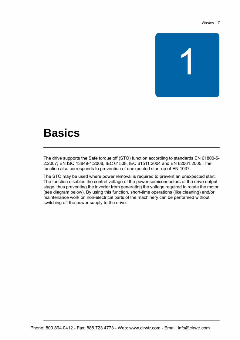
The drive supports the Safe torque off (STO) function according to standards EN 61800-5-2:2007; EN ISO 13849-1:2008, IEC 61508, IEC 61511:2004 and EN 62061:2005. The function also corresponds to prevention of unexpected start-up of EN 1037.
The STO may be used where power removal is required to prevent an unexpected start. The function disables the control voltage of the power semiconductors of the drive output stage, thus preventing the inverter from generating the voltage required to rotate the motor (see diagram below). By using this function, short-time operations (like cleaning) and/or maintenance work on non-electrical parts of the machinery can be performed without switching off the power supply to the drive.
Phone: 800.894.0412 - Fax: 888.723.4773 - Web: www.clrwtr.com - Email: [email protected]
8 Basics
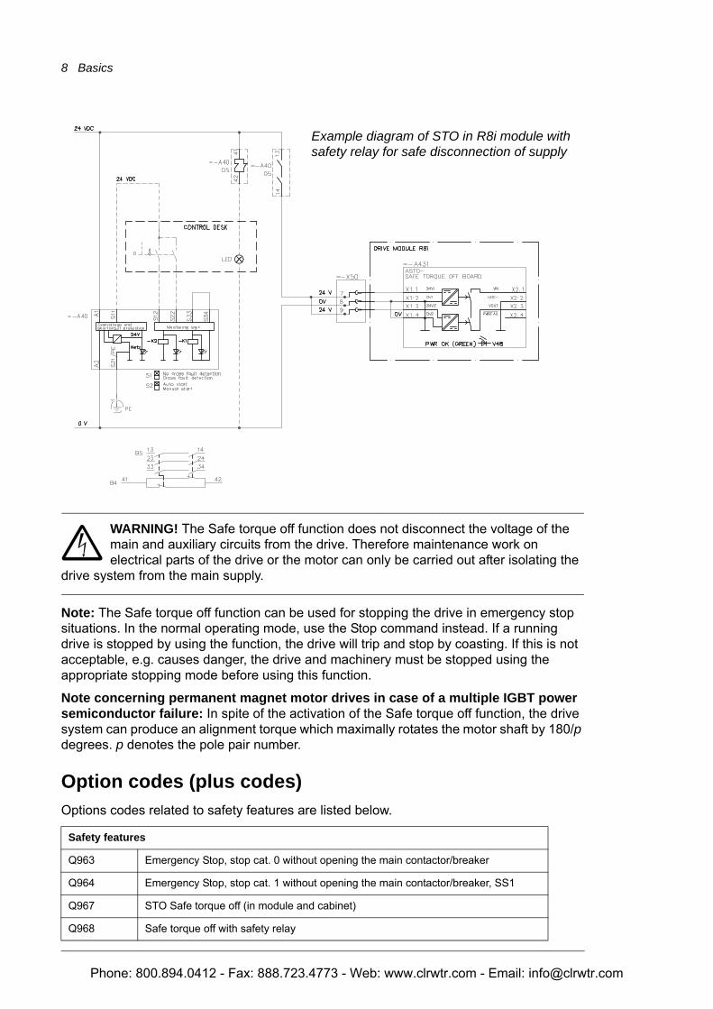
WARNING! The Safe torque off function does not disconnect the voltage of the main and auxiliary circuits from the drive. Therefore maintenance work on electrical parts of the drive or the motor can only be carried out after isolating the
drive system from the main supply.
Note: The Safe torque off function can be used for stopping the drive in emergency stop situations. In the normal operating mode, use the Stop command instead. If a running drive is stopped by using the function, the drive will trip and stop by coasting. If this is not acceptable, e.g. causes danger, the drive and machinery must be stopped using the appropriate stopping mode before using this function.
Note concerning permanent magnet motor drives in case of a multiple IGBT power semiconductor failure: In spite of the activation of the Safe torque off function, the drive system can produce an alignment torque which maximally rotates the motor shaft by 180/p degrees. p denotes the pole pair number.
Option codes (plus codes)Options codes related to safety features are listed below.
Safety features
Q963 Emergency Stop, stop cat. 0 without opening the main contactor/breaker
Q964 Emergency Stop, stop cat. 1 without opening the main contactor/breaker, SS1
Q967 STO Safe torque off (in module and cabinet)
Q968 Safe torque off with safety relay
Example diagram of STO in R8i module with safety relay for safe disconnection of supply
Phone: 800.894.0412 - Fax: 888.723.4773 - Web: www.clrwtr.com - Email: [email protected]
Program features, settings and diagnostics 9
2
Program features, settings and diagnostics
Operation of the STO function and its diagnostics functionWhen both STO inputs are energized, the STO function is in the standby state and the drive operates normally. If the STO inputs are de-energized, the STO function awakes, stops the drive and disables start. Start is possible only after the STO inputs have been energized, and any faults of the drive have been reset.
The table below describes the operation of the STO function in detail depending on:• status of the STO inputs• the fault or warning START INHIBI (see chapter Maintenance and fault tracing).
Status of STO inputs When drive is How the STO function operates START INHIBI indication
De-energizedrunning Awakes and trips the drive. Fault
stopped Awakes and disables start. Warning
One energized, other de-energized
running Awakes and trips the drive. Fault
stopped Awakes and disables start. Warning
Energized running or stopped STO is on standby. Drive operates normally. -
Phone: 800.894.0412 - Fax: 888.723.4773 - Web: www.clrwtr.com - Email: [email protected]
10 Program features, settings and diagnostics
STO status indications
See also chapter Maintenance and fault tracing.
STO function activation and indication delaysModule delays only
1) STO activation delay = delay between de-energizing the STO input and switching off the drive output bridge2) STO indication delay = delay between de-energizing the STO input and indication of STO input de-energization
Delays with typical STO safety relay
3) STO activation delay = delay between de-energizing the STO relay and switching off the drive output bridge4) STO indication delay = delay between de-energizing the STO relay and indication of STO input de-energization
Control program Alarm and status bits / words
System Control Program 08.02 AUX STATUS WORD bit 808.21 START INHIBI WORD
Standard Control Program 03.03 AUX STATUS WORD bit 8
Control program Alarms and faults
System Control Program 09.04 ALARM WORD 1 bit 009.06 FAULT WORD 3 bit 531.02 START INHIBIT ALM
Standard Control Program 03.08 ALARM WORD 1 bit 0
Control program Digital / relay outputs
System Control Program 14 DIGITAL OUTPUTSNote: To be programmed by the user. For information on programming the digital outputs, see ACS800 system control program firmware manual [3AFE64670646 (English)].
Standard Control Program 14 RELAY OUTPUTSNote: To be programmed by the user. For information on programming the relay outputs, see ACS800 standard control program firmware manual [3AFE64527592 (English)].
STO activation and indication delays Typical delay Maximum delay
STO activation delay 1) 2 ms 20 ms
STO indication delay 2) 1.5 ms -
STO activation and indication delays Typical delay Maximum delay
STO activation delay 3) 52 ms 70 ms
STO indication delay 4) 51.5 ms -
Phone: 800.894.0412 - Fax: 888.723.4773 - Web: www.clrwtr.com - Email: [email protected]
Installation 11
3
Installation
WARNING! The supply voltage for ASTO-11C and ASTO-21C board is 24 V DC. If the board is supplied with 230 V or 115 V, the board is damaged and it needs to be replaced.
Note: Since former option +Q950 (Prevention of unexpected start-up function) uses 230 V or 115 V supply voltage, it is not possible to use it with Safe torque off function (option +Q967) or vice versa. Note this when using spare parts. Note also that Safe torque off function can not be installed to drive module afterwards (ie, after the factory assembly) due to safety lifecycle requirements.
Example wiring diagrams
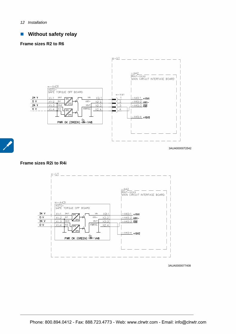
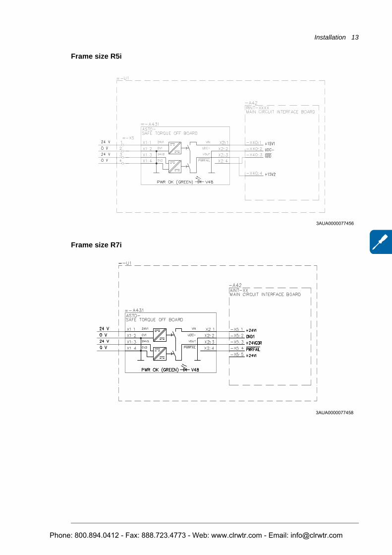
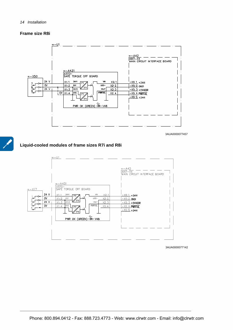
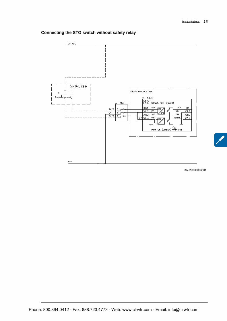
WARNING! For connecting the ASTO board and the module, use only wire kits delivered by ABB.
Connect the cables as shown in the diagram below. For more information on the components, see chapter Technical data.
Phone: 800.894.0412 - Fax: 888.723.4773 - Web: www.clrwtr.com - Email: [email protected]
12 Installation
Without safety relay
Frame sizes R2 to R6
Frame sizes R2i to R4i
3AUA0000072542
3AUA0000077408
Phone: 800.894.0412 - Fax: 888.723.4773 - Web: www.clrwtr.com - Email: [email protected]
Installation 13
Frame size R5i
Frame size R7i
3AUA0000077456
3AUA0000077458
Phone: 800.894.0412 - Fax: 888.723.4773 - Web: www.clrwtr.com - Email: [email protected]
14 Installation
Frame size R8i
Liquid-cooled modules of frame sizes R7i and R8i
3AUA0000077457
3AUA0000077142
Phone: 800.894.0412 - Fax: 888.723.4773 - Web: www.clrwtr.com - Email: [email protected]
Installation 15
Connecting the STO switch without safety relay
3AUA0000096631
Phone: 800.894.0412 - Fax: 888.723.4773 - Web: www.clrwtr.com - Email: [email protected]
16 Installation
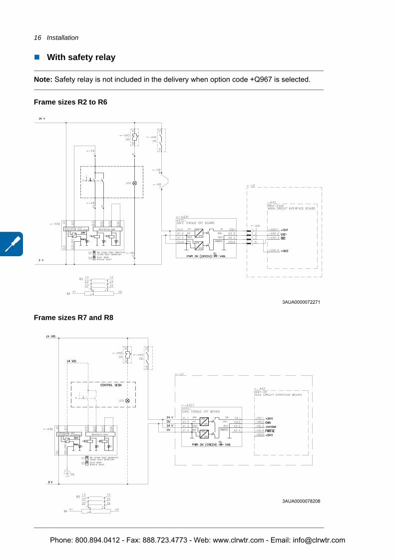
With safety relay
Note: Safety relay is not included in the delivery when option code +Q967 is selected.
Frame sizes R2 to R6
Frame sizes R7 and R8
3AUA0000072271
3AUA0000078208
Phone: 800.894.0412 - Fax: 888.723.4773 - Web: www.clrwtr.com - Email: [email protected]
Installation 17
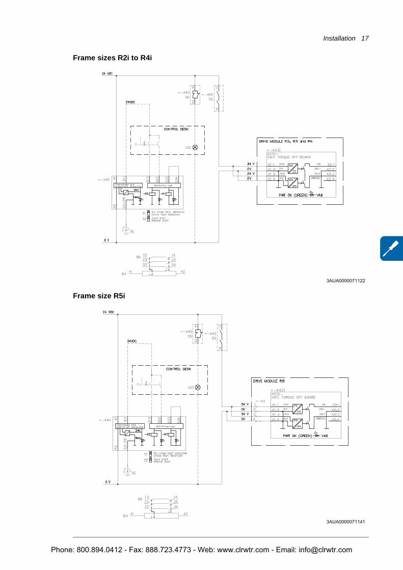
Frame sizes R2i to R4i
Frame size R5i
3AUA0000071122
3AUA0000071141
Phone: 800.894.0412 - Fax: 888.723.4773 - Web: www.clrwtr.com - Email: [email protected]
18 Installation
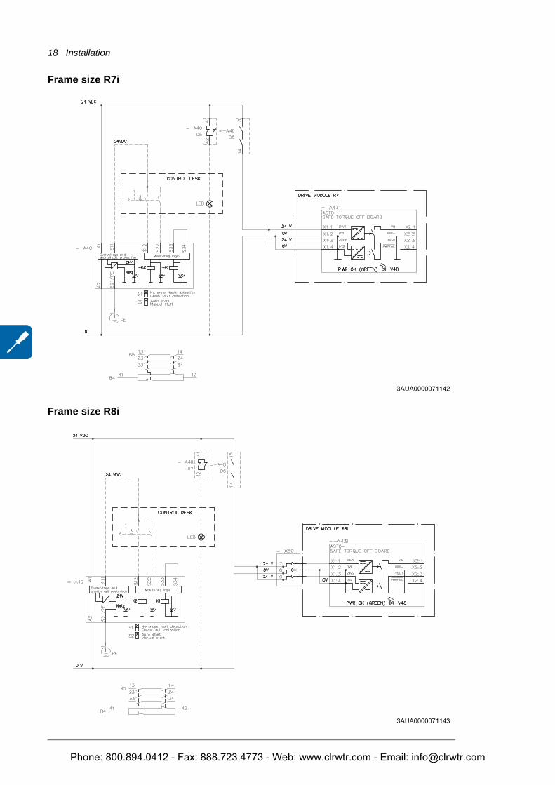
Frame size R7i
Frame size R8i
3AUA0000071142
3AUA0000071143
Phone: 800.894.0412 - Fax: 888.723.4773 - Web: www.clrwtr.com - Email: [email protected]
Installation 19
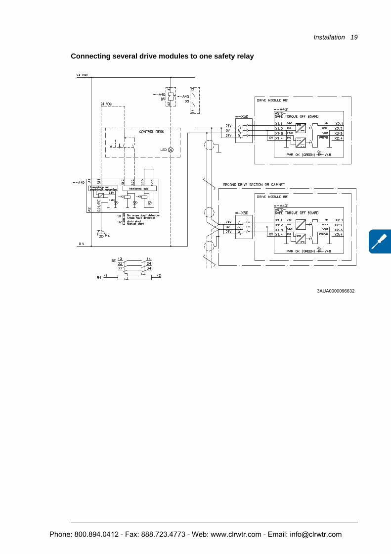
Connecting several drive modules to one safety relay
3AUA0000096632
Phone: 800.894.0412 - Fax: 888.723.4773 - Web: www.clrwtr.com - Email: [email protected]
20 Installation
Phone: 800.894.0412 - Fax: 888.723.4773 - Web: www.clrwtr.com - Email: [email protected]
Start-up and validation 21
4
Start-up and validation
Validating the operation of a safety functionEN IEC 62061 and EN ISO 13849 require that the final assembler of the machine validates the operation of the safety function with an acceptance test. The acceptance tests for the standard safety functions of the drive are described in chapter Start-up of the drive Hardware (or User's) manual. The tests for the optional safety functions are described in the appropriate option manuals.
The acceptance test must be performed:• at initial start-up of the safety function• after any changes related to the safety function (wiring, components, settings, etc.)• after any changes related to the circuit boards of the drive• after any maintenance work related to the safety function.
Authorized personThe acceptance test of the safety function must be carried out by an authorized person with expertise and knowledge of the safety function. The test must be documented and signed by the authorized person.
Acceptance test reportsSigned acceptance test reports must be stored in the logbook of the machine. The report shall include documentation of start-up activities and test results, references to failure reports and resolution of failures. Any new acceptance tests performed due to changes or maintenance shall be logged into the logbook.
Phone: 800.894.0412 - Fax: 888.723.4773 - Web: www.clrwtr.com - Email: [email protected]
22 Start-up and validation
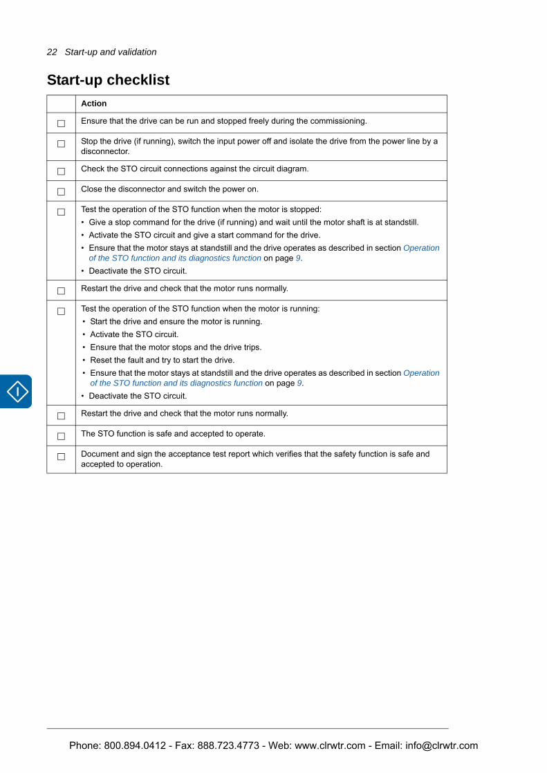
Start-up checklistAction
Ensure that the drive can be run and stopped freely during the commissioning.
Stop the drive (if running), switch the input power off and isolate the drive from the power line by a disconnector.
Check the STO circuit connections against the circuit diagram.
Close the disconnector and switch the power on.
Test the operation of the STO function when the motor is stopped: • Give a stop command for the drive (if running) and wait until the motor shaft is at standstill. • Activate the STO circuit and give a start command for the drive.• Ensure that the motor stays at standstill and the drive operates as described in section Operation
of the STO function and its diagnostics function on page 9.• Deactivate the STO circuit.
Restart the drive and check that the motor runs normally.
Test the operation of the STO function when the motor is running: • Start the drive and ensure the motor is running.• Activate the STO circuit. • Ensure that the motor stops and the drive trips.• Reset the fault and try to start the drive.• Ensure that the motor stays at standstill and the drive operates as described in section Operation
of the STO function and its diagnostics function on page 9.• Deactivate the STO circuit.
Restart the drive and check that the motor runs normally.
The STO function is safe and accepted to operate.
Document and sign the acceptance test report which verifies that the safety function is safe and accepted to operation.
Phone: 800.894.0412 - Fax: 888.723.4773 - Web: www.clrwtr.com - Email: [email protected]
Maintenance and fault tracing 23
5
Maintenance and fault tracing
MaintenanceInclude the STO operation test described in chapter Start-up and validation to the routine maintenance program of the machinery that the drive runs. If the circuit boards or wire sets are replaced inside the module, test the functioning of the safety circuit according to Start-up checklist. If you detect any failure in safety functions, including STO, contact your local ABB representative.
The STO function or STO input terminals do not need any maintenance. Maintain the drive according to the instructions given in the drive hardware manual.
Warning messages generated by the driveWarning Cause What to do
START INHIBI
Safe torque off function has been activated while the drive was stopped.
Close Safe torque off function switch. If the switch is closed and the warning is still active, check power supply at ASTO board input terminals. Replace ASTO board.
Phone: 800.894.0412 - Fax: 888.723.4773 - Web: www.clrwtr.com - Email: [email protected]
24 Maintenance and fault tracing
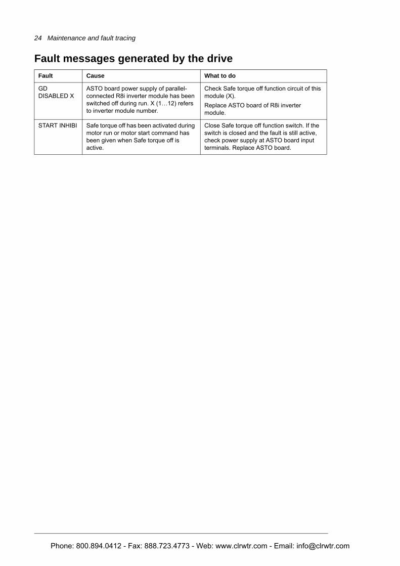
Fault messages generated by the driveFault Cause What to do
GD DISABLED X
ASTO board power supply of parallel-connected R8i inverter module has been switched off during run. X (1…12) refers to inverter module number.
Check Safe torque off function circuit of this module (X).Replace ASTO board of R8i inverter module.
START INHIBI Safe torque off has been activated during motor run or motor start command has been given when Safe torque off is active.
Close Safe torque off function switch. If the switch is closed and the fault is still active, check power supply at ASTO board input terminals. Replace ASTO board.
Phone: 800.894.0412 - Fax: 888.723.4773 - Web: www.clrwtr.com - Email: [email protected]
Technical data 25
6
Technical data
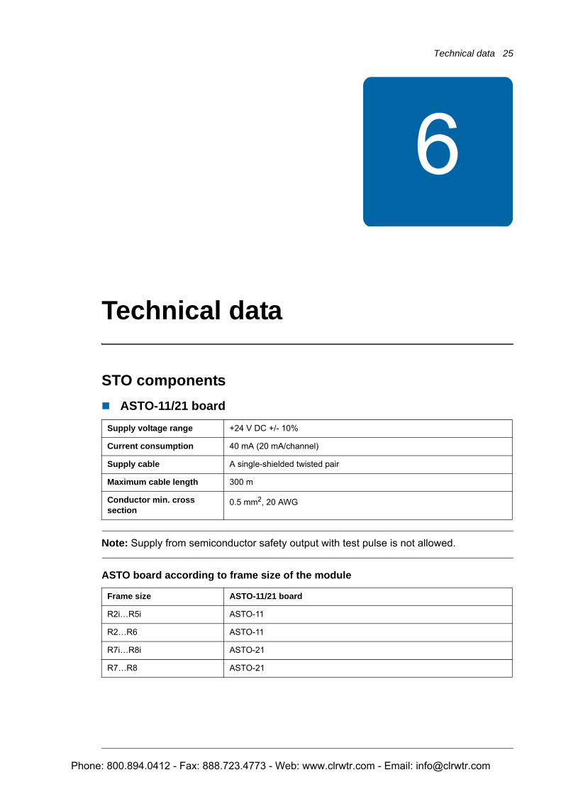
STO componentsASTO-11/21 board
Note: Supply from semiconductor safety output with test pulse is not allowed.
ASTO board according to frame size of the module
Supply voltage range +24 V DC +/- 10%
Current consumption 40 mA (20 mA/channel)
Supply cable A single-shielded twisted pair
Maximum cable length 300 m
Conductor min. cross section
0.5 mm2, 20 AWG
Frame size ASTO-11/21 board
R2i…R5i ASTO-11
R2…R6 ASTO-11
R7i…R8i ASTO-21
R7…R8 ASTO-21
Phone: 800.894.0412 - Fax: 888.723.4773 - Web: www.clrwtr.com - Email: [email protected]
26 Technical data
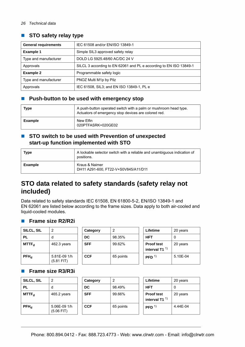
STO safety relay type
Push-button to be used with emergency stop
STO switch to be used with Prevention of unexpectedstart-up function implemented with STO
STO data related to safety standards (safety relay not included)Data related to safety standards IEC 61508, EN 61800-5-2, EN/ISO 13849-1 and EN 62061 are listed below according to the frame sizes. Data apply to both air-cooled and liquid-cooled modules.
Frame size R2/R2i
Frame size R3/R3i
General requirements IEC 61508 and/or EN/ISO 13849-1
Example 1 Simple SIL3 approved safety relay
Type and manufacturer DOLD LG 5925.48/60 AC/DC 24 V
Approvals SILCL 3 according to EN 62061 and PL e according to EN ISO 13849-1
Example 2 Programmable safety logic
Type and manufacturer PNOZ Multi M1p by Pilz
Approvals IEC 61508, SIL3; and EN ISO 13849-1, PL e
Type A push-button operated switch with a palm or mushroom head type. Actuators of emergency stop devices are colored red.
Example New Elfin020PTFASRK+020GE02
Type A lockable selector switch with a reliable and unambiguous indication of positions.
Example Kraus & NaimerDH11 A291-600, FT22-V+S0V845/A11/D11
SILCL, SIL 2 Category 2 Lifetime 20 years
PL d DC 98.35% HFT 0
MTTFd 462.3 years SFF 99.62% Proof test interval T1 1)
20 years
PFHd 5.81E-09 1/h (5.81 FIT)
CCF 65 points PFD 1) 5.10E-04
SILCL, SIL 2 Category 2 Lifetime 20 years
PL d DC 98.49% HFT 0
MTTFd 465.2 years SFF 99.66% Proof test interval T1 1)
20 years
PFHd 5.06E-09 1/h(5.06 FIT)
CCF 65 points PFD 1) 4.44E-04
Phone: 800.894.0412 - Fax: 888.723.4773 - Web: www.clrwtr.com - Email: [email protected]
Technical data 27
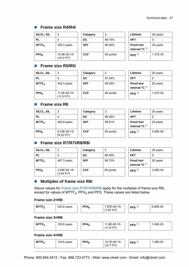
Frame size R4/R4i
Frame size R5/R5i
Frame size R6
Frame size R7/R7i/R8/R8i
Multiples of frame size R8iAbove values for Frame size R7/R7i/R8/R8i apply for the multiples of frame size R8i, except for values of MTTFd, PFHd and PFD. These values are listed below.
Frame size 2×R8i
Frame size 3×R8i
Frame size 4×R8i
SILCL, SIL 2 Category 2 Lifetime 20 years
PL d DC 96.74% HFT 0
MTTFd 430.4 years SFF 99.26% Proof test interval T1 1)
20 years
PFHd 15.0E-09 1/h(15.0 FIT)
CCF 65 points PFD 1) 1.31E-03
SILCL, SIL 2 Category 2 Lifetime 20 years
PL d DC 97.34% HFT 0
MTTFd 442.0 years SFF 99.39% Proof test interval T1 1)
20 years
PFHd 11.5E-09 1/h(11.5 FIT)
CCF 65 points PFD 1) 1.01E-03
SILCL, SIL 2 Category 2 Lifetime 20 years
PL d DC 98.28% HFT 0
MTTFd 460.8 years SFF 99.61% Proof test interval T1 1)
20 years
PFHd 6.23E-09 1/h(6.23 FIT)
CCF 65 points PFD 1) 5.46E-04
SILCL, SIL 2 Category 2 Lifetime 20 years
PL d DC 98.40% HFT 0
MTTFd 467.3 years SFF 99.72% Proof test interval T1 1)
20 years
PFHd 3.94E-09 1/h(3.94 FIT)
CCF 65 points PFD 1) 3.45E-04
MTTFd 233.6 years PFHd 7.87E-09 1/h (7.87 FIT)
PFD 1) 6.90E-04
MTTFd 155.8 years PFHd 11.8E-09 1/h (11.8 FIT)
PFD 1) 1.04E-03
MTTFd 116.8 years PFHd 15.7E-09 1/h (15.7 FIT)
PFD 1) 1.38E-03
Phone: 800.894.0412 - Fax: 888.723.4773 - Web: www.clrwtr.com - Email: [email protected]
28 Technical data
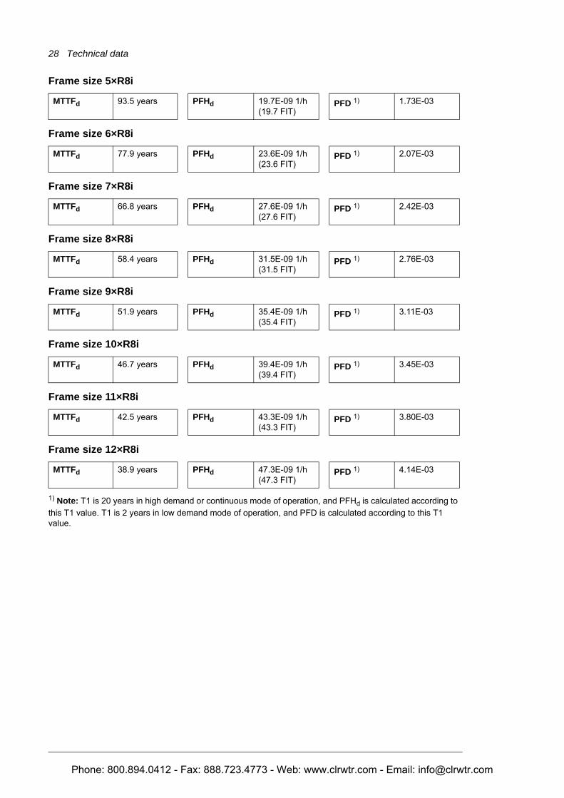
Frame size 5×R8i
Frame size 6×R8i
Frame size 7×R8i
Frame size 8×R8i
Frame size 9×R8i
Frame size 10×R8i
Frame size 11×R8i
Frame size 12×R8i
1) Note: T1 is 20 years in high demand or continuous mode of operation, and PFHd is calculated according to this T1 value. T1 is 2 years in low demand mode of operation, and PFD is calculated according to this T1 value.
MTTFd 93.5 years PFHd 19.7E-09 1/h (19.7 FIT)
PFD 1) 1.73E-03
MTTFd 77.9 years PFHd 23.6E-09 1/h (23.6 FIT)
PFD 1) 2.07E-03
MTTFd 66.8 years PFHd 27.6E-09 1/h (27.6 FIT)
PFD 1) 2.42E-03
MTTFd 58.4 years PFHd 31.5E-09 1/h (31.5 FIT)
PFD 1) 2.76E-03
MTTFd 51.9 years PFHd 35.4E-09 1/h (35.4 FIT)
PFD 1) 3.11E-03
MTTFd 46.7 years PFHd 39.4E-09 1/h (39.4 FIT)
PFD 1) 3.45E-03
MTTFd 42.5 years PFHd 43.3E-09 1/h (43.3 FIT)
PFD 1) 3.80E-03
MTTFd 38.9 years PFHd 47.3E-09 1/h (47.3 FIT)
PFD 1) 4.14E-03
Phone: 800.894.0412 - Fax: 888.723.4773 - Web: www.clrwtr.com - Email: [email protected]
Technical data 29
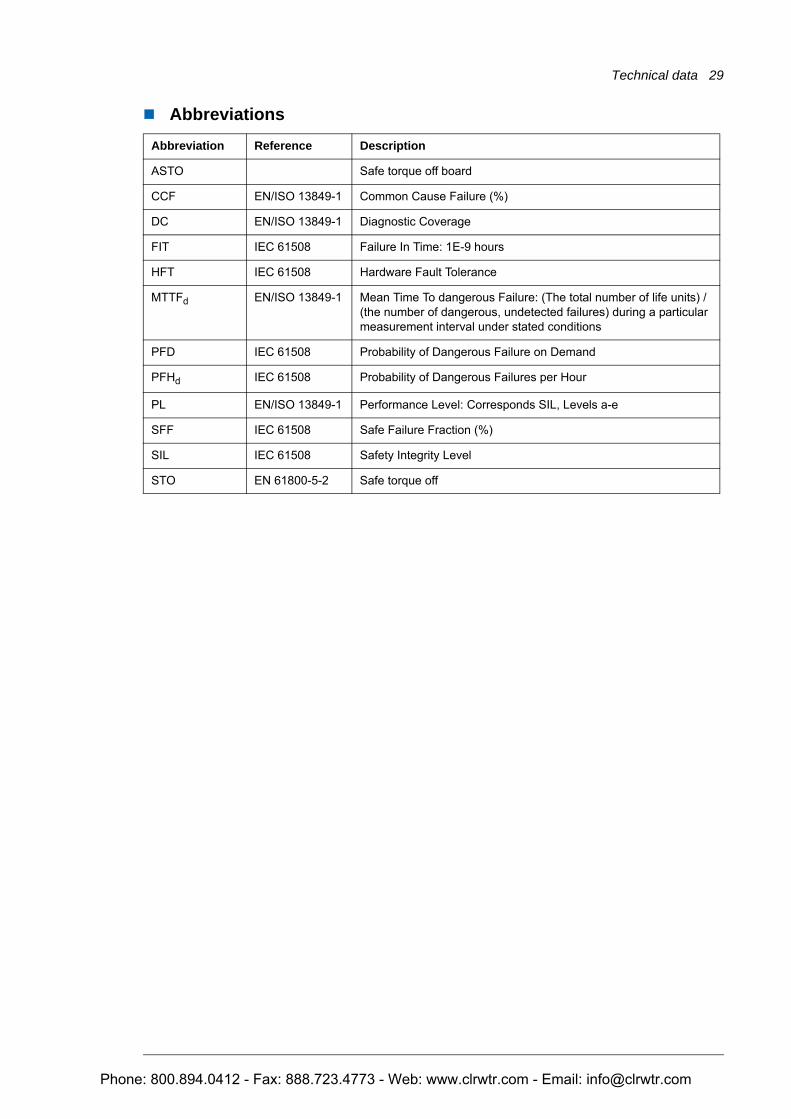
AbbreviationsAbbreviation Reference Description
ASTO Safe torque off board
CCF EN/ISO 13849-1 Common Cause Failure (%)
DC EN/ISO 13849-1 Diagnostic Coverage
FIT IEC 61508 Failure In Time: 1E-9 hours
HFT IEC 61508 Hardware Fault Tolerance
MTTFd EN/ISO 13849-1 Mean Time To dangerous Failure: (The total number of life units) / (the number of dangerous, undetected failures) during a particular measurement interval under stated conditions
PFD IEC 61508 Probability of Dangerous Failure on Demand
PFHd IEC 61508 Probability of Dangerous Failures per Hour
PL EN/ISO 13849-1 Performance Level: Corresponds SIL, Levels a-e
SFF IEC 61508 Safe Failure Fraction (%)
SIL IEC 61508 Safety Integrity Level
STO EN 61800-5-2 Safe torque off
Phone: 800.894.0412 - Fax: 888.723.4773 - Web: www.clrwtr.com - Email: [email protected]
30 Technical data
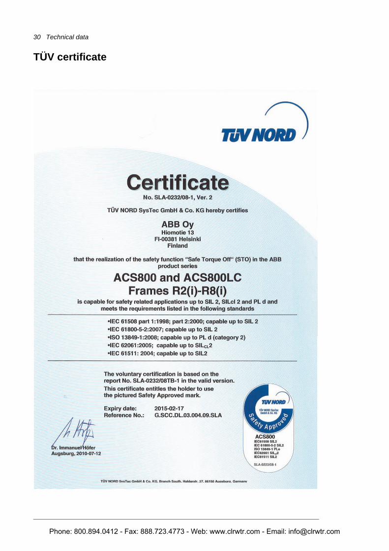
TÜV certificate
Phone: 800.894.0412 - Fax: 888.723.4773 - Web: www.clrwtr.com - Email: [email protected]


![ABB ACS800-01/04/11/31/104/104LC Safe Torque Off ......2011/01/04 · firmware manual [3AFE64670646 (English)]. Standard Control Program 14 RELAY OUTPUTS Note: To be programmed by](https://img.pdfslide.net/doc/110x75/6085b96276d34668025ffefb/abb-acs800-01041131104104lc-safe-torque-off-20110104-firmware.jpg)