Embed Size (px)
Citation preview
—ABB DRIVES
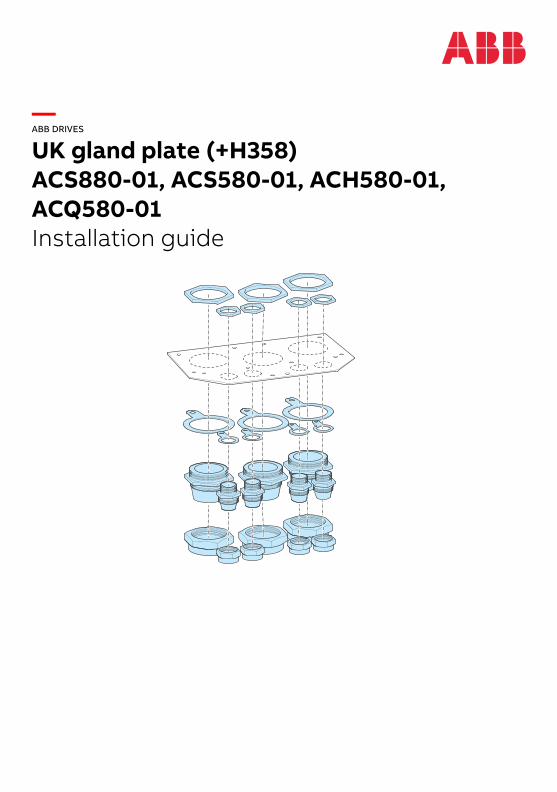
UK gland plate (+H358)ACS880-01, ACS580-01, ACH580-01, ACQ580-01Installation guide

—
Installation guide
UK gland plate (+H358)ACS880-01, ACS580-01, ACH580-01, ACQ580-01
3AXD50000034735 Rev BEN
EFFECTIVE: 2018-11-21
2018 ABB Oy. All Rights Reserved.
Table of contents

Table of contents 1
Table of contents
Installation with option +H358 UK gland plate
Safety instructions . . . . . . . . . . . . . . . . . . . . . . . . . . . . . . . . . . . . . . . . . . . . . . . . . . . . . . . . . . . 3Introduction to the guide . . . . . . . . . . . . . . . . . . . . . . . . . . . . . . . . . . . . . . . . . . . . . . . . . . . . . . 3
Applicability . . . . . . . . . . . . . . . . . . . . . . . . . . . . . . . . . . . . . . . . . . . . . . . . . . . . . . . . . . . . . 3Target audience . . . . . . . . . . . . . . . . . . . . . . . . . . . . . . . . . . . . . . . . . . . . . . . . . . . . . . . . . 3Contents of the guide . . . . . . . . . . . . . . . . . . . . . . . . . . . . . . . . . . . . . . . . . . . . . . . . . . . . . 3
Related manuals . . . . . . . . . . . . . . . . . . . . . . . . . . . . . . . . . . . . . . . . . . . . . . . . . . . . . . . . . . . . 4Abbreviations . . . . . . . . . . . . . . . . . . . . . . . . . . . . . . . . . . . . . . . . . . . . . . . . . . . . . . . . . . . 4
Removing the rubber grommets . . . . . . . . . . . . . . . . . . . . . . . . . . . . . . . . . . . . . . . . . . . . . . . . 4Frames R4 and R5: Removing the power clamp shelf and EMC shroud . . . . . . . . . . . . . . . . . 5Frames R6 to R9: Removing the standard bottom plate and power cable clamp shelf from the cable box . . . . . . . . . . . . . . . . . . . . . . . . . . . . . . . . . . . . . . . . . . . . . . . . . . . . . . . . . . . . . . . . . . 6Making holes into the UK gland plate . . . . . . . . . . . . . . . . . . . . . . . . . . . . . . . . . . . . . . . . . . . . 7Installing the SWA glands . . . . . . . . . . . . . . . . . . . . . . . . . . . . . . . . . . . . . . . . . . . . . . . . . . . . . 9
SWA gland kit parts . . . . . . . . . . . . . . . . . . . . . . . . . . . . . . . . . . . . . . . . . . . . . . . . . . . . . . . 9Needed tools . . . . . . . . . . . . . . . . . . . . . . . . . . . . . . . . . . . . . . . . . . . . . . . . . . . . . . . . . . . . 9Installing the SWA gland over a power cable . . . . . . . . . . . . . . . . . . . . . . . . . . . . . . . . . . 10Installing the SWA gland over a control cable . . . . . . . . . . . . . . . . . . . . . . . . . . . . . . . . . . 15
Attaching the UK gland plate to the drive – Frames R1 to R5 . . . . . . . . . . . . . . . . . . . . . . . . . 16Attaching the UK gland plate to the drive – Frames R6 to R9 . . . . . . . . . . . . . . . . . . . . . . . . . 18Installing the drive on wall – Frames R1 to R4 . . . . . . . . . . . . . . . . . . . . . . . . . . . . . . . . . . . . 18Installing the drive on wall – Frames R5 to R9 . . . . . . . . . . . . . . . . . . . . . . . . . . . . . . . . . . . . 19Connecting the power cables . . . . . . . . . . . . . . . . . . . . . . . . . . . . . . . . . . . . . . . . . . . . . . . . . 22

2 Table of contents
Installation with option +H358 UK gland plate 3
Installation with option +H358 UK gland plate
Safety instructions
Obey all safety instructions of the drive. Read the safety instructions before you install, start up, or use the drive. See the hardware manual.
Introduction to the guide
Applicability
This guide is applicable to the following drives with option +H358 UK gland plate and degree of protection of IP21:
• ACS880-01
• ACH580-01, ACQ580-01, ACS580-01.
The guide is a supplement to the hardware manual.
Target audience
This supplement is intended for people who plan the installation, install, start up, use and service the drive. Read the supplement before you do work on the drive. You are expected to know the fundamentals of electricity, wiring, electrical components and electrical schematic symbols.
Contents of the guide
This guide contains installation instructions on how to
• remove the standard bottom plate and power cable shelf from the drive
• install SWA glands over the power and control cables
• install SWA glands to the UK gland plate
• install the UK gland plate to the drive
• connect the power cables to the drive.
For other instructions, see the drive hardware manual.
4 Installation with option +H358 UK gland plate
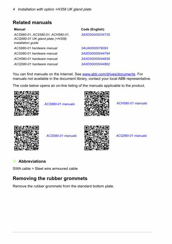
Related manuals
You can find manuals on the Internet. See www.abb.com/drives/documents. For manuals not available in the document library, contact your local ABB representative.
The code below opens an on-line listing of the manuals applicable to the product.
Abbreviations
SWA cable = Steel wire armoured cable
Removing the rubber grommets
Remove the rubber grommets from the standard bottom plate.
Manual Code (English)
ACS880-01, ACS580-01, ACH580-01, ACQ580-01 UK gland plate (+H358) installation guide
3AXD50000034735
ACS880-01 hardware manual 3AUA0000078093
ACS580-01 hardware manual 3AXD50000044794
ACH580-01 hardware manual 3AXD50000044839
ACQ580-01 hardware manual 3AXD50000044862
ACS880-01 manuals
ACS580-01 manuals
ACH580-01 manuals
ACQ580-01 manuals
Installation with option +H358 UK gland plate 5
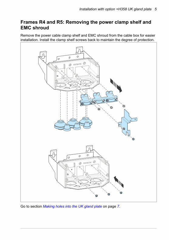
Frames R4 and R5: Removing the power clamp shelf and EMC shroud
Remove the power cable clamp shelf and EMC shroud from the cable box for easier installation. Install the clamp shelf screws back to maintain the degree of protection.
Go to section Making holes into the UK gland plate on page 7.
6 Installation with option +H358 UK gland plate
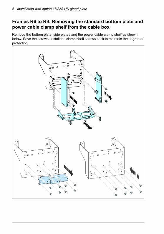
Frames R6 to R9: Removing the standard bottom plate and power cable clamp shelf from the cable box
Remove the bottom plate, side plates and the power cable clamp shelf as shown below. Save the screws. Install the clamp shelf screws back to maintain the degree of protection.
Installation with option +H358 UK gland plate 7
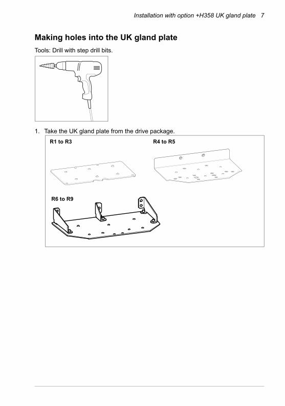
Making holes into the UK gland plate
Tools: Drill with step drill bits.
1. Take the UK gland plate from the drive package.
R1 to R3 R4 to R5
R6 to R9
8 Installation with option +H358 UK gland plate
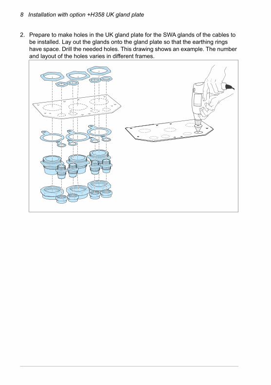
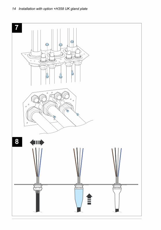
2. Prepare to make holes in the UK gland plate for the SWA glands of the cables to be installed. Lay out the glands onto the gland plate so that the earthing rings have space. Drill the needed holes. This drawing shows an example. The number and layout of the holes varies in different frames.
Installation with option +H358 UK gland plate 9
Installing the SWA glands
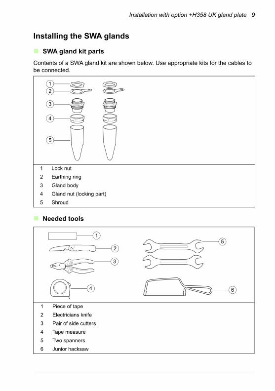
SWA gland kit parts
Contents of a SWA gland kit are shown below. Use appropriate kits for the cables to be connected.
Needed tools
1 Lock nut
2 Earthing ring
3 Gland body
4 Gland nut (locking part)
5 Shroud
1 Piece of tape
2 Electricians knife
3 Pair of side cutters
4 Tape measure
5 Two spanners
6 Junior hacksaw
5
3
4
1
2
1
4
2
3
5
6
10 Installation with option +H358 UK gland plate
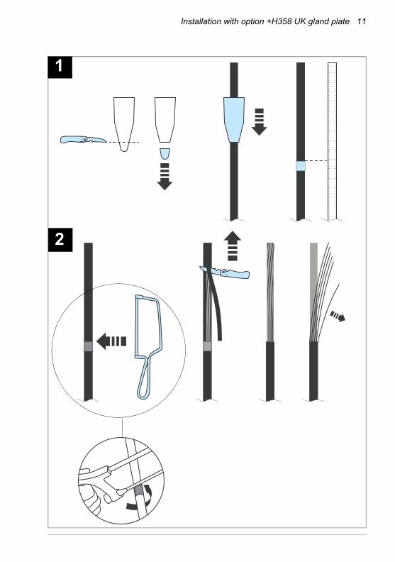
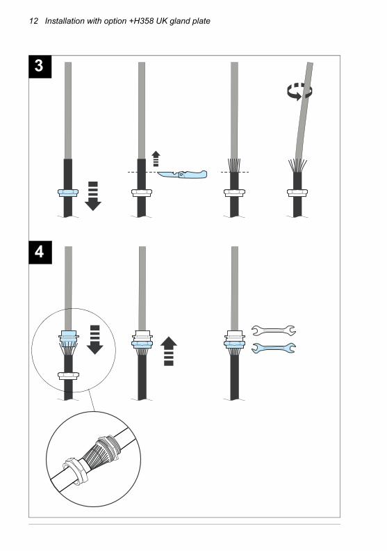
Installing the SWA gland over a power cable
See the drawings on the next pages.
1. Cut the shroud to fit the cable. Slide it over the cable. Measure the cable length that is required inside the drive. Mark the measured point with tape.
2. Cut the outer sheath around the cable at the tape halfway through the steel wire armour with junior hacksaw. Peel off the sheath with electricians knife. Pick three to four steel wires at a time and bend them back and forth to break and remove them.
3. Slide the gland nut over the cable. Cut off 25 mm of the sheath with electricians knife. Rotate the cable by hand to bend the steel wires so that the cone end of the gland body will fit under.
4. - Slide the gland body under the steel wires. Make sure that the wires do not go over the cone end of the gland body, or that they are long enough for the electric bonding. - Slide the gland nut onto the cone end of the gland body and hand tighten it. Hold the gland body with a spanner and tighten the nut with the other spanner.
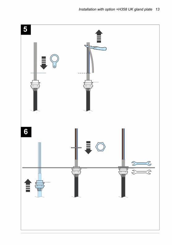
5. Put the earthing ring onto the gland body. Carefully, so as not to cut into the conductors, cut the bedding with electricians knife and peel it off.
6. Put the cable through the hole in the gland plate. Slide the lock nut over the cable onto the gland body. Hold the gland body with a spanner and tighten the lock nut with the other spanner.
7. Attach the earthing ring to the gland plate with a screw and nut.
8. Fit the shroud over the gland.
Installation with option +H358 UK gland plate 11
1
2
12 Installation with option +H358 UK gland plate
3
4
Installation with option +H358 UK gland plate 13
5
6
14 Installation with option +H358 UK gland plate
7
8
Installation with option +H358 UK gland plate 15
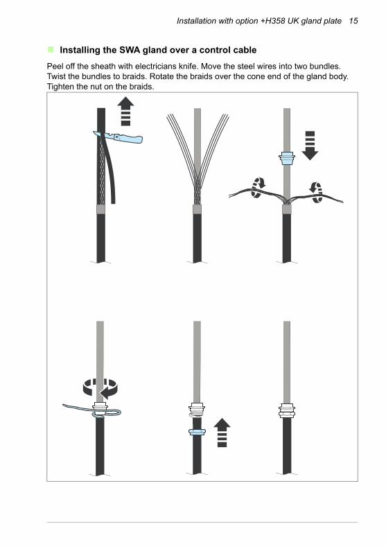
Installing the SWA gland over a control cable
Peel off the sheath with electricians knife. Move the steel wires into two bundles. Twist the bundles to braids. Rotate the braids over the cone end of the gland body. Tighten the nut on the braids.
16 Installation with option +H358 UK gland plate
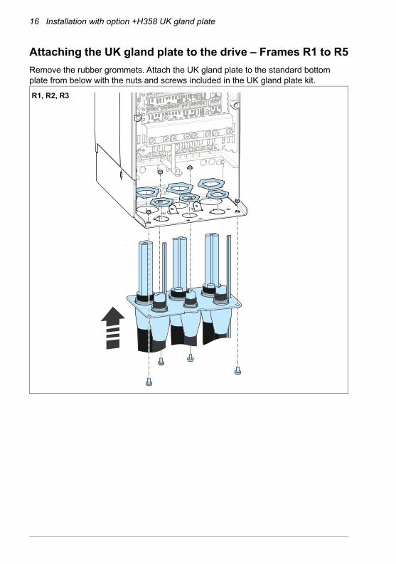
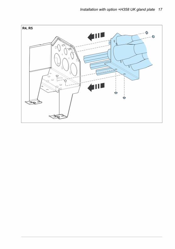
Attaching the UK gland plate to the drive – Frames R1 to R5
Remove the rubber grommets. Attach the UK gland plate to the standard bottom plate from below with the nuts and screws included in the UK gland plate kit.
R1, R2, R3
Installation with option +H358 UK gland plate 17
R4, R5
18 Installation with option +H358 UK gland plate
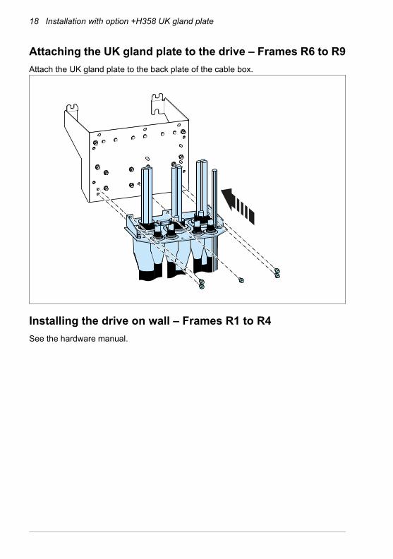
Attaching the UK gland plate to the drive – Frames R6 to R9
Attach the UK gland plate to the back plate of the cable box.
Installing the drive on wall – Frames R1 to R4
See the hardware manual.
Installation with option +H358 UK gland plate 19
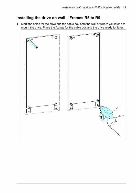
Installing the drive on wall – Frames R5 to R9
1. Mark the holes for the drive and the cable box onto the wall or where you intend to mount the drive. Place the fixings for the cable box and the drive ready for later.
20 Installation with option +H358 UK gland plate
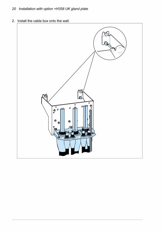
2. Install the cable box onto the wall.
Installation with option +H358 UK gland plate 21
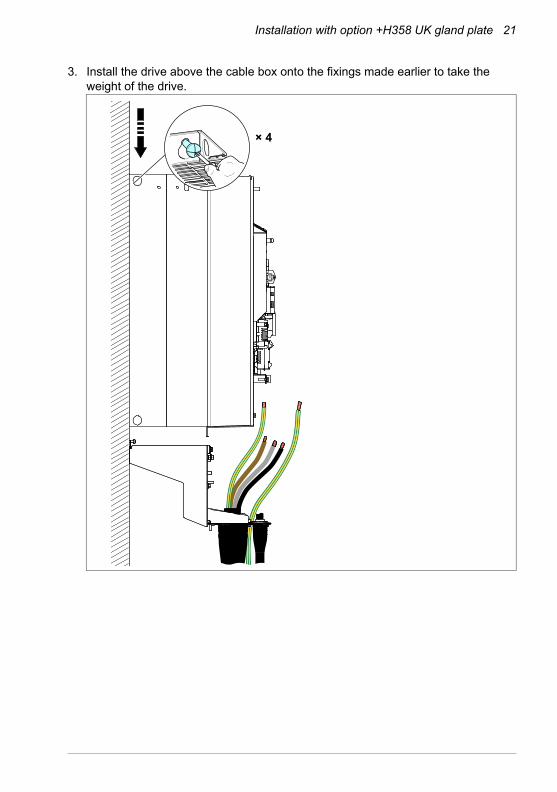
3. Install the drive above the cable box onto the fixings made earlier to take the weight of the drive.
× 4
22 Installation with option +H358 UK gland plate
Connecting the power cables
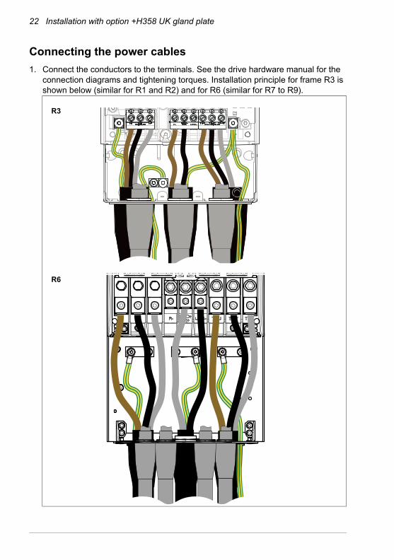
1. Connect the conductors to the terminals. See the drive hardware manual for the connection diagrams and tightening torques. Installation principle for frame R3 is shown below (similar for R1 and R2) and for R6 (similar for R7 to R9).
R6
R3
Installation with option +H358 UK gland plate 23
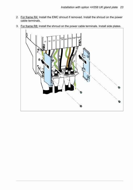
2. For frame R4: Install the EMC shroud if removed. Install the shroud on the power cable terminals.
3. For frame R8: Install the shroud on the power cable terminals. Install side plates.

24 Installation with option +H358 UK gland plate

—Further information
Product and service inquiriesAddress any inquiries about the product to your local ABB representative, quoting the type designation and serial number of the unit in question. A listing of ABB sales, support and service contacts can be found by navigating to abb.com/searchchannels.
Product trainingFor information on ABB product training, navigate to new.abb.com/service/training.
Providing feedback on ABB Drives manualsYour comments on our manuals are welcome. Navigate to new.abb.com/drives/manuals-feedback-form.
Document library on the InternetYou can find manuals and other product documents in PDF format on the Internet at abb.com/drives/documents.

abb.com/drives
© Copyright 2018 ABB. All rights reserved.Specifications subject to change without notice. 3A
XD
500
00
034
735
Rev
B (
EN
) 20
18-1
1-21