Embed Size (px)
Citation preview

ABB i-bus® KNX Meter Interface Module ZS/S 1.1 Product Manual


ABB i-bus KNX Contents
ZS/S 1.1 | 2CDC 512 066 D0203 i
Contents Page
1 General ................................................................................................. 3 1.1 Using the product manual .............................................................................................................4 1.1.1 Structure of the product manual ...................................................................................................4 1.1.2 Notes ............................................................................................................................................4 1.2 Product and functional overview ...................................................................................................5
2 Device technology ............................................................................... 7 2.1 Technical data ..............................................................................................................................7 2.2 Connection schematic ..................................................................................................................9 2.3 Dimensional drawing .................................................................................................................. 10 2.4 Assembly and installation ........................................................................................................... 11
3 Commissioning .................................................................................. 13 3.1 Application program .................................................................................................................... 13 3.1.1 Conversion ................................................................................................................................. 13 3.1.1.1 Procedure ................................................................................................................................... 14 3.2 Parameters ................................................................................................................................. 15 3.2.1 Parameter window General ........................................................................................................ 16 3.2.2 Parameter window Meter Reading ............................................................................................. 22 3.2.3 Parameter window Power Values ............................................................................................... 25 3.2.4 Parameter window Instrument Values ........................................................................................ 30 3.3 Communication objects .............................................................................................................. 35 3.3.1 Communication objects General ................................................................................................. 35 3.3.2 Communication objects Meter Reading ...................................................................................... 38 3.3.3 Communication objects Power Values ....................................................................................... 41 3.3.4 Communication objects Instrument Values................................................................................. 43 3.3.5 Communication objects Transformer Ratios ............................................................................... 45 3.3.6 Communication objects Resettable Energy Register .................................................................. 46
4 Planning and application .................................................................. 47 4.1 Energy meter overview ............................................................................................................... 47 4.1.1 A-series ...................................................................................................................................... 47 4.1.1.1 Function overview ....................................................................................................................... 48 4.1.2 DELTAplus ................................................................................................................................. 53 4.1.3 DELTAsingle ............................................................................................................................... 55 4.1.4 ODIN .......................................................................................................................................... 55 4.1.5 ODINsingle ................................................................................................................................. 55 4.2 Behavior after bus voltage recovery, download and ETS reset .................................................. 56 4.3 LED display ................................................................................................................................ 57
A Appendix ............................................................................................ 59 A.1 Status byte code table ................................................................................................................ 59 A.2 DELTAplus error codes .............................................................................................................. 60 A.3 DELTAsingle error codes............................................................................................................ 61 A.4 Energy measurement ................................................................................................................. 62 A.4.1 Measurement fundamentals ....................................................................................................... 62 A.4.2 Measurements with current and/or voltage transformers ............................................................ 64 A.4.3 Energy calculation ...................................................................................................................... 66 A.5 Ordering Information ................................................................................................................... 67

ABB i-bus KNX General
ZS/S 1.1 | 2CDC 512 066 D0203 3
1 General
Energy measurement The recording of energy variables and values as well as their processing is continually gaining in significance. This is not just due to the rising energy costs but also due to the frequently demanded evaluation and reading possibilities via a decentralized reading station. When combined with the features of the ABB i-bus®, the operator or user in the field of intelligent building technology can implement comfortable and economical solutions for modern energy management. The demands placed on recording and evaluation as well as on billing and charging in commercial and functional buildings, and also in industrial systems and residential properties has increased significantly over recent years. ABB offers a wide range of meters and interfaces specially designed for these applications.
What is Automatic Meter Reading (AMR)? Automatic Meter Reading (AMR) is the process of remote reading of data from meters. AMR allows the suppliers of electrical energy, as well as water, gas and district heating to improve the handling of their contracts and services. The ongoing costs involved in manual reading of the meter are eliminated and the consumption data become transparent.
What is energy management? Energy management is the overall concept which ranges from planning of requirement to selection, installation and operation of energy generation systems. The objective is to provide complete coverage of the energy needs of the consumer and to use the most minimum amount of energy at the given comfort or production levels (industrial and commercial). Energy management can be applied in every building where energy is required: industrial buildings, office buildings, sports halls, dwellings, apartments, etc.
Reasons for energy management:
• Guaranteeing the provision of an interruption free supply of energy or power
• Retention of the voltage or current quality
• Economic efficiency, e.g. favorable power or heat prices, conservation of energy
• Environmental aspects, e.g. conservation of energy, energy recovery
• Independence of fossil based primary energy carriers
What is load management? The primary objective of load management is an economical and resource efficient use of energy provided by electrical utility companies in industry, commercial applications and domestic households for environmental cost and/or safety reasons. Load management also incorporates measures for the avoidance of circuit overloads. Cost savings can be achieved by the avoidance of load peaks or reduction of consumption during tariff times when higher power prices are charged.
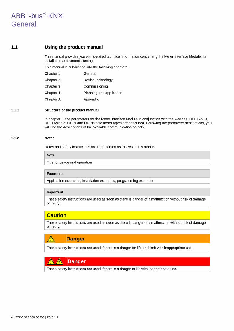
ABB i-bus KNX General
4 2CDC 512 066 D0203 | ZS/S 1.1
1.1 Using the product manual
This manual provides you with detailed technical information concerning the Meter Interface Module, its installation and commissioning.
This manual is subdivided into the following chapters:
Chapter 1 General
Chapter 2 Device technology
Chapter 3 Commissioning
Chapter 4 Planning and application
Chapter A Appendix
1.1.1 Structure of the product manual
In chapter 3, the parameters for the Meter Interface Module in conjunction with the A-series, DELTAplus, DELTAsingle, ODIN and ODINsingle meter types are described. Following the parameter descriptions, you will find the descriptions of the available communication objects.
1.1.2 Notes
Notes and safety instructions are represented as follows in this manual:
Note
Tips for usage and operation
Examples
Application examples, installation examples, programming examples
Important
These safety instructions are used as soon as there is danger of a malfunction without risk of damage or injury.
Caution These safety instructions are used as soon as there is danger of a malfunction without risk of damage or injury.
Danger These safety instructions are used if there is a danger for life and limb with inappropriate use.
Danger These safety instructions are used if there is a danger to life with inappropriate use.

ABB i-bus KNX General
ZS/S 1.1 | 2CDC 512 066 D0203 5
1.2 Product and functional overview
The Meter Interface Module ZS/S 1.1 from ABB STOTZ-KONTAKT converts telegrams from ABB energy meters for the DIN rail mounting into KNX telegrams. The device features an infrared interface, which can be used to read the data from ABB energy meter types A-series, DELTAplus, DELTAsingle, ODIN and ODINsingle. These read values can be processed in a number of ways, e.g. in visualization systems, energy management systems or for billing purposes. Different values and variables can be processed by the Meter Interface Module in dependence on the meter type used.
The following functions are available with the application program Meter data logging:
Functions of ZS/S 1.1 with A-series and DELTAplus meters* • Exported active and reactive energy (total, tariffs 1/2/3/4) • Active and reactive energy (total, tariffs 1/2/3/4) • Instantaneous voltages and currents • Instantaneous powers and power factors
(active, reactive and apparent power) • Instantaneous phase angle (voltage, current, power) • Instantaneous frequency • Quadrant • Send and reset power failures (counter) • Send and switch tariff • Read voltage and current transformer ratio • Status byte Functions of ZS/S 1.1 with DELTAsingle meter* • Active energy • Active Energy Tariffs 1/2/3/4 • Send and reset power failures (counter) • Read tariff • Status byte
2CD
C 0
71 1
51 F
0007
2C
MC
484
004
F00
01

ABB i-bus KNX General
6 2CDC 512 066 D0203 | ZS/S 1.1
Functions of ZS/S 1.1 with ODIN meter* • Active energy • Transformer ratio (current) • Status byte
Functions of ZS/S 1.1 with ODINsingle meter* • Active energy • Resettable energy register • Send and reset power failures (counter) • Status byte
* The scope of functions depends on the configuration of the corresponding meter type
2CD
C 0
71 1
52 F
0007
2C
DC
101
175
F00
08

ABB i-bus KNX Device technology
ZS/S 1.1 | 2CDC 512 066 D0203 7
2 Device technology
Meter Interface Module ZS/S
The Meter Interface Module ZS/S enables remote reading of meter data and meter values from ABB energy meters from the A-series, DELTAplus, DELTAsingle, ODIN and ODINsingle. The information that is read can be used, for example, for cost-center accounting, energy optimization, visualization or monitoring of installations. Furthermore, meter functions such as tariff switching, for example, can be controlled via KNX, depending on the meter type used.
The Meter Interface Module is a modular installation device (MDRC) in ProM design. It is designed for installation in a distribution board on 35 mm mounting rails. The connection to the ABB i-bus® KNX is established via the bus connection terminal.
2.1 Technical data
Power supply Bus voltage 21 …31 V DC via KNX Current consumption KNX Maximum 12 mA Leakage loss Maximum 250 mW Operating and display elements LED red and programming button
Error LED (red) 2 LEDs input/output telegram (yellow)
For assignment of the physical address and checking the bus connection On: No IR communication Flashing: Connected meter does not comply with parameterization Flashing: Telegram traffic IN/OUT
Connections KNX Via bus connection terminal 0.8 mm Ø, solid
Infrared interface Compliant to IEC 61107 Enclosure IP 20 Complaint to EN 60 529 Protection class II Complaint to EN 61 140 Isolation category Overvoltage category III to EN 60 664-1 Pollution degree 2 to EN 60 664-1 KNX safety extra low voltage SELV 24 V DC Temperature ranges Operation -5 °C…+45 °C Storage -25 °C…+55 °C Transport -25 °C…+70 °C Ambient conditions Maximum air humidity 95 %, no condensation allowed Design Modular installation device (MDRC) Modular installation device, ProM Dimensions 90 x 36 x 64.5 mm (H x W x D) Mounting width in space units 2 modules at 18 mm Mounting depth 68 mm
2CD
C 0
71 1
53 F
0007
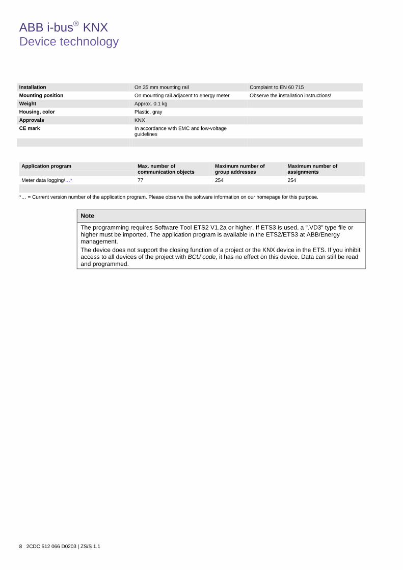
ABB i-bus KNX Device technology
8 2CDC 512 066 D0203 | ZS/S 1.1
Installation On 35 mm mounting rail Complaint to EN 60 715 Mounting position On mounting rail adjacent to energy meter Observe the installation instructions! Weight Approx. 0.1 kg Housing, color Plastic, gray Approvals KNX CE mark In accordance with EMC and low-voltage
guidelines
Application program Max. number of
communication objects Maximum number of group addresses
Maximum number of assignments
Meter data logging/…* 77 254 254
*… = Current version number of the application program. Please observe the software information on our homepage for this purpose.
Note
The programming requires Software Tool ETS2 V1.2a or higher. If ETS3 is used, a ".VD3" type file or higher must be imported. The application program is available in the ETS2/ETS3 at ABB/Energy management. The device does not support the closing function of a project or the KNX device in the ETS. If you inhibit access to all devices of the project with BCU code, it has no effect on this device. Data can still be read and programmed.
ABB i-bus KNX Device technology
ZS/S 1.1 | 2CDC 512 066 D0203 9
2.2 Connection schematic
ZS/S 1.1
1 Label carrier 5 Input telegram LED (yellow) 2 Programming LED 6 Output telegram LED (yellow) 3 Bus connection terminal 7 Error LED (red) 4 Programming key 8 Infrared interface (sidewise)
2CD
C 0
72 0
14 F
0007

ABB i-bus KNX Device technology
10 2CDC 512 066 D0203 | ZS/S 1.1
2.3 Dimensional drawing
ZS/S 1.1
2CD
C 0
72 0
11 F
0007

ABB i-bus KNX Device technology
ZS/S 1.1 | 2CDC 512 066 D0203 11
2.4 Assembly and installation
The Meter Interface Module ZS/S 1.1 is a modular installation device for quick installation in the distribution board on 35 mm mounting rails to EN 60 715.
The connection to the bus is implemented using the supplied bus connection terminal. The device is ready for operation after connection to the bus voltage.
Accessibility to the devices for the purpose of operation, testing, visual inspection, maintenance and repair must be provided compliant to VDE 0100-520.
The device is solely intended for installation in a closed distribution board. This is intended to minimize the occurrence of malfunctions caused by dirt, humidity and external light sources. The communication between the interface and the counters may be subjected to interference with direct incidence of light.
For operation, the Meter Interface Module must be snapped onto the mounting rail arranged flush to the energy meter, to ensure that communication via the infrared interface is assured. No air gap may exist between both devices. An air gap can interfere with the communication and makes the IR interface susceptible to malfunctions. If there is a malfunction of the IR communication, the LED Error will light red when bus voltage is available. In order to avoid the development of an air gap, ensure that the device is not subjected to vibrations after commissioning.
It is important to ensure that the Meter Interface Module and energy meter remain dust-free, dry and clean. In order to guarantee a secure interface function, we recommend checking the devices at regular intervals – taking account of the level of dirt in their environment – and to clean them.
The specifications and notes in the manuals for the corresponding meter must be observed for mounting, installation and commissioning of the DELTAplus, DELTAsingle, ODIN and ODINsingle energy meters.
Energy meter ZS/S
ABB i-bus KNX Device technology
12 2CDC 512 066 D0203 | ZS/S 1.1
Commissioning requirements In order to commission the device, a PC with ETS (from ETS2 V1.2a or higher) as well as an interface to the ABB i-bus®, e.g. via a KNX interface, is required.
The device is ready for operation after connection to the bus voltage. No additional auxiliary voltage is required.
Installation and commissioning may only be carried out by qualified electrical specialists. The appropriate standards, guidelines, regulations and specifications should be observed when planning and setting up electrical installations.
• Protect the device from damp, dirt and damage during transport, storage and operation.
• Only operate the device within the specified technical data limits!
• The device should only be operated in an enclosed housing (distribution board)!
Supplied state The device is supplied with the physical address 15.15.255. The application program is pre-installed. It is therefore only necessary to load group addresses and parameters during commissioning.
However, the complete application program can be reloaded if required. After a change of application program, after an interrupted download or discharge of the device, a longer downtime may result.
Download behavior Depending on the PC that is used, the progress bar for the download may take up to one and a half minutes before it appears due to the complexity of the device.
Assignment of the physical address Assignment and programming of the physical address, group address and parameters are carried out in the ETS.
The device features a programming button for assignment of the physical device address. The red programming LED lights up after the button has been pushed. It switches off as soon as the ETS has assigned the physical address or the programming button is pressed again.
Cleaning If devices become dirty, they can be cleaned using a dry cloth. Should a dry cloth not remove the dirt, the device can be cleaned using a slightly damp cloth and soap solution. Corrosive agents or solutions should never be used.
Maintenance The device is maintenance-free. No repairs should be carried out by unauthorized personnel if damage occurs, e.g. during transport and/or storage. The warranty expires if the device is opened.
ABB i-bus KNX Commissioning
ZS/S 1.1 | 2CDC 512 066 D0203 13
3 Commissioning
3.1 Application program
Programming is carried out with ETS from version ETS2 V1.2a onwards.
The Meter Interface Module ZS/S is delivered with a pre-installed application program. Hence, only group addresses and parameters must be loaded during commissioning. If necessary, the entire user program can be loaded. The device must be discharged beforehand.
Note
After the device is programmed, it may take up to ten seconds before the Meter Interface Module has synchronized with the energy meter. The interface is only ready for operation after this time. Because of the cyclic data exchange between the energy meter and the Meter Interface Module ZS/S 1.1, the average reaction time of the interface is approx. 6 seconds. This means that the requests or changes of meter readings or values are not sent immediately on the bus; they are sent after approx. 6 seconds.
In order to guarantee simple programming, the application program is structured dynamically, i.e. in the basic setting only very few important communication objects and parameters are visible. The full functionality of the application program becomes visible via the activation of the respective parameters.
3.1.1 Conversion
For ABB i-bus® KNX devices, it is possible to adopt the parameter settings and group addresses from earlier versions of the application program as of ETS3.
Furthermore, conversion can be used to transfer the existing parameterization of a device to a different device.
Note
When the term "channels" is used in the ETS, this always means inputs and/or outputs. In order to make the language of the ETS generally valid for as many ABB i-bus® devices as possible, the word "channels" was used here.
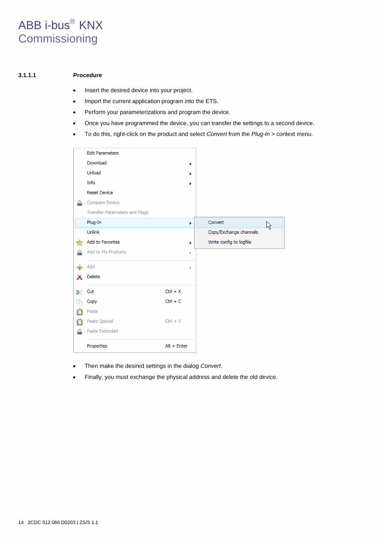
ABB i-bus KNX Commissioning
14 2CDC 512 066 D0203 | ZS/S 1.1
3.1.1.1 Procedure
• Insert the desired device into your project.
• Import the current application program into the ETS.
• Perform your parameterizations and program the device.
• Once you have programmed the device, you can transfer the settings to a second device.
• To do this, right-click on the product and select Convert from the Plug-In > context menu.
• Then make the desired settings in the dialog Convert.
• Finally, you must exchange the physical address and delete the old device.
ABB i-bus KNX Commissioning
ZS/S 1.1 | 2CDC 512 066 D0203 15
3.2 Parameters
The parameterization of the Meter Interface Module is implemented using the Engineering Tool Software ETS from version ETS2 V1.2 or higher. The application program is available in the ETS2/ETS3 at ABB/Energy management.
The following chapter describes the parameters of the ZS/S 1.1 using the parameter windows. The parameter windows feature a dynamic structure so that further parameters may be enabled depending on the parameterization and the function of the outputs.
The default values of the parameters are underlined, e.g.:
Options: yes no

ABB i-bus KNX Commissioning
16 2CDC 512 066 D0203 | ZS/S 1.1
3.2.1 Parameter window General
Higher-level parameter settings for the connected meter can be made in the parameter window General.
Meter type Options: A41, A42, A43, A44 DELTAplus DELTAsingle ODIN ODINsingle
The energy meter connected to the interface is selected using this parameter. Depending on the selected meter type, communication objects, parameters or parameter pages are enabled for the respective meter type.
The following table shows the general parameters (without dependent parameters) and parameter options depending on the selected meter type.
Parameters Parameter options Meter type A-series DELTAplus DELTAsingle ODIN ODINsingle
Configuration Active Energy Meter (direct connected) Active Energy Meter (transformer rated) Combination Meter (direct connected) Combination Meter (transformer rated)
Active Power Meter (direct connected)
Active Power Meter (direct connected) Active Power Meter (transformer rated)
Active Power Meter (direct connected)
Voltage network 4-Wire (L1, L2, L3, N) 3-Wire (L1, L2, L3) 2-Wire (L, N)
2-Wire (L, N) 4-Wire (L1, L2, L3, N) 2-Wire (L, N)
Tariffs no Tariffs 4 Tariffs
no Tariffs 2 Tariffs 4 Tariffs
no Tariffs 2 Tariffs 4 Tariffs
no Tariffs no Tariffs
Register for exported energy
no yes
- - - -
Resettable energy register - - - -
no yes
Sending delay no yes
Send object "In Operation”
no yes

ABB i-bus KNX Commissioning
ZS/S 1.1 | 2CDC 512 066 D0203 17
Configuration Options: Active Energy Meter (direct connected) Active Energy Meter (transformer rated) Combination Meter (direct connected) Combination Meter (transformer rated)
Using this parameter, you can set or display whether the energy meter connected to the interface is an active energy meter or a combination meter. Active power meters only measure the active power or energy. Combination meters also measure the reactive and apparent power or energy.
Note
If a meter of the A4x type with the functionality Platinum is to be read, the option Combination Meter must be selected under the parameter Configuration.
• Active Power Meter/Combination Meter (direct connected): Currents up to 80 A are measured directly
by the meter.
• Active Power Meter/Combination Meter (transformer rated): The communication objects Transformer Ratio Current, Transformer Ratio Voltage and Total Transformer Ratio are enabled.
The following parameters also appear:
Send power and instrument values as Options: secondary values primary values
This parameter is used to set how the power or instrument values are to be sent. This parameter appears only if a transformer rated active energy meter or combination meter of the type A41, A42, A43, A44 and DELTAplus is selected.
• secondary values: The set transformer ratio on the meter is not considered. The sent power values (active, reactive and apparent power) must be multiplied by the transformer ratio (CT x VT) in order to determine the actual value (primary value). The sent currents or voltages must be multiplied by the corresponding current transformer ratio (VT) in order to determine the actual value (primary value).
For more information see: Energy measurement, page 62
• primary values: The set transformer ratio on the meter is considered. The actual or primary values, active, reactive and apparent power, current and voltage are sent.
ABB i-bus KNX Commissioning
18 2CDC 512 066 D0203 | ZS/S 1.1
Send Meter Reading values as Options: secondary values (4 byte object type) primary values (8 byte object type)
This parameter is used to set how the energy values or meter readings are to be sent. This parameter appears only if a transformer rated active energy meter or combination meter of the type A41, A42, A43, A44, DELTAplus or ODIN is selected.
• secondary values: The set transformer ratio on the meter is not considered. The sent energy
values (active or reactive power) must be multiplied by the transformer ratio (CT x VT) in order to determine the actual value (primary value).
For more information see: Energy measurement, page 62
• primary values: The set transformer ratio on the meter is considered. The actual or primary
energy values; Meter Reading, Active Energy; and Meter Reading, Reactive Energy are sent.
Note
Using this option, the energy consumption value is sent via an 8 byte communication object. It is necessary to ensure that the receiving device or software is capable of processing 8 byte values.
Voltage network Options: 4-Wire (L1, L2, L3, N) 3-Wire (L1, L2, L3) 2-Wire (L, N)
Using this parameter, you set the type of voltage network that the energy meter connected to the interface is configured. Depending on the voltage network connected, the communication objects for 2-, 3- or 4-wire networks are displayed.
• 4-Wire (L1, L2, L3, N): 3-phase DELTAplus meters with neutral conductor (3 x 57-288 V or
100-500 V).
• 3-Wire (L1, L2, L3): 3-phase DELTAplus meters without neutral conductor (3 x 100-500 V).
• 2-Wire (L, N): 1-phase DELTAplus meter (1 x 57-288 V) and meters of the A 41 or A42 type.
Note
If a meter of the DELTAsingle or ODINsingle type is selected, the 2-wire voltage network (L, N) is preset and cannot be parameterized.
ABB i-bus KNX Commissioning
ZS/S 1.1 | 2CDC 512 066 D0203 19
Register for exported energy Options: no yes
This parameter is displayed only if a meter of the A4x type is selected, and it enables the objects for the meter readings of the exported active or reactive energy*.
Note
Registers for exported energy are available only for meters of the A4x type with the functionality Bronze, Silver, Gold and Platinum.
• yes: The communication objects for exported active or reactive energy* appear.
Meter Reading, Tot.Act.Energy**
Meter Reading, Active Energy Tariff 1/ 2/ 3/ 4
Meter Reading, Tot.React.Energy**
Meter Reading, Reactive Energy Tariff 1/ 2/ 3/ 4 * The communication objects for the reactive energy exported are displayed only if a combination meter is selected. ** The communication objects Meter Reading, Tot.Act. Energy and Meter Reading, Tot.React.Energy only appear with the
selection of a tariff meter.
Tariffs Options: No Tariffs 2 Tariffs* 4 Tariffs
Using this parameter, you can select if the interface connected to the energy meter features tariff functions.
• 2/4 Tariffs: The communication objects for sending of the tariff meter readings and for
sending/switching the tariffs are displayed. * Available only if a meter of the type DELTAplus or DELTAsingle is selected.
Note
Tariffs are available only for meters of the A4x type with the functionality Silver, Gold and Platinum. Tariff switching via KNX only functions with DELTAplus meters, which have no separate inputs for tariff switching. No tariffs can be parameterized if a meter of the type ODIN or ODINsingle is selected.

ABB i-bus KNX Commissioning
20 2CDC 512 066 D0203 | ZS/S 1.1
Resettable Energy Register Options: no yes
ODINsingle type (OD1365) energy meters feature a resettable energy register similar to a trip meter in a car. The resettable energy register can be used for revenue metering of an accounting period and then can be reset to 0 kWh via KNX. Furthermore, the number of resets is counted and sent.
• yes: The communication objects Meter Reading, Resettable Energy Register, Reset Resettable Energy Register and Send Resets assigned to the resettable energy register are displayed.
Note
The function or the parameter for the resettable energy register is displayed only if a meter of the type ODINsingle is selected.
Sending delay (Device number * Base delay time) Options: no yes
The sending delay is used to minimize the telegram traffic on the bus by ensuring that multiple meters in a KNX system send their readings at different times on the bus.
• no: The telegrams are sent without a delay, i.e. telegrams are sent immediately after a value is requested, e.g. with the communication object Request Meter Reading via the ABB i-bus.
• yes: The parameters Device number and Base delay time for setting the sending delay time are displayed. After every request of a value (meter reading, power value, instrument value), the information is sent via the bus after the set sending delay time has elapsed. The sending delay time is started after every ETS reset, after bus voltage recovery and after tariff switching.
What is the sending delay time? The sending delay time results from the product of the set values:
Sending delay time = device number x base delay time.
In this way, groups of energy meters (up to 255 per group) can be established with the same base delay time. Every one of the up to 255 meters per group is assigned with a number with the parameter Device number. With a simultaneous meter reading request via the communication object Request Meter Reading, the meters of the device series send their readings via the bus.
If the options Sending delay and Send cyclically are activated simultaneously, delayed sending of the telegrams will only occur once directly after an ETS reset, after bus voltage recovery or tariff switching. This means that after each of these events the parameterized sending delay runs before the cyclic sending delay has commenced. With each subsequent send operation, only the cyclic rhythm is observed as the interfaces now send with a time offset.

ABB i-bus KNX Commissioning
ZS/S 1.1 | 2CDC 512 066 D0203 21
Device number [1...255] Options: 1-…255
For assignment of the device number of the energy meter.
Base delay time in s [1…65,535] Options: 1…65,535
For setting the base delay time of the sending delay.
Send object “In Operation” Options: no send value "1" cyclically send value "0" cyclically
The communication object In Operation indicates the correct function of the device on the bus. This cyclic telegram can be monitored by an external device.
Note
After bus voltage recovery, the communication object sends its value after the set sending delay has timed out.
• send value "0/1" cyclically: The communication object In Operation and the parameter Cycle
time in s appear:
Cycle time in s [1…65,535] Options: 1…60…65,535
Here a time interval is set that the communication object In Operation uses to send a telegram cyclically.

ABB i-bus KNX Commissioning
22 2CDC 512 066 D0203 | ZS/S 1.1
3.2.2 Parameter window Meter Reading
In this parameter window, the sending behavior of the meter readings is defined.
The meter readings are always sent as 4 byte values with directly connected meters.
On transformer rated meters, meter readings or energy values can be sent as secondary values (4 byte) or primary values (8 byte).
Depending on the selected meter type and the set parameters, the following communication objects are available for the meter readings:
A-series DELTAplus DELTAsingle ODIN ODINsingle
Active Energy ▪ ▪ ▪ ▪ ▪
Tot.Act.Energy* ▪ ▪ ▪ - -
Active Energy Tariff 1/ 2/ 3/ 4/ ▪ ▪ ▪ - -
Reactive Energy ▪ ▪ - - -
Tot.React.Energy* ▪ ▪ - - -
Reactive Energy Tariff 1/ 2/ 3 /4 ▪ ▪ - - -
Active Energy Exported ▪ - - - -
Total Active Energy Exported* ▪ - - - -
Active Energy Exported Tariff 1/ 2/ 3/ 4
▪ - - - -
Reactive Energy Exported ▪ - - - -
Total Reactive Energy Exported*
▪ - - - -
Reactive Energy Exported Tariff 1/ 2/ 3/ 4
▪ - - - -
Resettable Energy Register - - - - ▪
* The communication objects Total Active Energy (exported) and Total Reactive Energy (exported) are displayed only if a tariff meter is selected.
ABB i-bus KNX Commissioning
ZS/S 1.1 | 2CDC 512 066 D0203 23
Note
Communication objects for the reactive energy meter reading are displayed only if a combination meter is selected in Parameter window General, page 16, parameter Configuration. Communication objects for the meter reading of the (exported) active and reactive energy of tariffs 1-4 only appear when a meter with tariff function is selected (2 or 4 tariffs) in the Parameter window General, page 16, parameter Tariffs. Communication objects for the meter reading of the exported active and reactive energy are displayed only after selection of an active energy meter or combination meter of the type A41, A42, A43, A44 in the Parameter window General, page 16, parameter Register for exported energy.
Reading of the momentary meter readings can be implemented via reading of the communication object values via Value_Read, e.g. with the assistance of the Engineering Tool Software ETS. The option of cyclically sending the meter readings or sending on request continues to apply. The meter readings are sent via a 4 byte communication object with a resolution of 1 Wh/varh. Thus meter readings up to a max. of 2,147,483,647 Wh/varh (2.147 GWh/Gvarh) can be sent. If values received from the connected meter are greater than the max. value, the max. value of 2,147,483,647 Wh/varh is always sent.
Send meter reading cyclically Options: no yes
The meter readings are sent cyclically via the bus with this setting.
• yes: The parameter Cycle time in s is displayed. Using this parameter, the send interval at which the meter reading/the meter readings is/are to be sent is set. Multiple meters that send with the same cycle time can send at staggered times using the sending delay time (if it is parameterized) in order to avoid possible communication problems. Cyclical sending is interrupted as soon as communication to the energy meters cannot be established. The meter readings of the active and reactive energy are sent (only when a combination meter is selected). Only the tariff that is currently active and the sum of the tariffs are sent with tariff meters.
ABB i-bus KNX Commissioning
24 2CDC 512 066 D0203 | ZS/S 1.1
Cycle time in s [1…172,800] Options: 1…900...172,800
The parameter is displayed if the option Send cyclically has been selected. Here the time is set for cyclically sending the meter readings.
Note
If Sending delay and Send cyclically are activated simultaneously, timed offsetting of the meter reading telegrams will only occur once directly after an ETS reset, after bus voltage recovery or tariff switching, i.e. after each of these events the meter waits for the parameterized sending delay time before beginning with the cyclic sending process. With each subsequent send operation only the cyclic rhythm is observed as the meters now send with a time offset.
Send meter reading on request Options: no yes
With this setting, the meter readings are sent on request via a separate communication object.
• yes: The communication object Request Meter Reading is displayed. This communication object enables active reading of the momentary meter readings. After receiving a meter reading request telegram with the value 1, the meter reading is sent after a sending delay (if parameterized) via the bus.
The sending delay time prevents simultaneous sending of telegrams, if multiple meters react to the same meter reading request telegram.
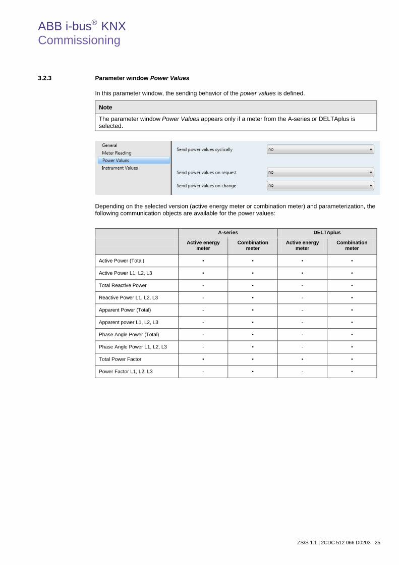
ABB i-bus KNX Commissioning
ZS/S 1.1 | 2CDC 512 066 D0203 25
3.2.3 Parameter window Power Values
In this parameter window, the sending behavior of the power values is defined.
Note
The parameter window Power Values appears only if a meter from the A-series or DELTAplus is selected.
Depending on the selected version (active energy meter or combination meter) and parameterization, the following communication objects are available for the power values:
A-series DELTAplus
Active energy meter
Combination meter
Active energy meter
Combination meter
Active Power (Total) ▪ ▪ ▪ ▪
Active Power L1, L2, L3 ▪ ▪ ▪ ▪
Total Reactive Power - ▪ - ▪
Reactive Power L1, L2, L3 - ▪ - ▪
Apparent Power (Total) - ▪ - ▪
Apparent power L1, L2, L3 - ▪ - ▪
Phase Angle Power (Total) - ▪ - ▪
Phase Angle Power L1, L2, L3 - ▪ - ▪
Total Power Factor ▪ ▪ ▪ ▪
Power Factor L1, L2, L3 - ▪ - ▪

ABB i-bus KNX Commissioning
26 2CDC 512 066 D0203 | ZS/S 1.1
Note
The parameters or communication objects for reactive and apparent power as well as phase angle are only displayed if, in the Parameter window General, page 16, a combination meter (direct connected or transformer rated) has been selected under parameter Configuration. If an energy meter is parameterized for 3- or 4-wire voltage networks, the following communication objects are displayed: Total Active Power Active Power L1, L2, L3 Total Reactive and Apparent Power * Reactive and Apparent Power L1, L2, L3* Total Phase Angle Power* Phase Angle Current L1, L2, L3* Total Power Factor Power Factor L1, L2, L3 * These communication objects are only displayed with the selection of the combination meter in the Parameter window
General, page 16, parameter Configuration.
Reading of the actual power values can be implemented via reading of the communication object values via Value_Read, e.g. with the assistance of the Engineering Tool Software ETS. The option of Send power values cyclically; Send power values on request or Send power values on change continues to apply.

ABB i-bus KNX Commissioning
ZS/S 1.1 | 2CDC 512 066 D0203 27
Send power values cyclically Options: no yes
• yes: The parameter Cycle time in s is displayed.
Cycle time in s [1…172,800] Options: 1…900...172,800
Here the time is set for cyclically sending all power values via the bus. The send interval is defined with the parameter Cycle time in s. Multiple meters that send with the same cycle time can send at staggered times using the sending delay time (if it is parameterized) in order to avoid possible communication problems.
Note
If the sending delay and cyclic sending of the power values are activated, the sending delay time only runs once directly after an ETS reset, after bus voltage recovery or tariff switching. After the sending delay time has timed out, the cyclic send process commences. With each additional send operation, only the cycle time is observed as the interface now sends with a time offset. Cyclical sending is interrupted as soon as communication to the energy meters cannot be established.
Conversion of the cycle time in seconds
900 s = 15 minutes 3,600 s = 1 hour
86,400 s = 1 day 172,800 s = 2 days
Send power values on request Options: no yes
• yes: The communication object Request Power Values is displayed. This communication object
enables active reading of the momentary power values. After receiving a telegram with a request with the value 1, all the momentary values (active power, reactive power*, apparent power*, phase angle* and power factor) are sent after a sending delay time (if parameterized) via the bus. The sending delay time prevents simultaneous sending of telegrams, if several meters respond to the same request for power values.
* Only with the selection of the combination meter in the Parameter window General, page 16, parameter Configuration.

ABB i-bus KNX Commissioning
28 2CDC 512 066 D0203 | ZS/S 1.1
Send power values on change Options: no yes
• yes: The parameter values for entering the change values are displayed. If no change of the value
occurs, the momentary power values are sent after the set cycle time (if parameterized) has timed out. After bus voltage recovery, programming and ETS reset, the power values whose change value is greater than or equal to ± 1 (0 = do not send) are sent after the sending delay time (if parameterized) has elapsed.
Send Active Power in W at +/- [0…65,535] Options: 0…65,535 (0 = do not send)
The change value to be entered here applies for the communication objects Active Power (Total; Active Power L1, L2, L3)*. If the preset change value is exceeded or undershot, the corresponding momentary active power value is sent on the bus.
The change value in meters with a transformer ratio always relates to the set parameter option (send as primary values or as secondary values) of the parameter Send power and instrument values in the Parameter window General, page 16. * These objects are only displayed with the selection of a 3-wire network or 4-wire network in the Parameter window
General, page 16, parameter Voltage network.
Send Reactive Power in var at +/- [0…65,535] Options: 0…65,535 (0 = do not send)
This parameter is only displayed as soon as a combination meter has been selected in the Parameter window General, page 16, parameter Configuration.
The change value to be entered here applies for the communication objects Reactive Power (Total; Reactive Power L1, L2, L3)*. If the preset change value is exceeded or undershot, the corresponding momentary reactive power value is sent on the bus.
The change value in meters with a transformer ratio always relates to the set parameter option (send as primary values or as secondary values) of the parameter Send power and instrument values in the Parameter window General, page 16. * These objects are only displayed with the selection of a 3-wire network or 4-wire network in the Parameter window
General, page 16, parameter Voltage Network.

ABB i-bus KNX Commissioning
ZS/S 1.1 | 2CDC 512 066 D0203 29
Send Apparent Power in VA at +/- [0…65,535] Options: 0…65,535 (0 = do not send)
This parameter is only displayed as soon as a combination meter has been selected in the Parameter window General, page 16, parameter Configuration.
The change value to be entered here applies for the communication objects Apparent Power (Total; Apparent Power L1, L2, L3)*. If the preset change value is exceeded or undershot, the corresponding momentary apparent power value is sent on the bus.
The change value in meters with a transformer ratio always relates to the set parameter option (send as primary values or as secondary values) of the parameter Send power and instrument values in the Parameter window General, page 16. * These objects are only displayed with the selection of a 3-wire network or 4-wire network in the Parameter window
General, page 16, parameter Voltage Network.
Send Phase Angle Power in degrees at +/- [0…90] Options: 0…65,535 (0 = do not send)
This parameter is only displayed as soon as a combination meter has been selected in the Parameter window General, page 16, parameter Configuration.
The change value to be entered here applies for the communication objects Phase Angle Power (Total; Phase Angle Power L1, L2, L3)*.
If the preset change value is exceeded or undershot, the corresponding momentary phase angle power value is sent on the bus. * These objects are only displayed with the selection of a 3-wire network or 4-wire network in the Parameter window
General, page 16, parameter Voltage network.
Send Power Factor at +/- 0.01 * Value [0…100] Options: 0 …100
The change value to be entered here applies for the communication objects Power Factor (Total; Power Factor L1, L2, L3)*. If the preset change value is exceeded or undershot, the corresponding momentary power factor value is sent on the bus. * These objects are only displayed with the selection of a 3-wire network or 4-wire network in the Parameter window
General, page 16, parameter Voltage network.

ABB i-bus KNX Commissioning
30 2CDC 512 066 D0203 | ZS/S 1.1
3.2.4 Parameter window Instrument Values
In this parameter window, the sending behavior of the instrument values is defined.
Note
The parameter window Instrument Values appears only if a meter from the A-series or DELTAplus is selected.
Depending on the selected configuration (active energy meter or combination meter) and parameterized voltage network, the following communication objects are available for the instrument values:
A-series DELTAplus
Active power meter Combination meter Active power meter Combination meter
Current (L1, L2, L3) ▪ ▪ ▪ ▪
Current N* - ▪ - -
Voltage (L1-N, L2-N, L3-N)
▪ ▪ ▪ ▪
Voltage L1-L2, L2-L3, L1-L3**
▪ ▪ ▪ ▪
Frequency*** ▪ ▪ ▪ ▪
Phase Angle Current (L1, L2, L3)****
- ▪ - ▪
Phase Angle Voltage (L1, L2, L3)****
- ▪ - ▪
Total Quadrant**** - ▪ - ▪
Quadrant L1, L2, L3**** - ▪ - ▪
* The communication object Current N is displayed only if a combination meter of the A4x type is selected. ** The communication objects Voltage L1-L3 are displayed only if a meter of the A4x type for 3-wire or 4-wire networks is
selected. *** The communication object Frequency is inactive and does not send any values if a meter from the A-series with the
functionality Steel is selected. **** These communication objects are displayed only if a combination meter is selected.
Reading of the actual instrument values can be implemented via reading of the communication object values via Value_Read, e.g. with the assistance of the Engineering Tool Software ETS. The option of cyclically sending the instrument values, sending the instrument values on request or when a change occurs continues to apply.

ABB i-bus KNX Commissioning
ZS/S 1.1 | 2CDC 512 066 D0203 31
Send instrument values cyclically Options: no yes
• yes: The parameter Cycle time in s is displayed.
Cycle time in s [1…172,800] Options: 1...900...172,800
Here the time is set for cyclically sending all instrument values via the bus. The send interval is defined with the parameter Cycle time in s. Multiple meters that send with the same cycle time can send at staggered times using the sending delay time (if it is parameterized) in order to avoid possible communication problems.
Note
If the sending delay and cyclic sending of the instrument values are activated, the sending delay time only runs once directly after an ETS reset, after bus voltage recovery or tariff switching. After the sending delay time has timed out, the cyclic send process commences. With each additional send operation, only the cycle time is observed as the interface now sends with a time offset. Cyclical sending is interrupted as soon as communication to the energy meters cannot be established.
Conversion of the cycle time in seconds
900 s = 15 minutes 3,600 s = 1 hour
86,400 s = 1 day 172,800 s = 2 days
Send instrument values on request Options: no yes
• yes: The communication object Request Instrument Values is displayed. This communication object
enables active reading of the momentary instrument values. After receiving a telegram with a request with the value 1, all the momentary values (current, voltage, frequency, phase angle current/voltage, quadrant) are sent after a sending delay time (if parameterized) via the bus. The sending delay time prevents simultaneous sending of telegrams, if several meters respond to the same request for instrument values.

ABB i-bus KNX Commissioning
32 2CDC 512 066 D0203 | ZS/S 1.1
Send instrument values on change Options: no yes
• yes: The parameter values for entering the change values are displayed. If no change of the value
occurs, the momentary instrument values are sent after the set cycle time (if parameterized) has timed out. After bus voltage recovery, programming and ETS reset, the instrument values whose change value is greater than or equal to ± 1 (0 = do not send) are sent after the sending delay time (if parameterized) has elapsed.
Send Current in mA at +/- 100 mA Value [0…65,535] Options: 0…65,535 (0 = do not send)
The change value to be entered here relates to the communication objects Current (Current L1, L2, L3, N). If the preset change value is exceeded or undershot with one of these communication objects, the momentary current value is sent. If the value 0 is entered, the current value is not sent.
The change value is calculated on the basis of 100 mA and the value or factor to be entered, e.g.:
Change value = Basis x factor = 100 mA x 10 = 1,000 mA = 1 A
The change value in meters with a transformer ratio always relates to the set parameter option (send as primary values or as secondary values) of the parameter Send power and instrument values in the Parameter window General, page 16.

ABB i-bus KNX Commissioning
ZS/S 1.1 | 2CDC 512 066 D0203 33
Send Voltage in mV at +/- 10 mV Value [0…65,535] Options: 0…65,535 (0 = do not send)
The change value to be entered here relates to the communication objects Voltage (Voltage L1-N, L2-N, L3-N, L1-L2, L2-L3, L1-L3). If the preset change value is exceeded or undershot with one of these communication objects, the momentary voltage values are sent on the bus. If the value 0 is entered, the voltage value is not sent.
The change value is calculated on the basis of 10 mV and the value or factor to be entered, e.g.:
Change value = Basis x factor = 10 mV x 1,000 = 10,000 mV = 10 V
The change value in meters with a transformer ratio always relates to the set parameter option (send as primary values or as secondary values) of the parameter Send power and instrument values in the Parameter window General, page 16.
Note
When using transformers it is important to observe that practical values which are dependent on the transformer are used.
Send Frequency in Hz at +/- 0.1 Hz * Value [0…100] Options: 0…100 (0 = do not send)
If the preset change value is exceeded or undershot, the corresponding actual frequency is sent on the bus. If the value 0 is entered, the voltage value is not sent, e.g.
Change value = Basis x factor = 0.1 Hz x 10 = 1 Hz
ABB i-bus KNX Commissioning
34 2CDC 512 066 D0203 | ZS/S 1.1
Send Phase Angle Voltage in degrees at +/- [0...90] Options: 0…90 (0 = do not send)
These parameters are only displayed with the selection of the combination meter in the Parameter window General, page 16, parameter Configuration.
The change value to be entered here relates to the communication objects Phase Angle Current (Phase Angle Current L1, L2, L3) or Phase Angle Voltage (Phase Angle Voltage L1, L2, L3). If the preset change value is exceeded or undershot with one of these communication objects, the momentary phase angle current or voltage values are sent on the bus.
Send Quadrant on change Options: no yes
This parameter is only displayed with the selection of the combination meter in the Parameter window General, page 16, parameter Configuration.
• yes: The communication objects Quadrant (Total Quadrant; Quadrant L1, L2, L3) are displayed. If the communication object value changes with the communication object Quadrant (Total and/or Quadrant L1, L2, L3), the momentary quadrant is sent on the bus.
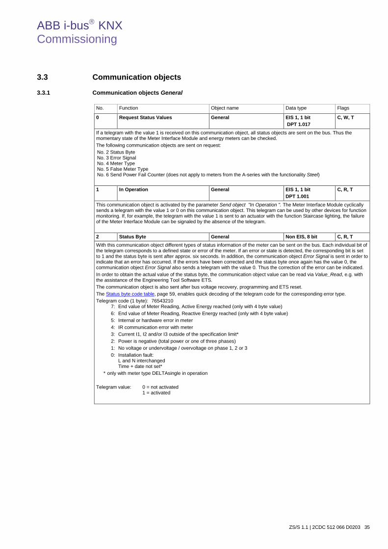
ABB i-bus KNX Commissioning
ZS/S 1.1 | 2CDC 512 066 D0203 35
3.3 Communication objects
3.3.1 Communication objects General
No. Function Object name Data type Flags
0 Request Status Values General EIS 1, 1 bit DPT 1.017
C, W, T
If a telegram with the value 1 is received on this communication object, all status objects are sent on the bus. Thus the momentary state of the Meter Interface Module and energy meters can be checked. The following communication objects are sent on request: No. 2 Status Byte No. 3 Error Signal No. 4 Meter Type No. 5 False Meter Type No. 6 Send Power Fail Counter (does not apply to meters from the A-series with the functionality Steel) 1 In Operation General EIS 1, 1 bit
DPT 1.001 C, R, T
This communication object is activated by the parameter Send object "In Operation ". The Meter Interface Module cyclically sends a telegram with the value 1 or 0 on this communication object. This telegram can be used by other devices for function monitoring. If, for example, the telegram with the value 1 is sent to an actuator with the function Staircase lighting, the failure of the Meter Interface Module can be signaled by the absence of the telegram.
2 Status Byte General Non EIS, 8 bit C, R, T With this communication object different types of status information of the meter can be sent on the bus. Each individual bit of the telegram corresponds to a defined state or error of the meter. If an error or state is detected, the corresponding bit is set to 1 and the status byte is sent after approx. six seconds. In addition, the communication object Error Signal is sent in order to indicate that an error has occurred. If the errors have been corrected and the status byte once again has the value 0, the communication object Error Signal also sends a telegram with the value 0. Thus the correction of the error can be indicated. In order to obtain the actual value of the status byte, the communication object value can be read via Value_Read, e.g. with the assistance of the Engineering Tool Software ETS. The communication object is also sent after bus voltage recovery, programming and ETS reset. The Status byte code table, page 59, enables quick decoding of the telegram code for the corresponding error type. Telegram code (1 byte): 76543210
7: End value of Meter Reading, Active Energy reached (only with 4 byte value) 6: End value of Meter Reading, Reactive Energy reached (only with 4 byte value) 5: Internal or hardware error in meter 4: IR communication error with meter 3: Current I1, I2 and/or I3 outside of the specification limit* 2: Power is negative (total power or one of three phases) 1: No voltage or undervoltage / overvoltage on phase 1, 2 or 3 0: Installation fault: L and N interchanged Time + date not set*
* only with meter type DELTAsingle in operation Telegram value: 0 = not activated
1 = activated
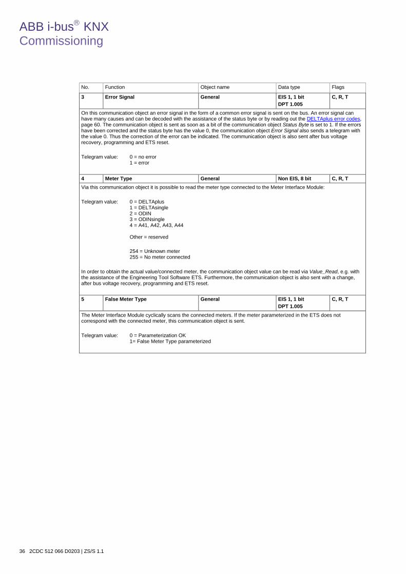
ABB i-bus KNX Commissioning
36 2CDC 512 066 D0203 | ZS/S 1.1
No. Function Object name Data type Flags
3 Error Signal General EIS 1, 1 bit DPT 1.005
C, R, T
On this communication object an error signal in the form of a common error signal is sent on the bus. An error signal can have many causes and can be decoded with the assistance of the status byte or by reading out the DELTAplus error codes, page 60. The communication object is sent as soon as a bit of the communication object Status Byte is set to 1. If the errors have been corrected and the status byte has the value 0, the communication object Error Signal also sends a telegram with the value 0. Thus the correction of the error can be indicated. The communication object is also sent after bus voltage recovery, programming and ETS reset. Telegram value: 0 = no error
1 = error
4 Meter Type General Non EIS, 8 bit C, R, T Via this communication object it is possible to read the meter type connected to the Meter Interface Module: Telegram value: 0 = DELTAplus
1 = DELTAsingle 2 = ODIN 3 = ODINsingle 4 = A41, A42, A43, A44 Other = reserved
254 = Unknown meter 255 = No meter connected
In order to obtain the actual value/connected meter, the communication object value can be read via Value_Read, e.g. with the assistance of the Engineering Tool Software ETS. Furthermore, the communication object is also sent with a change, after bus voltage recovery, programming and ETS reset.
5 False Meter Type General EIS 1, 1 bit DPT 1.005
C, R, T
The Meter Interface Module cyclically scans the connected meters. If the meter parameterized in the ETS does not correspond with the connected meter, this communication object is sent. Telegram value: 0 = Parameterization OK
1= False Meter Type parameterized
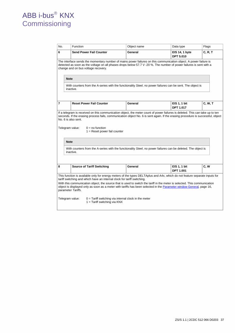
ABB i-bus KNX Commissioning
ZS/S 1.1 | 2CDC 512 066 D0203 37
No. Function Object name Data type Flags
6 Send Power Fail Counter General EIS 14, 1 byte DPT 5.010
C, R, T
The interface sends the momentary number of mains power failures on this communication object. A power failure is detected as soon as the voltage on all phases drops below 57.7 V -20 %. The number of power failures is sent with a change and on bus voltage recovery.
Note
With counters from the A-series with the functionality Steel, no power failures can be sent. The object is inactive.
7 Reset Power Fail Counter General EIS 1, 1 bit
DPT 1.017 C, W, T
If a telegram is received on this communication object, the meter count of power failures is deleted. This can take up to ten seconds. If the erasing process fails, communication object No. 6 is sent again. If the erasing procedure is successful, object No. 6 is also sent. Telegram value: 0 = no function
1 = Reset power fail counter
Note
With counters from the A-series with the functionality Steel, no power failures can be deleted. The object is inactive.
8 Source of Tariff Switching General EIS 1, 1 bit DPT 1.001
C, W
This function is available only for energy meters of the types DELTAplus and A4x, which do not feature separate inputs for tariff switching and which have an internal clock for tariff switching. With this communication object, the source that is used to switch the tariff in the meter is selected. This communication object is displayed only as soon as a meter with tariffs has been selected in the Parameter window General, page 16, parameter Tariffs. Telegram value: 0 = Tariff switching via internal clock in the meter
1 = Tariff switching via KNX

ABB i-bus KNX Commissioning
38 2CDC 512 066 D0203 | ZS/S 1.1
3.3.2 Communication objects Meter Reading
No. Function Object name Data type Flags
10 Request Meter Reading Meter reading EIS 1, 1 bit DPT 1.017
C, W, T
The momentary meter readings are requested via the telegram with the value 1 on this communication object. The request applies for the communication objects No. 11-30. The momentary meter readings – depending on the meters used – are sent on the bus after the sending delay time (if parameterized).
Telegram value: 0 = no function
1 = Request Meter Reading
11 12 13 14 15
Tot.Act.Energy* Active Energy, Tariff 1 Active Energy, Tariff 2 Active Energy, Tariff 3 Active Energy, Tariff 4
Meter reading Meter reading Meter reading Meter reading Meter reading
EIS 11, 4 byte DPT 13.010 or Non EIS, 8 byte DPT 29.010
C, R, T
On these communication objects the momentary meter readings for active energy are sent. If a meter with 2** or 4 tariffs is selected in the Parameter window General, page 16, communication objects No. 11-13 or 11-15 are displayed. If a tariff meter has been parameterized, communication object No. 11 sends the meter reading of the sum of all tariffs of the consumed active energy, whereas communication objects No. 12-15 send the consumed active energy of the respective tariffs. Only the tariff that is currently active and the sum of the tariffs are sent. The communication object is also sent after bus voltage recovery, programming and ETS reset. With the 4 byte communication object, meter readings up to a max. of 2,147,483,647 Wh (2.147 GWh) and a resolution of 1 Wh can be sent. If values received from the connected meter are greater than the max. value, the end value of 2,147,483,647 Wh and the status bit No. 7 (end value of Meter Reading, Active Energy reached) are always sent. If a transformer rated meter is used, the energy consumption values of the active energy are sent as the primary values. For this purpose an 8 byte communication object is displayed. It is necessary to ensure that the receiving device or software is capable of processing 8 byte values. * The communication object Tot.Act.Energy is only displayed if a tariff meter has been selected and indicates the sum of the
meter readings of tariff 1 + 2 or tariff 1 + 2 + 3 + 4. ** 2 tariffs available only for meters of the configuration DELTAplus.
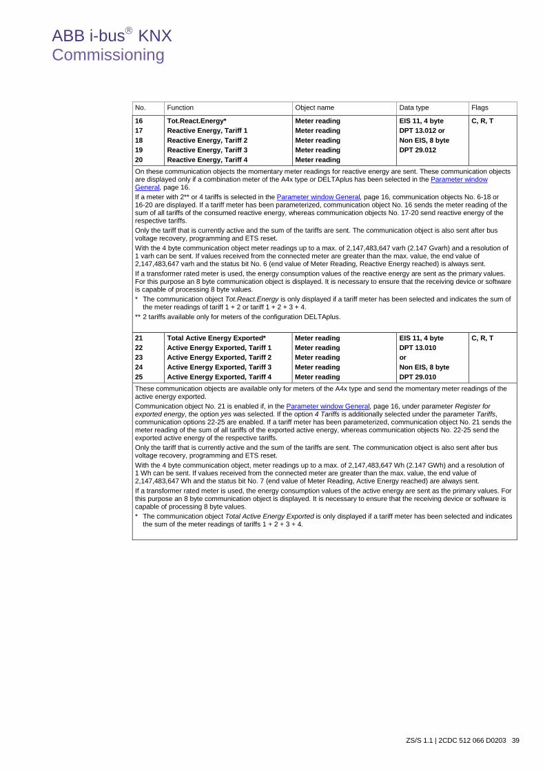
ABB i-bus KNX Commissioning
ZS/S 1.1 | 2CDC 512 066 D0203 39
No. Function Object name Data type Flags
16 17 18 19 20
Tot.React.Energy* Reactive Energy, Tariff 1 Reactive Energy, Tariff 2 Reactive Energy, Tariff 3 Reactive Energy, Tariff 4
Meter reading Meter reading Meter reading Meter reading Meter reading
EIS 11, 4 byte DPT 13.012 or Non EIS, 8 byte DPT 29.012
C, R, T
On these communication objects the momentary meter readings for reactive energy are sent. These communication objects are displayed only if a combination meter of the A4x type or DELTAplus has been selected in the Parameter window General, page 16. If a meter with 2** or 4 tariffs is selected in the Parameter window General, page 16, communication objects No. 6-18 or 16-20 are displayed. If a tariff meter has been parameterized, communication object No. 16 sends the meter reading of the sum of all tariffs of the consumed reactive energy, whereas communication objects No. 17-20 send reactive energy of the respective tariffs. Only the tariff that is currently active and the sum of the tariffs are sent. The communication object is also sent after bus voltage recovery, programming and ETS reset. With the 4 byte communication object meter readings up to a max. of 2,147,483,647 varh (2.147 Gvarh) and a resolution of 1 varh can be sent. If values received from the connected meter are greater than the max. value, the end value of 2,147,483,647 varh and the status bit No. 6 (end value of Meter Reading, Reactive Energy reached) is always sent. If a transformer rated meter is used, the energy consumption values of the reactive energy are sent as the primary values. For this purpose an 8 byte communication object is displayed. It is necessary to ensure that the receiving device or software is capable of processing 8 byte values. * The communication object Tot.React.Energy is only displayed if a tariff meter has been selected and indicates the sum of
the meter readings of tariff 1 + 2 or tariff 1 + 2 + 3 + 4. ** 2 tariffs available only for meters of the configuration DELTAplus.
21 22 23 24 25
Total Active Energy Exported* Active Energy Exported, Tariff 1 Active Energy Exported, Tariff 2 Active Energy Exported, Tariff 3 Active Energy Exported, Tariff 4
Meter reading Meter reading Meter reading Meter reading Meter reading
EIS 11, 4 byte DPT 13.010 or Non EIS, 8 byte DPT 29.010
C, R, T
These communication objects are available only for meters of the A4x type and send the momentary meter readings of the active energy exported. Communication object No. 21 is enabled if, in the Parameter window General, page 16, under parameter Register for exported energy, the option yes was selected. If the option 4 Tariffs is additionally selected under the parameter Tariffs, communication options 22-25 are enabled. If a tariff meter has been parameterized, communication object No. 21 sends the meter reading of the sum of all tariffs of the exported active energy, whereas communication objects No. 22-25 send the exported active energy of the respective tariffs. Only the tariff that is currently active and the sum of the tariffs are sent. The communication object is also sent after bus voltage recovery, programming and ETS reset. With the 4 byte communication object, meter readings up to a max. of 2,147,483,647 Wh (2.147 GWh) and a resolution of 1 Wh can be sent. If values received from the connected meter are greater than the max. value, the end value of 2,147,483,647 Wh and the status bit No. 7 (end value of Meter Reading, Active Energy reached) are always sent. If a transformer rated meter is used, the energy consumption values of the active energy are sent as the primary values. For this purpose an 8 byte communication object is displayed. It is necessary to ensure that the receiving device or software is capable of processing 8 byte values. * The communication object Total Active Energy Exported is only displayed if a tariff meter has been selected and indicates
the sum of the meter readings of tariffs 1 + 2 + 3 + 4.
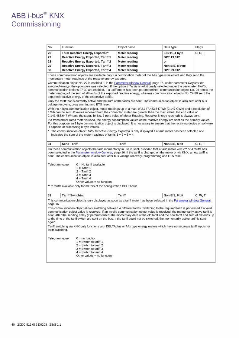
ABB i-bus KNX Commissioning
40 2CDC 512 066 D0203 | ZS/S 1.1
No. Function Object name Data type Flags
26 27 28 29 30
Total Reactive Energy Exported* Reactive Energy Exported, Tariff 1 Reactive Energy Exported, Tariff 2 Reactive Energy Exported, Tariff 3 Reactive Energy Exported, Tariff 4
Meter reading Meter reading Meter reading Meter reading Meter reading
EIS 11, 4 byte DPT 13.012 or Non EIS, 8 byte DPT 29.012
C, R, T
These communication objects are available only if a combination meter of the A4x type is selected, and they send the momentary meter readings of the reactive energy exported. Communication object No. 27 is enabled if, in the Parameter window General, page 16, under parameter Register for exported energy, the option yes was selected. If the option 4 Tariffs is additionally selected under the parameter Tariffs, communication options 27-30 are enabled. If a tariff meter has been parameterized, communication object No. 26 sends the meter reading of the sum of all tariffs of the exported reactive energy, whereas communication objects No. 27-30 send the exported reactive energy of the respective tariffs. Only the tariff that is currently active and the sum of the tariffs are sent. The communication object is also sent after bus voltage recovery, programming and ETS reset. With the 4 byte communication object, meter readings up to a max. of 2,147,483,647 Wh (2.147 GWh) and a resolution of 1 Wh can be sent. If values received from the connected meter are greater than the max. value, the end value of 2,147,483,647 Wh and the status bit No. 7 (end value of Meter Reading, Reactive Energy reached) is always sent. If a transformer rated meter is used, the energy consumption values of the reactive energy are sent as the primary values. For this purpose an 8 byte communication object is displayed. It is necessary to ensure that the receiving device or software is capable of processing 8 byte values. * The communication object Total Reactive Energy Exported is only displayed if a tariff meter has been selected and
indicates the sum of the meter readings of tariffs 1 + 2 + 3 + 4. 31 Send Tariff Tariff Non EIS, 8 bit C, R, T On these communication objects the tariff momentarily in use is sent, provided that a tariff meter with 2** or 4 tariffs has been selected in the Parameter window General, page 16. If the tariff is changed on the meter or via KNX, a new tariff is sent. The communication object is also sent after bus voltage recovery, programming and ETS reset. Telegram value: 0 = No tariff available
1 = Tariff 1 2 = Tariff 2 3 = Tariff 3 4 = Tariff 4 Other values = no function
** 2 tariffs available only for meters of the configuration DELTAplus.
32 Tariff Switching Tariff Non EIS, 8 bit C, W, T This communication object is only displayed as soon as a tariff meter has been selected in the Parameter window General, page 16. This communication object allows switching between 4 different tariffs. Switching to the required tariff is performed if a valid communication object value is received. If an invalid communication object value is received, the momentarily active tariff is sent. After the sending delay (if parameterized) the momentary data of the old tariff and the new tariff and sum of all tariffs up to the time of the tariff switch are sent on the bus. If the tariff could not be switched, the momentarily active tariff is sent again. Tariff switching via KNX only functions with DELTAplus or A4x type energy meters which have no separate tariff inputs for tariff switching. Telegram value: 0 = no function
1 = Switch to tariff 1 2 = Switch to tariff 2 3 = Switch to tariff 3 4 = Switch to tariff 4 Other values = no function
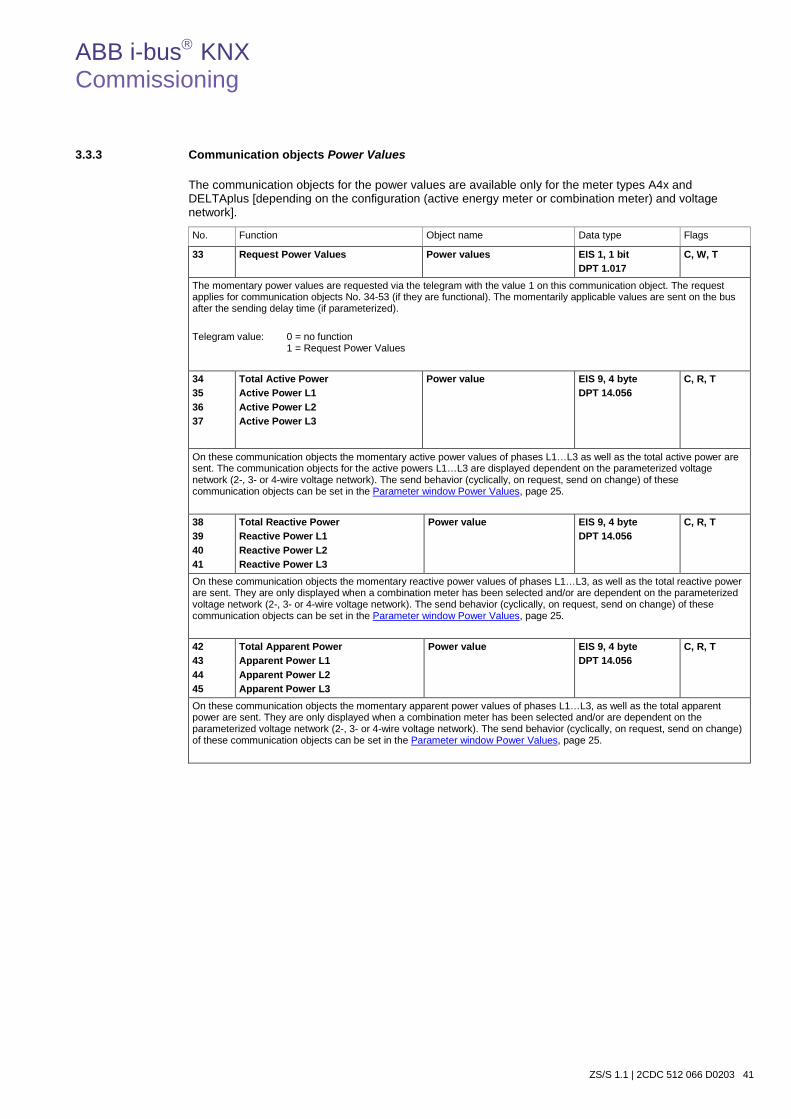
ABB i-bus KNX Commissioning
ZS/S 1.1 | 2CDC 512 066 D0203 41
3.3.3 Communication objects Power Values
The communication objects for the power values are available only for the meter types A4x and DELTAplus [depending on the configuration (active energy meter or combination meter) and voltage network].
No. Function Object name Data type Flags
33 Request Power Values Power values EIS 1, 1 bit DPT 1.017
C, W, T
The momentary power values are requested via the telegram with the value 1 on this communication object. The request applies for communication objects No. 34-53 (if they are functional). The momentarily applicable values are sent on the bus after the sending delay time (if parameterized). Telegram value: 0 = no function
1 = Request Power Values
34 35 36 37
Total Active Power Active Power L1 Active Power L2 Active Power L3
Power value
EIS 9, 4 byte DPT 14.056
C, R, T
On these communication objects the momentary active power values of phases L1…L3 as well as the total active power are sent. The communication objects for the active powers L1…L3 are displayed dependent on the parameterized voltage network (2-, 3- or 4-wire voltage network). The send behavior (cyclically, on request, send on change) of these communication objects can be set in the Parameter window Power Values, page 25.
38 39 40 41
Total Reactive Power Reactive Power L1 Reactive Power L2 Reactive Power L3
Power value EIS 9, 4 byte DPT 14.056
C, R, T
On these communication objects the momentary reactive power values of phases L1…L3, as well as the total reactive power are sent. They are only displayed when a combination meter has been selected and/or are dependent on the parameterized voltage network (2-, 3- or 4-wire voltage network). The send behavior (cyclically, on request, send on change) of these communication objects can be set in the Parameter window Power Values, page 25.
42 43 44 45
Total Apparent Power Apparent Power L1 Apparent Power L2 Apparent Power L3
Power value EIS 9, 4 byte DPT 14.056
C, R, T
On these communication objects the momentary apparent power values of phases L1…L3, as well as the total apparent power are sent. They are only displayed when a combination meter has been selected and/or are dependent on the parameterized voltage network (2-, 3- or 4-wire voltage network). The send behavior (cyclically, on request, send on change) of these communication objects can be set in the Parameter window Power Values, page 25.
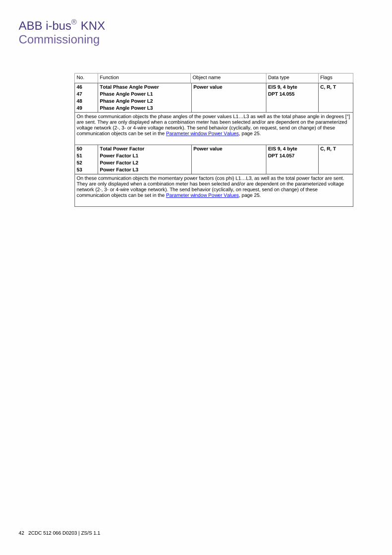
ABB i-bus KNX Commissioning
42 2CDC 512 066 D0203 | ZS/S 1.1
No. Function Object name Data type Flags
46 47 48 49
Total Phase Angle Power Phase Angle Power L1 Phase Angle Power L2 Phase Angle Power L3
Power value EIS 9, 4 byte DPT 14.055
C, R, T
On these communication objects the phase angles of the power values L1…L3 as well as the total phase angle in degrees [°] are sent. They are only displayed when a combination meter has been selected and/or are dependent on the parameterized voltage network (2-, 3- or 4-wire voltage network). The send behavior (cyclically, on request, send on change) of these communication objects can be set in the Parameter window Power Values, page 25. 50 51 52 53
Total Power Factor Power Factor L1 Power Factor L2 Power Factor L3
Power value EIS 9, 4 byte DPT 14.057
C, R, T
On these communication objects the momentary power factors (cos phi) L1…L3, as well as the total power factor are sent. They are only displayed when a combination meter has been selected and/or are dependent on the parameterized voltage network (2-, 3- or 4-wire voltage network). The send behavior (cyclically, on request, send on change) of these communication objects can be set in the Parameter window Power Values, page 25.
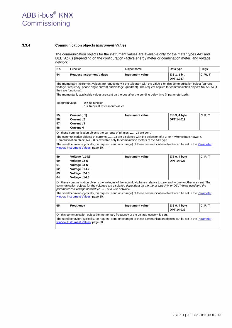
ABB i-bus KNX Commissioning
ZS/S 1.1 | 2CDC 512 066 D0203 43
3.3.4 Communication objects Instrument Values
The communication objects for the instrument values are available only for the meter types A4x and DELTAplus [depending on the configuration (active energy meter or combination meter) and voltage network].
No. Function Object name Data type Flags
54 Request Instrument Values Instrument value EIS 1, 1 bit DPT 1.017
C, W, T
The momentary instrument values are requested via the telegram with the value 1 on this communication object (current, voltage, frequency, phase angle current and voltage, quadrant). The request applies for communication objects No. 55-74 (if they are functional). The momentarily applicable values are sent on the bus after the sending delay time (if parameterized). Telegram value: 0 = no function
1 = Request Instrument Values
55 56 57 58
Current (L1) Current L2 Current L3 Current N
Instrument value EIS 9, 4 byte DPT 14.019
C, R, T
On these communication objects the currents of phases L1…L3 are sent. The communication objects of currents L1…L3 are displayed with the selection of a 3- or 4-wire voltage network. Communication object No. 58 is available only for combination meters of the A4x type. The send behavior (cyclically, on request, send on change) of these communication objects can be set in the Parameter window Instrument Values, page 30.
59 60 61 62 63 64
Voltage (L1-N) Voltage L2-N Voltage L3-N Voltage L1-L2 Voltage L2-L3 Voltage L1-L3
Instrument value EIS 9, 4 byte DPT 14.027
C, R, T
On these communication objects the voltages of the individual phases relative to zero and to one another are sent. The communication objects for the voltages are displayed dependent on the meter type A4x or DELTAplus used and the parameterized voltage network (2-, 3-, or 4-wire network). The send behavior (cyclically, on request, send on change) of these communication objects can be set in the Parameter window Instrument Values, page 30.
65 Frequency Instrument value EIS 9, 4 byte DPT 14.033
C, R, T
On this communication object the momentary frequency of the voltage network is sent. The send behavior (cyclically, on request, send on change) of these communication objects can be set in the Parameter window Instrument Values, page 30.
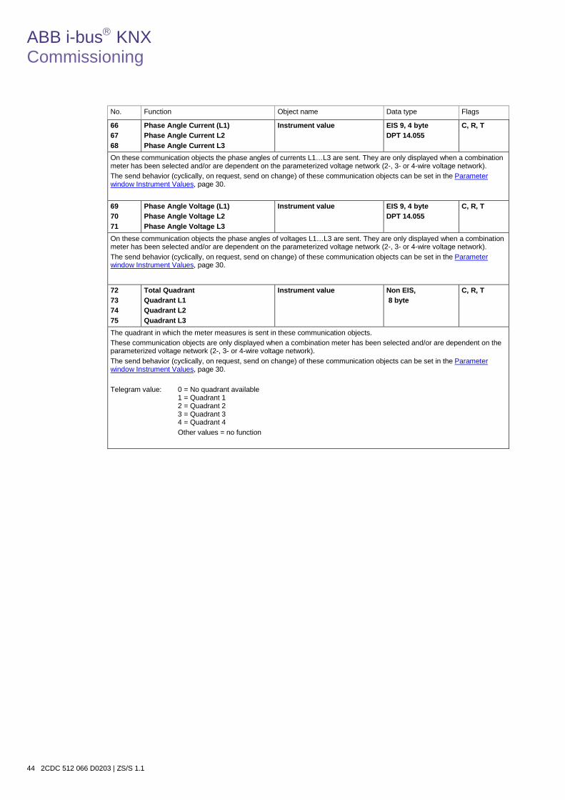
ABB i-bus KNX Commissioning
44 2CDC 512 066 D0203 | ZS/S 1.1
No. Function Object name Data type Flags
66 67 68
Phase Angle Current (L1) Phase Angle Current L2 Phase Angle Current L3
Instrument value EIS 9, 4 byte DPT 14.055
C, R, T
On these communication objects the phase angles of currents L1…L3 are sent. They are only displayed when a combination meter has been selected and/or are dependent on the parameterized voltage network (2-, 3- or 4-wire voltage network). The send behavior (cyclically, on request, send on change) of these communication objects can be set in the Parameter window Instrument Values, page 30. 69 70 71
Phase Angle Voltage (L1) Phase Angle Voltage L2 Phase Angle Voltage L3
Instrument value EIS 9, 4 byte DPT 14.055
C, R, T
On these communication objects the phase angles of voltages L1…L3 are sent. They are only displayed when a combination meter has been selected and/or are dependent on the parameterized voltage network (2-, 3- or 4-wire voltage network). The send behavior (cyclically, on request, send on change) of these communication objects can be set in the Parameter window Instrument Values, page 30.
72 73 74 75
Total Quadrant Quadrant L1 Quadrant L2 Quadrant L3
Instrument value Non EIS, 8 byte
C, R, T
The quadrant in which the meter measures is sent in these communication objects. These communication objects are only displayed when a combination meter has been selected and/or are dependent on the parameterized voltage network (2-, 3- or 4-wire voltage network). The send behavior (cyclically, on request, send on change) of these communication objects can be set in the Parameter window Instrument Values, page 30. Telegram value: 0 = No quadrant available
1 = Quadrant 1 2 = Quadrant 2 3 = Quadrant 3 4 = Quadrant 4 Other values = no function
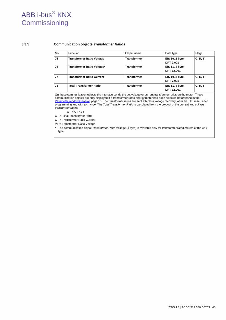
ABB i-bus KNX Commissioning
ZS/S 1.1 | 2CDC 512 066 D0203 45
3.3.5 Communication objects Transformer Ratios
No. Function Object name Data type Flags
76 76
Transformer Ratio Voltage Transformer Ratio Voltage*
Transformer Transformer
EIS 10, 2 byte DPT 7.001 EIS 11, 4 byte DPT 12.001
C, R, T
77 Transformer Ratio Current Transformer EIS 10, 2 byte DPT 7.001
C, R, T
78 Total Transformer Ratio Transformer EIS 11, 4 byte DPT 12.001
C, R, T
On these communication objects the interface sends the set voltage or current transformer ratios on the meter. These communication objects are only displayed if a transformer rated energy meter has been selected beforehand in the Parameter window General, page 16. The transformer ratios are sent after bus voltage recovery, after an ETS reset, after programming and with a change. The Total Transformer Ratio is calculated from the product of the current and voltage transformer ratios: GT = CT * VT GT = Total Transformer Ratio CT = Transformer Ratio Current VT = Transformer Ratio Voltage * The communication object Transformer Ratio Voltage (4 byte) is available only for transformer rated meters of the A4x
type.
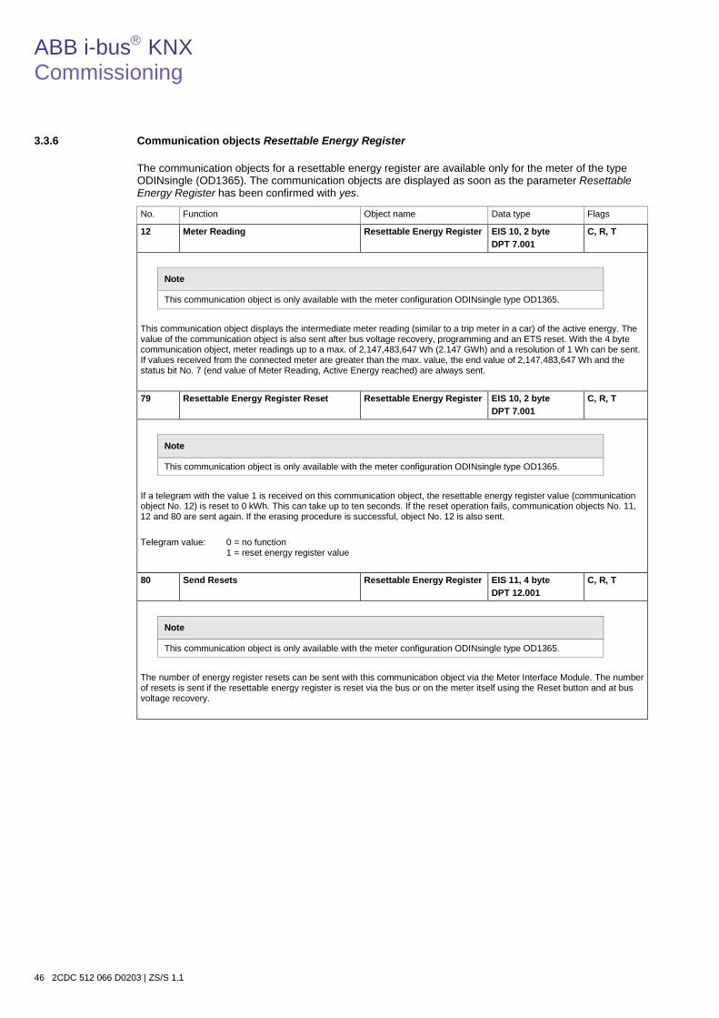
ABB i-bus KNX Commissioning
46 2CDC 512 066 D0203 | ZS/S 1.1
3.3.6 Communication objects Resettable Energy Register
The communication objects for a resettable energy register are available only for the meter of the type ODINsingle (OD1365). The communication objects are displayed as soon as the parameter Resettable Energy Register has been confirmed with yes.
No. Function Object name Data type Flags
12 Meter Reading Resettable Energy Register EIS 10, 2 byte DPT 7.001
C, R, T
Note
This communication object is only available with the meter configuration ODINsingle type OD1365.
This communication object displays the intermediate meter reading (similar to a trip meter in a car) of the active energy. The value of the communication object is also sent after bus voltage recovery, programming and an ETS reset. With the 4 byte communication object, meter readings up to a max. of 2,147,483,647 Wh (2.147 GWh) and a resolution of 1 Wh can be sent. If values received from the connected meter are greater than the max. value, the end value of 2,147,483,647 Wh and the status bit No. 7 (end value of Meter Reading, Active Energy reached) are always sent.
79 Resettable Energy Register Reset Resettable Energy Register EIS 10, 2 byte DPT 7.001
C, R, T
Note
This communication object is only available with the meter configuration ODINsingle type OD1365.
If a telegram with the value 1 is received on this communication object, the resettable energy register value (communication object No. 12) is reset to 0 kWh. This can take up to ten seconds. If the reset operation fails, communication objects No. 11, 12 and 80 are sent again. If the erasing procedure is successful, object No. 12 is also sent. Telegram value: 0 = no function
1 = reset energy register value 80 Send Resets Resettable Energy Register EIS 11, 4 byte
DPT 12.001 C, R, T
Note
This communication object is only available with the meter configuration ODINsingle type OD1365.
The number of energy register resets can be sent with this communication object via the Meter Interface Module. The number of resets is sent if the resettable energy register is reset via the bus or on the meter itself using the Reset button and at bus voltage recovery.
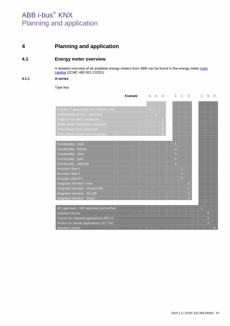
ABB i-bus KNX Planning and application
ZS/S 1.1 | 2CDC 512 066 D0203 47
4 Planning and application
4.1 Energy meter overview
A detailed overview of all available energy meters from ABB can be found in the energy meter main catalog (2CMC 480 001 C0201).
4.1.1 A-series
Type key
Example A 4 3 1 1 2 - 1 0 0
A-series (7 space units and 4 space units) A Hardware/electronics - advanced 4 Single phase direct connected 1 Single phase transformer connected 2 Three phase direct connected 3 Three phase transformer connected 4 Functionality - steel 1 Functionality - bronze 2 Functionality - silver 3 Functionality - gold 4 Functionality - platinum 5 Accuracy class 1 1 Accuracy class 2 2 Accuracy class 0.5 5 Integrated interface- none 0 Integrated interface - infrared (IR) 1 Integrated interface - RS-485 2 Integrated interface - M-bus 3 IEC approved + MID approved and verified 1 Standard version 0 Version for industrial applications (690 V) 1 Version for railway applications (16.7 Hz) 2 Standard version 0

ABB i-bus KNX Planning and application
48 2CDC 512 066 D0203 | ZS/S 1.1
4.1.1.1 Function overview
For simple selection of the right meter, various "metal colors" corresponding to the properties and functions are assigned to the energy meters from the A-series. They are described in the overview below.
Note
Time dependent functions (value/event memories, min./max. values, load profiles, harmonics measurement), pulse inputs/outputs and resettable energy registers cannot be read or controlled via Meter Interface Module ZS/S 1.1.

ABB i-bus KNX Planning and application
ZS/S 1.1 | 2CDC 512 066 D0203 49
Single phase meter 80 A, 4 DIN with IR port
Verified and approved according to MID
IEC approval
Direct connected electricity meter Functionality Voltage V Accuracy
class I/O Type Order code
Active import measurement Steel 57 … 288 V AC B (Cl. 1) Pulse output A41 111 - 100 2CMA170554R1000
Silver 57 … 288 V AC B (Cl. 1) 2 output, 2 input A41 311 - 100 2CMA170502R1000
Direct connected electricity meter, RS-485 Functionality Voltage V Accuracy
class I/O Type Order code
Active import measurement Steel 57 … 288 V AC B (Cl. 1) Pulse output A41 112 - 100 2CMA170500R1000
Active import and export measurement Bronze 57 … 288 V AC B (Cl. 1) Pulse output A41 212 - 100 2CMA170501R1000
Silver 57 … 288 V AC B (Cl. 1) 2 output, 2 input A41 312 - 100 2CMA170503R1000
Gold 57 … 288 V AC B (Ccl. 1) 2 output, 2 input A41 412 - 100 2CMA170505R1000
Direct connected electricity meter, M-bus Functionality Voltage V Accuracy
class I/O Type Order code
Active import and export measurement Silver 57 … 288 V AC B (Cl. 1) 2 output, 2 input A41 313 - 100 2CMA170504R1000
Gold 57 … 288 V AC B (Cl. 1) 2 output, 2 input A41 413 - 100 2CMA170506R1000
Active and reactive import and export measurement Platinum 57 … 288 V AC B (Cl. 1)
Reactive Cl. 2 Configurable A41 513 - 100 2CMA170508R1000

ABB i-bus KNX Planning and application
50 2CDC 512 066 D0203 | ZS/S 1.1
Single phase meter 6 A, 4 DIN with IR port
Verified and approved according to MID
IEC approval
CTVT connected electricity meter Functionality Voltage V Accuracy
class I/O Type Order code
Active import measurement Steel 57 … 288 V AC B (Cl. 1) Pulse output A42 111 - 100 2CMA170555R1000
CTVT connected electricity meter, RS-485 Functionality Voltage V Accuracy
class I/O Type Order code
Active import measurement Steel 57 … 288 V AC B (Cl. 1) Pulse output A42 112 - 100 2CMA170510R1000
Active import and export measurement Bronze 57 … 288 V AC B (Cl. 1) Pulse output A42 212 - 100 2CMA170511R1000
Silver 57 … 288 V AC B (Cl. 1) 2 output, 2 input A42 312 - 100 2CMA170512R1000
Gold 57 … 288 V AC B (Cl. 1) 2 output, 2 input A42 412 - 100 2CMA170513R1000
Active and reactive import and export measurement, 16.7 Hz Platinum 57 … 288 V AC C (Cl. 0.5)
Reactive Cl. 2 Configurable A42 552 - 120 2CMA170518R1000
CTVT connected electricity meter, M-bus Functionality Voltage V Accuracy
class I/O Type Order code
Active import and export measurement Gold 57 … 288 V AC B (Cl. 1) 2 output, 2 input A42 413 - 100 2CMA170514R1000
Active and reactive import and export measurement, 16.7 Hz
Platinum 57 … 288 V AC C (Cl. 0.5) Reactive Cl. 2
Configurable A42 553 - 120 2CMA170519R1000
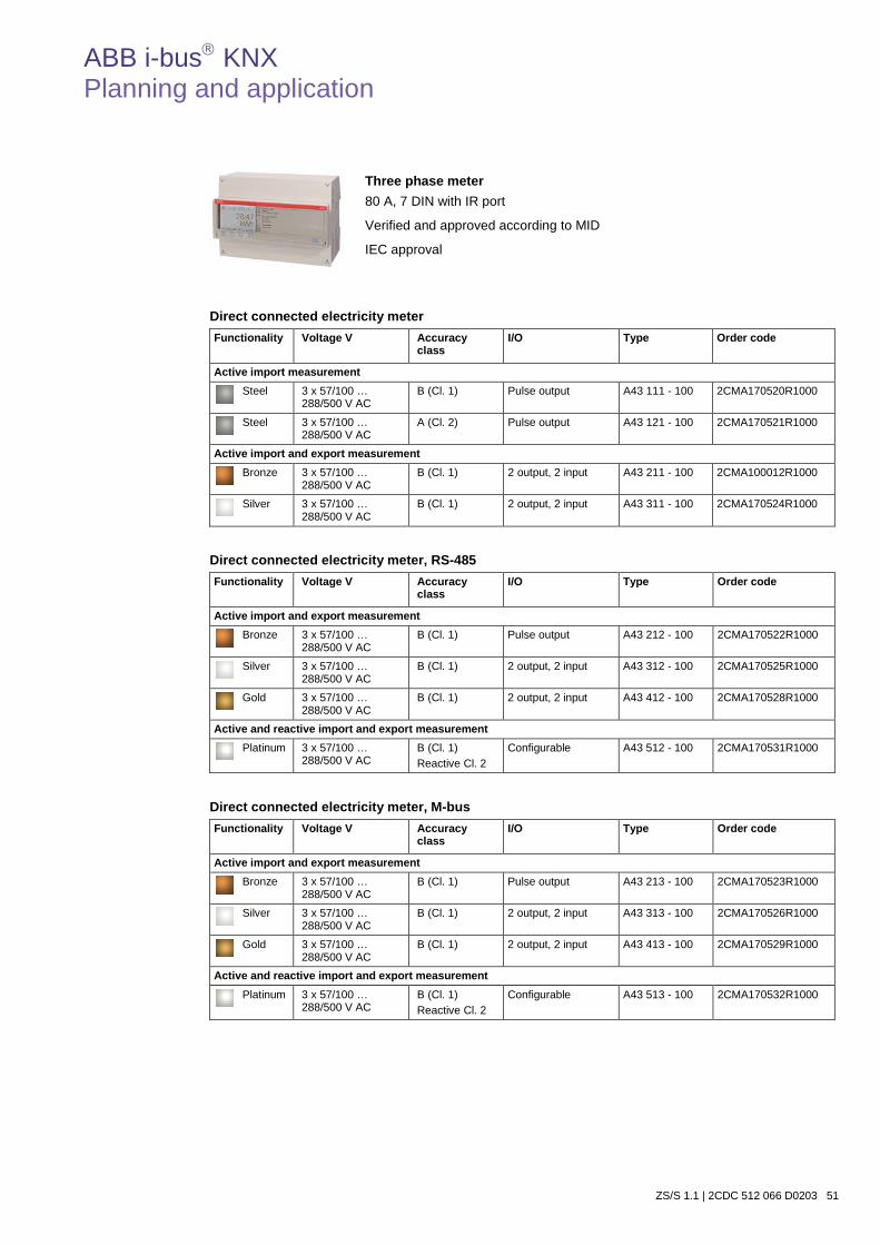
ABB i-bus KNX Planning and application
ZS/S 1.1 | 2CDC 512 066 D0203 51
Three phase meter 80 A, 7 DIN with IR port
Verified and approved according to MID
IEC approval
Direct connected electricity meter Functionality Voltage V Accuracy
class I/O Type Order code
Active import measurement Steel 3 x 57/100 …
288/500 V AC B (Cl. 1) Pulse output A43 111 - 100 2CMA170520R1000
Steel 3 x 57/100 … 288/500 V AC
A (Cl. 2) Pulse output A43 121 - 100 2CMA170521R1000
Active import and export measurement Bronze 3 x 57/100 …
288/500 V AC B (Cl. 1) 2 output, 2 input A43 211 - 100 2CMA100012R1000
Silver 3 x 57/100 … 288/500 V AC
B (Cl. 1) 2 output, 2 input A43 311 - 100 2CMA170524R1000
Direct connected electricity meter, RS-485 Functionality Voltage V Accuracy
class I/O Type Order code
Active import and export measurement Bronze 3 x 57/100 …
288/500 V AC B (Cl. 1) Pulse output A43 212 - 100 2CMA170522R1000
Silver 3 x 57/100 … 288/500 V AC
B (Cl. 1) 2 output, 2 input A43 312 - 100 2CMA170525R1000
Gold 3 x 57/100 … 288/500 V AC
B (Cl. 1) 2 output, 2 input A43 412 - 100 2CMA170528R1000
Active and reactive import and export measurement Platinum 3 x 57/100 …
288/500 V AC B (Cl. 1) Reactive Cl. 2
Configurable A43 512 - 100 2CMA170531R1000
Direct connected electricity meter, M-bus Functionality Voltage V Accuracy
class I/O Type Order code
Active import and export measurement Bronze 3 x 57/100 …
288/500 V AC B (Cl. 1) Pulse output A43 213 - 100 2CMA170523R1000
Silver 3 x 57/100 … 288/500 V AC
B (Cl. 1) 2 output, 2 input A43 313 - 100 2CMA170526R1000
Gold 3 x 57/100 … 288/500 V AC
B (Cl. 1) 2 output, 2 input A43 413 - 100 2CMA170529R1000
Active and reactive import and export measurement Platinum 3 x 57/100 …
288/500 V AC B (Cl. 1) Reactive Cl. 2
Configurable A43 513 - 100 2CMA170532R1000
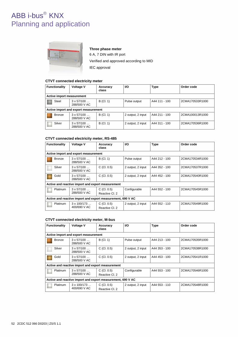
ABB i-bus KNX Planning and application
52 2CDC 512 066 D0203 | ZS/S 1.1
Three phase meter 6 A, 7 DIN with IR port
Verified and approved according to MID
IEC approval
CTVT connected electricity meter Functionality Voltage V Accuracy
class I/O Type Order code
Active import measurement Steel 3 x 57/100 …
288/500 V AC B (Cl. 1) Pulse output A44 111 - 100 2CMA170533R1000
Active import and export measurement Bronze 3 x 57/100 …
288/500 V AC B (Cl. 1) 2 output, 2 input A44 211 - 100 2CMA100013R1000
Silver 3 x 57/100 … 288/500 V AC
B (Cl. 1) 2 output, 2 input A44 311 - 100 2CMA170536R1000
CTVT connected electricity meter, RS-485 Functionality Voltage V Accuracy
class I/O Type Order code
Active import and export measurement Bronze 3 x 57/100 …
288/500 V AC B (Cl. 1) Pulse output A44 212 - 100 2CMA170534R1000
Silver 3 x 57/100 … 288/500 V AC
C (Cl. 0.5) 2 output, 2 input A44 352 - 100 2CMA170537R1000
Gold 3 x 57/100 … 288/500 V AC
C (Cl. 0.5) 2 output, 2 input A44 452 - 100 2CMA170540R1000
Active and reactive import and export measurement Platinum 3 x 57/100 …
288/500 V AC C (Cl. 0.5) Reactive Cl. 2
Configurable A44 552 - 100 2CMA170545R1000
Active and reactive import and export measurement, 690 V AC
Platinum 3 x 100/173 … 400/690 V AC
C (Cl. 0.5) Reactive Cl. 2
2 output, 2 input A44 552 - 110 2CMA170549R1000
CTVT connected electricity meter, M-bus Functionality Voltage V Accuracy
class I/O Type Order code
Active import and export measurement Bronze 3 x 57/100 …
288/500 V AC B (Cl. 1) Pulse output A44 213 - 100 2CMA170535R1000
Silver 3 x 57/100 … 288/500 V AC
C (Cl. 0.5) 2 output, 2 input A44 353 - 100 2CMA170538R1000
Gold 3 x 57/100 … 288/500 V AC
C (Cl. 0.5) 2 output, 2 input A44 453 - 100 2CMA170541R1000
Active and reactive import and export measurement Platinum 3 x 57/100 …
288/500 V AC C (Cl. 0.5) Reactive Cl. 2
Configurable A44 553 - 100 2CMA170546R1000
Active and reactive import and export measurement, 690 V AC
Platinum 3 x 100/173 … 400/690 V AC
C (Cl. 0.5) Reactive Cl. 2
2 output, 2 input A44 553 - 110 2CMA170548R1000
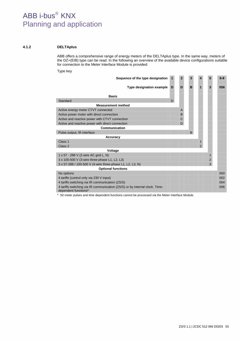
ABB i-bus KNX Planning and application
ZS/S 1.1 | 2CDC 512 066 D0203 53
4.1.2 DELTAplus
ABB offers a comprehensive range of energy meters of the DELTAplus type. In the same way, meters of the DZ+(EIB) type can be read. In the following an overview of the available device configurations suitable for connection to the Meter Interface Module is provided:
Type key
Sequence of the type designation 1 2 3 4 5 6-8
Type designation example D D B 1 3 056
Basis Standard D
Measurement method Active energy meter CTVT connected A Active power meter with direct connection B Active and reactive power with CTVT connection C Active and reactive power with direct connection D
Communication Pulse output, IR interface B
Accuracy Class 1 1 Class 2 2
Voltage 1 x 57 - 288 V (2-wire AC grid L, N) 1 3 x 100-500 V (3-wire three-phase L1, L2, L3) 2 3 x 57-288 / 100-500 V (4-wire three-phase L1, L2, L3, N) 3
Optional functions No options 000 4 tariffs (control only via 230 V input) 002 4 tariffs switching via IR communication (ZS/S) 004 4 tariffs switching via IR communication (ZS/S) or by internal clock. Time-dependent functions*
006
* S0 meter pulses and time dependent functions cannot be processed via the Meter Interface Module.
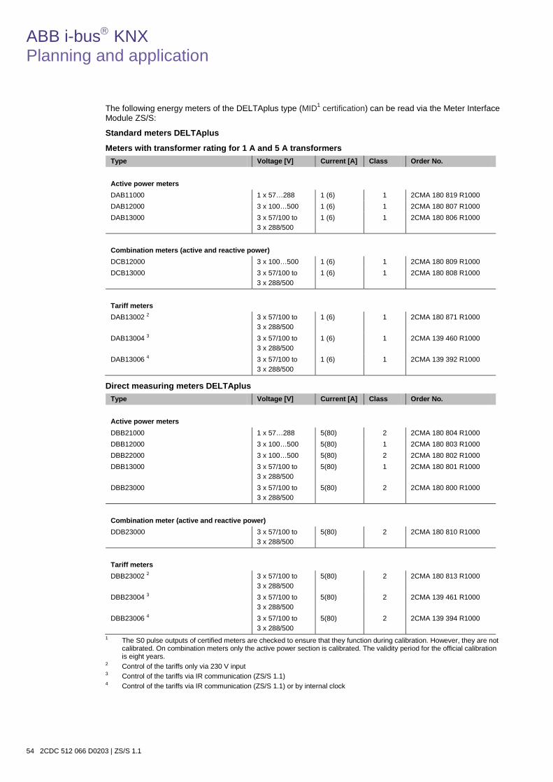
ABB i-bus KNX Planning and application
54 2CDC 512 066 D0203 | ZS/S 1.1
The following energy meters of the DELTAplus type (MID1 certification) can be read via the Meter Interface Module ZS/S:
Standard meters DELTAplus
Meters with transformer rating for 1 A and 5 A transformers Type Voltage [V] Current [A] Class Order No. Active power meters DAB11000 1 x 57…288 1 (6) 1 2CMA 180 819 R1000 DAB12000 3 x 100…500 1 (6) 1 2CMA 180 807 R1000 DAB13000 3 x 57/100 to
3 x 288/500 1 (6) 1 2CMA 180 806 R1000
Combination meters (active and reactive power) DCB12000 3 x 100…500 1 (6) 1 2CMA 180 809 R1000 DCB13000 3 x 57/100 to
3 x 288/500 1 (6) 1 2CMA 180 808 R1000
Tariff meters DAB13002 2
3 x 57/100 to 3 x 288/500
1 (6) 1 2CMA 180 871 R1000
DAB13004 3
3 x 57/100 to 3 x 288/500
1 (6) 1 2CMA 139 460 R1000
DAB13006 4 3 x 57/100 to 3 x 288/500
1 (6) 1 2CMA 139 392 R1000
Direct measuring meters DELTAplus Type Voltage [V] Current [A] Class Order No. Active power meters DBB21000 1 x 57…288 5(80) 2 2CMA 180 804 R1000 DBB12000 3 x 100…500 5(80) 1 2CMA 180 803 R1000 DBB22000 3 x 100…500 5(80) 2 2CMA 180 802 R1000 DBB13000 3 x 57/100 to
3 x 288/500 5(80) 1 2CMA 180 801 R1000
DBB23000 3 x 57/100 to 3 x 288/500
5(80) 2 2CMA 180 800 R1000
Combination meter (active and reactive power) DDB23000 3 x 57/100 to
3 x 288/500 5(80) 2 2CMA 180 810 R1000
Tariff meters DBB23002 2
3 x 57/100 to 3 x 288/500
5(80) 2 2CMA 180 813 R1000
DBB23004 3
3 x 57/100 to 3 x 288/500
5(80) 2 2CMA 139 461 R1000
DBB23006 4 3 x 57/100 to 3 x 288/500
5(80) 2 2CMA 139 394 R1000
1 The S0 pulse outputs of certified meters are checked to ensure that they function during calibration. However, they are not calibrated. On combination meters only the active power section is calibrated. The validity period for the official calibration is eight years.
2 Control of the tariffs only via 230 V input 3 Control of the tariffs via IR communication (ZS/S 1.1) 4 Control of the tariffs via IR communication (ZS/S 1.1) or by internal clock
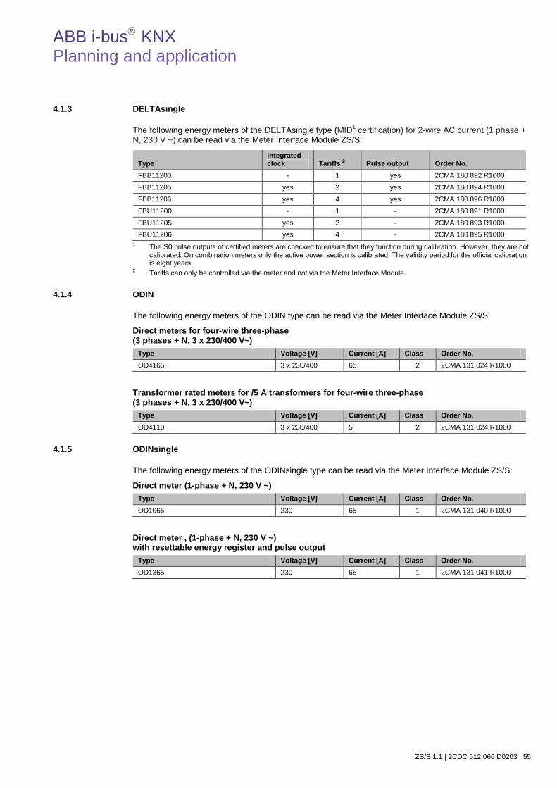
ABB i-bus KNX Planning and application
ZS/S 1.1 | 2CDC 512 066 D0203 55
4.1.3 DELTAsingle
The following energy meters of the DELTAsingle type (MID1 certification) for 2-wire AC current (1 phase + N, 230 V ~) can be read via the Meter Interface Module ZS/S:
Type Integrated clock Tariffs 2 Pulse output Order No.
FBB11200 - 1 yes 2CMA 180 892 R1000
FBB11205 yes 2 yes 2CMA 180 894 R1000
FBB11206 yes 4 yes 2CMA 180 896 R1000
FBU11200 - 1 - 2CMA 180 891 R1000
FBU11205 yes 2 - 2CMA 180 893 R1000
FBU11206 yes 4 - 2CMA 180 895 R1000 1 The S0 pulse outputs of certified meters are checked to ensure that they function during calibration. However, they are not
calibrated. On combination meters only the active power section is calibrated. The validity period for the official calibration is eight years.
2 Tariffs can only be controlled via the meter and not via the Meter Interface Module.
4.1.4 ODIN
The following energy meters of the ODIN type can be read via the Meter Interface Module ZS/S:
Direct meters for four-wire three-phase (3 phases + N, 3 x 230/400 V~)
Type Voltage [V] Current [A] Class Order No. OD4165 3 x 230/400 65 2 2CMA 131 024 R1000
Transformer rated meters for /5 A transformers for four-wire three-phase (3 phases + N, 3 x 230/400 V~)
Type Voltage [V] Current [A] Class Order No. OD4110 3 x 230/400 5 2 2CMA 131 024 R1000
4.1.5 ODINsingle
The following energy meters of the ODINsingle type can be read via the Meter Interface Module ZS/S:
Direct meter (1-phase + N, 230 V ~) Type Voltage [V] Current [A] Class Order No. OD1065 230 65 1 2CMA 131 040 R1000
Direct meter , (1-phase + N, 230 V ~) with resettable energy register and pulse output
Type Voltage [V] Current [A] Class Order No. OD1365 230 65 1 2CMA 131 041 R1000

ABB i-bus KNX Planning and application
56 2CDC 512 066 D0203 | ZS/S 1.1
4.2 Behavior after bus voltage recovery, download and ETS reset
Bus voltage recovery*
(BW) Behavior after programming
ETS reset Reset device
Sending delay Active, if parameterized Active, if parameterized Active, if parameterized
Meter reading 1 Active / reactive energy (Tariffs 1 -4, total)
Momentary meter reading (or meter reading tariff X and meter reading total) is sent
Momentary meter reading (or meter reading tariff X and meter reading total) is sent
Momentary meter reading (or meter reading tariff X and meter reading total) is sent
Power values 2
Pactive, Preactive, Papparent,
phase angle, power factor
Are sent as soon as the change value under parameter Send power values on change is ≥ ±1
Are sent as soon as the change value under parameter Send power values on change is ≥ ±1
Are sent as soon as the change value under parameter Send power values on change is ≥ 1
Instrument values 2 Current, voltage, frequency, phase angle (I, U)
Are sent as soon as the change value under parameter Send instrument values on change ≥ 1
Are sent as soon as the change value under parameter Send instrument values on change ≥ 1
Are sent as soon as the change value under parameter Send instrument values on change ≥ 1
Current tariff 3 Is sent Is sent Is sent
Transformer ratio 4 Current, voltage, total
Is sent Is sent Is sent
Power failures 3 Are sent Are sent Are sent
Status byte Is sent Is sent Is sent
Error message Is sent Is sent Is sent
Meter type Is sent Is sent Is sent 1 The meter reading of the reactive energy or meter reading total/tariffs 1-4 to be sent is dependent on the parameterized
energy meter (meter type, configuration, tariffs). 2 Power and instrument values are sent depending on the parameterized configuration of the meter of type A4x or
DELTAplus. 3 Tariffs and power failures are not sent by energy meters of the ODIN type. 4 Transformer ratios can only be sent with meters of the type A4x or DELTAplus and ODIN.
Note
* We recommend the use of an Uninterruptible Power Supply such as the SU/S 30.640.1, to avoid brief failures of the bus voltage.
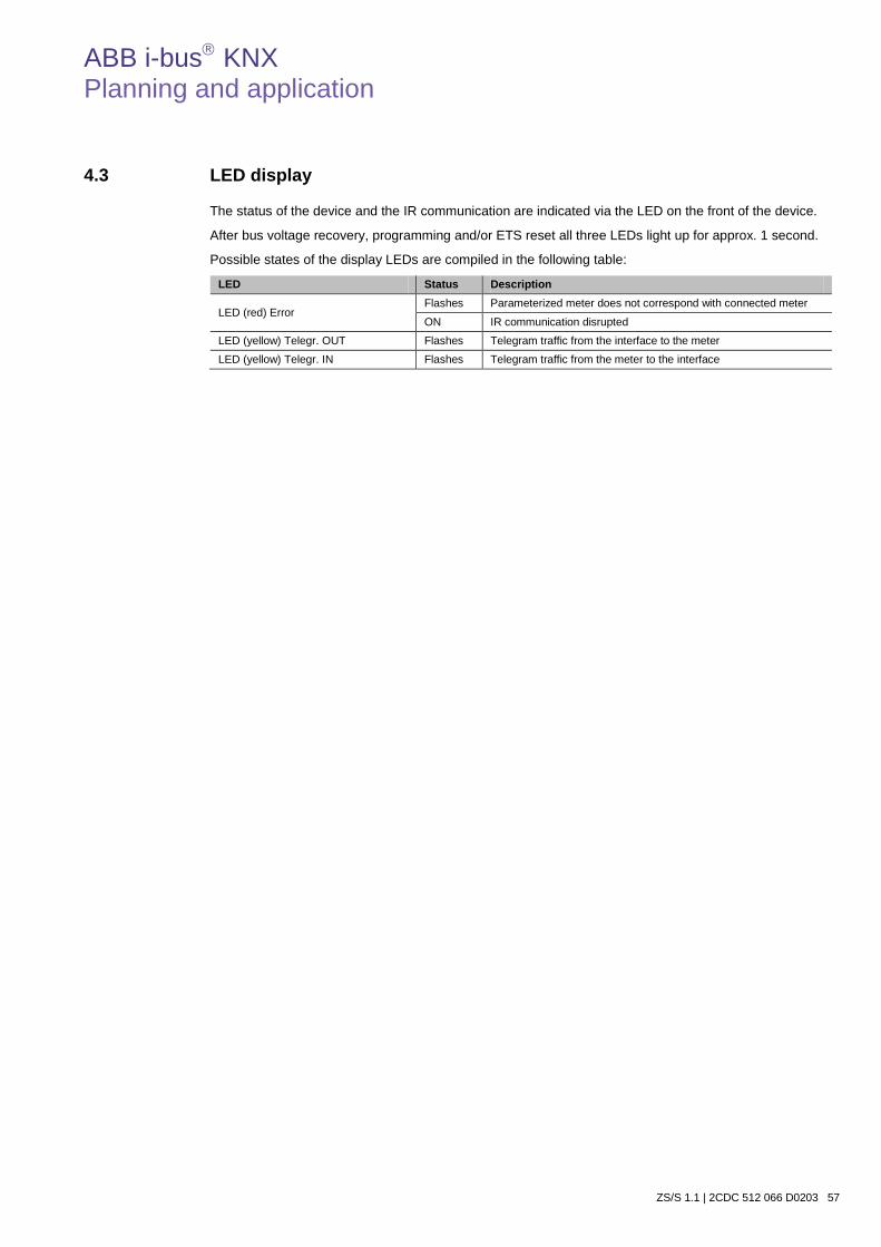
ABB i-bus KNX Planning and application
ZS/S 1.1 | 2CDC 512 066 D0203 57
4.3 LED display
The status of the device and the IR communication are indicated via the LED on the front of the device.
After bus voltage recovery, programming and/or ETS reset all three LEDs light up for approx. 1 second.
Possible states of the display LEDs are compiled in the following table:
LED Status Description
LED (red) Error Flashes Parameterized meter does not correspond with connected meter
ON IR communication disrupted
LED (yellow) Telegr. OUT Flashes Telegram traffic from the interface to the meter
LED (yellow) Telegr. IN Flashes Telegram traffic from the meter to the interface

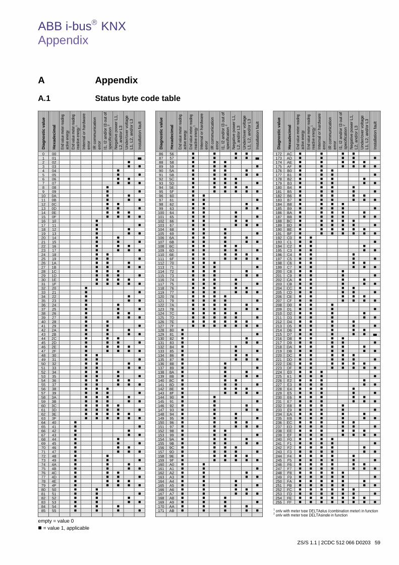
ABB i-bus KNX Appendix
ZS/S 1.1 | 2CDC 512 066 D0203 59
A Appendix
A.1 Status byte code table
empty = value 0 = value 1, applicable
Dia
gnos
tic v
alue
Hex
adec
imal
End v
alue
meter
read
ing
activ
e en
ergy
En
d valu
e me
ter re
ading
re
activ
e ene
rgy 1
Inte
rnal
or h
ardw
are
erro
r IR
com
mun
icat
ion
erro
r I1
, I2
and/
or I3
out
of
spec
ifica
tion
2 N
egat
ive
pow
er L
1,
L2, a
nd/o
r L3
Und
er/o
ver v
olta
ge
L1, L
2, a
nd/o
r L3
Inst
alla
tion
faul
t
0 00 86 56 172 AC 1 01 87 57 173 AD 2 02 88 58 174 AE 3 03 89 59 175 AF 4 04 90 5A 176 B0 5 05 91 5B 177 B1 6 06 92 5C 178 B2 7 07 93 5D 179 B3 8 08 94 5E 180 B4 9 09 95 5F 181 B5
10 0A 96 60 182 B6 11 0B 97 61 183 B7 12 0C 98 62 184 B8 13 0D 99 63 185 B9 14 0E 100 64 186 BA 15 0F 101 65 187 BB 16 10 102 66 188 BC 17 11 103 67 189 BD 18 12 104 68 190 BE 19 13 105 69 191 BF 20 14 106 6A 192 C0 21 15 107 6B 193 C1 22 16 108 6C 194 C2 23 17 109 6D 195 C3 24 18 110 6E 196 C4 25 19 111 6F 197 C5 26 1A 112 70 198 C6 27 1B 113 71 199 C7 28 1C 114 72 200 C8 29 1D 115 73 201 C9 30 1E 116 74 202 CA 31 1F 117 75 203 CB 32 20 118 76 204 CC 33 21 119 77 205 CD 34 22 120 78 206 CE 35 23 121 79 207 CF 36 24 122 7A 208 D0 37 25 123 7B 209 D1 38 26 124 7C 210 D2 39 27 125 7D 211 D3 40 28 126 7E 212 D4 41 29 127 7F 213 D5 42 2A 128 80 214 D6 43 2B 129 81 215 D7 44 2C 130 82 216 D8 45 2D 131 83 217 D9 46 2E 132 84 218 DA 47 2F 133 85 219 DB 48 30 134 86 220 DC 49 31 135 87 221 DD 50 32 136 88 222 DE 51 33 137 89 223 DF 52 34 138 8A 224 E0 53 35 139 8B 225 E1 54 36 140 8C 226 E2 55 37 141 8D 227 E3 56 38 142 8E 228 E4 57 39 143 8F 229 E5 58 3A 144 90 230 E6 59 3B 145 91 231 E7 60 3C 146 92 232 E8 61 3D 147 93 233 E9 62 3E 148 94 234 EA 63 3F 149 95 235 EB 64 40 150 96 236 EC 65 41 151 97 237 ED 66 42 152 98 238 EE 67 43 153 99 239 EF 68 44 154 9A 240 F0 69 45 155 9B 241 F1 70 46 156 9C 242 F2 71 47 157 9D 243 F3 72 48 158 9E 244 F4 73 49 159 9F 245 F5 74 4A 160 A0 246 F6 75 4B 161 A1 247 F7 76 4C 162 A2 248 F8 77 4D 163 A3 249 F9 78 4E 164 A4 250 FA 79 4F 165 A5 251 FB 80 50 166 A6 252 FC 81 51 167 A7 253 FD 82 52 168 A8 254 FE 83 53 169 A9 255 FF 84 54 170 AA 85 55 171 AB 1 only with meter type DELTAplus (combination meter) in function
2 only with meter type DELTAsingle in function
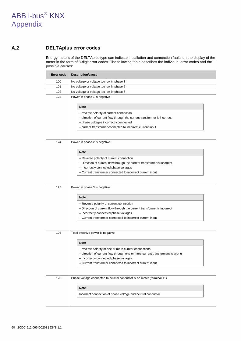
ABB i-bus KNX Appendix
60 2CDC 512 066 D0203 | ZS/S 1.1
A.2 DELTAplus error codes
Energy meters of the DELTAplus type can indicate installation and connection faults on the display of the meter in the form of 3-digit error codes. The following table describes the individual error codes and the possible causes:
Error code Description/cause
100 No voltage or voltage too low in phase 1
101 No voltage or voltage too low in phase 2
102 No voltage or voltage too low in phase 3
123 Power in phase 1 is negative
Note
– reverse polarity of current connection – direction of current flow through the current transformer is incorrect – phase voltages incorrectly connected – current transformer connected to incorrect current input
124 Power in phase 2 is negative
Note
– Reverse polarity of current connection – Direction of current flow through the current transformer is incorrect – Incorrectly connected phase voltages – Current transformer connected to incorrect current input
125 Power in phase 3 is negative
Note
– Reverse polarity of current connection – Direction of current flow through the current transformer is incorrect – Incorrectly connected phase voltages – Current transformer connected to incorrect current input
126 Total effective power is negative
Note
– reverse polarity of one or more current connections – direction of current flow through one or more current transformers is wrong – Incorrectly connected phase voltages – Current transformer connected to incorrect current input
128 Phase voltage connected to neutral conductor N on meter (terminal 11)
Note
Incorrect connection of phase voltage and neutral conductor

ABB i-bus KNX Appendix
ZS/S 1.1 | 2CDC 512 066 D0203 61
A.3 DELTAsingle error codes
Energy meters of the DELTAsingle type can indicate installation and connection faults on the display of the meter in the form of 3-digit error codes. The following table describes the individual error codes and the possible causes:
Error code Description/cause
100 101 102 103 104 105 106 107
Checksum error tariff 1, active energy Checksum error tariff 2, active energy Checksum error tariff 3, active energy Checksum error tariff 4, active energy Checksum error total active energy Checksum error monthly values, active energy Checksum error Checksum error
200 201 202 203 204 205
Checksum error tariff 1, reactive energy Checksum error tariff 2, reactive energy Checksum error tariff 3, reactive energy Checksum error tariff 4, reactive energy Checksum error total, reactive energy Checksum error monthly values, reactive energy
300 301 302 303 304 305 306 307
Voltage U1, U2 or U3 too high (above meter specification range) Voltage U1, U2 or U3 too low (under meter specification range) Current I1, I2 or I3 too high (above meter specification range) Frequency out of meter specification U1 missing U2 missing U3 missing Phase connected to neutral conductor
400 401 402 403 404
Negative power phase 1 Negative power phase 2 Negative power phase 3 Total negative power External data signal on input out of specification
500 501 502 503
Pulse overlay Date not set Time not set Tariffs incorrectly set
600 601 602 603 604
Single phase meter Two phase meter Three phase meter Active energy Reactive energy
700 701 702 703 704
EEPROM failure Extended EEPROM failure Vref is not VDD/2 Temperature sensor error Clock error (RTC)
800 - 807 Internal error (for ABB use only)

ABB i-bus KNX Appendix
62 2CDC 512 066 D0203 | ZS/S 1.1
A.4 Energy measurement
A.4.1 Measurement fundamentals
Different measurement methods are employed on energy meters depending on the type selected. The following equations are vector equations.
Measurement process with one measuring element This method only produces the correct result when the phase loading is symmetrical (balanced).
P = 3 · IL3 · UL3 This method is not suitable for exact measurements in three-phase networks, as a 100 % symmetrical load is generally very seldom.
Measurement process with 2 measuring elements This method is used in three-phase networks without a neutral conductor (three conductor network) with the same or any load.
P = UL1 · IL1 + UL2 · IL2 + UL3 · IL3 ΣI = IL1 + IL2 + IL3 = 0 P = UL1 · IL1 - UL2 (IL1+ IL3) + UL3 · IL3 P = IL1(UL1 - L2) + IL3(UL3 - L2)
This measurement process (with 2 measuring elements) is not suitable for very accurate measurements in networks with inductive or capacitive loads with a low cos φ. In these cases, a measurement process with three measuring elements should be selected.
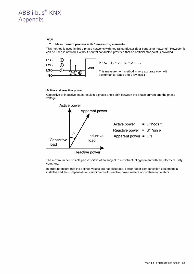
ABB i-bus KNX Appendix
ZS/S 1.1 | 2CDC 512 066 D0203 63
Measurement process with 3 measuring elements This method is used in three-phase networks with neutral conductor (four-conductor networks). However, it can be used in networks without neutral conductor, provided that an artificial star point is provided.
P = UL1 · IL1 + UL2 · IL2 + UL3 · IL3 This measurement method is very accurate even with asymmetrical loads and a low cos φ.
Active and reactive power Capacitive or inductive loads result in a phase angle shift between the phase current and the phase voltage.
The maximum permissible phase shift is often subject to a contractual agreement with the electrical utility company.
In order to ensure that the defined values are not exceeded, power factor compensation equipment is installed and the compensation is monitored with reactive power meters or combination meters.
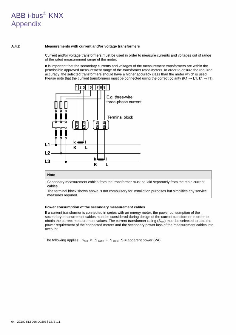
ABB i-bus KNX Appendix
64 2CDC 512 066 D0203 | ZS/S 1.1
A.4.2 Measurements with current and/or voltage transformers
Current and/or voltage transformers must be used in order to measure currents and voltages out of range of the rated measurement range of the meter.
It is important that the secondary currents and voltages of the measurement transformers are within the permissible approved measurement range of the transformer rated meters. In order to ensure the required accuracy, the selected transformers should have a higher accuracy class than the meter which is used. Please note that the current transformers must be connected using the correct polarity (K1 → L1, k1 → l1).
Note
Secondary measurement cables from the transformer must be laid separately from the main current cables. The terminal block shown above is not compulsory for installation purposes but simplifies any service measures required.
Power consumption of the secondary measurement cables If a current transformer is connected in series with an energy meter, the power consumption of the secondary measurement cables must be considered during design of the current transformer in order to obtain the correct measurement values. The current transformer rating (Ssec) must be selected to take the power requirement of the connected meters and the secondary power loss of the measurement cables into account.
The following applies: Ssec � S cable + S meter S = apparent power (VA)

ABB i-bus KNX Appendix
ZS/S 1.1 | 2CDC 512 066 D0203 65
The table of reference values below presents the cable power loss (S cable) as a function of the cable length and cross-section.
Secondary current
A
Cross- section
mm2
Cable power loss (VA) Cable length (input/output cable)
1 m 2 m 5 m 10 m 20 m 50 m 100 m
1 A 1.0 0.04 0.07 0.18 0.36 0.71 1.78 3.57 1 A 2.5 0.01 0.03 0.07 0.14 0.29 0.72 1.43 1 A 4.0 – – – 0.09 0.18 0.45 0.89
5 A 2.5 0.36 0.71 1.78 3.57 7.10 17.8 – 5 A 4.0 0.22 0.45 1.12 2.24 4.50 11.2 22.4 5 A 6.0 0.15 0.30 0.74 1.49 3.00 7.40 14.9
Energy summation If the energy of several loads is to be measured using a single energy meter, the individual cables of assigned current transformers must be connected in parallel. All the current transformers used must have identical transformer ratios, and the sum of the currents may not exceed 6 A. In the example shown (3-wire network) the meter measures the sum of the energy consumption of cable 1 and cable 2. The type of load (asymmetrical or symmetrical) is irrelevant in this case.
The same application is possible in a 4-wire network. Current transformers are then required in L1, L2 and L3. Please note that the current transformers must be connected using the correct polarity (K1 → L1, k1 → l1).
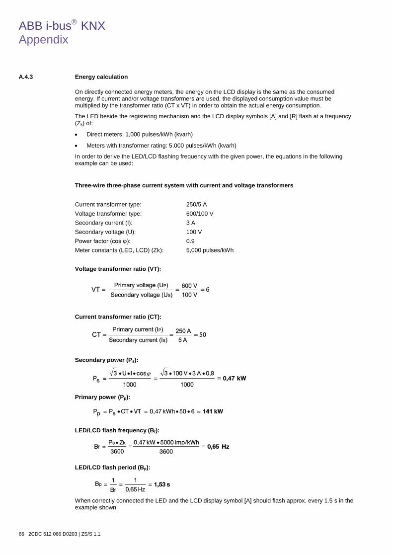
ABB i-bus KNX Appendix
66 2CDC 512 066 D0203 | ZS/S 1.1
A.4.3 Energy calculation
On directly connected energy meters, the energy on the LCD display is the same as the consumed energy. If current and/or voltage transformers are used, the displayed consumption value must be multiplied by the transformer ratio (CT x VT) in order to obtain the actual energy consumption.
The LED beside the registering mechanism and the LCD display symbols [A] and [R] flash at a frequency (Zk) of:
• Direct meters: 1,000 pulses/kWh (kvarh)
• Meters with transformer rating: 5,000 pulses/kWh (kvarh)
In order to derive the LED/LCD flashing frequency with the given power, the equations in the following example can be used:
Three-wire three-phase current system with current and voltage transformers
Current transformer type: 250/5 A Voltage transformer type: 600/100 V Secondary current (I): 3 A Secondary voltage (U): 100 V Power factor (cos φ): 0.9 Meter constants (LED, LCD) (Zk): 5,000 pulses/kWh
Voltage transformer ratio (VT):
Current transformer ratio (CT):
Secondary power (Ps):
Primary power (Pp):
LED/LCD flash frequency (Bf):
LED/LCD flash period (Bp):
When correctly connected the LED and the LCD display symbol [A] should flash approx. every 1.5 s in the example shown.

ABB i-bus KNX Appendix
ZS/S 1.1 | 2CDC 512 066 D0203 67
A.5 Ordering Information
Short description Description Order No. bbn 40 16779 EAN
Price group
Unit weight 1 pc. [kg]
Packaging [pc]
ZS/S 1.1 Meter Interface Module, MDRC 2CDG 110 083 R0011 66207 9 26 0.1 1

ABB i-bus KNX Appendix
68 2CDC 512 066 D0203 | ZS/S 1.1
Notes


Ord
er n
umbe
r 2C
DC
512
066
D02
03 (0
9.12
)
Contact
ABB STOTZ-KONTAKT GmbH Eppelheimer Straße 82 69123 Heidelberg, Germany Phone: +49 (0)6221 701 607 (Marketing) Fax: +49 (0)6221 701 724 E-mail: [email protected] Additional information and contact partners: www.abb.com/knx
Note: We reserve the right to make technical changes or modify the contents of this document without prior notice. With regard to purchase orders, the agreed particulars shall prevail. ABB AG does not accept any responsibility whatsoever for potential errors or possible lack of information in this document. We reserve all rights in this document and in the subject matter and illustrations contained therein. Any reproduction, disclosure to third parties or utilization of its contents – in whole or in parts – is forbidden without prior written consent of ABB AG. Copyright© 2012 ABB All rights reserved