Embed Size (px)
Citation preview

ABB industrial drives
Hardware manualACQ810-04 drive modules (1.1…45 kW, 1…60 hp)

List of related manuals
1) Delivered in PDF format on a manuals CD with the drive module.2) Delivered as a printed copy with the drive or optional equipment.All manuals are available in PDF format on the Internet. See section Document library on the Internet on the inside of the back cover.
Drive hardware manuals and guides Code (English)ACQ810-04 drive modules (1.1…45 kW, 1…60 hp) hardware manual
3AUA0000055160 1)
Drive firmware manuals and guidesACQ810-04 drive modules start-up guide 3AUA0000055159 2)
ACQ810 standard pump control program firmware manual
3AUA0000055144 1)
Option manuals and guidesACS-CP-U control panel IP54 mounting platform kit (+J410) installation guide
3AUA0000049072 2)
Manuals and quick guides for I/O extension modules, fieldbus adapters, etc.
2)
Hardware manualACQ810-04 drive modules (1.1…45 kW, 1…60 hp)
3AUA0000055160 Rev AEN
EFFECTIVE: 2009-09-18
© 2009 ABB Oy. All Rights Reserved.
1. Safety instructions
Table of contents
5. Mechanical installation
7. Electrical installation


Safety instructions 5
Safety instructions
What this chapter containsThis chapter contains the safety instructions which you must follow when installing, operating and servicing the drive. If ignored, physical injury or death may follow, or damage may occur to the drive, the motor, or driven equipment. Read the safety instructions before you work on the unit.
Use of warnings and notesThere are four types of safety instructions used in this manual:
Dangerous voltage warning warns of high voltage which can cause physical injury and/or damage to the equipment.
General warning warns about conditions, other than those caused by electricity, which can result in physical injury and/or damage to the equipment.
Electrostatic discharge warning warns of electrostatic discharge which can damage the equipment.
Hot surface warning warns of component surfaces that may become hot enough to cause burns if touched.

6 Safety instructions
Installation and maintenance workThese warnings are intended for all who work on the drive, motor cable or motor.
WARNING! Ignoring the following instructions can cause physical injury or death, or damage to the equipment.
Only qualified electricians are allowed to install and maintain the drive.
• Never work on the drive, the motor cable or the motor when input power is applied. After disconnecting the input power, always wait for 5 minutes to let the intermediate circuit capacitors discharge before you start working on the drive, the motor or the motor cable. Always ensure by measuring with a multimeter (impedance at least 1 Mohm) that:1. There is no voltage between the drive input phases U1, V1 and W1 and the ground.2. There is no voltage between terminals UDC+ and UDC– and the ground.3. There is no voltage between terminals R+ and R– and the ground.
• Do not work on the control cables when power is applied to the drive or to the external control circuits. Externally supplied control circuits may carry dangerous voltages even when the input power of the drive is switched off.
• Do not make any insulation or voltage withstand tests on the drive.
• If a drive whose varistors or internal EMC filters are not disconnected is installed on an IT power system (an ungrounded power system or a high resistance grounded [over 30 ohms] power system), the drive will be connected to earth potential through the varistors/filters. This may cause danger or damage the drive.
• If a drive whose varistors or internal EMC filter are not disconnected is installed on a corner-grounded TN system, the drive will be damaged.
Notes:
• Even when the motor is stopped, dangerous voltages are present at the power circuit terminals U1, V1, W1 and U2, V2, W2, and UDC+, UDC–, R+, R–.
• Depending on the external wiring, dangerous voltages (115 V, 220 V or 230 V) may be present on the terminals of the relay outputs of the drive.
• The drive supports the Safe torque off function. See page 40.
WARNING! Ignoring the following instructions can cause physical injury or death, or damage to the equipment.
• The drive is not field repairable. Never attempt to repair a malfunctioning drive; contact your local ABB representative or Authorized Service Center.
• Make sure that dust from drilling does not enter the drive during the installation. Electrically conductive dust inside the drive may cause damage or lead to malfunction.

Safety instructions 7
Start-up and operationThese warnings are intended for all who plan the operation of the drive, start up or operate the drive.
• Ensure sufficient cooling.
WARNING! The printed circuit boards contain components sensitive to electrostatic discharge. Wear a grounding wrist band when handling the boards. Do not touch the boards unnecessarily.
WARNING! Ignoring the following instructions can cause physical injury or death, or damage to the equipment.
• Before adjusting the drive and putting it into service, make sure that the motor and all driven equipment are suitable for operation throughout the speed range provided by the drive. The drive can be adjusted to operate the motor at speeds above and below the speed provided by connecting the motor directly to the power line.
• Do not activate automatic fault reset functions if dangerous situations can occur. When activated, these functions will reset the drive and resume operation after a fault.
• Do not control the motor with an AC contactor or disconnecting device (disconnecting means); instead, use the control panel or external commands via the I/O board of the drive or a fieldbus adapter. The maximum allowed number of charging cycles of the DC capacitors (i.e. power-ups by applying power) is one per two minutes. The maximum total number of chargings is 100000 for frame sizes A and B, 50000 for frame sizes C and D.
Notes:
• If an external source for start command is selected and it is ON, the drive will start immediately after an input voltage break or a fault reset unless the drive is configured for 3-wire (pulse) start/stop.
• When the control location is not set to local, the stop key on the control panel will not stop the drive.
WARNING! The surfaces of drive system components (such as the mains choke) may become hot when the system is in use.
8 Safety instructions
Table of contents 9
Table of contentsList of related manuals . . . . . . . . . . . . . . . . . . . . . . . . . . . . . . . . . . . . . . . . . . . . . . . . . . . . . . . 2
1. Safety instructionsWhat this chapter contains . . . . . . . . . . . . . . . . . . . . . . . . . . . . . . . . . . . . . . . . . . . . . . . . . . . . 5Use of warnings and notes . . . . . . . . . . . . . . . . . . . . . . . . . . . . . . . . . . . . . . . . . . . . . . . . . . . . 5Installation and maintenance work . . . . . . . . . . . . . . . . . . . . . . . . . . . . . . . . . . . . . . . . . . . . . . 6Start-up and operation . . . . . . . . . . . . . . . . . . . . . . . . . . . . . . . . . . . . . . . . . . . . . . . . . . . . . . . . 7
2. About this manualWhat this chapter contains . . . . . . . . . . . . . . . . . . . . . . . . . . . . . . . . . . . . . . . . . . . . . . . . . . . 15Compatibility . . . . . . . . . . . . . . . . . . . . . . . . . . . . . . . . . . . . . . . . . . . . . . . . . . . . . . . . . . . . . . 15Intended audience . . . . . . . . . . . . . . . . . . . . . . . . . . . . . . . . . . . . . . . . . . . . . . . . . . . . . . . . . . 15Categorization according to the frame size . . . . . . . . . . . . . . . . . . . . . . . . . . . . . . . . . . . . . . . 15Categorization according to the + code . . . . . . . . . . . . . . . . . . . . . . . . . . . . . . . . . . . . . . . . . . 16Contents . . . . . . . . . . . . . . . . . . . . . . . . . . . . . . . . . . . . . . . . . . . . . . . . . . . . . . . . . . . . . . . . . 16Installation and commissioning flowchart . . . . . . . . . . . . . . . . . . . . . . . . . . . . . . . . . . . . . . . . 17Terms and abbreviations . . . . . . . . . . . . . . . . . . . . . . . . . . . . . . . . . . . . . . . . . . . . . . . . . . . . . 19
3. Operation principle and hardware descriptionWhat this chapter contains . . . . . . . . . . . . . . . . . . . . . . . . . . . . . . . . . . . . . . . . . . . . . . . . . . . 21The ACQ810-04 . . . . . . . . . . . . . . . . . . . . . . . . . . . . . . . . . . . . . . . . . . . . . . . . . . . . . . . . . . . 21
Layout . . . . . . . . . . . . . . . . . . . . . . . . . . . . . . . . . . . . . . . . . . . . . . . . . . . . . . . . . . . . . . . . 22Operation principle . . . . . . . . . . . . . . . . . . . . . . . . . . . . . . . . . . . . . . . . . . . . . . . . . . . . . . . . . 23
Main circuit . . . . . . . . . . . . . . . . . . . . . . . . . . . . . . . . . . . . . . . . . . . . . . . . . . . . . . . . . . . . 23Motor control . . . . . . . . . . . . . . . . . . . . . . . . . . . . . . . . . . . . . . . . . . . . . . . . . . . . . . . . . . . 23Power connections and control interfaces . . . . . . . . . . . . . . . . . . . . . . . . . . . . . . . . . . . . 24
Type designation . . . . . . . . . . . . . . . . . . . . . . . . . . . . . . . . . . . . . . . . . . . . . . . . . . . . . . . . . . . 25
4. Planning the cabinet assemblyWhat this chapter contains . . . . . . . . . . . . . . . . . . . . . . . . . . . . . . . . . . . . . . . . . . . . . . . . . . . 27Cabinet construction . . . . . . . . . . . . . . . . . . . . . . . . . . . . . . . . . . . . . . . . . . . . . . . . . . . . . . . . 27
Disposition of the devices . . . . . . . . . . . . . . . . . . . . . . . . . . . . . . . . . . . . . . . . . . . . . . . . . 27Grounding of mounting structures . . . . . . . . . . . . . . . . . . . . . . . . . . . . . . . . . . . . . . . . . . . 28
Planning the fastening of the cabinet . . . . . . . . . . . . . . . . . . . . . . . . . . . . . . . . . . . . . . . . . . . 28Main dimensions and free space requirements . . . . . . . . . . . . . . . . . . . . . . . . . . . . . . . . . . . . 29Cooling and degrees of protection . . . . . . . . . . . . . . . . . . . . . . . . . . . . . . . . . . . . . . . . . . . . . . 30
Preventing the recirculation of hot air . . . . . . . . . . . . . . . . . . . . . . . . . . . . . . . . . . . . . . . . 32Cabinet heaters . . . . . . . . . . . . . . . . . . . . . . . . . . . . . . . . . . . . . . . . . . . . . . . . . . . . . . . . . . . . 32
5. Mechanical installationContents of the package . . . . . . . . . . . . . . . . . . . . . . . . . . . . . . . . . . . . . . . . . . . . . . . . . . . . . 33
Delivery check and drive module identification . . . . . . . . . . . . . . . . . . . . . . . . . . . . . . . . . 35Before installation . . . . . . . . . . . . . . . . . . . . . . . . . . . . . . . . . . . . . . . . . . . . . . . . . . . . . . . . . . 35
10 Table of contents
Installation procedure . . . . . . . . . . . . . . . . . . . . . . . . . . . . . . . . . . . . . . . . . . . . . . . . . . . . . . . 36Direct wall mounting . . . . . . . . . . . . . . . . . . . . . . . . . . . . . . . . . . . . . . . . . . . . . . . . . . . . . 36DIN rail mounting (Frames A and B only) . . . . . . . . . . . . . . . . . . . . . . . . . . . . . . . . . . . . 36Mains choke installation . . . . . . . . . . . . . . . . . . . . . . . . . . . . . . . . . . . . . . . . . . . . . . . . . . 36EMC filter installation . . . . . . . . . . . . . . . . . . . . . . . . . . . . . . . . . . . . . . . . . . . . . . . . . . . . 36
6. Planning the electrical installationWhat this chapter contains . . . . . . . . . . . . . . . . . . . . . . . . . . . . . . . . . . . . . . . . . . . . . . . . . . . 37Motor selection . . . . . . . . . . . . . . . . . . . . . . . . . . . . . . . . . . . . . . . . . . . . . . . . . . . . . . . . . . . . 37Supply connection . . . . . . . . . . . . . . . . . . . . . . . . . . . . . . . . . . . . . . . . . . . . . . . . . . . . . . . . . 37Supply disconnecting device . . . . . . . . . . . . . . . . . . . . . . . . . . . . . . . . . . . . . . . . . . . . . . . . . 38
Europe . . . . . . . . . . . . . . . . . . . . . . . . . . . . . . . . . . . . . . . . . . . . . . . . . . . . . . . . . . . . . . . 38Other regions . . . . . . . . . . . . . . . . . . . . . . . . . . . . . . . . . . . . . . . . . . . . . . . . . . . . . . . . . . 38
Thermal overload and short circuit protection . . . . . . . . . . . . . . . . . . . . . . . . . . . . . . . . . . . . 38Thermal overload protection . . . . . . . . . . . . . . . . . . . . . . . . . . . . . . . . . . . . . . . . . . . . . . 38Protection against short-circuit in motor cable . . . . . . . . . . . . . . . . . . . . . . . . . . . . . . . . . 38Protection against short-circuit in the supply cable or the drive . . . . . . . . . . . . . . . . . . . . 38Motor thermal protection . . . . . . . . . . . . . . . . . . . . . . . . . . . . . . . . . . . . . . . . . . . . . . . . . 39
Ground fault protection . . . . . . . . . . . . . . . . . . . . . . . . . . . . . . . . . . . . . . . . . . . . . . . . . . . . . . 39Emergency stop devices . . . . . . . . . . . . . . . . . . . . . . . . . . . . . . . . . . . . . . . . . . . . . . . . . . . . 39Safe torque off . . . . . . . . . . . . . . . . . . . . . . . . . . . . . . . . . . . . . . . . . . . . . . . . . . . . . . . . . . . . 40Selecting the power cables . . . . . . . . . . . . . . . . . . . . . . . . . . . . . . . . . . . . . . . . . . . . . . . . . . 41
General rules . . . . . . . . . . . . . . . . . . . . . . . . . . . . . . . . . . . . . . . . . . . . . . . . . . . . . . . . . . 41Alternative power cable types . . . . . . . . . . . . . . . . . . . . . . . . . . . . . . . . . . . . . . . . . . . . . 42Motor cable shield . . . . . . . . . . . . . . . . . . . . . . . . . . . . . . . . . . . . . . . . . . . . . . . . . . . . . . 42
Implementing a bypass connection . . . . . . . . . . . . . . . . . . . . . . . . . . . . . . . . . . . . . . . . . . . . 43Protecting the relay output contacts and attenuating disturbances in case of inductive loads 44Considering the PELV requirements at sites above 2000 m (6562 ft) . . . . . . . . . . . . . . . . . . 44Selecting the control cables . . . . . . . . . . . . . . . . . . . . . . . . . . . . . . . . . . . . . . . . . . . . . . . . . . 45
Relay cable . . . . . . . . . . . . . . . . . . . . . . . . . . . . . . . . . . . . . . . . . . . . . . . . . . . . . . . . . . . 45Control panel cable . . . . . . . . . . . . . . . . . . . . . . . . . . . . . . . . . . . . . . . . . . . . . . . . . . . . . 45
Connection of a motor temperature sensor to the drive I/O . . . . . . . . . . . . . . . . . . . . . . . . . . 45Routing the cables . . . . . . . . . . . . . . . . . . . . . . . . . . . . . . . . . . . . . . . . . . . . . . . . . . . . . . . . . 46
Control cable ducts . . . . . . . . . . . . . . . . . . . . . . . . . . . . . . . . . . . . . . . . . . . . . . . . . . . . . 47
7. Electrical installationWhat this chapter contains . . . . . . . . . . . . . . . . . . . . . . . . . . . . . . . . . . . . . . . . . . . . . . . . . . . 49Removing the cover assembly . . . . . . . . . . . . . . . . . . . . . . . . . . . . . . . . . . . . . . . . . . . . . . . . 49Checking the insulation of the assembly . . . . . . . . . . . . . . . . . . . . . . . . . . . . . . . . . . . . . . . . 51
Drive . . . . . . . . . . . . . . . . . . . . . . . . . . . . . . . . . . . . . . . . . . . . . . . . . . . . . . . . . . . . . . . . . 51Supply cable . . . . . . . . . . . . . . . . . . . . . . . . . . . . . . . . . . . . . . . . . . . . . . . . . . . . . . . . . . . 51Motor and motor cable . . . . . . . . . . . . . . . . . . . . . . . . . . . . . . . . . . . . . . . . . . . . . . . . . . . 51
Power cable connection . . . . . . . . . . . . . . . . . . . . . . . . . . . . . . . . . . . . . . . . . . . . . . . . . . . . . 52Power cable connection diagram . . . . . . . . . . . . . . . . . . . . . . . . . . . . . . . . . . . . . . . . . . . 52Procedure . . . . . . . . . . . . . . . . . . . . . . . . . . . . . . . . . . . . . . . . . . . . . . . . . . . . . . . . . . . . . 53DC connection . . . . . . . . . . . . . . . . . . . . . . . . . . . . . . . . . . . . . . . . . . . . . . . . . . . . . . . . . 59
Connecting a PC . . . . . . . . . . . . . . . . . . . . . . . . . . . . . . . . . . . . . . . . . . . . . . . . . . . . . . . . . . 60Installation of optional modules . . . . . . . . . . . . . . . . . . . . . . . . . . . . . . . . . . . . . . . . . . . . . . . 61
Mechanical installation . . . . . . . . . . . . . . . . . . . . . . . . . . . . . . . . . . . . . . . . . . . . . . . . . . . 61

Table of contents 11
Electrical installation . . . . . . . . . . . . . . . . . . . . . . . . . . . . . . . . . . . . . . . . . . . . . . . . . . . . . 61Connecting the control cables . . . . . . . . . . . . . . . . . . . . . . . . . . . . . . . . . . . . . . . . . . . . . . . . . 62
Control connections to the JCU Control Unit . . . . . . . . . . . . . . . . . . . . . . . . . . . . . . . . . . 62Jumpers . . . . . . . . . . . . . . . . . . . . . . . . . . . . . . . . . . . . . . . . . . . . . . . . . . . . . . . . . . . . . . 64Grounding and routing the control cables . . . . . . . . . . . . . . . . . . . . . . . . . . . . . . . . . . . . . 67
8. Installation checklistChecklist . . . . . . . . . . . . . . . . . . . . . . . . . . . . . . . . . . . . . . . . . . . . . . . . . . . . . . . . . . . . . . . . . 69
9. MaintenanceWhat this chapter contains . . . . . . . . . . . . . . . . . . . . . . . . . . . . . . . . . . . . . . . . . . . . . . . . . . . 71Safety . . . . . . . . . . . . . . . . . . . . . . . . . . . . . . . . . . . . . . . . . . . . . . . . . . . . . . . . . . . . . . . . . . . 71Maintenance intervals . . . . . . . . . . . . . . . . . . . . . . . . . . . . . . . . . . . . . . . . . . . . . . . . . . . . . . . 72Heatsink . . . . . . . . . . . . . . . . . . . . . . . . . . . . . . . . . . . . . . . . . . . . . . . . . . . . . . . . . . . . . . . . . . 72Cooling fan . . . . . . . . . . . . . . . . . . . . . . . . . . . . . . . . . . . . . . . . . . . . . . . . . . . . . . . . . . . . . . . 73
Fan replacement (Frames A and B) . . . . . . . . . . . . . . . . . . . . . . . . . . . . . . . . . . . . . . . . . 73Fan replacement (Frames C and D) . . . . . . . . . . . . . . . . . . . . . . . . . . . . . . . . . . . . . . . . . 74
Reforming the capacitors . . . . . . . . . . . . . . . . . . . . . . . . . . . . . . . . . . . . . . . . . . . . . . . . . . . . . 75Other maintenance actions . . . . . . . . . . . . . . . . . . . . . . . . . . . . . . . . . . . . . . . . . . . . . . . . . . . 75
Transferring the memory unit to a new drive module . . . . . . . . . . . . . . . . . . . . . . . . . . . . 75
10. Technical dataWhat this chapter contains . . . . . . . . . . . . . . . . . . . . . . . . . . . . . . . . . . . . . . . . . . . . . . . . . . . 77Ratings . . . . . . . . . . . . . . . . . . . . . . . . . . . . . . . . . . . . . . . . . . . . . . . . . . . . . . . . . . . . . . . . . . 77
Derating . . . . . . . . . . . . . . . . . . . . . . . . . . . . . . . . . . . . . . . . . . . . . . . . . . . . . . . . . . . . . . . 78Dimensions . . . . . . . . . . . . . . . . . . . . . . . . . . . . . . . . . . . . . . . . . . . . . . . . . . . . . . . . . . . . . . . 80Cooling characteristics, noise levels, weights . . . . . . . . . . . . . . . . . . . . . . . . . . . . . . . . . . . . . 80Supply cable fuses . . . . . . . . . . . . . . . . . . . . . . . . . . . . . . . . . . . . . . . . . . . . . . . . . . . . . . . . . 81Low harmonic filters . . . . . . . . . . . . . . . . . . . . . . . . . . . . . . . . . . . . . . . . . . . . . . . . . . . . . . . . . 82
400 V / 50 Hz . . . . . . . . . . . . . . . . . . . . . . . . . . . . . . . . . . . . . . . . . . . . . . . . . . . . . . . . . . 82460 V / 60 Hz . . . . . . . . . . . . . . . . . . . . . . . . . . . . . . . . . . . . . . . . . . . . . . . . . . . . . . . . . . 83
AC input (supply) connection . . . . . . . . . . . . . . . . . . . . . . . . . . . . . . . . . . . . . . . . . . . . . . . . . . 84DC connection . . . . . . . . . . . . . . . . . . . . . . . . . . . . . . . . . . . . . . . . . . . . . . . . . . . . . . . . . . . . . 84Motor connection . . . . . . . . . . . . . . . . . . . . . . . . . . . . . . . . . . . . . . . . . . . . . . . . . . . . . . . . . . . 84JCU Control Unit . . . . . . . . . . . . . . . . . . . . . . . . . . . . . . . . . . . . . . . . . . . . . . . . . . . . . . . . . . . 85Efficiency . . . . . . . . . . . . . . . . . . . . . . . . . . . . . . . . . . . . . . . . . . . . . . . . . . . . . . . . . . . . . . . . . 87Cooling . . . . . . . . . . . . . . . . . . . . . . . . . . . . . . . . . . . . . . . . . . . . . . . . . . . . . . . . . . . . . . . . . . 87Degrees of protection . . . . . . . . . . . . . . . . . . . . . . . . . . . . . . . . . . . . . . . . . . . . . . . . . . . . . . . 87Ambient conditions . . . . . . . . . . . . . . . . . . . . . . . . . . . . . . . . . . . . . . . . . . . . . . . . . . . . . . . . . 88Materials . . . . . . . . . . . . . . . . . . . . . . . . . . . . . . . . . . . . . . . . . . . . . . . . . . . . . . . . . . . . . . . . . 88Applicable standards . . . . . . . . . . . . . . . . . . . . . . . . . . . . . . . . . . . . . . . . . . . . . . . . . . . . . . . . 89CE marking . . . . . . . . . . . . . . . . . . . . . . . . . . . . . . . . . . . . . . . . . . . . . . . . . . . . . . . . . . . . . . . 90
Compliance with the European Low Voltage Directive . . . . . . . . . . . . . . . . . . . . . . . . . . . 90Compliance with the European EMC Directive . . . . . . . . . . . . . . . . . . . . . . . . . . . . . . . . . 90
Compliance with the Machinery Directive . . . . . . . . . . . . . . . . . . . . . . . . . . . . . . . . . . . . . . . . 92C-Tick marking . . . . . . . . . . . . . . . . . . . . . . . . . . . . . . . . . . . . . . . . . . . . . . . . . . . . . . . . . . . . 92UL marking . . . . . . . . . . . . . . . . . . . . . . . . . . . . . . . . . . . . . . . . . . . . . . . . . . . . . . . . . . . . . . . 92
UL checklist . . . . . . . . . . . . . . . . . . . . . . . . . . . . . . . . . . . . . . . . . . . . . . . . . . . . . . . . . . . . 92
12 Table of contents
Patent protection in the US . . . . . . . . . . . . . . . . . . . . . . . . . . . . . . . . . . . . . . . . . . . . . . . . . . 93
11. Mains chokesWhat this chapter contains . . . . . . . . . . . . . . . . . . . . . . . . . . . . . . . . . . . . . . . . . . . . . . . . . . . 95When is a mains choke required? . . . . . . . . . . . . . . . . . . . . . . . . . . . . . . . . . . . . . . . . . . . . . 95Selection table . . . . . . . . . . . . . . . . . . . . . . . . . . . . . . . . . . . . . . . . . . . . . . . . . . . . . . . . . . . . 96Installation guidelines . . . . . . . . . . . . . . . . . . . . . . . . . . . . . . . . . . . . . . . . . . . . . . . . . . . . . . . 97
Connection diagram . . . . . . . . . . . . . . . . . . . . . . . . . . . . . . . . . . . . . . . . . . . . . . . . . . . . . 97
12. EMC filtersWhat this chapter contains . . . . . . . . . . . . . . . . . . . . . . . . . . . . . . . . . . . . . . . . . . . . . . . . . . . 99When is an EMC filter required? . . . . . . . . . . . . . . . . . . . . . . . . . . . . . . . . . . . . . . . . . . . . . . 99Selection table . . . . . . . . . . . . . . . . . . . . . . . . . . . . . . . . . . . . . . . . . . . . . . . . . . . . . . . . . . . 100JFI-A1/JFI-B1 (Frame A/B, category C3) installation . . . . . . . . . . . . . . . . . . . . . . . . . . . . . . 101
Installation guidelines . . . . . . . . . . . . . . . . . . . . . . . . . . . . . . . . . . . . . . . . . . . . . . . . . . . 101Connection diagram . . . . . . . . . . . . . . . . . . . . . . . . . . . . . . . . . . . . . . . . . . . . . . . . . . . . 101Mounting procedures . . . . . . . . . . . . . . . . . . . . . . . . . . . . . . . . . . . . . . . . . . . . . . . . . . . 102
JFI-0x (Frames A…D, category C2) installation . . . . . . . . . . . . . . . . . . . . . . . . . . . . . . . . . . 104Installation guidelines . . . . . . . . . . . . . . . . . . . . . . . . . . . . . . . . . . . . . . . . . . . . . . . . . . . 104Connection diagram . . . . . . . . . . . . . . . . . . . . . . . . . . . . . . . . . . . . . . . . . . . . . . . . . . . . 104
13. du/dt and common mode filteringWhat this chapter contains . . . . . . . . . . . . . . . . . . . . . . . . . . . . . . . . . . . . . . . . . . . . . . . . . . 105When is du/dt or common mode filtering required? . . . . . . . . . . . . . . . . . . . . . . . . . . . . . . . 105Filter types . . . . . . . . . . . . . . . . . . . . . . . . . . . . . . . . . . . . . . . . . . . . . . . . . . . . . . . . . . . . . . 107
du/dt filters . . . . . . . . . . . . . . . . . . . . . . . . . . . . . . . . . . . . . . . . . . . . . . . . . . . . . . . . . . . 107Common mode filters . . . . . . . . . . . . . . . . . . . . . . . . . . . . . . . . . . . . . . . . . . . . . . . . . . . 107
Technical data . . . . . . . . . . . . . . . . . . . . . . . . . . . . . . . . . . . . . . . . . . . . . . . . . . . . . . . . . . . 108du/dt filters . . . . . . . . . . . . . . . . . . . . . . . . . . . . . . . . . . . . . . . . . . . . . . . . . . . . . . . . . . . 108Common mode filters . . . . . . . . . . . . . . . . . . . . . . . . . . . . . . . . . . . . . . . . . . . . . . . . . . . 108
Installation . . . . . . . . . . . . . . . . . . . . . . . . . . . . . . . . . . . . . . . . . . . . . . . . . . . . . . . . . . . . . . 108
14. Dimension drawingsWhat this chapter contains . . . . . . . . . . . . . . . . . . . . . . . . . . . . . . . . . . . . . . . . . . . . . . . . . . 109Frame size A . . . . . . . . . . . . . . . . . . . . . . . . . . . . . . . . . . . . . . . . . . . . . . . . . . . . . . . . . . . . 110Frame size B . . . . . . . . . . . . . . . . . . . . . . . . . . . . . . . . . . . . . . . . . . . . . . . . . . . . . . . . . . . . 112Frame size C . . . . . . . . . . . . . . . . . . . . . . . . . . . . . . . . . . . . . . . . . . . . . . . . . . . . . . . . . . . . 114Frame size D . . . . . . . . . . . . . . . . . . . . . . . . . . . . . . . . . . . . . . . . . . . . . . . . . . . . . . . . . . . . 115Mains chokes (type CHK-0x) . . . . . . . . . . . . . . . . . . . . . . . . . . . . . . . . . . . . . . . . . . . . . . . . 116EMC filters (type JFI-x1) . . . . . . . . . . . . . . . . . . . . . . . . . . . . . . . . . . . . . . . . . . . . . . . . . . . . 117
JFI-A1 . . . . . . . . . . . . . . . . . . . . . . . . . . . . . . . . . . . . . . . . . . . . . . . . . . . . . . . . . . . . . . . 117JFI-B1 . . . . . . . . . . . . . . . . . . . . . . . . . . . . . . . . . . . . . . . . . . . . . . . . . . . . . . . . . . . . . . . 118
EMC filters (type JFI-0x) . . . . . . . . . . . . . . . . . . . . . . . . . . . . . . . . . . . . . . . . . . . . . . . . . . . . 119
Further informationProduct and service inquiries . . . . . . . . . . . . . . . . . . . . . . . . . . . . . . . . . . . . . . . . . . . . . . . . 121Product training . . . . . . . . . . . . . . . . . . . . . . . . . . . . . . . . . . . . . . . . . . . . . . . . . . . . . . . . . . 121

Table of contents 13
Providing feedback on ABB Drives manuals . . . . . . . . . . . . . . . . . . . . . . . . . . . . . . . . . . . . . 121Document library on the Internet . . . . . . . . . . . . . . . . . . . . . . . . . . . . . . . . . . . . . . . . . . . . . . 121

14 Table of contents
About this manual 15
About this manual
What this chapter containsThis chapter describes the intended audience and contents of this manual. It contains a flowchart of steps in checking the delivery, installing and commissioning the drive. The flowchart refers to chapters/sections in this manual and other manuals.
CompatibilityThe manual is compatible with ACQ810-04 drive modules of frame sizes A to D.
Intended audienceThis manual is intended for people who plan the installation, install, commission, use and service the drive. Read the manual before working on the drive. The reader is expected to know the fundamentals of electricity, wiring, electrical components and electrical schematic symbols.
This manual is written for readers worldwide. Both SI and imperial units are shown wherever appropriate.
Categorization according to the frame sizeSome instructions, technical data and dimensional drawings which concern only certain frame sizes are marked with the symbol of the frame size A, B, C or D. The frame size is marked on the drive designation label. The frame size of each drive type is also indicated in the rating tables in chapter Technical data.

16 About this manual
Categorization according to the + codeThe instructions, technical data and dimensional drawings which concern only certain optional selections are marked with + codes, e.g. +L500. The options included in the drive can be identified from the + codes visible on the type designation label of the drive. The + code selections are listed in chapter Operation principle and hardware description under Type designation.
ContentsThe chapters of this manual are briefly described below.
Safety instructions give safety instructions for the installation, commissioning, operation and maintenance of the drive.
About this manual lists the steps in checking the delivery and installing and commissioning the drive and refers to chapters/sections in this manual and other manuals for particular tasks.
Operation principle and hardware description describes the drive module.
Planning the cabinet assembly guides in planning the installation of the drive module into a user-defined cabinet.
Mechanical installation instructs how to place and mount the drive.
Planning the electrical installation instructs on the motor and cable selection, the protections and the cable routing.
Electrical installation instructs on how to wire the drive.
Installation checklist contains a list for checking the mechanical and electrical installation of the drive.
Maintenance lists periodic maintenance actions along with work instructions.
Technical data contains the technical specifications of the drive, e.g. the ratings, sizes and technical requirements and provisions for fulfilling the requirements for CE and other markings.
Mains chokes details the optional mains chokes available for the drive.
EMC filters details the EMC filtering options for the drive.
du/dt and common mode filtering lists the du/dt and common mode filtering options available for the drive.
Dimension drawings contains the dimensional drawings of the drive and connected equipment.
About this manual 17
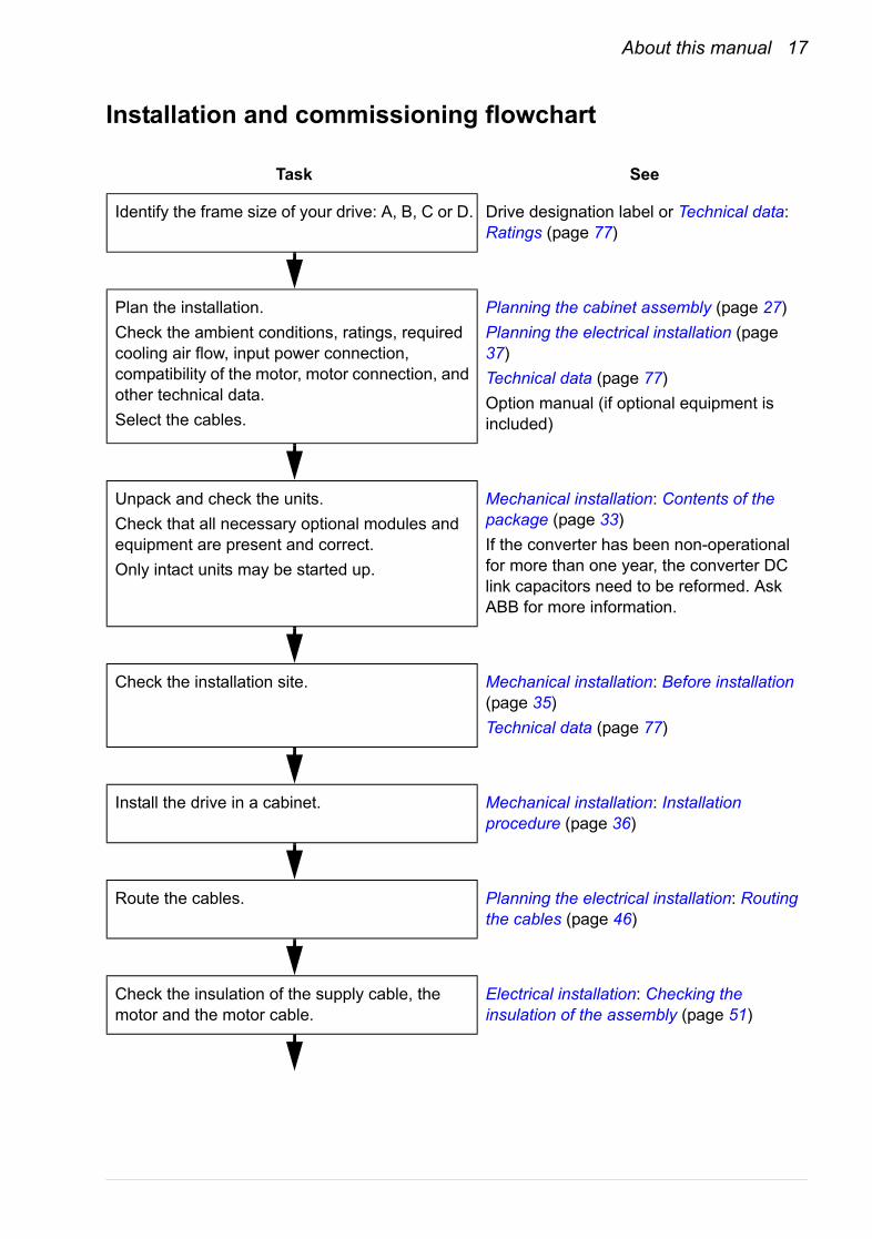
Installation and commissioning flowchart
Task See
Identify the frame size of your drive: A, B, C or D. Drive designation label or Technical data: Ratings (page 77)
Plan the installation.Check the ambient conditions, ratings, required cooling air flow, input power connection, compatibility of the motor, motor connection, and other technical data.Select the cables.
Planning the cabinet assembly (page 27)Planning the electrical installation (page 37)Technical data (page 77)Option manual (if optional equipment is included)
Unpack and check the units.Check that all necessary optional modules and equipment are present and correct.Only intact units may be started up.
Mechanical installation: Contents of the package (page 33)If the converter has been non-operational for more than one year, the converter DC link capacitors need to be reformed. Ask ABB for more information.
Check the installation site. Mechanical installation: Before installation (page 35)Technical data (page 77)
Install the drive in a cabinet. Mechanical installation: Installation procedure (page 36)
Route the cables. Planning the electrical installation: Routing the cables (page 46)
Check the insulation of the supply cable, the motor and the motor cable.
Electrical installation: Checking the insulation of the assembly (page 51)
18 About this manual
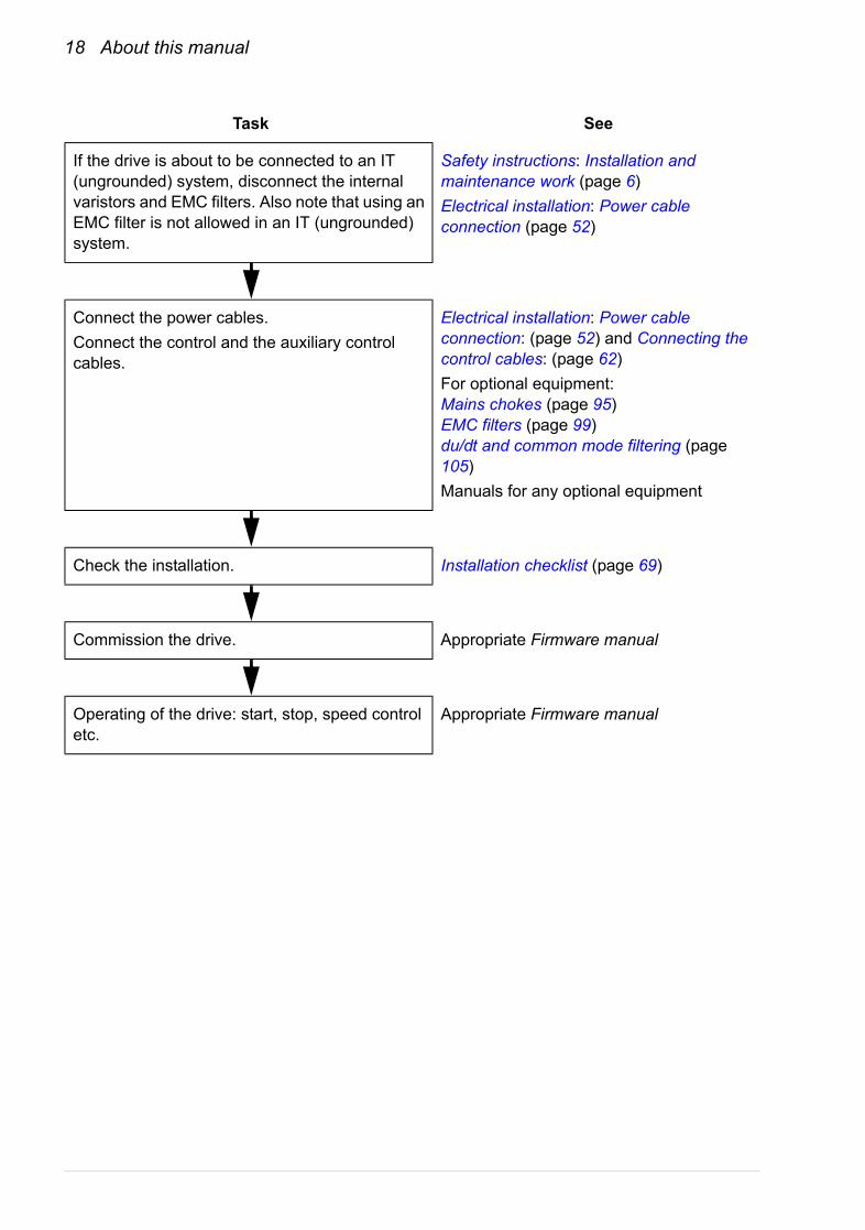
If the drive is about to be connected to an IT (ungrounded) system, disconnect the internal varistors and EMC filters. Also note that using an EMC filter is not allowed in an IT (ungrounded) system.
Safety instructions: Installation and maintenance work (page 6)Electrical installation: Power cable connection (page 52)
Connect the power cables.Connect the control and the auxiliary control cables.
Electrical installation: Power cable connection: (page 52) and Connecting the control cables: (page 62)For optional equipment:Mains chokes (page 95)EMC filters (page 99)du/dt and common mode filtering (page 105)Manuals for any optional equipment
Check the installation. Installation checklist (page 69)
Commission the drive. Appropriate Firmware manual
Operating of the drive: start, stop, speed control etc.
Appropriate Firmware manual
Task See

About this manual 19
Terms and abbreviations
Term/Abbreviation Explanation
CHK-xx Series of optional mains chokes for the ACQ810.
EMC Electromagnetic Compatibility.
FIO-11 Optional analog I/O extension for the ACQ810.
FIO-21 Optional analog/digital I/O extension for the ACQ810.
FIO-31 Optional digital I/O extension for the ACQ810.
FDNA-0x Optional DeviceNet adapter for the ACQ810.
FENA-0x Optional Ethernet/IP adapter for the ACQ810.
FLON-0x Optional LONWORKS® adapter for the ACQ810.
FPBA-0x Optional PROFIBUS DP adapter for the ACQ810.
Frame (size) Size of the drive module. This manual deals with ACQ810-04 frames A, B, C and D. To determine the frame size of a drive module, refer to the drive designation label attached to the drive, or the rating tables in chapter Technical data.
FSCA-0x Optional Modbus adapter for the ACQ810.
IGBT Insulated Gate Bipolar Transistor; a voltage-controlled semiconductor type widely used in inverters due to their easy controllability and high switching frequency.
I/O Input/Output.
JCU The control unit of the drive module. The JCU is installed on top of the power unit. The external I/O control signals are connected to the JCU, or optional I/O extensions mounted on it.
JFI-xx Series of optional EMC filters for the ACQ810.
JMU The memory unit attached to the control unit of the drive.
RFI Radio-frequency interference.

20 About this manual
Operation principle and hardware description 21
Operation principle and hardware description
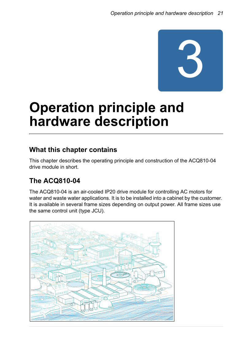
What this chapter containsThis chapter describes the operating principle and construction of the ACQ810-04 drive module in short.
The ACQ810-04The ACQ810-04 is an air-cooled IP20 drive module for controlling AC motors for water and waste water applications. It is to be installed into a cabinet by the customer. It is available in several frame sizes depending on output power. All frame sizes use the same control unit (type JCU).
22 Operation principle and hardware description
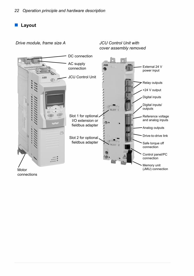
Layout
Slot 1 for optionalI/O extension orfieldbus adapter
AC supply connection
DC connection
Drive module, frame size A JCU Control Unit with cover assembly removed
JCU Control Unit
Slot 2 for optionalfieldbus adapter
Motor connections
External 24 V power input
Relay outputs
+24 V output
Digital inputs
Digital inputs/outputs
Reference voltage and analog inputs
Drive-to-drive link
Safe torque off connection
Control panel/PC connection
Memory unit (JMU) connection
Analog outputs
Operation principle and hardware description 23
Operation principle
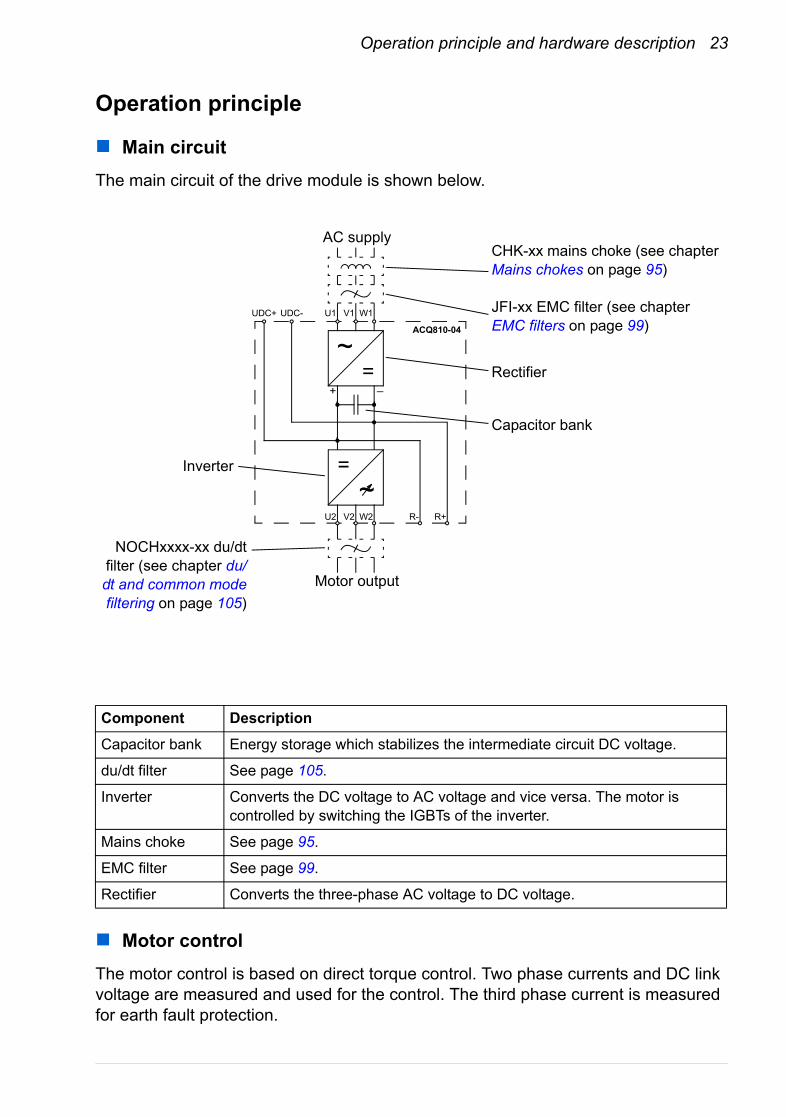
Main circuitThe main circuit of the drive module is shown below.
Motor controlThe motor control is based on direct torque control. Two phase currents and DC link voltage are measured and used for the control. The third phase current is measured for earth fault protection.
Component Description
Capacitor bank Energy storage which stabilizes the intermediate circuit DC voltage.
du/dt filter See page 105.
Inverter Converts the DC voltage to AC voltage and vice versa. The motor is controlled by switching the IGBTs of the inverter.
Mains choke See page 95.
EMC filter See page 99.
Rectifier Converts the three-phase AC voltage to DC voltage.
~=
Motor output
+ –
UDC+ UDC- V1 W1U1
~=
V2 W2U2 R- R+
AC supply
ACQ810-04
Inverter
Capacitor bank
Rectifier
CHK-xx mains choke (see chapter Mains chokes on page 95)
JFI-xx EMC filter (see chapter EMC filters on page 99)
NOCHxxxx-xx du/dtfilter (see chapter du/dt and common modefiltering on page 105)
24 Operation principle and hardware description
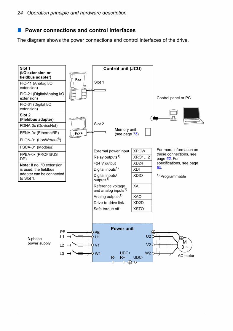
Power connections and control interfacesThe diagram shows the power connections and control interfaces of the drive.
Slot 1
Slot 2
Control unit (JCU)
Fxxx
Fxx
Control panel or PC
Memory unit (see page 75)
Power unit
External power input XPOWRelay outputs1) XRO1…2+24 V output XD24Digital inputs1) XDIDigital inputs/outputs1)
XDIO
Reference voltage and analog inputs1)
XAI
Analog outputs1) XAODrive-to-drive link XD2DSafe torque off XSTO
3-phase power supply
AC motor
U1
V1
W1
L1
L2
L3
PEPEU2
V2
W2
M3 ~
R-UDC+R+ UDC-
For more information on these connections, see page 62. For specifications, see page 85.
1) Programmable
Slot 1(I/O extension or fieldbus adapter)FIO-11 (Analog I/O extension)FIO-21 (Digital/Analog I/O extension)FIO-31 (Digital I/O extension)Slot 2(Fieldbus adapter)FDNA-0x (DeviceNet)
FENA-0x (Ethernet/IP)
FLON-01 (LONWORKS®)
FSCA-01 (Modbus)
FPBA-0x (PROFIBUS DP)Note: If no I/O extension is used, the fieldbus adapter can be connected to Slot 1.
Operation principle and hardware description 25
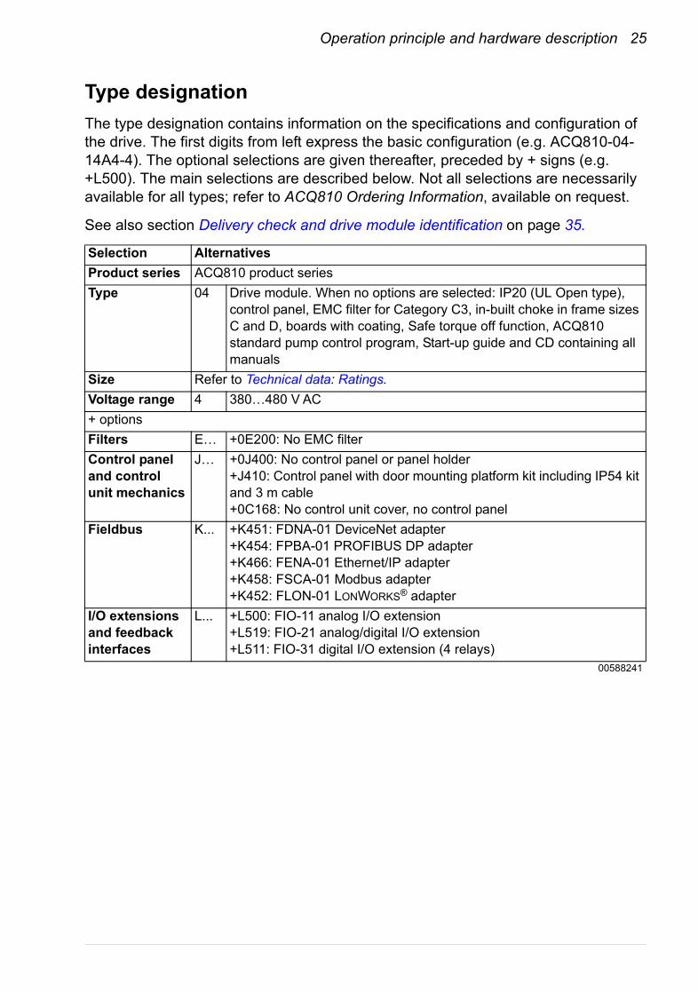
Type designationThe type designation contains information on the specifications and configuration of the drive. The first digits from left express the basic configuration (e.g. ACQ810-04-14A4-4). The optional selections are given thereafter, preceded by + signs (e.g. +L500). The main selections are described below. Not all selections are necessarily available for all types; refer to ACQ810 Ordering Information, available on request.
See also section Delivery check and drive module identification on page 35.
Selection AlternativesProduct series ACQ810 product seriesType 04 Drive module. When no options are selected: IP20 (UL Open type),
control panel, EMC filter for Category C3, in-built choke in frame sizes C and D, boards with coating, Safe torque off function, ACQ810 standard pump control program, Start-up guide and CD containing all manuals
Size Refer to Technical data: Ratings.Voltage range 4 380…480 V AC+ optionsFilters E… +0E200: No EMC filterControl panel and control unit mechanics
J… +0J400: No control panel or panel holder+J410: Control panel with door mounting platform kit including IP54 kit and 3 m cable+0C168: No control unit cover, no control panel
Fieldbus K... +K451: FDNA-01 DeviceNet adapter+K454: FPBA-01 PROFIBUS DP adapter+K466: FENA-01 Ethernet/IP adapter+K458: FSCA-01 Modbus adapter+K452: FLON-01 LONWORKS® adapter
I/O extensions and feedback interfaces
L... +L500: FIO-11 analog I/O extension+L519: FIO-21 analog/digital I/O extension+L511: FIO-31 digital I/O extension (4 relays)
00588241

26 Operation principle and hardware description

Planning the cabinet assembly 27
Planning the cabinet assembly
What this chapter containsThis chapter guides in planning the installation of a drive module into a user-defined cabinet. The issues discussed are essential for safe and trouble-free use of the drive system.
Note: The installation examples in this manual are provided only to help the installer in designing the installation. Please note that the installation must, however, always be designed and made according to applicable local laws and regulations. ABB does not assume any liability whatsoever for any installation which breaches the local laws and/or other regulations.
Cabinet constructionThe cabinet frame must be sturdy enough to carry the weight of the drive components, control circuitry and other equipment installed in it.
The cabinet must protect the drive module against contact and meet the requirements for dust and humidity (see the chapter Technical data).
Disposition of the devicesFor easy installation and maintenance, a spacious layout is recommended. Sufficient cooling air flow, obligatory clearances, cables and cable support structures all require space.
For a layout example, see section Cooling and degrees of protection below.

28 Planning the cabinet assembly
Grounding of mounting structuresMake sure all cross-members or shelves on which drive system components are mounted are properly grounded and the connecting surfaces left unpainted.
Note: Ensure that the components are properly grounded through their fastening points to the installation base.
Note: It is recommended that the EMC filter (if present) and the drive module be mounted on the same mounting plate.
Planning the fastening of the cabinet
WARNING! Do not fasten the cabinet by electric welding. ABB does not assume any liability for damages caused by electric welding as the welding circuit may damage electronic circuits in the cabinet.

Planning the cabinet assembly 29
Main dimensions and free space requirementsThe modules can be installed side by side. The dimensions of the drive modules as well as free space requirements are presented below. For more details, refer to chapter Dimension drawings.
Frame C Frame B Frame AFrame D

30 Planning the cabinet assembly
Note: EMC filters of type JFI-x1 mounted directly above the drive module do not increase the free space requirements. (For EMC filters of type JFI-0x, see the dimension drawing of the filters on page 119.)
The temperature of the cooling air entering the unit must not exceed the maximum allowed ambient temperature (see Ambient conditions in the chapter Technical data). Consider this when installing heat-generating components (such as other drives and mains chokes) nearby.
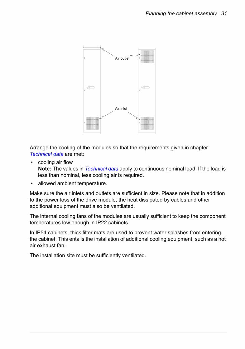
Cooling and degrees of protectionThe cabinet must have enough free space for the components to ensure sufficient cooling. Observe the minimum clearances given for each component.
The air inlets and outlets must be equipped with gratings that• guide the air flow• protect against contact• prevent water splashes from entering the cabinet.
The drawing below shows two typical cabinet cooling solutions. The air inlet is at the bottom of the cabinet, while the outlet is at the top, either on the upper part of the door or on the roof.
300 mm [12”]
200 mm [7.9”]
Planning the cabinet assembly 31
Arrange the cooling of the modules so that the requirements given in chapter Technical data are met:• cooling air flow
Note: The values in Technical data apply to continuous nominal load. If the load is less than nominal, less cooling air is required.
• allowed ambient temperature.
Make sure the air inlets and outlets are sufficient in size. Please note that in addition to the power loss of the drive module, the heat dissipated by cables and other additional equipment must also be ventilated.
The internal cooling fans of the modules are usually sufficient to keep the component temperatures low enough in IP22 cabinets.
In IP54 cabinets, thick filter mats are used to prevent water splashes from entering the cabinet. This entails the installation of additional cooling equipment, such as a hot air exhaust fan.
The installation site must be sufficiently ventilated.
Air inlet
Air outlet
32 Planning the cabinet assembly
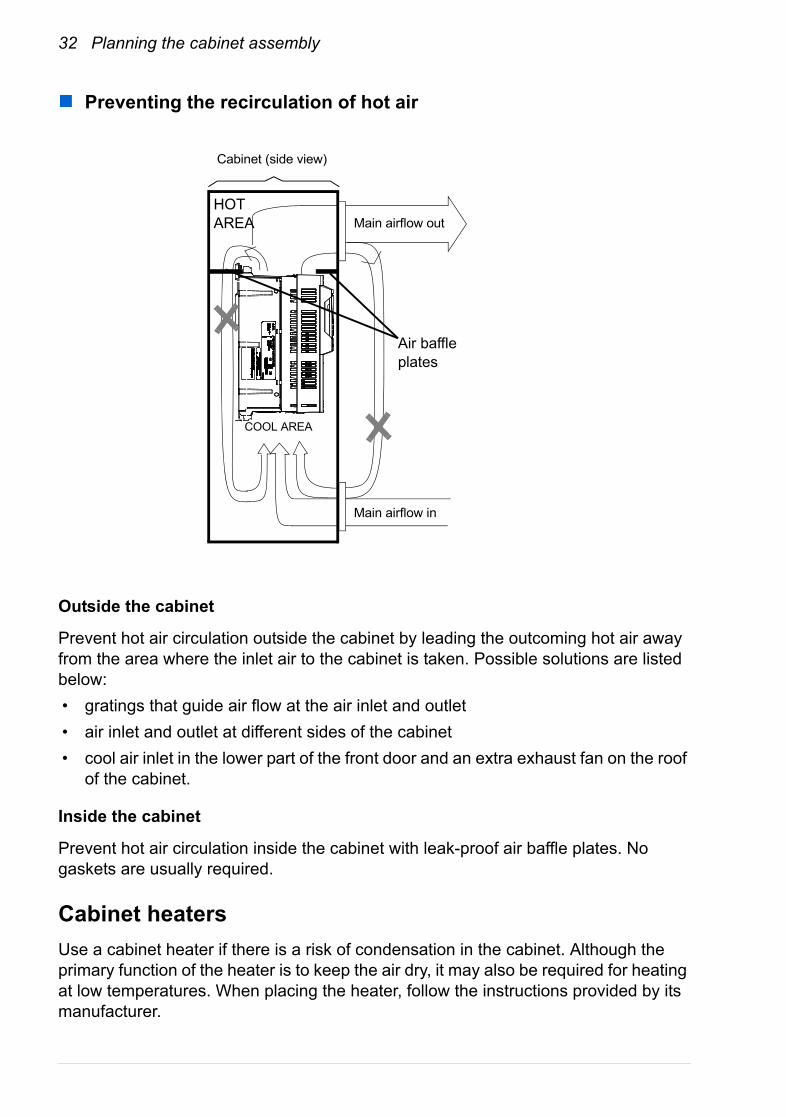
Preventing the recirculation of hot air
Outside the cabinet
Prevent hot air circulation outside the cabinet by leading the outcoming hot air away from the area where the inlet air to the cabinet is taken. Possible solutions are listed below:• gratings that guide air flow at the air inlet and outlet• air inlet and outlet at different sides of the cabinet• cool air inlet in the lower part of the front door and an extra exhaust fan on the roof
of the cabinet.
Inside the cabinet
Prevent hot air circulation inside the cabinet with leak-proof air baffle plates. No gaskets are usually required.
Cabinet heatersUse a cabinet heater if there is a risk of condensation in the cabinet. Although the primary function of the heater is to keep the air dry, it may also be required for heating at low temperatures. When placing the heater, follow the instructions provided by its manufacturer.
HOT AREA Main airflow out
Main airflow in
COOL AREA
Cabinet (side view)
Air baffle plates
Mechanical installation 33
Mechanical installation
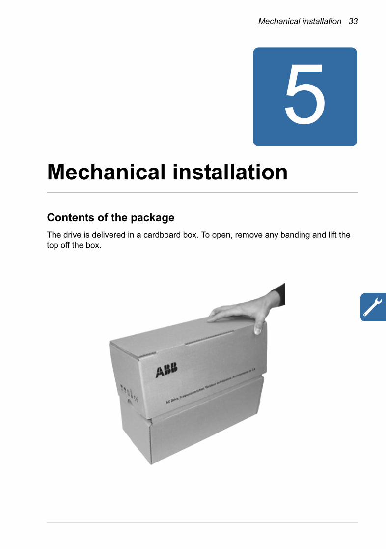
Contents of the packageThe drive is delivered in a cardboard box. To open, remove any banding and lift the top off the box.

34 Mechanical installation
The box contains:• ACQ810-04 drive module, with factory-installed options• three cable clamp plates (two for power cabling, one for control cabling) with
screws• screw-type terminal blocks to be attached to the headers on the JCU Control Unit
and the power unit• category C3 EMC filter (external in frame sizes A and B, internal in frame sizes C
and D)• control panel mounting kit (+J410) if ordered• Start-up guide and manuals CD.
Compartments for cable clamp plates
Compartment for terminal blocks and manuals
ACQ810-04 drive module
EMC filter, controlpanel mounting kit
(Underneath the drivemodule – lift out the
module and openleft-hand side flap to
access)

Mechanical installation 35
Delivery check and drive module identificationCheck that there are no signs of damage. Before attempting installation and operation, check the information on the type designation label of the drive module to verify that the unit is of the correct type. The label is located on the left-hand side of the drive module.
The first digit of the serial number refers to the manufacturing plant. The 2nd and 3rd digit indicate the year of manufacture, while the 4th and 5th digits indicate the week. Digits 6 to 10 are a running integer starting every week at 00001.
Before installationSee Technical data for the allowed operation conditions of the drive. Refer to Dimension drawings for frame details.
The wall the drive is to be mounted on must be as even as possible, of non-flammable material and strong enough to carry the weight of the drive. The floor/material below the drive must be non-flammable.
Type code + options(see page 25)
Serial numberRatings
Compliance markings
Frame size
36 Mechanical installation
Installation procedure
Direct wall mounting1. Mark the locations for the four holes. The mounting points are shown in
Dimension drawings.2. Fix the screws or bolts to the marked locations.3. Position the drive onto the screws on the wall. Note: Only lift the drive by its
chassis.4. Tighten the screws.
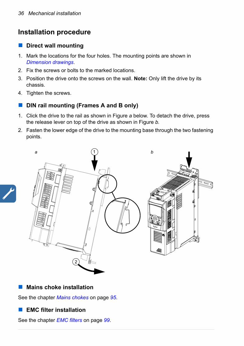
DIN rail mounting (Frames A and B only)
1. Click the drive to the rail as shown in Figure a below. To detach the drive, press the release lever on top of the drive as shown in Figure b.
2. Fasten the lower edge of the drive to the mounting base through the two fastening points.
Mains choke installationSee the chapter Mains chokes on page 95.
EMC filter installationSee the chapter EMC filters on page 99.
a b1
2

Planning the electrical installation 37
Planning the electrical installation
What this chapter containsThis chapter contains the instructions that you must follow when selecting the motor, cables, protections, cable routing and way of operation for the drive. If the recommendations given by ABB are not followed, the drive may experience problems that the warranty does not cover.
Note: The installation must always be designed and made according to applicable local laws and regulations. ABB does not assume any liability whatsoever for any installation which breaches the local laws and/or other regulations.
Motor selectionSelect the (3-phase AC induction) motor according to the rating table in the chapter Technical data. The table lists the typical motor power for each drive type. See also requirements table on page 106.
Supply connectionUse a fixed connection to the AC power line.
WARNING! As the leakage current of the device typically exceeds 3.5 mA, a fixed installation is required according to IEC 61800-5-1.
38 Planning the electrical installation
Supply disconnecting deviceInstall a hand-operated input disconnecting device (disconnecting means) between the AC power source and the drive. The disconnecting device must be of a type that can be locked to the open position for installation and maintenance work.
EuropeIf the drive is used in an application which must meet the European Union Machinery Directive according to standard EN 60204-1 Safety of Machinery, the disconnecting device must be one of the following types:• a switch-disconnector of utilization category AC-23B (EN 60947-3)• a disconnector that has an auxiliary contact that in all cases causes switching
devices to break the load circuit before the opening of the main contacts of the disconnector (EN 60947-3)
• a circuit breaker suitable for isolation in accordance with EN 60947-2.
Other regionsThe disconnecting means must conform to the applicable safety regulations.
Thermal overload and short circuit protection
Thermal overload protection
The drive protects itself and the input and motor cables against thermal overload when the cables are dimensioned according to the nominal current of the drive. No additional thermal protection devices are needed.
WARNING! If the drive is connected to multiple motors, a separate thermal overload switch or a circuit breaker must be used for protecting each cable and motor. These devices may require a separate fuse to cut off the short-
circuit current.
Protection against short-circuit in motor cableThe drive protects the motor cable and the motor in a short-circuit situation when the motor cable is dimensioned according to the nominal current of the drive. No additional protection devices are needed.
Protection against short-circuit in the supply cable or the driveProtect the supply cable with fuses or circuit breakers. Fuse recommendations are given in the chapter Technical data. When placed at the distribution board, standard IEC gG fuses or UL type T fuses will protect the input cable in short-circuit situations,
Planning the electrical installation 39
restrict drive damage and prevent damage to adjoining equipment in case of a short circuit inside the drive.
Operating time of the fuses and circuit breakers
Check that the operating time of the fuse is below 0.5 seconds. The operating time depends on the type, the supply network impedance, and the cross-sectional area, material and length of the supply cable. US fuses must be of the “non-time delay” type.
Circuit breakers
The protective characteristics of circuit breakers depend on the supply voltage as well as the type and construction of the breakers. There are also limitations pertaining to the short-circuit capacity of the supply network. Your local ABB representative can help you in selecting the breaker type when the supply network characteristics are known.
Motor thermal protection
According to regulations, the motor must be protected against thermal overload and the current must be switched off when overloading is detected. The drive includes a motor thermal protection function that protects the motor and switches off the current when necessary. Depending on a drive parameter value, the function either monitors a calculated temperature value (based on a motor thermal model) or an actual temperature indication given by motor temperature sensors. The user can tune the thermal model further by feeding in additional motor and load data.
PTC sensors can be connected directly to the ACQ810-04. See page 65 in this manual, and the appropriate Firmware manual for the parameter settings concerning motor thermal protection.
Ground fault protectionThe drive is equipped with an internal ground fault protective function to protect the unit against ground faults in the motor and the motor cable. This is not a personal safety or a fire protection feature. The ground fault protective function can be disabled with a parameter, refer to the appropriate Firmware manual.
The optional EMC filter includes capacitors connected between the main circuit and the frame. These capacitors and long motor cables increase the ground leakage current and may cause fault current circuit breakers to function.
Emergency stop devicesFor safety reasons, install the emergency stop devices at each operator control station and at other operating stations where emergency stop may be needed.

40 Planning the electrical installation
Note: Pressing the stop key on the control panel of the drive does not generate an emergency stop of the motor or separate the drive from dangerous potential.
Safe torque offThe drive supports the Safe torque off function according to standards EN 61800-5-2:2007; EN 954-1:1997; IEC/EN 60204-1:1997; EN 61508:2002 and EN 1037:1996.
The Safe torque off function disables the control voltage of the power semiconductors of the drive output stage, thus preventing the inverter from generating the voltage required to rotate the motor (see diagram below). By using this function, short-time operations (like cleaning) and/or maintenance work on non-electrical parts of the machinery can be performed without switching off the power supply to the drive.
WARNING! The Safe torque off function does not disconnect the voltage of the main and auxiliary circuits from the drive. Therefore maintenance work on electrical parts of the drive or the motor can only be carried out after isolating
the drive system from the main supply.
Control circuit
+24 VXSTO:1
XSTO:2
XSTO:3
XSTO:4
U2/V2/W2
UDC+
UDC-
Drive
Output stage (1 phase shown)
Safe torque off connection on JCU
Activation switch
Notes:• The contacts of the activation switch must open/close within 200 ms of each other.• The maximum cable length between the drive and the activation switch is 25 m (82 ft)
Planning the electrical installation 41
Note: If a running drive is stopped by using the Safe torque off function, the drive will cut off the motor supply voltage and the motor will coast to stop.
Selecting the power cables
General rulesDimension the supply (input power) and motor cables according to local regulations.• The cable must be able to carry the drive load current. See the chapter Technical
data for the rated currents.• The cable must be rated for at least 70 °C (US: 75 °C [167 °F]) maximum
permissible temperature of conductor in continuous use.• The inductance and impedance of the PE conductor/cable (grounding wire) must
be rated according to permissible touch voltage appearing under fault conditions (so that the fault point voltage will not rise excessively when a ground fault occurs).
• 600 V AC cable is accepted for up to 500 V AC.• Refer to the chapter Technical data for EMC requirements.
Symmetrical shielded motor cable must be used (see the figure below) to meet the EMC requirements of the CE and C-tick marks.
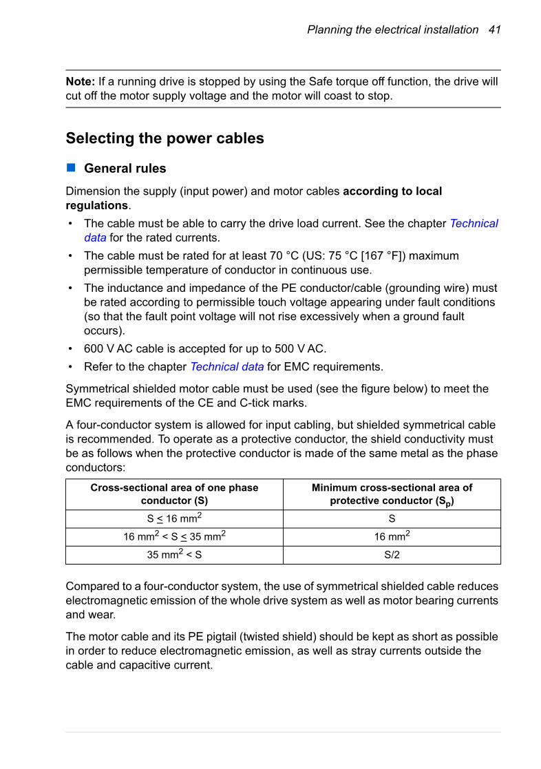
A four-conductor system is allowed for input cabling, but shielded symmetrical cable is recommended. To operate as a protective conductor, the shield conductivity must be as follows when the protective conductor is made of the same metal as the phase conductors:
Compared to a four-conductor system, the use of symmetrical shielded cable reduces electromagnetic emission of the whole drive system as well as motor bearing currents and wear.
The motor cable and its PE pigtail (twisted shield) should be kept as short as possible in order to reduce electromagnetic emission, as well as stray currents outside the cable and capacitive current.
Cross-sectional area of one phase conductor (S)
Minimum cross-sectional area of protective conductor (Sp)
S < 16 mm2 S
16 mm2 < S < 35 mm2 16 mm2
35 mm2 < S S/2
42 Planning the electrical installation
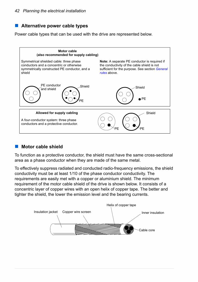
Alternative power cable typesPower cable types that can be used with the drive are represented below.
Motor cable shieldTo function as a protective conductor, the shield must have the same cross-sectional area as a phase conductor when they are made of the same metal.
To effectively suppress radiated and conducted radio-frequency emissions, the shield conductivity must be at least 1/10 of the phase conductor conductivity. The requirements are easily met with a copper or aluminium shield. The minimum requirement of the motor cable shield of the drive is shown below. It consists of a concentric layer of copper wires with an open helix of copper tape. The better and tighter the shield, the lower the emission level and the bearing currents.
Symmetrical shielded cable: three phase conductors and a concentric or otherwise symmetrically constructed PE conductor, and a shield
Motor cable(also recommended for supply cabling)
PE conductor and shield
Shield Shield
Note: A separate PE conductor is required if the conductivity of the cable shield is not sufficient for the purpose. See section General rules above.
A four-conductor system: three phase conductors and a protective conductor.
Shield
PE PE
Allowed for supply cabling
PE PE
Insulation jacket Copper wire screen
Helix of copper tape
Cable core
Inner insulation
Planning the electrical installation 43
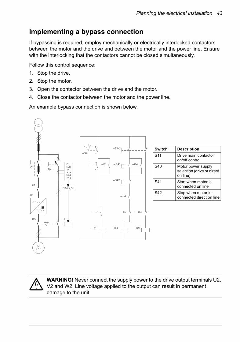
Implementing a bypass connectionIf bypassing is required, employ mechanically or electrically interlocked contactors between the motor and the drive and between the motor and the power line. Ensure with the interlocking that the contactors cannot be closed simultaneously.
Follow this control sequence:1. Stop the drive.2. Stop the motor.3. Open the contactor between the drive and the motor.4. Close the contactor between the motor and the power line.
An example bypass connection is shown below.
WARNING! Never connect the supply power to the drive output terminals U2, V2 and W2. Line voltage applied to the output can result in permanent damage to the unit.
Switch DescriptionS11 Drive main contactor
on/off controlS40 Motor power supply
selection (drive or direct on line)
S41 Start when motor is connected on line
S42 Stop when motor is connected direct on line
44 Planning the electrical installation
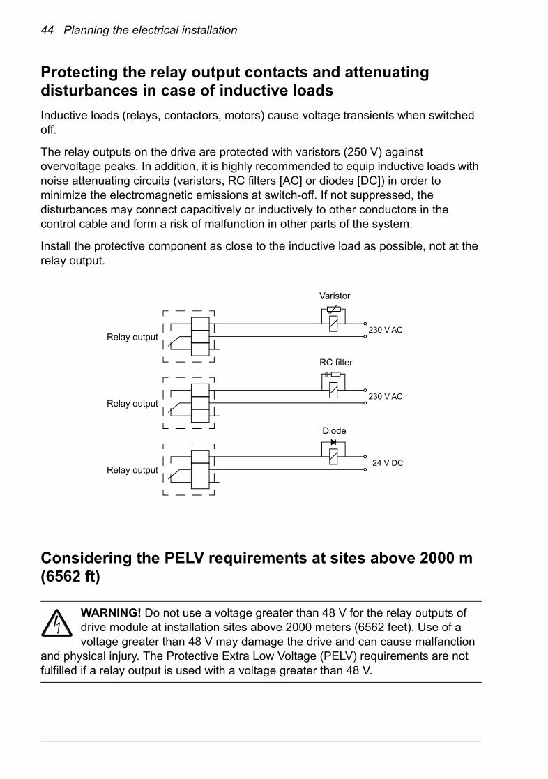
Protecting the relay output contacts and attenuating disturbances in case of inductive loadsInductive loads (relays, contactors, motors) cause voltage transients when switched off.
The relay outputs on the drive are protected with varistors (250 V) against overvoltage peaks. In addition, it is highly recommended to equip inductive loads with noise attenuating circuits (varistors, RC filters [AC] or diodes [DC]) in order to minimize the electromagnetic emissions at switch-off. If not suppressed, the disturbances may connect capacitively or inductively to other conductors in the control cable and form a risk of malfunction in other parts of the system.
Install the protective component as close to the inductive load as possible, not at the relay output.
Considering the PELV requirements at sites above 2000 m (6562 ft)
WARNING! Do not use a voltage greater than 48 V for the relay outputs of drive module at installation sites above 2000 meters (6562 feet). Use of a voltage greater than 48 V may damage the drive and can cause malfanction
and physical injury. The Protective Extra Low Voltage (PELV) requirements are not fulfilled if a relay output is used with a voltage greater than 48 V.
24 V DC
230 V AC
230 V ACRelay output
Varistor
RC filter
Diode
Relay output
Relay output
Planning the electrical installation 45
Selecting the control cablesIt is recommended that all control cables be shielded.
Double-shielded twisted pair cable is recommended for analog signals. For pulse encoder cabling, follow the instructions given by the encoder manufacturer. Use one individually-shielded pair for each signal. Do not use a common return for different analog signals.
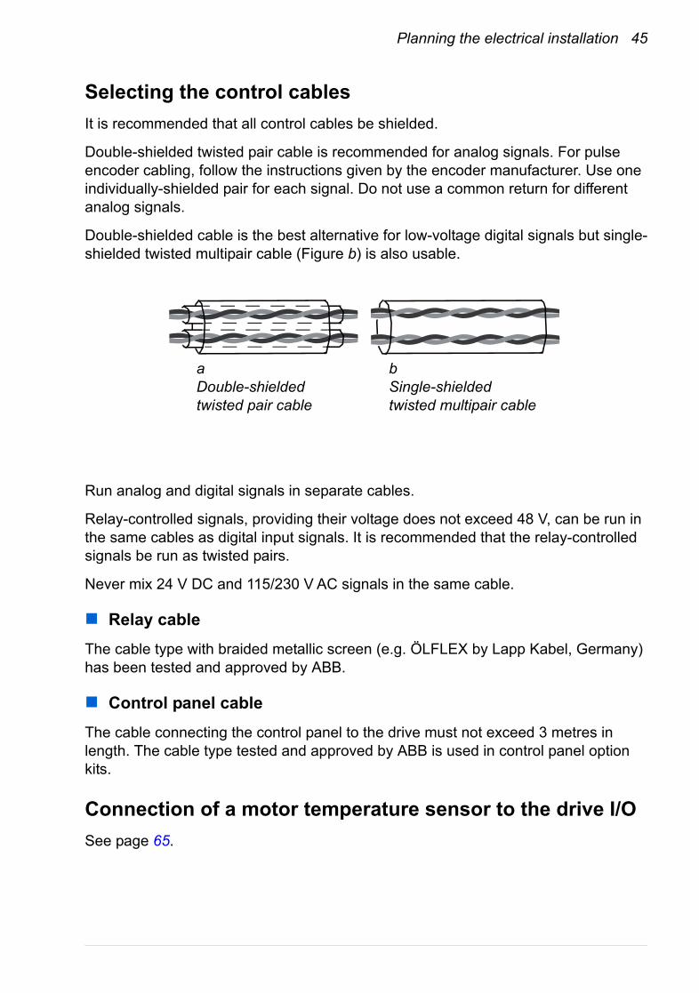
Double-shielded cable is the best alternative for low-voltage digital signals but single-shielded twisted multipair cable (Figure b) is also usable.
Run analog and digital signals in separate cables.
Relay-controlled signals, providing their voltage does not exceed 48 V, can be run in the same cables as digital input signals. It is recommended that the relay-controlled signals be run as twisted pairs.
Never mix 24 V DC and 115/230 V AC signals in the same cable.
Relay cableThe cable type with braided metallic screen (e.g. ÖLFLEX by Lapp Kabel, Germany) has been tested and approved by ABB.
Control panel cableThe cable connecting the control panel to the drive must not exceed 3 metres in length. The cable type tested and approved by ABB is used in control panel option kits.
Connection of a motor temperature sensor to the drive I/OSee page 65.
aDouble-shielded twisted pair cable
bSingle-shielded twisted multipair cable
46 Planning the electrical installation
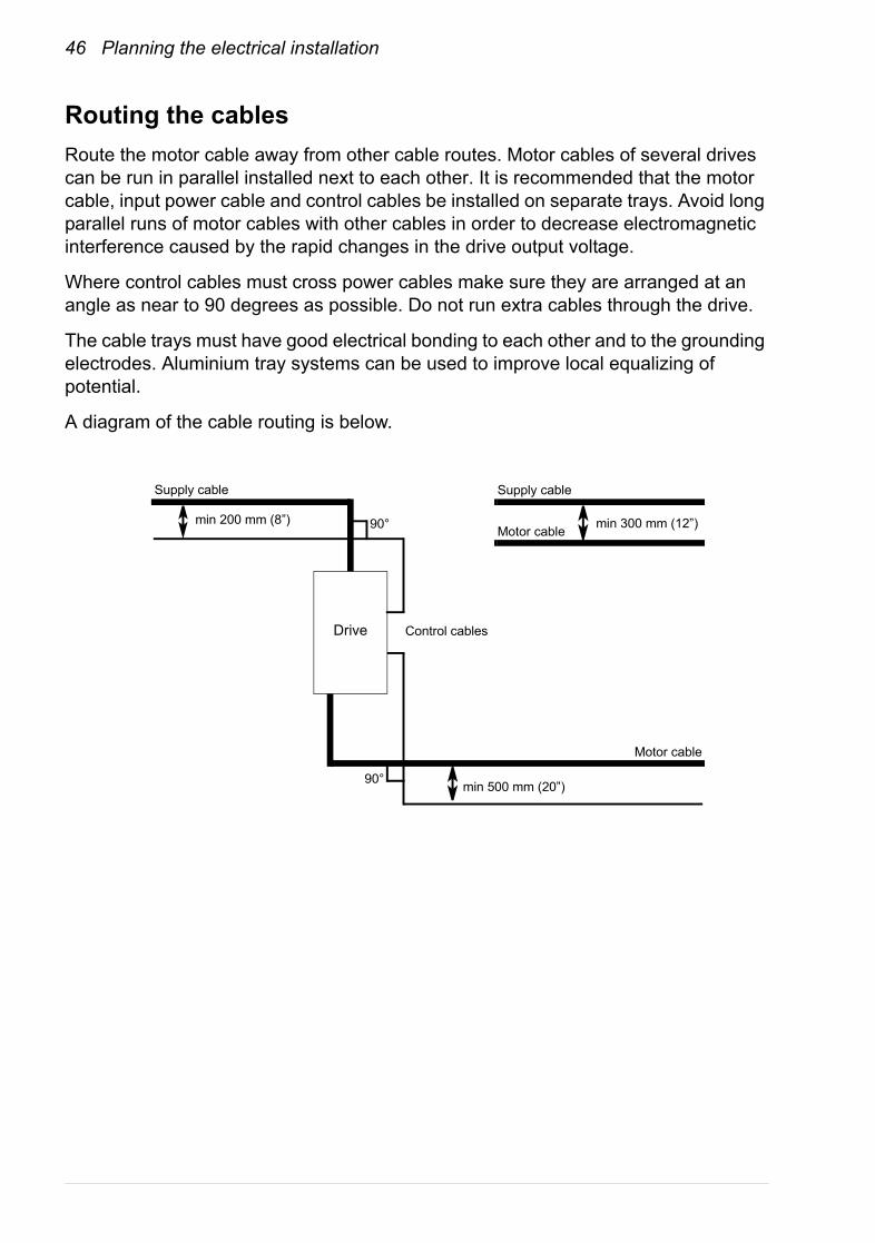
Routing the cablesRoute the motor cable away from other cable routes. Motor cables of several drives can be run in parallel installed next to each other. It is recommended that the motor cable, input power cable and control cables be installed on separate trays. Avoid long parallel runs of motor cables with other cables in order to decrease electromagnetic interference caused by the rapid changes in the drive output voltage.
Where control cables must cross power cables make sure they are arranged at an angle as near to 90 degrees as possible. Do not run extra cables through the drive.
The cable trays must have good electrical bonding to each other and to the grounding electrodes. Aluminium tray systems can be used to improve local equalizing of potential.
A diagram of the cable routing is below.
min 500 mm (20”)
Control cables
min 200 mm (8”) min 300 mm (12”)
Supply cable
Motor cable
Drive
Motor cable
90°
Supply cable
90°
Planning the electrical installation 47
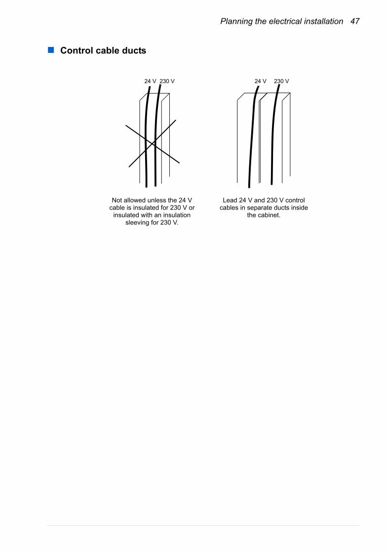
Control cable ducts
230 V24 V24 V 230 V
Lead 24 V and 230 V control cables in separate ducts inside
the cabinet.
Not allowed unless the 24 V cable is insulated for 230 V or
insulated with an insulation sleeving for 230 V.

48 Planning the electrical installation

Electrical installation 49
Electrical installation
What this chapter containsThis chapter describes the electrical installation procedure of the drive.
WARNING! The work described in this chapter may only be carried out by a qualified electrician. Follow the Safety instructions on the first pages of this manual. Ignoring the safety instructions can cause injury or death.
Make sure that the drive is disconnected from the supply (input power) during installation. If the drive is already connected to the supply, wait for 5 minutes after disconnecting the input power.
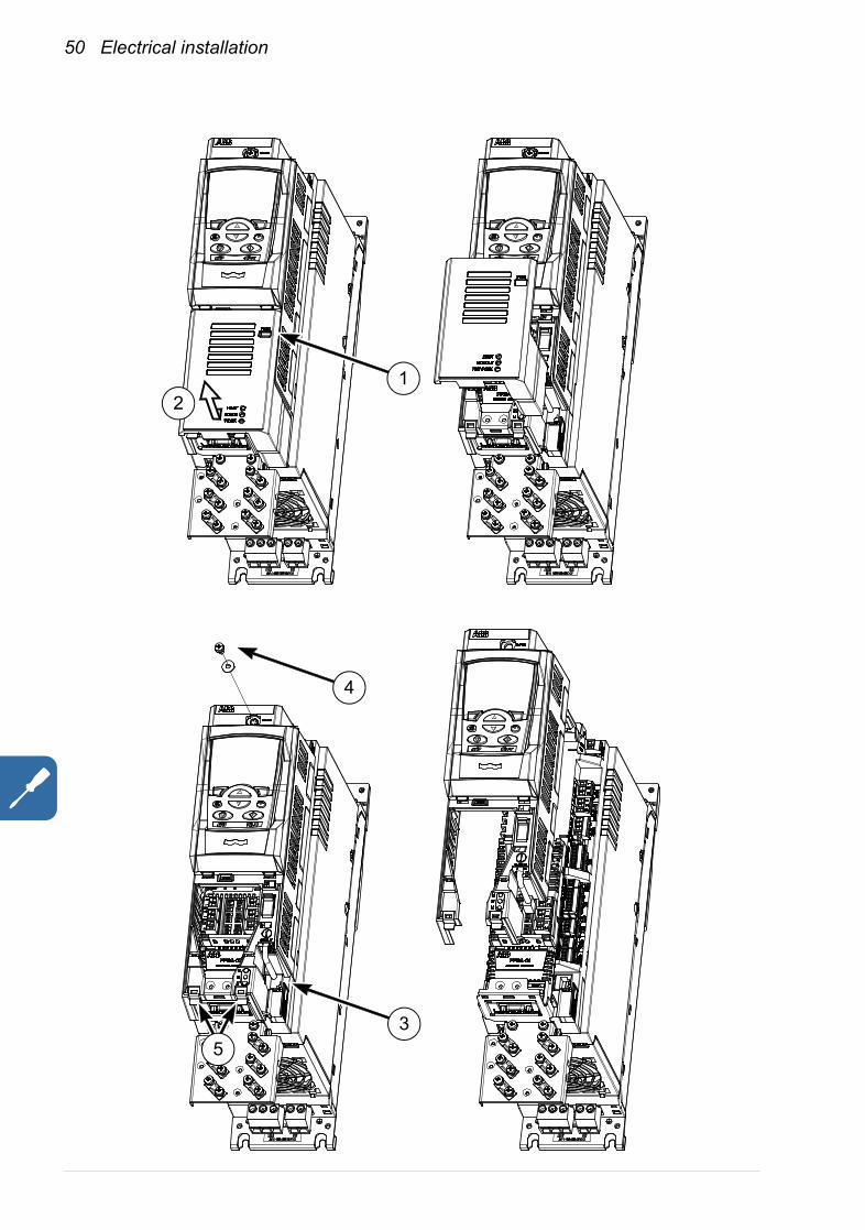
Removing the cover assemblyThe cover assembly needs to be removed before the installation of optional modules and the connection of control cabling. Follow this procedure to remove the cover assembly. The numbers refer to the illustrations below.• Press the tab (1) slightly with a screwdriver.• Slide the lower cover plate slightly downwards and pull it out (2).• Disconnect the panel cable (3) if present.• Remove the screw (4) at the top of the cover assembly.• Carefully pull the lower part of the base outwards by the two tabs (5).
Refit the cover in reverse order to the above procedure.
50 Electrical installation
12
3
4
5

Electrical installation 51
Checking the insulation of the assembly
DriveDo not make any voltage tolerance or insulation resistance tests (e.g. hi-pot or megger) on any part of the drive as testing can damage the drive. Every drive has been tested for insulation between the main circuit and the chassis at the factory. Also, there are voltage-limiting circuits inside the drive which cut down the testing voltage automatically.
Supply cable
Check the insulation of the supply (input) cable according to local regulations before connecting to the drive.
Motor and motor cable
Check the insulation of the motor and motor cable as follows:1. Check that the motor cable is connected to the motor, and disconnected from the
drive output terminals U2, V2 and W2.2. Measure the insulation resistance between each phase conductor and the
Protective Earth conductor using a measuring voltage of 500 V DC. The insulation resistance of an ABB motor must exceed 100 Mohm (reference value at 25 °C or 77 °F). For the insulation resistance of other motors, please consult the manufacturer’s instructions. Note: Moisture inside the motor casing will reduce the insulation resistance. If moisture is suspected, dry the motor and repeat the measurement.
ohm
M3~
U1
V1
W1 PE
52 Electrical installation
Power cable connection
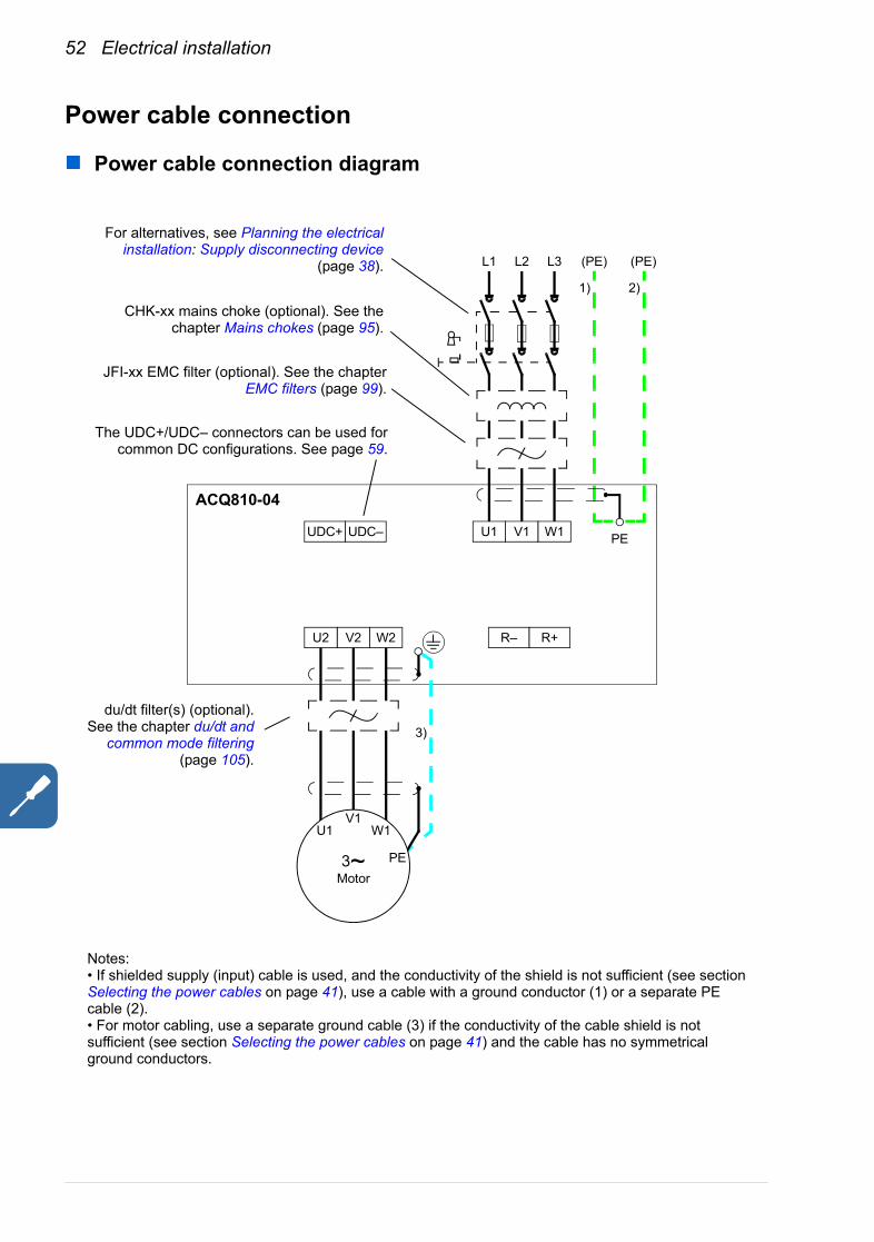
Power cable connection diagram
1)
(PE) (PE)
3)
PE
For alternatives, see Planning the electricalinstallation: Supply disconnecting device
(page 38). L1 L2 L3
UDC+ UDC–
R– R+
2)
U2 V2 W2
U1 V1 W1
3~Motor
V1W1U1
ACQ810-04
CHK-xx mains choke (optional). See thechapter Mains chokes (page 95).
JFI-xx EMC filter (optional). See the chapterEMC filters (page 99).
Notes:• If shielded supply (input) cable is used, and the conductivity of the shield is not sufficient (see section Selecting the power cables on page 41), use a cable with a ground conductor (1) or a separate PE cable (2).• For motor cabling, use a separate ground cable (3) if the conductivity of the cable shield is not sufficient (see section Selecting the power cables on page 41) and the cable has no symmetrical ground conductors.
PE
The UDC+/UDC– connectors can be used forcommon DC configurations. See page 59.
du/dt filter(s) (optional).See the chapter du/dt and
common mode filtering(page 105).
Electrical installation 53
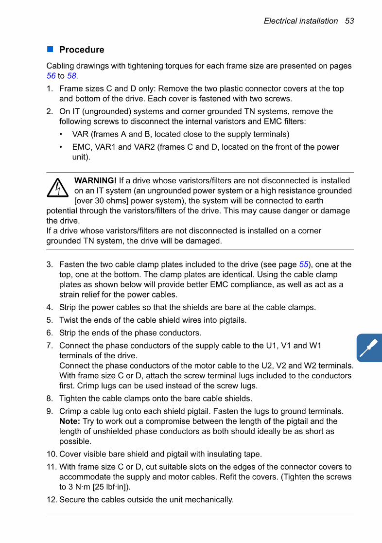
ProcedureCabling drawings with tightening torques for each frame size are presented on pages 56 to 58.1. Frame sizes C and D only: Remove the two plastic connector covers at the top
and bottom of the drive. Each cover is fastened with two screws.2. On IT (ungrounded) systems and corner grounded TN systems, remove the
following screws to disconnect the internal varistors and EMC filters:• VAR (frames A and B, located close to the supply terminals)• EMC, VAR1 and VAR2 (frames C and D, located on the front of the power
unit).
WARNING! If a drive whose varistors/filters are not disconnected is installed on an IT system (an ungrounded power system or a high resistance grounded [over 30 ohms] power system), the system will be connected to earth
potential through the varistors/filters of the drive. This may cause danger or damage the drive.If a drive whose varistors/filters are not disconnected is installed on a corner grounded TN system, the drive will be damaged.
3. Fasten the two cable clamp plates included to the drive (see page 55), one at the top, one at the bottom. The clamp plates are identical. Using the cable clamp plates as shown below will provide better EMC compliance, as well as act as a strain relief for the power cables.
4. Strip the power cables so that the shields are bare at the cable clamps.5. Twist the ends of the cable shield wires into pigtails.6. Strip the ends of the phase conductors.7. Connect the phase conductors of the supply cable to the U1, V1 and W1
terminals of the drive.Connect the phase conductors of the motor cable to the U2, V2 and W2 terminals.With frame size C or D, attach the screw terminal lugs included to the conductors first. Crimp lugs can be used instead of the screw lugs.
8. Tighten the cable clamps onto the bare cable shields.9. Crimp a cable lug onto each shield pigtail. Fasten the lugs to ground terminals.
Note: Try to work out a compromise between the length of the pigtail and the length of unshielded phase conductors as both should ideally be as short as possible.
10. Cover visible bare shield and pigtail with insulating tape.11. With frame size C or D, cut suitable slots on the edges of the connector covers to
accommodate the supply and motor cables. Refit the covers. (Tighten the screws to 3 N·m [25 lbf·in]).
12. Secure the cables outside the unit mechanically.
54 Electrical installation
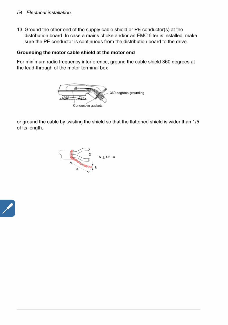
13. Ground the other end of the supply cable shield or PE conductor(s) at the distribution board. In case a mains choke and/or an EMC filter is installed, make sure the PE conductor is continuous from the distribution board to the drive.
Grounding the motor cable shield at the motor end
For minimum radio frequency interference, ground the cable shield 360 degrees at the lead-through of the motor terminal box
or ground the cable by twisting the shield so that the flattened shield is wider than 1/5 of its length.
360 degrees grounding
Conductive gaskets
a b
b > 1/5 · a
Electrical installation 55
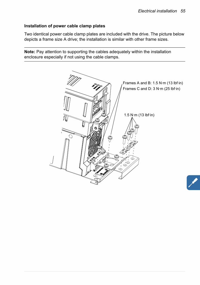
Installation of power cable clamp plates
Two identical power cable clamp plates are included with the drive. The picture below depicts a frame size A drive; the installation is similar with other frame sizes.
Note: Pay attention to supporting the cables adequately within the installation enclosure especially if not using the cable clamps.
Frames A and B: 1.5 N·m (13 lbf·in)Frames C and D: 3 N·m (25 lbf·in)
1.5 N·m (13 lbf·in)
56 Electrical installation
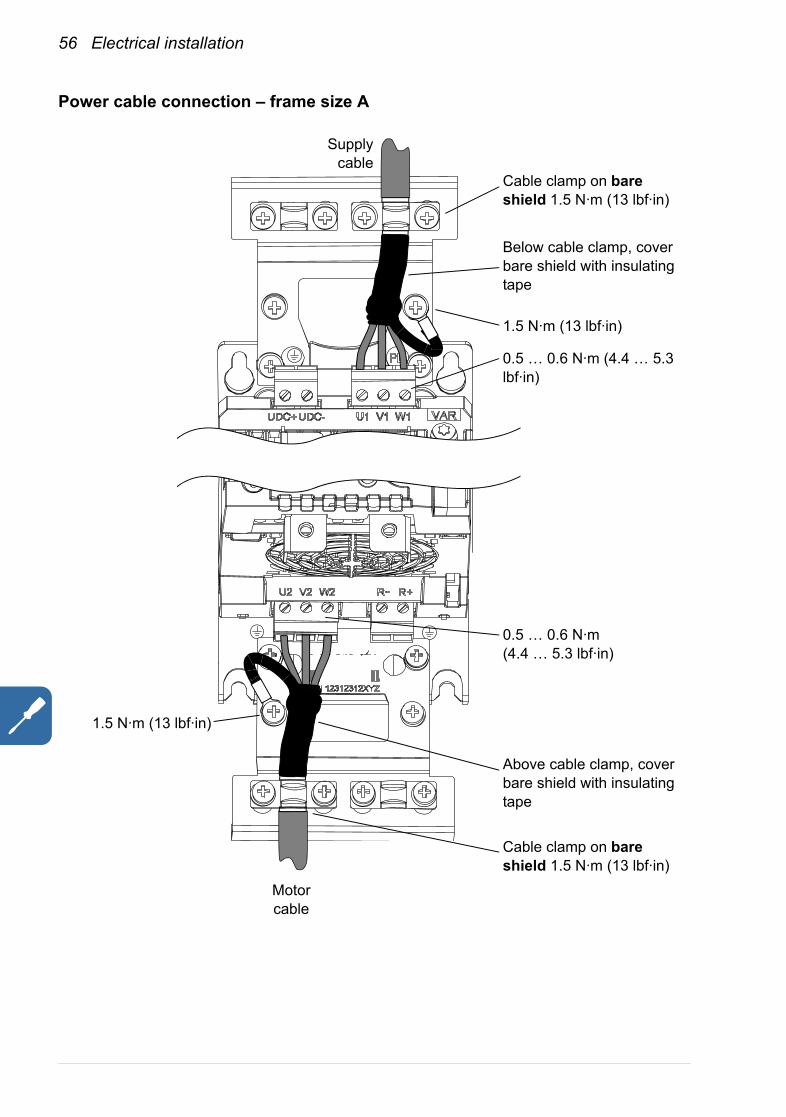
Power cable connection – frame size A
Supplycable
Below cable clamp, cover bare shield with insulating tape
Cable clamp on bare shield 1.5 N·m (13 lbf·in)
Above cable clamp, cover bare shield with insulating tape
1.5 N·m (13 lbf·in)
Cable clamp on bare shield 1.5 N·m (13 lbf·in)
0.5 … 0.6 N·m (4.4 … 5.3 lbf·in)
0.5 … 0.6 N·m (4.4 … 5.3 lbf·in)
Motor cable
1.5 N·m (13 lbf·in)

Electrical installation 57
Power cable connection – frame size B
Supplycable
Below cable clamp, cover bare shield with insulating tape
Cable clamp on bare shield 1.5 N·m (13 lbf·in)
Above cable clamp, cover bare shield with insulating tape
Cable clamp on bare shield 1.5 N·m (13 lbf·in)
1.5 N·m (13 lbf·in)
1.2 … 1.5 N·m(10.6 … 13.3 lbf·in)
Motor cable
U1 V1 W1
U2 V2 W2 R+R-
1.5 N·m (13 lbf·in)
58 Electrical installation
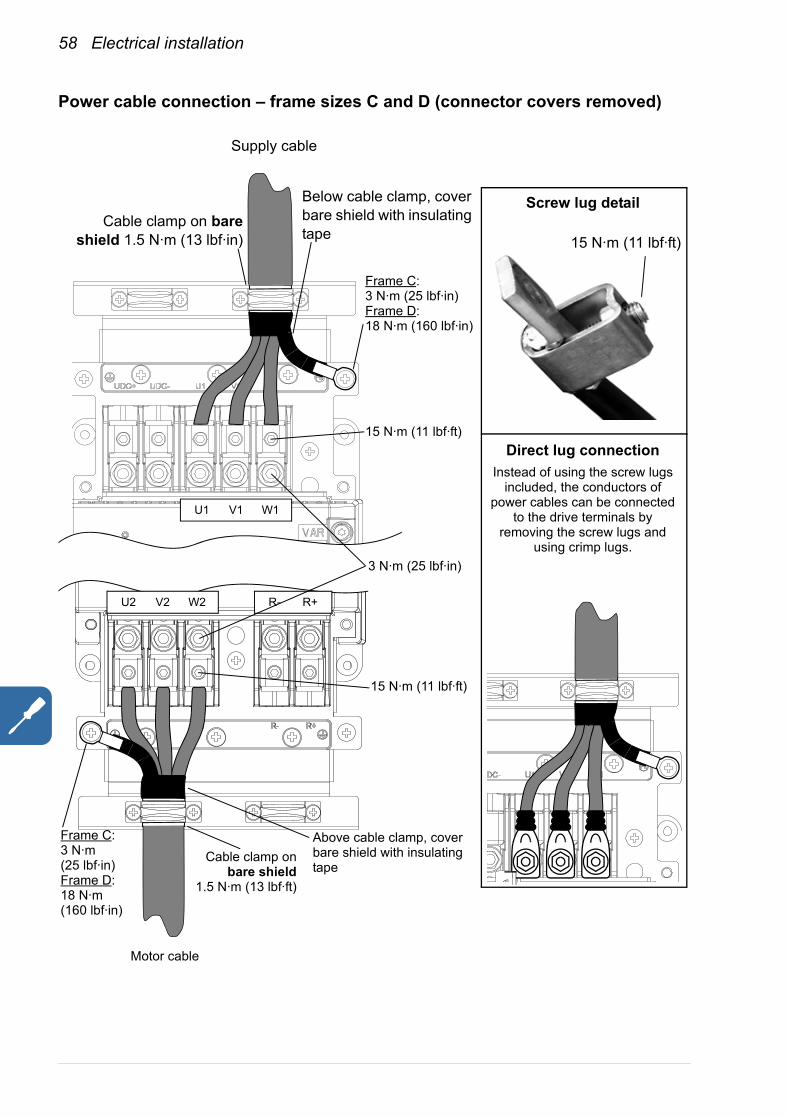
Power cable connection – frame sizes C and D (connector covers removed)
Supply cable
U2 V2 W2
Above cable clamp, cover bare shield with insulating tape
Screw lug detail
Direct lug connectionInstead of using the screw lugs
included, the conductors of power cables can be connected
to the drive terminals by removing the screw lugs and
using crimp lugs.
U1 V1 W1
Below cable clamp, cover bare shield with insulating tape
Cable clamp on bareshield 1.5 N·m (13 lbf·in)
R- R+
Cable clamp onbare shield
1.5 N·m (13 lbf·ft)
15 N·m (11 lbf·ft)
Motor cable
Frame C:3 N·m (25 lbf·in)Frame D:18 N·m (160 lbf·in)
3 N·m (25 lbf·in)
15 N·m (11 lbf·ft)
15 N·m (11 lbf·ft)
Frame C:3 N·m (25 lbf·in)Frame D:18 N·m(160 lbf·in)
Electrical installation 59
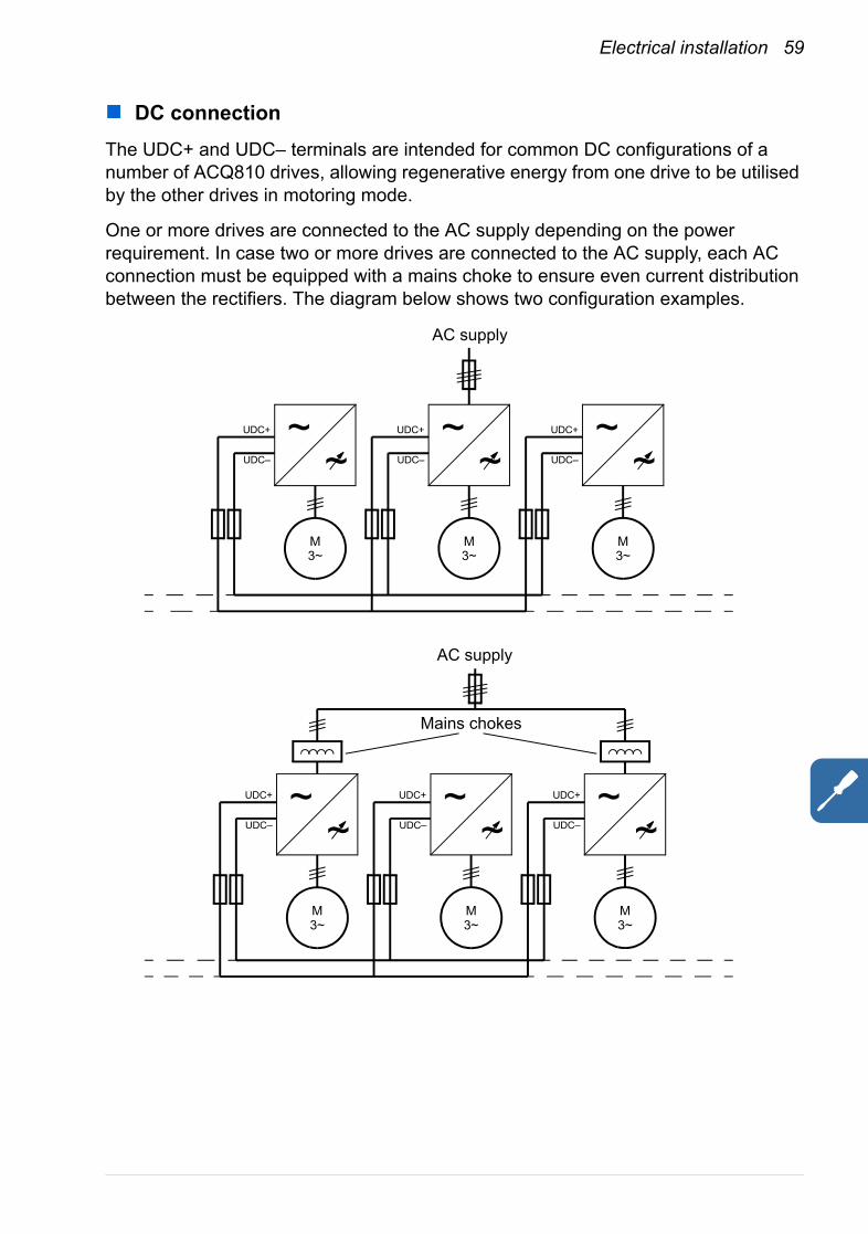
DC connectionThe UDC+ and UDC– terminals are intended for common DC configurations of a number of ACQ810 drives, allowing regenerative energy from one drive to be utilised by the other drives in motoring mode.
One or more drives are connected to the AC supply depending on the power requirement. In case two or more drives are connected to the AC supply, each AC connection must be equipped with a mains choke to ensure even current distribution between the rectifiers. The diagram below shows two configuration examples.
AC supply
M3~
~~
M3~
M3~
AC supply
Mains chokes
~~
~~
UDC+
UDC–
UDC+
UDC–
M3~
~~
UDC+
UDC–
UDC+
UDC–
M3~
~~
UDC+
UDC–
M3~
~~
UDC+
UDC–
60 Electrical installation
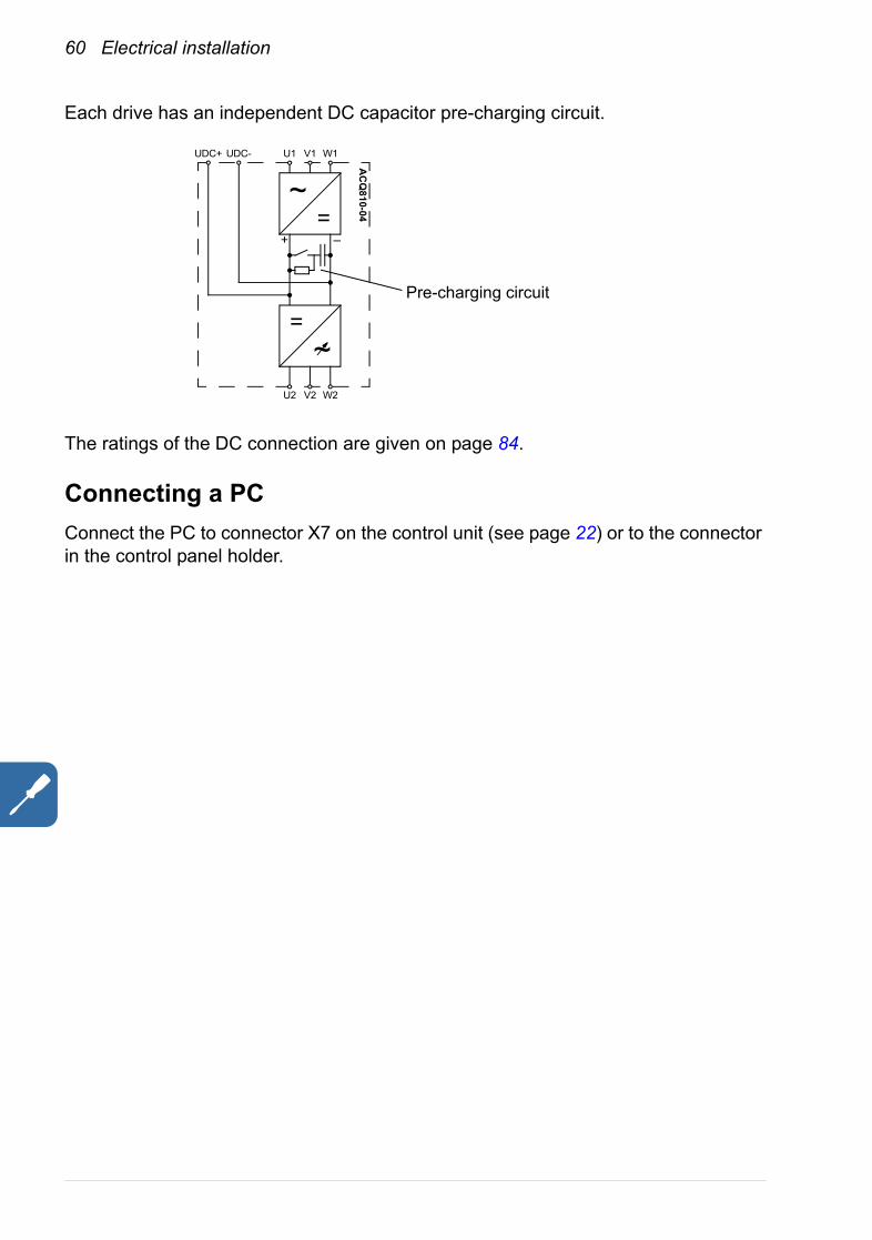
Each drive has an independent DC capacitor pre-charging circuit.
The ratings of the DC connection are given on page 84.
Connecting a PCConnect the PC to connector X7 on the control unit (see page 22) or to the connector in the control panel holder.
~=
+ –
UDC+ UDC- V1 W1U1
~=
V2 W2U2
AC
Q810-04
Pre-charging circuit

Electrical installation 61
Installation of optional modulesOptional modules such as fieldbus adapters and I/O extensions ordered using option codes (see Type designation on page 25) are pre-installed at the factory. Instructions for installing additional modules into the slots on the JCU Control Unit (see page 24 for the available slots) are presented below.
Mechanical installation• Remove the cover assembly from on the JCU Control Unit (refer to page 49).• Remove the protective cover (if present) from the connector of the slot.• Insert the module carefully into its position on the drive.• Fasten the screw.
Note: Correct installation of the screw is essential for fulfilling the EMC requirements and for proper operation of the module.
Electrical installation
See section Grounding and routing the control cables on page 67. See the appropriate option manual for specific installation and wiring instructions.
62 Electrical installation
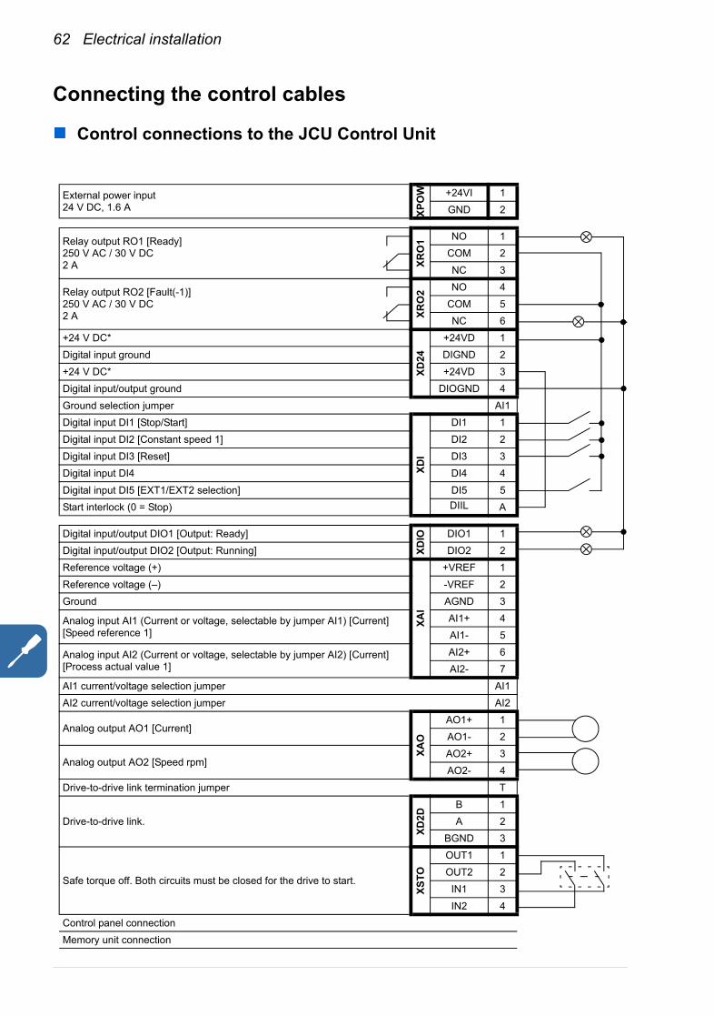
Connecting the control cables
Control connections to the JCU Control Unit
External power input24 V DC, 1.6 A XP
OW +24VI 1
GND 2
Relay output RO1 [Ready]250 V AC / 30 V DC2 A XR
O1 NO 1
COM 2NC 3
Relay output RO2 [Fault(-1)]250 V AC / 30 V DC2 A XR
O2 NO 4
COM 5NC 6
+24 V DC*
XD24
+24VD 1Digital input ground DIGND 2+24 V DC* +24VD 3Digital input/output ground DIOGND 4Ground selection jumper AI1Digital input DI1 [Stop/Start]
XDI
DI1 1Digital input DI2 [Constant speed 1] DI2 2Digital input DI3 [Reset] DI3 3Digital input DI4 DI4 4Digital input DI5 [EXT1/EXT2 selection] DI5 5Start interlock (0 = Stop) DIIL A
Digital input/output DIO1 [Output: Ready]
XDIO DIO1 1
Digital input/output DIO2 [Output: Running] DIO2 2Reference voltage (+)
XAI
+VREF 1Reference voltage (–) -VREF 2Ground AGND 3
Analog input AI1 (Current or voltage, selectable by jumper AI1) [Current] [Speed reference 1]
AI1+ 4AI1- 5
Analog input AI2 (Current or voltage, selectable by jumper AI2) [Current] [Process actual value 1]
AI2+ 6AI2- 7
AI1 current/voltage selection jumper AI1AI2 current/voltage selection jumper AI2
Analog output AO1 [Current]
XAO
AO1+ 1AO1- 2
Analog output AO2 [Speed rpm]AO2+ 3AO2- 4
Drive-to-drive link termination jumper T
Drive-to-drive link.
XD2D
B 1A 2
BGND 3
Safe torque off. Both circuits must be closed for the drive to start.
XSTO
OUT1 1OUT2 2IN1 3IN2 4
Control panel connectionMemory unit connection
Electrical installation 63
XRO1 (3-pole)
XRO2 (3-pole)
XD24 (4-pole)
XDI (6-pole)
DI/DIO ground selection
XDIO (2-pole)
XAI (7-pole)
AI1, AI2
XAO (4-pole)
XD2D (3-pole)
XSTO (4-pole)
XPOW (2-pole)
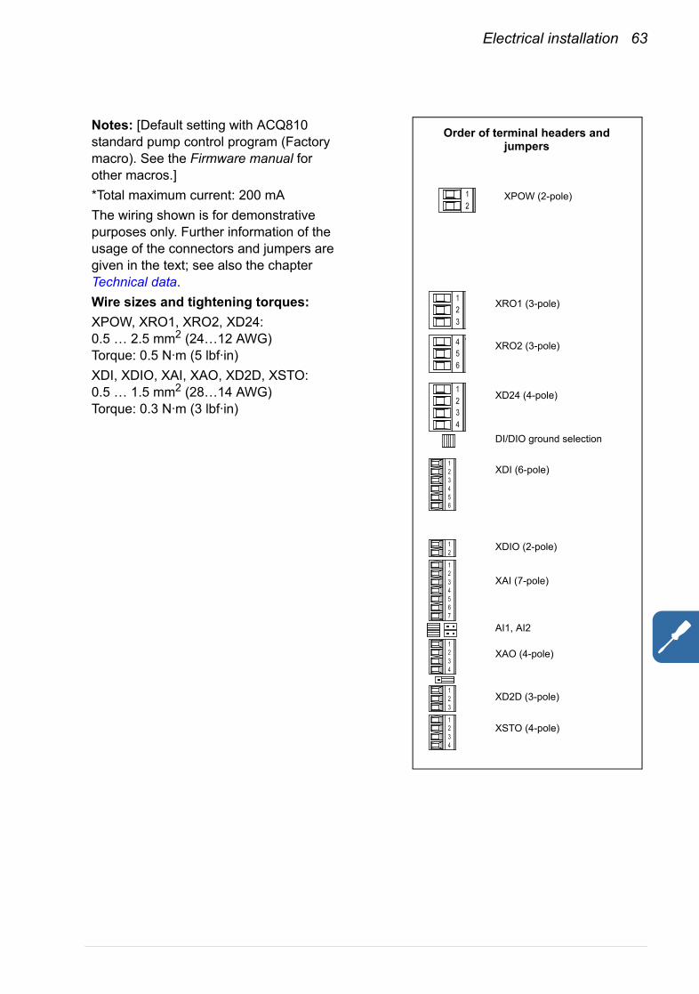
Order of terminal headers and jumpers
Notes: [Default setting with ACQ810 standard pump control program (Factory macro). See the Firmware manual for other macros.]*Total maximum current: 200 mAThe wiring shown is for demonstrative purposes only. Further information of the usage of the connectors and jumpers are given in the text; see also the chapter Technical data.Wire sizes and tightening torques:XPOW, XRO1, XRO2, XD24:0.5 … 2.5 mm2 (24…12 AWG)Torque: 0.5 N·m (5 lbf·in)XDI, XDIO, XAI, XAO, XD2D, XSTO:0.5 … 1.5 mm2 (28…14 AWG)Torque: 0.3 N·m (3 lbf·in)
64 Electrical installation
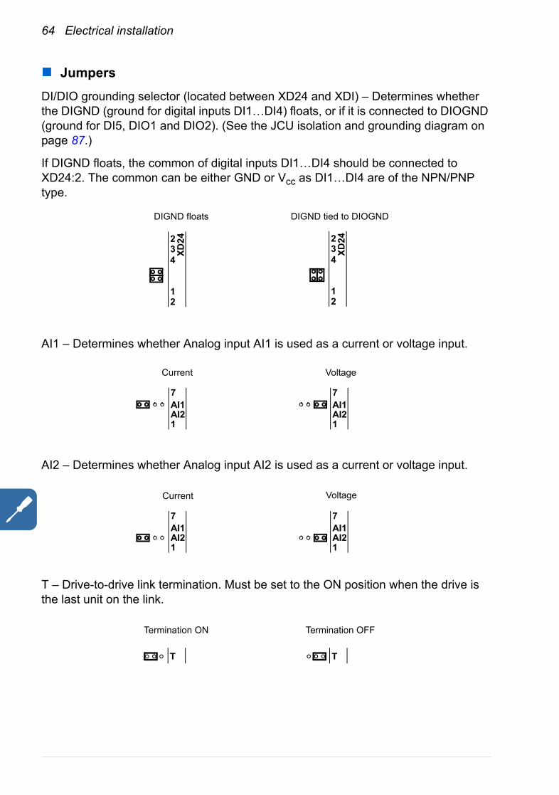
JumpersDI/DIO grounding selector (located between XD24 and XDI) – Determines whether the DIGND (ground for digital inputs DI1…DI4) floats, or if it is connected to DIOGND (ground for DI5, DIO1 and DIO2). (See the JCU isolation and grounding diagram on page 87.)
If DIGND floats, the common of digital inputs DI1…DI4 should be connected to XD24:2. The common can be either GND or Vcc as DI1…DI4 are of the NPN/PNP type.
AI1 – Determines whether Analog input AI1 is used as a current or voltage input.
AI2 – Determines whether Analog input AI2 is used as a current or voltage input.
T – Drive-to-drive link termination. Must be set to the ON position when the drive is the last unit on the link.
1
DIGND floats DIGND tied to DIOGND
XD24
2
4
23
1
XD24
2
4
23
AI1AI21
7AI1AI21
7
Current Voltage
AI1AI21
7AI1AI21
7
Current Voltage
T
Termination ON Termination OFF
T
Electrical installation 65
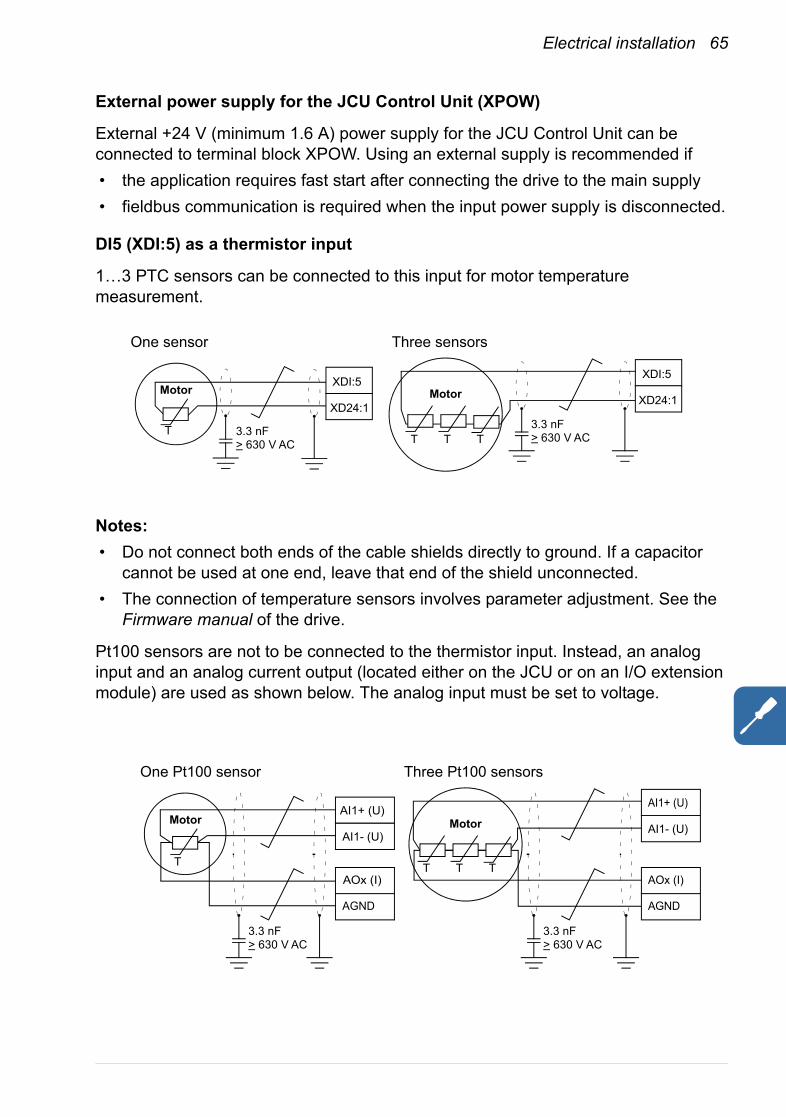
External power supply for the JCU Control Unit (XPOW)
External +24 V (minimum 1.6 A) power supply for the JCU Control Unit can be connected to terminal block XPOW. Using an external supply is recommended if• the application requires fast start after connecting the drive to the main supply• fieldbus communication is required when the input power supply is disconnected.
DI5 (XDI:5) as a thermistor input
1…3 PTC sensors can be connected to this input for motor temperature measurement.
Notes:• Do not connect both ends of the cable shields directly to ground. If a capacitor
cannot be used at one end, leave that end of the shield unconnected.• The connection of temperature sensors involves parameter adjustment. See the
Firmware manual of the drive.
Pt100 sensors are not to be connected to the thermistor input. Instead, an analog input and an analog current output (located either on the JCU or on an I/O extension module) are used as shown below. The analog input must be set to voltage.
Motor
T
Motor
TTT
XDI:5
XD24:13.3 nF> 630 V AC
XDI:5
XD24:1
3.3 nF> 630 V AC
One sensor Three sensors
Motor
T
Motor
TTT
AI1+ (U)
AI1- (U)
3.3 nF> 630 V AC
AOx (I)
AGND
AOx (I)
AGND
AI1+ (U)
AI1- (U)
One Pt100 sensor Three Pt100 sensors
3.3 nF> 630 V AC
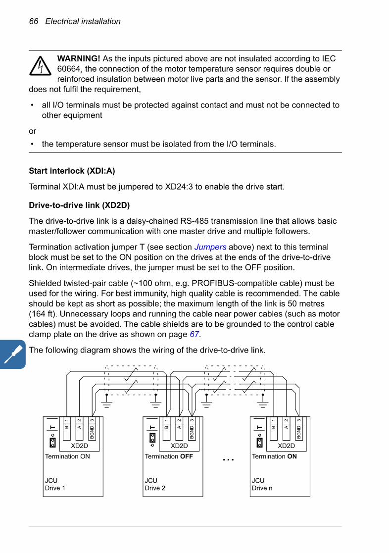
66 Electrical installation
WARNING! As the inputs pictured above are not insulated according to IEC 60664, the connection of the motor temperature sensor requires double or reinforced insulation between motor live parts and the sensor. If the assembly
does not fulfil the requirement,
• all I/O terminals must be protected against contact and must not be connected to other equipment
or• the temperature sensor must be isolated from the I/O terminals.
Start interlock (XDI:A)
Terminal XDI:A must be jumpered to XD24:3 to enable the drive start.
Drive-to-drive link (XD2D)
The drive-to-drive link is a daisy-chained RS-485 transmission line that allows basic master/follower communication with one master drive and multiple followers.
Termination activation jumper T (see section Jumpers above) next to this terminal block must be set to the ON position on the drives at the ends of the drive-to-drive link. On intermediate drives, the jumper must be set to the OFF position.
Shielded twisted-pair cable (~100 ohm, e.g. PROFIBUS-compatible cable) must be used for the wiring. For best immunity, high quality cable is recommended. The cable should be kept as short as possible; the maximum length of the link is 50 metres (164 ft). Unnecessary loops and running the cable near power cables (such as motor cables) must be avoided. The cable shields are to be grounded to the control cable clamp plate on the drive as shown on page 67.
The following diagram shows the wiring of the drive-to-drive link.
XD2D
...
1
T
Termination ON
JCUDrive 1
B
2A
3B
GN
D
XD2D
1
Termination OFF
JCUDrive 2
B
2A
3B
GN
DT
XD2D
1
T
Termination ON
JCUDrive n
B
2A
3B
GN
D
Electrical installation 67
Safe torque off (XSTO)
For the drive to start, both connections (OUT1 to IN1, and OUT2 to IN2) must be closed. By default, the terminal block has jumpers to close the circuit. Remove the jumpers before connecting an external Safe torque off circuitry to the drive. See page 40.
Grounding and routing the control cablesThe shields of all control cables connected to the JCU Control Unit must be grounded at the control cable clamp plate. Use four M4 screws to fasten the plate as shown below left (two of the screws are also used to hold the cover mounting bracket). The plate can be fitted either at the top or bottom of the drive.
Before connecting the wires, run the cables through the cover mounting bracket as shown in the drawing below.
The shields should be continuous as close to the terminals of the JCU as possible. Only remove the outer jacket of the cable at the cable clamp so that the clamp presses on the bare shield. At the terminal block, use shrink tubing or insulating tape to contain any stray strands. The shield (especially in case of multiple shields) can also be terminated with a lug and fastened with a screw at the clamp plate. Leave the other end of the shield unconnected or ground it indirectly via a few nanofarads high-frequency capacitor (e.g. 3.3 nF / 630 V). The shield can also be grounded directly at both ends if they are in the same ground line with no significant voltage drop between the end points.
Keep any signal wire pairs twisted as close to the terminals as possible. Twisting the wire with its return wire reduces disturbances caused by inductive coupling.
Re-install the cover assembly according to the instructions on page 49.
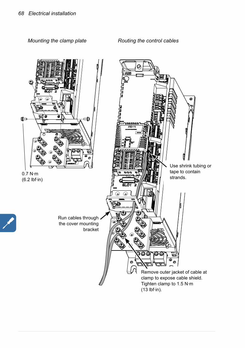
68 Electrical installation
Mounting the clamp plate
Remove outer jacket of cable at clamp to expose cable shield. Tighten clamp to 1.5 N·m (13 lbf·in).
0.7 N·m(6.2 lbf·in)
Routing the control cables
Run cables throughthe cover mounting
bracket
Use shrink tubing or tape to contain strands.

Installation checklist 69
Installation checklist
ChecklistCheck the mechanical and electrical installation of the drive before start-up. Go through the checklist below together with another person. Read the Safety instructions on the first pages of this manual before you work on the unit.
Check
MECHANICAL INSTALLATION
The ambient operating conditions are allowable. (See Mechanical installation, Technical data: Ratings, Ambient conditions.)
The unit is fastened properly to the cabinet. (See Planning the cabinet assembly and Mechanical installation.)
The cooling air will flow freely.
The motor and the driven equipment are ready for start. (See Planning the electrical installation, Technical data: Motor connection.)
ELECTRICAL INSTALLATION (See Planning the electrical installation, Electrical installation.)
The VAR (frames A and B) and EMC/VAR1/VAR2 (frames C and D) screws are removed if the drive is connected to an IT (ungrounded) supply network.
The capacitors are reformed if stored over one year (ask local ABB representative for more information).
The drive is grounded properly.
The supply (input power) voltage matches the drive nominal input voltage.
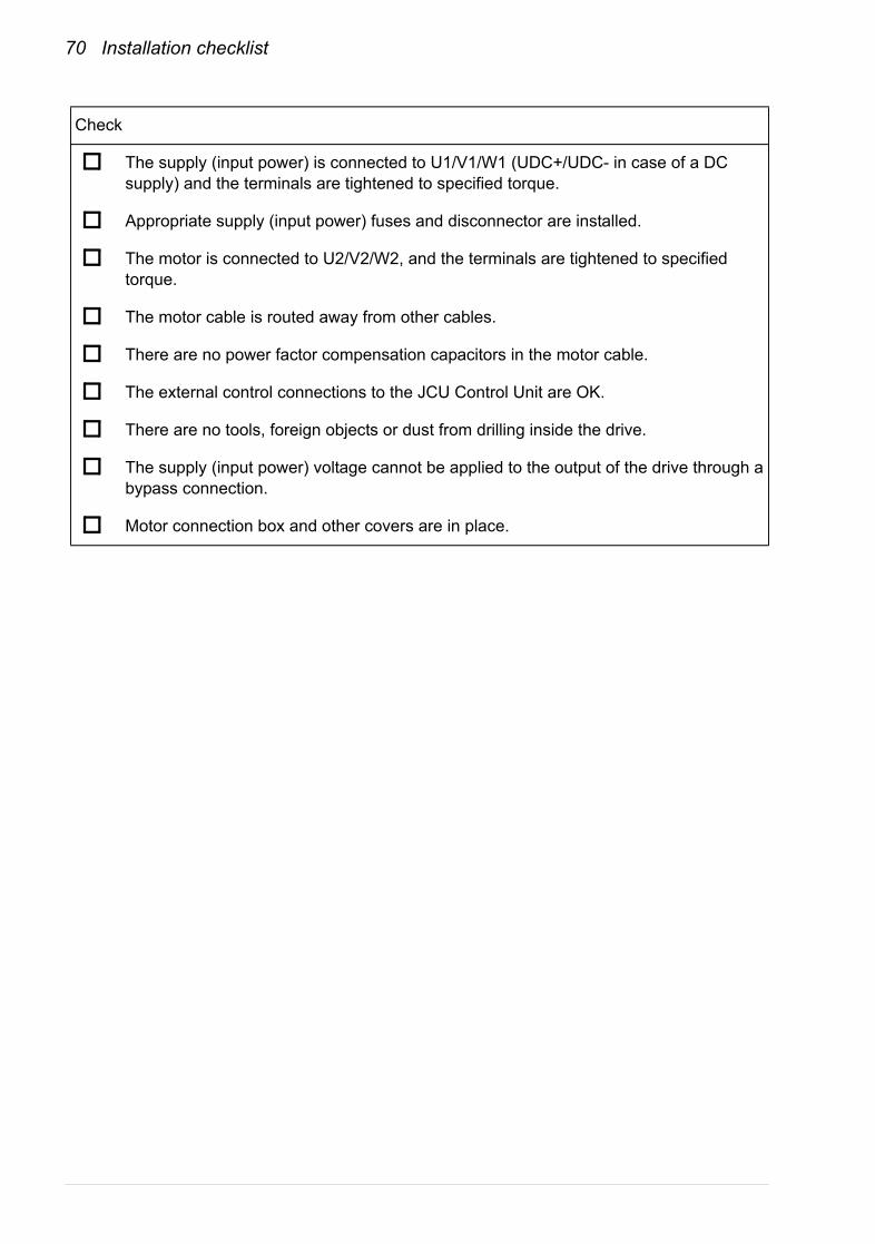
70 Installation checklist
The supply (input power) is connected to U1/V1/W1 (UDC+/UDC- in case of a DC supply) and the terminals are tightened to specified torque.
Appropriate supply (input power) fuses and disconnector are installed.
The motor is connected to U2/V2/W2, and the terminals are tightened to specified torque.
The motor cable is routed away from other cables.
There are no power factor compensation capacitors in the motor cable.
The external control connections to the JCU Control Unit are OK.
There are no tools, foreign objects or dust from drilling inside the drive.
The supply (input power) voltage cannot be applied to the output of the drive through a bypass connection.
Motor connection box and other covers are in place.
Check
Maintenance 71
Maintenance
What this chapter containsThis chapter contains preventive maintenance instructions.
Safety
WARNING! Read the Safety instructions on the first pages of this manual before performing any maintenance on the equipment. Ignoring the safety instructions can cause injury or death.
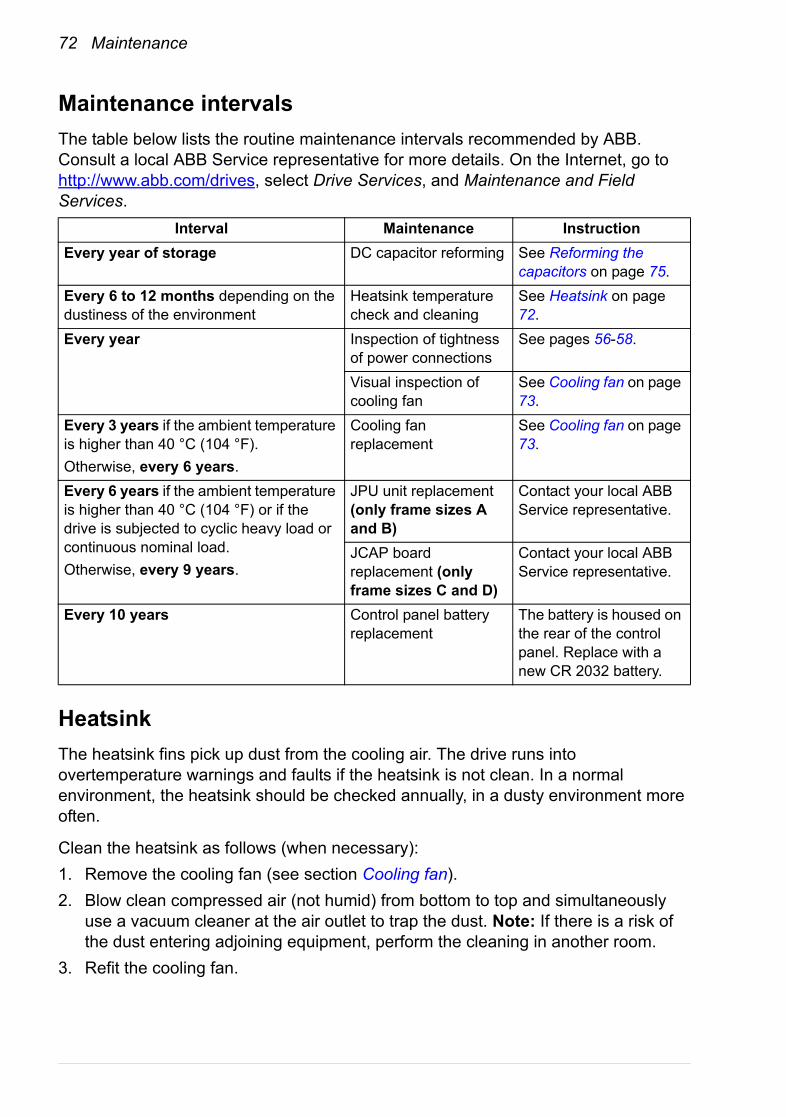
72 Maintenance
Maintenance intervalsThe table below lists the routine maintenance intervals recommended by ABB. Consult a local ABB Service representative for more details. On the Internet, go to http://www.abb.com/drives, select Drive Services, and Maintenance and Field Services.
HeatsinkThe heatsink fins pick up dust from the cooling air. The drive runs into overtemperature warnings and faults if the heatsink is not clean. In a normal environment, the heatsink should be checked annually, in a dusty environment more often.
Clean the heatsink as follows (when necessary):1. Remove the cooling fan (see section Cooling fan).2. Blow clean compressed air (not humid) from bottom to top and simultaneously
use a vacuum cleaner at the air outlet to trap the dust. Note: If there is a risk of the dust entering adjoining equipment, perform the cleaning in another room.
3. Refit the cooling fan.
Interval Maintenance InstructionEvery year of storage DC capacitor reforming See Reforming the
capacitors on page 75.Every 6 to 12 months depending on the dustiness of the environment
Heatsink temperature check and cleaning
See Heatsink on page 72.
Every year Inspection of tightness of power connections
See pages 56-58.
Visual inspection of cooling fan
See Cooling fan on page 73.
Every 3 years if the ambient temperature is higher than 40 °C (104 °F).Otherwise, every 6 years.
Cooling fan replacement
See Cooling fan on page 73.
Every 6 years if the ambient temperature is higher than 40 °C (104 °F) or if the drive is subjected to cyclic heavy load or continuous nominal load.Otherwise, every 9 years.
JPU unit replacement (only frame sizes A and B)
Contact your local ABB Service representative.
JCAP board replacement (only frame sizes C and D)
Contact your local ABB Service representative.
Every 10 years Control panel battery replacement
The battery is housed on the rear of the control panel. Replace with a new CR 2032 battery.
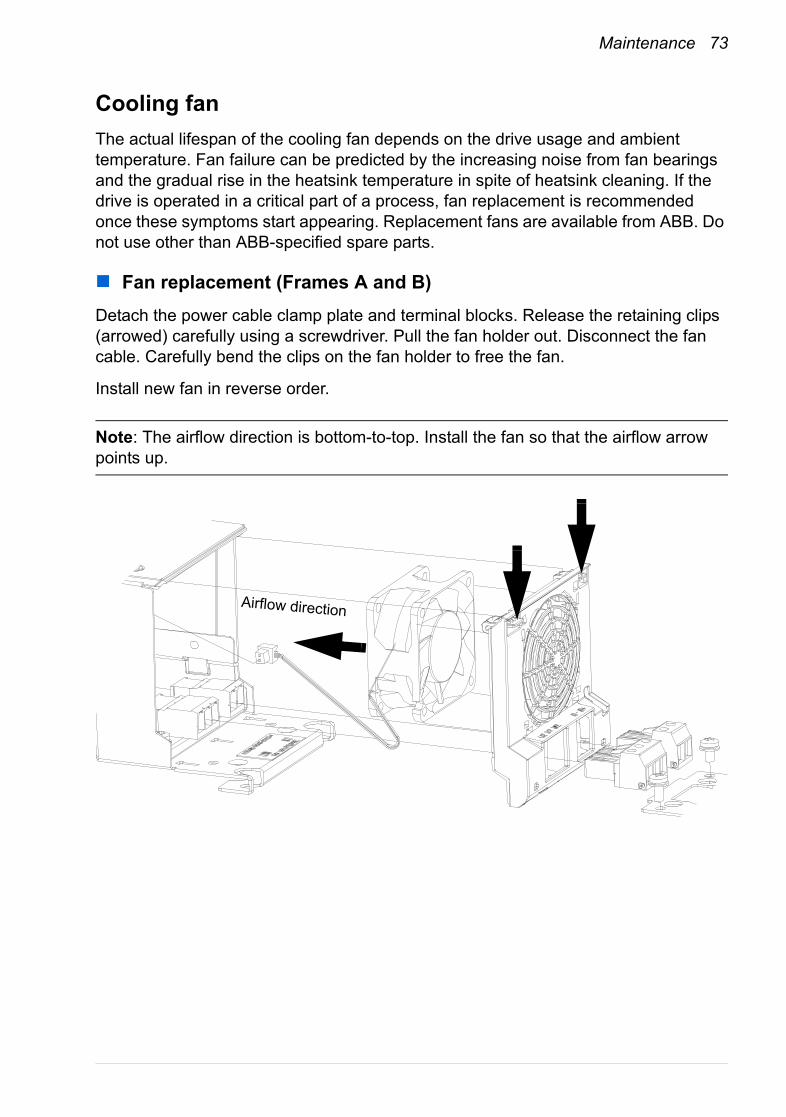
Maintenance 73
Cooling fanThe actual lifespan of the cooling fan depends on the drive usage and ambient temperature. Fan failure can be predicted by the increasing noise from fan bearings and the gradual rise in the heatsink temperature in spite of heatsink cleaning. If the drive is operated in a critical part of a process, fan replacement is recommended once these symptoms start appearing. Replacement fans are available from ABB. Do not use other than ABB-specified spare parts.
Fan replacement (Frames A and B)Detach the power cable clamp plate and terminal blocks. Release the retaining clips (arrowed) carefully using a screwdriver. Pull the fan holder out. Disconnect the fan cable. Carefully bend the clips on the fan holder to free the fan.
Install new fan in reverse order.
Note: The airflow direction is bottom-to-top. Install the fan so that the airflow arrow points up.
Airflow direction
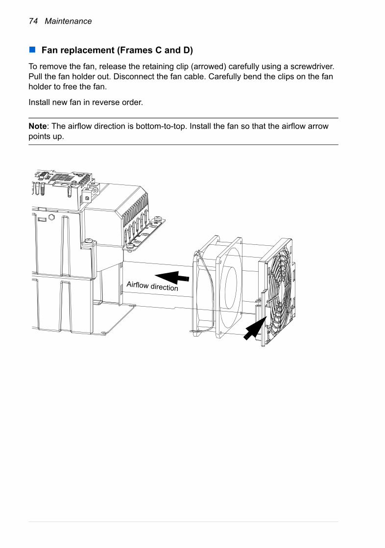
74 Maintenance
Fan replacement (Frames C and D)To remove the fan, release the retaining clip (arrowed) carefully using a screwdriver. Pull the fan holder out. Disconnect the fan cable. Carefully bend the clips on the fan holder to free the fan.
Install new fan in reverse order.
Note: The airflow direction is bottom-to-top. Install the fan so that the airflow arrow points up.
Airflow direction
Maintenance 75
Reforming the capacitorsThe capacitors must be reformed if the drive has been stored for a year or more. See page 35 for information on finding out the manufacturing date. For information on reforming the capacitors, contact your local ABB representative.
Other maintenance actions
Transferring the memory unit to a new drive module
When a drive module is replaced, the parameter settings can be retained by transferring the memory unit from the defective drive module to the new module.
WARNING! Do not remove or insert a memory unit when the drive module is powered.
After power-up, the drive will scan the memory unit. If a different application program or different parameter settings are detected, they are copied to the drive. This takes about 10 to 30 seconds; the drive will not respond while copying is in progress.

76 Maintenance
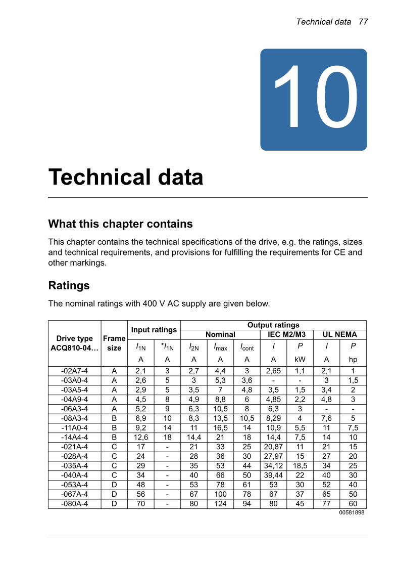
Technical data 77
Technical data
What this chapter containsThis chapter contains the technical specifications of the drive, e.g. the ratings, sizes and technical requirements, and provisions for fulfilling the requirements for CE and other markings.
RatingsThe nominal ratings with 400 V AC supply are given below.
Drive typeACQ810-04…
Frame size
Input ratings Output ratingsNominal IEC M2/M3 UL NEMA
I1N *I1N I2N Imax Icont I P I P
A A A A A A kW A hp-02A7-4 A 2,1 3 2,7 4,4 3 2,65 1,1 2,1 1-03A0-4 A 2,6 5 3 5,3 3,6 - - 3 1,5-03A5-4 A 2,9 5 3,5 7 4,8 3,5 1,5 3,4 2-04A9-4 A 4,5 8 4,9 8,8 6 4,85 2,2 4,8 3-06A3-4 A 5,2 9 6,3 10,5 8 6,3 3 - --08A3-4 B 6,9 10 8,3 13,5 10,5 8,29 4 7,6 5-11A0-4 B 9,2 14 11 16,5 14 10,9 5,5 11 7,5-14A4-4 B 12,6 18 14,4 21 18 14,4 7,5 14 10-021A-4 C 17 - 21 33 25 20,87 11 21 15-028A-4 C 24 - 28 36 30 27,97 15 27 20-035A-4 C 29 - 35 53 44 34,12 18,5 34 25-040A-4 C 34 - 40 66 50 39,44 22 40 30-053A-4 D 48 - 53 78 61 53 30 52 40-067A-4 D 56 - 67 100 78 67 37 65 50-080A-4 D 70 - 80 124 94 80 45 77 60
00581898

78 Technical data
DeratingThe continuous output currents stated above must be derated if any of the following conditions apply:• the ambient temperature exceeds +40 °C (+104 °F)• the drive is installed higher than 1000 m above sea level.
Note: The final derating factor is a multiplication of all applicable derating factors.
Ambient temperature derating
In the temperature range +40…55 °C (+104…131 °F), the rated output current is derated by 1% for every added 1 °C (1.8 °F) as follows:
I1N Nominal input current (rms)*Without mains choke.
I2N Nominal output current. 110% overload 1 min / 5 min.Imax Maximum output current. Available for 10 seconds at start, otherwise as long as
allowed by drive temperature.Icont Continuous rms output current with no overload capacityP Typical motor powerNote 1: The ratings apply at an ambient temperature of 40 °C (+104 °F). In lower temperatures the ratings are higher (except Imax).Note 2: To achieve the rated motor power given in the table, the rated current of the drive must be higher than or equal to the rated motor current.The DriveSize dimensioning tool available from ABB is recommended for selecting the drive, motor and gear combination.
Ambient temperature
Derating factor
1.00
0.85
+40 °C +55 °C+104 °F +131 °F

Technical data 79
The continuous rms output currents with no overload capacity at different ambient temperatures (45 °C, 50 °C and 55 °C) are given below.
Altitude derating
At altitudes from 1000 to 4000 m (3300 to 13123 ft) above sea level, the derating is 1% for every 100 m (328 ft). For a more accurate derating, use the DriveSize PC tool.
Note: If the installation site is higher than 2000 m (6600 ft) above sea level, connection of the drive to an ungrounded (IT) or corner-grounded delta network is not allowed.
Drive typeACQ810-04-… Frame size
Icont45A
Icont50A
Icont55A
-02A7-4 A 2,9 2,7 2,6-03A0-4 A 3,4 3,2 3,1-03A5-4 A 4,6 4,3 4,1-04A9-4 A 5,7 5,4 5,1-06A3-4 A 7,6 7,2 6,8-08A3-4 B 10 9,5 8,9-11A0-4 B 13,3 12,6 11,9-14A4-4 B 17,1 16,2 15,3-021A-4 C 24 23 21-028A-4 C 29 27 26-035A-4 C 42 40 37-040A-4 C 48 45 43-053A-4 D 58 55 52-067A-4 D 74 70 66-080A-4 D 89 85 80
00581898
Icontxx Continuous rms output current at specified temperature maximum, no overloading
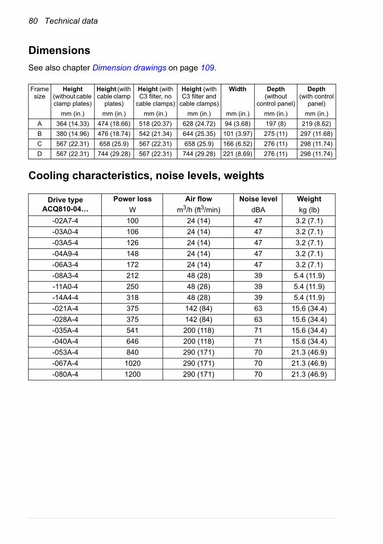
80 Technical data
DimensionsSee also chapter Dimension drawings on page 109.
Cooling characteristics, noise levels, weights
Frame size
Height (without cable clamp plates)
Height (with cable clamp
plates)
Height (with C3 filter, no
cable clamps)
Height (with C3 filter and
cable clamps)
Width Depth (without
control panel)
Depth (with control
panel)mm (in.) mm (in.) mm (in.) mm (in.) mm (in.) mm (in.) mm (in.)
A 364 (14.33) 474 (18.66) 518 (20.37) 628 (24.72) 94 (3.68) 197 (8) 219 (8.62)B 380 (14.96) 476 (18.74) 542 (21.34) 644 (25.35) 101 (3.97) 275 (11) 297 (11.68)C 567 (22.31) 658 (25.9) 567 (22.31) 658 (25.9) 166 (6.52) 276 (11) 298 (11.74)D 567 (22.31) 744 (29.28) 567 (22.31) 744 (29.28) 221 (8.69) 276 (11) 298 (11.74)
Drive typeACQ810-04…
Power lossW
Air flowm3/h (ft3/min)
Noise leveldBA
Weightkg (lb)
-02A7-4 100 24 (14) 47 3.2 (7.1)-03A0-4 106 24 (14) 47 3.2 (7.1)-03A5-4 126 24 (14) 47 3.2 (7.1)-04A9-4 148 24 (14) 47 3.2 (7.1)-06A3-4 172 24 (14) 47 3.2 (7.1)-08A3-4 212 48 (28) 39 5.4 (11.9)-11A0-4 250 48 (28) 39 5.4 (11.9)-14A4-4 318 48 (28) 39 5.4 (11.9)-021A-4 375 142 (84) 63 15.6 (34.4)-028A-4 375 142 (84) 63 15.6 (34.4)-035A-4 541 200 (118) 71 15.6 (34.4)-040A-4 646 200 (118) 71 15.6 (34.4)-053A-4 840 290 (171) 70 21.3 (46.9)-067A-4 1020 290 (171) 70 21.3 (46.9)-080A-4 1200 290 (171) 70 21.3 (46.9)
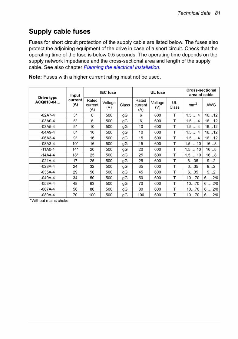
Technical data 81
Supply cable fusesFuses for short circuit protection of the supply cable are listed below. The fuses also protect the adjoining equipment of the drive in case of a short circuit. Check that the operating time of the fuse is below 0.5 seconds. The operating time depends on the supply network impedance and the cross-sectional area and length of the supply cable. See also chapter Planning the electrical installation.
Note: Fuses with a higher current rating must not be used.
Drive typeACQ810-04…
Input current
(A)
IEC fuse UL fuse Cross-sectional area of cable
Rated current
(A)
Voltage (V) Class
Rated current
(A)
Voltage (V)
UL Class mm2 AWG
-02A7-4 3* 6 500 gG 6 600 T 1.5 … 4 16…12-03A0-4 5* 6 500 gG 6 600 T 1.5 … 4 16…12-03A5-4 5* 10 500 gG 10 600 T 1.5 … 4 16…12-04A9-4 8* 10 500 gG 10 600 T 1.5 … 4 16…12-06A3-4 9* 16 500 gG 15 600 T 1.5 … 4 16…12-08A3-4 10* 16 500 gG 15 600 T 1.5 … 10 16…8-11A0-4 14* 20 500 gG 20 600 T 1.5 … 10 16…8-14A4-4 18* 25 500 gG 25 600 T 1.5 … 10 16…8-021A-4 17 25 500 gG 25 600 T 6…35 9…2-028A-4 24 32 500 gG 35 600 T 6…35 9…2-035A-4 29 50 500 gG 45 600 T 6…35 9…2-040A-4 34 50 500 gG 50 600 T 10…70 6 … 2/0-053A-4 48 63 500 gG 70 600 T 10…70 6 … 2/0-067A-4 56 80 500 gG 80 600 T 10…70 6 … 2/0-080A-4 70 100 500 gG 100 600 T 10…70 6 … 2/0
*Without mains choke
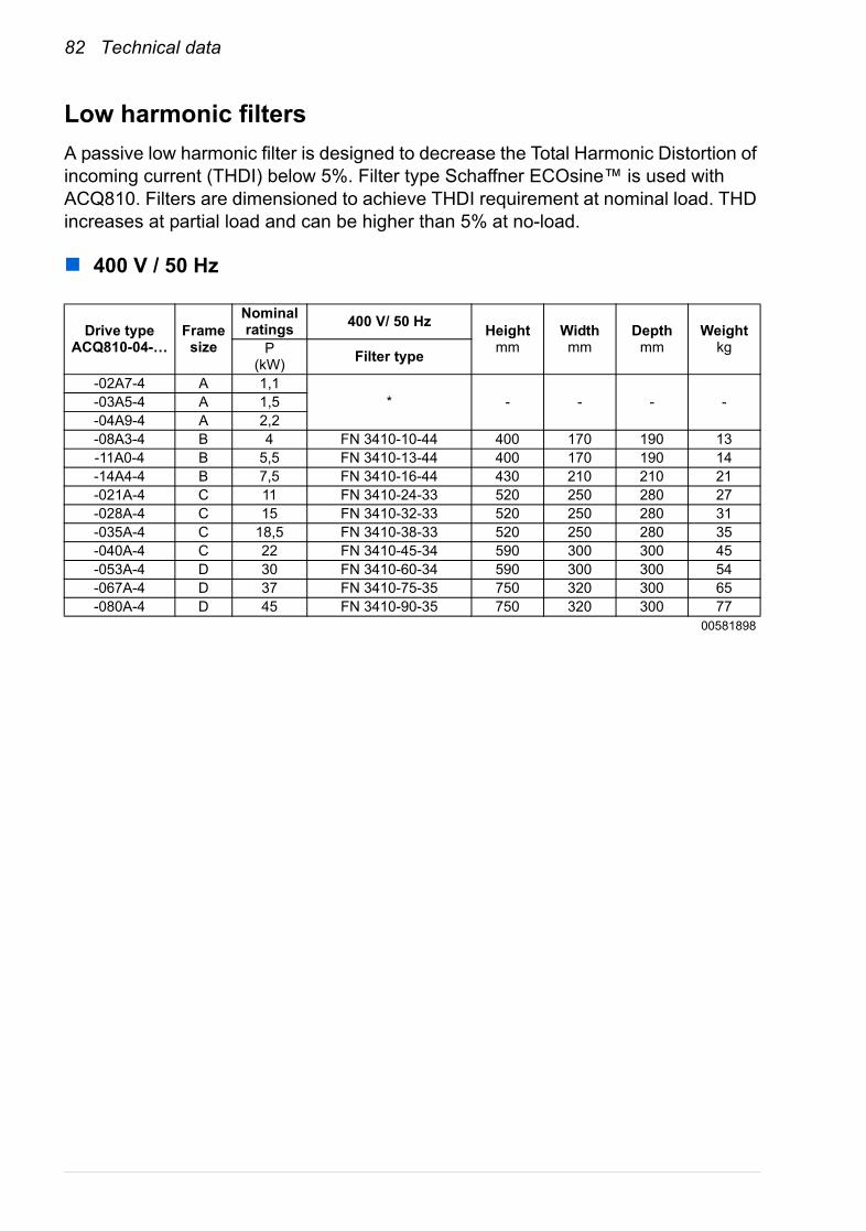
82 Technical data
Low harmonic filtersA passive low harmonic filter is designed to decrease the Total Harmonic Distortion of incoming current (THDI) below 5%. Filter type Schaffner ECOsine™ is used with ACQ810. Filters are dimensioned to achieve THDI requirement at nominal load. THD increases at partial load and can be higher than 5% at no-load.
400 V / 50 Hz
Drive typeACQ810-04-…
Frame size
Nominal ratings 400 V/ 50 Hz Height
mmWidthmm
Depthmm
WeightkgP
(kW) Filter type
-02A7-4 A 1,1* - - - --03A5-4 A 1,5
-04A9-4 A 2,2-08A3-4 B 4 FN 3410-10-44 400 170 190 13-11A0-4 B 5,5 FN 3410-13-44 400 170 190 14-14A4-4 B 7,5 FN 3410-16-44 430 210 210 21-021A-4 C 11 FN 3410-24-33 520 250 280 27-028A-4 C 15 FN 3410-32-33 520 250 280 31-035A-4 C 18,5 FN 3410-38-33 520 250 280 35-040A-4 C 22 FN 3410-45-34 590 300 300 45-053A-4 D 30 FN 3410-60-34 590 300 300 54-067A-4 D 37 FN 3410-75-35 750 320 300 65-080A-4 D 45 FN 3410-90-35 750 320 300 77
00581898

Technical data 83
460 V / 60 Hz
Note: If the supply voltage is 480 V, one step smaller filter must be used at the same power. E.g. at supply voltage 400 V and power 11 kW the filter selection is FN 3410-24-33, but at 480 V and 11 kW the selection is FN 3410-16-44.
For further information, see www.schaffner.com or contact your local ABB office.
Drive typeACQ810-04-…
Frame size
Nominal ratings 460 V / 60 Hz Height
mmWidthmm
Depthmm
WeightkgP
(hp) Filter type
-02A7-4 A 1
* - - - --03A0-4 A 1,5-03A5-4 A 2-04A9-4 A 3-08A3-4 B 5 FN 3412-8-44 400 170 190 12-11A0-4 B 7,5 FN 3412-11-44 400 170 190 13-14A4-4 B 10 FN 3412-15-44 430 210 210 17-021A-4 C 15 FN 3412-21-44 430 210 210 21-028A-4 C 20 FN 3412-28-33 520 250 280 28-035A-4 C 25 FN 3412-35-33 520 250 280 32-040A-4 C 30 FN 3412-41-33 520 250 280 45-053A-4 D 40 FN 3412-53-34 590 300 300 48-067A-4 D 50 FN 3412-65-34 590 300 300 52-080A-4 D 60 FN 3412-80-35 750 320 300 69
00581898* Smallest filter is for power 4 kW. This filter can be used at lower power, but the THD of the line current will increase. E.g. at power 1,1 kW THDI is approximately 12% when using filter type FN3410-10-44.
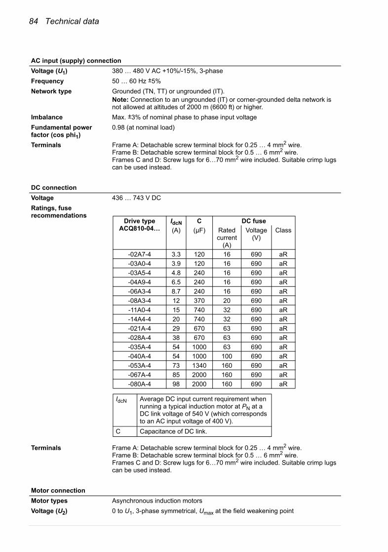
84 Technical data
AC input (supply) connectionVoltage (U1) 380 … 480 V AC +10%/-15%, 3-phaseFrequency 50 … 60 Hz ±5%Network type Grounded (TN, TT) or ungrounded (IT).
Note: Connection to an ungrounded (IT) or corner-grounded delta network is not allowed at altitudes of 2000 m (6600 ft) or higher.
Imbalance Max. ±3% of nominal phase to phase input voltageFundamental power factor (cos phi1)
0.98 (at nominal load)
Terminals Frame A: Detachable screw terminal block for 0.25 … 4 mm2 wire.Frame B: Detachable screw terminal block for 0.5 … 6 mm2 wire.Frames C and D: Screw lugs for 6…70 mm2 wire included. Suitable crimp lugs can be used instead.
DC connectionVoltage 436 … 743 V DCRatings, fuse recommendations
Terminals Frame A: Detachable screw terminal block for 0.25 … 4 mm2 wire.Frame B: Detachable screw terminal block for 0.5 … 6 mm2 wire.Frames C and D: Screw lugs for 6…70 mm2 wire included. Suitable crimp lugs can be used instead.
Motor connectionMotor types Asynchronous induction motorsVoltage (U2) 0 to U1, 3-phase symmetrical, Umax at the field weakening point
Drive typeACQ810-04…
IdcN C DC fuse(A) (µF) Rated
current (A)
Voltage (V)
Class
-02A7-4 3.3 120 16 690 aR-03A0-4 3.9 120 16 690 aR-03A5-4 4.8 240 16 690 aR-04A9-4 6.5 240 16 690 aR-06A3-4 8.7 240 16 690 aR-08A3-4 12 370 20 690 aR-11A0-4 15 740 32 690 aR-14A4-4 20 740 32 690 aR-021A-4 29 670 63 690 aR-028A-4 38 670 63 690 aR-035A-4 54 1000 63 690 aR-040A-4 54 1000 100 690 aR-053A-4 73 1340 160 690 aR-067A-4 85 2000 160 690 aR-080A-4 98 2000 160 690 aR
IdcN Average DC input current requirement when running a typical induction motor at PN at a DC link voltage of 540 V (which corresponds to an AC input voltage of 400 V).
C Capacitance of DC link.

Technical data 85
Frequency 0 … 500 HzCurrent See section Ratings.Switching frequency 3 kHz as default.Maximum motor cable length
Frames A and B: 150 m (492 ft) *Frames C and D: 300 m (984 ft) **100 m with EN 61800-3 Category C3 filterNote: With motor cables longer than 100 m (328 ft) the EMC Directive requirements may not be fulfilled.
Terminals Frame A: Detachable screw terminal block for 0.25 … 4 mm2 wire.Frame B: Detachable screw terminal block for 0.5 … 6 mm2 wire.Frames C and D: Screw lugs for 6…70 mm2 wire included. Suitable crimp lugs can be used instead.
JCU Control UnitPower supply 24 V (±10%) DC, 1.6 A
Supplied from the power unit of the drive, or from an external power supply through connector XPOW (pitch 5 mm, wire size 2.5 mm2).
Relay outputs RO1…RO2 (XRO1 … XRO2)
Connector pitch 5 mm, wire size 2.5 mm2
250 V AC / 30 V DC, 2 AProtected by varistorsNote: At installation sites between 2000 meters (6562 feet) and 4000 meters (13123 feet), the Protective Extra Low Voltage (PELV) requirements are not fulfilled if a relay output is used with a voltage greater than 48 V.
+24 V output(XD24)
Connector pitch 5 mm, wire size 2.5 mm2
Digital inputs DI1…DI5 (XDI:1 … XDI:5)
Connector pitch 3.5 mm, wire size 1.5 mm2
24 V logic levels: “0” < 5 V, “1” > 15 VRin: 2.0 kohmInput type: NPN/PNP (DI1…DI4), NPN (DI5)Filtering: 0.25 msDI5 (XDI:5) can alternatively be used as an input for 1…3 PTC thermistors.“0” > 4 kohm, “1” < 1.5 kohmImax: 15 mA
Start interlock input DIIL(XDI:A)
Wire size 1.5 mm2
24 V logic levels: “0” < 5 V, “1” > 15 VRin: 2.0 kohmInput type: NPN/PNPFiltering: 0.25 ms
Digital inputs/outputs DIO1 and DIO2 (XDIO:1 and XDIO:2)Input/output mode selection by parameters.DIO1 can be configured as a frequency input (0…16 kHz) for 24 V level square wave signal (sinusoidal or other wave form cannot be used). DIO2 can be configured as a 24 V level square wave frequency output. See the Firmware manual, parameter group 12.
Connector pitch 3.5 mm, wire size 1.5 mm2
As inputs:24 V logic levels: “0” < 5 V, “1” > 15 VRin: 2.0 kohmFiltering: 0.25 msAs outputs:Total output current limited by auxiliary voltage outputs to 200 mAOutput type: Open emitter
RL
VCC
DIOx
DGND

86 Technical data
Reference voltage for analog inputs +VREF and -VREF(XAI:1 and XAI:2)
Connector pitch 3.5 mm, wire size 1.5 mm2
10 V ±1% and –10 V ±1%, Rload > 1 kohm
Analog inputs AI1 and AI2 (XAI:4 … XAI:7).Current/voltage input mode selection by jumpers. See page 64.
Connector pitch 3.5 mm, wire size 1.5 mm2
Current input: –20…20 mA, Rin: 100 ohmVoltage input: –10…10 V, Rin: 200 kohmDifferential inputs, common mode ±20 VSampling interval per channel: 0.25 msFiltering: 0.25 msResolution: 11 bit + sign bitInaccuracy: 1% of full scale range
Analog outputs AO1 and AO2(XAO)
Connector pitch 3.5 mm, wire size 1.5 mm2
0…20 mA, Rload < 500 ohmFrequency range: 0…800 HzResolution: 11 bit + sign bitInaccuracy: 2% of full scale range
Drive to drive link(XD2D)
Connector pitch 3.5 mm, wire size 1.5 mm2
Physical layer: RS-485Termination by jumper
Safe torque off connection (XSTO)
Connector pitch 3.5 mm, wire size 1.5 mm2
For the drive to start, both connections (OUT1 to IN1, and OUT2 to IN2) must be closed
Control panel / PC connection
Connector: RJ-45Cable length < 3 m
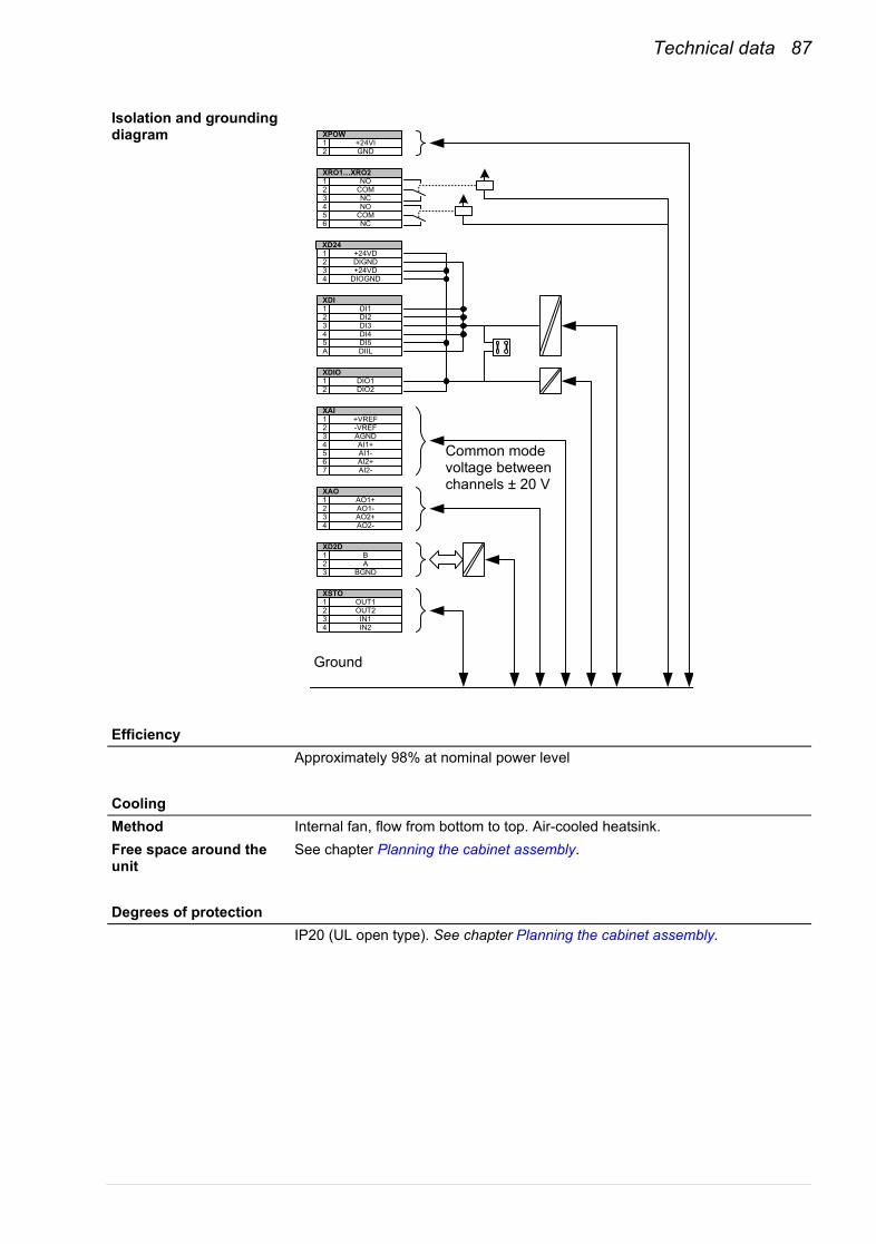
Technical data 87
Isolation and grounding diagram
EfficiencyApproximately 98% at nominal power level
CoolingMethod Internal fan, flow from bottom to top. Air-cooled heatsink.Free space around the unit
See chapter Planning the cabinet assembly.
Degrees of protectionIP20 (UL open type). See chapter Planning the cabinet assembly.
+24VIGND
NOCOMNC
12
123
NOCOMNC
456
+24VDDIGND+24VD
123
DIOGND4
DI1DI2
XDI12
DI33DI4DI5
45
DIILA
DIO1DIO2
12
+VREF-VREFAGND
123
AI1+4AI1-AI2+
56
AI2-7
AO1+AO1-AO2+
123
AO2-4
BA
BGND
123
OUT1OUT2IN1
123
IN24
XPOW
XRO1…XRO2
XD24
XDIO
XAI
XAO
XD2D
XSTO
Common mode voltage between channels ± 20 V
Ground
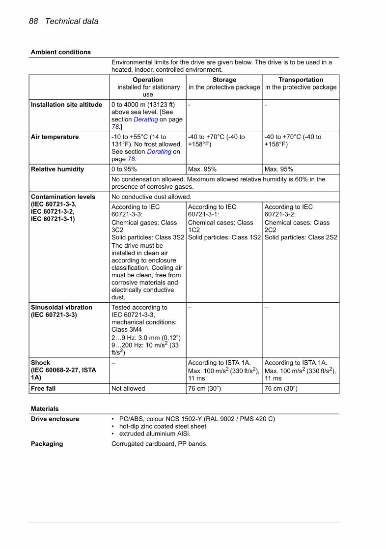
88 Technical data
Ambient conditionsEnvironmental limits for the drive are given below. The drive is to be used in a heated, indoor, controlled environment.
Operation installed for stationary
use
Storagein the protective package
Transportationin the protective package
Installation site altitude 0 to 4000 m (13123 ft) above sea level. [See section Derating on page 78.]
- -
Air temperature -10 to +55°C (14 to 131°F). No frost allowed. See section Derating on page 78.
-40 to +70°C (-40 to +158°F)
-40 to +70°C (-40 to +158°F)
Relative humidity 0 to 95% Max. 95% Max. 95%No condensation allowed. Maximum allowed relative humidity is 60% in the presence of corrosive gases.
Contamination levels (IEC 60721-3-3, IEC 60721-3-2, IEC 60721-3-1)
No conductive dust allowed.According to IEC 60721-3-3:Chemical gases: Class 3C2Solid particles: Class 3S2The drive must be installed in clean air according to enclosure classification. Cooling air must be clean, free from corrosive materials and electrically conductive dust.
According to IEC 60721-3-1:Chemical cases: Class 1C2Solid particles: Class 1S2
According to IEC 60721-3-2:Chemical cases: Class 2C2Solid particles: Class 2S2
Sinusoidal vibration (IEC 60721-3-3)
Tested according to IEC 60721-3-3, mechanical conditions: Class 3M42…9 Hz: 3.0 mm (0.12”)9…200 Hz: 10 m/s2 (33 ft/s2)
– –
Shock (IEC 60068-2-27, ISTA 1A)
– According to ISTA 1A.Max. 100 m/s2 (330 ft/s2), 11 ms
According to ISTA 1A.Max. 100 m/s2 (330 ft/s2), 11 ms
Free fall Not allowed 76 cm (30”) 76 cm (30”)
MaterialsDrive enclosure • PC/ABS, colour NCS 1502-Y (RAL 9002 / PMS 420 C)
• hot-dip zinc coated steel sheet• extruded aluminium AlSi.
Packaging Corrugated cardboard, PP bands.
Technical data 89
Disposal The drive contains raw materials that should be recycled to preserve energy and natural resources. The package materials are environmentally compatible and recyclable. All metal parts can be recycled. The plastic parts can either be recycled or burned under controlled circumstances, according to local regulations. Most recyclable parts are marked with recycling marks.If recycling is not feasible, all parts excluding electrolytic capacitors and printed circuit boards can be landfilled. The DC capacitors contain electrolyte, which is classified as hazardous waste within the EU. They must be removed and handled according to local regulations.For further information on environmental aspects and more detailed recycling instructions, please contact your local ABB distributor.
Applicable standardsThe drive complies with the following standards. The compliance with the European Low Voltage Directive is verified according to standards EN 50178 and EN 60204-1.
• EN 50178:1997 Electronic equipment for use in power installations• IEC 60204-1:2006 Safety of machinery. Electrical equipment of machines. Part 1: General
requirements. Provisions for compliance: The final assembler of the machine is responsible for installing - an emergency-stop device - a supply disconnecting device- the drive module into a cabinet.
• EN 60529:1991 (IEC 60529)
Degrees of protection provided by enclosures (IP code)
• IEC 60664-1:2007 Insulation coordination for equipment within low-voltage systems. Part 1: Principles, requirements and tests.
• IEC/EN 61000-3-12:2004
Electromagnetic compatibility (EMC). Part 3-12: Limits. Limits for harmonic currents produced by equipment connected to public low-voltage systems with input current >16 A and <75 A per phase. Provisions for compliance:- With converters ACQ810-04-14A4-4…021A-4 IEC61000-3-12 is fulfilled with short-circuit-ratio >120 and supply short-circuit current <3.6 kA- With converters ACQ810-04-028A-4…080A-4 IEC61000-3-12 is fulfilled with short-circuit-ratio >120 and supply short-circuit current <14 kA.Short-circuit-ratio is defined as a ratio of supply short-circuit current and converter’s incoming current.
• EN 61800-3:2004 Adjustable speed electrical power drive systems. Part 3: EMC requirements and specific test methods.
• EN 61800-5-1:2003 Adjustable speed electrical power drive systems.Part 5-1: Safety requirements. Electrical, thermal and energyProvisions for compliance: The final assembler of the machine is responsible for installing the ACQ810-04 in a cabinet that is protected to IP3X for top surfaces for vertical access.
• EN 61800-5-2:2007 Adjustable speed electrical power drive systems.Part 5-2: Safety requirements – Functional
• UL 508C:2002, Third Edition
UL Standard for Safety, Power Conversion Equipment
• NEMA 250:2003 Enclosures for Electrical Equipment (1000 Volts Maximum)• CSA C22.2 No. 14-05
(2005)Industrial Control Equipment

90 Technical data
CE markingA CE mark is attached to the drive to verify that the drive follows the provisions of the European Low Voltage and EMC Directives.
Compliance with the European Low Voltage DirectiveThe compliance with the European Low Voltage Directive has been verified according to standards EN 50178, EN 61800-5-1 and EN 60204-1.
Compliance with the European EMC DirectiveThe cabinet builder is in responsible for the compliance of the drive system with the European EMC Directive. For information on items to consider, see:
• Subsections Compliance with EN 61800-3:2004, category C2; Compliance with EN 61800-3:2004, category C3; and Compliance with EN 61800-3:2004, category C4 below
• The chapter Planning the electrical installation in this manual• Technical Guide No. 3 – EMC Compliant Installation and Configuration for a
Power Drive System [3AFE61348280 (English)].
Definitions
EMC stands for Electromagnetic Compatibility. It is the ability of electrical/electronic equipment to operate without problems within an electromagnetic environment. Likewise, the equipment must not disturb or interfere with any other product or system within its locality.
First environment includes domestic premises. It also includes establishments directly connected without intermediate transformers to a low-voltage network which supplies buildings used for domestic purposes.
Second environment includes all establishments other than those directly connected to a low-voltage network which supplies buildings used for domestic purposes.
Drive of category C2. Power drive system with rated voltage less than 1000 V which is neither a plug-in device nor a movable device and, when used in the first environment, is intended to be installed and commissioned only by a professional.
Drive of category C3. Power drive system with rated voltage less than 1000 V, intended for use in the second environment and not intended for use in the first environment.
Drive of category C4. Power drive system with rated voltage equal to or above 1000 V, or rated current equal to or above 400 A, or intended for use in complex systems in the second environment.
Technical data 91
Compliance with EN 61800-3:2004, category C2
The drive meets the requirements of the EMC Directive with the following provisions:
1. The drive is equipped with external EMC filter JFI-0x.2. The motor and control cables are selected as specified in the chapter Planning
the electrical installation.3. The drive is installed according to the instructions given in this manual.4. Motor cable length does not exceed 100 metres (328 ft).
Note: It is not allowed to use the optional EMC filter on IT (ungrounded) systems. The supply network becomes connected to ground potential through the EMC filter capacitors which may cause danger or damage the drive.
Note: It is not allowed to use the optional EMC filter on a corner-grounded TN system as this would damage the drive.
WARNING! The drive may cause radio interference if used in a residential or domestic environment. The user is required to take measures to prevent interference, in addition to the requirements for CE compliance listed above, if
necessary.
Compliance with EN 61800-3:2004, category C3
The drive meets the requirements of the EMC Directive with the following provisions:
1. The motor and control cables are selected as specified in the chapter Planning the electrical installation.
2. The drive is installed according to the instructions given in this manual.3. Motor cable length does not exceed 100 metres (328 ft).
Compliance with EN 61800-3:2004, category C4
The drive meets the requirements of the EMC Directive with the following provisions:
1. The drive is equipped with filtering option +0E200.2. It is ensured that no excessive emission is propagated to neighbouring low-
voltage networks. In some cases, the natural suppression in transformers and cables is sufficient. If in doubt, a supply transformer with static screening between the primary and secondary windings can be used.
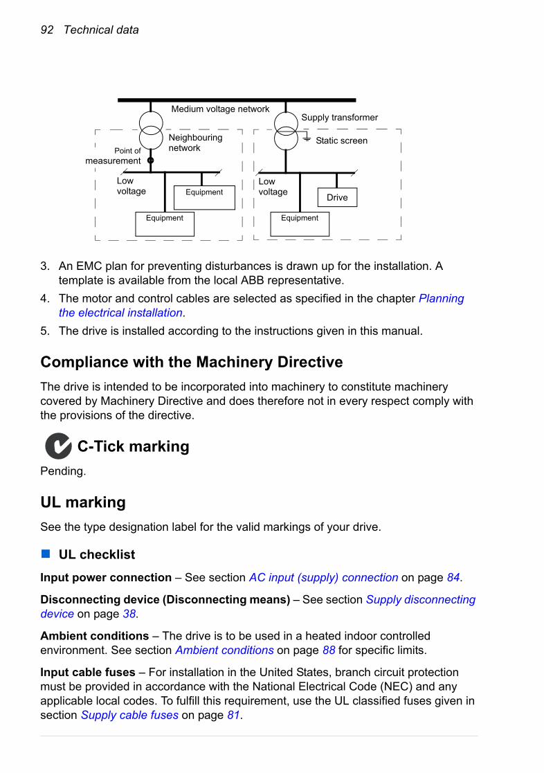
92 Technical data
3. An EMC plan for preventing disturbances is drawn up for the installation. A template is available from the local ABB representative.
4. The motor and control cables are selected as specified in the chapter Planning the electrical installation.
5. The drive is installed according to the instructions given in this manual.
Compliance with the Machinery DirectiveThe drive is intended to be incorporated into machinery to constitute machinery covered by Machinery Directive and does therefore not in every respect comply with the provisions of the directive.
C-Tick markingPending.
UL markingSee the type designation label for the valid markings of your drive.
UL checklistInput power connection – See section AC input (supply) connection on page 84.
Disconnecting device (Disconnecting means) – See section Supply disconnecting device on page 38.
Ambient conditions – The drive is to be used in a heated indoor controlled environment. See section Ambient conditions on page 88 for specific limits.
Input cable fuses – For installation in the United States, branch circuit protection must be provided in accordance with the National Electrical Code (NEC) and any applicable local codes. To fulfill this requirement, use the UL classified fuses given in section Supply cable fuses on page 81.
Low voltage
Low voltage
Equipment
Supply transformerMedium voltage network
Static screenPoint of
measurement
Drive
Neighbouring network
Equipment
Equipment

Technical data 93
For installation in Canada, branch circuit protection must be provided in accordance with the Canadian Electrical Code and any applicable provincial codes. To fulfil this requirement, use the UL classified fuses given in section Supply cable fuses on page 81.
Power cable selection – See section Selecting the power cables on page 41.
Power cable connections – For the connection diagram and tightening torques, see section Power cable connection on page 52.
Control connections – For the connection diagram and tightening torques, see section Connecting the control cables on page 62.
Overload protection – The drive provides overload protection in accordance with the National Electrical Code (US).
UL standards – See section Applicable standards on page 89.
Patent protection in the USThis product is protected by one or more of the following US patents:
4,920,306 5,301,085 5,463,302 5,521,4835,532,568 5,589,754 5,612,604 5,654,6245,799,805 5,940,286 5,942,874 5,952,6136,094,364 6,147,887 6,175,256 6,184,7406,195,274 6,229,356 6,252,436 6,265,7246,305,464 6,313,599 6,316,896 6,335,6076,370,049 6,396,236 6,448,735 6,498,4526,552,510 6,597,148 6,600,290 6,741,0596,774,758 6,844,794 6,856,502 6,859,3746,922,883 6,940,253 6,934,169 6,956,3526,958,923 6,967,453 6,972,976 6,977,4496,984,958 6,985,371 6,992,908 6,999,3297,023,160 7,034,510 7,036,223 7,045,9877,057,908 7,059,390 7,067,997 7,082,3747,084,604 7,098,623 7,102,325 7,109,7807,164,562 7,176,779 7,190,599 7,215,0997,221,152 7,227,325 7,245,197 7,250,7397,262,577 7,271,505 7,274,573 7,279,8027,280,938 7,330,095 7,349,814 7,352,2207,365,622 7,372,696 7,388,765 7,408,7917,417,408 7,446,268 7,456,615 7,508,6887,515,447 7,560,894 D503,931 D510,319D510,320 D511,137 D511,150 D512,026D512,696 D521,466 D541,743S D541,744SD541,745S D548,182S D548,183S D573,090S
Other patents pending.

94 Technical data

Mains chokes 95
Mains chokes
What this chapter containsThis chapter describes how to select and install mains chokes for the ACQ810-04. The chapter also contains the relevant technical data.
When is a mains choke required?Frame C and D drive modules have an internal mains choke. With frames A and B, the need for an external choke should be determined on a case-by-case basis. The main choke typically• reduces harmonics in the input current• reduces the r.m.s. input current• reduces supply disturbance and low-frequency interference• increases the allowed DC bus continuous power• ensures even current distribution in common DC configurations (see page 59).

96 Mains chokes
Selection table
The mains chokes are protected to IP20. Refer to page 116 for dimensions, wire sizes and tightening torques.
Mains chokes for ACQ810-04Drive type
ACQ810-04… Type InductanceµH
-02A7-4CHK-01 6370-03A0-4
-03A5-4-04A9-4 CHK-02 4610-06A3-4-08A3-4 CHK-03 2700-11A0-4-14A4-4 CHK-04 1475-021A-4
(Internal choke as standard)
-028A-4-035A-4-040A-4-053A-4-067A-4-080A-4
00581898
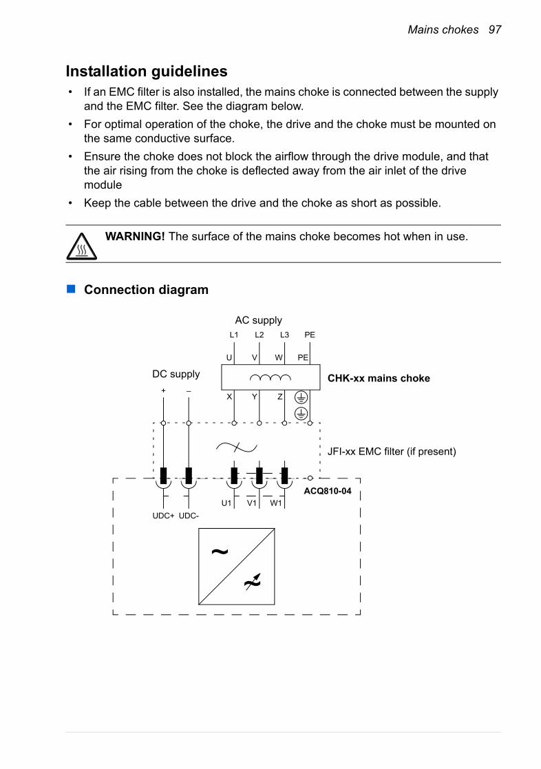
Mains chokes 97
Installation guidelines• If an EMC filter is also installed, the mains choke is connected between the supply
and the EMC filter. See the diagram below.• For optimal operation of the choke, the drive and the choke must be mounted on
the same conductive surface.• Ensure the choke does not block the airflow through the drive module, and that
the air rising from the choke is deflected away from the air inlet of the drive module
• Keep the cable between the drive and the choke as short as possible.
WARNING! The surface of the mains choke becomes hot when in use.
Connection diagram
~
AC supply
ACQ810-04
CHK-xx mains choke
JFI-xx EMC filter (if present)
~
L1 L2 L3 PE
DC supply
U1 V1 W1UDC+ UDC-
+ –
U V W PE
X Y Z

98 Mains chokes
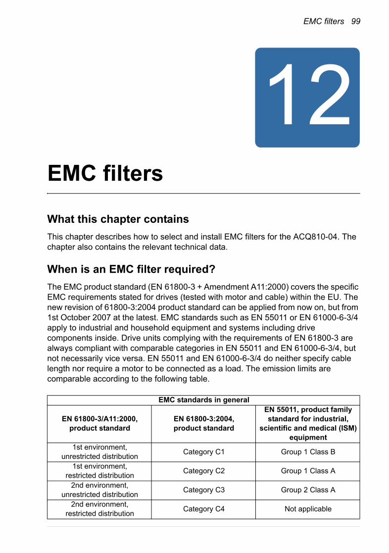
EMC filters 99
EMC filters
What this chapter containsThis chapter describes how to select and install EMC filters for the ACQ810-04. The chapter also contains the relevant technical data.
When is an EMC filter required?The EMC product standard (EN 61800-3 + Amendment A11:2000) covers the specific EMC requirements stated for drives (tested with motor and cable) within the EU. The new revision of 61800-3:2004 product standard can be applied from now on, but from 1st October 2007 at the latest. EMC standards such as EN 55011 or EN 61000-6-3/4 apply to industrial and household equipment and systems including drive components inside. Drive units complying with the requirements of EN 61800-3 are always compliant with comparable categories in EN 55011 and EN 61000-6-3/4, but not necessarily vice versa. EN 55011 and EN 61000-6-3/4 do neither specify cable length nor require a motor to be connected as a load. The emission limits are comparable according to the following table.
EMC standards in general
EN 61800-3/A11:2000, product standard
EN 61800-3:2004, product standard
EN 55011, product family standard for industrial,
scientific and medical (ISM) equipment
1st environment, unrestricted distribution Category C1 Group 1 Class B
1st environment, restricted distribution Category C2 Group 1 Class A
2nd environment, unrestricted distribution Category C3 Group 2 Class A
2nd environment, restricted distribution Category C4 Not applicable

100 EMC filters
Filter type JFI-A1 or JFI-B1 is required in order to meet the category C3 level with the ACQ810-04 drive installation, including a motor with a max. 100 m cable. This level corresponds to the A limits for Group 2 equipment according to EN 55011. The filter is delivered as standard. With frame sizes A and B, the filter is external; with frame sizes C and D, the filter is internal. If the drive is equipped with filtering option +0E200, it does not contain the filter.
An external EMC filter of the type JFI-0x is required in order to meet the category C2 level with the ACQ810-04 drive installation, including a motor with a max. 100 m cable. This level corresponds to the A limits for Group 1 equipment according to EN 55011. The filter is an optional device.
WARNING! An EMC filter must not be installed if the drive is connected to an IT power system (i.e. an ungrounded, or a high resistance grounded [over 30 ohm] power system).
Selection table
All EMC filters are protected to IP20. Refer to page 117 for dimensions of the JFI-x1 filters. Refer to page 119 for dimensions, wire sizes and tightening torques of the JFI-0x filters.
EMC filters for ACQ810-04
Drive typeACQ810-04…
Filter typeEN 61800-3:2004:
Category C3EN 61800-3:2004:
Category C2-02A7-4
external filter JFI-A1 external filter JFI-02-03A0-4-03A5-4-04A9-4-06A3-4-08A3-4
external filter JFI-B1 external filter JFI-03-11A0-4-14A4-4-021A-4
internal filter
external filter JFI-05-028A-4-035A-4-040A-4-053A-4
external filter JFI-07-067A-4-080A-4
00581898
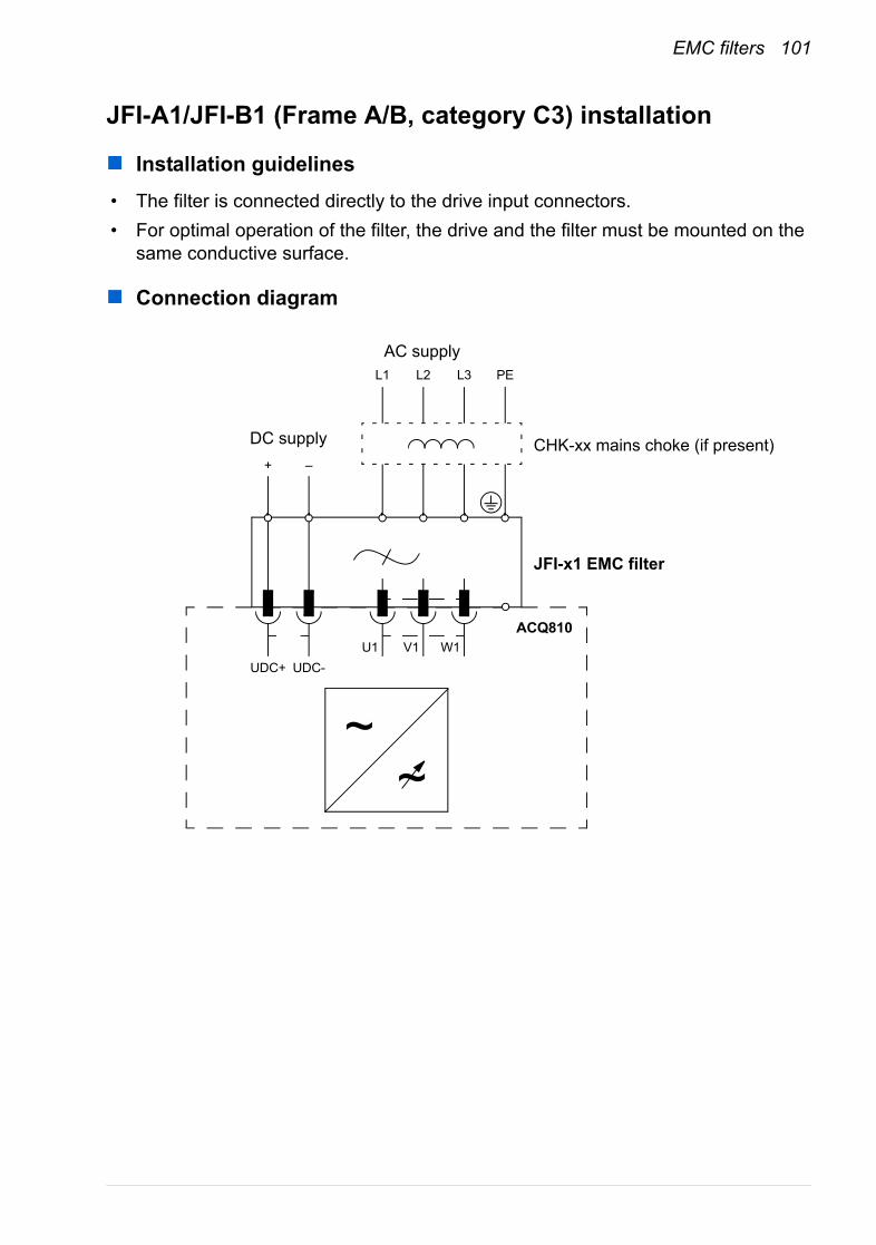
EMC filters 101
JFI-A1/JFI-B1 (Frame A/B, category C3) installation
Installation guidelines• The filter is connected directly to the drive input connectors.• For optimal operation of the filter, the drive and the filter must be mounted on the
same conductive surface.
Connection diagram
~
AC supply
ACQ810
CHK-xx mains choke (if present)
JFI-x1 EMC filter
~
L1 L2 L3 PE
DC supply
U1 V1 W1UDC+ UDC-
+ –
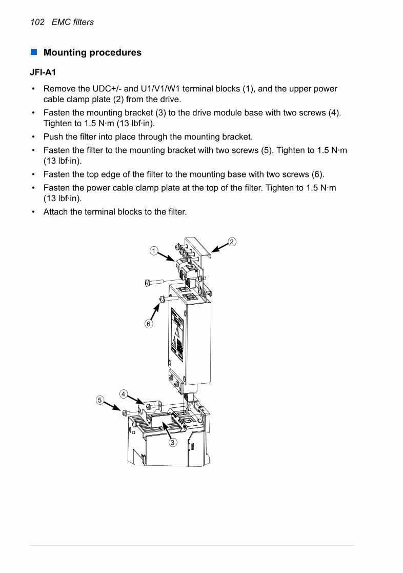
102 EMC filters
Mounting procedures
JFI-A1
• Remove the UDC+/- and U1/V1/W1 terminal blocks (1), and the upper power cable clamp plate (2) from the drive.
• Fasten the mounting bracket (3) to the drive module base with two screws (4). Tighten to 1.5 N·m (13 lbf·in).
• Push the filter into place through the mounting bracket.• Fasten the filter to the mounting bracket with two screws (5). Tighten to 1.5 N·m
(13 lbf·in).• Fasten the top edge of the filter to the mounting base with two screws (6).• Fasten the power cable clamp plate at the top of the filter. Tighten to 1.5 N·m
(13 lbf·in).• Attach the terminal blocks to the filter.
1
6
2
54
3
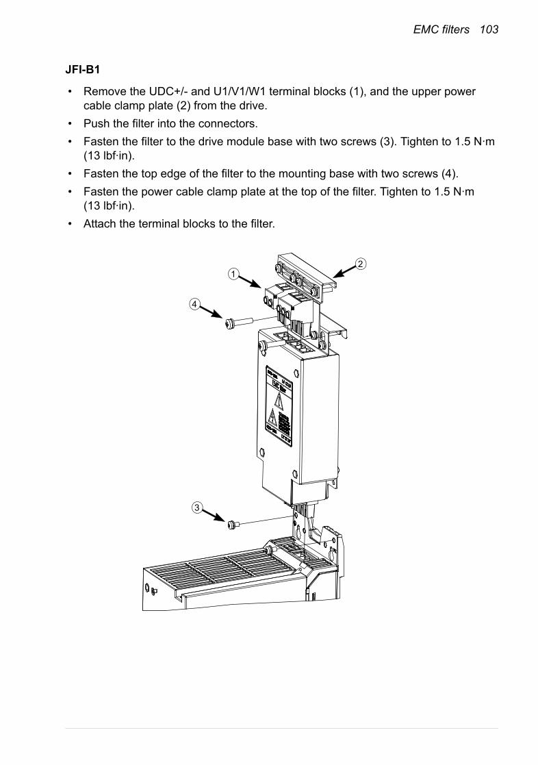
EMC filters 103
JFI-B1
• Remove the UDC+/- and U1/V1/W1 terminal blocks (1), and the upper power cable clamp plate (2) from the drive.
• Push the filter into the connectors.• Fasten the filter to the drive module base with two screws (3). Tighten to 1.5 N·m
(13 lbf·in).• Fasten the top edge of the filter to the mounting base with two screws (4).• Fasten the power cable clamp plate at the top of the filter. Tighten to 1.5 N·m
(13 lbf·in).• Attach the terminal blocks to the filter.
12
3
4
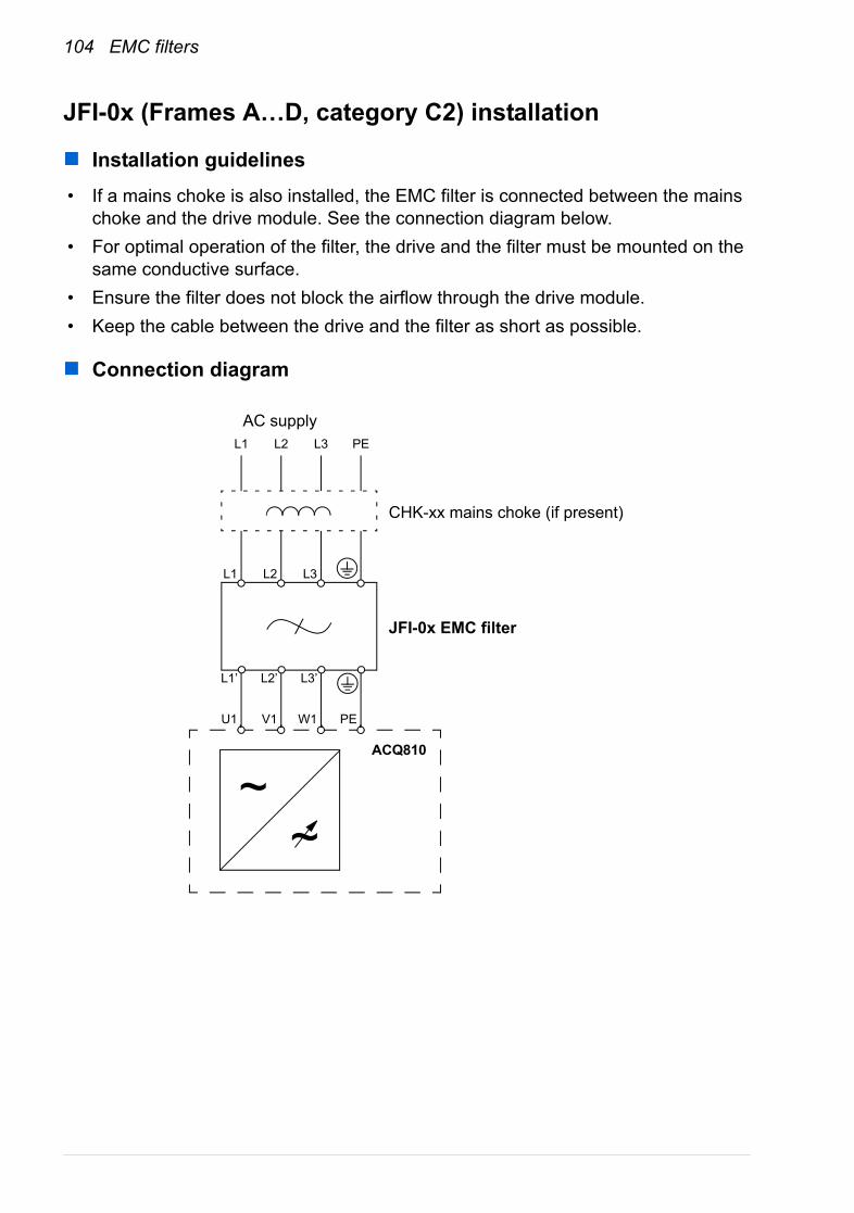
104 EMC filters
JFI-0x (Frames A…D, category C2) installation
Installation guidelines• If a mains choke is also installed, the EMC filter is connected between the mains
choke and the drive module. See the connection diagram below.• For optimal operation of the filter, the drive and the filter must be mounted on the
same conductive surface.• Ensure the filter does not block the airflow through the drive module.• Keep the cable between the drive and the filter as short as possible.
Connection diagram
~
AC supply
ACQ810
CHK-xx mains choke (if present)
JFI-0x EMC filter
~
L1 L2 L3
L1’ L2’
U1 V1 W1
PE
PE
L3’
L1 L2 L3
du/dt and common mode filtering 105
du/dt and common mode filtering
What this chapter containsThis chapter describes how to select du/dt and common mode filtering for the ACQ810-04. The chapter also contains the relevant technical data.
When is du/dt or common mode filtering required?The output of the drive comprises – regardless of output frequency – pulses of approximately 1.35 times the equivalent supply voltage with a very short rise time. This is the case with all drives employing modern IGBT inverter technology.
The voltage of the pulses can be almost double at the motor terminals, depending on the attenuation and reflection properties of the motor cable and the terminals. This in turn can cause additional stress on the motor and motor cable insulation.
Modern variable speed drives with their fast-rising voltage pulses and high switching frequencies can generate current pulses that flow through the motor bearings, which can gradually erode the bearing races and rolling elements.
The stress on motor insulation can be avoided by using optional ABB du/dt filters. du/dt filters also reduce bearing currents. Common mode filtering mainly reduces bearing currents.
To avoid damage to the motor bearings, the cables must be selected and installed according to the instructions given in chapter Electrical installation. In addition, du/dt filtering, common mode filtering, and insulated N-end bearings must be used according to the following table.
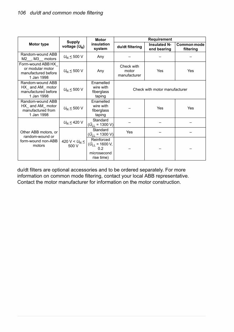
106 du/dt and common mode filtering
du/dt filters are optional accessories and to be ordered separately. For more information on common mode filtering, contact your local ABB representative. Contact the motor manufacturer for information on the motor construction.
Motor type Supply voltage (UN)
Motor insulation
system
Requirement
du/dt filtering Insulated N-end bearing
Common mode filtering
Random-wound ABB M2__, M3__ motors UN < 500 V Any – – –
Form-wound ABB HX_ or modular motor
manufactured before 1 Jan 1998
UN < 500 V AnyCheck with
motor manufacturer
Yes Yes
Random-wound ABB HX_ and AM_ motor manufactured before
1 Jan 1998
UN < 500 V
Enamelled wire with fiberglass
taping
Check with motor manufacturer
Random-wound ABB HX_ and AM_ motor manufactured from
1 Jan 1998
UN < 500 V
Enamelled wire with fiberglass
taping
– Yes Yes
Other ABB motors, or random-wound or
form-wound non-ABB motors
UN < 420 V Standard(ÛLL = 1300 V) – – –
420 V < UN < 500 V
Standard(ÛLL = 1300 V) Yes – –
Reinforced(ÛLL = 1600 V,
0.2 microsecond
rise time)
– – –
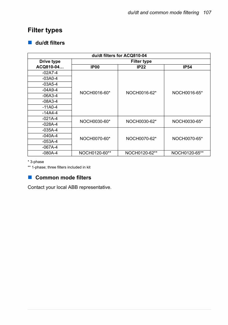
du/dt and common mode filtering 107
Filter types
du/dt filters
* 3-phase** 1-phase; three filters included in kit
Common mode filters
Contact your local ABB representative.
du/dt filters for ACQ810-04Drive type
ACQ810-04…Filter type
IP00 IP22 IP54-02A7-4
NOCH0016-60* NOCH0016-62* NOCH0016-65*
-03A0-4-03A5-4-04A9-4-06A3-4-08A3-4-11A0-4-14A4-4-021A-4 NOCH0030-60* NOCH0030-62* NOCH0030-65*-028A-4-035A-4
NOCH0070-60* NOCH0070-62* NOCH0070-65*-040A-4-053A-4-067A-4-080A-4 NOCH0120-60** NOCH0120-62** NOCH0120-65**

108 du/dt and common mode filtering
Technical data
du/dt filters
Dimensions and weights
* Dimensions given are per phase
Degree of protection
IP00, IP22 and IP54
Common mode filtersContact your local ABB representative.
InstallationFollow the instructions included with the filters.
Filter typeHeight
mm (inches)Width
mm (inches)Depth
mm (inches)Weightkg (lbs)
NOCH0016-60 195 (7.68) 140 (5.51) 115 (4.53) 2.4 (5.3)NOCH0030-60 215 (8.46) 165 (6.50) 130 (5.12) 4.7 (10.4)NOCH0070-60 261 (10.28) 180 (7.09) 150 (5.91) 9.5 (20.9)NOCH0120-60* 106 (4.17) 154 (6.06) 200 (7.87) 7.0 (15.4)NOCH0016-62 323 (12.72) 199 (7.83) 154 (6.06) 6 (13.2)NOCH0030-62 348 (13.70) 249 (9.80) 172 (6.77) 9 (19.8)NOCH0070-62 433 (17.05) 279 (10.98) 202 (7.95) 15.5 (34.17)NOCH0120-62* 765 (30.12) 308 (12.13) 256 (10.07) 45 (99)NOCH0016-65 323 (12.72) 199 (7.83) 154 (6.06) 6 (13.2)NOCH0030-65 348 (13.70) 249 (9.80) 172 (6.77) 9 (19.8)NOCH0070-65 433 (17.05) 279 (10.98) 202 (7.95) 15.5 (34.17)NOCH0120-65* 765 (30.12) 308 (12.13) 256 (10.07) 45 (99)

Dimension drawings 109
Dimension drawings
What this chapter containsDimension drawings of the ACQ810-04 and related accessories are shown below. The dimensions are given in millimeters and [inches].
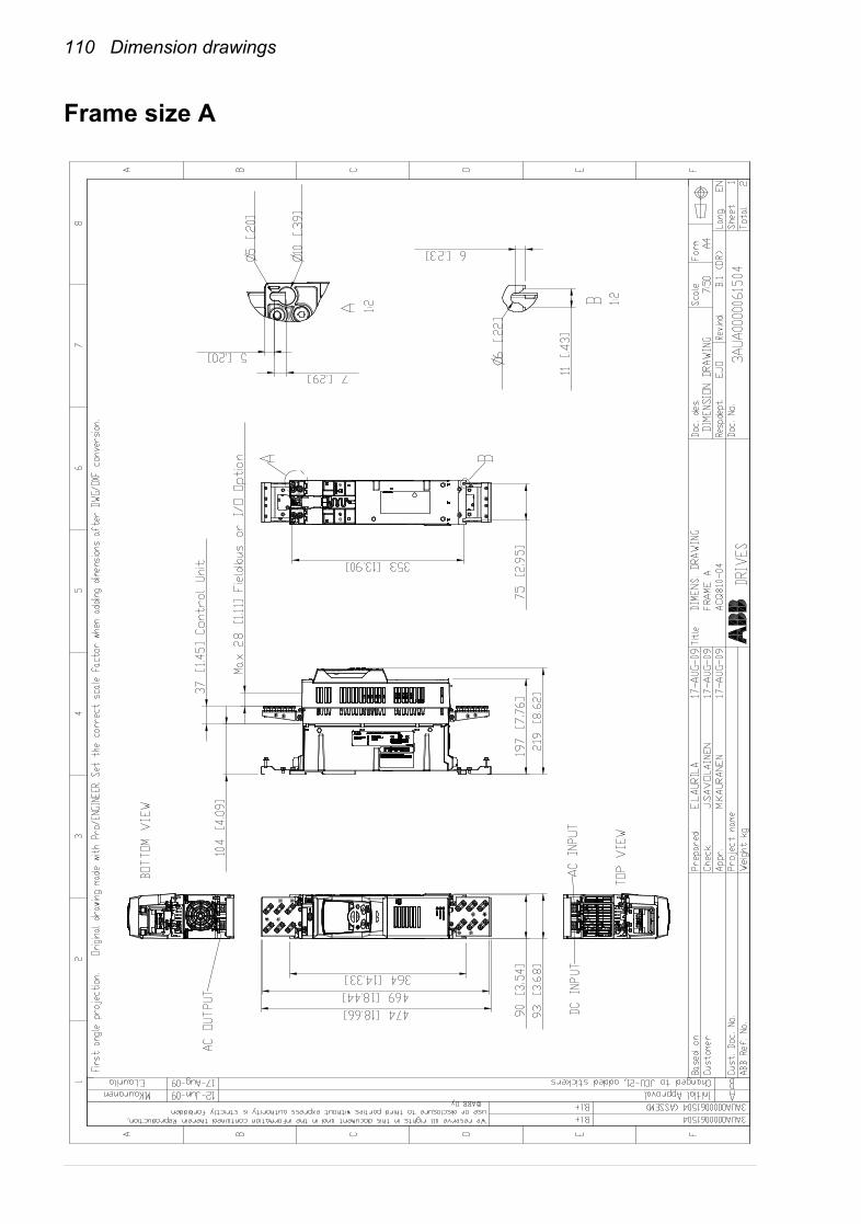
110 Dimension drawings
Frame size A

Dimension drawings 111

112 Dimension drawings
Frame size B
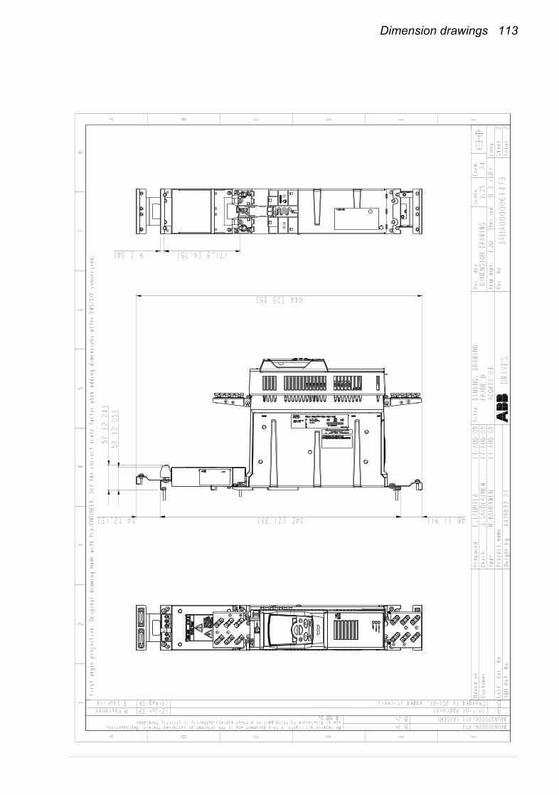
Dimension drawings 113
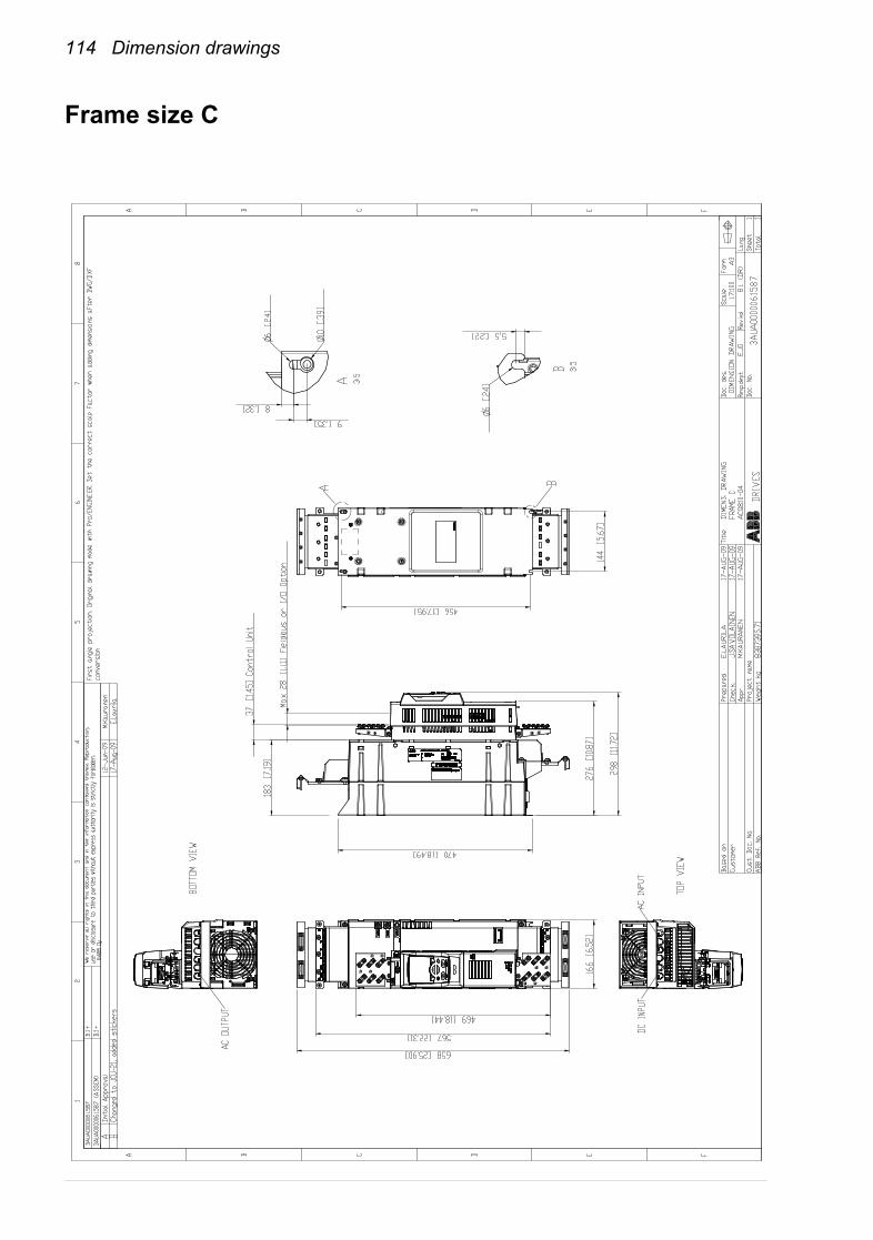
114 Dimension drawings
Frame size C
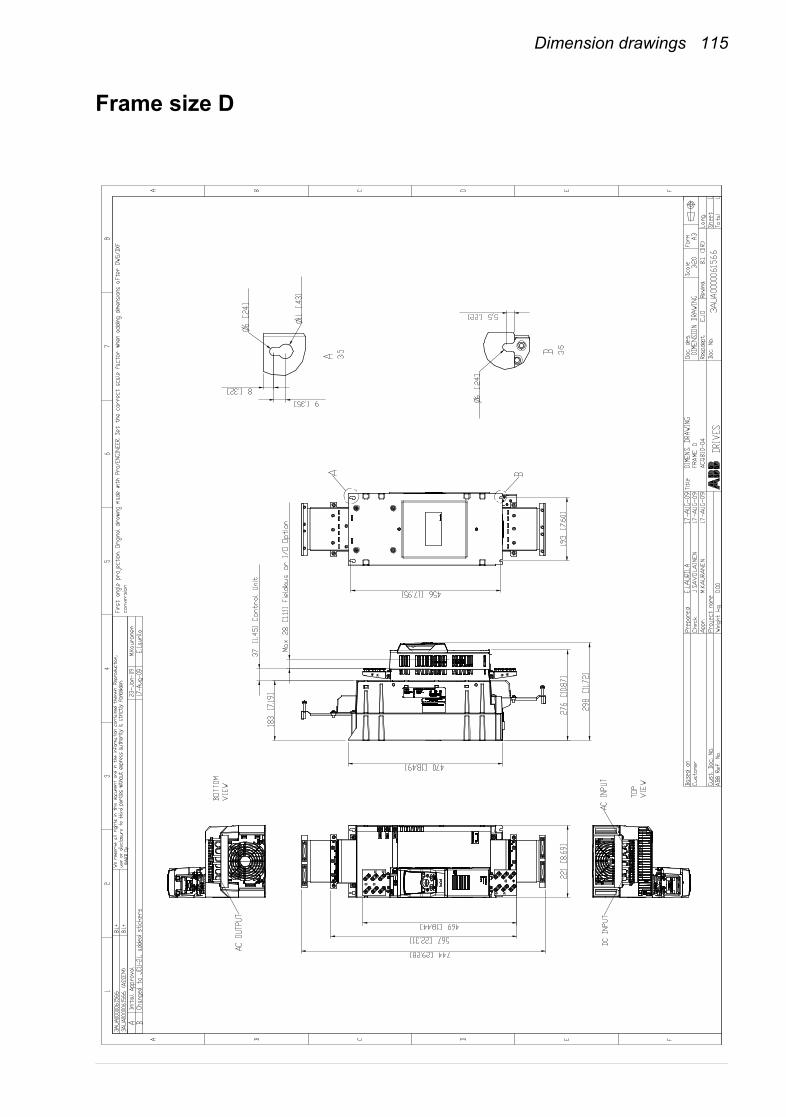
Dimension drawings 115
Frame size D
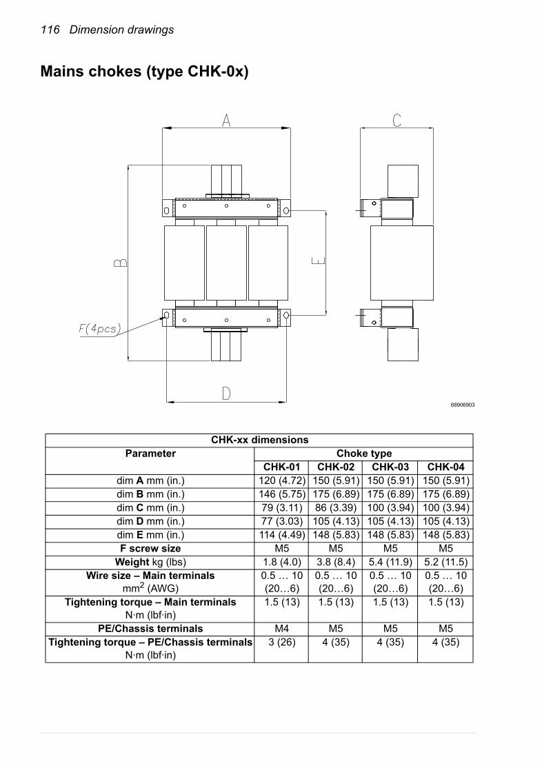
116 Dimension drawings
Mains chokes (type CHK-0x)
CHK-xx dimensionsParameter Choke type
CHK-01 CHK-02 CHK-03 CHK-04dim A mm (in.) 120 (4.72) 150 (5.91) 150 (5.91) 150 (5.91)dim B mm (in.) 146 (5.75) 175 (6.89) 175 (6.89) 175 (6.89)dim C mm (in.) 79 (3.11) 86 (3.39) 100 (3.94) 100 (3.94)dim D mm (in.) 77 (3.03) 105 (4.13) 105 (4.13) 105 (4.13)dim E mm (in.) 114 (4.49) 148 (5.83) 148 (5.83) 148 (5.83)F screw size M5 M5 M5 M5
Weight kg (lbs) 1.8 (4.0) 3.8 (8.4) 5.4 (11.9) 5.2 (11.5)Wire size – Main terminals
mm2 (AWG)0.5 … 10 (20…6)
0.5 … 10 (20…6)
0.5 … 10 (20…6)
0.5 … 10 (20…6)
Tightening torque – Main terminalsN·m (lbf·in)
1.5 (13) 1.5 (13) 1.5 (13) 1.5 (13)
PE/Chassis terminals M4 M5 M5 M5Tightening torque – PE/Chassis terminals
N·m (lbf·in)3 (26) 4 (35) 4 (35) 4 (35)
68906903
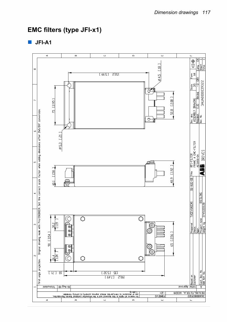
Dimension drawings 117
EMC filters (type JFI-x1)
JFI-A1
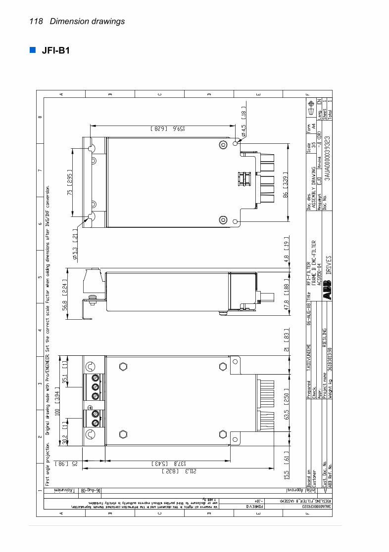
118 Dimension drawings
JFI-B1
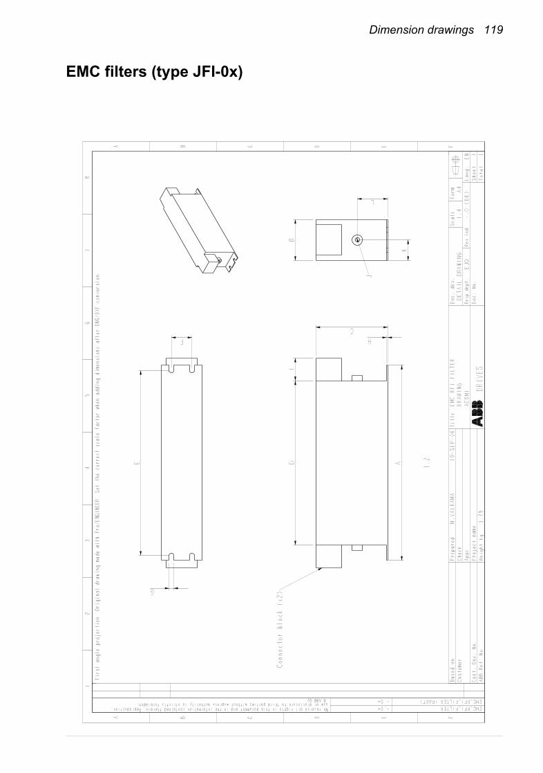
Dimension drawings 119
EMC filters (type JFI-0x)

120 Dimension drawings
JFI-x
x di
men
sion
s
Para
met
erFi
lter t
ype
JFI-0
2JF
I-03
JFI-0
5JF
I-07
Dim
. A m
m (i
n.)
250
(9.8
4)25
0 (9
.84)
250
(9.8
4)27
0 (1
0.63
)D
im. B
mm
(in.
)45
(1.7
7)50
(1.9
7)85
(3.3
5)90
(3.5
4)D
im. C
mm
(in.
)70
(2.7
6)85
(3.3
5)90
(3.5
4)15
0 (5
.91)
Dim
. D m
m (i
n.)
220
(8.6
6)24
0 (9
.45)
220
(8.6
6)24
0 (9
.45)
Dim
. E m
m (i
n.)
235
(9.2
5)25
5 (1
0.04
)23
5 (9
.25)
255
(10.
04)
Dim
. F m
m (i
n.)
25 (0
.98)
30 (1
.18)
60 (2
.36)
65 (2
.56)
Dim
. G m
m (i
n.)
5.4
(0.2
1)5.
4 (0
.21)
5.4
(0.2
1)6.
5 (0
.26)
Dim
. H m
m (i
n.)
1 (0
.04)
1 (0
.04)
1 (0
.04)
1.5
(0.0
6)D
im. I
mm
(in.
)22
(0.8
7)25
(0.9
8)39
(1.5
4)45
(1.7
7)D
im. J
M5
M5
M6
M10
Dim
. K m
m (i
n.)
22.5
(0.8
9)25
(0.9
8)42
.5 (1
.67)
45 (1
.77)
Dim
. L m
m (i
n.)
29.5
(1.1
6)39
.5 (1
.56)
26.5
(1.0
4)64
(2.5
2)W
eigh
t kg
(lbs)
0.8
(1.7
5)1.
1 (2
.4)
1.8
(4.0
)3.
9 (8
.5)
Wire
siz
e (s
olid
)m
m2
(AW
G)
0.2
…10
(AW
G24
…8)
0.5
…16
(AW
G20
…6)
6…35
(AW
G8…
2)16
…50
(AW
G4…
1/0)
Wire
siz
e (s
tran
ded)
mm
2 (AW
G)
0.2
…6
(AW
G24
…10
)0.
5…
10(A
WG
20…
8)10
…25
(AW
G6…
4)16
…50
(AW
G4…
1/0)
Tigh
teni
ng to
rque
of
term
inal
s N
·m (l
bf·in
)1.
5…
1.8
(13.
3…
15.9
)1.
5…
1.8
(13.
3…
15.9
)4.
0…
4.5
(35
…40
)7…
8(6
0…70
)

Further information
Product and service inquiriesAddress any inquiries about the product to your local ABB representative, quoting the type designation and serial number of the unit in question. A listing of ABB sales, support and service contacts can be found by navigating to www.abb.com/drives and selecting Sales, Support and Service network.
Product trainingFor information on ABB product training, navigate to www.abb.com/drives and select Training courses.
Providing feedback on ABB Drives manualsYour comments on our manuals are welcome. Go to www.abb.com/drives and select Document Library – Manuals feedback form (LV AC drives).
Document library on the InternetYou can find manuals and other product documents in PDF format on the Internet. Go to www.abb.com/drives and select Document Library. You can browse the library or enter selection criteria, for example a document code, in the search field.

3AU
A00
0005
5160
Rev
A /
ENE
FFE
CTI
VE
: 200
9-09
-18
ABB OyAC DrivesP.O. Box 184FI-00381 HELSINKIFINLANDTelephone +358 10 22 11Fax +358 10 22 22681Internet www.abb.com/drives
ABB Inc.Automation Technologies Drives & Motors16250 West Glendale DriveNew Berlin, WI 53151 USATelephone 262 785-3200
800-HELP-365Fax 262 780-5135
ABB Beijing Drive Systems Co. Ltd.No. 1, Block D, A-10 Jiuxianqiao BeiluChaoyang DistrictBeijing, P.R. China, 100015Telephone +86 10 5821 7788Fax +86 10 5821 7618Internet www.abb.com