Embed Size (px)
Citation preview

PROJECT DESIGN DOCUMENT FORM (CDM PDD) - Version 03.1. CDM – Executive Board page 1
CLEAN DEVELOPMENT MECHANISM PROJECT DESIGN DOCUMENT FORM (CDM-PDD)
Version 03 - in effect as of: 28 July 2006
CONTENTS A. General description of project activity B. Application of a baseline and monitoring methodology C. Duration of the project activity / crediting period D. Environmental impacts E. Stakeholders’ comments
Annexes Annex 1: Contact information on participants in the project activity Annex 2: Information regarding public funding Annex 3: Baseline information
Annex 4: Monitoring plan
PROJECT DESIGN DOCUMENT FORM (CDM PDD) - Version 03.1. CDM – Executive Board page 2 SECTION A. General description of project activity A.1 Title of the project activity: >> Xuzhou Landfill Gas Utilisation Project A.2. Description of the project activity: >> Xuzhou landfill has just opened and is designed to receive 1100 tonnes of municipal solid waste per day from 2006, and is currently receiving between 800 and 850 tonnes per day. Under the project activity, landfill gas extraction equipment will be installed and operated and the extracted gas will be used to generate electricity. When the yield of gas is insufficient to power a generator, an enclosed flare will be employed to minimise vented methane. Alternatively the gas may also be used to fuel a leachate evaporation unit (LEU) which will be installed on site as part of the project activity to promote air and ground water quality. The leachate which removed from the bottom of the landfill which is produced as by products from biological degradation of waste or from rainfall which has percolated through the cover. The LEU will reduce leachate up to 97% leaving a non- hazardous residue which will be recirculated to the landfill or solidified for landfill disposal. The project activity will bring a number of benefits to the project owners and city of Xuzhou: Environmental impacts: Improved air quality, in particular reduction of odours commonly associated with landfill; reduced leachate, reducing the burden on local sewerage systems; global benefits through reduced impact upon climate change. Social impacts: The improved air quality will result in improved quality of life for neighbours of the landfill; the utilisation of a renewable source of energy to generate electricity will contribute to China’s sustainable development. Economic impacts: The landfill operators will benefit from an additional source of revenue, helping to secure their future and the continued provision of sanitary waste disposal; employment opportunities will be created through the construction, operation and continuous monitoring of the project activity. Technology transfer: The project will introduce new technology to the landfill management sector in China, demonstrating how improved gas capture techniques can enhance the yield of methane and result in more power generation. A.3. Project participants: >>
Name of Party Involved (*) ((host) indicates a host Party)
Private and/or public entity(ies) project participants (as applicable)
Indicate if the Party involved wishes to be considered as project participant (Yes/No)

PROJECT DESIGN DOCUMENT FORM (CDM PDD) - Version 03.1. CDM – Executive Board page 3
People’s Republic of China (host) Xuzhou Yanchun landfill No
United Kingdom of Great Britain and Northern
Ireland
Sindicatum Carbon Capital Ltd No
(*) In accordance with the CDM modalities and procedures, at the time of making the CDM-PDD public at the stage of validation, a Party involved may or may not have provided its approval. At the time of requesting registration, the approval by the Party(ies) involved is required.
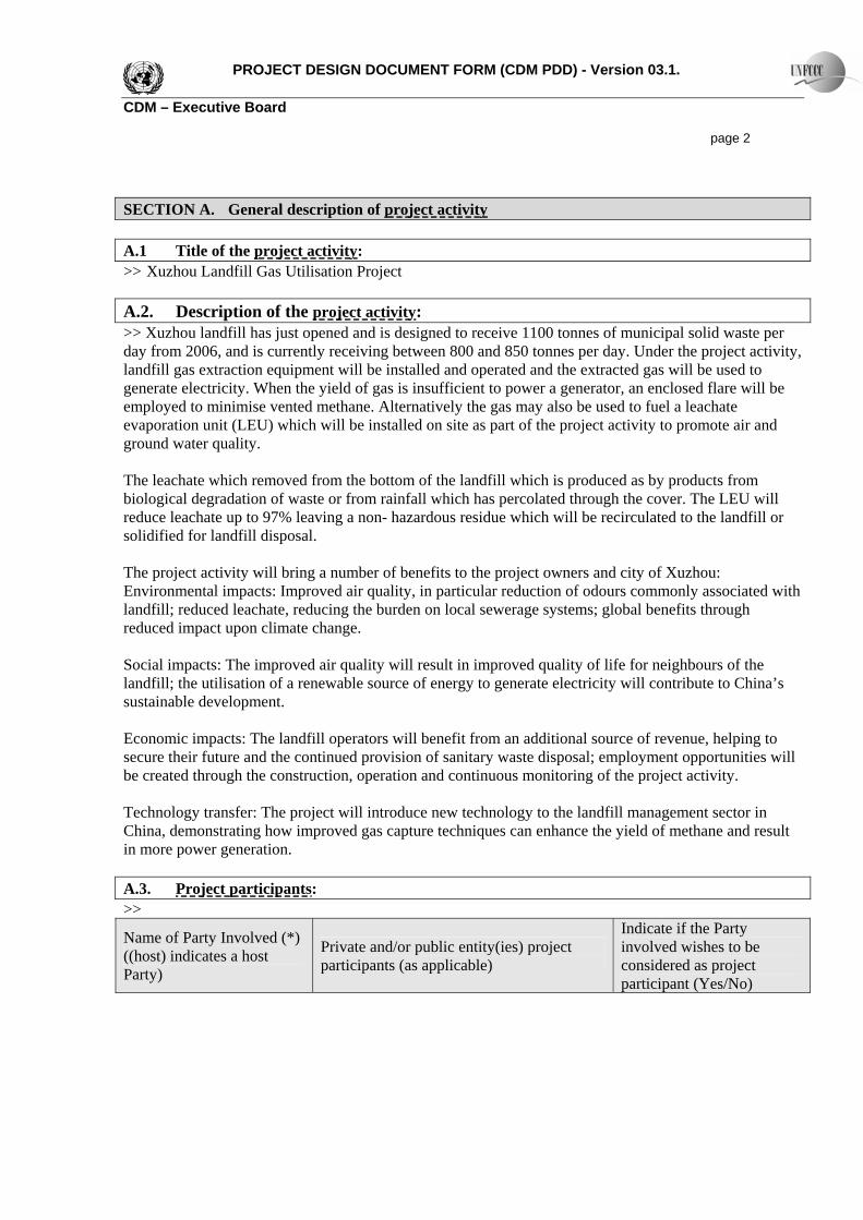
A.4. Technical description of the project activity: A.4.1. Location of the project activity: >> XuZhou landfill is located in the west of the city, 22 km from XuZhou’s city centre. A.4.1.1. Host Party(ies): >> People’s Republic of China A.4.1.2. Region/State/Province etc.: >> Jiangsu A.4.1.3. City/Town/Community etc: >> Dapeng Town, Tongshan County, Xuzhou City A.4.1.4. Detail of physical location, including information allowing the unique identification of this project activity (maximum one page): >>
PROJECT DESIGN DOCUMENT FORM (CDM PDD) - Version 03.1. CDM – Executive Board page 4
Figure 1: Plan of Xuzhou Landfill
Leachate treatment facility
Leachate tank
Phase 1
Access ramp
Phase 2
A.4.2. Category(ies) of project activity: >> Sectoral Category 13 – Waste Handling and Disposal and Sectoral Category 1 – Energy industries (renewable - / non-renewable sources) A.4.3. Technology to be employed by the project activity: >> The project activity will use state of the art horizontal piping systems combined with rainfall management techniques including drainage and erosion control and daily cover, to maximise land gas extraction efficiency. High density plastic horizontal pipes will be laid into the already existing waste, surrounded in gravel and connected to a pump, which will be used to create differential pressures within the landfill. The landfill gas, comprising approximately 50% methane will be extracted from the landfill and piped to the generator(s) / flares. Enhanced control over extraction of the landfill gas will be achieved by installing horizontal pipes with perforations over only a portion of the length of the pipe. Rainfall ingression will be minimised by:
a) landscaping to minimise and flow of rainwater into the landfill from the surrounding landscape b) application of a proprietary daily cover material that is relatively (though not completely)
impermeable c) where possible, ensuring that incoming waste is as dry as possible (for example, covering waste
piles and during transport in the wet season etc. Flooding of horizontal pipes will be minimised by:
PROJECT DESIGN DOCUMENT FORM (CDM PDD) - Version 03.1. CDM – Executive Board page 5
d) sloping them downwards towards the exit of the landfill (so that condensates flow down the pipe rather than gather in the pipe)
e) minimising rainfall ingression (see above) f) removing leachate through a leachate drainage system g) evaporation of the leachate by using an LEU powered by landfill gas h) installing successive levels of pipes so that if lower pipes are flooded, pipes higher up the profile
can be utilised. The gas will be extracted, treated (to clean and dry it) and then burnt in suitable generators. When there is sufficient gas, it will be routed to the generator. As the gas yield increases as the land fill receives more waste, it is anticipated that successive generators will be added. Between each new addition, the gas will used were possible in the LEU or if quantities are lower than needed a flare will destroy the excess gas. The usage and monitoring of the evaporation unit which contains an internal flare will be calculated as other conventional flares.
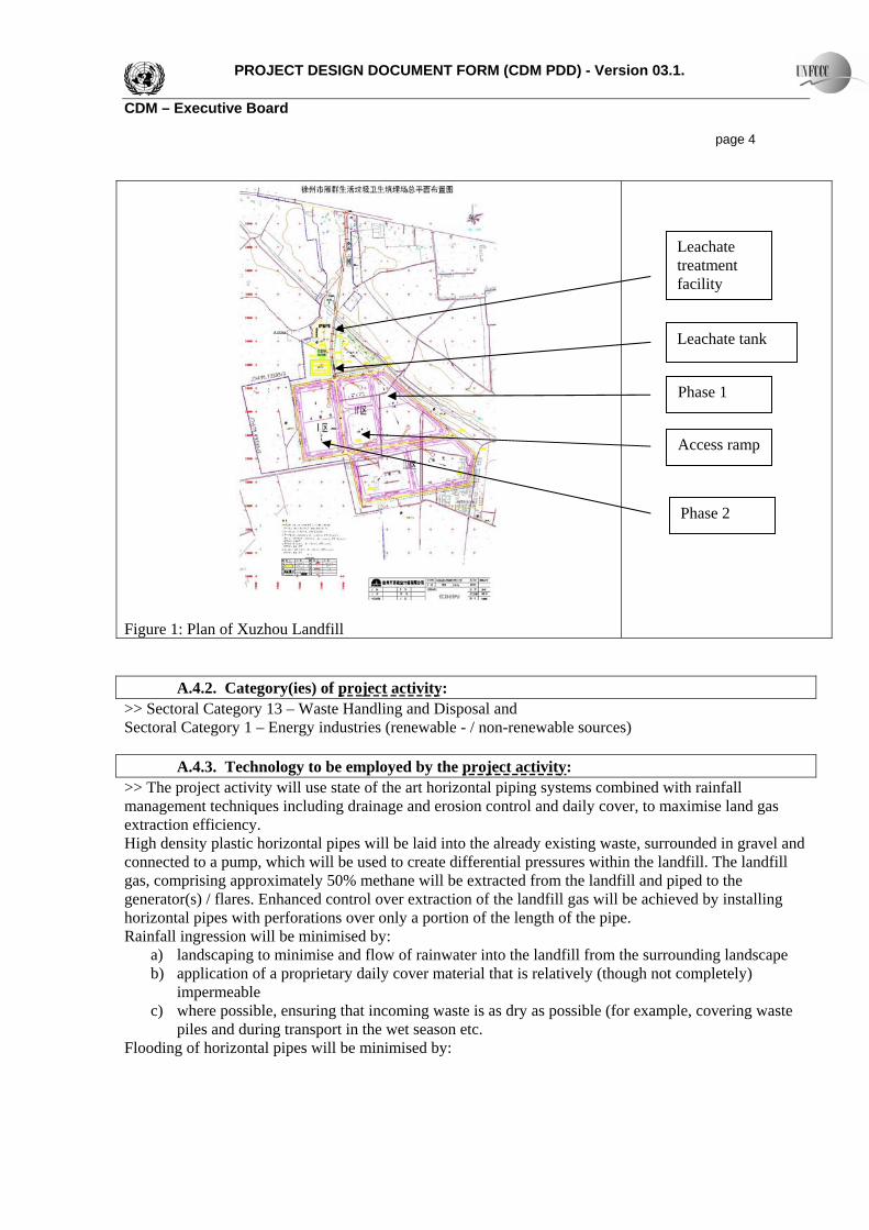
Fig 2: Shows the empty landfill ready for utilized. On the basis vertical passive vents, white geomembrane and flat soil adequate for horizontal pipes.
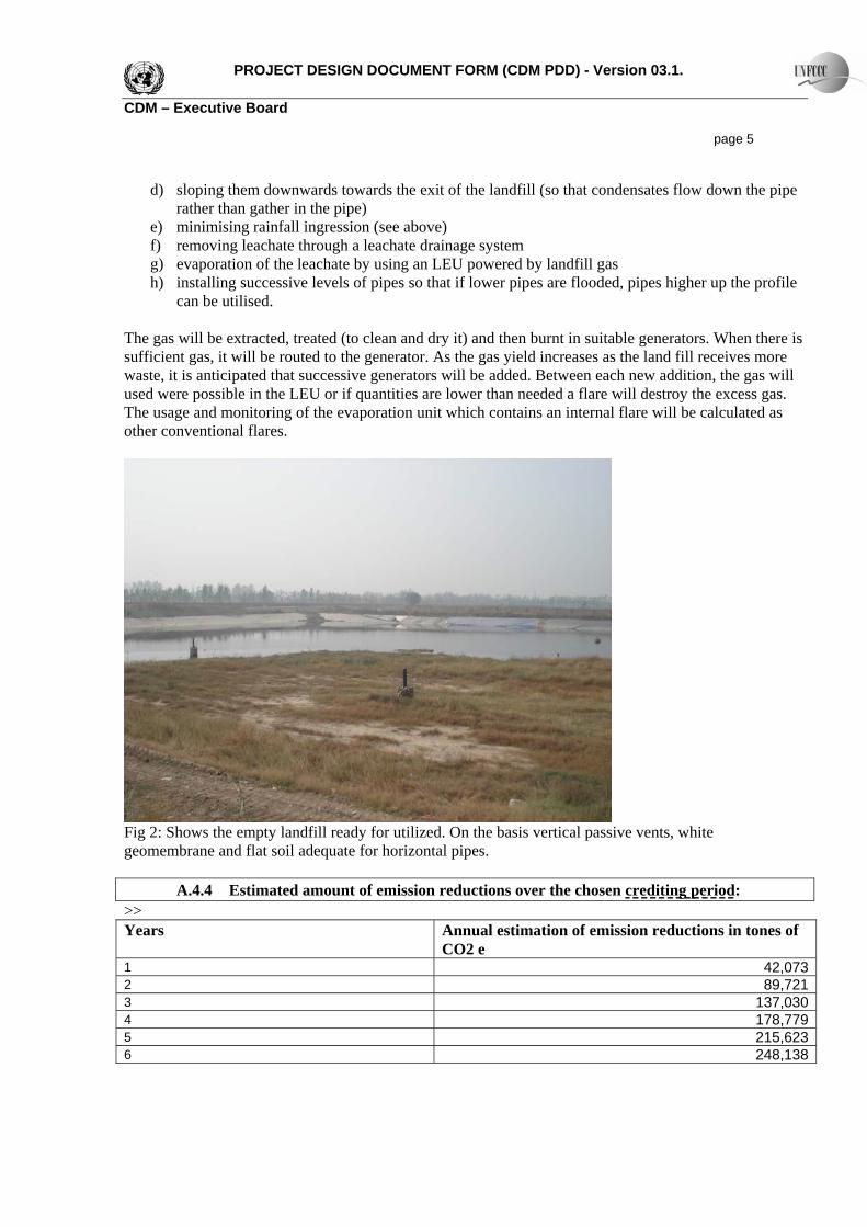
A.4.4 Estimated amount of emission reductions over the chosen crediting period: >> Years Annual estimation of emission reductions in tones of
CO2 e 1 42,0732 89,7213 137,0304 178,7795 215,6236 248,138
PROJECT DESIGN DOCUMENT FORM (CDM PDD) - Version 03.1. CDM – Executive Board page 6 7 276,8328 302,1549 324,50110 344,222Total Estimated reduction (tonnes CO2e) 2,159,075Total number of crediting years 10Annual average over the crediting period of estimated reductions (tonnes of CO2e)
215,908 A.4.5. Public funding of the project activity: >> The project activity will not be funded by any public money.
PROJECT DESIGN DOCUMENT FORM (CDM PDD) - Version 03.1. CDM – Executive Board page 7 SECTION B. Application of a baseline and monitoring methodology B.1. Title and reference of the approved baseline and monitoring methodology applied to the project activity: >>ACM0001 Version 4, Consolidated baseline methodology for landfill gas project activities. B.2 Justification of the choice of the methodology and why it is applicable to the project activity:
>> This methodology is applicable to landfill gas capture project activities, where the baseline scenario is the partial or total atmospheric release of the gas and the project activities include situations such as: a) The captured gas is flared; or b) The captured gas is used to produce energy (e.g. electricity/thermal energy), but no emission reductions are claimed for displacing or avoiding energy from other sources’; or c) The captured gas is used to produce energy (e.g. electricity/thermal energy), and emission reductions are claimed for displacing or avoiding energy generation from other sources. In this case a baseline methodology for electricity and/or thermal energy displaced shall be provided or an approved one used, including the ACM0002 “Consolidated Methodology for Grid-Connected Power Generation from Renewable”. If capacity of electricity generated is less than 15MW, and/or thermal energy displaced is less than 54 TJ (15GWh), small-scale methodologies can be used.
The application of this methodology is justified on the grounds that, as will be shown below, the baseline is total atmospheric release of the gas and the project activity includes both power generation and some flaring. As the project power output is less than 15MW, the small scale methodology will be applied / in the later stages of the project may exceed 15MW, ACM0002 will be applied. The small scale methodology to be used is Type I. D- Renewable electricity generation for a grid.
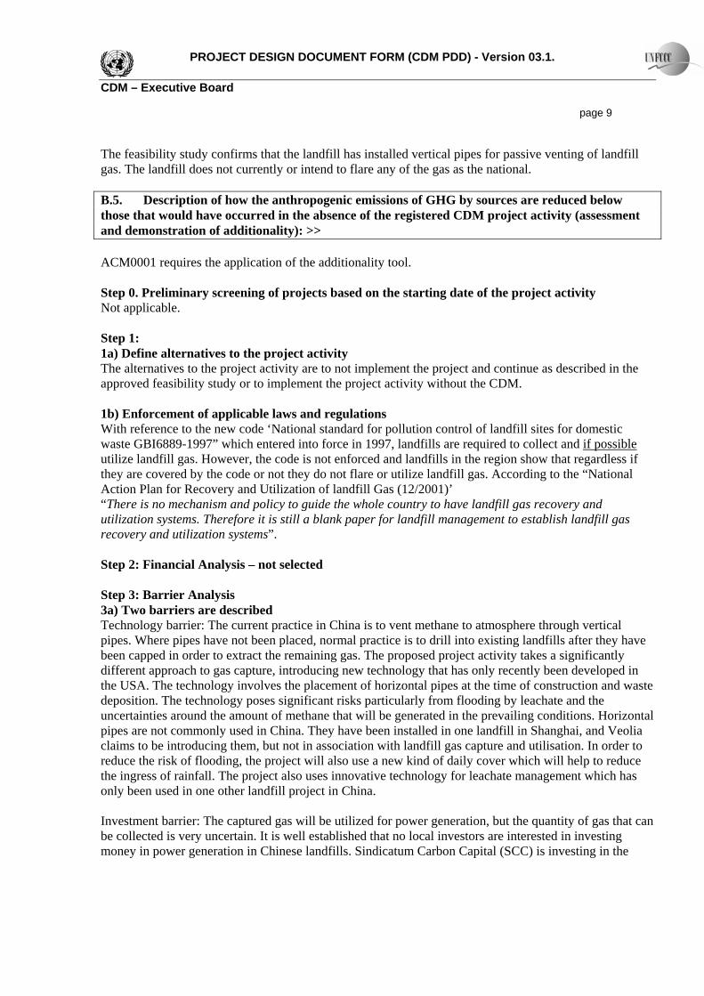
B.3. Description of the sources and gases included in the project boundary >> Baseline Source Gas Justification / Explanation Emissions of methane as a result of venting
CH4 Included ・ Main emission source.
CO2 Excluded CH4 Excluded
Emissions from destruction of methane in the baseline
N2O Excluded
・ There is no methane destruction in the baseline
Grid electricity generation (electricity provided to the grid)
CO2 Included ・ Only CO2 emissions associated with the power generated by the project activity are included.
・ Use of combined margin method as described in ACM0002 should be used / Small scale meth
CH4 Excluded ・ Excluded for simplification. This is conservative.
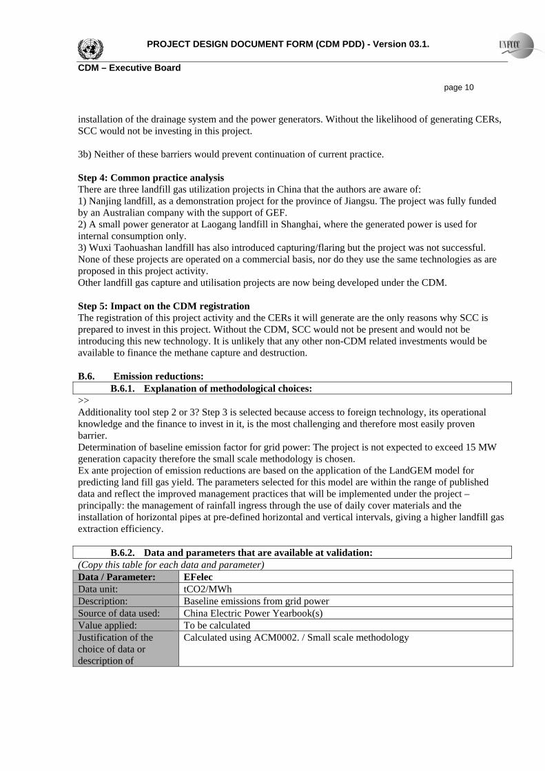
PROJECT DESIGN DOCUMENT FORM (CDM PDD) - Version 03.1. CDM – Executive Board page 8 N2O Excluded ・ Excluded for simplification. This is conservative.
Project activity Source Gas Justification / Explanation Emissions of methane as a result of continued venting
CH4 Excluded ・ No methane emissions are expected under the project activity, but in the event that the flare or generators are not operating, this might arise. Only the change in LFG emissions release will be taken into account, by monitoring the methane used or destroyed by the project activity.
CO2 Included ・ The project will use energy for pumping. This may be taken from the grid, in which case the emissions will be added to the project emissions, or the power may come directly from the generators on site, in which case electricity exported to the grid will be reduced.
CH4 Excluded ・ Excluded for simplification. This emission source is assumed to be very small.
On-site fuel consumption due to the project activity, including transport of the gas
N2O Excluded ・ Excluded for simplification. This emission source is assumed to be very small.
Emissions from methane destruction
CO2 Included ・ From the combustion of methane, but as the methane is organic in origin, emissions equal zero.
Fugitive emissions of unburned methane
CH4 Included ・ Small amounts of methane will remain unburned. Default emission factor of 0.5% is applied to power generation and the default of 10% or the test results will be applied to flares, if utilized.
Fugitive methane emissions from on-site equipment
CH4 Excluded ・ Excluded for simplification. This emission source is assumed to be very small.
Fugitive methane emissions from gas supply pipeline or in relation to use in vehicles
CH4 Excluded ・ Excluded for simplification.
Accidental methane release
CH4 Excluded ・ Excluded for simplification. This emission source is assumed to be very small.
B.4. Description of how the baseline scenario is identified and description of the identified baseline scenario: >> The baseline scenario is identified by reference to the approved feasibility study (which describes the landfill will be designed and managed) and the existing regulations and guidelines. A copy of the feasibility study is attached/ available to the DOE / summary in English / Chinese.
PROJECT DESIGN DOCUMENT FORM (CDM PDD) - Version 03.1. CDM – Executive Board page 9 The feasibility study confirms that the landfill has installed vertical pipes for passive venting of landfill gas. The landfill does not currently or intend to flare any of the gas as the national. B.5. Description of how the anthropogenic emissions of GHG by sources are reduced below those that would have occurred in the absence of the registered CDM project activity (assessment and demonstration of additionality): >> ACM0001 requires the application of the additionality tool. Step 0. Preliminary screening of projects based on the starting date of the project activity Not applicable. Step 1: 1a) Define alternatives to the project activity The alternatives to the project activity are to not implement the project and continue as described in the approved feasibility study or to implement the project activity without the CDM. 1b) Enforcement of applicable laws and regulations With reference to the new code ‘National standard for pollution control of landfill sites for domestic waste GBI6889-1997” which entered into force in 1997, landfills are required to collect and if possible utilize landfill gas. However, the code is not enforced and landfills in the region show that regardless if they are covered by the code or not they do not flare or utilize landfill gas. According to the “National Action Plan for Recovery and Utilization of landfill Gas (12/2001)’ “There is no mechanism and policy to guide the whole country to have landfill gas recovery and utilization systems. Therefore it is still a blank paper for landfill management to establish landfill gas recovery and utilization systems”. Step 2: Financial Analysis – not selected Step 3: Barrier Analysis 3a) Two barriers are described Technology barrier: The current practice in China is to vent methane to atmosphere through vertical pipes. Where pipes have not been placed, normal practice is to drill into existing landfills after they have been capped in order to extract the remaining gas. The proposed project activity takes a significantly different approach to gas capture, introducing new technology that has only recently been developed in the USA. The technology involves the placement of horizontal pipes at the time of construction and waste deposition. The technology poses significant risks particularly from flooding by leachate and the uncertainties around the amount of methane that will be generated in the prevailing conditions. Horizontal pipes are not commonly used in China. They have been installed in one landfill in Shanghai, and Veolia claims to be introducing them, but not in association with landfill gas capture and utilisation. In order to reduce the risk of flooding, the project will also use a new kind of daily cover which will help to reduce the ingress of rainfall. The project also uses innovative technology for leachate management which has only been used in one other landfill project in China. Investment barrier: The captured gas will be utilized for power generation, but the quantity of gas that can be collected is very uncertain. It is well established that no local investors are interested in investing money in power generation in Chinese landfills. Sindicatum Carbon Capital (SCC) is investing in the
PROJECT DESIGN DOCUMENT FORM (CDM PDD) - Version 03.1. CDM – Executive Board page 10 installation of the drainage system and the power generators. Without the likelihood of generating CERs, SCC would not be investing in this project. 3b) Neither of these barriers would prevent continuation of current practice. Step 4: Common practice analysis There are three landfill gas utilization projects in China that the authors are aware of: 1) Nanjing landfill, as a demonstration project for the province of Jiangsu. The project was fully funded by an Australian company with the support of GEF. 2) A small power generator at Laogang landfill in Shanghai, where the generated power is used for internal consumption only. 3) Wuxi Taohuashan landfill has also introduced capturing/flaring but the project was not successful. None of these projects are operated on a commercial basis, nor do they use the same technologies as are proposed in this project activity. Other landfill gas capture and utilisation projects are now being developed under the CDM. Step 5: Impact on the CDM registration The registration of this project activity and the CERs it will generate are the only reasons why SCC is prepared to invest in this project. Without the CDM, SCC would not be present and would not be introducing this new technology. It is unlikely that any other non-CDM related investments would be available to finance the methane capture and destruction. B.6. Emission reductions:
B.6.1. Explanation of methodological choices: >> Additionality tool step 2 or 3? Step 3 is selected because access to foreign technology, its operational knowledge and the finance to invest in it, is the most challenging and therefore most easily proven barrier. Determination of baseline emission factor for grid power: The project is not expected to exceed 15 MW generation capacity therefore the small scale methodology is chosen. Ex ante projection of emission reductions are based on the application of the LandGEM model for predicting land fill gas yield. The parameters selected for this model are within the range of published data and reflect the improved management practices that will be implemented under the project – principally: the management of rainfall ingress through the use of daily cover materials and the installation of horizontal pipes at pre-defined horizontal and vertical intervals, giving a higher landfill gas extraction efficiency.
B.6.2. Data and parameters that are available at validation: (Copy this table for each data and parameter) Data / Parameter: EFelec Data unit: tCO2/MWh Description: Baseline emissions from grid power Source of data used: China Electric Power Yearbook(s) Value applied: To be calculated Justification of the choice of data or description of
Calculated using ACM0002. / Small scale methodology
PROJECT DESIGN DOCUMENT FORM (CDM PDD) - Version 03.1. CDM – Executive Board page 11 measurement methods and procedures actually applied : Any comment:
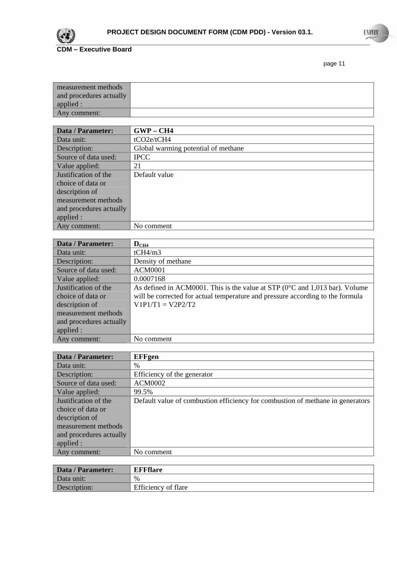
Data / Parameter: GWP – CH4 Data unit: tCO2e/tCH4 Description: Global warming potential of methane Source of data used: IPCC Value applied: 21 Justification of the choice of data or description of measurement methods and procedures actually applied :
Default value
Any comment: No comment Data / Parameter: DCH4
Data unit: tCH4/m3 Description: Density of methane Source of data used: ACM0001 Value applied: 0.0007168 Justification of the choice of data or description of measurement methods and procedures actually applied :
As defined in ACM0001. This is the value at STP (0°C and 1,013 bar). Volume will be corrected for actual temperature and pressure according to the formula V1P1/T1 = V2P2/T2
Any comment: No comment
Data / Parameter: EFFgen Data unit: % Description: Efficiency of the generator Source of data used: ACM0002 Value applied: 99.5% Justification of the choice of data or description of measurement methods and procedures actually applied :
Default value of combustion efficiency for combustion of methane in generators
Any comment: No comment
Data / Parameter: EFFflare Data unit: % Description: Efficiency of flare
PROJECT DESIGN DOCUMENT FORM (CDM PDD) - Version 03.1. CDM – Executive Board page 12 Source of data used: ACM0002 Value applied: 99% Justification of the choice of data or description of measurement methods and procedures actually applied :
90% is the default efficiency factor for enclosed flares. If tests are not performed annually on the flare, then the default factor will be applied. Otherwise tests are to be performed prior to the start of the crediting period and annually thereafter
Any comment: No comment Data / Parameter: EFFle Data unit: % Description: Efficiency of leachate evaporator Source of data used: ACM0002 Value applied: 90% Justification of the choice of data or description of measurement methods and procedures actually applied :
90% is the conservative default efficiency factor for leachate evaporators. Applications of the units show that efficiency rate can be up to 97%.If tests are not performed annually on the unit, then the default factor will be applied. Otherwise tests are to be performed prior to the start of the crediting period and annually thereafter.
Any comment: No comment
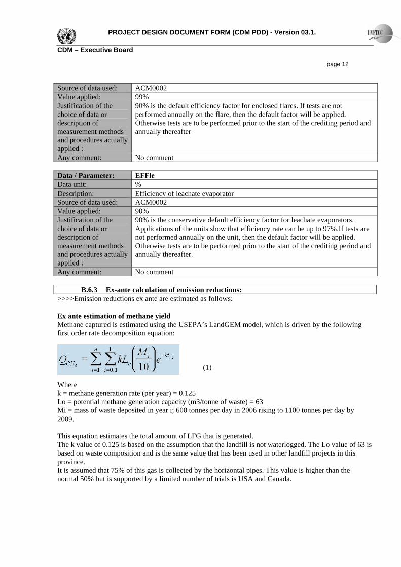
B.6.3 Ex-ante calculation of emission reductions: >>>>Emission reductions ex ante are estimated as follows: Ex ante estimation of methane yield Methane captured is estimated using the USEPA’s LandGEM model, which is driven by the following first order rate decomposition equation:
(1)
Where k = methane generation rate (per year) = 0.125 Lo = potential methane generation capacity (m3/tonne of waste) = 63 Mi = mass of waste deposited in year i; 600 tonnes per day in 2006 rising to 1100 tonnes per day by 2009. This equation estimates the total amount of LFG that is generated. The k value of 0.125 is based on the assumption that the landfill is not waterlogged. The Lo value of 63 is based on waste composition and is the same value that has been used in other landfill projects in this province. It is assumed that 75% of this gas is collected by the horizontal pipes. This value is higher than the normal 50% but is supported by a limited number of trials is USA and Canada.
PROJECT DESIGN DOCUMENT FORM (CDM PDD) - Version 03.1. CDM – Executive Board page 13
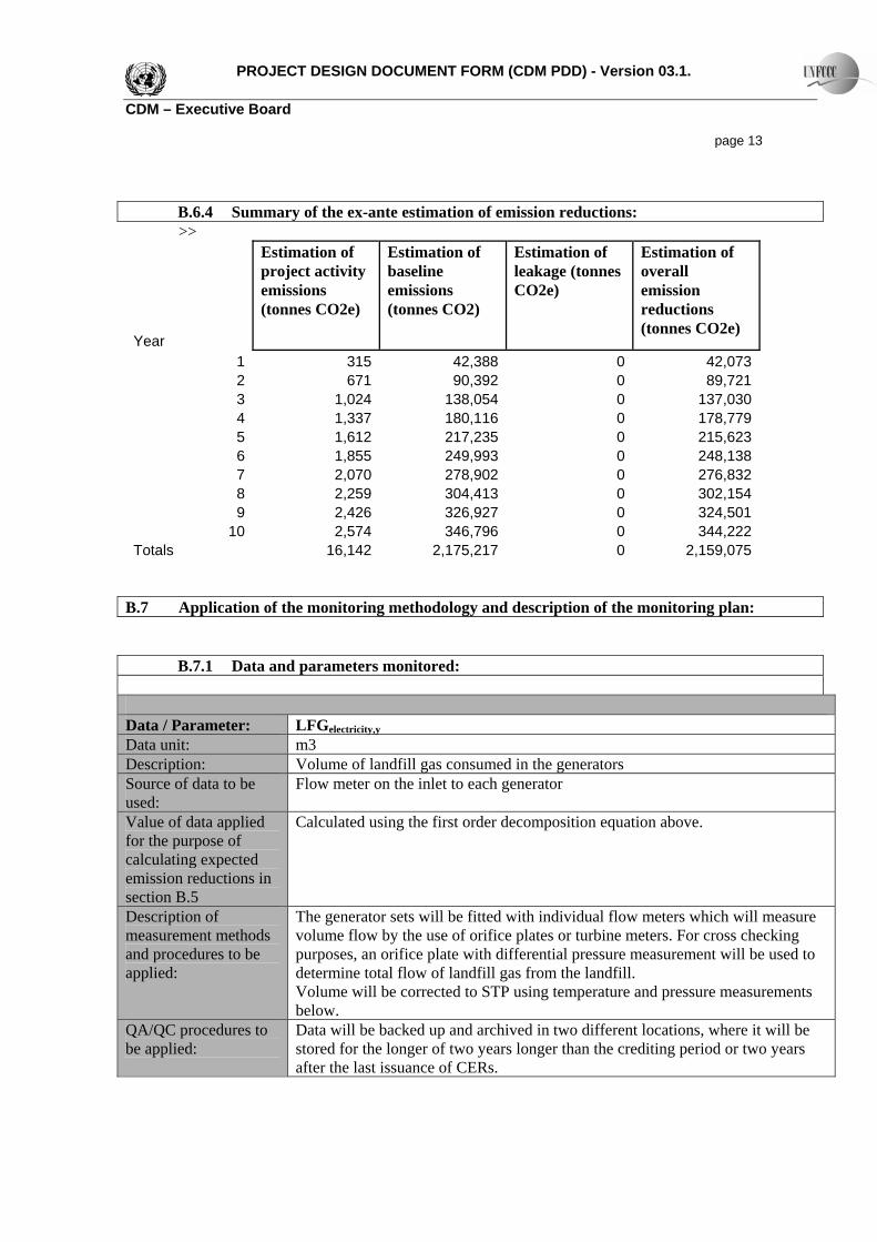
B.6.4 Summary of the ex-ante estimation of emission reductions: >>
Year
Estimation of project activity emissions (tonnes CO2e)
Estimation of baseline emissions (tonnes CO2)
Estimation of leakage (tonnes CO2e)
Estimation of overall emission reductions (tonnes CO2e)
1 315 42,388 0 42,0732 671 90,392 0 89,7213 1,024 138,054 0 137,0304 1,337 180,116 0 178,7795 1,612 217,235 0 215,6236 1,855 249,993 0 248,1387 2,070 278,902 0 276,8328 2,259 304,413 0 302,1549 2,426 326,927 0 324,501
10 2,574 346,796 0 344,222Totals 16,142 2,175,217 0 2,159,075
B.7 Application of the monitoring methodology and description of the monitoring plan:
B.7.1 Data and parameters monitored:
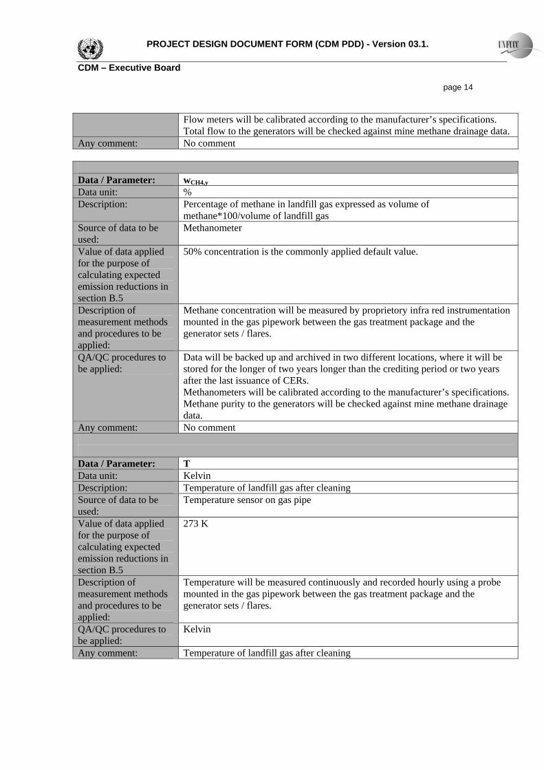
Data / Parameter: LFGelectricity,y Data unit: m3 Description: Volume of landfill gas consumed in the generators Source of data to be used:
Flow meter on the inlet to each generator
Value of data applied for the purpose of calculating expected emission reductions in section B.5
Calculated using the first order decomposition equation above.
Description of measurement methods and procedures to be applied:
The generator sets will be fitted with individual flow meters which will measure volume flow by the use of orifice plates or turbine meters. For cross checking purposes, an orifice plate with differential pressure measurement will be used to determine total flow of landfill gas from the landfill. Volume will be corrected to STP using temperature and pressure measurements below.
QA/QC procedures to be applied:
Data will be backed up and archived in two different locations, where it will be stored for the longer of two years longer than the crediting period or two years after the last issuance of CERs.
PROJECT DESIGN DOCUMENT FORM (CDM PDD) - Version 03.1. CDM – Executive Board page 14
Flow meters will be calibrated according to the manufacturer’s specifications. Total flow to the generators will be checked against mine methane drainage data.
Any comment: No comment
Data / Parameter: wCH4,y Data unit: % Description: Percentage of methane in landfill gas expressed as volume of
methane*100/volume of landfill gas Source of data to be used:
Methanometer
Value of data applied for the purpose of calculating expected emission reductions in section B.5
50% concentration is the commonly applied default value.
Description of measurement methods and procedures to be applied:
Methane concentration will be measured by proprietory infra red instrumentation mounted in the gas pipework between the gas treatment package and the generator sets / flares.
QA/QC procedures to be applied:
Data will be backed up and archived in two different locations, where it will be stored for the longer of two years longer than the crediting period or two years after the last issuance of CERs. Methanometers will be calibrated according to the manufacturer’s specifications. Methane purity to the generators will be checked against mine methane drainage data.
Any comment: No comment Data / Parameter: T Data unit: Kelvin Description: Temperature of landfill gas after cleaning Source of data to be used:
Temperature sensor on gas pipe
Value of data applied for the purpose of calculating expected emission reductions in section B.5
273 K
Description of measurement methods and procedures to be applied:
Temperature will be measured continuously and recorded hourly using a probe mounted in the gas pipework between the gas treatment package and the generator sets / flares.
QA/QC procedures to be applied:
Kelvin
Any comment: Temperature of landfill gas after cleaning
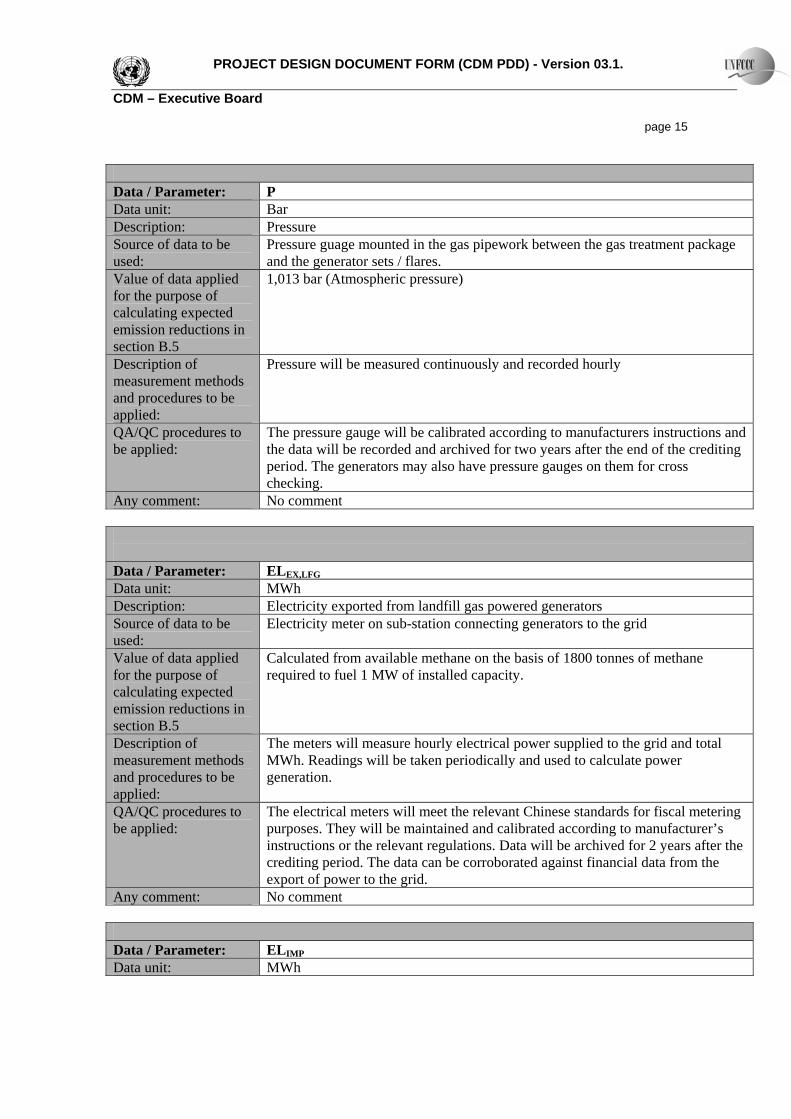
PROJECT DESIGN DOCUMENT FORM (CDM PDD) - Version 03.1. CDM – Executive Board page 15 Data / Parameter: P Data unit: Bar Description: Pressure Source of data to be used:
Pressure guage mounted in the gas pipework between the gas treatment package and the generator sets / flares.
Value of data applied for the purpose of calculating expected emission reductions in section B.5
1,013 bar (Atmospheric pressure)
Description of measurement methods and procedures to be applied:
Pressure will be measured continuously and recorded hourly
QA/QC procedures to be applied:
The pressure gauge will be calibrated according to manufacturers instructions and the data will be recorded and archived for two years after the end of the crediting period. The generators may also have pressure gauges on them for cross checking.
Any comment: No comment
Data / Parameter: ELEX,LFG
Data unit: MWh Description: Electricity exported from landfill gas powered generators Source of data to be used:
Electricity meter on sub-station connecting generators to the grid
Value of data applied for the purpose of calculating expected emission reductions in section B.5
Calculated from available methane on the basis of 1800 tonnes of methane required to fuel 1 MW of installed capacity.
Description of measurement methods and procedures to be applied:
The meters will measure hourly electrical power supplied to the grid and total MWh. Readings will be taken periodically and used to calculate power generation.
QA/QC procedures to be applied:
The electrical meters will meet the relevant Chinese standards for fiscal metering purposes. They will be maintained and calibrated according to manufacturer’s instructions or the relevant regulations. Data will be archived for 2 years after the crediting period. The data can be corroborated against financial data from the export of power to the grid.
Any comment: No comment Data / Parameter: ELIMP Data unit: MWh
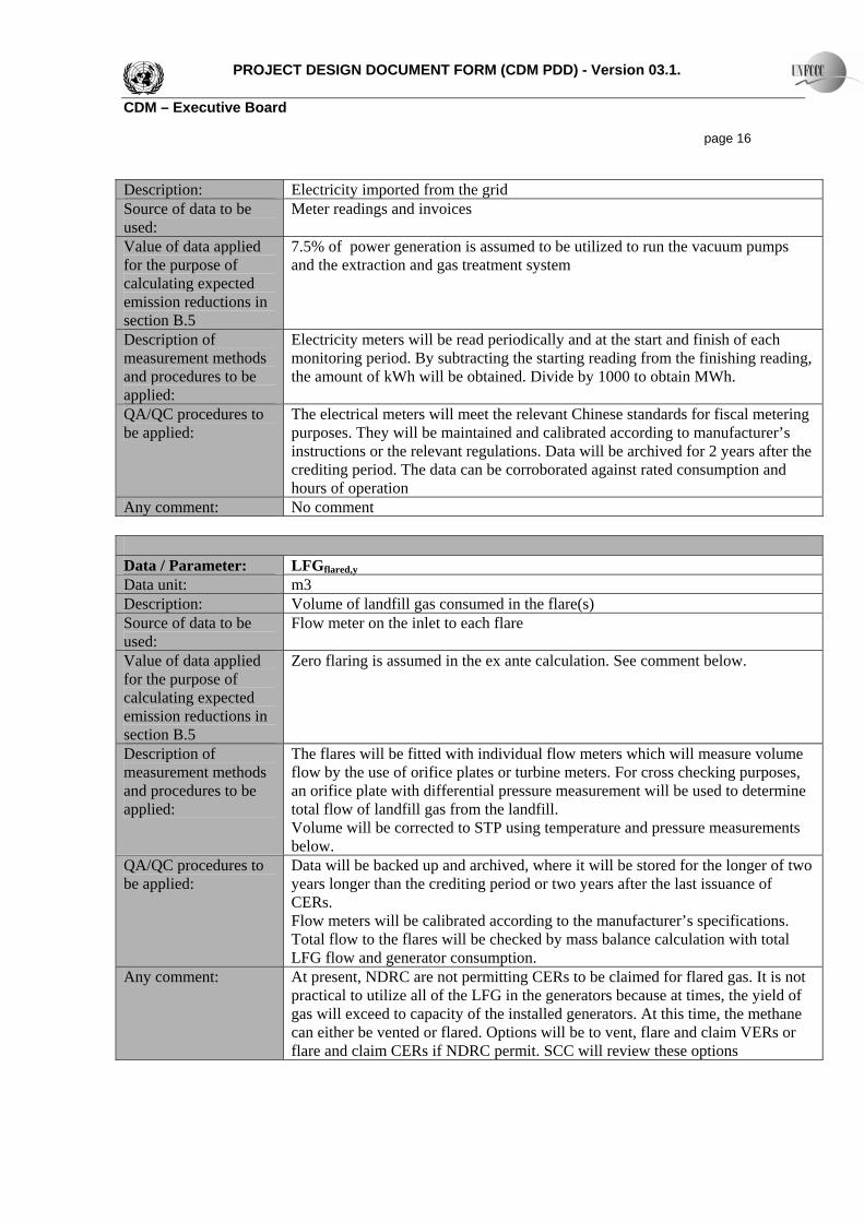
PROJECT DESIGN DOCUMENT FORM (CDM PDD) - Version 03.1. CDM – Executive Board page 16 Description: Electricity imported from the grid Source of data to be used:
Meter readings and invoices
Value of data applied for the purpose of calculating expected emission reductions in section B.5
7.5% of power generation is assumed to be utilized to run the vacuum pumps and the extraction and gas treatment system
Description of measurement methods and procedures to be applied:
Electricity meters will be read periodically and at the start and finish of each monitoring period. By subtracting the starting reading from the finishing reading, the amount of kWh will be obtained. Divide by 1000 to obtain MWh.
QA/QC procedures to be applied:
The electrical meters will meet the relevant Chinese standards for fiscal metering purposes. They will be maintained and calibrated according to manufacturer’s instructions or the relevant regulations. Data will be archived for 2 years after the crediting period. The data can be corroborated against rated consumption and hours of operation
Any comment: No comment
Data / Parameter: LFGflared,y
Data unit: m3 Description: Volume of landfill gas consumed in the flare(s) Source of data to be used:
Flow meter on the inlet to each flare
Value of data applied for the purpose of calculating expected emission reductions in section B.5
Zero flaring is assumed in the ex ante calculation. See comment below.
Description of measurement methods and procedures to be applied:
The flares will be fitted with individual flow meters which will measure volume flow by the use of orifice plates or turbine meters. For cross checking purposes, an orifice plate with differential pressure measurement will be used to determine total flow of landfill gas from the landfill. Volume will be corrected to STP using temperature and pressure measurements below.
QA/QC procedures to be applied:
Data will be backed up and archived, where it will be stored for the longer of two years longer than the crediting period or two years after the last issuance of CERs. Flow meters will be calibrated according to the manufacturer’s specifications. Total flow to the flares will be checked by mass balance calculation with total LFG flow and generator consumption.
Any comment: At present, NDRC are not permitting CERs to be claimed for flared gas. It is not practical to utilize all of the LFG in the generators because at times, the yield of gas will exceed to capacity of the installed generators. At this time, the methane can either be vented or flared. Options will be to vent, flare and claim VERs or flare and claim CERs if NDRC permit. SCC will review these options
PROJECT DESIGN DOCUMENT FORM (CDM PDD) - Version 03.1. CDM – Executive Board page 17
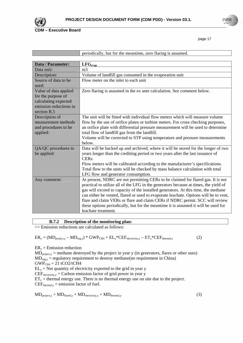
periodically, but for the meantime, zero flaring is assumed. Data / Parameter: LFGevap
Data unit: m3 Description: Volume of landfill gas consumed in the evaporation unit Source of data to be used:
Flow meter on the inlet to each unit
Value of data applied for the purpose of calculating expected emission reductions in section B.5
Zero flaring is assumed in the ex ante calculation. See comment below.
Description of measurement methods and procedures to be applied:
The unit will be fitted with individual flow meters which will measure volume flow by the use of orifice plates or turbine meters. For cross checking purposes, an orifice plate with differential pressure measurement will be used to determine total flow of landfill gas from the landfill. Volume will be corrected to STP using temperature and pressure measurements below.
QA/QC procedures to be applied:
Data will be backed up and archived, where it will be stored for the longer of two years longer than the crediting period or two years after the last issuance of CERs. Flow meters will be calibrated according to the manufacturer’s specifications. Total flow to the units will be checked by mass balance calculation with total LFG flow and generator consumption.
Any comment: At present, NDRC are not permitting CERs to be claimed for flared gas. It is not practical to utilize all of the LFG in the generators because at times, the yield of gas will exceed to capacity of the installed generators. At this time, the methane can either be vented, flared or used to evaporate leachate. Options will be to vent, flare and claim VERs or flare and claim CERs if NDRC permit. SCC will review these options periodically, but for the meantime it is assumed it will be used for leachate treatment.
B.7.2 Description of the monitoring plan:
>> Emission reductions are calculated as follows: ERy = (MDproject,y – MDreg,y) * GWPCH4 + ELy*CEFelectricity,y – ETy*CEFthermal,y (2)
ERy = Emission reduction MDproject,y = methane destroyed by the project in year y (in generators, flares or other uses) MDreg,y = regulatory requirement to destroy methane(no requirement in China) GWPCH4 = 21 tCO2/tCH4 ELy = Net quantity of electricity exported to the grid in year y CEFelectricity,y = Carbon emission factor of grid power in year y ETy = thermal energy use. There is no thermal energy use on site due to the project. CEFthermal,y = emission factor of fuel. MDproject,y = MDflared,y + MDelectricity,y + MDthermal,y (3)
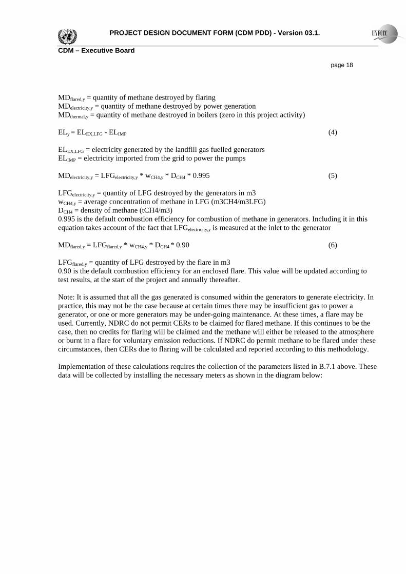
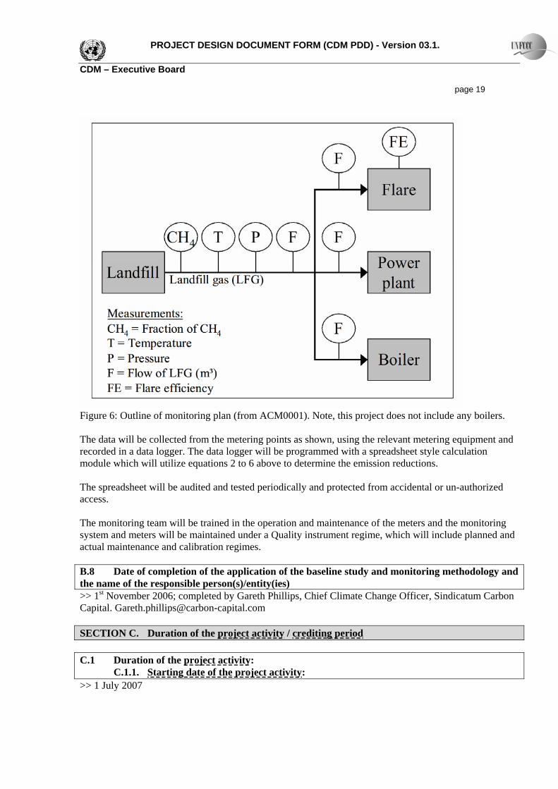
PROJECT DESIGN DOCUMENT FORM (CDM PDD) - Version 03.1. CDM – Executive Board page 18 MDflared,y = quantity of methane destroyed by flaring MDelectricity,y = quantity of methane destroyed by power generation MDthermal,y = quantity of methane destroyed in boilers (zero in this project activity) ELy = ELEX,LFG - ELIMP (4) ELEX,LFG = electricity generated by the landfill gas fuelled generators ELIMP = electricity imported from the grid to power the pumps MDelectricity,y = LFGelectricity,y * wCH4,y * DCH4 * 0.995 (5) LFGelectricity,y = quantity of LFG destroyed by the generators in m3 wCH4,y = average concentration of methane in LFG (m3CH4/m3LFG) DCH4 = density of methane (tCH4/m3) 0.995 is the default combustion efficiency for combustion of methane in generators. Including it in this equation takes account of the fact that LFGelectricity,y is measured at the inlet to the generator MDflared,y = LFGflared,y * wCH4,y * DCH4 * 0.90 (6) LFGflared,y = quantity of LFG destroyed by the flare in m3 0.90 is the default combustion efficiency for an enclosed flare. This value will be updated according to test results, at the start of the project and annually thereafter. Note: It is assumed that all the gas generated is consumed within the generators to generate electricity. In practice, this may not be the case because at certain times there may be insufficient gas to power a generator, or one or more generators may be under-going maintenance. At these times, a flare may be used. Currently, NDRC do not permit CERs to be claimed for flared methane. If this continues to be the case, then no credits for flaring will be claimed and the methane will either be released to the atmosphere or burnt in a flare for voluntary emission reductions. If NDRC do permit methane to be flared under these circumstances, then CERs due to flaring will be calculated and reported according to this methodology. Implementation of these calculations requires the collection of the parameters listed in B.7.1 above. These data will be collected by installing the necessary meters as shown in the diagram below:
PROJECT DESIGN DOCUMENT FORM (CDM PDD) - Version 03.1. CDM – Executive Board page 19
Figure 6: Outline of monitoring plan (from ACM0001). Note, this project does not include any boilers. The data will be collected from the metering points as shown, using the relevant metering equipment and recorded in a data logger. The data logger will be programmed with a spreadsheet style calculation module which will utilize equations 2 to 6 above to determine the emission reductions. The spreadsheet will be audited and tested periodically and protected from accidental or un-authorized access. The monitoring team will be trained in the operation and maintenance of the meters and the monitoring system and meters will be maintained under a Quality instrument regime, which will include planned and actual maintenance and calibration regimes. B.8 Date of completion of the application of the baseline study and monitoring methodology and the name of the responsible person(s)/entity(ies) >> 1st November 2006; completed by Gareth Phillips, Chief Climate Change Officer, Sindicatum Carbon Capital. [email protected] SECTION C. Duration of the project activity / crediting period C.1 Duration of the project activity: C.1.1. Starting date of the project activity: >> 1 July 2007
PROJECT DESIGN DOCUMENT FORM (CDM PDD) - Version 03.1. CDM – Executive Board page 20 C.1.2. Expected operational lifetime of the project activity: >> 25 Years C.2 Choice of the crediting period and related information: C.2.1. Renewable crediting period C.2.1.1. Starting date of the first crediting period: >> C.2.1.2. Length of the first crediting period: >> C.2.2. Fixed crediting period: C.2.2.1. Starting date: >> 1 July 2007 C.2.2.2. Length: >>10 Years SECTION D. Environmental impacts >> D.1. Documentation on the analysis of the environmental impacts, including transboundary impacts: >>The project activity is being implemented in a land fill that has already received approval from the relevant Chinese Authorities and is already receiving waste. The project will have many positive environmental impacts: It will reduce emissions of land fill gas and odours commonly associated with landfill sites The application of daily cover will improve the hygiene and of the site Improved rainfall management will result in less leachate and therefore less problems in treating the leachate Net generation of power from a renewable resource. Negative impacts include: A small amount of noise from generators – although this will be minimised by placing the generator sets in acoustically sealed containers Emissions of CO2 and very small amounts of NOx and SOx from the generators – the CO2 emissions have zero global warming impact, as they are derived from the combustion of methane from organic materials; emissions of SOx and NOx are well below the regulatory requirements Visual impacts – some pipework, the pumphouse and the generator sets will be visible, but in the context of the surrounding landscape the impact is not considered to be material.
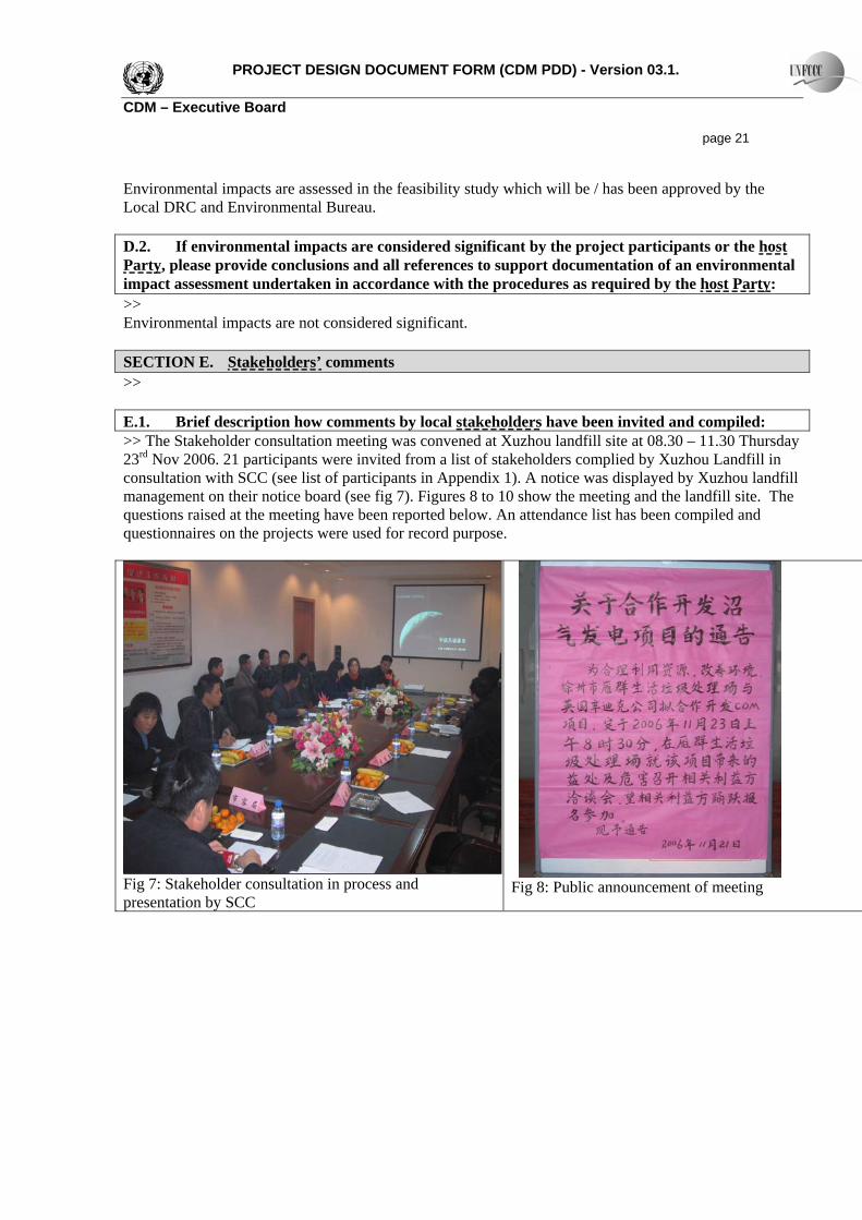
PROJECT DESIGN DOCUMENT FORM (CDM PDD) - Version 03.1. CDM – Executive Board page 21 Environmental impacts are assessed in the feasibility study which will be / has been approved by the Local DRC and Environmental Bureau. D.2. If environmental impacts are considered significant by the project participants or the host Party, please provide conclusions and all references to support documentation of an environmental impact assessment undertaken in accordance with the procedures as required by the host Party: >> Environmental impacts are not considered significant. SECTION E. Stakeholders’ comments >> E.1. Brief description how comments by local stakeholders have been invited and compiled: >> The Stakeholder consultation meeting was convened at Xuzhou landfill site at 08.30 – 11.30 Thursday 23rd Nov 2006. 21 participants were invited from a list of stakeholders complied by Xuzhou Landfill in consultation with SCC (see list of participants in Appendix 1). A notice was displayed by Xuzhou landfill management on their notice board (see fig 7). Figures 8 to 10 show the meeting and the landfill site. The questions raised at the meeting have been reported below. An attendance list has been compiled and questionnaires on the projects were used for record purpose.
Fig 7: Stakeholder consultation in process and presentation by SCC
Fig 8: Public announcement of meeting
PROJECT DESIGN DOCUMENT FORM (CDM PDD) - Version 03.1. CDM – Executive Board page 22
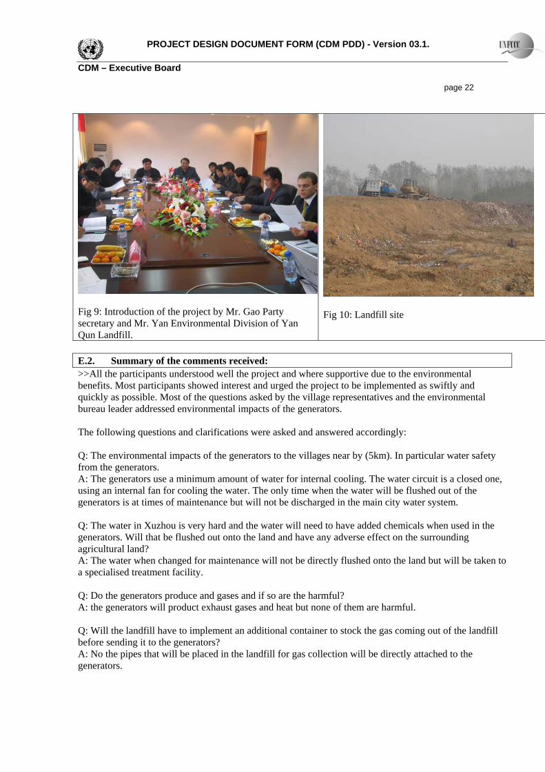
Fig 10: Landfill site
Fig 9: Introduction of the project by Mr. Gao Party secretary and Mr. Yan Environmental Division of Yan
un Landfill. Q
E.2. Summary of the comments received: >>All the participants understood well the project and where supportive due to the environmental benefits. Most participants showed interest and urged the project to be implemented as swiftly and quickly as possible. Most of the questions asked by the village representatives and the environmental bureau leader addressed environmental impacts of the generators. The following questions and clarifications were asked and answered accordingly: Q: The environmental impacts of the generators to the villages near by (5km). In particular water safety from the generators. A: The generators use a minimum amount of water for internal cooling. The water circuit is a closed one, using an internal fan for cooling the water. The only time when the water will be flushed out of the generators is at times of maintenance but will not be discharged in the main city water system. Q: The water in Xuzhou is very hard and the water will need to have added chemicals when used in the generators. Will that be flushed out onto the land and have any adverse effect on the surrounding agricultural land? A: The water when changed for maintenance will not be directly flushed onto the land but will be taken to a specialised treatment facility. Q: Do the generators produce and gases and if so are the harmful? A: the generators will product exhaust gases and heat but none of them are harmful. Q: Will the landfill have to implement an additional container to stock the gas coming out of the landfill before sending it to the generators? A: No the pipes that will be placed in the landfill for gas collection will be directly attached to the generators.
PROJECT DESIGN DOCUMENT FORM (CDM PDD) - Version 03.1. CDM – Executive Board page 23 Q: Will Sindicatum Carbon Capital chose the generators equipment? A: Yes SCC in consultation with Xuzhou landfill will chose the most appropriate and most modern generators as possible. Q: What are the costs of the operation? A: The costs are fully taken by SCC which means that there are no costs on local administration budgets or the landfill management. Q: Can the generators be dangerous for people near them? A: the generators will be enclosed in sound proof containers for safety issues and to minimise the amount of noise to the surrounding areas. Only trained staff will have direct access to the generators which means they pose no safety threats. Clarifications were asked on the collection system to the generators. A detailed explanation of the collection pipes and their connection was given as explained in the above sections. E.3. Report on how due account was taken of any comments received: >> Special attention will be given to how we dispose of the generator cooling water.
PROJECT DESIGN DOCUMENT FORM (CDM PDD) - Version 03.1. CDM – Executive Board page 24
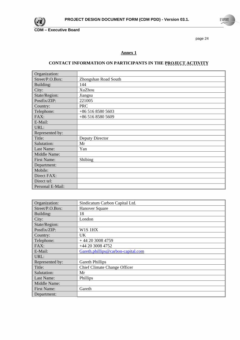
Annex 1
CONTACT INFORMATION ON PARTICIPANTS IN THE PROJECT ACTIVITY Organization: Street/P.O.Box: Zhongshan Road South Building: 144 City: XuZhou State/Region: Jiangsu Postfix/ZIP: 221005 Country: PRC Telephone: +86 516 8580 5603 FAX: +86 516 8580 5609 E-Mail: URL: Represented by: Title: Deputy Director Salutation: Mr Last Name: Yan Middle Name: First Name: Shibing Department: Mobile: Direct FAX: Direct tel: Personal E-Mail:
Organization: Sindicatum Carbon Capital Ltd. Street/P.O.Box: Hanover Square Building: 18 City: London State/Region: Postfix/ZIP: W1S 1HX Country: UK Telephone: + 44 20 3008 4759 FAX: +44 20 3008 4752 E-Mail: [email protected]: Represented by: Gareth Phillips Title: Chief Climate Change Officer Salutation: Mr Last Name: Phillips Middle Name: First Name: Gareth Department:

PROJECT DESIGN DOCUMENT FORM (CDM PDD) - Version 03.1. CDM – Executive Board page 25 Mobile: Direct FAX: Direct tel: Personal E-Mail:

PROJECT DESIGN DOCUMENT FORM (CDM PDD) - Version 03.1. CDM – Executive Board page 26
Annex 2
INFORMATION REGARDING PUBLIC FUNDING
No public funding is utilized.
PROJECT DESIGN DOCUMENT FORM (CDM PDD) - Version 03.1. CDM – Executive Board page 27
Annex 3
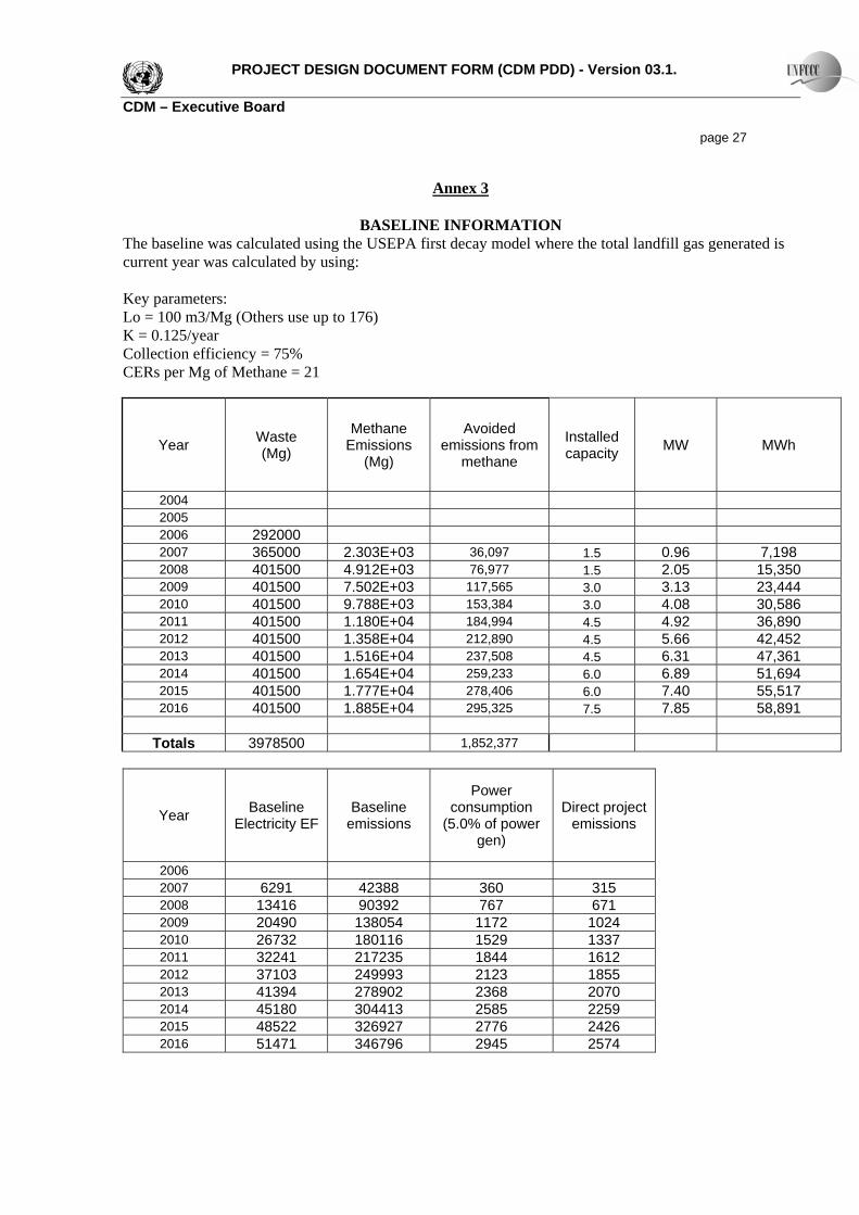
BASELINE INFORMATION The baseline was calculated using the USEPA first decay model where the total landfill gas generated is current year was calculated by using: Key parameters: Lo = 100 m3/Mg (Others use up to 176) K = 0.125/year Collection efficiency = 75% CERs per Mg of Methane = 21
Year Waste (Mg)
Methane Emissions
(Mg)
Avoided emissions from
methane
Installed capacity MW MWh
2004 2005 2006 292000 2007 365000 2.303E+03 36,097 1.5 0.96 7,198 2008 401500 4.912E+03 76,977 1.5 2.05 15,350 2009 401500 7.502E+03 117,565 3.0 3.13 23,444 2010 401500 9.788E+03 153,384 3.0 4.08 30,586 2011 401500 1.180E+04 184,994 4.5 4.92 36,890 2012 401500 1.358E+04 212,890 4.5 5.66 42,452 2013 401500 1.516E+04 237,508 4.5 6.31 47,361 2014 401500 1.654E+04 259,233 6.0 6.89 51,694 2015 401500 1.777E+04 278,406 6.0 7.40 55,517 2016 401500 1.885E+04 295,325 7.5 7.85 58,891
Totals 3978500 1,852,377
Year Baseline Electricity EF
Baseline emissions
Power consumption
(5.0% of power gen)
Direct project emissions
2006 2007 6291 42388 360 315 2008 13416 90392 767 671 2009 20490 138054 1172 1024 2010 26732 180116 1529 1337 2011 32241 217235 1844 1612 2012 37103 249993 2123 1855 2013 41394 278902 2368 2070 2014 45180 304413 2585 2259 2015 48522 326927 2776 2426 2016 51471 346796 2945 2574

PROJECT DESIGN DOCUMENT FORM (CDM PDD) - Version 03.1. CDM – Executive Board page 28
Totals 322,840 2,175,217 16,142
Annex 4
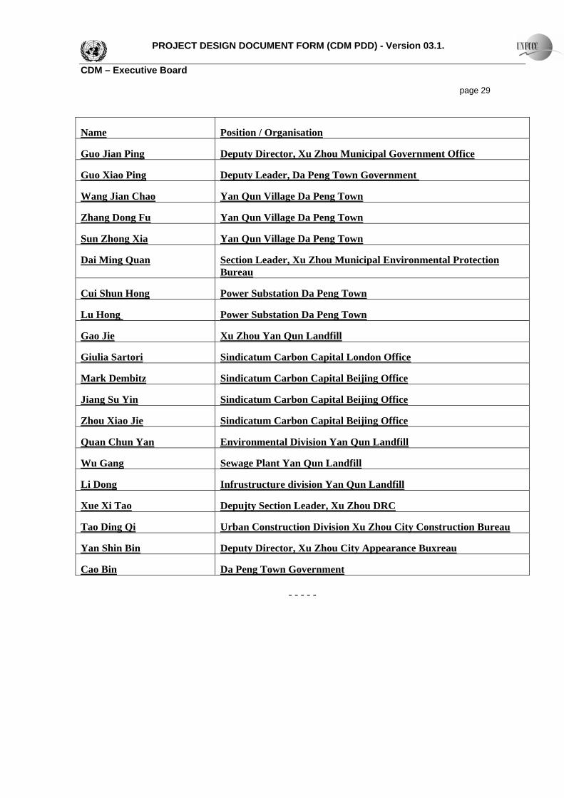
MONITORING INFORMATION Monitoring information given in section B APPENDIX 1: STAKEHOLDER CONSULTATION ATTENDEES
PROJECT DESIGN DOCUMENT FORM (CDM PDD) - Version 03.1. CDM – Executive Board page 29
Name Position / Organisation
Guo Jian Ping Deputy Director, Xu Zhou Municipal Government Office
Guo Xiao Ping Deputy Leader, Da Peng Town Government
Wang Jian Chao Yan Qun Village Da Peng Town
Zhang Dong Fu Yan Qun Village Da Peng Town
Sun Zhong Xia Yan Qun Village Da Peng Town
Dai Ming Quan Section Leader, Xu Zhou Municipal Environmental Protection Bureau
Cui Shun Hong Power Substation Da Peng Town
Lu Hong Power Substation Da Peng Town
Gao Jie Xu Zhou Yan Qun Landfill
Giulia Sartori Sindicatum Carbon Capital London Office
Mark Dembitz Sindicatum Carbon Capital Beijing Office
Jiang Su Yin Sindicatum Carbon Capital Beijing Office
Zhou Xiao Jie Sindicatum Carbon Capital Beijing Office
Quan Chun Yan Environmental Division Yan Qun Landfill
Wu Gang Sewage Plant Yan Qun Landfill
Li Dong Infrustructure division Yan Qun Landfill
Xue Xi Tao Depujty Section Leader, Xu Zhou DRC
Tao Ding Qi Urban Construction Division Xu Zhou City Construction Bureau
Yan Shin Bin Deputy Director, Xu Zhou City Appearance Buxreau
Cao Bin Da Peng Town Government
- - - - -


![Leachate Basic Design[1]](https://img.pdfslide.net/doc/110x75/54744d63b4af9f09648b45f9/leachate-basic-design1.jpg)