Embed Size (px)
Citation preview


Alberta Transportat ion ARCH-BEAM-CULVERT STRUCTURAL DESIGN GUIDELINES
The Cohos Evamy Partners
TABLE OF CONTENTS
Page No.
DISCLAIMER.......................................................................................................................................... I
1. STRUCTURAL DESIGN GUIDELINES ..................................................................................... 1
2. GENERAL REQUIREMENTS (FIGURE B.2, STEP 1) .............................................................. 1
3. GENERAL LAYOUT AND GEOMETRY (FIGURE B.2, STEP 2) ............................................. 1
4. LOADS (FIGURE B.2, STEP 3) ................................................................................................. 2
5. MATERIALS (FIGURE B.2, STEP 4) ......................................................................................... 2
6. EQUILIBRIUM OF ARCH-BEAM-CULVERT (FIGURE B.2, STEP 5)....................................... 3
7. DEAD LOAD DESIGN ACTIONS (FIGURE B.2, STEP 6) ........................................................ 3
8. LIVE LOAD DESIGN MOMENTS FOR ROOF SLAB (FIGURE B.2, STEP 7)......................... 4
9. LIVE LOAD DESIGN SHEARS FOR ROOF SLAB, MOMENTS AND SHEARS FORHORIZONTAL ARM, AND AXIAL FORCE IN CULVERT WALL (FIGURE B.2, STEP 8)....... 5
10. DESIGN ROOF SLAB AND ARMS FOR SHEAR AT ULTIMATE LIMIT STATE(FIGURE B.2, STEP 9)............................................................................................................... 6
11. CULVERT TOP PLATE STRENGTH IN TENSION (FIGURE B.2, STEP 10).......................... 6
12. DESIGN ROOF SLAB AND ARMS FOR FLEXURE AND AXIAL LOADS ATULTIMATE LIMIT STATE (FIGURE B.2, STEP 11)................................................................... 6
13. SHEAR CONNECTORS FOR ULTIMATE LIMIT STATE (FIGURE B.2, STEP 12) ................ 7
14. TRANSFER OF AXIAL FORCE FROM CULVERT TO SLAB (FIGURE B.2, STEP 13)......... 7
15. SERVICE LOAD RESISTANCE OF BOLTED JOINTS (FIGURE B.2, STEP 14).................... 7
16. FATIGUE LIMIT STATE STRESSES AND FORCES (FIGURE B.2, STEP 15) ..................... 7
17. FATIGUE RESISTANCE (FIGURE B.2, STEPS 16, 17 AND 18) ............................................. 8
18. DISTRIBUTION REINFORCEMENT (FIGURE B.2, STEP 19) ................................................. 8
19. CULVERT PLATE AND SEAM STRENGTH IN COMPRESSION(FIGURE B.2, STEPS 20 AND 21)............................................................................................. 8
20. SOIL CAPACITY UNDER ARMS AND ADJACENT TO CULVERT SIDE WALLS
(FIGURE B.2, STEP 22)............................................................................................................. 9
21. HEADWALL BEAMS AND FOOTINGS (FIGURE B.2, STEP 23) ............................................. 9
i

Alberta Transportat ion ARCH-BEAM-CULVERT STRUCTURAL DESIGN GUIDELINES
The Cohos Evamy Partners i
DISCLAIMER
The material presented in these structural design guidelines has been prepared inaccordance with generally recognized engineering principles and practices for AlbertaTransportation. These guidelines should only be used by qualified consultants designingstructures for Alberta Transportation. In using the guidelines, the principles of CAN/CSA-S6-00, “Canadian Highway Bridge Design Code” must be applied, and appropriateengineering judgment used.
CONTACT
Questions or further information on this guideline may be directed to Raymond Yu, P.Eng.,Structural Standards Engineer, Alberta Transportation (780) 415-1016

Alberta Transportat ion ARCH-BEAM-CULVERT STRUCTURAL DESIGN GUIDELINES
The Cohos Evamy Partners 1
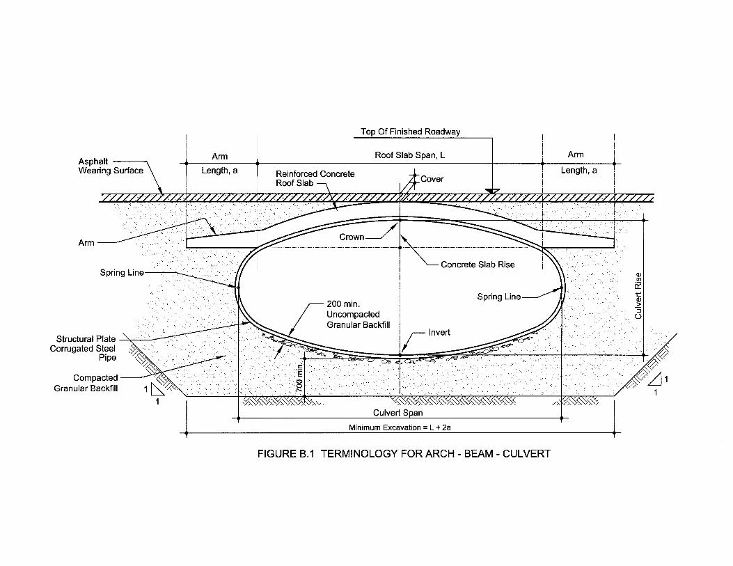
1. STRUCTURAL DESIGN GUIDELINES
Figure B.1 shows the Arch-Beam-Culvert system. The system consists of a structural platecorrugated steel pipe, surrounded by compacted granular backfill, with a reinforced concreteslab on top. Horizontal arms project transversely from the slab, beyond the steel pipe oneither side of the structure. The slab acts compositely with the corrugated steel pipe to resistload from fill placed above and vehicular traffic passing over top of the structure.
Arch-Beam-Culverts are normally used in installations where the depth of cover (Figure B.1)is small.
Figure B.2 provides a flow chart that can be used to organize the structural designcalculations for these structures.
2. GENERAL REQUIREMENTS (Figure B.2, Step 1)
Arch-Beam-Culverts shall be designed to conform to the requirements of CAN/CSA-S6-00.Normally, the design life of these structures will be 75 years.
For sites with highly corrosive environmental conditions, it may not be possible to achievethe design life of 75 years required by Clause 1.5.2.3. As part of the normal evaluationprocess, the potential for early replacement should be considered and Arch-Beam-Culvertsshould be compared to other structural alternatives using life-cycle cost analysis.
Prior to initiating structural design, geotechnical, hydraulic, and corrosion investigations forthe site must be undertaken by qualified specialists.
3. GENERAL LAYOUT AND GEOMETRY(Figure B.2, Step 2)
The general layout and cross-sectional geometry for the Arch-Beam-Culvert shall beselected to satisfy the requirements of the project.
Roof slab span lengths, L, shall be limited to the range of 5 to 10 m. Rise-to-span ratios forthe roof slab shall be no larger than 0.2. The lengths of the horizontal arms shall be not lessthan 0.15 L.
The minimum roof slab span to culvert span ratio shall be 0.875.

Alberta Transportat ion ARCH-BEAM-CULVERT STRUCTURAL DESIGN GUIDELINES
The Cohos Evamy Partners 2
The minimum thicknesses of the culvert plates shall be not less than those required for aculvert of the same dimensions meeting the minimum cover requirements of CAN/CSA-S6-00, Clause 7.6.3.1. In addition, the minimum thickness of the top and side plates shall be5 mm to allow for the welding of studs and for durability considerations. The minimumthickness of the bottom plates shall be 4 mm.
The minimum bottom width of the excavation and compacted granular backfill shall be(L + 2a). A 200 mm thick layer of uncompacted granular backfill shall be placed below thebottom plates.
4. LOADS (Figure B.2, Step 3)
The load factors and load combinations used for the design of conventional bridge structuresshall be used for the proportioning of Arch-Beam-Culverts.
The design live load in Alberta is the CL800 Truck. For live load effects, the dynamic loadallowance for arch type buried structures in accordance with Clause 3.8.4.5.2 shall be used.It should be noted that where asphaltic wearing surface is placed directly in contact with thecrown of the roof slab, it is not considered as earth cover and there will be no reduction indynamic load allowance.
Where appropriate, an allowance should be made for the dead load from an additional100 mm thickness of wearing surface placed at some time in the future.
Temporary supports are generally placed 30 mm below the top plates prior to pouring theroof slab concrete when the roof slab is cast. All loads including the weight of the slab, thesoil and asphalt wearing surface within the slab span above the roof, and live loads shall becarried by the composite roof slab.
5. MATERIALS (Figure B.2, Step 4)
Structural Plate Corrugated Steel Pipe shall be in accordance with the current edition of CSAG401. The designer may consider the increase in yield strength that occurs as a result ofcold working of the corrugated plates during manufacturing when substantiated by theappropriate test results.
High quality backfill is required around Arch-Beam-Culverts to ensure that the structuralperformance is satisfactory.
Reinforcing bars shall be epoxy coated.
Class SF concrete shall be used for Class A Highways. Class C concrete is acceptable forClass B and lesser highways.

Alberta Transportat ion ARCH-BEAM-CULVERT STRUCTURAL DESIGN GUIDELINES
The Cohos Evamy Partners 3
6. EQUILIBRIUM OF ARCH-BEAM-CULVERT (Figure B.2, Step 5)
The analytical model shown in Figure B.3 may be used to determine the dead load designactions and live load bending moments in a one metre wide strip of the structure.
Figure B.3(a) shows the free body diagram of the roof slab and the soil above. In this figure,Wr is the weight of the roof slab, Ws is the weight of the soil and W is the portion of truckwheel load distributed to the one metre wide strip. At node B, MD is the dead load moment,ML is the moment from wheel load, HD is the dead load axial force, and HL is the axial forcefrom wheel load. At node A, Mr, Vr and Hr are the roof slab moment, vertical force andhorizontal force, respectively. Horizontal forces HS1 and HS2 are the resultant forces fromhorizontal soil pressures. In this figure Ko is the at-rest horizontal earth pressure coefficientand γ is the unit weight of the backfill.
Figure B.3(b) shows the free body diagram for node A. The moments, M, vertical forces, V,and horizontal forces, H, have subscripts r, a and c to represent the roof slab, horizontal armand culvert wall below, respectively.
Figure B.3(c) shows the free body diagram for the horizontal arm. The distance along thearm to the resultant vertical reaction from soil pressures below is assumed to be 0.5a.
As a conservative simplification when using Figure B.3 for the design of the roof slab, it maybe assumed that 75 percent of the vertical load on the roof slab is carried by the culvertsidewall and the remainder by the horizontal arm. For the design of the culvert side wall, itmay be assumed that 100 percent of the vertical load on the roof slab is carried by theculvert wall below.
If the depth of soil cover above the slab is small, the resultant forces from horizontal soilpressures may be ignored. In the design of the roof slab for shear and bending moment, it isgenerally conservative to neglect the horizontal forces Hr, HD, and HL.
7. DEAD LOAD DESIGN ACTIONS (Figure B.2, Step 6)
Once the dead loads are determined from the geometry, the analytical model in Figure B.3may be used to calculate the dead load actions for the design of the Arch-Beam-Culvert.

Alberta Transportat ion ARCH-BEAM-CULVERT STRUCTURAL DESIGN GUIDELINES
The Cohos Evamy Partners 4
8. LIVE LOAD DESIGN MOMENTS FOR ROOF SLAB(Figure B.2, Step 7)
Once the portion of the wheel load distributed to the one metre wide strip in Figure B.3 isdetermined, the analytical model may be used to calculate the live load longitudinal bendingmoments for the design of the roof slab at the ultimate, serviceability and fatigue limit states.It may be assumed that the second two axles of the design truck are positionedsymmetrically over the centre of the structure.
The provisions of CAN/CSA-S6-00, Clause 5.7.1.2 may be used to determine the truckwheel load distribution. The distribution for longitudinal bending at the ultimate andserviceability limit states may be determined from [Clause 5.7.1.2.1(b)]
e
Lm
wheel BnRF2
Mm
ondistributiloadWheel == (1)
The distribution for bending at the fatigue limit state may be determined from[Clause 5.7.1.2.2(d)]
e
m
wheel B
F2
Mm
ondistributiloadWheel == (2)
In these equations, m is the maximum longitudinal moment per metre width, Mwheel is themaximum moment for a line of wheel loads, Fm is an amplification factor to account fortransverse variation in maximum longitudinal moment intensity compared to averagelongitudinal moment intensity, n is the number of design lanes and Be is the effective barrellength of the Arch-Beam-Culvert. These parameters are defined further in CAN/CSA-S6-00.
The effective barrel length shall be taken as not more than the clear roadway width betweenguardrails plus 0.5 m on either side.
In determining the wheel load distribution and design moments, the span should be taken asthe roof slab span, L.

Alberta Transportat ion ARCH-BEAM-CULVERT STRUCTURAL DESIGN GUIDELINES
The Cohos Evamy Partners 5
9. LIVE LOAD DESIGN SHEARS FOR ROOF SLAB,MOMENTS AND SHEARS FOR HORIZONTAL ARM,AND AXIAL FORCE IN CULVERT WALL (Figure B.2, Step 8)
The provisions of CAN/CSA-S6-00, Clauses 5.7.1.4.1(b) and 5.7.1.4.2 may be used todetermine the live load longitudinal vertical shears near the mid-span of roof slabs. Thespan of the roof slab shall be taken as L.
Near the ends of the slab, the live load longitudinal vertical reaction for all of the design laneson the structure shall be distributed uniformly over an effective width equal to the sum of thelane widths plus the sum of the depth of fill and one-half of the slab thickness on either sideof the lanes. The effective width calculated in this way must be less than the barrel length ofthe structure.
In determining the live load longitudinal vertical reaction per metre width near the ends of theslab, the wheel loads may be distributed parallel to the span in accordance with Clause7.6.2.1.3. The live load reaction shall be multiplied by the appropriate modification factor formultilane loading.
For design, the live load longitudinal vertical reaction per metre width near the ends of theroof slab may be resolved into a radial shear component and a tangential axial forcecomponent.
In determining the resultant vertical reaction from soil pressures, Va, in Figure B.3(c), for thedesign of the horizontal arm at the ultimate and fatigue limit states, the live load reaction fromwheel load may be taken as 50 percent of the uniformly distributed live load longitudinalvertical reaction per metre width at the ends of the roof slab.
The culvert side wall immediately below the roof slab should be proportioned to resist 100percent of the uniformly distributed live load longitudinal vertical reaction per metre widthfrom the roof slab at the ultimate limit state. The live load axial force per metre width in theculvert wall is equal to the design live load reaction per metre width divided by the sine of theangle the wall makes with the horizontal.
The potential for the settlement of the soil under the horizontal arms shall be taken intoconsideration in the design of the arms and the culvert wall below the arms.

Alberta Transportat ion ARCH-BEAM-CULVERT STRUCTURAL DESIGN GUIDELINES
The Cohos Evamy Partners 6
10. DESIGN ROOF SLAB AND ARMS FOR SHEAR ATULTIMATE LIMIT STATE (Figure B.2, Step 9)
The requirements of CAN/CSA-S6-00, Clause 8.9.4 for beam action should be used toproportion the roof slab and horizontal arms to resist the design shears.
The requirements of Clause 8.9.4 should be used to check the roof slab for two-way shearunder the action of truck wheel loads. The critical location will be near the slab mid-spanwhere the wheel loads are applied directly on the roof slab.
Shear strength requirements will normally control the thickness of the roof slab. The slabthickness should be selected so that no shear reinforcement is required.
11. CULVERT TOP PLATE STRENGTH IN TENSION(Figure B.2, Step 10)
The culvert top plate acts compositely with the roof slab to resist bending moments. Theculvert wall strength in tension is needed to determine the flexural strength of the compositeroof slab.
The axial tensile resistance of the culvert top plate may be determined from Clause 10.8.2using a resistance factor for the culvert steel of 0.85.
The tension capacity of the culvert at longitudinal seams between adjacent structural platecorrugated steel pipe sections may be determined by calculating the shear resistance of thebolted connections. Clause 10.18.2.2.2 may be used to check the bearing resistance of theculvert wall adjacent to bolts and the shear resistance of bolts using a resistance factor of0.67. Calculations should assume that bolt threads are intercepted by a shear plane.
12. DESIGN ROOF SLAB AND ARMS FOR FLEXURE ANDAXIAL LOADS AT ULTIMATE LIMIT STATE (Figure B.2, Step 11)
The requirements of CAN/CSA-S6-00, Clause 8.8 should be used to proportion the roof slaband horizontal arms to resist the design moments.
In designing the roof slab for longitudinal bending moment, the culvert top plate and thecircumferential reinforcing steel may be considered as the flexural reinforcement. Thecontribution of the culvert top plate is limited to the tensile capacity determined in Figure B.2,Step 10.

Alberta Transportat ion ARCH-BEAM-CULVERT STRUCTURAL DESIGN GUIDELINES
The Cohos Evamy Partners 7
13. SHEAR CONNECTORS FOR ULTIMATE LIMIT STATE(Figure B.2, Step 12)
The tensile force in the culvert wall at the ultimate limit state must be developed between thepoint of maximum moment in the composite roof slab and the location of minimum momentat the intersection of the horizontal arm and the culvert.
CAN/CSA-S6-00, Clause 10.11.8.3 may be used to determine the number of connectorsrequired to transfer this force.
14. TRANSFER OF AXIAL FORCE FROM CULVERT TO SLAB (Figure B.2, Step 13)
The shear connectors between the culvert wall and the roof slab must transfer the axial forcein culvert below into the roof slab.
CAN/CSA-S6-00, Clause 10.11.8.3 may be used to determine the number of connectorsrequired. These shear connectors are in addition to those determined in Figure B.2, Step 12.
15. SERVICE LOAD RESISTANCE OF BOLTED JOINTS(Figure B.2, Step 14)
The service load tension in the longitudinal bolted joints between adjacent structural platecorrugated steel pipe sections may be determined by the cracked transformed sectionapproach.
When the factored tensile resistance calculated from Step 10 is limited to less than 55percent of the unfactored seam strength in compression, service load deformations of thebolted splices should be acceptable and no further investigation will be required.
16. FATIGUE LIMIT STATE STRESSES AND FORCES(Figure B.2, Step 15)
The stresses in the culvert top plate and circumferential reinforcing steel in the compositeroof slab at the fatigue limit state may be determined by the cracked transformed sectionapproach.

Alberta Transportat ion ARCH-BEAM-CULVERT STRUCTURAL DESIGN GUIDELINES
The Cohos Evamy Partners 8
17. FATIGUE RESISTANCE (Figure B.2, Steps 16, 17 and 18)
For the top plate portion of the culvert acting compositely with the roof slab, the longitudinalseams between adjacent plate sections shall be assessed for structural fatigue using Clause10.17 of CAN/CSA-S6-00. Stresses should be checked at the net section of the culvert wallfor the fatigue stress range resistance determined from the average of the resistances fordetail categories (C) and (D).
CAN/CSA-S6-00, Clause 8.5.3.1 should be used to determine the fatigue resistance ofreinforcing steel in the composite slab.
CAN/CSA-S6-00, Clause 10.17.2.6 may be used to determine the fatigue resistance of thestuds connecting the culvert wall to the concrete roof slab.
18. DISTRIBUTION REINFORCEMENT (Figure B.2, Step 19)
Distribution reinforcement is required to resist the transverse moments in the roof slab.
The transverse reinforcement should be sized to resist a transverse bending moment of 30percent of the maximum longitudinal moment from truck loading at the ultimate limit state.
The amount of transverse reinforcement shall be not less than that required by Clause8.18.7.
19. CULVERT PLATE AND SEAM STRENGTH IN COMPRESSION(Figure B.2, Steps 20 and 21)
For the portion of the culvert below the horizontal arms, the wall strength and seam strengthin compression shall be reviewed for the factored axial forces using the procedures in Clause7.6 of CAN/CSA-S6-00.
In reviewing the culvert wall strength using Clause 7.6.2.2, the modified modulus of soilstiffness should be used, the factor ������������ ���������� ���������� ������accounting for depth of cover, ρ, may be taken as 1.0.
The continuous longitudinal seam between the side plates and the top plates near the end ofthe roof slab shall be detailed as shown in Figure B.4.
Alberta Transportat ion ARCH-BEAM-CULVERT STRUCTURAL DESIGN GUIDELINES
The Cohos Evamy Partners 9
20. SOIL CAPACITY UNDER ARMS AND ADJACENTTO CULVERT SIDE WALLS (Figure B.2, Step 22)
The soil capacity for vertical loads transferred by the horizontal arms to the backfill belowand the horizontal soil pressure adjacent to the side walls of the culvert should be reviewed.
The vertical soil pressures under the arms and the horizontal soil pressures adjacent to theculvert side walls shall not exceed 500 kPa and 650 kPa for the serviceability and ultimatelimit states, respectively.
21. HEADWALL BEAMS AND FOOTINGS (Figure B.2, Step 23)
Headwall beams are normally placed at the ends of the Arch-Beam-Culverts to stiffen thestructure and retain soil. These beams shall be supported on spread footings.
Unless a refined analysis is undertaken, the headwall beams shall be proportioned tosupport a single line of truck wheel loads applied in the vertical direction and soil pressuresapplied in the horizontal direction.
The resultant vertical force acting on the soil below the spread footings supporting the endsof the headwall beams shall be taken as 100 percent of the vertical reactions from dead andlive loads at the end of the beam.

Alberta Transportat ion ARCH-BEAM-CULVERT STRUCTURAL DESIGN GUIDELINES
The Cohos Evamy Partners
START
General Requirements• Design Life• Geotechnical Requirements• Hydraulic Requirements• Corrosion Requirements
1
Establish:• Load Factors and Load Combinations
[CAN/CSA-S6-00, Clause 3.5]• Dead Loads
[CAN/CSA-S6-00, Clause 3.6]• Live Load
[CAN/CSA-S6-00, Clause 3.8]• Dynamic Load Allowance
[CAN/CSA-S6-00, Clause 3.8.4.5]
2
FIGURE B.2: FLOW CHART FOR THE DESIGN OF ARCH-BEAM-CULVERTS
Select General Layout andCross-Sectional Geometry
3

Alberta Transportat ion ARCH-BEAM-CULVERT STRUCTURAL DESIGN GUIDELINES
The Cohos Evamy Partners
Select Materials:• Structural Plate Corrugated Steel Pipe• Compacted Granular Backfill• Concrete• Reinforcing Steel• Shear Studs
4
Determine Live Load Moments For Roof Slab:• Longitudinal Bending Moment for
Ultimate and Serviceability Limit States[CAN/CSA-S6-00, Clause 5.7.1.2.1(b)]
• Longitudinal Bending Moment forFatigue Limit States[CAN/CSA-S6-00, Clause 5.7.1.2.2(d)]
• Figure B.3
5 Equilibrium of Arch-Beam-Culvert• Figure B.3
7
FIGURE B.2 (CONT’D)
6 Determine Dead Load Design Actions• Figure B.3

Alberta Transportat ion ARCH-BEAM-CULVERT STRUCTURAL DESIGN GUIDELINES
The Cohos Evamy Partners
Determine Live Load Shears For Roof Slab,Moments and Shears For Horizontal ArmAnd Axial Force In Culvert Wall• Longitudinal Vertical Shear for
Ultimate and Serviceability Limit States[CAN/CSA-S6-00, Clause 5.7.1.4.1(b)]
• Longitudinal Vertical Shear forFatigue Limit States[CAN/CSA-S6-00, Clause 5.7.1.4.2]
• Distribute Wheel Loads Through FillNear Ends of Slab [CAN/CSA-S6-00,Clause 7.6.2.1.3]
• Figure B.3
8
FIGURE B.2 (CONT’D)
Determine Culvert Top Plate StrengthIn Tension [CAN/CSA-S6-00,Clauses 10.8.2 and 10.18.2.2.2]
10
Design Roof Slab And Arms For Flexureand Axial Loads At Ultimate Limit State[CAN/CSA-S6-00, Clause 8.8]
11
Shear Connectors For Ultimate Limit State[CAN/CSA-S6-00, Clause 10.11.8.3]
12
Design Roof Slab And Arms For ShearAt Ultimate Limit State [CAN/CSA-S6-00, Clauses 8.9.4.2 and 8.9.4.3]
9

Alberta Transportat ion ARCH-BEAM-CULVERT STRUCTURAL DESIGN GUIDELINES
The Cohos Evamy Partners
FIGURE B.2 (CONT’D)
Determine Fatigue Limit State Stressesand Forces
15
Check Fatigue Resistance of Culvert Wall[CAN/CSA-S6-00,Clauses 10.17.2.2 and 10.17.2.3]
16
Check Fatigue Resistance of Reinforcing Steel[CAN/CSA-S6-00, Clause 8.5.3.1]
17
Check The Service Load Resistance Of TheBolted Joints In The Connections BetweenAdjacent Plate Sections
14
Provide Additional Shear ConnectorsTo Transfer Axial Force From The Culvert WallNear The Ends Of The Span To The Roof Slab
13

Alberta Transportat ion ARCH-BEAM-CULVERT STRUCTURAL DESIGN GUIDELINES
The Cohos Evamy Partners
Check Shear Connectors forFatigue Resistance[CAN/CSA-S6-00, Clause 10.17.2.6]
Provide Distribution Reinforcement[CAN/CSA-S6-00, Clause 8.18.7]
19
18
Review Culvert Wall Strength,Check Side and Bottom Plate Thicknesses[CAN/CSA-S6-00, Clause 7.6.2.2]
20
Review Culvert Seam Strength[CAN/CSA-S6-00, Clause 7.6.2.4]
21
FIGURE B.2 (CONT’D)

Alberta Transportat ion ARCH-BEAM-CULVERT STRUCTURAL DESIGN GUIDELINES
The Cohos Evamy Partners
k:\buildings\e00702\01\admin\reports\abc struct design guidelines.doc
Soil Capacity• Review Bearing Capacity of Soil Under Arms
[CAN/CSA-S6-00, Clause 6.7.2]• Check Horizontal Soil Pressure Adjacent To
Side Walls
22
END
FIGURE B.2 (CONT’D)
Design Headwall Beams and Footings:
• Select Geometry• Determine Wheel Load Distribution
[CAN/CSA-S6-00, Clause 8.18.6]• Determine Design Shear Forces
and Bending Moments• Design for Flexure At Ultimate Limit State
[CAN/CSA-S6-00, Clause 8.8.4.1]• Design For Shear At Ultimate Limit State
[CAN/CSA-S6-00, Clause 8.9.4.2]• Design Spread Footings Supporting
Headwall Beams
23