Embed Size (px)
Citation preview

2
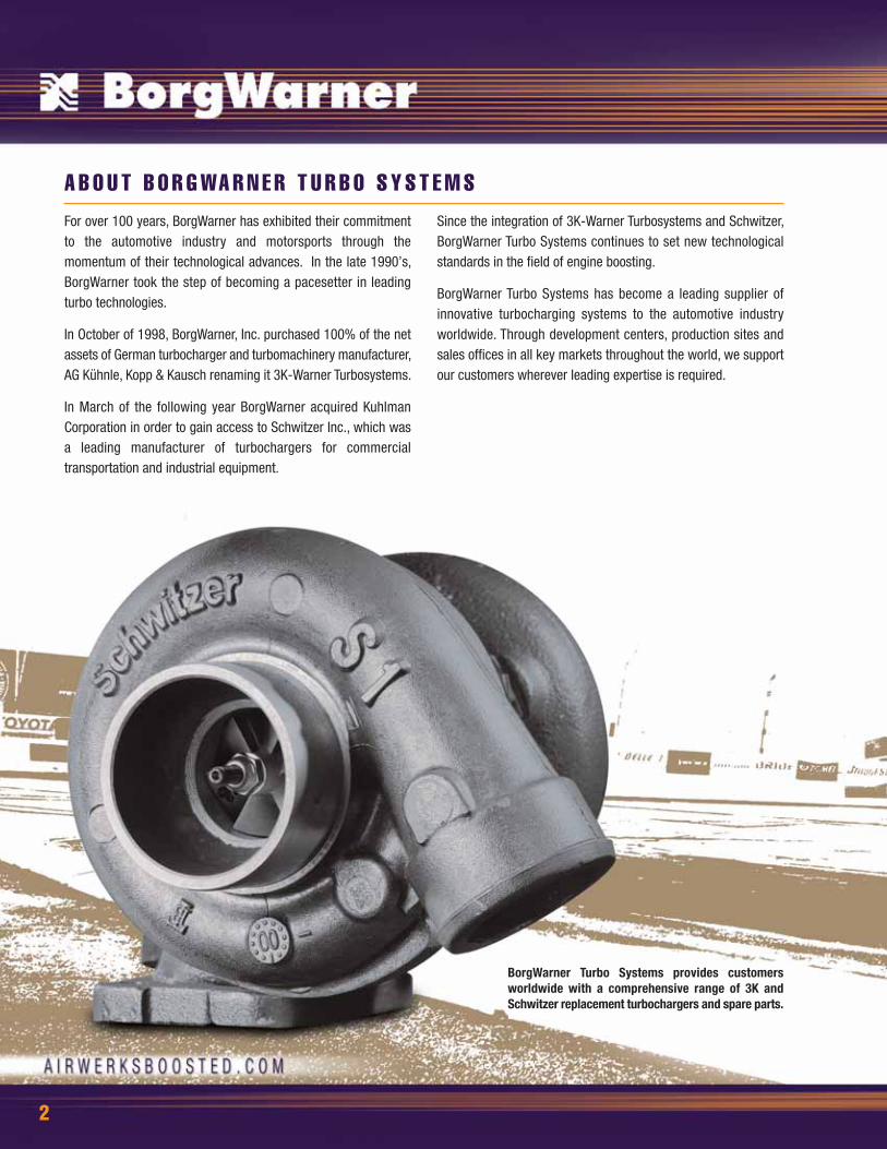
For over 100 years, BorgWarner has exhibited their commitmentto the automotive industry and motorsports through themomentum of their technological advances. In the late 1990’s,BorgWarner took the step of becoming a pacesetter in leadingturbo technologies.
In October of 1998, BorgWarner, Inc. purchased 100% of the netassets of German turbocharger and turbomachinery manufacturer,AG Kühnle, Kopp & Kausch renaming it 3K-Warner Turbosystems.
In March of the following year BorgWarner acquired KuhlmanCorporation in order to gain access to Schwitzer Inc., which wasa leading manufacturer of turbochargers for commercialtransportation and industrial equipment.
Since the integration of 3K-Warner Turbosystems and Schwitzer,BorgWarner Turbo Systems continues to set new technologicalstandards in the field of engine boosting.
BorgWarner Turbo Systems has become a leading supplier ofinnovative turbocharging systems to the automotive industryworldwide. Through development centers, production sites andsales offices in all key markets throughout the world, we supportour customers wherever leading expertise is required.
A B O U T B O R G WA R N E R T U R B O S Y S T E M S
BorgWarner Turbo Systems provides customersworldwide with a comprehensive range of 3K andSchwitzer replacement turbochargers and spare parts.

3
Commitment to Performance. . . . . .4BorgWarner Trophy. . . . . . . . . . . . . . . . . . .5New Products . . . . . . . . . . . . . . . . . . . . . . 6 -7Te s t i m o n i a l s . . . . . . . . . . . . . . . . . . . . . . . . . 8Extended Tip Techno logy. . . . . . . . . 9Compressor Select ion. . . . . . . .10-11S 1 B . . . . . . . . . . . . . . . . . . . . . . . . . . . . . . . . . . . . 1 2S1BG . . . . . . . . . . . . . . . . . . . . . . . . . . . . . . . . . . . 13S2B . . . . . . . . . . . . . . . . . . . . . . . . . . . . . . . . . . . . . 14S200 . . . . . . . . . . . . . . . . . . . . . . . . . . . . . . . . . . . . 15S200SX. . . . . . . . . . . . . . . . . . . . . . . . . . . . . . . . . .16S300SX3. . . . . . . . . . . . . . . . . . . . . . . . . . . .17-18S 3 0 0 S . . . . . . . . . . . . . . . . . . . . . . . . . . . . . . . . 1 9S300G. . . . . . . . . . . . . . . . . . . . . . . . . . . . . . . . . . .20ABOUT S400SX. . . . . . . . . . . . . . . . . . . . . . 21S400SX3. . . . . . . . . . . . . . . . . . . . . . . . . . . . . . . .22S400SX4. . . . . . . . . . . . . . . . . . . . . . . . . . . .23-24S510. . . . . . . . . . . . . . . . . . . . . . . . . . . . . . . . . . . . .25BV50. . . . . . . . . . . . . . . . . . . . . . . . . . . . . . . . . . . . . .26K03-2072. . . . . . . . . . . . . . . . . . . . . . . . . . . . . .27K 0 3 - 2 0 7 5 . . . . . . . . . . . . . . . . . . . . . . . . . . . . 2 8K04-2075 . . . . . . . . . . . . . . . . . . . . . . . . . 29-30K04-2275 . . . . . . . . . . . . . . . . . . . . . . . . . . . . . 31K16-2467. . . . . . . . . . . . . . . . . . . . . . . . . . . . . .32K 2 6 . . . . . . . . . . . . . . . . . . . . . . . . . . . . . . . . . . . . 3 3K27-3072. . . . . . . . . . . . . . . . . . . . . . . . . . . . . . .34K29-3775. . . . . . . . . . . . . . . . . . . . . . . . . . . . . .35Reference. . . . . . . . . . . . . . . . . . . . . . . . . .36-38Warranty. . . . . . . . . . . . . . . . . . . . . . . . . . . . . . . .39

4
BorgWarner-AirWerks is an independent aftermarket program from BorgWarner Turbo Systems. This venture is focused oncreating exceptionally high engine performance through forcedinduction technology.
Why do the world’s most prominent auto manufacturers selectproducts from BorgWarner Turbo Systems? Simply put, we are the world leader in turbos for high speed, high temperature gasoline engines.
The BorgWarner performance line features an assortment ofcarefully chosen K and S series turbochargers to meet a widearray of high-performance engine requirements. These turbos willbe steadily improved based on the latest findings in aerodynamicand materials technology.
C O M M I T M E N T T O P E R F O R M A N C E
Racing has long been known as a fertile research and developmentarena and proving ground for new technology. BW-AirWerks takesfull advantage of its rich racing heritage using some of the same
materials and aerodynamic techniques that produced boost forwinning cars, elevating and incorporating it into the hardwareavailable through BorgWarner Turbo Systems.
R A C I N G I M P R O V E S O U R B R E E D
Audi 90 (Quattro) GTO was one of the most technologically advanced four-door race cars toever hit the tracks. The 1988 Trans Am Manufacturer's champion was banned from the 1989 season due to its dominance. Boost was provided by a single BW K-series turbocharger.

5
In 1936, Eddie Rickenbacker of the Indianapolis Speedway unveiled theBorgWarner Trophy and officially announced it as the prize for the champions ofthe Indy 500.
Commissioned by The BorgWarner Automotive Company in 1935, the trophy ismade of sterling silver standing over 5 feet and weighing nearly 155 pounds.The Trophy bears the likeness of every driver that has won the Indy 500 since1911 along with their victory date, and average speed in a checkerboard pattern.
Today the trophy is housed in the Hall of Fame Museum at the Indianapolis MotorSpeedway. The first Indy 500 champion that accepted the trophy, Louis Meyershortly after receiving it said, "Winning the Borg-Warner Trophy is like winningan Olympic medal."
T H E B O R G WA R N E R T R O P H Y
6
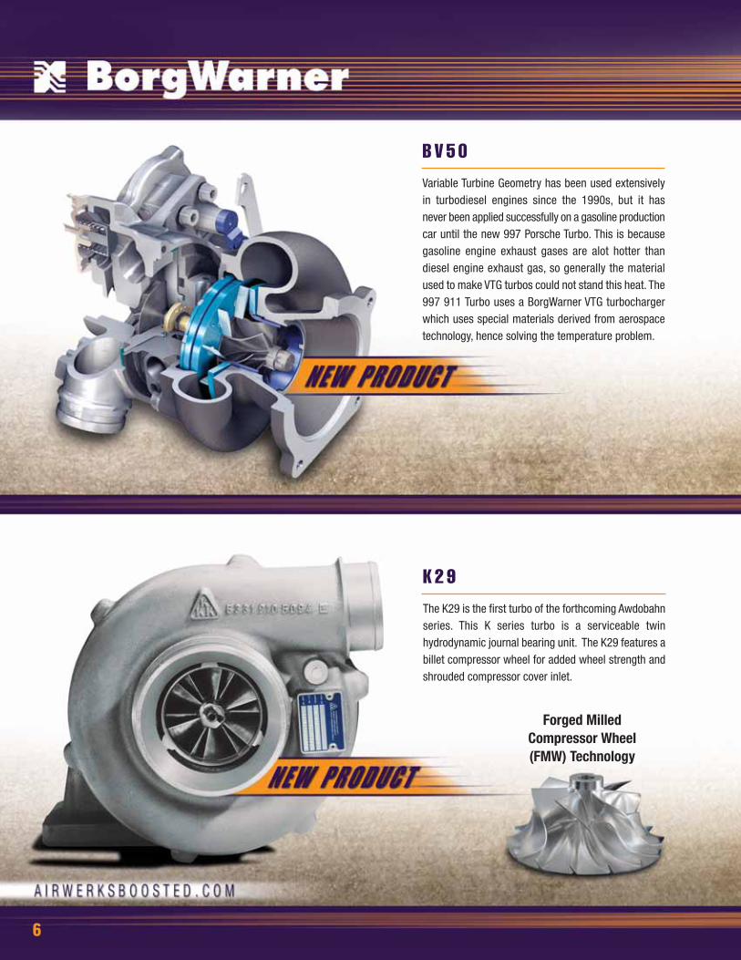
Variable Turbine Geometry has been used extensivelyin turbodiesel engines since the 1990s, but it has never been applied successfully on a gasoline productioncar until the new 997 Porsche Turbo. This is becausegasoline engine exhaust gases are alot hotter thandiesel engine exhaust gas, so generally the materialused to make VTG turbos could not stand this heat. The997 911 Turbo uses a BorgWarner VTG turbochargerwhich uses special materials derived from aerospacetechnology, hence solving the temperature problem.
B V 5 0
The K29 is the first turbo of the forthcoming Awdobahnseries. This K series turbo is a serviceable twinhydrodynamic journal bearing unit. The K29 features abillet compressor wheel for added wheel strength andshrouded compressor cover inlet.
K 2 9
Forged Milled Compressor Wheel (FMW) Technology

7
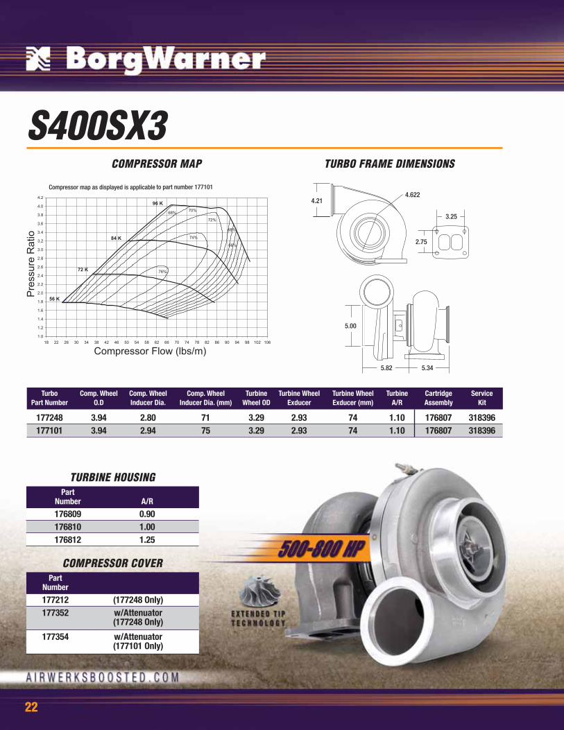
S400SX3 turbos were designed specifically to bolt-intoexisting high performance applications and offernumerous unique turbine housing configurations for avariety of application requirements. This turbo featuresextended-tip technology for quick rotor response andhigh pressure ratios.
S 4 0 0 S X 3
S400SX4 is a serviceable twin hydrodynamic journalbearing turbo that excels due to a high-pressure ratiocompressor stage utilizing extended-tip technology anda high efficiency turbine stage. This specialized turboconfiguration provides ultra-fast response and morethan 70 PSI of boost
S 4 0 0 S X 4

8
T E S T I M O N I A L S
S T U C K E Y R A C I N GAs crew chief for Stuckey Racing, the advantage we have is the tremendous mapping range of the S400-S500 compound setup. It’s been the extra edge over the competition that has kept us in the winner’s circlesince we began our program over 5 years ago. We are grateful to the BorgWarner engineers that createdthe extended tip technology that has helped advance the level of engine performance in the diesel truckcommunity. Thanks again for your commitment to turbocharger technology.
-Robert DonalsonCrew Chief
Do you have Airwerks on your Side? WE DO!!!!!! Which Equals holding "National Records." I as driver ofStuckey Racing's Pro-Steet Dodge would like to personally thank each and every member of Team Airwerks,their commitment and dedication to our program has been essential to us in providing back 2 back NationalChampionships and Records to our sponsors and most important, Fans!!!!
-Philip PalmerDriver
K I G G LY R A C I N GI've had nothing but great experiences with Borg Warner Airwerks turbos. They spool better than anythingelse I've ever run, which is especially important with an automatic transmission. Top end performance isphenomenal, with low backpressure and great flow and efficiency at high boost. Airwerks turbochargersstellar performance has been a key part to building a driveline combination that is currently the quickestFWD car on gasoline.
-Kevin KwiatkowskiDriver 1991 Plymouth Laser FWD
Quickest FWD car on gasoline in the world8.424 at 166.52mph
B R E N T R A USince the NHRA sport compact season of 2004, BorgWarner has without fail, supplied my team with thebest high performance turbochargers available. The boost from the S400SX4 has given my car the abilityto run quicker and faster than ever before. My racecar is now consistently in the 6s and running well over200 mph! A big thank you to the AirWerks race support team at BorgWarner for helping me and my teambecome champions.
-Brent RauOwner/Driver
Worlds Fastest Modified 1999 Mitsubishi Eclipse
6.87 @ 201.49 mph, 86 psi of boost
B R I A N B A L L A R DThe Airwerks S400SX turbochargers have been a vital part of our performance package which allowed usto secure five championship titles, 8 second passes, multiple event wins and number one qualifiers. TheR&D and technology that has been put into the turbochargers has allowed us to stay one step ahead of ourcompetition throughout the years.
-Brian BalladDriver
Chevrolet ColbaltGM Racing
8.96 @ 160 MPH.

9
Select BorgWarner turbochargers employ BorgWarner “S” generation compressor wheelsthat incorporate extended tip technology. This compressor wheel design feature promotesgreater airflow using a low inertia wheel that performs like a wheel of greater size and mass.Extended tip technology enables the user to have faster spool-up at lower engine speedswhile providing the boost for the powerful top-end performance that most turbochargerenthusiasts have come to desire
Turbochargers have to meet different requirements with regard to map height, map width,efficiency characteristics, moment of inertia of the rotor and conditions of use. Newcompressor and turbine types are continually being developed for various engine applications.
Compressor wheels have a great influence on the turbocharger's operational characteristics.These wheels are designed using computer programs that develop a three-dimensionalcalculation of the air flow and pressure.
E X T E N D E D T I P T E C H N O L O G Y
Borg Warner products provide superior reliability and long life - no matter where they aremanufactured. This level of quality is backed by highly qualified and motivated employeeswho continually strive to improve every work process. Moreover, advanced productiontechniques and expertise ensure compliance with stringent customer quality specifications.The internationally acknowledged quality of our products and services are guaranteed byour quality management system, which is certified under DIN ISO 9001:2000 and ISO/TS16949:2000.
BorgWarner possesses some of the most advanced turbocharger and engine test stands inEurope and North America. This is where both our own product developments as well as ourcustomers' applications are tested to their limits.
W O R L D C L A S S M A N U FA C T U R I N G
EXTENDED TIP
10
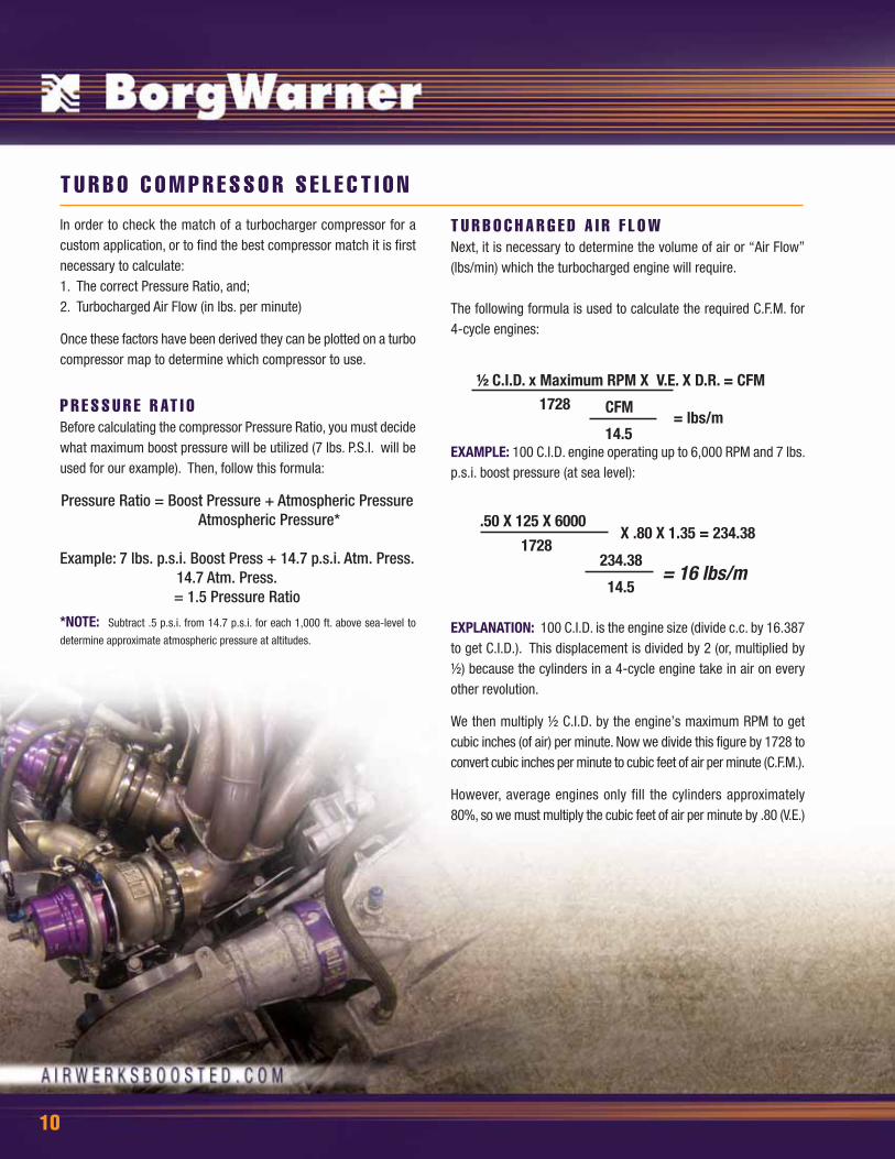
In order to check the match of a turbocharger compressor for acustom application, or to find the best compressor match it is firstnecessary to calculate:1. The correct Pressure Ratio, and;2. Turbocharged Air Flow (in lbs. per minute)
Once these factors have been derived they can be plotted on a turbocompressor map to determine which compressor to use.
P R E S S U R E R AT I O Before calculating the compressor Pressure Ratio, you must decidewhat maximum boost pressure will be utilized (7 lbs. P.S.I. will beused for our example). Then, follow this formula:
*NOTE: Subtract .5 p.s.i. from 14.7 p.s.i. for each 1,000 ft. above sea-level to
determine approximate atmospheric pressure at altitudes.
T U R B O C O M P R E S S O R S E L E C T I O N
T U R B O C H A R G E D A I R F L O WNext, it is necessary to determine the volume of air or “Air Flow”(lbs/min) which the turbocharged engine will require.
The following formula is used to calculate the required C.F.M. for4-cycle engines:
EXAMPLE: 100 C.I.D. engine operating up to 6,000 RPM and 7 lbs.p.s.i. boost pressure (at sea level):
EXPLANATION: 100 C.I.D. is the engine size (divide c.c. by 16.387to get C.I.D.). This displacement is divided by 2 (or, multiplied by½) because the cylinders in a 4-cycle engine take in air on everyother revolution.
We then multiply ½ C.I.D. by the engine’s maximum RPM to getcubic inches (of air) per minute. Now we divide this figure by 1728 toconvert cubic inches per minute to cubic feet of air per minute (C.F.M.).
However, average engines only fill the cylinders approximately80%, so we must multiply the cubic feet of air per minute by .80 (V.E.)
½ C.I.D. x Maximum RPM X V.E. X D.R. = CFM
CFM
14.5= lbs/m
1728
.50 X 125 X 6000 X .80 X 1.35 = 234.38
234.38
14.5= 16 lbs/m
1728
Pressure Ratio = Boost Pressure + Atmospheric PressureAtmospheric Pressure*
Example: 7 lbs. p.s.i. Boost Press + 14.7 p.s.i. Atm. Press. 14.7 Atm. Press.
= 1.5 Pressure Ratio
11
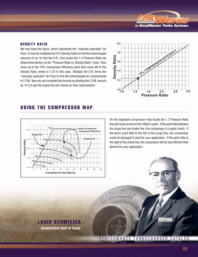
On the displayed compressor map locate the 1.7 Pressure Ratioline and move across to the 16lbs/m point. If the point falls betweenthe surge line and choke line, the compressor is a good match. Ifthe lbs/m point falls to the left of the surge line, the compressorcould be damaged if used for your application. If the point falls tothe right of the choke line, the compressor will be less efficient thandesired for your application.
D E N S I T Y R AT I OWe now have the figure, which represents the “naturally aspirated” AirFlow. It must be multiplied by D.R. (Density Ratio) to find the turbochargedvolumes of air. To find the D.R., first locate the 1.5 Pressure Ratio (asdetermined earlier) on the “Pressure Ratio vs. Density Ratio” chart. Nowmove up to the 70% Compressor Efficiency point then move left to theDensity Ratio, which is 1.25 in this case. Multiply the D.R. times the“naturally aspirated” Air Flow to find the turbocharged air requirementsin C.F.M. Now we can complete the formula by dividing the C.F.M. amountby 14.5 to get the engine lbs per minute air flow requirements.
U S I N G T H E C O M P R E S S O R M A P
L O U I S S C H W I T Z E R-Automotive Hall of Fame

12
Turbo Comp. Wheel Comp. Wheel Comp. Wheel Turbine Turbine Wheel Turbine Wheel Turbine Cartridge ServicePart Number O.D Inducer Dia. Inducer Dia. (mm) Wheel OD Exducer Exducer (mm) A/R Assembly Kit
315641 1.91 1.35 34 1.85 1.58 40 .70 315329 318374314466 1.91 1.35 34 1.85 1.58 40 .61 313275 318374315920 1.91 1.35 34 1.85 1.58 40 .57 313275 318374313377 2.08 1.55 39 2.08 1.8 46 .61 318374
S1BCOMPRESSOR MAP TURBO FRAME DIMENSIONS
13
Turbo Comp. Wheel Comp. Wheel Comp. Wheel Turbine Turbine Wheel Turbine Wheel Turbine Cartridge ServicePart Number O.D Inducer Dia. Inducer Dia. (mm) Wheel OD Exducer Exducer (mm) A/R Assembly Kit
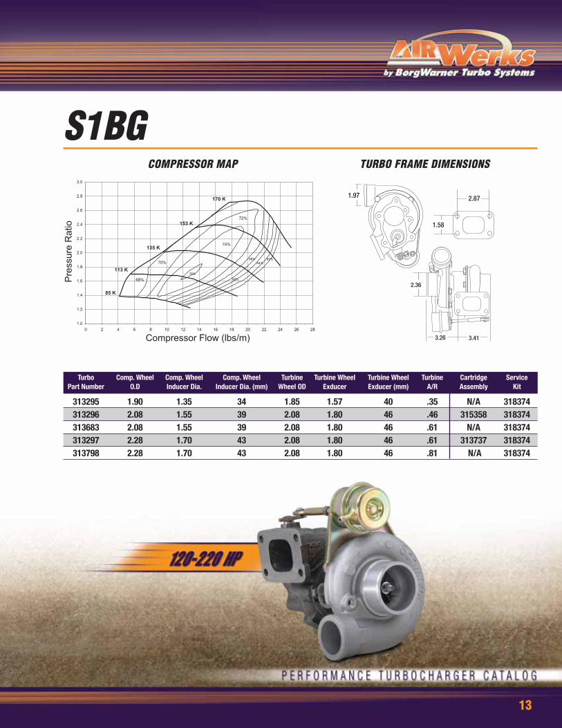
313295 1.90 1.35 34 1.85 1.57 40 .35 N/A 318374313296 2.08 1.55 39 2.08 1.80 46 .46 315358 318374313683 2.08 1.55 39 2.08 1.80 46 .61 N/A 318374 313297 2.28 1.70 43 2.08 1.80 46 .61 313737 318374313798 2.28 1.70 43 2.08 1.80 46 .81 N/A 318374
S1BGCOMPRESSOR MAP TURBO FRAME DIMENSIONS
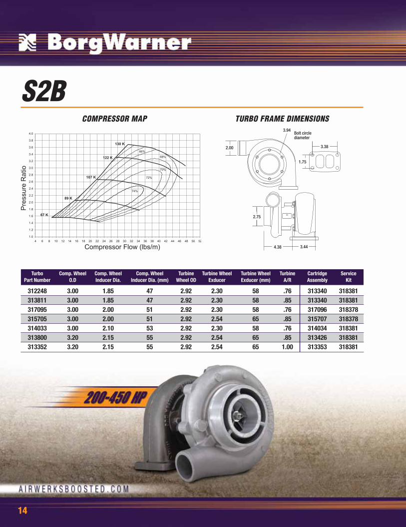
S2BCOMPRESSOR MAP TURBO FRAME DIMENSIONS
14
Turbo Comp. Wheel Comp. Wheel Comp. Wheel Turbine Turbine Wheel Turbine Wheel Turbine Cartridge ServicePart Number O.D Inducer Dia. Inducer Dia. (mm) Wheel OD Exducer Exducer (mm) A/R Assembly Kit
312248 3.00 1.85 47 2.92 2.30 58 .76 313340 318381313811 3.00 1.85 47 2.92 2.30 58 .85 313340 318381317095 3.00 2.00 51 2.92 2.30 58 .76 317096 318378315705 3.00 2.00 51 2.92 2.54 65 .85 315707 318378314033 3.00 2.10 53 2.92 2.30 58 .76 314034 318381313800 3.20 2.15 55 2.92 2.54 65 .85 313426 318381313352 3.20 2.15 55 2.92 2.54 65 1.00 313353 318381

S200COMPRESSOR MAP TURBO FRAME DIMENSIONS
15
Turbo Comp. Wheel Comp. Wheel Comp. Wheel Turbine Turbine Wheel Turbine Wheel Turbine Cartridge ServicePart Number O.D Inducer Dia. Inducer Dia. (mm) Wheel OD Exducer Exducer (mm) A/R Assembly Kit
317222 3.14 2.20 56 2.92 2.54 65 .85 316999 318382317246 3.14 2.20 56 2.92 2.54 65 .76 316999 318382

16
S200SXCOMPRESSOR MAP TURBO FRAME DIMENSIONS
Turbo Comp. Wheel Comp. Wheel Comp. Wheel Turbine Turbine Wheel Turbine Wheel Turbine Cartridge ServicePart Number O.D Inducer Dia. Inducer Dia. (mm) Wheel OD Exducer Exducer (mm) A/R Assembly Kit
177258 2.74 1.81 46 2.74 2.42 61 .83 176639 318383177267 2.74 1.95 50 2.74 2.42 61 1.09 176642 318383177257 2.74 1.10 51 2.74 2.42 61 .83 176638 318383177268 3.00 2.19 56 2.74 2.42 61 1.22 176637 318383
Part Number A/R
177193 1.00177192 1.15177194 1.22
TURBINE HOUSING

17
S300SX3COMPRESSOR MAP TURBO FRAME DIMENSIONS
Turbo Comp. Wheel Comp. Wheel Comp. Wheel Turbine Turbine Wheel Turbine Wheel Turbine Cartridge ServicePart Number O.D Inducer Dia. Inducer Dia. (mm) Wheel OD Exducer Exducer (mm) A/R Assembly Kit
177281 3.60 2.60 66 3.14 2.89 73 .88 176634 318393177275 3.60 2.60 66 3.14 2.89 73 .91 176646 318393177272 3.29 2.36 60 3.00 2.66 68 .91 176635 318393
TURBINE HOUSINGPart
Number A/R
177211 0.88177208 0.91177209 1.00 (177272 Only)177210 0.88 (177272 Only)

18
S300SX3COMPRESSOR MAP TURBO FRAME DIMENSIONS
Turbo Comp. Wheel Comp. Wheel Comp. Wheel Turbine Turbine Wheel Turbine Wheel Turbine Cartridge ServicePart Number O.D Inducer Dia. Inducer Dia. (mm) Wheel OD Exducer Exducer (mm) A/R Assembly Kit
177280 3.29 2.36 60 3.00 2.66 68 .88 171901 318393177283 3.44 2.48 63 3.00 2.66 68 .88 176648 318393177284 3.60 2.60 66 3.14 2.89 73 .91 176650 318393
Part Number A/R
177207 0.91 (177280 & 283 Only)177209 1.00 (177280 & 283 Only)177211 0.88 (177284 Only)
TURBINE HOUSING
19
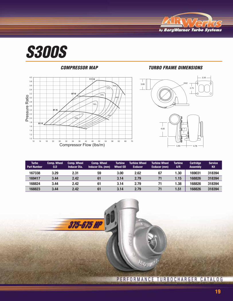
S300SCOMPRESSOR MAP TURBO FRAME DIMENSIONS
Turbo Comp. Wheel Comp. Wheel Comp. Wheel Turbine Turbine Wheel Turbine Wheel Turbine Cartridge ServicePart Number O.D Inducer Dia. Inducer Dia. (mm) Wheel OD Exducer Exducer (mm) A/R Assembly Kit
167338 3.29 2.31 59 3.00 2.62 67 1.30 169031 318394169417 3.44 2.42 61 3.14 2.79 71 1.15 168826 318394168824 3.44 2.42 61 3.14 2.79 71 1.38 168826 318394168823 3.44 2.42 61 3.14 2.79 71 1.51 168826 318394

20
S300GCOMPRESSOR MAP TURBO FRAME DIMENSIONS
DODGE 5.9 ENGINE PERFORMANCE TURBO UPGRADE CHART
1994 Auto 1601994 Manual 1751994 One Ton Truck 2401995 Auto 1601995 Manual 1751996 Auto 1801996 Manual 2151996 California Emission 1801997 Auto 1801997 Manual 2151997 California Emission 1801998 12 Valve Auto 1801998 12 Valve Manual 2151998 12 Calif Emission 180
1998.5 12 Valve Auto & Manual 2151999 Auto 2151999 Manual 2302000 Auto 2152000 Manual 2302001 Auto 2352001 Manual 2452002 Auto 2352002 Manual 245
BorgWarner S300G Upgrade Turbo for Cummins 5.9 Engines
174430 S300G
174430 S300G
174430 S300G
174430 S300G
174430 S300G
174430 S300G
174430 S300G
174430 S300G
174430 S300G
174430 S300G
BW TS TurboModel Transmission Stock Turbo Mfr. ModelYear Type Horsepower Part Number Number

21
About S400SXAirWerks involvement in the sport compact arena created aBorgWarner first… a purpose built, engineered for high performance,production turbocharger.
The formal S400SX turbo program came to life in 2004 as a projectthat teamed BorgWarner with GM Racing. The objective of the AirWerksprogram was to help create reliable and consistent boost for GM’s ProFWD sport compact race cars. After several meetings with the GM Racingteam, the basic design and performance targets were established.
The S400SX turbos were constructed under the supervision of theBorgWarner Turbo and Emissions Systems Aftermarket productdevelopment team and select members of the North AmericanTechnical-Sport Center Headquarters. The units were built as prototypes
and the suffix “X” was added to the standard model nomenclature tohelp distinguish this unique motorsport component from the standardcommercial product assembled at the same location..
By the end of 2005 race season, the S400SX had begun to create apresence in the sport compact arena. The GM Racing Cobalt was thefirst and only front-wheel-drive/four-cylinder to surpass 200mph inthe quarter mile. Moreover, it ran the quickest and fastest FWD passever with 7.292s @ 201.61. The very same year, Brent Rau pushedhis Mitsubishi Eclipse to a new ET record of 6.976 and established anew Pro Outlaw RWD MPH record of 198.29. The introduction of theS400SX with these initial race teams proved to form lastingrelationships which are still honored today.
S400SX
22
TURBINE HOUSINGPart
Number A/R
176809 0.90176810 1.00176812 1.25
COMPRESSOR COVERPart
Number
177212 (177248 Only)177352 w/Attenuator
(177248 Only)
177354 w/Attenuator (177101 Only)
4.21
2.75
4.622
3.25
Compressor Flow (lbs/m)
Pre
ssur
e R
atio
S400SX3COMPRESSOR MAP TURBO FRAME DIMENSIONS
5.00
5.82 5.34
Turbo Comp. Wheel Comp. Wheel Comp. Wheel Turbine Turbine Wheel Turbine Wheel Turbine Cartridge ServicePart Number O.D Inducer Dia. Inducer Dia. (mm) Wheel OD Exducer Exducer (mm) A/R Assembly Kit
177248 3.94 2.80 71 3.29 2.93 74 1.10 176807 318396177101 3.94 2.94 75 3.29 2.93 74 1.10 176807 318396

23
4.21
2.75
4.43
5.75
Compressor Flow (lbs/m)
Pre
ssur
e R
atio
S400SX4COMPRESSOR MAP TURBO FRAME DIMENSIONS
5.345.55
5.00
Turbo Comp. Wheel Comp. Wheel Comp. Wheel Turbine Turbine Wheel Turbine Wheel Turbine Cartridge ServicePart Number O.D Inducer Dia. Inducer Dia. (mm) Wheel OD Exducer Exducer (mm) A/R Assembly Kit
171701 3.94 2.80 71 3.77 3.47 88 1.32 171699 176391171702 3.94 2.94 75 3.77 3.47 88 1.32 171703 176391176806 3.94 2.94 75 3.29 2.93 74 1.10 176807 176391
TURBINE HOUSINGPart
Number A/R
176809 0.90176810 1.00176812 1.25
(176806 Only)

24
3.00
2.75
5.754.44
Compressor Flow (lbs/m)
Pres
sure
Rat
io
S400SX4COMPRESSOR MAP TURBO FRAME DIMENSIONS
5.50
6.39 5.01
Turbo Comp. Wheel Comp. Wheel Comp. Wheel Turbine Turbine Wheel Turbine Wheel Turbine Cartridge ServicePart Number O.D Inducer Dia. Inducer Dia. (mm) Wheel OD Exducer Exducer (mm) A/R Assembly Kit
177287 4.32 3.16 80 3.77 3.47 88 1.32 176654 176391
25
3.58
2.75
4.44
5.15
Compressor Flow (lbs/m)
Pre
ssur
e R
atio
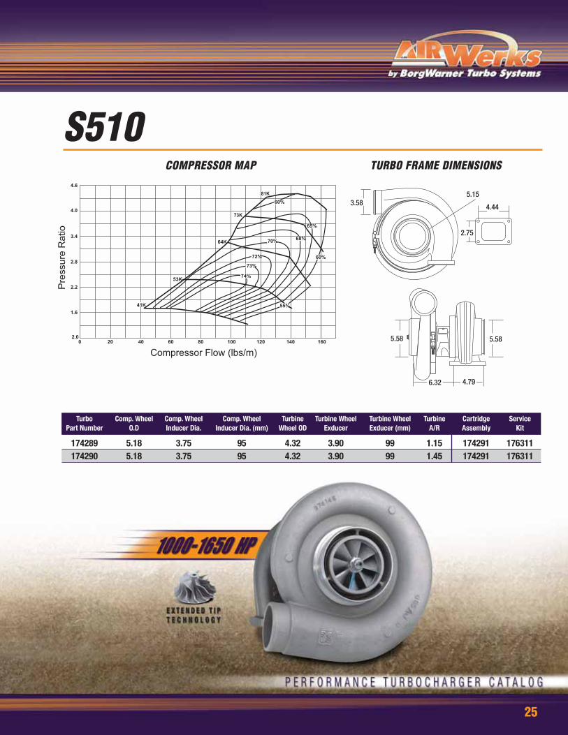
S510COMPRESSOR MAP TURBO FRAME DIMENSIONS
6.32
5.58 5.58
4.79
Turbo Comp. Wheel Comp. Wheel Comp. Wheel Turbine Turbine Wheel Turbine Wheel Turbine Cartridge ServicePart Number O.D Inducer Dia. Inducer Dia. (mm) Wheel OD Exducer Exducer (mm) A/R Assembly Kit
174289 5.18 3.75 95 4.32 3.90 99 1.15 174291 176311174290 5.18 3.75 95 4.32 3.90 99 1.45 174291 176311

26
BV50TURBO COMPARISON TURBO FRAME DIMENSIONS
Manufacturer Vehicle Reference No. Year HP Litres Service Turbo No. Model SPec Remarks
Porsche 911 Turbo (997) 997.123.014.72 2005 480 3.6 5304 988 0060 BV50-2277 Stock Turbo (Right Side)Porsche 911 Turbo (997) 997.123.013.72 2005 480 3.6 5304 988 0061 BV50-2277 Stock Turbo (Left Side)Porsche 911 GT2 (997) 997.123.078.71 2007 530 3.6 5304 988 0080 BV50-2280 Upgrade Turbo (Right Side)Porsche 911 GT2 (997) 997.123.014.70 2007 530 3.6 5304 988 0081 BV50-2280 Upgrade Turbo (Left Side)
BorgWarner was the first manufacturer in the world to offer VTG turbochargers for gasoline engines in mass production. BV turbos employ materials and
designs that are optimally tuned to the high thermal loads in gasoline engines. BorgWarner has developed a robubst VTG mechanism that works reliably even
in the toughest of conditions and also employ a CFD-Optimized vane design that provides excellent efficiency.

27
2.082.95
3.41
Compressor Flow (lbs/m)
Pre
ssur
e R
atio
K03-2072COMPRESSOR MAP TURBO FRAME DIMENSIONS
1.73
2.957.43
Turbo Comp. Wheel Comp. Wheel Comp. Wheel Turbine Turbine Wheel Turbine Wheel Turbine Cartridge ServicePart Number O.D Inducer Dia. Inducer Dia. (mm) Wheel OD Exducer Exducer (mm) A/R Assembly Kit
5303 988 0029 1.81 1.32 34 1.78 1.57 40 52 cm 5303 710 0511 5304 711 0000

28
2.082.95
3.41
Compressor Flow (lbs/m)
Pre
ssur
e R
atio
K03-2075COMPRESSOR MAP TURBO FRAME DIMENSIONS
1.73
2.957.43
Turbo Comp. Wheel Comp. Wheel Comp. Wheel Turbine Turbine Wheel Turbine Wheel Turbine Cartridge ServicePart Number O.D Inducer Dia. Inducer Dia. (mm) Wheel OD Exducer Exducer (mm) A/R Assembly Kit
5303 988 0073 2.00 1.50 38 1.81 1.65 42 52cm 5303 710 0521

29
Audi Upgrade
Compressor Flow (lbs/m)
Pre
ssur
e R
atio
K04-2075COMPRESSOR MAP TURBO FRAME DIMENSIONS
Application Model Engine RatedModel Year Spec HP
Audi A3 1.8T, 96-01 1.8 liter 220VW Beetle 5-Valve,
Transverse
Golf 1996 1.8 liter 2205-Valve,
Transverse
Turbo Comp. Wheel Comp. Wheel Comp. Wheel Turbine Turbine Wheel Turbine Wheel Turbine Cartridge ServicePart Number O.D Inducer Dia. Inducer Dia. (mm) Wheel OD Exducer Exducer (mm) A/R Assembly Kit
5304 950 0001 2.00 1.50 38 1.81 1.65 42 5²cm 5303 711 0000
30
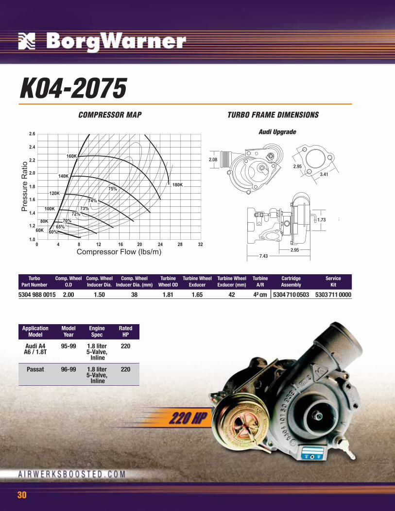
2.082.95
3.41
Audi Upgrade
Compressor Flow (lbs/m)
Pre
ssur
e R
atio
K04-2075COMPRESSOR MAP TURBO FRAME DIMENSIONS
1.73
2.957.43
2
Turbo Comp. Wheel Comp. Wheel Comp. Wheel Turbine Turbine Wheel Turbine Wheel Turbine Cartridge ServicePart Number O.D Inducer Dia. Inducer Dia. (mm) Wheel OD Exducer Exducer (mm) A/R Assembly Kit
5304 988 0015 2.00 1.50 38 1.81 1.65 42 4² cm 5304 710 0503 5303 711 0000
Application Model Engine RatedModel Year Spec HP
Audi A4 95-99 1.8 liter 220A6 / 1.8T 5-Valve,
Inline
Passat 96-99 1.8 liter 2205-Valve,
Inline

31
2.134.65
2.40
1.79
Bolt circle diameter
Compressor Flow (lbs/m)
Pre
ssur
e R
atio
K04-2275COMPRESSOR MAP TURBO FRAME DIMENSIONS
4.147.22
2.01
Turbo Comp. Wheel Comp. Wheel Comp. Wheel Turbine Turbine Wheel Turbine Wheel Turbine Cartridge ServicePart Number O.D Inducer Dia. Inducer Dia. (mm) Wheel OD Exducer Exducer (mm) A/R Assembly Kit
5304 988 0023 2.20 1.65 42 1.97 1.65 42 5² cm 5304 710 0507 5303 711 0000

32
1.89
4.33
2.94
2.42
Bolt circle diameter
Compressor Flow (lbs/m)
Pre
ssur
e R
atio
K16-2467COMPRESSOR MAP TURBO FRAME DIMENSIONS
2.28
4.147.22
Turbo Comp. Wheel Comp. Wheel Comp. Wheel Turbine Turbine Wheel Turbine Wheel Turbine Cartridge ServicePart Number O.D Inducer Dia. Inducer Dia. (mm) Wheel OD Exducer Exducer (mm) A/R Assembly Kit
5316 988 6717 2.39 1.60 41 2.17 1.81 46 7²cm

33
3.62
3.00
1.50
Bolt circle diameter
2.00
Compressor Flow (lbs/m)
Pre
ssur
e R
atio
K26COMPRESSOR MAP TURBO FRAME DIMENSIONS
2.00
2.634.21
Turbo Comp. Wheel Comp. Wheel Comp. Wheel Turbine Turbine Wheel Turbine Wheel Turbine Cartridge ServicePart Number O.D Inducer Dia. Inducer Dia. (mm) Wheel OD Exducer Exducer (mm) A/R Assembly Kit
5326-988-6720 2.60 1.73 44 2.52 1.88 48 6²cm 5326 710 0507 5326 711 00285326-988-7042 2.60 1.80 46 2.52 2.17 55 8²cm 5326 710 0522 5326 711 0015

34
2.00
3.81
3.37
1.80
Bolt circle diameter
Compressor Flow (lbs/m)
Pre
ssur
e R
atio
K27-3072COMPRESSOR MAP TURBO FRAME DIMENSIONS
2.75
7.34
Turbo Comp. Wheel Comp. Wheel Comp. Wheel Turbine Turbine Wheel Turbine Wheel Turbine Cartridge ServicePart Number O.D Inducer Dia. Inducer Dia. (mm) Wheel OD Exducer Exducer (mm) A/R Assembly Kit
5327 988 7200 3.00 2.16 55 2.75 2.31 59 11²cm 5327 710 0518 5326 711 0040

35
K29-3775COMPRESSOR MAP TURBO FRAME DIMENSIONS
Turbo Comp. Wheel Comp. Wheel Comp. Wheel Turbine Turbine Wheel Turbine Wheel Turbine Cartridge ServicePart Number O.D Inducer Dia. Inducer Dia. (mm) Wheel OD Exducer Exducer (mm) A/R Assembly Kit
5329 988 7115 3.70 2.79 70.93 3.23 2.80 71.00 17²cm N/A 5331 711 0005
Utilizing Forged Milled Compressor Wheel (FMW) Technology
• Stronger Than Cast Wheels• Higher Pressure Ratio• Resists High Cycle Fatigue

36
The history of turbocharging is almost as old as that of the internal combustionengine. As early as 1885 and 1896, Gottlieb Daimler and Rudolf Diesel investigatedincreasing the power output and reducing the fuel consumption of their enginesby precompressing the combustion air.
In 1925, the Swiss engineer Alfred Büchi was the first to be successful with theexhaust gas turbocharging and achieved a power increase of more than 40%. This was the beginning of the gradual introduction of turbocharging into theautomotive industry.
The first turbocharger applications were limited to very large engines, e.g. marineengines. In the automotive engine industry, turbocharging started with truckengines. In 1938, the “Swiss Machine Works Saurer” built the first turbochargedengine for trucks.
The Chevrolet Corvair Monza and the Oldsmobile Jetfire, the first turbo-poweredpassenger cars, made their US market debut in 1962/63. Despite the maximumtechnical outlay, however, their poor reliability caused them to disappear from themarket quickly.
After the first oil crisis in 1973, turbocharging became more acceptable incommercial diesel applications. Until then, the high investment costs ofturbocharging were offset only by fuel cost savings, which were minimal.Increasingly stringent emission regulations in the late 80s resulted in an increasein the number of turbocharged truck engines, so that today, virtually every truckengine is turbocharged.
In the 70s, with the turbocharger’s entry into motor sports, especially into Formula1 racing, the turbocharged passenger care engine became very popular. The word“turbo” became quite fashionable. At that time, almost every automobilemanufacturer offered at least one top model equipped with a turbocharged gasolineengine. However, this phenomenon disappeared after a few years because althoughthe turbocharged gasoline engine was more powerful, it was not economical.Furthermore, the “turbo-lag”, the delayed response of the turbocharger, was at thetime still relatively large and not accepted by most customers.
The real breakthrough in passenger car turbocharging was achieved in 1978 withthe introduction of the first turbocharged diesel engine in the Mercedes-Benz 300SD, followed by the VW Golf Turbodiesel in1981. By means of the turbocharger, thediesel engine passenger car’s efficiency could be increased, with almost gasolineengine “driveability”, and the emissions significantly reduced.
Today, the turbocharging of gasoline engines is no longer primarily seen from theperformance perspective, but is rather viewed as a means of reducing fuelconsumption and environmental pollution on account of lower carbon dioxideemissions. Nevertheless, some of the 60s and 70s fascination for turbochargingstill exists today. Currently, the primary reason for turbocharging is the use ofexhaust gas energy to reduce fuel consumption and emissions. Therefore,turbochargers contribute considerably to environmental protection and the conservationof energy resources.
Introduction
The development of turbochargers always follows market requirements, and hastherefore reached the same high technical standard as the internal combustionengine. But development is far from being finished. As a result of the continuingdevelopment of exhaust gas turbocharger technology, further improvements to theengine’s operational characteristics with regard to power output, fuel consumptionand emissions can be expected in the future.
As turbochargers have to meet different requirements with regard to map height,map width, efficiency characteristics, moment of inertia of the rotor and conditionsof use, new compressor and turbine types are continually being developed forvarious engine applications. Furthermore, different regional legal emissionregulations lead to different technical solutions.
The compressor and turbine wheels have the greatest influence on theturbocharger’s operational characteristics. These wheels are designed by a meansof computer programs, which allow a three-dimensional calculation of the air andexhaust gas flows. The wheel strength is simultaneously optimized by means ofthe finite-element method (FEM), and durability calculated on the basis of realisticdriving cycles. The resulting solution is represented on CAD programs. On the basisof CAD data, first prototypes are manufactured on numerically controlled 5-axismilling machines,
Despite today’s advanced computer technology and detailed calculation programs,it is testing which finally decides on the quality of the new aerodynamiccomponents. The fine adjustment and checking of results is therefore carried outon the turbocharger test stands. Afterwards, the new components are integratedinto production series turbochargers.
Development
BorgWarner Turbo & Emissions Systems Headquarters - Kirchheimbolanden Germany

37
North American Sales and Technical Center- Arden, North Carolina
The vital components of a turbocharger are the turbine and the compressor. Bothare turbo-machines, which, with the help of modeling laws, can be manufacturedin various sizes with similar characteristics. Thus, by enlarging and reducing, theturbocharger range is established, allowing the optimal turbocharger frame size tobe made available for various engine sizes. However, the transferability to otherframe sizes is restricted, as not all characteristics can be scaled dimensionally.Furthermore, requirements vary in accordance with each engine size, so that it isnot always possible to use the same wheel or housing geometries. The modelsimilarity and modular design principle, however, permit the development ofturbochargers which are individually tailored to every engine. This starts with theselection of the appropriate compressor on the basis of the required boost pressurecharacteristic curve. Ideally, the full-load curve should be such that the compressorefficiency is at its maximum in the main operating range of the engine. The distanceto the surge line should be sufficiently large.
The thermodynamic matching of the turbocharger is implemented by a means ofmass flow and energy balances. The air delivered by the compressor and the fuelfed to the engine constitutes the turbine mass flow rate. In steady-state operation,the turbine and compressor power outputs are identical (free wheel condition). Thematching calculation is iterative, based on compressor and turbine maps. As wellas the most important engine data.
The matching calculation can be very precise when using computer programs forthe calculated engine and turbocharger simulation. Such programs include mass,energy and material balances for all cylinders and the connected pipework. Theturbocharger enters into the calculation in the form of maps. Furthermore, suchprograms include a number of empirical equations to describe inter-relationshipswhich are difficult to express in an analytical way. The computational simulationfor the calculation of complex charging systems with several turbochargers andadditional charger components is of special interest. Computer simulation can onlybe considered as a supplement to testing, as the simulation itself is based on anumber of assumptions.
For vehicle engines, the precision of a simple matching calculation to determinethe appropriate compressor and the matching turbine is usually sufficient. Becausethe turbocharger is constructed in accordance with a modular design, the requiredboost pressure can be reached much quicker during an engine test by changingindividual turbocharger components such as the turbine or compressor housing.
Besides thermodynamic considerations, a constructive adaptation of all connectionsto the engine is necessary to take into account the limited installation possibilitiesin the engine compartment. After selections of the compressor and the turbine andcompletion of the installation drawing, the customer can integrate the turbochargerinto the engine and vehicle drawings by means of the CAD data package.
Matching
The turbocharger has to operate as reliably and for as long as the engine. Thepurchaser of a vehicle expects this from the vehicle manufacturer, and the vehiclemanufacturer from his supplier. Before a turbocharger is released for seriesproduction, it has to undergo a number of tests. This test program includes tests of
individual turbocharger components, tests on the turbocharger test stand and atest on the engine. Some tests from this complex testing program are describedbelow in detail.
Testing
If a compressor or turbine wheel bursts the remaining parts of the wheel must notpenetrate the compressor or turbine housing. To achieve this, the shaft and turbinewheel assembly is accelerated to such a high speed that the respective wheel
bursts. After bursting, the housing’s containment safety is assessed. The burstspeed is typically 50% above the maximum permissible speed.
Containment Test

38
The LCF test is a load test of the compressor or turbine wheel resulting in thecomponent’s destruction. It is used to determine the wheel material load limits. Thecompressor or turbine wheel is installed on an overspeed test stand. The wheel is
accelerated by means of an electric motor until the specified tip speed is reachedand then slowed down. On the basis of results and the component’s S/N curve, theexpected lifetime can be calculated for every load cycle.
Low-cycle Fatigue Test (LCF Test)
During the wastegate test, the load tolerance of the metal components and of thediaphragm is tested. To this end, an actual load in stroke direction and perpendicularto it is simulated on a gas stand. The components have to endure 1.5 million load
cycles without being damaged. This is approximately double the required lifetime inthe real driving cycle.
Wastegate Test
The pulsating gas forces on the turbine affect the rotational movement of the rotor.Through its own residual imbalance and through mechanical vibrations of the engine,it is simulated to vibrate. Large amplitudes may therefore occur within the bearingclearance and lead to instabilities, especially when the lubricating oil pressures areto low and the oil temperatures too high. At worst, this will result in metallic contactand abnormal mechanical wear.
The motion of the rotor is measured and recorded by the contactless transducerslocated in the suction area of the compressor by means of the eddy current method.In all conditions and at all operating points, the rotor amplitudes should not exceed 80% of maximum possible values. The motion of the rotor must not showany instability.
Rotor Dynamic Measurement
This method allows measurement of the dynamic stresses on the turbine bladesduring engine operation at the highest temperatures. High-temperature straininggauges, which are fixed onto the turbine blades at points of maximum stress, areused as transducers. The measured signals are transmitted to the measuringinstruments by means of a small, telemetric system that rotates with the
turbocharger. At specific speeds, the blades can be excited to resonance vibrationsthat can endanger the turbocharger’s operational safety. In order to eliminate the riskof excessive dynamic stressing of the turbine blades, all models are examined withregard to their vibration characteristics and then optimized.
Turbine Blade Vibration Measurement
In actual operating conditions, the lubricating oil must not get into the compressor orinto the turbine. The turbocharger is therefore tested, together with the engine, onan engine test stand at all possible load and speed points.To test the compressor-side piston ring, a negative pressure is gradually generatedat the compressor inlet, as might be produced in service by a dirty air filter. At any
operating point, up to a certain negative pressure, no oil fouling of the compressormust occur.To test the turbine-side piston ring, a positive pressure is gradually built up in theengine’s crankcase, as might occur through a blocked engine breathing system. Heretoo, up to a certain limiting value, no oil leakage should occur.
Piston Ring Leakage Test
The temperature drop in the turbocharger between the gases at the hot turbine sideand at the cold compressor inlet can amount to as much as 1000°C in a distance ofonly a few centimeters. During the engine’s operation, the lubricating oil passingthrough the bearing cools the center housing so that no critical componenttemperatures occur. After the engine has been shut down, especially from high loads,heat can accumulate in the center housing, resulting in coking of the lubricating oil.It is therefore of vital importance to determine the maximum component temperatures
at the critical points, to avoid the formation of lacquer and carbonized oil in theturbine-side bearing area and on the piston ring.After the engine has been shut down at the full-load operating point, theturbocharger’s heat build-up is measured. After a specified number of cycles, theturbocharger components are inspected. Only when maximum permissible componenttemperatures are not exceeded and the carbonized oil quantities around the bearingare found to be low, is this test considered passed.
Start-Stop Test
The checking of all components and the determination of the rates of wear areincluded in the cycle test. In this test, the turbocharger is run on the engine for several
hundred hours at varying load points. The rates of wear are determined by the detailedmeasurements of the individual components, before and after the test.
Cyclic Endurance Test

39
Limited Warranty: BorgWarner Turbo Systems Inc. (“BWTS”)
warrants that its goods or merchandise will be free from defects
in material and workmanship for its intended use and service. This
Warranty shall extend for a period of twelve (12) months from the
date of purchase by end user. BWTS will repair or provide a
replacement product, at BWTS’s sole option, for any defective part.
Replaced parts will be warranted in time only through the
remaining period of this Warranty. BWTS shall not be obligated to
repair or replace any defective part unless it receives notice, in
writing, within 14 days of discovery of a defect. Any action for
breach of warranty, contract or otherwise, shall be barred unless
BWTS is provided with notice as provided herein. Specifically
excluded from this Warranty are design defects or defects or
damage caused by improper installation, misuse, neglect, improper
maintenance, handling or operation of the product or unauthorized
repair or alterations or externally induced physical damage.
Further, this Warranty shall not apply if any person attempts to
repair or replace the defective part without BWTS’s written
authorization. Any auxiliary equipment sold hereunder and not
manufactured by BWTS carries only such warranty as given by the
manufacturer thereof and which is hereby assigned without
recourse to BWTS. No warranty is made for any other claims or
special, indirect or consequential damages (including but not
limited to component removal or installation, equipment down
time, prospective profits or other economic losses) because of any
defect deemed warrantable by BWTS.
THIS IS BWTS’S SOLE WARRANTY AND IS IN LIEU OF ALL OTHER
WARRANTIES, EXPRESS OR IMPLIED, INCLUDING, WITHOUT LIMITATION,
IMPLIED WARRANTY OF MERCHANTABILITY, OR FITNESS FOR A
PARTICULAR PURPOSE. No representative or distributor of BWTS
has the authority to change or alter this Warranty. This Warranty
may only be modified by an agreement signed by an authorized
officer of BWTS.
Any claim made under this limited warranty must be presented to
BWTS, with valid proof of date of purchase by end-user. All
merchandise or goods shipped to BWTS, for warranty
consideration, must be shipped prepaid - freight collect shipments
will be refused.
NO WARRANTY ON COMPETITION APPLICATIONS OR APPLICATIONS
NOT APPROVED IN WRITING BY BORGWARNER TURBO SYSTEMS.
Warranty
BorgWarner Turbo Systems Worldwide Headquarters GmbH Marnheimer Strasse 88
D-67292 Kirchheimbolanden, Germany
North American Sales and Technical Center1849 Brevard Road
Arden, NC [email protected] (for wholesale inquires only)
airwerksboosted.comPPC0110-B