Embed Size (px)
Citation preview
Fiabilitate si Durabilitate - Fiability & Durability No 1/ 2017 Editura “Academica Brâncuşi” , Târgu Jiu, ISSN 1844 – 640X
191
ABOUT FEATURES OF SIMULATION MODULE
IN SOLIDWORKS
prof.PhD.eng. Cătălin IANCU
Engineering and Sustainable Development Faculty,”C-tin Brâncuşi” Univ. of Tg-Jiu,
Abstract: In this paper are presented the additional features and analysis steps of Simulation module in
SolidWorks, for conducting a more detailed study of designed parts. There are presented the module
features, the settings that have to be done for such analysis and the results shown after analysis.
Keywords: SolidWorks, Simulation, FEM analysis.
1. INTRODUCTION
As presented in [1], SolidWorks SimulationExpress Module “offers an easy-to-use
first pass stress analysis tool for SolidWorks users. SimulationXpress can help you reduce
cost and time-to-market by testing your designs on the computer instead of expensive and
time-consuming field tests”. As described in [2], without using a simulation tool, the design
process is a time-consuming product development cycles. Typically must be taken following
steps: build the model in SolidWorks CAD system, prototype the design, test the prototype in
the field, evaluate the results of the field tests and modify the design based on the field test
results. This process can continue until a satisfactory solution is reached. By using
SimulationExpress/Simulation the same task can be accomplish, reducing costs, by testing the
model using the computer rather than field tests, reducing time to market by reducing the
number of product development cycles and optimize the designs by simulating concepts and
scenarios before making final decisions [2].
Two modules are available for SolidWorks: SimulationXpress that handles part
documents (only solid bodies), included in the core software, and Simulation that handles
parts and assemblies too, which is available as a separate product, including configuration
support and expanded options. SolidWorks Simulation is a design analysis system fully
integrated with SolidWorks. SolidWorks Simulation “provides simulation solutions for linear
and nonlinear static, frequency, buckling, thermal, fatigue, pressure vessel, drop test, linear
and nonlinear dynamic, and optimization analyses” [1].
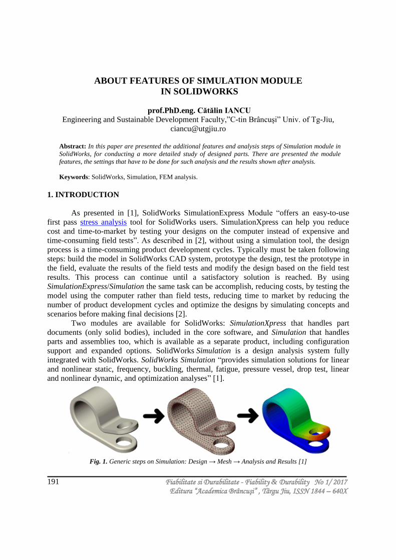
Fig. 1. Generic steps on Simulation: Design → Mesh → Analysis and Results [1]
Fiabilitate si Durabilitate - Fiability & Durability No 1/ 2017 Editura “Academica Brâncuşi” , Târgu Jiu, ISSN 1844 – 640X
192
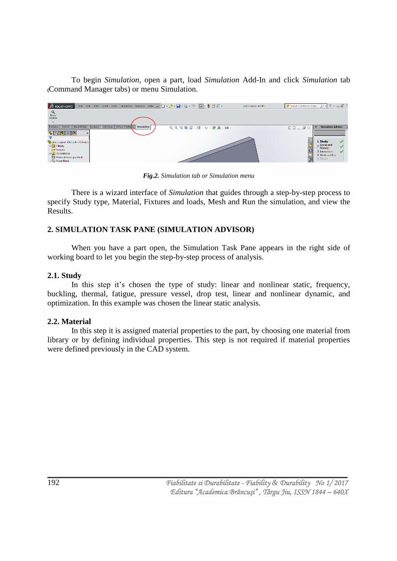
To begin Simulation, open a part, load Simulation Add-In and click Simulation tab
(Command Manager tabs) or menu Simulation.
Fig.2. Simulation tab or Simulation menu
There is a wizard interface of Simulation that guides through a step-by-step process to
specify Study type, Material, Fixtures and loads, Mesh and Run the simulation, and view the
Results.
2. SIMULATION TASK PANE (SIMULATION ADVISOR)
When you have a part open, the Simulation Task Pane appears in the right side of
working board to let you begin the step-by-step process of analysis.
2.1. Study
In this step it’s chosen the type of study: linear and nonlinear static, frequency,
buckling, thermal, fatigue, pressure vessel, drop test, linear and nonlinear dynamic, and
optimization. In this example was chosen the linear static analysis.
2.2. Material
In this step it is assigned material properties to the part, by choosing one material from
library or by defining individual properties. This step is not required if material properties
were defined previously in the CAD system.

Fiabilitate si Durabilitate - Fiability & Durability No 1/ 2017 Editura “Academica Brâncuşi” , Târgu Jiu, ISSN 1844 – 640X
193
Fig. 3. Choosing material for the part
2.3. Interactions
In this step it’s applied fixtures to faces or edges of the part, as shown in figure 4, and
loads like forces or pressures, or both to faces of the part.
Fiabilitate si Durabilitate - Fiability & Durability No 1/ 2017 Editura “Academica Brâncuşi” , Târgu Jiu, ISSN 1844 – 640X
194
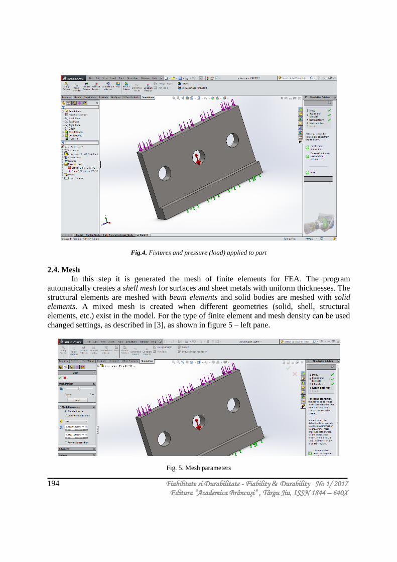
Fig.4. Fixtures and pressure (load) applied to part
2.4. Mesh
In this step it is generated the mesh of finite elements for FEA. The program
automatically creates a shell mesh for surfaces and sheet metals with uniform thicknesses. The
structural elements are meshed with beam elements and solid bodies are meshed with solid
elements. A mixed mesh is created when different geometries (solid, shell, structural
elements, etc.) exist in the model. For the type of finite element and mesh density can be used
changed settings, as described in [3], as shown in figure 5 – left pane.
Fig. 5. Mesh parameters
Fiabilitate si Durabilitate - Fiability & Durability No 1/ 2017 Editura “Academica Brâncuşi” , Târgu Jiu, ISSN 1844 – 640X
195
2.5. Run
Uses the default settings or changed settings for the simulation and then run analysis.
Practically it’s done a static analysis by FEM of studied part, with default or changed settings.
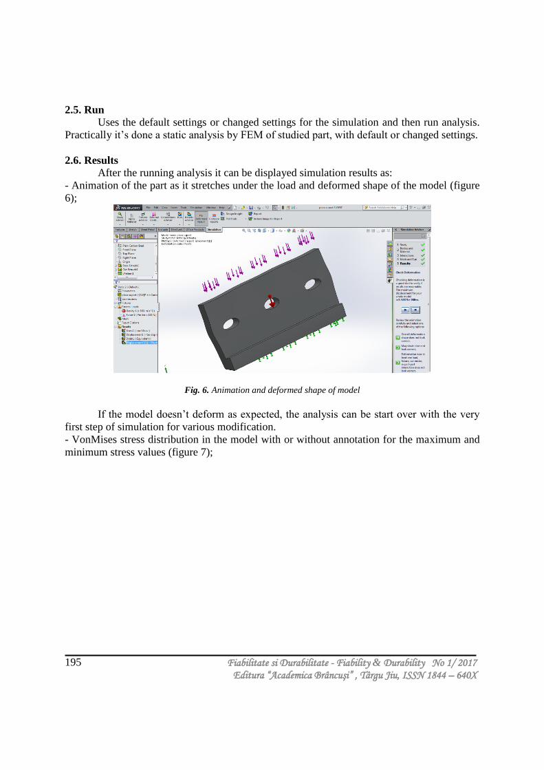
2.6. Results
After the running analysis it can be displayed simulation results as:
- Animation of the part as it stretches under the load and deformed shape of the model (figure
6);
Fig. 6. Animation and deformed shape of model
If the model doesn’t deform as expected, the analysis can be start over with the very
first step of simulation for various modification.
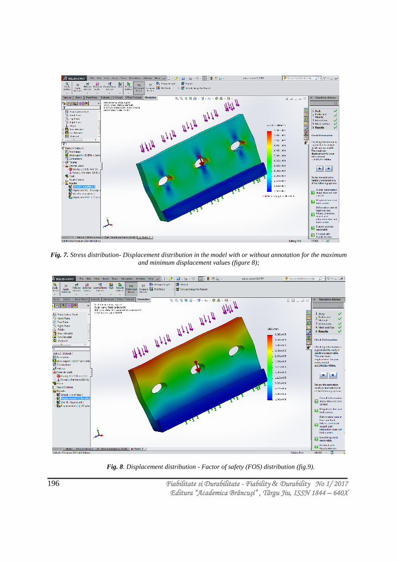
- VonMises stress distribution in the model with or without annotation for the maximum and
minimum stress values (figure 7);
Fiabilitate si Durabilitate - Fiability & Durability No 1/ 2017 Editura “Academica Brâncuşi” , Târgu Jiu, ISSN 1844 – 640X
196
Fig. 7. Stress distribution- Displacement distribution in the model with or without annotation for the maximum
and minimum displacement values (figure 8);
Fig. 8. Displacement distribution - Factor of safety (FOS) distribution (fig.9).
Fiabilitate si Durabilitate - Fiability & Durability No 1/ 2017 Editura “Academica Brâncuşi” , Târgu Jiu, ISSN 1844 – 640X
197
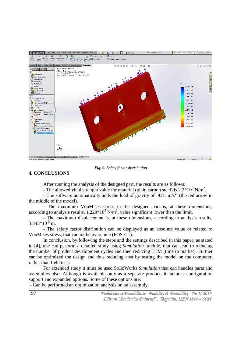
Fig. 9. Safety factor distribution
4. CONCLUSIONS
After running the analysis of the designed part, the results are as follows:
- The allowed yield strenght value for material (plain carbon steel) is 2.2*108 N/m
2.
- The software automatically adds the load of gravity of 9.81 m/s2
(the red arrow in
the middle of the model).
- The maximum VonMises stress in the designed part is, at these dimensions,
according to analysis results, 1.229*105 N/m
2, value significant lower than the limit.
- The maximum displacement is, at these dimensions, according to analysis results,
3.345*10-5
m.
- The safety factor distribution can be displayed as an absolute value or related to
VonMises stress, that cannot be overcome (FOS < 1).
In conclusion, by following the steps and the settings described in this paper, as stated
in [4], one can perform a detailed study using Simulation module, that can lead to reducing
the number of product development cycles and then reducing TTM (time to market). Further
can be optimized the design and thus reducing cost by testing the model on the computer,
rather than field tests.
For extended study it must be used SolidWorks Simulation that can handles parts and
assemblies also. Although is available only as a separate product, it includes configuration
support and expanded options. Some of these options are:
- Can be performed an optimization analysis on an assembly.
Fiabilitate si Durabilitate - Fiability & Durability No 1/ 2017 Editura “Academica Brâncuşi” , Târgu Jiu, ISSN 1844 – 640X
198
- Can be specified up to 20 dimensions as design variables.
- Can be specified up to 60 criteria for the model to satisfy.
- Can maximize or minimize any quantity that can be defined as a sensor.
It is obvious that is very useful, both in terms of time and money saving, leading
indirectly to better sustainability of designed products.
REFERENCES
[1]. SolidWorks user help, Dassault Systèmes SolidWorks Corporation, Waltham, MA, USA,
2014.
[2]. Iancu, C., About SimulationExpress module features, Fiability & Durability Revue, ISSN
1844-640X, 1/2015
[3]. Iancu, C., Dimensional optimization of mechanical press, Ed. MJM, Craiova, Romania,
2002.
[4]. Lombard, M., SolidWorks Bible, Wiley & Sons, USA, 2013