Embed Size (px)
Citation preview

1ABOUT METADATA MODELS
There once was a fellow named CoreyWhose career was not covered in gloryHe had a bad dayWhen he just couldn’t sayMe-ta-da-ta Re-pos-i-TOR-y.
WHAT ARE METADATA?∗
During the 1990s, the concept of data warehouse∗∗ swept the information tech-nology industry. After many years of trying, it appears finally to be possible for acompany to store all of its data in one place for purposes of reporting and analysis.The technology for doing this is still new, and the first attempts have had mixedresults, but the effort has been quite serious.
One of the problems that arose from this effort was the realization that if asenior executive is going to ask a giant database a question it is necessary to knowjust what is in the database and what types of questions to ask. In addition to thedata themselves, therefore, it is necessary to keep data about the data. The termcoined for “data about data” during the 1990s was metadata.
Since then, numerous books and magazine articles have been published on thissubject, but most have focused on why metadata are important and on technologiesand techniques for managing them. What these publications have left out is a clear
∗Ok, it’s true. I studied Latin in high school and have always held that data is the plural form ofthe word datum. I realize that I may be swimming against the current, but, hey! It’s my book!∗∗Key words and phrases, shown in bold italic font, are defined in the glossary at the back of thebook.
1

2 ABOUT METADATA MODELS
description of exactly what the stuff is. After a decade, there is still no simple, cleardescription of metadata in a form that is both comprehensive enough to cover ourindustry and comprehensible enough that it can be used by people. This book isan attempt to produce such a description.
As with all buzzwords, once invented the term metadata has taken on a life ofits own. It is variously described as:
• Any data about the organization’s data resource [Brackett 2000, p. 149].• All physical data and knowledge from inside and outside an organization,
including information about the physical data, technical and business pro-cesses, rules and constraints of the data, and structures of the data used bya corporation [Marco 2000, p. 5].
• The detailed description of instance data. The format and characteristics ofpopulated instance data: instances and values, dependent on the role of themetadata recipient [Tannenbaum 2002, p. 93].
Several significant points come out of these definitions. First, as Mr. Marcopointed out there is a difference between business metadata and technical meta-data. The business user of metadata is interested in definitions and structures ofthe language as terms for the types of information to be retrieved. The technicianis concerned with the physical technologies used to store and manage data. Bothof these points of view are important, and both must be addressed.
Second, the subject is concerned with more than just data. It is, as Mr. Brackettsaid, “any data about an organization’s data resource.” Once you have startedlooking at the structure of an organization’s data, you have to also account for itsactivities, people and organizations, locations, timing and events, and motivation.
Third, as Ms. Tannenbaum pointed out, the “meta” aspect of the question isa matter of point of view. There is metadata relative to the data collected by thebusiness. There is also meta-metadata, which is used to understand and managethe metadata.∗
∗While delivering a lecture on cosmology one day, Sir Arthur Eddington gave a brief overview ofthe early theories of the universe. Among others, he mentioned the American Indian belief that theworld rested on the back of a giant turtle, adding that it was not a particularly useful model as it failedto explain what the turtle itself was resting on. Following the lecture, Eddington was approached by

WHAT ARE METADATA? 3
This Book(Meta-
metadata)
Objects:“Entity Class”“Attribute”
Table:“CHECKING_ACCOUNT”Columns:“Account_number”“Monthly_charge”
Program module:ATM ControllerLanguage:Java
ATM Controller:Java code
Julia Roberts Wall Street branch Checking account#09743569
ATM Withdrawal
Entity class:“Customer”Attributes:“Name”“Birthdate”
Customer Name:“Julia Roberts”CustomerBirthdate:“10/28/67”
Branch Address:“111 Wall Street”Branch Manager:“Sam Sneed”
CHECKING_ACCOUNT.Account_number:= “09743569”CHECKING_ACCOUNT.Montly_charge:“$4.50”
Entity class:“Branch”“Employee”Attributes:“Employee.Address”“Employee.Name”Role:“Each branch mustbe managed byexactly oneEmployee”
Objects:“Entity Class”“Attribute”“Role”
Objects:“Table”“Column”
Objects:“Programmodule”“Language”
Data abouta database(a datamodel)
Elements ofmetadata(metadatamodel)
Data aboutreal-worldthings (a database)
Real-worldthings
DataManagement
(Metadata)
IT Operations(Instance
Data)
Fig. 1–1: Data and metadata.
This last point is illustrated in Figure 1–1. Here, the bottom row shows exam-ples of things in the world that are often described in information systems. “JuliaRoberts” is a real human being. The “Wall Street branch” of a bank is a physicalplace were business is performed. Checking account “09743569” is a particularaccount held in that bank by a particular customer (Julia Roberts, for example).The customer of that account may then perform an actual “ATM Withdrawal” ata specific time.
The next row up shows, in the first three columns, the data that might describethose three things: (1) A Customer has the name “Julia Roberts” and the “Birth-date” of “10/28/67”. (2) A Branch has the address “111 Wall Street” and a manager,“Sam Sneed”. (3) The checking account has an account number “09743569”and a monthly charge, “$4.50”. In the fourth column, the first row from the
an elderly lady. “You are very clever, young man, very clever,” she forcefully declared, “but thereis something you do not understand about Indian cosmology: it’s turtles all the way down!”

4 ABOUT METADATA MODELS
bottom shows that a particular program, called here “Java code”, is responsiblefor a “Withdrawal Transaction”. These are the things that would concern a per-son managing data for a banking business. Note that each of the terms wasdescribed as to what it was: customer name, branch manager, account number, andso forth.
The third row from the bottom collects those descriptors and labels them inturn. This is to create what we in the data administration world call the metadata.There are two components to these labels. First are the names of the thingsof significance being described by the business data, such as the entity classes“Customer” and “Branch”. Second, each of these is in turn described by attributes,such as “Name”, “Address”, and “Birthdate”. We also discover, in the case ofthe bank branch, that there is really an additional entity class, “Manager”, andthat it is related to “Branch”. (“Each Branch must be managed by exactly oneEmployee.”)
In the checking account column, we see that a checking account is actuallythe subject of a table in a database. The table is called “CHECKING_ACCOUNT”and has columns “Account_number” and “Monthly_charge”. The ATM programdescribed in the second row simply as “Java code” is actually a program modulewith the name “ATM Controller” written in the language “Java”. As we can see,the metadata row itself encompasses several different types of objects (“Entityclass”, “Attribute”, “Table”, “Column”, “Program module”, and “Language”).The assignment of this book, represented by the top row, is to show how theseobjects relate to one another.
Metadata don’t just describe data. They describe how the organization under-stands not only its data, but also its activities, people and organizations, geography,timing, and motivation. Yes, metadata describe the entity classes and attributesof an entity-relationship model, and the tables and columns by which theseare implemented in a computer system. They also provide, however, structurefor describing the activities of the organization and the computerized processesthat implement these activities. They describe who has access to data, and why.They describe the types of events and responses that are the nature of an orga-nization’s activities. They describe where the data and processes are, and theydescribe the motivation and business rules that drive the entire thing. So, fromall of this comes the following definition of metadata.
Metadata are the data that describe the structure and workings of an organization’suse of information, and which describe the systems it uses to manage that information.

IN SEARCH OF METADATA 5
One anomaly has revealed itself in the line between business data and metadata.The information about what constitutes a legal value for a product category or anaccount type in the business model is often captured in separate reference tables.To reflect these validation structures, a typical data model often has many “type”entity classes (account type, status, day of the week, and so on) describing legalvalues for attributes. These are part of the business data model.
But because they are in fact constraints on the values of other attributes in thesame data model, they are also included in the category of metadata. Where a tabledesigner would be required to specify the domain of a column, the data modeler(who is instructing the designer) must now provide the values that constitute thatdomain. Here you have business data acting as metadata.
Be aware, of course, that even this line between business data and metadatais not as clear-cut as it seems. product type, for example, is about referencedata that constrain many attributes in a business model. Even so, specification ofthe list of product types is very much the domain of the business, not the dataadministrator. This plays both the roles of business data and metadata. Probablymore in the metadata manager’s domain would be product category. Thereshould be relatively fewer of these, and the list should be relatively stable.
IN SEARCH OF METADATA
Metadata repository is a pretentious term for nothing other than a computerizeddatabase containing metadata to support the development, maintenance, and oper-ations of a major portion of an enterprise’s systems. Among other things, such arepository can be the foundation for a data warehouse.
The idea has been interpreted in many different ways over the past thirty yearsor so. The first metadata repositories were the data dictionaries and copy librariesthat accompanied programs in the 1970s and 1980s. A data dictionary was simplya listing of the fields contained in a record of a particular type in the files of atraditional mainframe data processing application. Sometimes this was accompa-nied by definitions of the meanings of each file and field. A copy library is a filecontaining data definition sections to be used for more than one program (typi-cally a COBOL program, but other languages used copy libraries as well). Specificprograms would then make use of the copy library to get their data specifications.This was rarely accompanied by a definition of each term in the program code.

6 ABOUT METADATA MODELS
The IBM user group GUIDE addressed the issue of how to organize data dic-tionary and copy library data with white papers on a “Repository Data Model”in 1987 and 1989 [GUIDE 1987, 1989]. Since the 1980s, computer-aided systemsengineering (CASE) tools have always captured descriptions of the structures theycreate and manage in an organization, and some CASE tool vendors have madeavailable models of their own underlying data structures. (Typically these aremodels of data and activities as captured in data and function models and the doc-umentation behind them) Even now, the business information gathered duringrequirements analysis is typically the first component of metadata captured inany development project.
Along the same lines, “encyclopedias” have been developed to support othertypes of tools such as extraction, transfer, and load (ETL) facilities. During the1980s and early 1990s, IBM expended enormous effort toward developing a uni-versal metadata management tool called Repository Manager MVS (RM/MVS).This tool was the centerpiece of the AD/Cycle tool activity that IBM developedas a part of the CASE movement. IBM worked with a number of CASE partnersand other organizations in an attempt to build a universal, end-to-end metadatamanagement schema for all of application development from planning throughoperations.
Various software vendors have attempted to improve communications betweenCASE tools, which has required them to model the internal structure of metadata.This structure is usually proprietary, however, and these vendors have not beenmotivated to publish their versions. In recent years, with the advent of the datawarehouse movement, the literature about metadata repositories has proliferated.There is a plethora of books and magazine articles describing the importanceof metadata and their significance to corporations operating in the twenty-firstcentury.
Ms. Tannenbaum’s and Messrs. Brackett’s and Marco’s original books (alludedto previously in this chapter) contain the definitions cited previously, and arecurrently the best available on the subject of metadata and their significance tomodern commerce. But while they describe the importance and implications ofmetadata their descriptions of what should be in a metadata repository don’tpresent a complete model.
Ms. Tannenbaum does present a list categorizing what should be included[Tannenbaum 2002], but she does not attempt to model these. In his 2000 bookMr. Marco presents a simple model, but even he concedes that this is only astarting point. His latest book [Marco and Jennings 2004] is a better version of

THE ARCHITECTURE FRAMEWORK 7
a practical metamodel for a data warehouse design, but as such it misses much thatcould be included: it does not go far enough to address the underlying structureof our industry as a whole.
Several companies in the 1990s offered metadata repository products, eachconsisting of an empty database and tools for manipulating the metadata sucha database could contain. These products, however, only described some of therequired information—largely just table and column structures, along with theability to keep track of the history of updates.
The Meta Data Coalition (MDC) attempted to develop a more comprehensivemodel of metadata, and in 1999 published its model, the Object InformationModel. It was extremely convoluted and abstract, however, and very difficultto understand. The MDC has since been absorbed into the Object ManagementGroup (OMG), and the combined organization has now published the CommonWarehouse Metamodel (CWM) and the Meta Object Facility (MOF). These aredescribed by John Poole and his colleagues in Common Warehouse Metamodel[Poole et al. 2002]. A more detailed description can be found on the OMG’s website at http://www.omg.org/cwm/.
The CWM is intended to be a model of business metadata, whereas the MOFis intended to be a meta-metadata model of metadata themselves. Althoughmuch better than the MDC model, both models suffer from being developedin an object-oriented design environment and focusing on elements that areappropriate to defining an object-oriented design, not to displaying the conceptsthemselves to the public. Both have many abstractions that serve their designpurposes but confuse the presentation of the core concepts. These models arenot really accessible to those who just want to see how to represent conceptssuch as business rules, entity classes and relationships, or functional hierar-chies. So where does all this leave us? What should we include in a metadatarepository?
THE ARCHITECTURE FRAMEWORK∗
Because the model presented here is intended to represent the information man-agement industry as a whole, an Architecture Framework is needed to organize
∗This section is based on a similar description of the Architecture Framework in your author’s bookRequirements Analysis: From Business Views to Architecture [Hay 2003].

8 ABOUT METADATA MODELS
the body of knowledge concerned. The Architecture Framework used here is basedon John Zachman’s 1987 and 1992 Enterprise Architecture Framework [Zachman1987; Sowa and Zachman 1992].
The Zachman Framework consists of a matrix in which the rows representperspectives different people have on an information technology project and thecolumns represent what they are seeing from each perspective. The latter includesdata, activities, motivation, and so forth. (The Architecture Framework used hereis concerned with the same matrix, but differs slightly in its definition of rowsfrom Mr. Zachman’s version. Even so, the principal concepts are the same. This isfurther explored below.)
It turns out that everything we want to know about an information system iscontained in one or more of the cells in this matrix, and the set of cells representsa very useful basis for organizing this book. Each part of the model presentedhere describes the content of one or more of these cells. After this introductorychapter, one chapter will address each column.
The Architecture Framework is diagrammed in Figure 1–2. The rows in theframework represent the perspectives of different actors in the system develop-ment process, and the columns represent the things viewed from each perspective.Although the concepts are the same, some of the names of rows are different fromthose used by Mr. Zachman in his original paper.
The Rows
Each row in the Framework represents the perspective of one of the categoriesof players in the systems development process, whereas each column representsa different aspect of the process. The perspectives are:
• Scope (Planner’s View): This defines the enterprise’s direction and businesspurpose. This is necessary in order to establish the context for any systemdevelopment effort. It includes definitions of the boundaries of system or otherprojects.
• Model of the business (Business Owner’s View): This defines—in businessterms—the nature of the business, including its structure, processes, orga-nization, and so forth. There are usually multiple business owners’ views of agiven enterprise, and these may overlap or even contradict each other. Thesebusiness owners’ views may be classified into two groups.

THE ARCHITECTURE FRAMEWORK 9
Data(What)
List of thingsimportant to
the enterprise
List offunctions the
enterpriseperforms
List ofenterpriselocations
Organizationapproaches
Language,divergent
data model
Businessprocessmodel
Logisticsnetwork
Organizationchart
State/ transitiondiagram
Businessstrategies,
tactics,policies, rules
Convergente/r model
Essentialdata flowdiagram
Locationsof roles
The viable system,
use cases
Entity Life
History
Businessrule
model
Databasedesign
System design,programstructure
Hardware,software
distribution
Userinterface,securitydesign
Eventprocessing
Businessrule
design
Physicalstoragedesign
Detailedprogramdesign
Networkarchitecture,
protocols
Screens,security coding
Timingdefinitions
Rulesspecification
programlogic
Databases Programinventory,
logs
Communicationsfacilities
Trainedpeople
Businessevents
Enforcedrules
Objectives/Scope
(Planner’sView)
EnterpriseModel
(BusinessOwner’s
View)
Model ofFundamental
Concepts
(Architect’sView)
TechnologyModel
(Designer’sView)
DetailedRepresentation
(Builder’s View)
FunctioningSystem
Activities(How)
Locations(Where)
(Working System)
People(Who)
Time(When)
Motivation(Why)
Businessmaster
schedule
Businessvision
and mission
Fig. 1–2: The Architecture Framework.

10 ABOUT METADATA MODELS
◦ Views of the tangible current nature of the business: Most people in a busi-ness are concerned with the specific organization, computer systems, forms,and procedures required to carry out a business the way it exists now.This view of the world constitutes what the American National StandardsInstitute in 1975 called the “external schema” [ANSI 1975].
◦ A single view of the underlying nature of the business: Individual thingsseen by each business owner are usually examples of more general andfundamental things. This view is relatively abstract, although it is not yetstructured to use as the basis for designing computer systems. This is thebeginning of the “conceptual” schema (model) of the business [ANSI 1975].
The essence of this row is its capture of the semantics of the organization.That is, this row is about the vocabulary of the business as seen by businessowners.
• Model of the fundamental concepts (Architect’s View): This perspective seesthe underlying structures of Row Two rendered in a more disciplined fashion,completing the conceptual model of the business. This is still without referenceto any particular technology.
For example, business owners’ views of business rules encompass all con-straints that might be imposed on a business, whereas the Architect’s View isonly of constraints that affect the updating of data or the processes of doingsuch updating. A Business Owner’s View of data can include many-to-manyrelationships, relationships among three or more entity classes (n-ary rela-tionships), and multi-valued attributes.∗ The architect’s perspective eliminatesall of these.
Mr. Zachman originally called this the “Information Designer’s View”because of its role in making the structures suitable for automation. The worddesigner, however, has the connotation of applying technology to the solutionof a problem, even though this row really simply represents the final stage indescribing the enterprise as rigorously as possible. It is the architect of a build-ing project who describes its structure with emphasis on design as opposedto the technology. For this reason, it seems more appropriate to call this the“Architect’s View.”
∗Multi-valued attributes are those that can take on more than one value for a row, such as usingAddress as an attribute when it can have more than one value for a person.

THE ARCHITECTURE FRAMEWORK 11
• Technology model (Designer’s View): This describes how technology maybe used to address the information-processing needs identified in the rowsdescribed above. Here, object-oriented databases are chosen over relationalones (or vice versa), types of programming languages are selected (third- orfourth-generation, object-oriented, and so on), program structures are defined,user interfaces are specified, and so forth.
The previous three views are views of the business. This is the first viewthat is of information technology.
The ANSI view of data called this the “logical” schema [ANSI 1975], butin later years this has taken on the name “physical model.” Indeed, evenMr. Zachman calls this perspective “the Builder’s View.” This is unfortunate,in that it is the next row that seems more appropriately the domain of the“builder” and all things “physical.” This fourth row is about the design of newartifacts, not their construction.
• Detailed representations (Builder’s View): The builder sees the details of aparticular language, database storage specifications, networks, and so forth.This is what ANSI called the “physical” schema [ANSI 1975].
Mr. Zachman called this the “subcontractor’s view”.• Functioning system (Inventory View): Finally, a new view is presented to
the organization in the form of a new system. This is the view of actual com-puter systems installed in particular places, along with their databases. A singlesystem design from Row Four may be implemented in numerous functioningsystems.
The Columns
Each column in the Architecture Framework represents an area of interest for eachperspective. The columns describe the dimensions of the systems developmenteffort. These are:
• Data: Each of the rows in this column addresses understanding and dealingwith the things of significance to an enterprise, about which information isto be held. In Row One, this is about the most significant objects treated bythe enterprise. In Row Two, it is about the language used—terms, facts, anddefinitions—and in Row Three it is about specifically defined entity classesand their relationships to each other. Row Four concerns the representation of

12 ABOUT METADATA MODELS
data by computer software and database management systems. This may be interms of tables and columns, object classes, or the artifacts of any other systemdevelopment approach. In Row Five, this is about the way data are physicallystored on the computer with a particular data management technology. Thisrow is described in terms of table spaces, disk drive cylinders, and so forth.Row Six is about the physical inventory of databases.
• Activities: The rows in the second column are concerned with what the enter-prise does to support itself. In Row One, these are the overall functions ofthe business. In Row Two, these are the physical processes used to carry outthose functions. In Row Three, they are the essential activities underlying theRow Two processes. Row Four concerns the workings of programs, and theRow Five perspective is of the specifics of programming languages. Row Six isabout the physical inventory of program code.
• Locations: This column is concerned with the geographical distribution of theenterprise’s operations and how its elements communicate with one another.In Row One, it is concerned with the parts of the world where the enter-prise operates. In Row Two, it is concerned specifically with the enterprise’svarious offices and how they are related to each other. In Row Three, it is con-cerned with the roles played in each location, and how they communicate withthose in other locations. Row Four is about the design of computer networksand communications, whereas Row Five is about the protocols and particularcomponents of a communications network. Row Six is about the physical com-ponents and locations of each node in the networks, and the communicationsfacilities that link them.
• People: This column describes who is involved in the business and in the intro-duction and management of technology. Row One addresses the enterprise’sattitudes and philosophy concerning the management of human resources.Row Two is concerned specifically with people’s responsibilities for the RowTwo artifacts of language, processes, and the like. Row Three addresses steward-ship for definitions and architecture. Row Four is concerned with the design ofman/machine interfaces, including issues of security and access, whereas RowFive (in conjunction with the activities column) is concerned with the pro-gramming of those interfaces. Row Six is about the trained people interactingwith systems in a secure and effective environment.
• Time: This column describes the effects of time on the enterprise. This includesannual planning at Row One, business events at Row Two, and data-related

METAMODELS AND THE FRAMEWORK 13
events at Row Three. Row Four translates the data-related events into systemtriggers. Row Five is concerned with the implementation of those triggers.Row Six is about keeping track of actual events.
• Motivation: As Mr. Zachman originally described this column, it concernedthe translation of business goals and strategies into specific ends and means.This has since been expanded to include the entire set of constraints (businessrules) that apply to an enterprise’s efforts, because it is these constraints thatoften determine why people do what they do. Row One is concerned with theenterprise’s vision and mission. Row Two addresses its goals, objectives, strat-egy, and tactics, as they are translated into business policies and business rules.Row Three addresses the specific articulation of system constraints in terms oftheir effects on data. Row Four is about the design of the programs that willimplement those effects (along with constraints applied to activities), and RowFive is about the construction of those programs. Row Six is the collection ofprograms (including database management systems) that implement the rules.
METAMODELS AND THE FRAMEWORK
Each framework cell, then, contains a description of some aspect of an enterprisefrom a particular point of view. Typically, this description is rendered in the formof one or more models, although most of the Row One artifacts are simply lists.Descriptions of these descriptions (models or lists) are metadata. The model thatis the subject of this book, then, is a model of these descriptions.
This book is organized by column, but the underlying model is organized byrow. That is, each perspective yields a model that encompasses all framework cells(row/column intersections) in that row. In presenting a cell, concepts of the modelwill be introduced as “belonging” to that cell in that column, but it will almostalways be shown in the context of concepts from cells in other columns in thesame row.
Because of the overlap between columns, it will be a little tricky presentingthem in sequence. In some cases, concepts will have to be introduced beforeintroducing the column they apply to. Patience is required.
For the most part, there is not the same degree of overlap between rows.Most of the concepts are the domain of one perspective only. There are excep-tions, however. First, the Data Column in Row Two is concerned with the idea of

14 ABOUT METADATA MODELS
business concept. In Row Three, entity class and attribute are shown as sub-types (examples) of business concept. There are a few other cases of inter-rowoverlap as well. More commonly though, in each column there are examples ofentity classes simply linking concepts from different rows (such as attribute col-
umn mapping between the attributes described in Row Three and the columns ofRow Four).
The model presented in this book is itself an artifact of the data column, wherethe “enterprise” involved is the set of people involved with the development,maintenance, and operation of information systems. It is a cross between anexternal Business Owner’s View and the conceptual Architect’s View. It is first anarchitect’s conceptual model, in that it follows all of the data modeling disciplinesof normalization and it is represented entirely in terms of binary relationships.∗Among other things, this entails resolving many-to-many relationships. It isalso a coherent, unified view—a single model of the entire range of metadatamanagement elements.
The model also resembles a Business Owner’s View, however, in that it isentirely in the language of the metadata manager and the system developer. It usesabstractions from these terms only rarely, and where abstraction is necessary therationale (and result) is explained. This model provides a vocabulary for discussingmetadata, and the terms of this vocabulary are defined both in the text and in theglossary at the back of the book.
This book’s model sets out to describe metadata for all columns for Rows Twothrough Four of the Architecture Framework. That is, it presents diagrams of theportion of each column that reflects, in succession, the Business Owner’s View,the Architect’s View, and the Designer’s View. In addition, it will cover RowSix (the Functioning System) of the Data, Activities, Location, and Motivationcolumns. To establish context, occasionally references will be made to models ofother rows.
All of this should demonstrate that the cells of the framework are not tidy.In some cases the differences between rows are nothing other than the content ofthe models. In others, the metamodel of a column makes use of elements fromother perspectives on the same column. In still other examples, a diagram maydescribe elements from more than one column. Specifically, the model is organizedas outlined in the following sections.
∗Binary relationships, in this context, are relationships between only two entity classes.
METAMODELS AND THE FRAMEWORK 15
Data
Data consists of the following:
• Row Two is concerned with the language of the business. It deals with concepts,facts, words, and symbols. This part of the model is derived from the seminalwork by the Business Rules Team, in conjunction with the Object ManagementGroup [BRT 2005].
• Row Three is about the entity-relationship model (the “conceptual” datamodel). That is, it is concerned with entity classes, attributes, and relation-ships that describe the things of significance to a business in rigorous terms.These are in fact sub-types of the concepts described in Row Two.
• Row Four describes the structure of data as used for a particular technol-ogy. In the first three rows, the nature of the business is being described,whereas in Row Four models are of design artifacts—relational databasetables, object-oriented design classes, and so forth. The tables or classes inthis row are fundamentally different from the entity classes that appear inRow Three.
The technology chosen affects the metamodel on this row. The model ofrelational database design is different from the model of object-oriented classes.Note that the modeling notation UML was originally intended as a way tomodel object-oriented designs in Row Four. That some of the symbols in aUML class diagram can also be used to create a Row Three entity-relationshipdiagram does not change the fact that the meaning of a Row Three model isfundamentally different from that of a Row Four model.
• Row Six describes the actual instances of tables and columns that constitute areal database.
Activities
Activities consist of the following:
• Row Two describes both the functions (in a function hierarchy) of a business(without regard to timing or mechanism) and the particular business processes(with mechanisms, participants, and timing) that carry out those functions.
• Row Three models essential system processes with sequence and timing, butwithout mechanisms. Most significantly, the essential data flow diagram

16 ABOUT METADATA MODELS
models the way data are passed from one process to another and thetransformations performed by each process.
• Row Four describes computer processing according to the technique beingemployed. Here you will see references to program modules, their structures,and the data they use and produce.
• Row Six is about the inventory of actual program modules and the log oftheir runs.
Locations
Locations consist of the following:
• All rows: This model makes use of the business model for geography, but linksthe relevant concepts there to concepts in the metamodel for each row of theframework. In the world of metadata we are concerned with where activitiestake place, where data are captured and catalogued, and so forth, just as in thebusiness model we are concerned with where people live, facilities are located,and production takes place. Distinctions between rows have to do with thetypes of things in each location.
People and Organizations
People and organizations consist of the following:
• All rows: Similarly, the model for people and organizations at a meta levelmakes extensive use of business-level concepts. In the repository, we want torecord who is responsible for an entity class or program module, just as in thebusiness we want to know who is responsible for a product or contract. Again,the only distinctions across levels are about what each person or organizationis responsible for.
Timing
Timing consists of the following:
• Rows Two and Three are both concerned with the state-transition diagram—showing the states an entity class (or business concept) can go through and

THE NOTATION: OBJECT AND ENTITY CLASSES 17
the events that trigger those state changes. In Row Three we add references toan entity life history, and revisit the essential data flow diagram.
• Row Four has its own model, describing the triggers for program elements.
Motivation
Motivation includes the following:
• Rows One and Two are the model of motivation in the running of a business.Row One describes the enterprise’s vision and mission, while Row Two is con-cerned with goals, objectives, strategies, tactics, business policies, and businessrules. Note that the business objectives may include business requirements fornew systems.
• Row Three is the model of constraints on data, including domains. Businessrules are translated into constraints on the values of attributes, the existence ofrelationships, and the existence of entity class occurrences. These constraintsmay in turn serve as the basis for system requirements.
• Row Four is the model of how program modules implement the systemrequirements defined for Row Three. This includes referential integrity anduniqueness constraints usually managed by a database management system,as well as other constraints that must be implemented by stored proceduresand other programs.
• Row Six is about the enforcement of data quality procedures in realdatabases.
THE NOTATION: OBJECT AND ENTITY CLASSES
The model of a metadata repository is a graphic representation of the structureof a body of data. As such, it may be represented by any of the techniquesavailable for describing data structure. These include various forms of entity-relationship modeling, information engineering, UML, and so forth. Beforegetting into the details of the metamodel, it is worth exploring the issue of nota-tion. Because the metadata being presented are in fact data, let’s delve into theData column of the Architecture Framework to explore the concepts behind a datamodel.

18 ABOUT METADATA MODELS
Class Model (UML)
UML is becoming a popular notation for representing models of data.∗ In a UMLclass diagram, we can represent an object class as the definition of a businessobject—a thing of significance to an organization about which it wishes to cap-ture information. The UML class diagram in Figure 1–3 shows an example of amodel we might prepare to describe the sales business. The boxes (“Customer”,“SalesOrder”, “LineItem”, and “ProductType”) represent object classes; that is,things of significance to the business about which it wishes to hold information.
Within each object class box are listed attributes, describing the informationto be captured about each object class. For example, “Customer” is describedby “Name”, “Shipping address”, and “Billing address”. For each occurrence ofCustomer, each attribute must have at least one value, but may have no more thanone, as indicated by “[1..1]”. Each of these is of data type “string”, meaning thatits value will be a piece of text. Note that both “Description” and “Unit cost”for the object class ProductType are shown with the designator “[0..1]”, whichmeans that an occurrence of ProductType can have no value for either of thosetwo attributes, if appropriate.
Note that usually the object classes are related to each other in pairs, as indicatedby the lines between them. A line connecting two boxes means that an occurrenceof one object class is associated in some way to occurrences of another objectclass. The relationship names are intended to be read in each direction as, forexample, “Each Customer may be the buyer in one or more SalesOrders”, and“Each SalesOrder must be from one and only one Customer”.
In this book, for clarity, a convention has been applied to relationship namesthat is not usually followed by practitioners of UML. Each role name is designed tobe part of a structured sentence that exactly conveys the optionality and cardinalityconstraints.
Each
<object class name 1>
must be (if the first character next to the second entity class is “1”)(or)
∗There are at least six different types of models in UML. The “class” diagram, representing datastructure, is but one of them.

Lin
eIte
mS
ales
Ord
er
part
of
0..*
0..*
1..1
1..1
com
pose
d of
for
sold
via
Ord
er N
umbe
r [1
..1] i
nteg
erO
rder
Dat
e [1
..1] d
ate
Ord
er T
aker
[0..1
] str
ing
Pro
du
ctTy
pe
Pro
duct
Num
ber
[1..1
] str
ing
Pro
duct
Nam
e [1
..1] s
trin
gD
escr
iptio
n [0
..1] s
trin
gU
nit C
ost [
0..1
] rea
l num
ber
Ord
er N
umbe
r [1
..1]
inte
ger
Ord
er D
ate
[1..1
] dat
eO
rder
Tak
er [0
..1] s
trin
g
Cu
sto
mer
from
0..*
1..1
the
buye
r in
Nam
e [1
..1] s
trin
gS
hipp
ing
Add
ress
[1..1
] str
ing
Bill
ing
Add
ress
[1..1
] str
ing
Fig.
1–3:
AU
ML
clas
sdi
agra
m.

20 ABOUT METADATA MODELS
may be (if the first character next to the second entity class is “0”)
<role name>
one or more (if the second character next to the second entity classis “*”)
(or)one and only one (if the second character next to the second entity
class is “1”)
<object class name 2>
For example, each role may be read as follows: “Each Customer may be the buyerin one or more SalesOrders”, and “Each SalesOrder must be from one and onlyone Customer”.∗
With that introduction, let’s begin modeling the language we will use to createthe model of the language we will use. Figure 1–4 shows the beginning of anobject model of object modeling.∗∗ In this model, ObjectClass is itself an exampleof an object class, as is Attribute.
An attribute is the definition of a piece of information about an objectclass. In a UML diagram, attributes are shown inside each of the object classboxes as text. Because ObjectClass is itself an object class in this model, it has
Attribute ObjectClass
about
0..*
1..1
describedby
Name [1..1]:stringData Type [0..1]:stringMaximum Length [0..1]:numberAverage Length [0..1]:numberDecimal [0..1]:numberOptionality [1..1]:string
Name [1..1]:string
Fig. 1–4: Object Classes.
∗Note that this book adopts the convention that the relationship names and multiplicity indicators(“[1..1]”, “[0..*]”, and so on) are to be read in a clockwise direction.∗∗Recursion (see Recursion).

THE NOTATION: OBJECT AND ENTITY CLASSES 21
attributes—well, one, at least (its “Name”). This is shown in Figure 1–4, alongwith the type of data the attribute can contain—in this case, “string”. In addition,the “[1..1]” next to “Name” means that it is mandatory and that it can have nomore than one value.∗ That is, for every occurrence of ObjectClass there must beexactly one value for “Name”.
Because it is a thing we are interested in, “Attribute” is also an example ofan object class on the diagram. Attribute also has attributes, which include its“Name”, as well as its “Data Type”, “Maximum Length”, “Average Length”,“number of Decimal places”, and “Optionality”. Again, “Name” is mandatory, asis “Optionality”, but other attributes may have either zero or one value for each—they are optional. This is shown by the “[1..1]” next to the mandatory attributesand “[0..∗]” next to the optional ones. Because we are building a conceptual busi-ness model in a relational environment, in practice each attribute is constrainedto have no more than one value, indicated by the “[..1]” part of the annotation.UML does permit relaxing that constraint and allowing multiple values for eachinstance of an attribute, but your author does not.
If the model in Figure 1–4 were converted into a relational database design, youwould have a table called ObjectClasses, and the occurrences would be shown (asin Table 1–1) with the names “ObjectClass” and “Attribute”. You would also havea table called Attributes (as is also shown in Table 1–1). Columns of the tableAttributes are “Name” (from the table ObjectClasses), “Name”, “Data Type”,“Maximum Length”, and so forth.
Table 1–1: Object classes and attributes.
Object Classes Attributes
Name Object Class (Name) Name Data Type Max. Length …
ObjectClass ObjectClass Name String 15Attribute Attribute Name String 15
Attribute Data Type String 10Attribute Maximum Length Number 3Attribute . . .
∗Because these are very common, the notations “0..*” and “1..1” are often abbreviated to “*” and“1”, respectively.

22 ABOUT METADATA MODELS
Role ObjectClassconnected to
connectedto
connectedfrom
0..*
1..11..1
1..1connected via
a super-type of
a sub-type of
about
0..*
1..1
describedby
Name [1..1]:stringCardinality [1..1]:stringOptionality [1..1]:boolean
Name [1..1]:string
Attribute
Name [1..1]:stringData Type [0..1]:stringMaximum Length [0..1]:numberAverage Length [0..1]:numberDecimal [0..1]:numberOptionality [1..1]:number
0..1
0..2..*
Fig. 1–5: Roles.
Object classes may be associated with each other. As we saw previously, anassociation is represented graphically in UML by means of an annotated linebetween the object classes.
Each half of the association (going in one direction) is a role. “Role” is thenanother object class in our metamodel, as shown in Figure 1–5. One attributeof Role is “Cardinality”, which is the maximum number of occurrences of anassociated class that may be related to an occurrence of the class playing the role.Another attribute is “Optionality”, a binary variable determining whether or notan occurrence of the role must be present in the first place. Each role, of course,must have a “Name”.
Optionality in the model drawing is represented by the first half of the symbolsnext to the box representing the object class playing the role. As we saw before,the character “1” in the initial position means that each occurrence of the oppositeobject class must be associated with at least one occurrence of the adjacent objectclass. Thus, the role is mandatory. (The Optionality attribute for the Role takesthe value “False”). The character “0” means that each occurrence of the oppositeobject class may be associated with no occurrence of the adjacent object class.

THE NOTATION: OBJECT AND ENTITY CLASSES 23
That is, the role is optional. (The Optionality attribute for the Role takes thevalue “True”). Using the metamodel itself as an example, “each Role must beconnected to one and only one ObjectClass”, but “each ObjectClass may or maynot be connected via a Role”.
Cardinality in the model drawing is represented by the second half of the sym-bols next to each object class box. The character “1” in the second position meansthat each occurrence of the opposite object class may be associated with no morethan one occurrence of the adjacent object. (That is, the Cardinality attribute ofthe Role takes the value “1”). The character “*” means that each occurrence ofthe opposite object class may be associated with one or more occurrence of theadjacent object class. (The Cardinality attribute of the Role takes the value “*”, ora particular number.) For example, in Figure 1–5 “each Role must be connected toone and only one ObjectClass”, but “each ObjectClass may be connected via oneor more Roles”.
In the model, then (as we saw previously), each attribute must be associatedwith exactly one “[1..1]” occurrence of ObjectClass. Each ObjectClass may beassociated with zero, one, or more “[0..*]” occurrences of Attribute. Similarly,each ObjectClass may be connected via one or more Roles, each of which mustbe connected to another Role, which in turn must be connected to the same oranother ObjectClass.
The same symbols apply to attributes. As we saw previously, the “[1..1]” nextto “Name” means that Name must have exactly one value for any occurrence ofAttribute. The “[0..1]” next to “Data Type” means that an occurrence of Attributemay exist without a value for Data Type, but it can have no more than one value.Thus, Optionality is an attribute of Attribute, but Cardinality is not.∗
A sub-type is an object class that contains some of the occurrences of a super-type object class. That is, the occurrences of a super-type may be categorized intotwo or more sub-types. For example, the object class “Person” might have assub-types “MalePerson” and “FemalePerson”. Figure 1–5, then, shows that eachobject class may be a super-type of two or more other object classes (zero, two,
∗Because data modeling usually takes place in a relational environment, multi-valued attributes arenot permitted. That is, an attribute may not have a cardinality of anything but 1, so there is no needfor an explicit attribute “Cardinality” (the second part is always “..1”). UML does allow it, however,so the model could be made more complete by adding the attribute.

24 ABOUT METADATA MODELS
or more). Each object class, in turn, may be a sub-type of one and only one otherobject class (zero or one).∗
Entity-Relationship Model
So much for object classes and associations. Suppose you are one of those old-fashioned people who still models with entity classes and relationships. What doesthat model look like? Figure 1–6 shows an object model of entity-relationshipmodeling.
Attribute
0..*
connectedto
1
1
0..1
0..2..*
connectedfrom
about 1..1
describedby
connectedto
0..*
1..1
connectedvia
a super-type of
a sub-type of
Name [1]:stringData Type [0..1]:stringMaximum Length [0..1]:numberAverage Length [0..1]:numberDecimal [0..1]:number
RelationshipEnd
Name [1]:stringCardinality [1]:stringOptionality [1]:boolean
EntityType
Name [1]:string
Fig. 1–6: The Entity-Relationship Model version.
∗Yes, some would assert that an object class may be a sub-type of more than one other objectclass, but it is my contention that this adds unnecessary complexity and that it can be avoided byapproaching the model from a different direction. It is therefore not used in this model. I of coursecannot prevent you from making this relationship “many-to-many,” should you want to. Be sureto add an intersect object class.

THE NOTATION: OBJECT AND ENTITY CLASSES 25
Specifically:
• Each EntityType may be described by one or more Attributes. (Each attributemust be about one and only one EntityType.)
• Each EntityType may be connected via one or more RelationshipEnds, whereeach RelationshipEnd must be connected to one and only one other Relation-shipEnd. This second RelationshipEnd, then, must be connected to anotherEntityType.
• Each EntityType may be a super-type of two or more other EntityTypes (EachEntityType may be a sub-type of one and only one other EntityType).
Funny thing about the metamodel of entities and relationships: with a coupleof names changed, Figure 1–6 (a metamodel of entity types and relationshipends) looks just like Figure 1–5’s metamodel of objects and roles. This is not acoincidence. They in fact represent the same things.
An object class model (at least as far as we have determined so far) is in fact anentity-relationship model. Both an entity type and an object class represent thedefinition of a kind of thing of significance to the business about which it wishesto hold information. The two models are sufficiently alike, for that matter, suchthat a UML repository model itself can be represented as an entity-relationshipdiagram.
Note, however, that UML class notation has other features not appropriateto a conceptual architect’s model. It departs from entity-relationship modelingwhen it describes not business objects but system objects. It also has numer-ous symbols (not appropriate to entity-relationship modeling) that describeobject-oriented design considerations. These include symbols for composition,association navigation, and so forth.
Figure 1–7 shows the entity-relationship diagram (ERD) that is a version ofour model. It makes use of a notation from the Structured Systems Analysisand Design (SSADM) method [Eva 1994], sponsored by the British Government.This notation is used widely in Europe and is the entity-relationship notation usedby the Oracle Corporation in its Designer CASE tool.
The entity class names have been changed in an attempt to bring the languageof the object-oriented and entity-relationship worlds together. This has been donewithout loss of meaning. A “type” of entity can as easily be called a “class” ofentity, and each end of a relationship does indeed describe one “relationship role”.

26 ABOUT METADATA MODELS
played by
connectedto
connectedfrom
player of
about
described by
a sub-type of
a super-type of (2+)
RELATIONSHIP ROLE# Name* Cardinality indicator* Default optionality indicator
ATTRIBUTE# Name° Default value* Format° Maximum length° Average length° Decimal° Formula text° Cardinality indicator* Default optionality indicator
ENTITYCLASS# Name
Fig. 1–7: Entity-relationship diagram of entity and object classes.
UML and entity-relationship notations are of course different. There are threemain differences between the two approaches.
First and most obviously, the typography and the graphics (syntax) are dif-ferent. The entity-relationship notation shown here has been chosen to improvethe readability of the diagrams for nontechnical viewers. This is important if themodels are to be presented to the user community for validation. For example,the world at large expects to see spaces between words in names.
Instead of the first character “0” in the relationship notation, you see a dashedline half adjacent to the first entity class. This means that the relationship isoptional (“may be” in the previous association sentences). Instead of the firstcharacter “1”, you see a solid line half adjacent to the first entity class. This rep-resents a mandatory relationship (“must be” in the previous sentence examples).

THE NOTATION: OBJECT AND ENTITY CLASSES 27
Instead of the second character “*” you see a “crow’s-foot” symbol for “oneor more”. Absence of a crow’s-foot represents the second UML character “1” andstands for “one and only one”. Entity class names are in all capitals, and spacesare inserted between words.
These differences have no affect whatsoever on the content (semantics) ofthe model. Consequently, the syntax for reading relationships in an entity-relationship diagram is now as follows.
Each
<entity class 1>
must be (if the line next to the first entity class is solid)(or)may be (if the line next to the first entity class is dashed)
<role>
one or more (if a “crow’s-foot” appears next to the second entityclass)
(or)one and only one (if a “crow’s-foot” does not appear next to the
second entity class)
<entity class 2>
So, using the metamodel as an example, each entity class may be describedby one or more attributes and each attribute must be about one and only oneentity class. Also, the model says that each entity class may be connected via oneor more relationship roles and that each relationship role must be connectedto one and only one entity class. As before, each relationship role must beconnected to exactly one other relationship role that must itself be connectedto one and only one entity class.
A second difference between the entity-relationship notation and UML is inthe information represented about each attribute. Because these models are forexposition only, and not the basis for design, it is not necessary to describethe data type for each attribute on the picture. To do so unnecessarily clutters

28 ABOUT METADATA MODELS
the diagram.∗ (Of course, that information should be captured in the repositorythat supports the drawings.)
It is useful, however, to be able to see if values for an attribute are required, andthus next to each attribute name is still an “optionality” symbol. If the symbolis an asterisk (*) or an octothorpe (#), every occurrence of the entity class musthave a value for the attribute (equivalent to 1.. in UML). If the symbol is anopen circle (o), an occurrence of the entity class may or may not have a valuefor the attribute in question (equivalent to 0.. in UML). Again, because this is anormalized conceptual model—and in no case can an attribute have more thanone value—there is no reason for ERD notation to show that the second half ofthe UML cardinality notation (“..1” and “..*”).
The entity-relationship model is more expressive than the UML model in thearea of identifiers. In object-oriented design, every object class is assumed to havean object identifier (OID) to identify occurrences of a class. Therefore, there isno requirement to explicitly designate attributes or roles as identifying. In therelational word supported by entity-relationship models, however, the identifierof an entity instance is very important, in that it is expected to consist explicitlyof visible attributes or relationships.
Figure 1–7 shows an octothorpe (#) next to “Name” in each of the entityclasses. This means that in each case the attribute is at least partially responsiblefor identifying instances of the entity class. For example, it is assumed here thatevery entity class will be given one unique name. In the case of relationship
role, however, it is possible that more than one relationship role occurrence mayhave the same name. In this case, a mark is also made across the relationship toentity class to indicate that it is necessary to specify the entity class involved, (aswell as its Name) to uniquely identify each occurrence of the relationship role.
The one place where the entity-relationship model is not quite as expressiveas a UML class diagram is in describing complex cardinality. The UML versioncan assert that “each entity class may be a super-type of two or more entity
classes.” The standard entity-relationship notation can say only that an entity
class may be a super-type of one or more other entities. It cannot constrain thestatement to two or more. For purposes of this model, however, our notation hasbeen modified to show just that.
∗It is noteworthy that different tools for producing UML class models show different types ofinformation about each attribute.

LEVEL OF ABSTRACTION 29
Which notation to use has been the basis for extensive debates in the informa-tion technology industry over the years. Different notations have been developedto serve different purposes and different audiences. Where the UML classdiagram is a notation for communicating with object-oriented developers, entity-relationship diagramming was specifically designed to support the discussion ofconcepts with business people untutored in data modeling. For this reason it issomewhat more accessible to the casual reader. Because the purpose of this bookis to explain concepts, rather than to provide a schematic for building a system,this is the notation used here.
The UML class diagram, then, is not a grand new conceptualization of thesystem development process. The notation is simply another way of creatingconceptual entity-relationship models. What is new is its ability to representobject-oriented designs.∗ In coming chapters, the various types of models availableunder the umbrella of UML, as well as the additional notations of the class model,are addressed in this metamodel.
LEVEL OF ABSTRACTION
It is possible to model anything at varying degrees of abstraction. Anytime onetries to create a data model, the question arises as to how abstract to make it.Make it too abstract and it makes no sense to the people who want to understandit. Make it not abstract enough, and it is vulnerable to changes in the business.Achieving exactly the right balance is as much art as science.
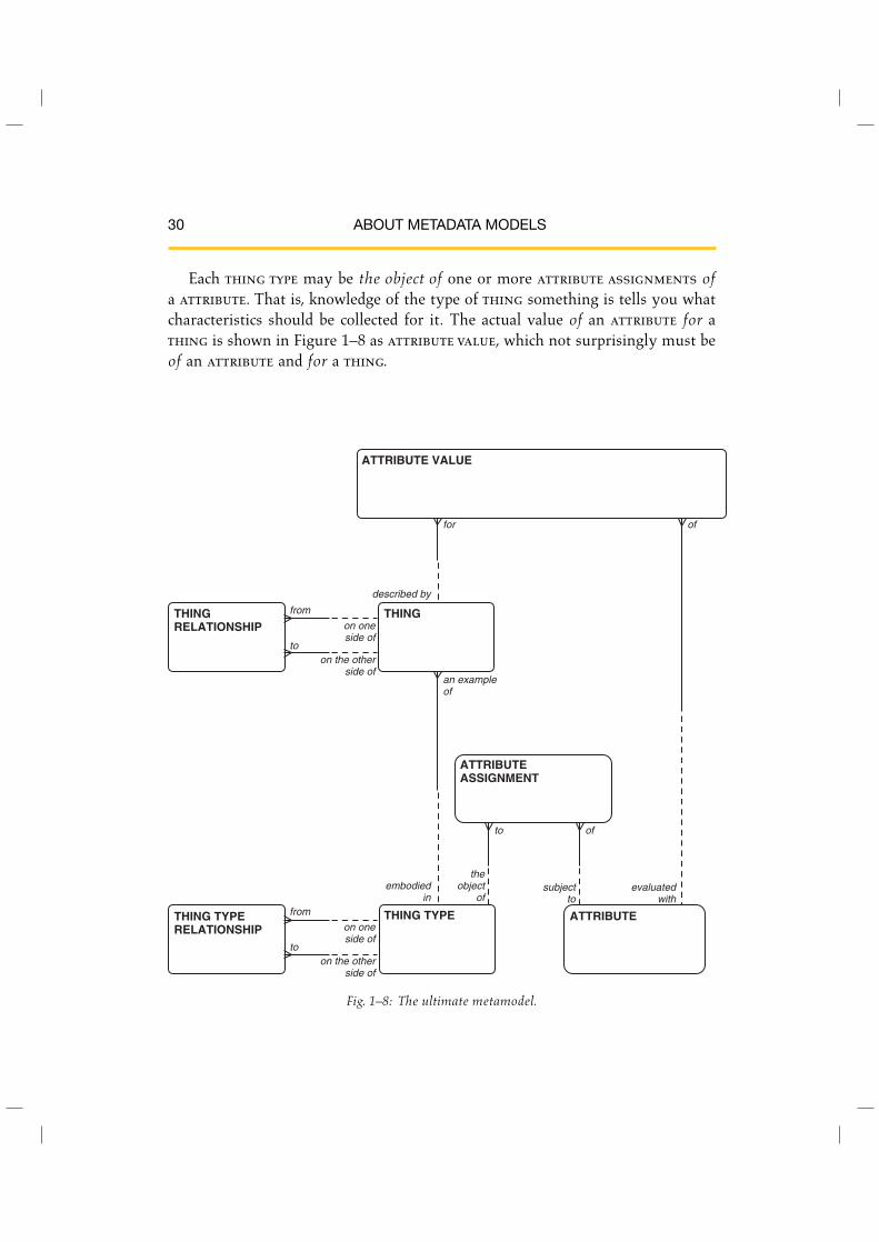
Ultimately, the model of all metadata could be a variation on the one shownin Figure 1–8. Here, all things of interest in the model are represented simply asthing. Each thing must be an example of one and only one thing type, where athing type is the definition of a class of things.
Each thing may be related to another thing, as shown by the relationship thateach thing may be on one side of one or more thing relationships, each of whichis to another thing. Similarly, each thing type may be on one side of one or morething type relationships, each of which is to another thing type.
∗For a more comprehensive comparison of many different notations for doing entity-relationshipmodels, see Appendix B of David C. Hay’s Requirements Analysis: From Business Views toArchitecture [Hay 2003].
30 ABOUT METADATA MODELS
Each thing type may be the object of one or more attribute assignments ofa attribute. That is, knowledge of the type of thing something is tells you whatcharacteristics should be collected for it. The actual value of an attribute for athing is shown in Figure 1–8 as attribute value, which not surprisingly must beof an attribute and for a thing.
ATTRIBUTEASSIGNMENT
THING
ATTRIBUTE VALUE
ATTRIBUTETHING TYPERELATIONSHIP
THING RELATIONSHIP
THING TYPE
from
on oneside of
on the otherside of
to
to of
evaluatedwith
subjectto
from
embodiedin
on one side of
an exampleof
described by
for
on the otherside of
theobject
of
to
of
Fig. 1–8: The ultimate metamodel.

LEVEL OF ABSTRACTION 31
This model can actually describe anything we might want to include in ourrepository. In this case, it could represent entity classes, classes, program units,people, concepts, and the like.
The concrete models we know, then, could each be considered views of this moreabstract model. For example, an entity class could be defined as “a thing that isan example of the thing type ‘entity class’.” Another view could define attribute
as “a thing which is an example of the thing type ‘attribute’.” A thing type rela-
tionship would be defined from thing type “entity class” to thing type “attribute”with the name “described by”. Another thing type relationship would be definedfrom thing type “attribute” to thing type “entity class” with the name “about”.
Actually, the model in Figure 1–8 could made even more abstract by show-ing it as consisting only of thing and thing relationship. After all, theassociation of thing to thing type is itself simply an association between twohigher-level things.
In effect, all entity classes contained in this book are but views of the entityclasses in Figure 1–8.∗ It is perfectly reasonable, then, for a metadata repository tohave a physical structure based on the abstract model of Figure 1–8. This allowsthe tool managing the repository to have the maximum flexibility in addressingfuture requirements. As a description of our metadata business, however, it doesnot tell us very much about what is really going on. When people go to a repositoryfor information, they will want to use a vocabulary considerably richer than this.They will be seeking information about the definition of a business term, when aprogram has been run, or how data are constrained.
It is important, therefore, to present users of the repository with a set of viewsin a vocabulary more appropriate to their needs. For this reason, in this book wemust produce a model that is not quite as abstract as that presented in Figure 1–8.In preparing this book, your author has worked hard to reach the right level ofabstraction. It is for you, the reader, to determine whether he has been successful.
∗But you don’t have to know that in order for them to make sense.