Embed Size (px)
Citation preview
Section 1
Section 2
Section 3
Introduction The company .................................................................................................................................................. 2Quality commitment .................................................................................................................................. 3Quality assurance ......................................................................................................................................... 3Product certification ................................................................................................................................... 3Summary of applicable standards ....................................................................................................... 3Why specify cast iron ................................................................................................................................. 4Why specify Ensign ...................................................................................................................................... 7New Ensign EEZI-FIT ................................................................................................................................... 8Pipes and Fittings – above ground 9Ensign ............................................................................................................................................................... 10Ensign EEZI-FIT ............................................................................................................................................ 29Roof outlets .................................................................................................................................................. 32Pipes and Fittings – below ground 33Floor drains ................................................................................................................................................... 43Couplings – technical 47Coupling specification ............................................................................................................................ 48Electrical continuity ................................................................................................................................. 49Installation high performance ............................................................................................................ 50Jointing method ...........................................................................................................................................51Installation modifications ..................................................................................................................... 52Installation PFJ drain coupling ............................................................................................................ 53EEZI-FIT jointing method ....................................................................................................................... 54Brackets – technical 55Pipe support brackets .............................................................................................................................. 56Support for vertical pipework ............................................................................................................. 56Support for low gradient pipework .................................................................................................. 57Stack support pipe .................................................................................................................................... 58Acoustic brackets ....................................................................................................................................... 59Connections 61Connections to other systems ............................................................................................................ 62Boss pipes compression fit ................................................................................................................... 63Multi-waste manifold connector ...................................................................................................... 64Typical manifold application ............................................................................................................... 64EEZI-FIT manifold application ............................................................................................................. 65EEZI-FIT boss pipe connections ........................................................................................................... 65EEZI-FIT boss branches connections ................................................................................................ 66Typical labour saving devices .............................................................................................................. 67Typical applications – stench trap .................................................................................................... 68Typical applications – long arm branch ......................................................................................... 68Typical applications – movement connector .............................................................................. 69Typical applications – asphalt roof adaptor ................................................................................ 69Roof outlets .................................................................................................................................................. 70Buried Drainage – technical 71Design recommendations ..................................................................................................................... 72Puddle flanges installation details .................................................................................................... 77British Standard fittings ......................................................................................................................... 78Technical Specifications 79Technical specifications ......................................................................................................................... 80Product identification .............................................................................................................................. 81Coating specification ............................................................................................................................... 82Chemical resistance ................................................................................................................................. 84Computer Aided Design (CAD) 85Instructions for use .................................................................................................................................. 86Ensign specifications and clauses ..................................................................................................... 87Ensign EEZI-FIT specification and clauses ..................................................................................... 88
Section 4
Section 5
Section 6
Section 7
Section 8
Contents
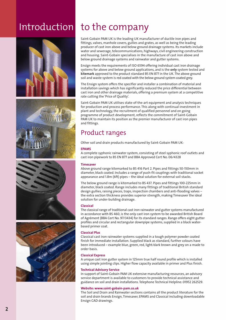
Saint-Gobain PAM UK is the leading UKmanufacturer of ductile iron pipes andfittings, valves,manhole covers, gullies and grates, as well as being the leadingproducer of cast iron above and below ground drainage systems. Its markets includewater and sewerage, telecommunications, highways, civil engineering constructionand housing. Saint-Gobain specialises in the manufacture of cast iron above andbelow ground drainage systems and rainwater and gutter systems.
Ensign meets the requirements of ISO 6594 offering individual cast iron drainagesystems for above and below ground applications, and is the only system tested andkitemark approved to the product standard BS EN 877 in the UK.The above groundsoil and waste system is red coatedwith the belowground system coated grey.
The Ensign system offers the specifier and installer a combination of material andinstallation savings which has significantly reduced the price differential betweencast iron and other drainage materials, offering a premium system at a competitiverate cutting the ‘Price of Quality’.
Saint-Gobain PAM UK utilises state-of-the-art equipment and analysis techniquesfor production and process performance. This along with continual investment inplant and technology, the recruitment of qualified personnel and on goingprogramme of product development, reflects the commitment of Saint-GobainPAM UK to maintain its position as the premier manufacturer of cast iron pipesand fittings.
Product rangesOther soil and drain products manufactured by Saint-Gobain PAM UK:
EPAMSA complete syphonic rainwater system, consisting of steel syphonic roof outlets andcast iron pipework to BS EN 877 and BBA Approved Cert No. 06/4328
TimesaverAbove ground range kitemarked to BS 416 Part 2. Pipes and fittings 50-150mm indiameter, black coated. Includes a range of push-fit couplings with traditional socketappearance and 1.8m (6ft) pipes – the ideal solution for external soil stacks.
The below ground range is kitemarked to BS 437. Pipes and fittings 100-225mm indiameter, black coated. Range includes many fittings of traditional British standarddesign gullies, raising pieces, traps, inspection chambers and anti-flooding valves –the extra section thickness provides superior strength,making Timesaver the idealsolution for under-building drainage.
ClassicalThe classical range of traditional cast iron rainwater and gutter systemsmanufacturedin accordance with BS 460, is the only cast iron system to be awarded British Boardof Agrément (BBA Cert No.97/3434) for its standard ranges. Range offers eight gutterprofiles and circular and rectangular downpipe systems, supplied in a black water-based primer coat.
Classical PlusClassical cast iron rainwater systems supplied in a tough polymer powder coatedfinish for immediate installation. Supplied black as standard, further colours havebeen introduced – example blue, green, red, light/dark brown and grey on a made toorder basis.
Classical ExpressA unique cast iron gutter system in 125mm true half round profile which is installedusing simple jointing clips. Higher flow capacity available in primer and Plus finish.
Technical Advisory ServiceIn support of Saint-Gobain PAMUK extensive manufacturing resources, an advisoryservice department is available to customers to provide technical assistance andguidance on soil and drain installations.Telephone Technical Helpline:01952 262529.
Website:www.saint-gobain-pam.co.ukThe Soil and Drain and Rainwater sections contains all the product literature for thesoil and drain brands Ensign,Timesaver, EPAMS and Classical including downloadableEnsign CAD drawings.
2
Introduction to the company
Environment Standard BS EN ISO 14001:2004Saint-Gobain PAM UKmanufacturing sites including Sinclair, at Telford, havebeen awarded the ‘Manufacturing to Environmental Standards’ accreditationBS EN ISO 14001:2004which was developed to help manufacturers maintain andimprove their management of environmental responsibilities and assist them inensuring compliance with environmental laws and regulations.
Saint-Gobain PAMUK operates Integrated Pollution and Preventative Control (IPPC)regulations and have implemented comprehensive environmental managementsystems throughout the manufacturing sites.
Quality assuranceBS EN ISO 9001:2000 – Registered No: FM12908The Ensign System is manufactured under the BS EN ISO 9001: 2000 QualityAssurance Scheme. Continual checks made throughout the year by the BSIinspectorate, ensure that the set standards are maintained.
Product certificationBS EN 877:1999 Kitemark KM51733Ensign is the only cast iron system to be tested and awarded Kitemark approval tothe product standard in the UK. (See scope below).
Ensign EEZI-FIT has been included in kitemark certificate KM51733 for sanitarygravity applications and 0.5 bar (accidental static water pressure) performance.
BS EN 14366:2004Ensign and EEZI-FIT have been tested to the criteria laid down in BS EN 14366:2004.Laboratory measurement of noise fromwaste water installations at the IBPlaboratory in Stuttgart. A number of test reports are available.
Summary of applicable standardsSTANDARDSEuropean Standard BS EN 877:1999This new Product Standard applies to cast iron pipework elements used for theconstruction, normally as gravity pipe systems, of discharge systems for buildingsand of drains. The range of nominal diameters extends from DN40 to DN600inclusive. This standard specifies the requirements for the materials, dimensionsand tolerances,mechanical properties, appearance and standard coatings for castiron pipes, fittings and accessories. It also indicates performance specifications forall components, including joints. It covers, above ground soil, waste, rainwater andburied systems and performance requirements in these applications.
Product StandardsISO 6594: International standard for socketless drainage systems in cast iron.
BS EN 681/ISO 4633: Specification for elastomeric seals for joints in pipeworkand pipelines.
Codes of Practice StandardsBS EN 12056-2: Code of practice for gravity drainage systems inside buildings– sanitary pipework.
BS EN 12056-3: Code of practice for gravity drainage systems inside buildings– for drainage of roofs.
BS EN 752-1: Code of practice for drain and sewer systems outside buildings.
3
Quality commitment
1 – Fire safety (The Burning Question)The Ensign cast iron drainage system answered the burning question through testscarried out by the MPA North-RhineWestphalia laboratory in Germany. The testswere set up over three floors with the objective to examine the reaction to fire on anumber of materials and to measure their ability to contain the fire within thecompartment, preventing the spread of fire to another floor.
The test results highlighted the limitations of the standard fire collars used on theplastic-based systems tested – in the floor below ALL collars remained inactive.In the case of HDPE, dripping molten droplets passed through the fire collar to thefloor below which generated a further fire outbreak.
In the fire compartment – all plastic type systems tested generated dense,dangerous smoke (the biggest killer in any fire).
Ensign cast iron is non-combustible, does not require any fire protection (approveddocument B), will not propagate fire and will not emit toxic gases like PVC-basedsystems, or sooty smog like HDPE.
2 – Acoustic performance (Hearing is Believing)The Ensign and EEZI-FIT systems have been tested to the new standard BS EN14366:2004 (laboratory measurement of noise fromwaste water installations).
Its surface mass and density results in unquestionable superior performance overUPVC and stainless steel.
Ensign and EEZI-FIT both significantly outperform the latest acoustic-lined plasticsystems and HDPE acoustic systems by up to 10dB(A) for structure-borne noise and4-5dB(A) for airborne-noise. (See page 59).
Therefore, ALL alternative systems to Ensign will require significant levels ofacoustic insulation to match its performance. An allowance of £10 per metre is notuntypical for acoustic pipework insulation,which can develop into a substantial coston multi-storey flats and apartments, a factor often not considered during theselection process in deciding which material best suits the application.
4
1
4
5
6
2
7
8
9
3
Why specify cast iron
3 – No expansion jointsThe co-efficients of linear expansion for cast iron and concrete are almost identical.This makes cast iron a highly suitable material where drainage systems are requiredto pierce concrete floor slabs.
No special jointing to allow for differential expansion is needed. In contrast HDPEand UPVC piping requires an expansion joint every 3metres, as well as expensivethermal limiters.
StrengthCast iron is renowned for its strength and robustness in resisting impact damageand mishandling on site. It is the perfect solution for car parks, shopping centres,schools or generally any exposed areas that are liable to damage.
Less maintenanceThe strength of modern cast iron and improved coatings means that cast irondrainage needs minimal maintenance during the lifetime of the building in normalconditions. This makes cast iron the first choice for concealed, built-in or otherwiseinaccessible systems where access for repair or maintenance would cause a highdegree of inconvenience to the occupants. This benefit of minimal maintenance andlong life service makes cast iron the first choice material for PFI projects.
4 – Resistance to damageThe strength of cast iron means that accessible parts of the drainage system,ie. basement car parks are more resistant to damage than other drainage materials– whether from vandalism or accidental impact.
5 – Ground movementThe demand for building land has resulted in the greater use of made-up landor other locations that may be subject to ground movement. Cast iron belowground offers greater resistance to such movement, and is less likely to fail inunfavourable conditions.
6 – Less embedmentIn areas where ground disturbance or extra loading is likely, other drainagematerials may need additional protection, for example a covering concrete slab or aconcrete surround. Cast iron needs no additional protection in most circumstances,saving time, labour and materials in construction.
7 – Less fixingsBesides the fixings required by fittings,modern cast iron drainage systemsusually need only one load bearing support only every 3metres in vertical stacks –UPVC and HDPE usually requires supporting brackets at every metre, and stainlesssteel every 2metres. (See BS EN 12056-2 Guidelines Table NF.1). Therefore cast ironcan save considerable time, labour and components in construction and steelevery 2metres.
8 – LongevityThere are two elements of an above ground drainage system that should bedesigned and specified to last the lifetime of the building.
1. the internal rainwater pipes2. the soil discharge stacks
Even when a building is modernised every 15 or 20 years, these elements along withthe structure will likely remain. If the toilet or kitchen area is refurbished, thebranch discharge pipes will often be renewed and therefore it may be appropriateto specify other materials for that element.
But if the main stacks are to be specified to last the lifetime of a building, perhaps50-70 years or more, the appropriate material is mechanical jointed cast iron, for it isone of fewmaterials you can reasonably fit and forget, as recognised by specifierson many of the new PFI-type projects.
9 – Resistance to extreme temperaturesFaulty or incorrect bracketing could lead to UPVC and HDPE demonstrating excessivedistortion when subjected to extreme temperatures. Consequently hot environments,or handling hot wastes can cause damage to the UPVC drainage system. Cast iron’slow co-efficient of expansion means it does not have this disadvantage.
5
Why specify cast iron
Sustainable environmentThe environmental concerns of building materials is becoming a major issue for allinvolved in the construction industry. But, those specifying, installing and supplyingcast iron pipes, fittings and accessories, are working with a material that is not onlyrecyclable, but made from almost 100% recycled scrap metals and therefore shouldnot be disposed of in landfill. The extended life span of the system – proven to beover 50 years in many buildings, and extremely longer than other materials –reduces the use of natural resources and protects the environment.
Fit/forget drainageCast iron is often referred to as fit and forget material – impervious to degradationby UV light and most mechanical damage, including aggressive or carelessmaintenance, and with a track record measured in centuries, cast iron is the onlyproven lifetime choice. Prestigious projects worldwide utilise cast iron systems,including multi-storey commercial and residential developments, retail parks,hospitals, schools, car parks and prisons, to name a few.
Risk assessment – damage to buried pipeTo decide which of the threemain types of material for below building use, cast iron,vitrified clay and plastic is appropriate, it is necessary to carry out a risk analysis.
Most engineers would agree that the risk of settlement, sheer pressure and overzealous maintenance methods are potential problems more likely to take a clay orplastic system out of operation than a cast iron one. It can bridge major voidscaused by settlement, resist sheer pressures and successfully take the internalknocks from the rodding.
Hazard Vit clay Plastic Cast iron
Settlement High risk Med risk Low risk
Sheer pressure High risk Low risk Low risk
Rodding damage Med risk High risk Low risk
Courtesy of GTA
The cost of failureIt is accepted that cast iron drainage systems will be least likely to fail in anysituation. In order to establish when the use of cast iron drainage is most appropriatefor any given application, it is best to consider the relative seriousness of theconsequences arising from failure. Here a table has been compiled illustrating howsuch consequences may be compared under a series of different considerations.
Considerations House or Hospital or Retail storesmall commercial commercial/residential
People affected Few Many Many
Potential losses Low High High
Repair type Cut in-situ slab Cut RC slab Cut RC slabor divert pipe
Consequences Disturbance Disturbance DisturbanceNoise Noise NoiseHygiene Hygiene Hygiene
Cost Low High High
Courtesy of GTA
6
Why specify cast iron
Complete pipe systemEnsign fully meets the requirements of Product Standard BS EN 877 providing thecomplete drainage solution to a building needs. Ensign is an above and below grounddrainage system, transporting fluid waste, through the building, out and beyond.Ductile iron couplings with electrical continuityThe Ensign systems are jointed by unique two-piece ductile iron couplings, thatare high performance, quick and easy to install. For above ground applications,the coupling design incorporates iron ‘nibs’which will provide built-in electricalcontinuity. Couplings destined for below ground use do not include this continuityfeature. The coupling naturally meets the requirements of BS EN 877, fully satisfyingthe requirements of IEE Regulations. The couplings incorporate a set screw designutilising hexagonal socket cap screws reducing the threat of wanton dismantling ofcouplings by vandals.Push fit drain couplingsCast iron push-fit joints, that utilise two EPDM rubber gaskets, simplifying installation,providing a flexible alternative to mechanical couplings,when there is opportunityfor fast pipe laying (ie. long straight runs). (See page 53).Ductile iron bracketsIncluded within the range is an all purpose ductile iron bracket, versatile andlightweight, the bracket incorporates an elongated slot at the fixing point allowingadjustment without dismantling the pipe system.Quietest drainage systemEnsign has been tested to the new standard BS EN 14366:2004 (laboratorymeasurement of noise fromwater waste systems) and has achieved exceptionallylow levels recording 11dB(A) at 4 litres/second for structure borne measurement and47dB(A) for airborne measurement,when installed using the ductile iron bracketfitted with the acoustic dampener. Ensign is the quietest cast iron system and as amaterial is quieter than the best plastic system by up to 10dB(A) and up to 20dB(A)quieter than standard HDPE for structure-borne noise. All materials, twin-wall PVC,HDPE, stainless steel require substantial insulation to match the performance ofEnsign. (Full test report available). (See pages 59-60).Easy access for maintenanceThe Ensign system contains an extensive range of access fittings, providing ease ofmaintenance at vital points in the stack to relieve any blockages which may occur.The access door is contoured, specifically designed to unobstruct the flow of wastewithin the pipe system.Economical connections to waste pipesEnsign provides a number of alternative methods to connect to plastic and copperwaste, including ‘compression fit’ boss pipes, that utilise ‘O’ ring rubber compressiongaskets to connect to waste pipes without the need for conventional threadedmale adaptors.Also the popular multi-waste manifold which accommodates up to three wastepipes from various sources such as bath, bidets, and showers to one internal point(see photo to the left). Now available in 100 and 150mm diameters.Superior internal coating for pipesEnsign pipes for above and below ground applications, are now internally lined witha new two-part epoxy (ochre in colour). The new coating has been developed toprovide greater performance against exposure to aggressive substances or hightemperature waste, far exceeding the requirements stipulated in BS EN 877 (seecoating – page 83). The epoxy coated fittingsmatch the performance of the pipes.LightweightThe Ensign system is considerably lighter in weight compared to previous cast ironsystems making it much easier to handle,whilst retaining the inherent strengthqualities of cast iron.The system has been designed to comply with European aboveand below ground applications,which have been well proven over many years.Superior cast iron pipesEnsign pipes are manufactured using the De Lavaud process which undergoes arapid cooling stage followed by a specific dual heat treatment process whichsignificantly improves its mechanical and impact-resistant properties, and makesthe pipes easier to cut.
7
Internal/externalrainwater system
Soil and wastesystem
Suspendeddrainage system
Red coated
Buried drainagesystem
Bridge drainageGrey coated
Why specify Ensign
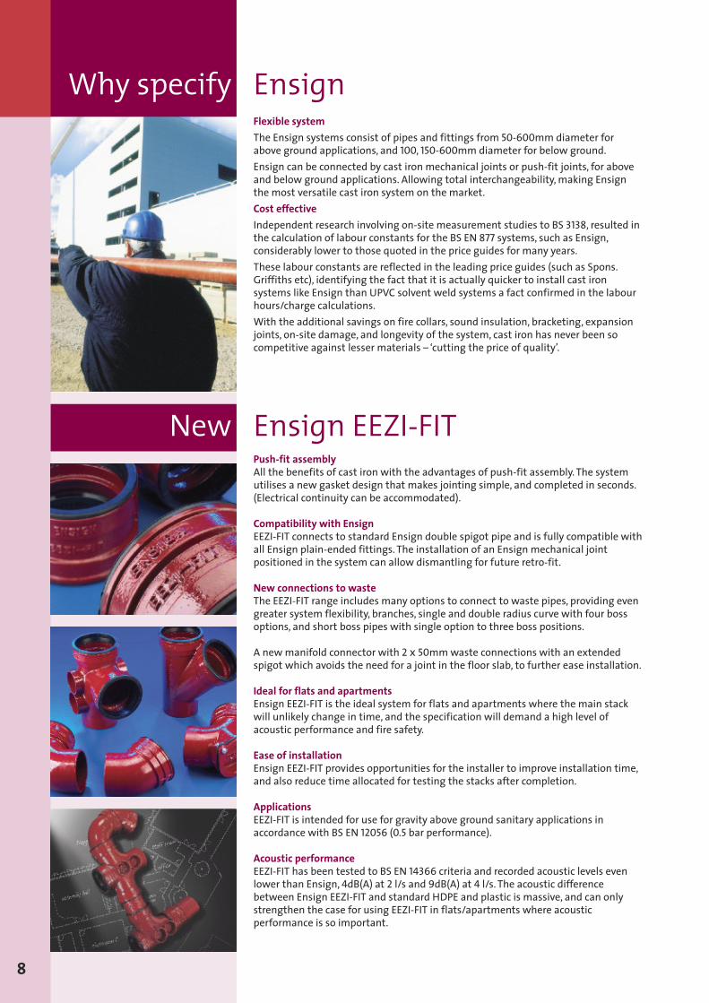
Flexible systemThe Ensign systems consist of pipes and fittings from 50-600mm diameter forabove ground applications, and 100, 150-600mm diameter for below ground.Ensign can be connected by cast iron mechanical joints or push-fit joints, for aboveand below ground applications. Allowing total interchangeability,making Ensignthe most versatile cast iron system on the market.Cost effectiveIndependent research involving on-site measurement studies to BS 3138, resulted inthe calculation of labour constants for the BS EN 877 systems, such as Ensign,considerably lower to those quoted in the price guides for many years.These labour constants are reflected in the leading price guides (such as Spons.Griffiths etc), identifying the fact that it is actually quicker to install cast ironsystems like Ensign than UPVC solvent weld systems a fact confirmed in the labourhours/charge calculations.With the additional savings on fire collars, sound insulation, bracketing, expansionjoints, on-site damage, and longevity of the system, cast iron has never been socompetitive against lesser materials – ‘cutting the price of quality’.
Push-fit assemblyAll the benefits of cast iron with the advantages of push-fit assembly. The systemutilises a new gasket design that makes jointing simple, and completed in seconds.(Electrical continuity can be accommodated).
Compatibility with EnsignEEZI-FIT connects to standard Ensign double spigot pipe and is fully compatible withall Ensign plain-ended fittings. The installation of an Ensign mechanical jointpositioned in the system can allow dismantling for future retro-fit.
New connections to wasteThe EEZI-FIT range includes many options to connect to waste pipes, providing evengreater system flexibility, branches, single and double radius curve with four bossoptions, and short boss pipes with single option to three boss positions.
A newmanifold connector with 2 x 50mmwaste connections with an extendedspigot which avoids the need for a joint in the floor slab, to further ease installation.
Ideal for flats and apartmentsEnsign EEZI-FIT is the ideal system for flats and apartments where the main stackwill unlikely change in time, and the specification will demand a high level ofacoustic performance and fire safety.
Ease of installationEnsign EEZI-FIT provides opportunities for the installer to improve installation time,and also reduce time allocated for testing the stacks after completion.
ApplicationsEEZI-FIT is intended for use for gravity above ground sanitary applications inaccordance with BS EN 12056 (0.5 bar performance).
Acoustic performanceEEZI-FIT has been tested to BS EN 14366 criteria and recorded acoustic levels evenlower than Ensign, 4dB(A) at 2 l/s and 9dB(A) at 4 l/s. The acoustic differencebetween Ensign EEZI-FIT and standard HDPE and plastic is massive, and can onlystrengthen the case for using EEZI-FIT in flats/apartments where acousticperformance is so important.
New Ensign EEZI-FIT
8
Why specify Ensign
Pipes and Fittings– above ground
Sect
ion1
9
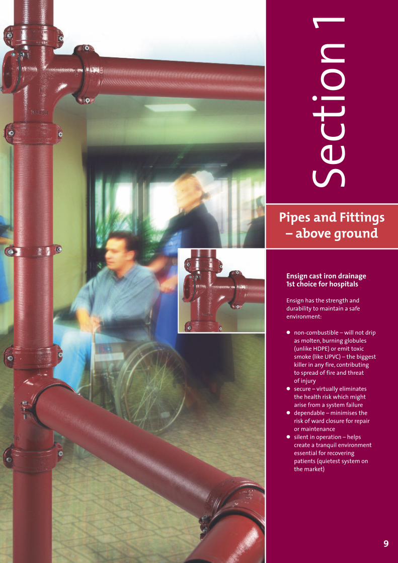
Ensign cast iron drainage1st choice for hospitals
Ensign has the strength anddurability to maintain a safeenvironment:
� non-combustible – will not dripas molten, burning globules(unlike HDPE) or emit toxicsmoke (like UPVC) – the biggestkiller in any fire, contributingto spread of fire and threatof injury
� secure – virtually eliminatesthe health risk which mightarise from a system failure
� dependable – minimises therisk of ward closure for repairor maintenance
� silent in operation – helpscreate a tranquil environmentessential for recoveringpatients (quietest system onthe market)
Pipes double spigot
Couplings
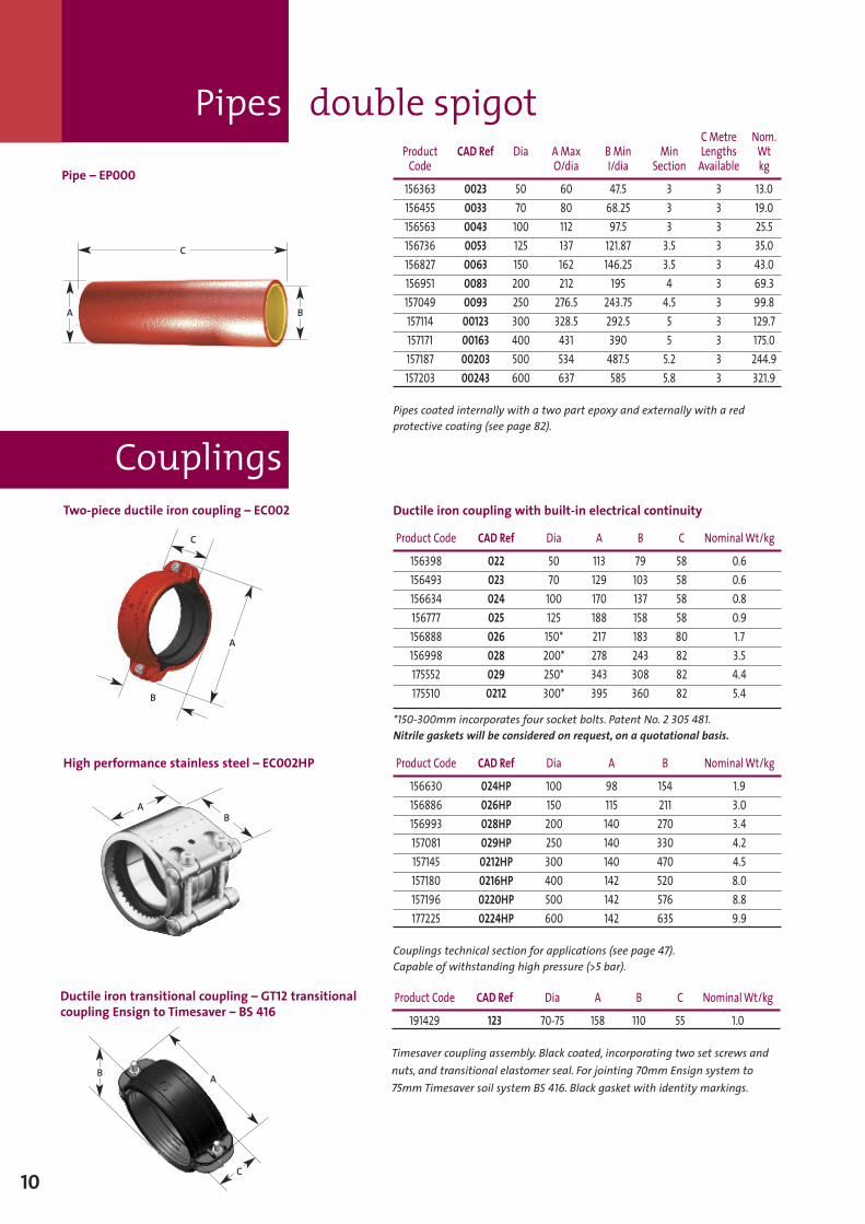
Pipe – EP000
CMetre Nom.Product CAD Ref Dia A Max BMin Min Lengths WtCode O/dia I/dia Section Available kg
156363 0023 50 60 47.5 3 3 13.0156455 0033 70 80 68.25 3 3 19.0156563 0043 100 112 97.5 3 3 25.5156736 0053 125 137 121.87 3.5 3 35.0156827 0063 150 162 146.25 3.5 3 43.0156951 0083 200 212 195 4 3 69.3157049 0093 250 276.5 243.75 4.5 3 99.8157114 00123 300 328.5 292.5 5 3 129.7157171 00163 400 431 390 5 3 175.0157187 00203 500 534 487.5 5.2 3 244.9157203 00243 600 637 585 5.8 3 321.9
Pipes coated internally with a two part epoxy and externally with a redprotective coating (see page 82).
Two-piece ductile iron coupling – EC002
High performance stainless steel – EC002HP
Product Code CAD Ref Dia A B C NominalWt/kg
156398 022 50 113 79 58 0.6156493 023 70 129 103 58 0.6156634 024 100 170 137 58 0.8156777 025 125 188 158 58 0.9156888 026 150* 217 183 80 1.7156998 028 200* 278 243 82 3.5175552 029 250* 343 308 82 4.4175510 0212 300* 395 360 82 5.4
*150-300mm incorporates four socket bolts. Patent No. 2 305 481.Nitrile gaskets will be considered on request, on a quotational basis.
Product Code CAD Ref Dia A B NominalWt/kg
156630 024HP 100 98 154 1.9156886 026HP 150 115 211 3.0156993 028HP 200 140 270 3.4157081 029HP 250 140 330 4.2157145 0212HP 300 140 470 4.5157180 0216HP 400 142 520 8.0157196 0220HP 500 142 576 8.8177225 0224HP 600 142 635 9.9
Couplings technical section for applications (see page 47).Capable of withstanding high pressure (>5 bar).
B
C
A
BA
BA
C
Ductile iron transitional coupling – GT12 transitionalcoupling Ensign to Timesaver – BS 416
Product Code CAD Ref Dia A B C NominalWt/kg
191429 123 70-75 158 110 55 1.0
Timesaver coupling assembly. Black coated, incorporating two set screws andnuts, and transitional elastomer seal. For jointing 70mm Ensign system to75mmTimesaver soil system BS 416. Black gasket with identity markings.
C
B A
Ductile iron coupling with built-in electrical continuity
10
Ensign PFJ
11
Registered Design No. 2 083 167
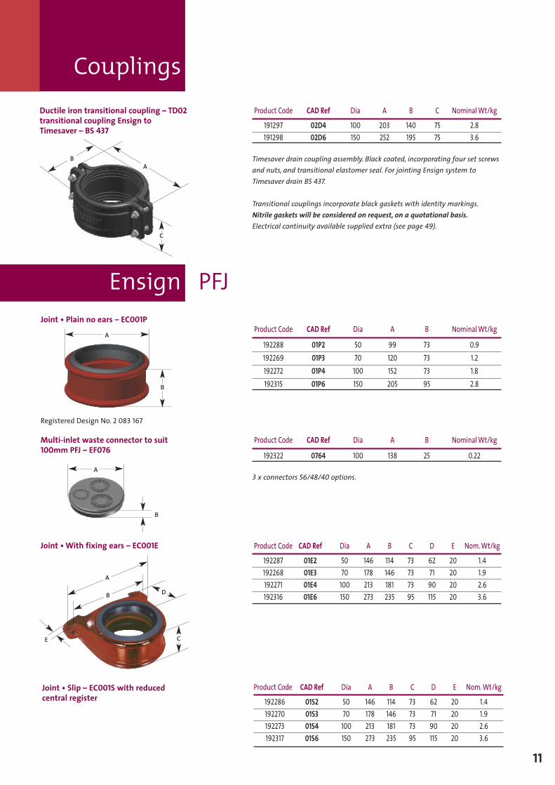
Ductile iron transitional coupling – TD02transitional coupling Ensign toTimesaver – BS 437
Product Code CAD Ref Dia A B C NominalWt/kg
191297 02D4 100 203 140 75 2.8191298 02D6 150 252 195 75 3.6
Timesaver drain coupling assembly. Black coated, incorporating four set screwsand nuts, and transitional elastomer seal. For jointing Ensign system toTimesaver drain BS 437.
Transitional couplings incorporate black gaskets with identity markings.Nitrile gaskets will be considered on request, on a quotational basis.Electrical continuity available supplied extra (see page 49).
Joint • Plain no ears – EC001PProduct Code CAD Ref Dia A B NominalWt/kg
192288 01P2 50 99 73 0.9192269 01P3 70 120 73 1.2192272 01P4 100 152 73 1.8192315 01P6 150 205 95 2.8
A
B
A
C
B
Multi-inlet waste connector to suit100mm PFJ – EF076
Product Code CAD Ref Dia A B NominalWt/kg
192322 0764 100 138 25 0.22
3 x connectors 56/48/40 options.A
B
Couplings
Joint • With fixing ears – EC001E Product Code CAD Ref Dia A B C D E Nom.Wt/kg
192287 01E2 50 146 114 73 62 20 1.4192268 01E3 70 178 146 73 71 20 1.9192271 01E4 100 213 181 73 90 20 2.6192316 01E6 150 273 235 95 115 20 3.6
C
D
E
B
A
Joint • Slip – EC001S with reducedcentral register
Product Code CAD Ref Dia A B C D E Nom.Wt/kg
192286 01S2 50 146 114 73 62 20 1.4192270 01S3 70 178 146 73 71 20 1.9192273 01S4 100 213 181 73 90 20 2.6192317 01S6 150 273 235 95 115 20 3.6
Ensign PFJ
Cast iron wall spacer – EC003 Product Code CAD Ref Dia NominalWt/kg
192296 032 50 0.2192297 033 70 0.2192298 034 100 0.3
To suit eared PFJ EC001E.
Restraining bracket for Ensign PFJ – EF053 Product Code CAD Ref Dia NominalWt/kg
192333 0534 100 0.5
To suit 100mm PFJ Eared EC001E.
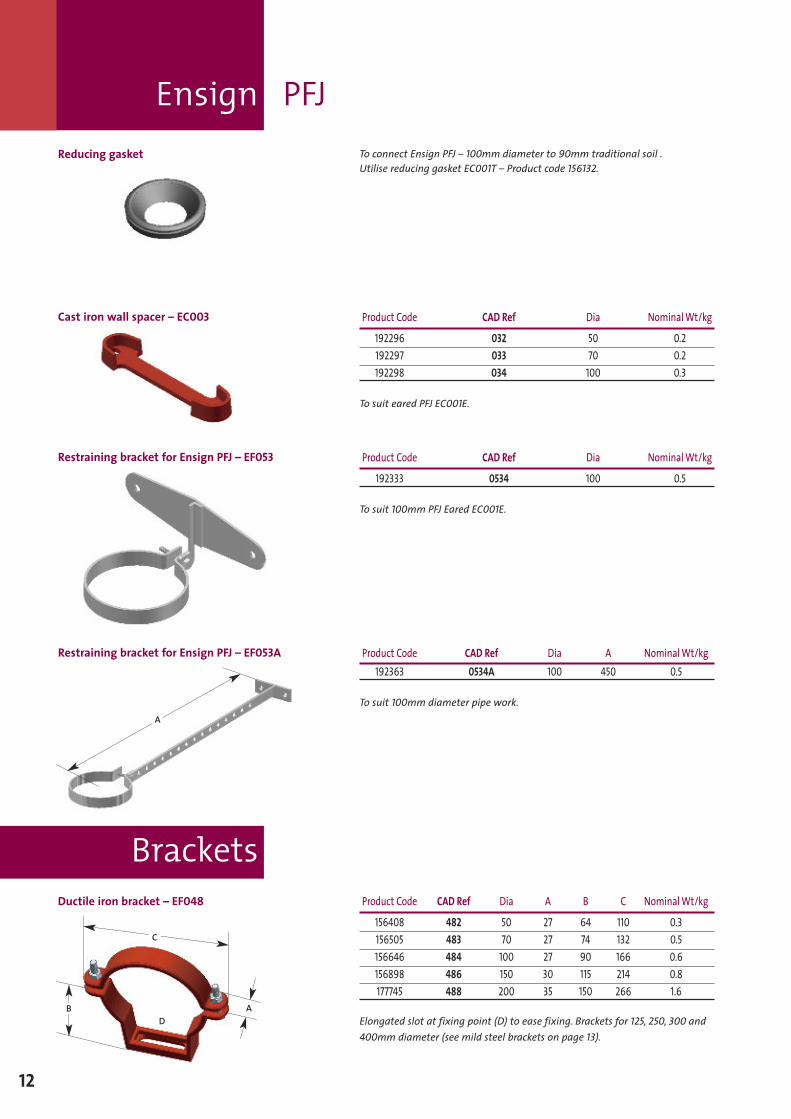
Reducing gasket To connect Ensign PFJ – 100mm diameter to 90mm traditional soil .Utilise reducing gasket EC001T – Product code 156132.
Restraining bracket for Ensign PFJ – EF053A Product Code CAD Ref Dia A NominalWt/kg192363 0534A 100 450 0.5
To suit 100mm diameter pipe work.A
Ductile iron bracket – EF048 Product Code CAD Ref Dia A B C NominalWt/kg
156408 482 50 27 64 110 0.3156505 483 70 27 74 132 0.5156646 484 100 27 90 166 0.6156898 486 150 30 115 214 0.8177745 488 200 35 150 266 1.6
Elongated slot at fixing point (D) to ease fixing. Brackets for 125, 250, 300 and400mm diameter (see mild steel brackets on page 13).
AB
C
D
Brackets
12
Brackets
13
Vertical mild steel bracket – EF048MS Product Code CAD Ref Dia A B C NominalWt/kg
192259 48MS5 125 247 20 M10 0.5
Stand-off mild steel bracket – EF048MS Product Code CAD Ref Dia A B NominalWt/kg
192414 48MS8 200 296 40 1.9192260 48MS10 250 371 40 2.3192261 48MS12 300 420 40 2.6192362 48MS16 400 555 40 3.2
Ductile iron bracket – EF049 Product Code CAD Ref Dia A B C NominalWt/kg
177744 494 100 27 90 166 0.8
Elongated slot at fixing point (D) to ease fixing.
A
C
A
C
B
A
B
B
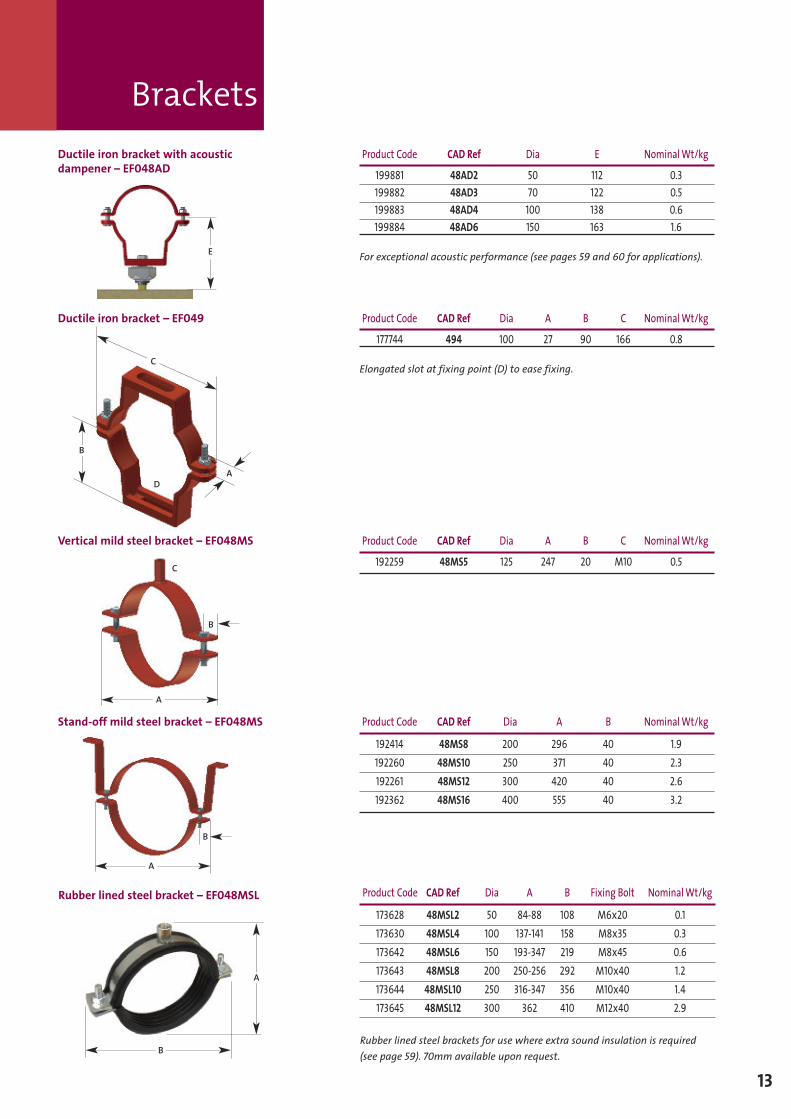
Product Code CAD Ref Dia E NominalWt/kg
199881 48AD2 50 112 0.3199882 48AD3 70 122 0.5199883 48AD4 100 138 0.6199884 48AD6 150 163 1.6
For exceptional acoustic performance (see pages 59 and 60 for applications).
D
Rubber lined steel bracket – EF048MSL Product Code CAD Ref Dia A B Fixing Bolt NominalWt/kg
173628 48MSL2 50 84-88 108 M6x20 0.1173630 48MSL4 100 137-141 158 M8x35 0.3173642 48MSL6 150 193-347 219 M8x45 0.6173643 48MSL8 200 250-256 292 M10x40 1.2173644 48MSL10 250 316-347 356 M10x40 1.4173645 48MSL12 300 362 410 M12x40 2.9
Rubber lined steel brackets for use where extra sound insulation is required(see page 59). 70mm available upon request.
A
E
B
Ductile iron bracket with acousticdampener – EF048AD
Bends short,medium, long radius
14
A
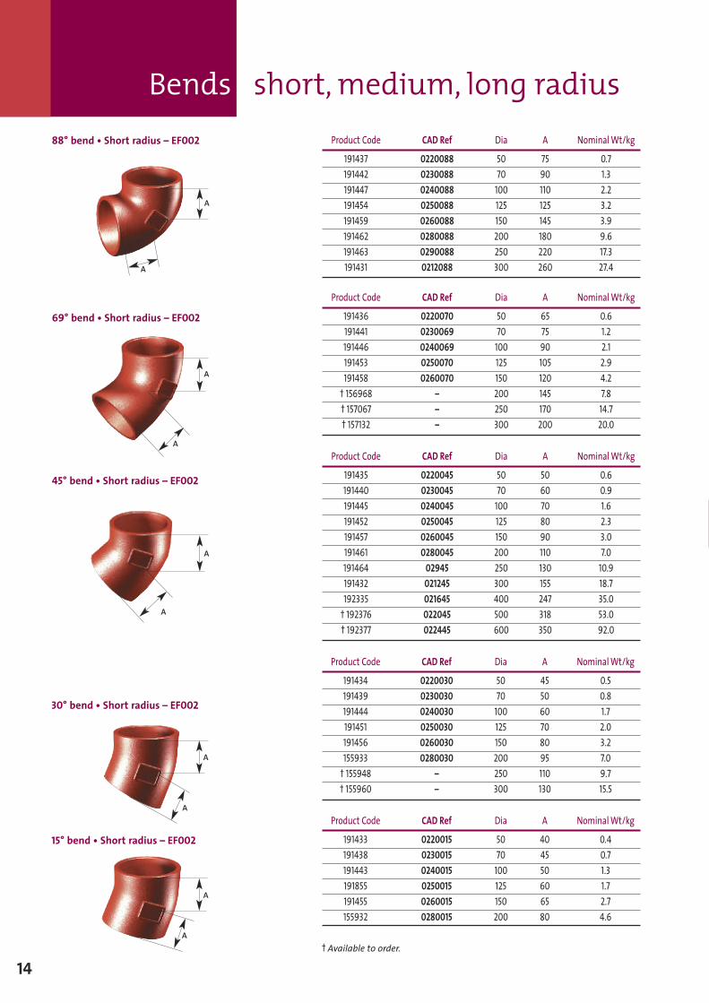
88° bend • Short radius – EF002 Product Code CAD Ref Dia A NominalWt/kg
191437 0220088 50 75 0.7191442 0230088 70 90 1.3191447 0240088 100 110 2.2191454 0250088 125 125 3.2191459 0260088 150 145 3.9191462 0280088 200 180 9.6191463 0290088 250 220 17.3191431 0212088 300 260 27.4
Product Code CAD Ref Dia A NominalWt/kg
191436 0220070 50 65 0.6191441 0230069 70 75 1.2191446 0240069 100 90 2.1191453 0250070 125 105 2.9191458 0260070 150 120 4.2† 156968 – 200 145 7.8† 157067 – 250 170 14.7† 157132 – 300 200 20.0
45° bend • Short radius – EF002
Product Code CAD Ref Dia A NominalWt/kg
191435 0220045 50 50 0.6191440 0230045 70 60 0.9191445 0240045 100 70 1.6191452 0250045 125 80 2.3191457 0260045 150 90 3.0191461 0280045 200 110 7.0191464 02945 250 130 10.9191432 021245 300 155 18.7192335 021645 400 247 35.0† 192376 022045 500 318 53.0† 192377 022445 600 350 92.0
30° bend • Short radius – EF002
Product Code CAD Ref Dia A NominalWt/kg
191434 0220030 50 45 0.5191439 0230030 70 50 0.8191444 0240030 100 60 1.7191451 0250030 125 70 2.0191456 0260030 150 80 3.2155933 0280030 200 95 7.0† 155948 – 250 110 9.7† 155960 – 300 130 15.5
15° bend • Short radius – EF002
Product Code CAD Ref Dia A NominalWt/kg
191433 0220015 50 40 0.4191438 0230015 70 45 0.7191443 0240015 100 50 1.3191855 0250015 125 60 1.7191455 0260015 150 65 2.7155932 0280015 200 80 4.6
† Available to order.
A
A
A
A
A
A
A
A
A
69° bend • Short radius – EF002
Bends medium, long radius
15
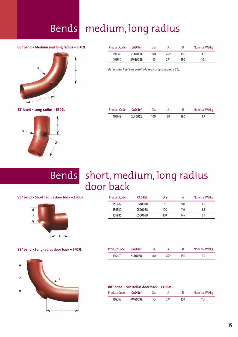
88° bend • Medium and long radius – EF02L Product Code CAD Ref Dia A B NominalWt/kg
191549 2L40088 100 269 180 4.3191550 2M60088 150 274 150 10.1
Bend with heel rest available grey only (see page 36).
88° bend • Short radius door back – EF005 Product Code CAD Ref Dia A NominalWt/kg
156472 0530088 70 90 1.8156589 0540088 100 110 3.3156845 0560088 150 145 6.1
22° bend • Long radius – EF02L Product Code CAD Ref Dia A B NominalWt/kg
191548 2L40022 100 90 180 1.7
A
A
A
A
B
A
A
B
88° bend • Long radius door back – EF05L Product Code CAD Ref Dia A B NominalWt/kg
156607 5L40088 100 269 180 5.5
88° bend • MR radius door back – EF05MProduct Code CAD Ref Dia A B NominalWt/kg
192357 5M60088 150 274 150 11.4
A
A
B
Bends short,medium, long radiusdoor back
Bends long tail
16
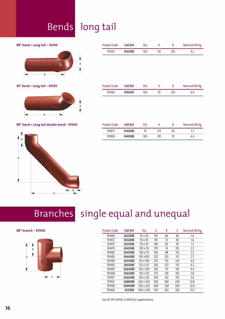
88° bend • Long tail – EF055 Product Code CAD Ref Dia A B NominalWt/kg
191567 5540088 100 110 250 4.2
45° bend • Long tail – EF055 Product Code CAD Ref Dia A B NominalWt/kg
191566 5540045 100 70 250 4.0
B
A
B
A
88° bend • Long tail double bend – EF054 Product Code CAD Ref Dia A B NominalWt/kg
191837 5430088 70 273 60 3.1191838 5440088 100 291 70 4.4
A
88° branch – EF006 Product Code CAD Ref Dia A B C NominalWt/kg191469 0622088 50 x 50 145 66 80 1.0191472 0632088 70 x 50 155 72 90 1.6191475 0633088 70 x 70 180 83 95 1.5191479 0642088 100 x 50 170 76 105 2.3191482 0643088 100 x 70 190 88 110 2.5191485 0644088 100 x100 220 105 115 2.7191490 0654088 125 x 100 235 110 130 4.0191492 0655088 125 x 125 260 123 135 4.2191497 0664088 150 x 100 245 115 145 4.4191499 0665088 150 x 125 275 128 150 5.8191501 0666088 150 x 150 300 142 155 5.8191505 0688088 200 x 200 380 180 200 12.8191508 0699088 250 x 250 468 228 243 22.6191466 6121288 300 x 300 530 265 265 35.5
See BS EN 12056-2:2000 for applications.
A
B
C
B
A
B
Branches single equal and unequal
Branches single equal and unequal
17
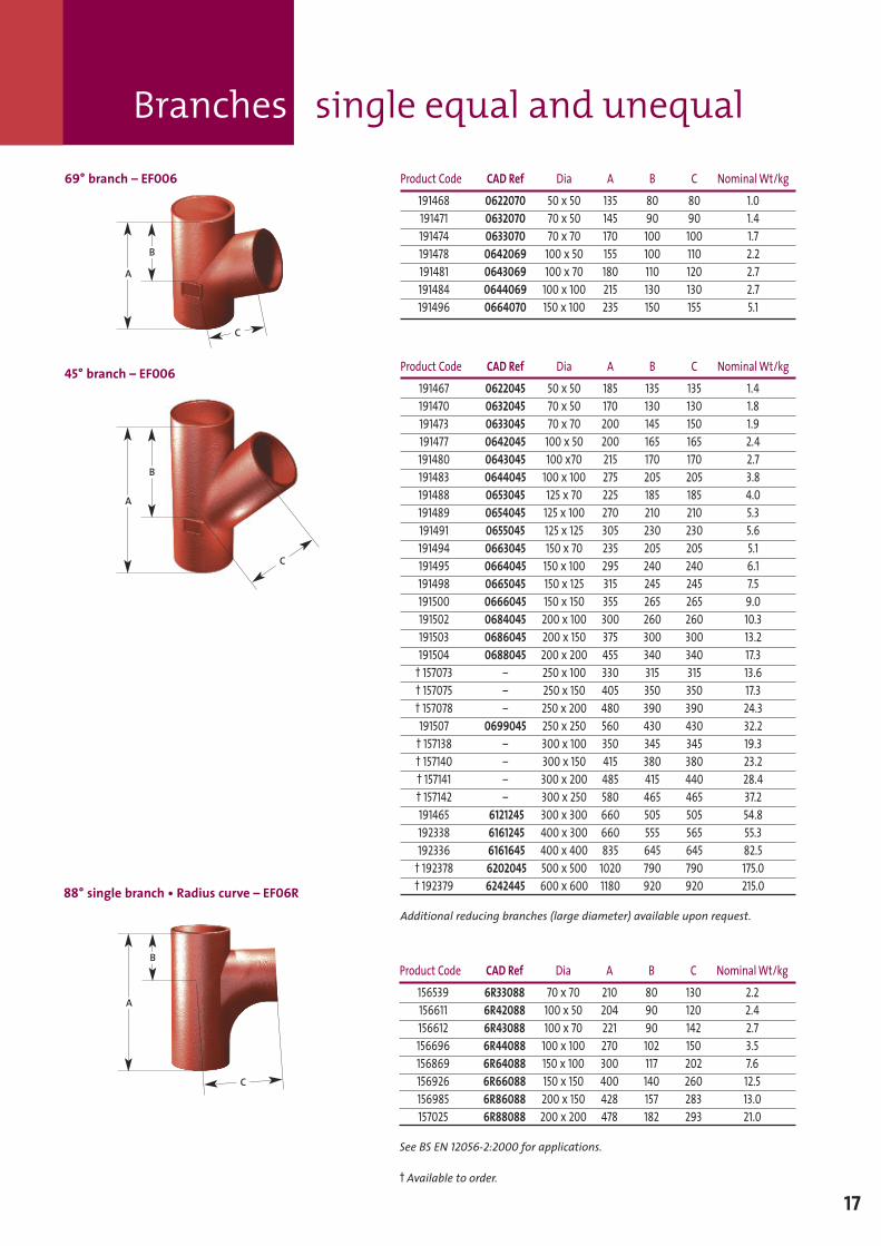
69° branch – EF006 Product Code CAD Ref Dia A B C NominalWt/kg191468 0622070 50 x 50 135 80 80 1.0191471 0632070 70 x 50 145 90 90 1.4191474 0633070 70 x 70 170 100 100 1.7191478 0642069 100 x 50 155 100 110 2.2191481 0643069 100 x 70 180 110 120 2.7191484 0644069 100 x 100 215 130 130 2.7191496 0664070 150 x 100 235 150 155 5.1
A
B
C
45° branch – EF006 Product Code CAD Ref Dia A B C NominalWt/kg191467 0622045 50 x 50 185 135 135 1.4191470 0632045 70 x 50 170 130 130 1.8191473 0633045 70 x 70 200 145 150 1.9191477 0642045 100 x 50 200 165 165 2.4191480 0643045 100 x70 215 170 170 2.7191483 0644045 100 x 100 275 205 205 3.8191488 0653045 125 x 70 225 185 185 4.0191489 0654045 125 x 100 270 210 210 5.3191491 0655045 125 x 125 305 230 230 5.6191494 0663045 150 x 70 235 205 205 5.1191495 0664045 150 x 100 295 240 240 6.1191498 0665045 150 x 125 315 245 245 7.5191500 0666045 150 x 150 355 265 265 9.0191502 0684045 200 x 100 300 260 260 10.3191503 0686045 200 x 150 375 300 300 13.2191504 0688045 200 x 200 455 340 340 17.3† 157073 – 250 x 100 330 315 315 13.6† 157075 – 250 x 150 405 350 350 17.3† 157078 – 250 x 200 480 390 390 24.3191507 0699045 250 x 250 560 430 430 32.2† 157138 – 300 x 100 350 345 345 19.3† 157140 – 300 x 150 415 380 380 23.2† 157141 – 300 x 200 485 415 440 28.4† 157142 – 300 x 250 580 465 465 37.2191465 6121245 300 x 300 660 505 505 54.8192338 6161245 400 x 300 660 555 565 55.3192336 6161645 400 x 400 835 645 645 82.5† 192378 6202045 500 x 500 1020 790 790 175.0† 192379 6242445 600 x 600 1180 920 920 215.0
Additional reducing branches (large diameter) available upon request.
A
B
C
88° single branch • Radius curve – EF06R
Product Code CAD Ref Dia A B C NominalWt/kg156539 6R33088 70 x 70 210 80 130 2.2156611 6R42088 100 x 50 204 90 120 2.4156612 6R43088 100 x 70 221 90 142 2.7156696 6R44088 100 x 100 270 102 150 3.5156869 6R64088 150 x 100 300 117 202 7.6156926 6R66088 150 x 150 400 140 260 12.5156985 6R86088 200 x 150 428 157 283 13.0157025 6R88088 200 x 200 478 182 293 21.0
See BS EN 12056-2:2000 for applications.
† Available to order.
A
B
C
Branches single equal and unequal
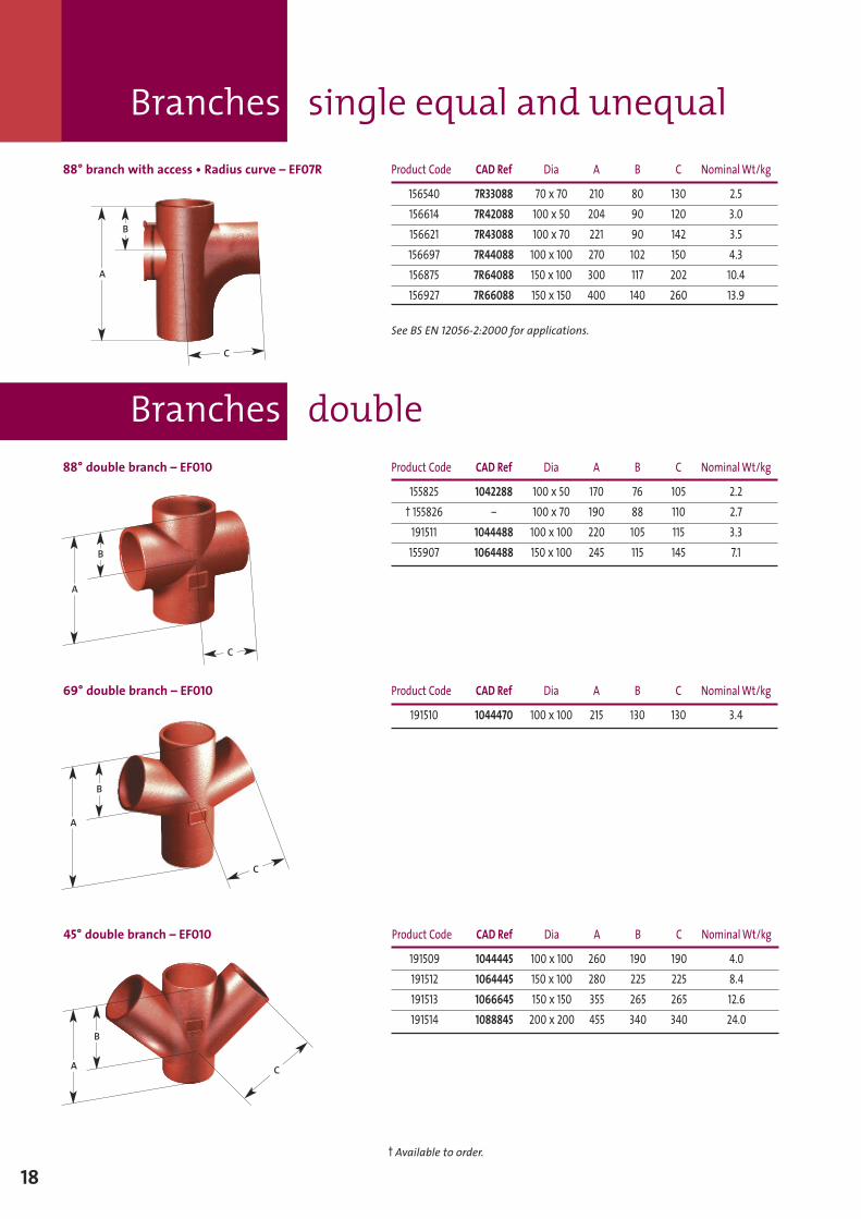
Branches double88° double branch – EF010 Product Code CAD Ref Dia A B C NominalWt/kg
155825 1042288 100 x 50 170 76 105 2.2† 155826 – 100 x 70 190 88 110 2.7191511 1044488 100 x 100 220 105 115 3.3155907 1064488 150 x 100 245 115 145 7.1
A
B
C
69° double branch – EF010 Product Code CAD Ref Dia A B C NominalWt/kg
191510 1044470 100 x 100 215 130 130 3.4
A
B
C
88° branch with access • Radius curve – EF07R Product Code CAD Ref Dia A B C NominalWt/kg
156540 7R33088 70 x 70 210 80 130 2.5156614 7R42088 100 x 50 204 90 120 3.0156621 7R43088 100 x 70 221 90 142 3.5156697 7R44088 100 x 100 270 102 150 4.3156875 7R64088 150 x 100 300 117 202 10.4156927 7R66088 150 x 150 400 140 260 13.9
See BS EN 12056-2:2000 for applications.
A
B
C
45° double branch – EF010 Product Code CAD Ref Dia A B C NominalWt/kg
191509 1044445 100 x 100 260 190 190 4.0191512 1064445 150 x 100 280 225 225 8.4191513 1066645 150 x 150 355 265 265 12.6191514 1088845 200 x 200 455 340 340 24.0
A
B
C
18† Available to order.
Branches double
19
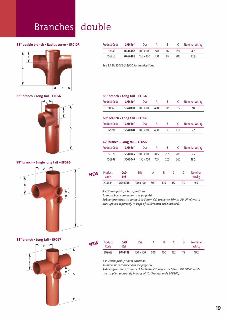
88° branch • Long tail – EF056 88° branch • Long tail – EF056Product Code CAD Ref Dia A B C NominalWt/kg
191568 5644088 100 x 100 430 105 115 7.0
69° branch • Long tail – EF056Product Code CAD Ref Dia A B C NominalWt/kg
156721 5644070 100 x 100 460 130 130 5.2
45° branch • Long tail – EF056Product Code CAD Ref Dia A B C NominalWt/kg
156723 5644045 100 x 100 445 205 205 5.5156938 5666045 150 x 150 705 265 265 18.5
A
B
C
D
B
D
88° double branch • Radius curve – EF010R Product Code CAD Ref Dia A B C NominalWt/kg
157643 0R44488 100 x 100 270 102 150 4.2156862 0R64488 150 x 100 300 115 200 10.9
See BS EN 12056-2:2000 for applications.A
B
C
Product CAD Dia A B C D NominalCode Ref Wt/kg
208644 9644088 100 x 100 500 100 172 75 9.9
4 x 50mm push-fit boss positions.To make boss connections see page 66.Rubber grommets to connect to 54mm OD copper or 56mm OD UPVC wasteare supplied separately in bags of 10. (Product code 208205).
88° branch • Single long tail – EF096
88° branch • Long tail – EF097Product CAD Dia A B C D NominalCode Ref Wt/kg
208653 9744488 100 x 100 500 100 172 75 10.2
4 x 50mm push-fit boss positions.To make boss connections see page 66.Rubber grommets to connect to 54mm OD copper or 56mm OD UPVC wasteare supplied separately in bags of 10. (Product code 208205).
NEW
NEW
A
B
A
C
C
Branches corner
20
C
A
B
C
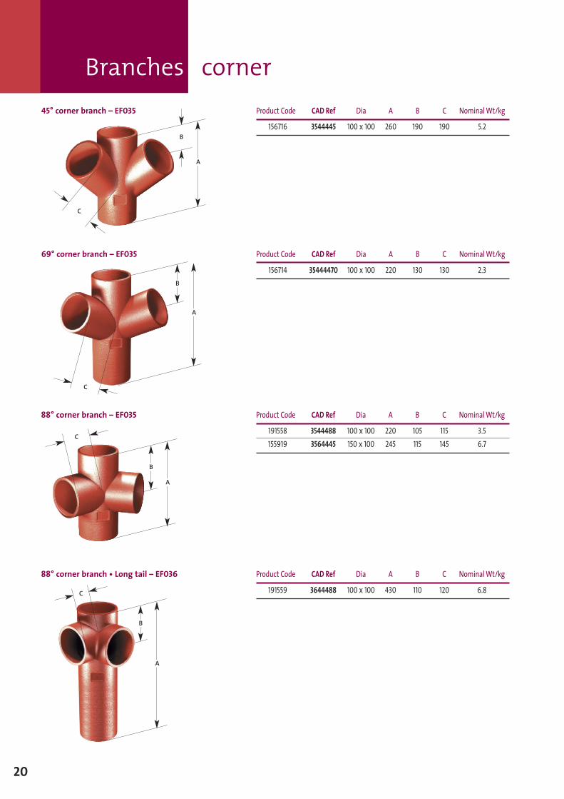
45° corner branch – EF035 Product Code CAD Ref Dia A B C NominalWt/kg
156716 3544445 100 x 100 260 190 190 5.2
69° corner branch – EF035 Product Code CAD Ref Dia A B C NominalWt/kg
156714 35444470 100 x 100 220 130 130 2.3
A
B
88° corner branch • Long tail – EF036 Product Code CAD Ref Dia A B C NominalWt/kg
191559 3644488 100 x 100 430 110 120 6.8
A
B
C
88° corner branch – EF035 Product Code CAD Ref Dia A B C NominalWt/kg
191558 3544488 100 x 100 220 105 115 3.5155919 3564445 150 x 100 245 115 145 6.7
A
B
C
Round door – EF014
A
C
B
A
B
Branches single long arm
21
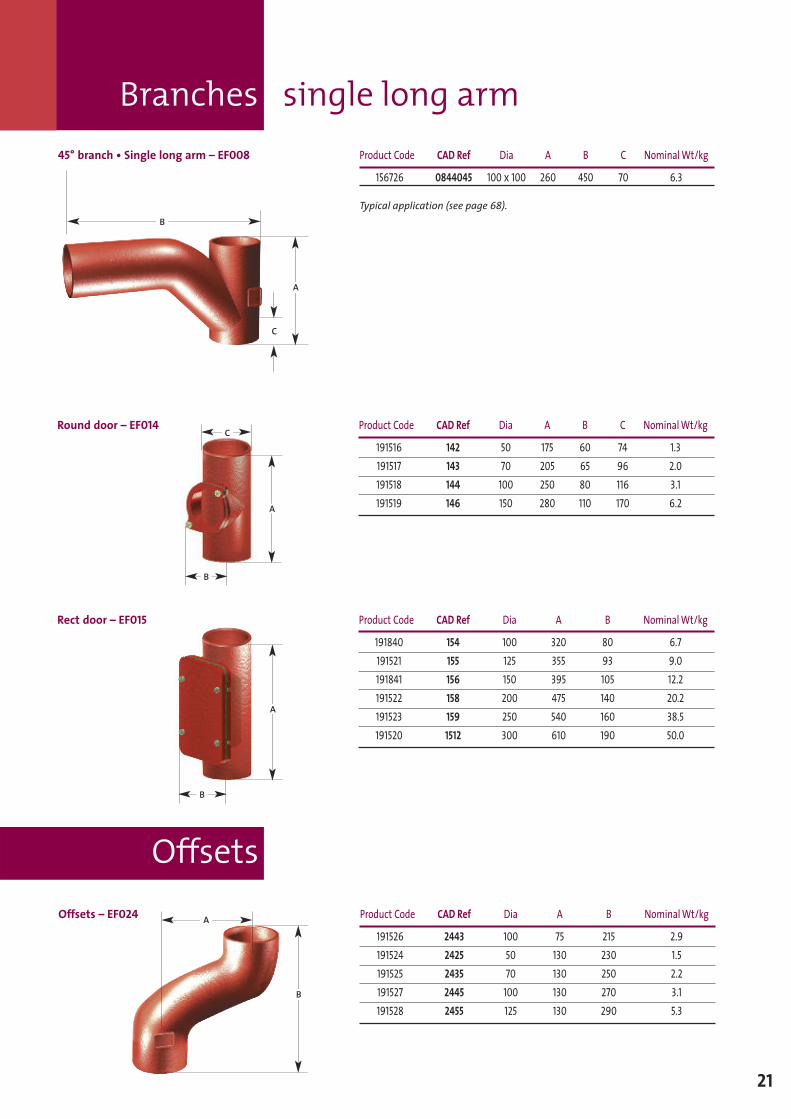
45° branch • Single long arm – EF008 Product Code CAD Ref Dia A B C NominalWt/kg
156726 0844045 100 x 100 260 450 70 6.3
Typical application (see page 68).
A
C
B
Product Code CAD Ref Dia A B C NominalWt/kg
191516 142 50 175 60 74 1.3191517 143 70 205 65 96 2.0191518 144 100 250 80 116 3.1191519 146 150 280 110 170 6.2
Rect door – EF015 Product Code CAD Ref Dia A B NominalWt/kg
191840 154 100 320 80 6.7191521 155 125 355 93 9.0191841 156 150 395 105 12.2191522 158 200 475 140 20.2191523 159 250 540 160 38.5191520 1512 300 610 190 50.0
OffsetsOffsets – EF024 Product Code CAD Ref Dia A B NominalWt/kg
191526 2443 100 75 215 2.9191524 2425 50 130 230 1.5191525 2435 70 130 250 2.2191527 2445 100 130 270 3.1191528 2455 125 130 290 5.3
B
A
Traps
Pipes tapered
22
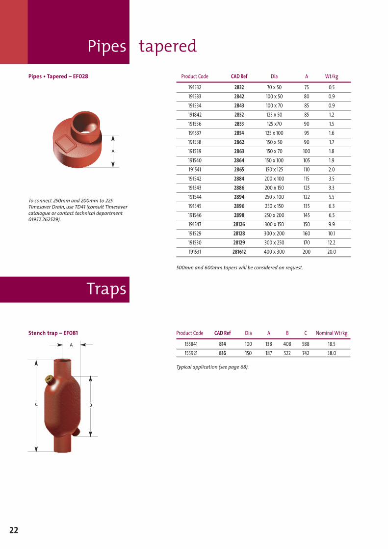
Pipes • Tapered – EF028 Product Code CAD Ref Dia A Wt/kg
191532 2832 70 x 50 75 0.5191533 2842 100 x 50 80 0.9191534 2843 100 x 70 85 0.9191842 2852 125 x 50 85 1.2191536 2853 125 x70 90 1.5191537 2854 125 x 100 95 1.6191538 2862 150 x 50 90 1.7191539 2863 150 x 70 100 1.8191540 2864 150 x 100 105 1.9191541 2865 150 x 125 110 2.0191542 2884 200 x 100 115 3.5191543 2886 200 x 150 125 3.3191544 2894 250 x 100 122 5.5191545 2896 250 x 150 135 6.3191546 2898 250 x 200 145 6.5191547 28126 300 x 150 150 9.9191529 28128 300 x 200 160 10.1191530 28129 300 x 250 170 12.2191531 281612 400 x 300 200 20.0
500mm and 600mm tapers will be considered on request.
A
To connect 250mm and 200mm to 225Timesaver Drain, use TD41 (consult Timesavercatalogue or contact technical department01952 262529).
Stench trap – EF081 Product Code CAD Ref Dia A B C NominalWt/kg
155841 814 100 138 408 588 18.5155921 816 150 187 522 742 38.0
Typical application (see page 68).
C
A
B
Traps
23
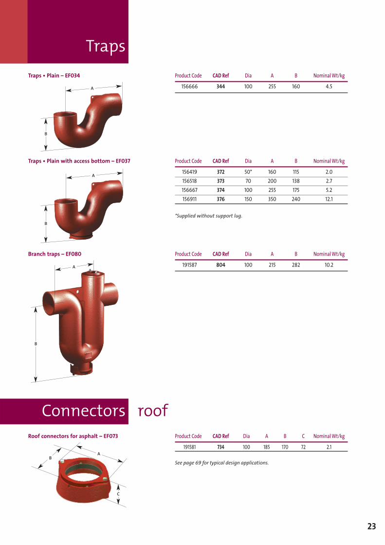
Connectors roofRoof connectors for asphalt – EF073 Product Code CAD Ref Dia A B C NominalWt/kg
191581 734 100 185 170 72 2.1
See page 69 for typical design applications.
AB
C
Traps • Plain – EF034 Product Code CAD Ref Dia A B NominalWt/kg
156666 344 100 255 160 4.5
Branch traps – EF080 Product Code CAD Ref Dia A B NominalWt/kg
191587 804 100 215 282 10.2
Traps • Plain with access bottom – EF037 Product Code CAD Ref Dia A B NominalWt/kg
156419 372 50* 160 115 2.0156518 373 70 200 138 2.7156667 374 100 255 175 5.2156911 376 150 350 240 12.1
*Supplied without support lug.B
A
B
A
B
A
Connectors and pipes – transitional
Connectors universal
Blank ends
Connectors movement
24
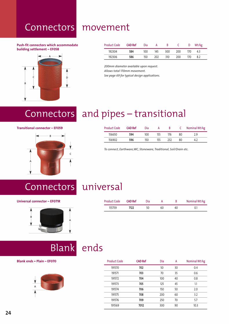
Blank ends • Plain – EF070 Product Code CAD Ref Dia A NominalWt/kg
191570 702 50 30 0.4191571 703 70 35 0.6191572 704 100 40 0.8191573 705 125 45 1.1191574 706 150 50 2.0191575 708 200 60 3.2191576 709 250 70 5.7191569 7012 300 90 10.3
A
Push-fit connectors which accommodatebuilding settlement – EF058
Product Code CAD Ref Dia A B C D Wt/kg
192304 584 100 145 300 200 170 4.3192306 586 150 202 310 200 170 8.2
200mm diameter available upon request.Allows total 170mmmovement.See page 69 for typical design applications.
Transitional connector – EF059 Product Code CAD Ref Dia A B C NominalWt/kg
156650 594 100 155 176 80 2.9156902 596 150 155 232 80 4.2
To connect, Earthware,WC, Stoneware, Traditional, Soil/Drain etc.
Universal connector – EF071R Product Code CAD Ref Dia A B NominalWt/kg
155759 7122 50 60 40 0.1
B
A
C
A
B
C D
AB
Blank ends
25
Expansion plugs
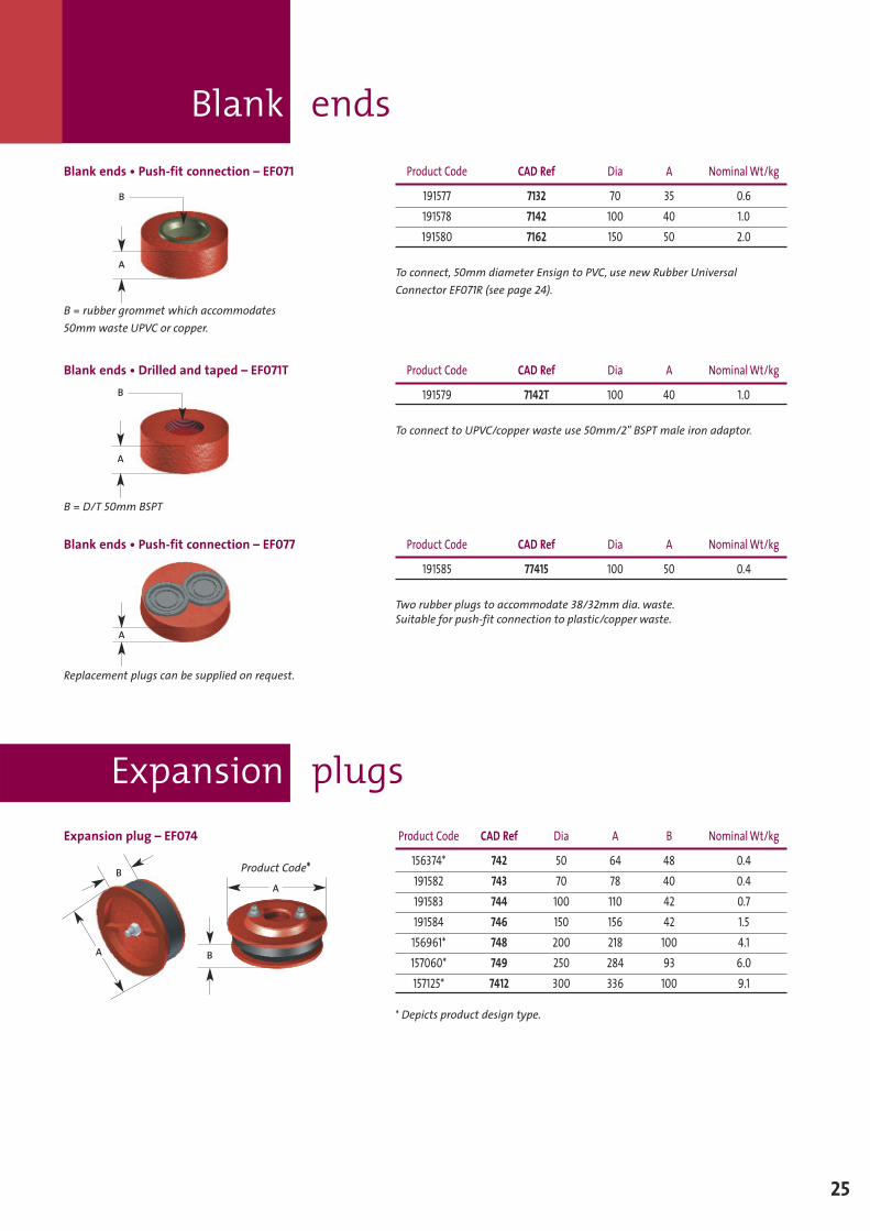
Blank ends • Push-fit connection – EF071 Product Code CAD Ref Dia A NominalWt/kg
191577 7132 70 35 0.6191578 7142 100 40 1.0191580 7162 150 50 2.0
To connect, 50mm diameter Ensign to PVC, use new Rubber UniversalConnector EF071R (see page 24).
Blank ends • Push-fit connection – EF077 Product Code CAD Ref Dia A NominalWt/kg
191585 77415 100 50 0.4
Two rubber plugs to accommodate 38/32mm dia. waste.Suitable for push-fit connection to plastic/copper waste.
Blank ends • Drilled and taped – EF071T Product Code CAD Ref Dia A NominalWt/kg
191579 7142T 100 40 1.0
To connect to UPVC/copper waste use 50mm/2" BSPT male iron adaptor.
Expansion plug – EF074 Product Code CAD Ref Dia A B NominalWt/kg
156374* 742 50 64 48 0.4191582 743 70 78 40 0.4191583 744 100 110 42 0.7191584 746 150 156 42 1.5156961* 748 200 218 100 4.1157060* 749 250 284 93 6.0157125* 7412 300 336 100 9.1
* Depicts product design type.
A
B
B = rubber grommet which accommodates50mmwaste UPVC or copper.
B = D/T 50mm BSPT
Replacement plugs can be supplied on request.
Product Code*
A
A
B
A
B
A
B
support bracketStack support bracket
Stack support pipe
26
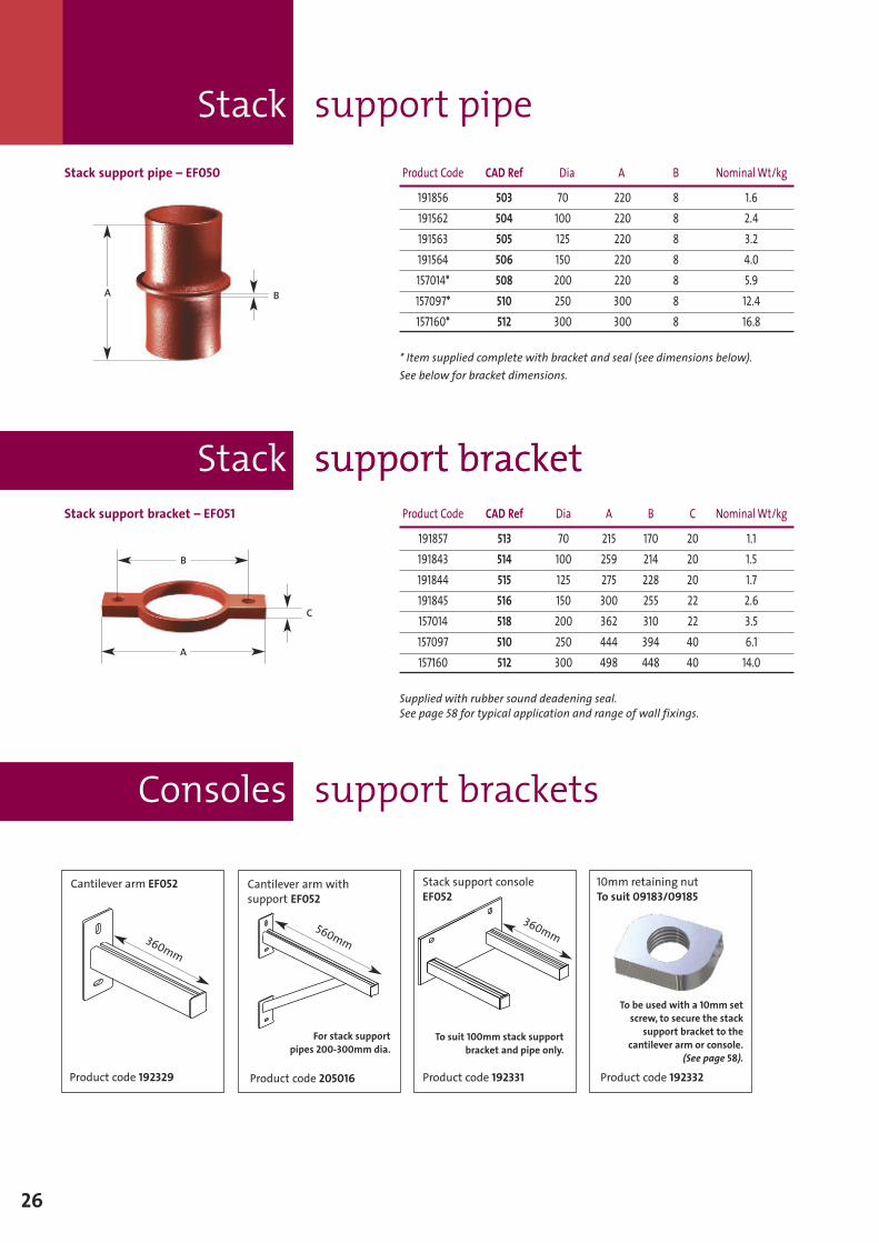
Stack support pipe – EF050 Product Code CAD Ref Dia A B NominalWt/kg
191856 503 70 220 8 1.6191562 504 100 220 8 2.4191563 505 125 220 8 3.2191564 506 150 220 8 4.0157014* 508 200 220 8 5.9157097* 510 250 300 8 12.4157160* 512 300 300 8 16.8
* Item supplied complete with bracket and seal (see dimensions below).See below for bracket dimensions.
BA
Stack support bracket – EF051 Product Code CAD Ref Dia A B C NominalWt/kg
191857 513 70 215 170 20 1.1191843 514 100 259 214 20 1.5191844 515 125 275 228 20 1.7191845 516 150 300 255 22 2.6157014 518 200 362 310 22 3.5157097 510 250 444 394 40 6.1157160 512 300 498 448 40 14.0
Supplied with rubber sound deadening seal.See page 58 for typical application and range of wall fixings.
C
A
B
Consoles support brackets
Cantilever arm withsupport EF052
Cantilever arm EF052
360mm
Stack support consoleEF052
10mm retaining nutTo suit 09183/09185
Product code 205016Product code 192329 Product code 192331 Product code 192332
360mm560mm
For stack supportpipes 200-300mm dia.
To suit 100mm stack supportbracket and pipe only.
To be used with a 10mm setscrew, to secure the stack
support bracket to thecantilever arm or console.
(See page 58).
Boss pipes
27
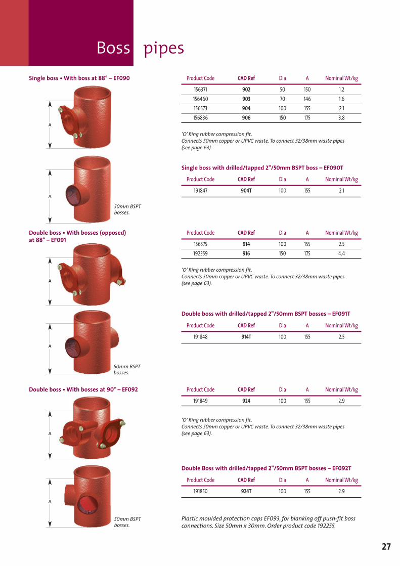
Double boss •With bosses at 90° – EF092 Product Code CAD Ref Dia A NominalWt/kg
191849 924 100 155 2.9
‘O’ Ring rubber compression fit.Connects 50mm copper or UPVC waste. To connect 32/38mmwaste pipes(see page 63).
A
A
A
A
Double boss •With bosses (opposed)at 88° – EF091
Product Code CAD Ref Dia A NominalWt/kg
156575 914 100 155 2.5192359 916 150 175 4.4
‘O’ Ring rubber compression fit.Connects 50mm copper or UPVC waste. To connect 32/38mmwaste pipes(see page 63).
50mm BSPTbosses.
50mm BSPTbosses.
Product Code CAD Ref Dia A NominalWt/kg
191848 914T 100 155 2.5
Double boss with drilled/tapped 2"/50mm BSPT bosses – EF091T
Double Boss with drilled/tapped 2"/50mm BSPT bosses – EF092T
Plastic moulded protection caps EF093, for blanking off push-fit bossconnections. Size 50mm x 30mm.Order product code 192255.
Product Code CAD Ref Dia A NominalWt/kg
191850 924T 100 155 2.9
Single boss •With boss at 88° – EF090 Product Code CAD Ref Dia A NominalWt/kg
156371 902 50 150 1.2156460 903 70 146 1.6156573 904 100 155 2.1156836 906 150 175 3.8
‘O’ Ring rubber compression fit.Connects 50mm copper or UPVC waste. To connect 32/38mmwaste pipes(see page 63).
A
A
50mm BSPTbosses.
Product Code CAD Ref Dia A NominalWt/kg
191847 904T 100 155 2.1
Single boss with drilled/tapped 2"/50mm BSPT boss – EF090T
Strap-on boss fitting
Multi manifold
28
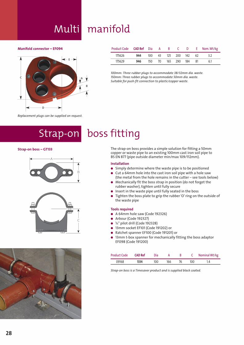
Manifold connector – EF094 Product Code CAD Ref Dia A B C D E Nom.Wt/kg
175626 944 100 43 125 200 142 62 3.2175629 946 150 70 165 290 184 81 6.1
100mm: Three rubber plugs to accommodate 38/32mm dia. waste.150mm: Three rubber plugs to accommodate 50mm dia. waste.Suitable for push-fit connection to plastic/copper waste.
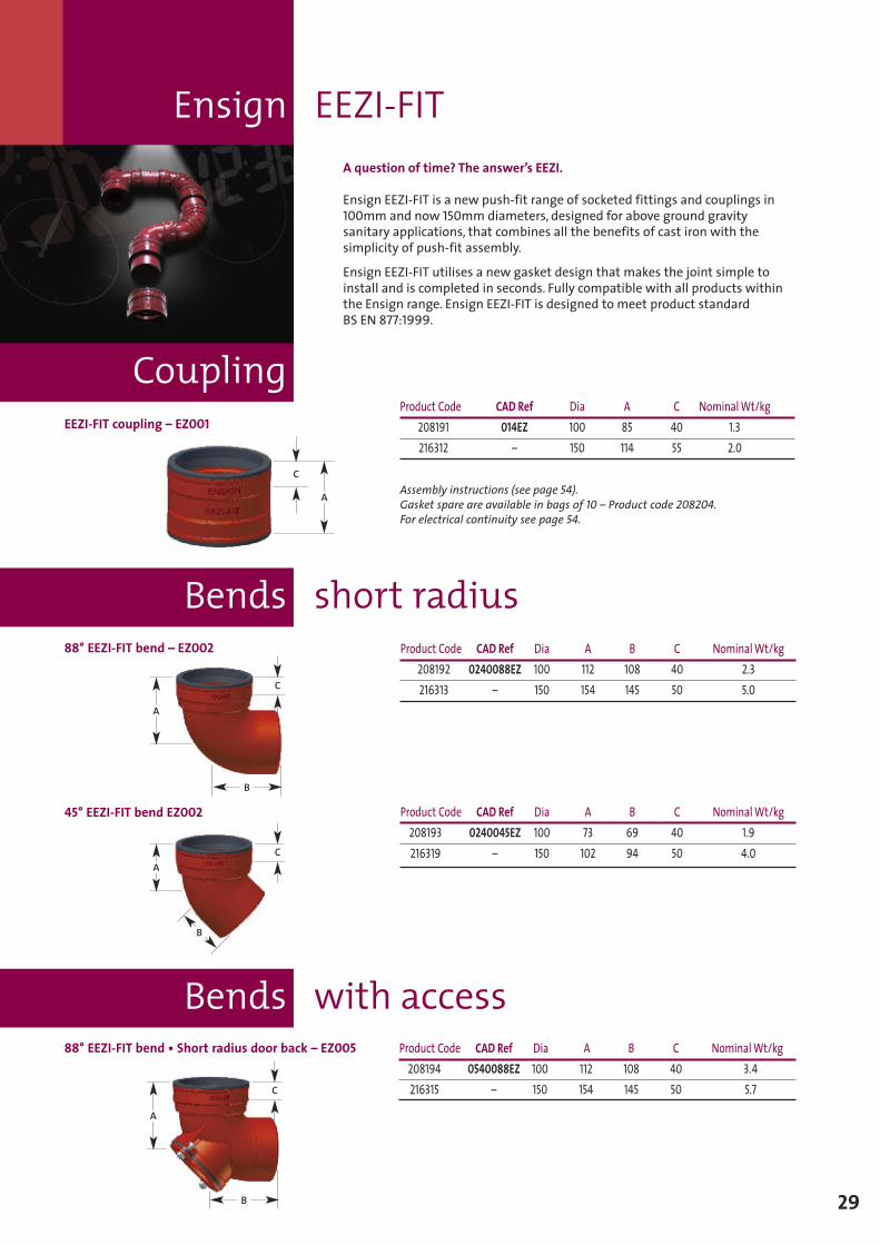
The strap-on boss provides a simple solution for fitting a 50mmcopper or waste pipe to an existing 100mm cast iron soil pipe toBS EN 877 (pipe outside diameter min/max 109/112mm).
Installation� Simply determine where the waste pipe is to be positioned� Cut a 64mmhole into the cast iron soil pipe with a hole saw
(the metal from the hole remains in the cutter – see tools below)� Mechanically fit the boss strap in position (do not forget the
rubber washer), tighten until fully secure� Insert in the waste pipe until fully seated in the boss� Tighten the boss plate to grip the rubber ‘O’ ring on the outside of
the waste pipe
Tools required� A 64mmhole saw (Code 192326)� Arbour (Code 192327)� 1/4" pilot drill (Code 192328)� 13mm socket EF101 (Code 191202) or� Ratchet spanner EF100 (Code 191201) or� 13mm t-box spanner for mechanically fitting the boss adaptor
EF098 (Code 191200)
Product Code CAD Ref Dia A B C NominalWt/kg
09168 1334 100 166 76 100 1.4
Strap-on boss is a Timesaver product and is supplied black coated.
Replacement plugs can be supplied on request.
C
D
A
B
E
Strap-on boss – GT133
Coupling
Bends short radius
Bends with access
Ensign EEZI-FIT
29
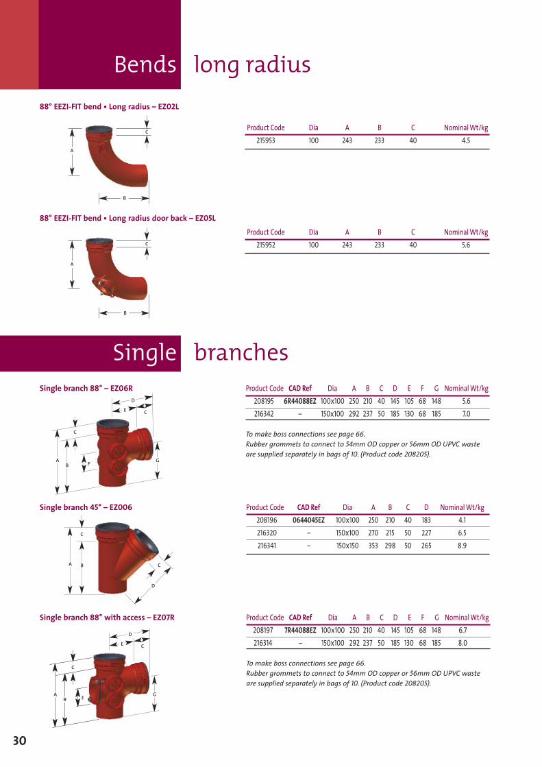
A question of time? The answer’s EEZI.
Ensign EEZI-FIT is a new push-fit range of socketed fittings and couplings in100mm and now 150mm diameters, designed for above ground gravitysanitary applications, that combines all the benefits of cast iron with thesimplicity of push-fit assembly.
Ensign EEZI-FIT utilises a new gasket design that makes the joint simple toinstall and is completed in seconds. Fully compatible with all products withinthe Ensign range. Ensign EEZI-FIT is designed to meet product standardBS EN 877:1999.
Product Code CAD Ref Dia A C NominalWt/kg208191 014EZ 100 85 40 1.3216312 – 150 114 55 2.0
Assembly instructions (see page 54).Gasket spare are available in bags of 10 – Product code 208204.For electrical continuity see page 54.
C
A
Product Code CAD Ref Dia A B C NominalWt/kg208192 0240088EZ 100 112 108 40 2.3216313 – 150 154 145 50 5.0
Product Code CAD Ref Dia A B C NominalWt/kg208193 0240045EZ 100 73 69 40 1.9216319 – 150 102 94 50 4.0
A
B
C
A
B
C
Product Code CAD Ref Dia A B C NominalWt/kg208194 0540088EZ 100 112 108 40 3.4216315 – 150 154 145 50 5.7
A
B
C
88° EEZI-FIT bend – EZ002
88° EEZI-FIT bend • Short radius door back – EZ005
45° EEZI-FIT bend EZ002
EEZI-FIT coupling – EZ001
Bends long radius
30
Single branch 88° – EZ06R
Single branches
Single branch 45° – EZ006
Single branch 88° with access – EZ07R
Product Code CAD Ref Dia A B C D NominalWt/kg208196 0644045EZ 100x100 250 210 40 183 4.1216320 – 150x100 270 215 50 227 6.5216341 – 150x150 353 298 50 265 8.9
A
C
D
C
Product Code CAD Ref Dia A B C D E F G NominalWt/kg208195 6R44088EZ 100x100 250 210 40 145 105 68 148 5.6216342 – 150x100 292 237 50 185 130 68 185 7.0
To make boss connections see page 66.Rubber grommets to connect to 54mm OD copper or 56mm OD UPVC wasteare supplied separately in bags of 10. (Product code 208205).
G
C
D
E
A
C
B F
Product Code CAD Ref Dia A B C D E F G NominalWt/kg208197 7R44088EZ 100x100 250 210 40 145 105 68 148 6.7216314 – 150x100 292 237 50 185 130 68 185 8.0
To make boss connections see page 66.Rubber grommets to connect to 54mm OD copper or 56mm OD UPVC wasteare supplied separately in bags of 10. (Product code 208205).
A G
C
C
B FA
C
B F
D
E
Product Code Dia A B C NominalWt/kg215953 100 243 233 40 4.5
Product Code Dia A B C NominalWt/kg215952 100 243 233 40 5.6
A
B
C
C
A
B
B
88° EEZI-FIT bend • Long radius door back – EZ05L
88° EEZI-FIT bend • Long radius – EZ02L
B
A
B
A
AB
Double branch
31
Double bosspipe 2 x 50mm– EZ091
Double boss pipe2 x 50mmat 90° – EZ092
Triple boss pipe3 x 50mm – EZ093
A
Product Code CAD Ref Dia A B NominalWt/kg208199 904EZ 100 158 82 2.1
Supplied with rubber grommets to connect to 54mm OD copper or 56mm ODUPVC waste. For connections to 38/32 waste – see page 65.
Product Code CAD Ref Dia A B NominalWt/kg208200 914EZ 100 158 82 2.3
Supplied with rubber grommets to connect to 54mm OD copper or 56mm ODUPVC waste. For connections to 38/32 waste – see page 65.
Product Code CAD Ref Dia A B NominalWt/kg208201 924EZ 100 158 82 2.3
Supplied with rubber grommets to connect to 54mm OD copper or 56mm ODUPVC waste. For connections to 38/32 waste – see page 65.
Product Code CAD Ref Dia A B NominalWt/kg208202 934EZ 100 158 82 2.5
Supplied with rubber grommets to connect to 54mm OD copper or 56mm ODUPVC waste. For connections to 38/32 waste – see page 65.
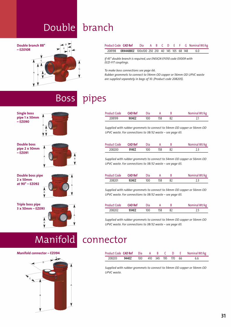
Product Code CAD Ref Dia A B C D E NominalWt/kg208203 944EZ 100 410 345 195 170 66 6.6
Supplied with rubber grommets to connect to 54mm OD copper or 56mm ODUPVC waste.
B
A
C
D
B
Manifold connector
Boss pipesSingle bosspipe 1 x 50mm– EZ090
Manifold connector – EZ094
Product Code CAD Ref Dia A B C D E F G NominalWt/kg208198 0R44488EZ 100x100 250 210 40 145 105 68 148 6.0
If 45° double branch is required, use ENSIGN EF010 code 03009 withEEZI-FIT couplings.
To make boss connections see page 66.Rubber grommets to connect to 54mm OD copper or 56mm OD UPVC wasteare supplied separately in bags of 10. (Product code 208205).
G
C
D
E
A
C
B F
E
Double branch 88°– EZ010R
Roof outlets for asphalt or felt
32
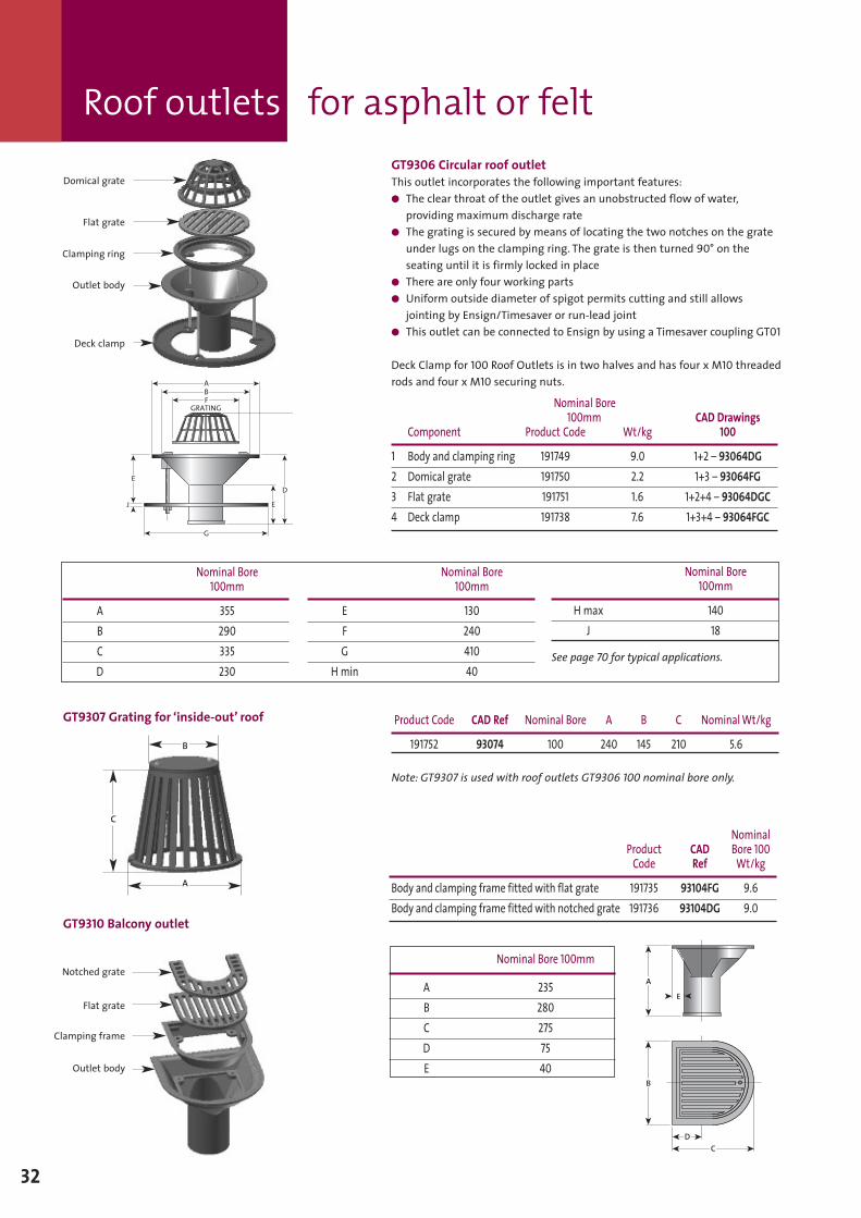
GT9306 Circular roof outletThis outlet incorporates the following important features:� The clear throat of the outlet gives an unobstructed flow of water,
providing maximum discharge rate� The grating is secured by means of locating the two notches on the grate
under lugs on the clamping ring. The grate is then turned 90° on theseating until it is firmly locked in place
� There are only four working parts� Uniform outside diameter of spigot permits cutting and still allows
jointing by Ensign/Timesaver or run-lead joint� This outlet can be connected to Ensign by using a Timesaver coupling GT01
Deck Clamp for 100 Roof Outlets is in two halves and has four xM10 threadedrods and four xM10 securing nuts.
Nominal Bore100mm CAD Drawings
Component Product Code Wt/kg 100
1 Body and clamping ring 191749 9.0 1+2 – 93064DG2 Domical grate 191750 2.2 1+3 – 93064FG3 Flat grate 191751 1.6 1+2+4 – 93064DGC4 Deck clamp 191738 7.6 1+3+4 – 93064FGC
Nominal Bore100mm
Hmax 140J 18
See page 70 for typical applications.
Nominal Bore100mm
E 130F 240G 410
Hmin 40
Domical grate
Flat grate
Clamping ring
Outlet body
Deck clamp
E
G
E
D
ABF
GRATING
J
GT9307 Grating for ‘inside-out’ roof Product Code CAD Ref Nominal Bore A B C NominalWt/kg
191752 93074 100 240 145 210 5.6
Note: GT9307 is used with roof outlets GT9306 100 nominal bore only.
GT9310 Balcony outlet
NominalProduct CAD Bore 100Code Ref Wt/kg
Body and clamping frame fitted with flat grate 191735 93104FG 9.6Body and clamping frame fitted with notched grate 191736 93104DG 9.0
Nominal Bore 100mm
A 235B 280C 275D 75E 40
B
A
C
Outlet body
Notched grate
Flat grate
Clamping frame
C
D
A
E
B
Nominal Bore100mm
A 355B 290C 335D 230
Pipes and Fittings– below ground
Sect
ion2
33
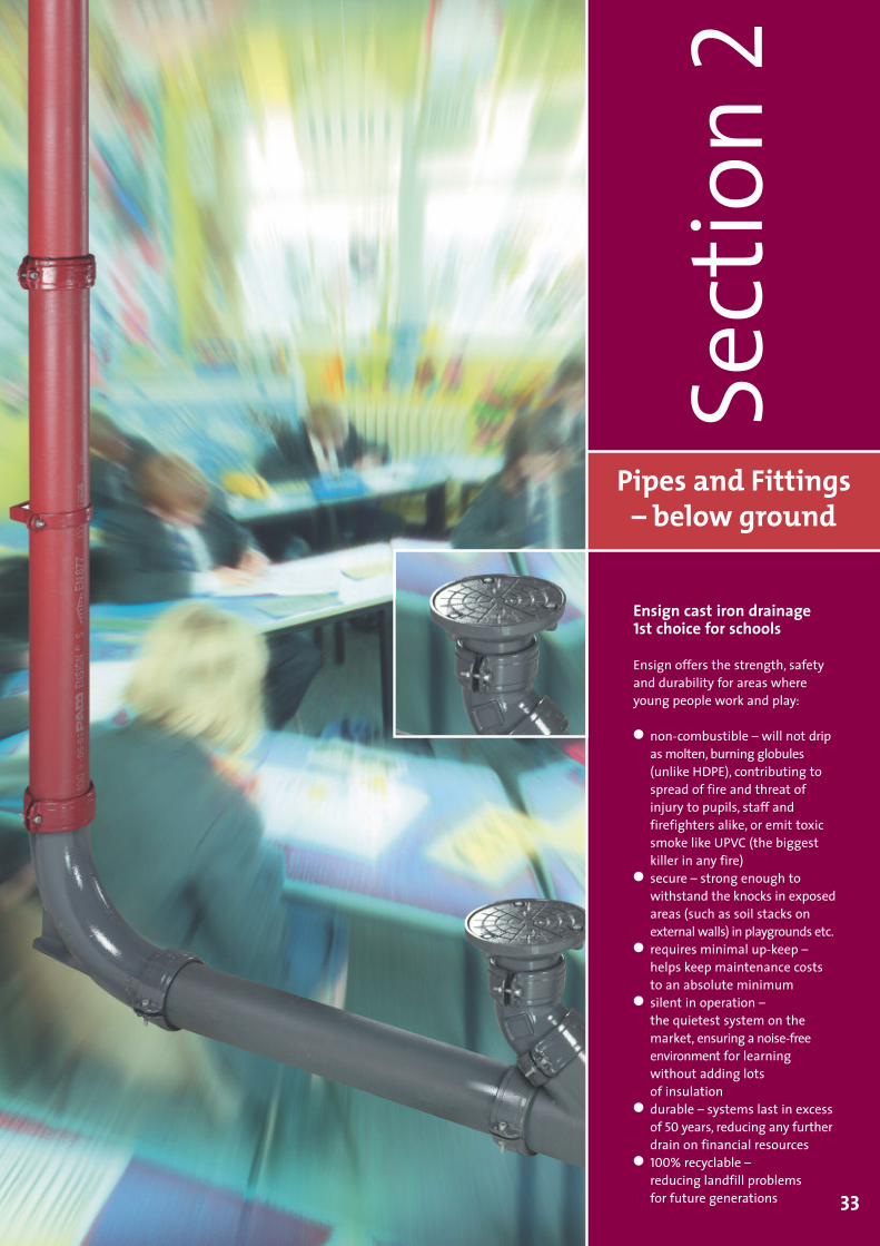
Ensign cast iron drainage1st choice for schools
Ensign offers the strength, safetyand durability for areas whereyoung people work and play:
� non-combustible – will not dripasmolten, burning globules(unlike HDPE), contributing tospread of fire and threat ofinjury to pupils, staff andfirefighters alike, or emit toxicsmoke like UPVC (the biggestkiller in any fire)
� secure – strong enough towithstand the knocks in exposedareas (such as soil stacks onexternal walls) in playgrounds etc.
� requires minimal up-keep –helps keep maintenance coststo an absolute minimum
� silent in operation –the quietest system on themarket, ensuring a noise-freeenvironment for learningwithout adding lotsof insulation
� durable – systems last in excessof 50 years, reducing any furtherdrain on financial resources
� 100% recyclable –reducing landfill problemsfor future generations
Pipes double spigot
Couplings
34
BA
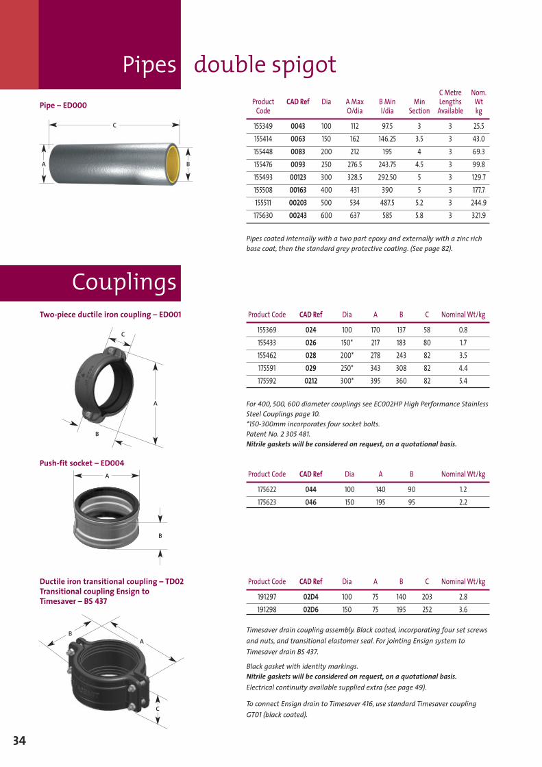
Pipe – ED000CMetre Nom.
Product CAD Ref Dia A Max B Min Min Lengths WtCode O/dia I/dia Section Available kg
155349 0043 100 112 97.5 3 3 25.5155414 0063 150 162 146.25 3.5 3 43.0155448 0083 200 212 195 4 3 69.3155476 0093 250 276.5 243.75 4.5 3 99.8155493 00123 300 328.5 292.50 5 3 129.7155508 00163 400 431 390 5 3 177.7155511 00203 500 534 487.5 5.2 3 244.9
175630 00243 600 637 585 5.8 3 321.9
Pipes coated internally with a two part epoxy and externally with a zinc richbase coat, then the standard grey protective coating. (See page 82).
Two-piece ductile iron coupling – ED001 Product Code CAD Ref Dia A B C NominalWt/kg
155369 024 100 170 137 58 0.8155433 026 150* 217 183 80 1.7155462 028 200* 278 243 82 3.5175591 029 250* 343 308 82 4.4175592 0212 300* 395 360 82 5.4
For 400, 500, 600 diameter couplings see EC002HP High Performance StainlessSteel Couplings page 10.*150-300mm incorporates four socket bolts.Patent No. 2 305 481.Nitrile gaskets will be considered on request, on a quotational basis.
Push-fit socket – ED004Product Code CAD Ref Dia A B NominalWt/kg
175622 044 100 140 90 1.2175623 046 150 195 95 2.2
B
C
A
A
B
C
Ductile iron transitional coupling – TD02Transitional coupling Ensign toTimesaver – BS 437
Product Code CAD Ref Dia A B C NominalWt/kg
191297 02D4 100 75 140 203 2.8191298 02D6 150 75 195 252 3.6
Timesaver drain coupling assembly. Black coated, incorporating four set screwsand nuts, and transitional elastomer seal. For jointing Ensign system toTimesaver drain BS 437.
Black gasket with identity markings.Nitrile gaskets will be considered on request, on a quotational basis.Electrical continuity available supplied extra (see page 49).
To connect Ensign drain to Timesaver 416, use standard Timesaver couplingGT01 (black coated).
A
C
B
Brackets
35
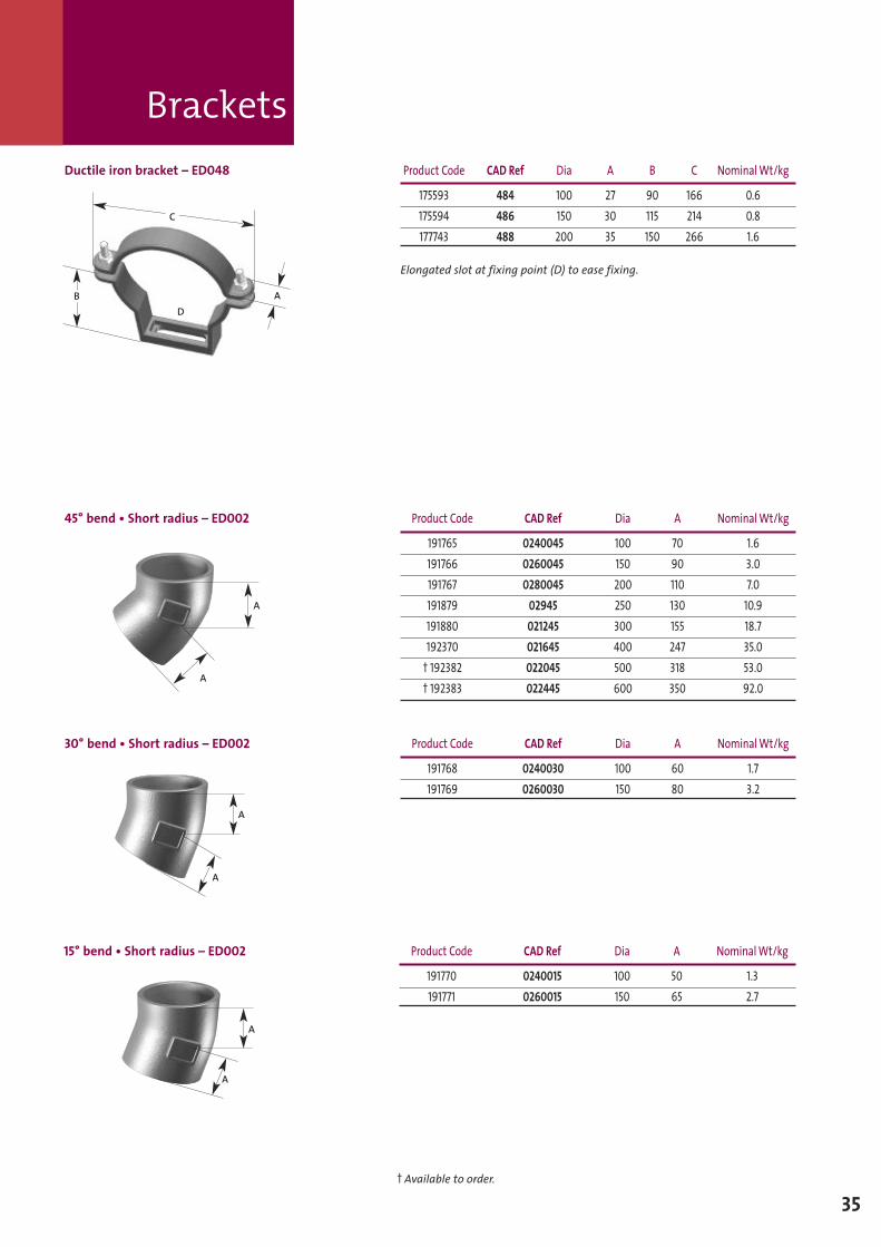
Ductile iron bracket – ED048 Product Code CAD Ref Dia A B C NominalWt/kg
175593 484 100 27 90 166 0.6175594 486 150 30 115 214 0.8177743 488 200 35 150 266 1.6
Elongated slot at fixing point (D) to ease fixing.
45° bend • Short radius – ED002 Product Code CAD Ref Dia A NominalWt/kg
191765 0240045 100 70 1.6191766 0260045 150 90 3.0191767 0280045 200 110 7.0191879 02945 250 130 10.9191880 021245 300 155 18.7192370 021645 400 247 35.0
† 192382 022045 500 318 53.0† 192383 022445 600 350 92.0
30° bend • Short radius – ED002 Product Code CAD Ref Dia A NominalWt/kg
191768 0240030 100 60 1.7191769 0260030 150 80 3.2
A
A
A
A
AB
C
D
15° bend • Short radius – ED002 Product Code CAD Ref Dia A NominalWt/kg
191770 0240015 100 50 1.3191771 0260015 150 65 2.7
A
A
† Available to order.
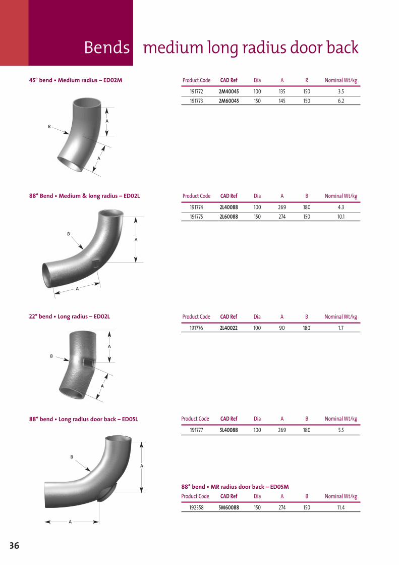
88° bend • Long radius door back – ED05L Product Code CAD Ref Dia A B NominalWt/kg
191777 5L40088 100 269 180 5.5
88° bend • MR radius door back – ED05MProduct Code CAD Ref Dia A B NominalWt/kg
192358 5M60088 150 274 150 11.4
A
A
B
Bends medium long radius door back
36
45° bend • Medium radius – ED02M Product Code CAD Ref Dia A R NominalWt/kg
191772 2M40045 100 135 150 3.5191773 2M60045 150 145 150 6.2
88° Bend • Medium & long radius – ED02L Product Code CAD Ref Dia A B NominalWt/kg
191774 2L40088 100 269 180 4.3191775 2L60088 150 274 150 10.1
A
A
B
RA
A
22° bend • Long radius – ED02L Product Code CAD Ref Dia A B NominalWt/kg
191776 2L40022 100 90 180 1.7
A
A
B
Bends medium long radius door back
37
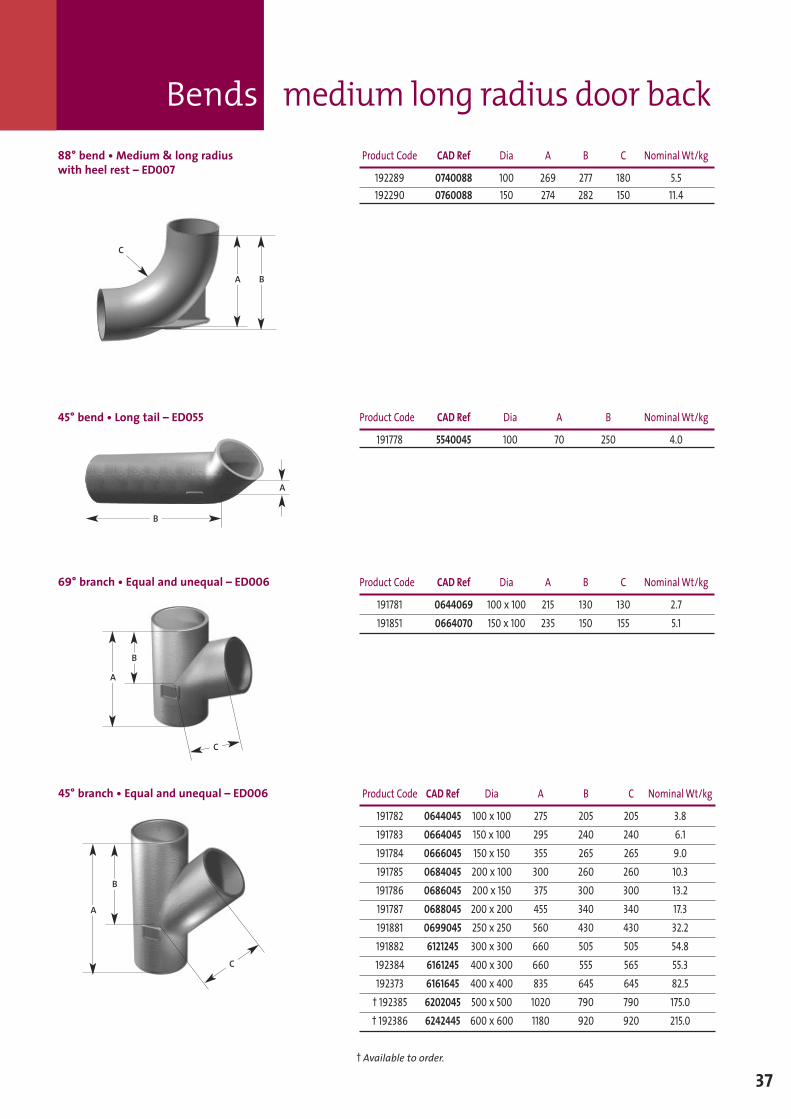
69° branch • Equal and unequal – ED006 Product Code CAD Ref Dia A B C NominalWt/kg
191781 0644069 100 x 100 215 130 130 2.7191851 0664070 150 x 100 235 150 155 5.1
45° bend • Long tail – ED055 Product Code CAD Ref Dia A B NominalWt/kg
191778 5540045 100 70 250 4.0
B
A
A
B
C
45° branch • Equal and unequal – ED006 Product Code CAD Ref Dia A B C NominalWt/kg
191782 0644045 100 x 100 275 205 205 3.8191783 0664045 150 x 100 295 240 240 6.1191784 0666045 150 x 150 355 265 265 9.0191785 0684045 200 x 100 300 260 260 10.3191786 0686045 200 x 150 375 300 300 13.2191787 0688045 200 x 200 455 340 340 17.3191881 0699045 250 x 250 560 430 430 32.2191882 6121245 300 x 300 660 505 505 54.8192384 6161245 400 x 300 660 555 565 55.3192373 6161645 400 x 400 835 645 645 82.5
† 192385 6202045 500 x 500 1020 790 790 175.0† 192386 6242445 600 x 600 1180 920 920 215.0
A
B
C
88° bend • Medium & long radiuswith heel rest – ED007
Product Code CAD Ref Dia A B C NominalWt/kg
192289 0740088 100 269 277 180 5.5192290 0760088 150 274 282 150 11.4
BA
C
† Available to order.
Branches
38
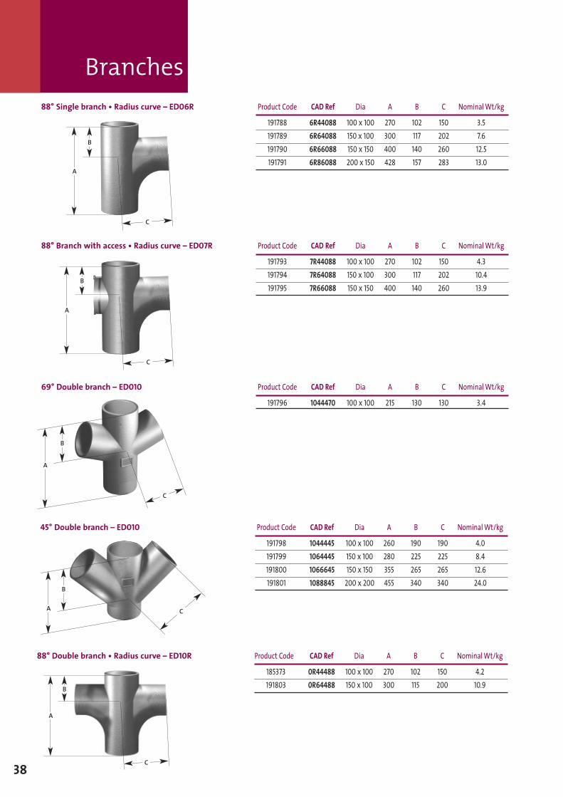
88° Single branch • Radius curve – ED06R Product Code CAD Ref Dia A B C NominalWt/kg
191788 6R44088 100 x 100 270 102 150 3.5191789 6R64088 150 x 100 300 117 202 7.6191790 6R66088 150 x 150 400 140 260 12.5191791 6R86088 200 x 150 428 157 283 13.0
A
B
88° Branch with access • Radius curve – ED07R Product Code CAD Ref Dia A B C NominalWt/kg
191793 7R44088 100 x 100 270 102 150 4.3191794 7R64088 150 x 100 300 117 202 10.4191795 7R66088 150 x 150 400 140 260 13.9
A
B
C
C
69° Double branch – ED010 Product Code CAD Ref Dia A B C NominalWt/kg
191796 1044470 100 x 100 215 130 130 3.4
A
B
C
45° Double branch – ED010 Product Code CAD Ref Dia A B C NominalWt/kg
191798 1044445 100 x 100 260 190 190 4.0191799 1064445 150 x 100 280 225 225 8.4191800 1066645 150 x 150 355 265 265 12.6191801 1088845 200 x 200 455 340 340 24.0
88° Double branch • Radius curve – ED10R Product Code CAD Ref Dia A B C NominalWt/kg
185373 0R44488 100 x 100 270 102 150 4.2191803 0R64488 150 x 100 300 115 200 10.9
A
B
C
A
B
C
Pipes tapered
Pipes access
39
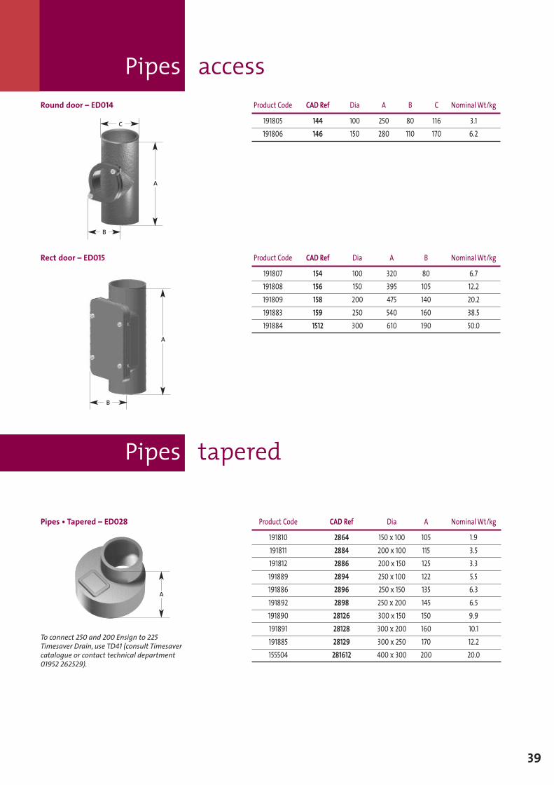
Round door – ED014 Product Code CAD Ref Dia A B C NominalWt/kg
191805 144 100 250 80 116 3.1191806 146 150 280 110 170 6.2
Rect door – ED015 Product Code CAD Ref Dia A B NominalWt/kg
191807 154 100 320 80 6.7191808 156 150 395 105 12.2191809 158 200 475 140 20.2191883 159 250 540 160 38.5191884 1512 300 610 190 50.0
A
C
A
B
B
Pipes • Tapered – ED028 Product Code CAD Ref Dia A NominalWt/kg
191810 2864 150 x 100 105 1.9191811 2884 200 x 100 115 3.5191812 2886 200 x 150 125 3.3191889 2894 250 x 100 122 5.5191886 2896 250 x 150 135 6.3191892 2898 250 x 200 145 6.5191890 28126 300 x 150 150 9.9191891 28128 300 x 200 160 10.1191885 28129 300 x 250 170 12.2155504 281612 400 x 300 200 20.0
A
To connect 250 and 200 Ensign to 225Timesaver Drain, use TD41 (consult Timesavercatalogue or contact technical department01952 262529).
Pipes and connectors transitional
Traps
Blank ends
40
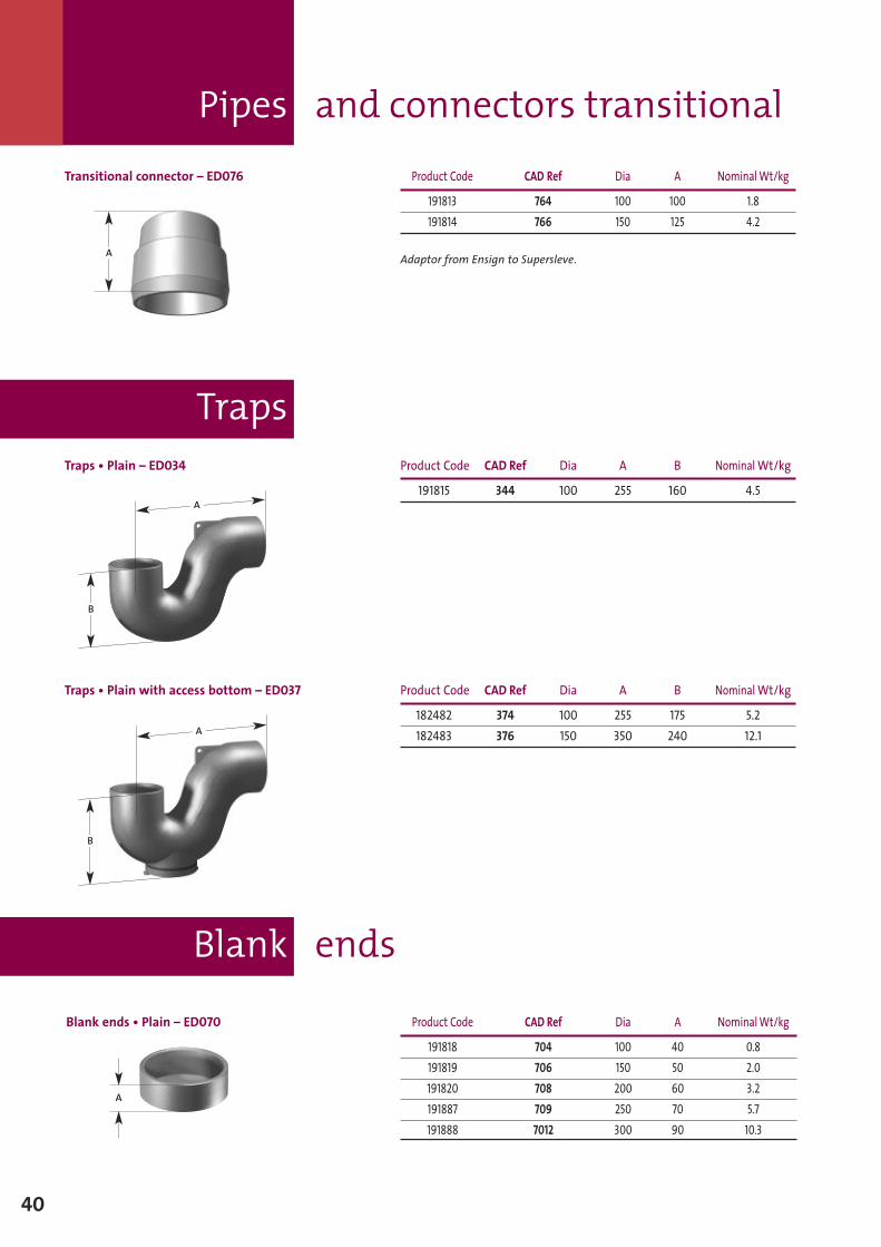
Transitional connector – ED076 Product Code CAD Ref Dia A NominalWt/kg
191813 764 100 100 1.8191814 766 150 125 4.2
Adaptor from Ensign to Supersleve.A
Traps • Plain – ED034 Product Code CAD Ref Dia A B NominalWt/kg
191815 344 100 255 160 4.5
Traps • Plain with access bottom – ED037 Product Code CAD Ref Dia A B NominalWt/kg
182482 374 100 255 175 5.2182483 376 150 350 240 12.1
B
A
B
A
Blank ends • Plain – ED070 Product Code CAD Ref Dia A NominalWt/kg
191818 704 100 40 0.8191819 706 150 50 2.0191820 708 200 60 3.2191887 709 250 70 5.7191888 7012 300 90 10.3
A
Blank ends
41
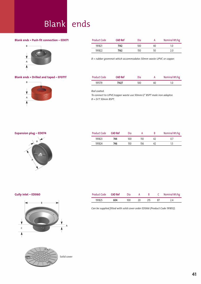
Blank ends • Push-fit connection – ED071 Product Code CAD Ref Dia A NominalWt/kg
191821 7142 100 40 1.0191822 7162 150 50 2.0
B = rubber grommet which accommodates 50mm waste UPVC or copper.
Expansion plug – ED074 Product Code CAD Ref Dia A B NominalWt/kg
191823 744 100 110 42 0.7191824 746 150 156 42 1.5
A
B
Gully inlet – ED060 Product Code CAD Ref Dia A B C NominalWt/kg
191825 604 100 20 215 87 2.4
Can be supplied fitted with solid cover order ED066 (Product Code 191852).
A
B
C
Solid cover
Blank ends • Drilled and taped – EF071T Product Code CAD Ref Dia A NominalWt/kg
191579 7142T 100 40 1.0
Red coated.To connect to UPVC/copper waste use 50mm/2" BSPT male iron adaptor.B = D/T 50mm BSPT.A
B
A
B
Gully inlet Bellmouth
Puddle flanges
42
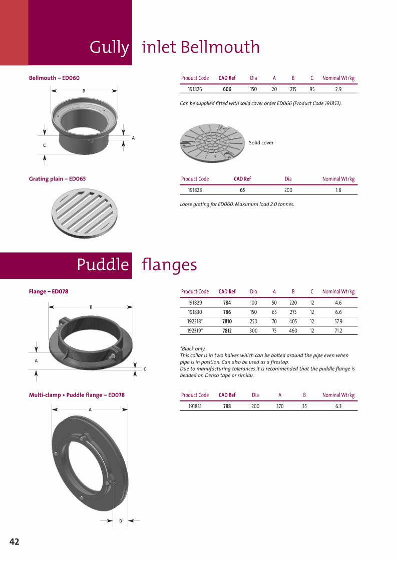
Bellmouth – ED060 Product Code CAD Ref Dia A B C NominalWt/kg
191826 606 150 20 215 95 2.9
Can be supplied fitted with solid cover order ED066 (Product Code 191853).
Grating plain – ED065 Product Code CAD Ref Dia NominalWt/kg
191828 65 200 1.8
Loose grating for ED060.Maximum load 2.0 tonnes.
Flange – ED078 Product Code CAD Ref Dia A B C NominalWt/kg
191829 784 100 50 220 12 4.6191830 786 150 65 275 12 6.6192318* 7810 250 70 405 12 57.9192319* 7812 300 75 460 12 71.2
*Black only.This collar is in two halves which can be bolted around the pipe even whenpipe is in position. Can also be used as a firestop.Due to manufacturing tolerances it is recommended that the puddle flange isbedded on Denso tape or similar.
Multi-clamp • Puddle flange – ED078 Product Code CAD Ref Dia A B NominalWt/kg
191831 788 200 370 35 6.3
A
B
C Solid cover
B
C
A
B
A
Floor drains adjustable
Inspection chambers
43
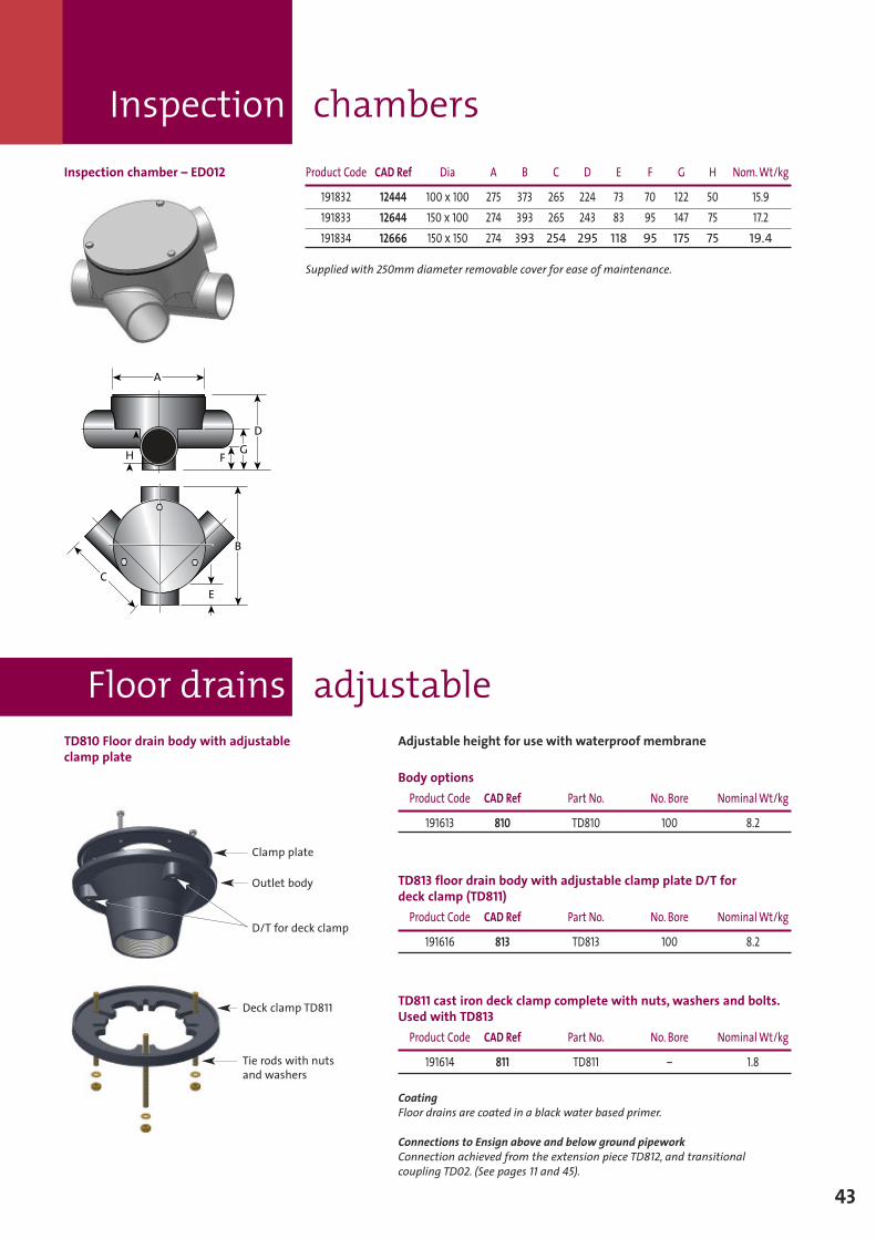
TD810 Floor drain body with adjustableclamp plate
TD813 floor drain body with adjustable clamp plate D/T fordeck clamp (TD811)
Product Code CAD Ref Part No. No. Bore NominalWt/kg
191616 813 TD813 100 8.2
TD811 cast iron deck clamp complete with nuts, washers and bolts.Used with TD813
Product Code CAD Ref Part No. No. Bore NominalWt/kg
191614 811 TD811 – 1.8
CoatingFloor drains are coated in a black water based primer.
Connections to Ensign above and below ground pipeworkConnection achieved from the extension piece TD812, and transitionalcoupling TD02. (See pages 11 and 45).
Adjustable height for use with waterproof membrane
Body optionsProduct Code CAD Ref Part No. No. Bore NominalWt/kg
191613 810 TD810 100 8.2
Inspection chamber – ED012 Product Code CAD Ref Dia A B C D E F G H Nom.Wt/kg
191832 12444 100 x 100 275 373 265 224 73 70 122 50 15.9191833 12644 150 x 100 274 393 265 243 83 95 147 75 17.2191834 12666 150 x 150 274 393 254 295 118 95 175 75 19.4
Supplied with 250mm diameter removable cover for ease of maintenance.
Clamp plate
Outlet body
D/T for deck clamp
Deck clamp TD811
Tie rods with nutsand washers
ä
ä
Dä
ä
Gä
äF
ä
ä
B
ä
äE
ä
ä
C
ä
äA
H
ä
ä
Floor drains adjustable
44
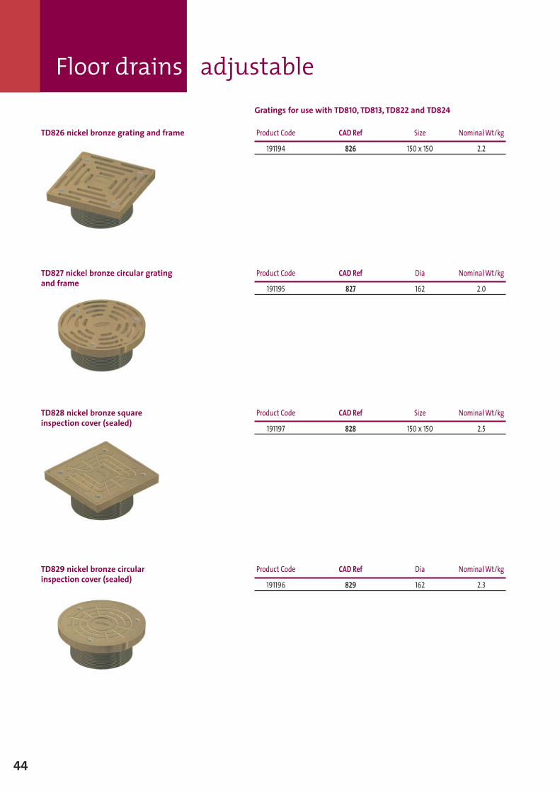
TD828 nickel bronze squareinspection cover (sealed)
Product Code CAD Ref Size NominalWt/kg
191197 828 150 x 150 2.5
TD829 nickel bronze circularinspection cover (sealed)
Product Code CAD Ref Dia NominalWt/kg
191196 829 162 2.3
Gratings for use with TD810, TD813, TD822 and TD824
TD826 nickel bronze grating and frame Product Code CAD Ref Size NominalWt/kg
191194 826 150 x 150 2.2
TD827 nickel bronze circular gratingand frame
Product Code CAD Ref Dia NominalWt/kg
191195 827 162 2.0
Floor drains adjustable
45
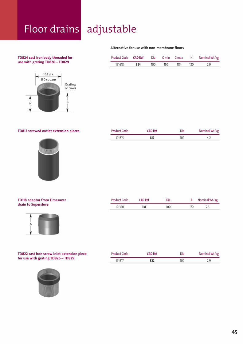
TD812 screwed outlet extension pieces Product Code CAD Ref Dia NominalWt/kg
191615 812 100 4.2
TD118 adaptor from Timesaverdrain to Supersleve
Product Code CAD Ref Dia A NominalWt/kg
191350 118 100 170 2.3
TD822 cast iron screw inlet extension piecefor use with grating TD826 – TD829
Product Code CAD Ref Dia NominalWt/kg
191617 822 100 2.9
Alternative for use with non-membrane floors
TD824 cast iron body threaded foruse with grating TD826 – TD829
Product Code CAD Ref Dia G min G max H NominalWt/kg
191618 824 100 150 175 120 2.9
Gratingor cover
162 dia150 square
H G
A
Floor drains technical
46
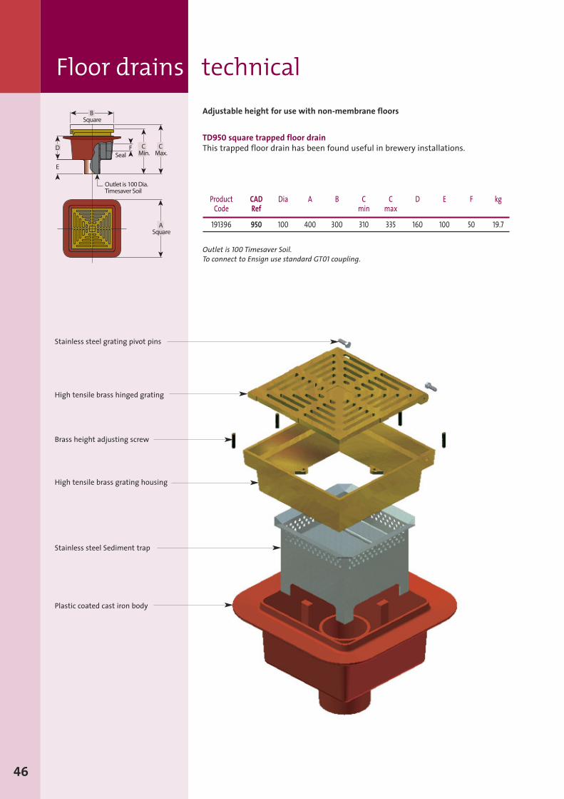
Adjustable height for use with non-membrane floors
TD950 square trapped floor drainThis trapped floor drain has been found useful in brewery installations.
Product CAD Dia A B C C D E F kgCode Ref min max
191396 950 100 400 300 310 335 160 100 50 19.7
Outlet is 100 Timesaver Soil.To connect to Ensign use standard GT01 coupling.
Stainless steel grating pivot pins
High tensile brass hinged grating
Brass height adjusting screw
High tensile brass grating housing
Stainless steel Sediment trap
Plastic coated cast iron body
Couplings– technical
Sect
ion3
47
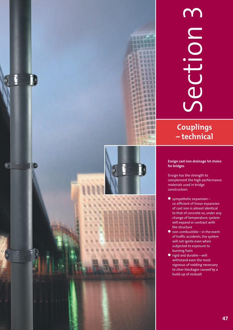
Ensign cast iron drainage 1st choicefor bridges
Ensign has the strength tocomplement the high-performancematerials used in bridgeconstruction:
� sympathetic expansion –co-efficient of linear expansionof cast iron is almost identicalto that of concrete so, under anychange of temperature, systemwill expand or contract withthe structure
� non-combustible – in the eventof traffic accidents, the systemwill not ignite even whensubjected to exposure toburning fuels
� rigid and durable – willwithstand even the mostvigorous of rodding necessaryto clear blockages caused by abuild-up of rocksalt
SGPL 116359 Ensign Manual Sect 3 and 4 2009 V6 MH:Layout 1 17/7/09 12:39 Page 47
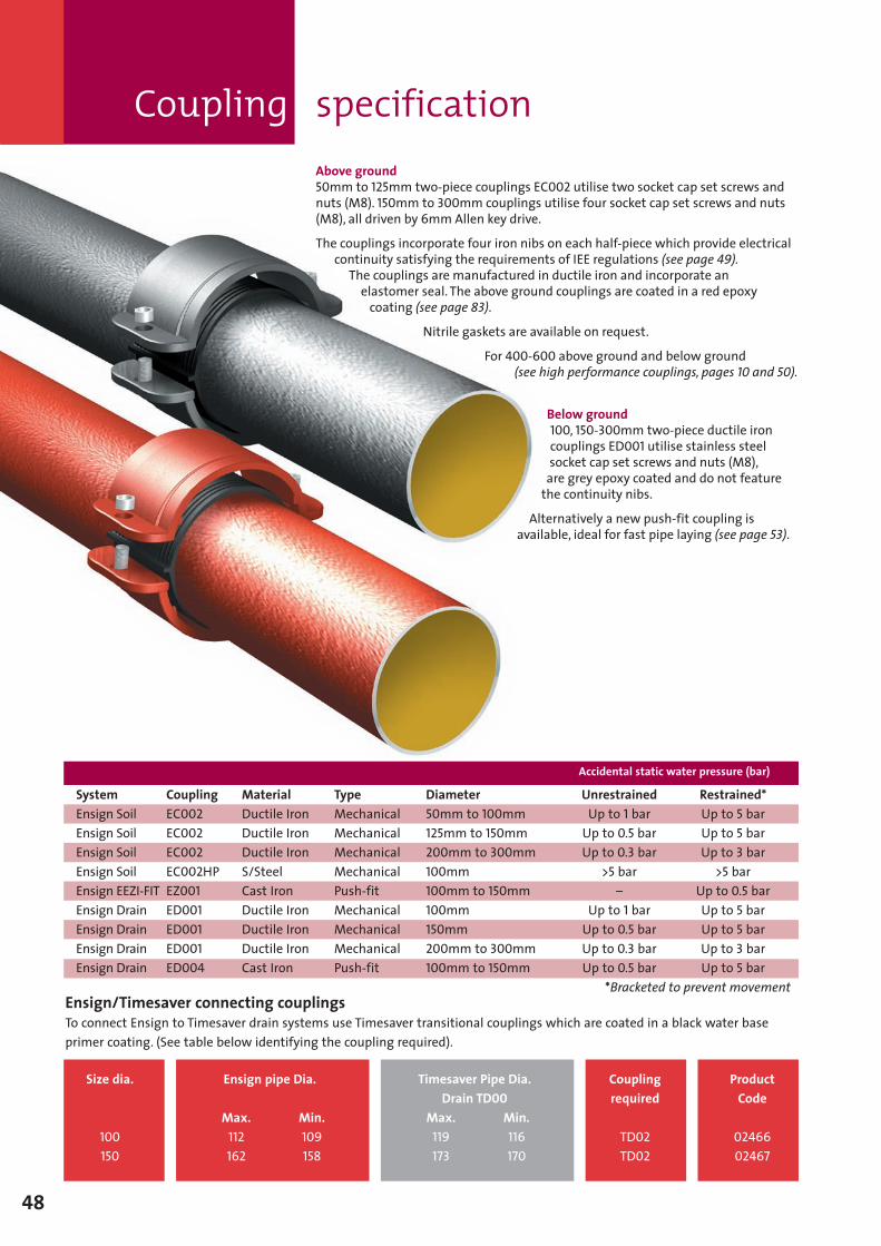
Above ground50mm to 125mm two-piece couplings EC002 utilise two socket cap set screws andnuts (M8). 150mm to 300mm couplings utilise four socket cap set screws and nuts(M8), all driven by 6mm Allen key drive.
The couplings incorporate four iron nibs on each half-piece which provide electricalcontinuity satisfying the requirements of IEE regulations (see page 49).The couplings are manufactured in ductile iron and incorporate anelastomer seal. The above ground couplings are coated in a red epoxycoating (see page 83).
Nitrile gaskets are available on request.
For 400-600 above ground and below ground(see high performance couplings, pages 10 and 50).
Below ground100, 150-300mm two-piece ductile ironcouplings ED001 utilise stainless steelsocket cap set screws and nuts (M8),are grey epoxy coated and do not featurethe continuity nibs.
Alternatively a new push-fit coupling isavailable, ideal for fast pipe laying (see page 53).
Coupling specification
48
Size dia.
100150
Couplingrequired
TD02TD02
ProductCode
0246602467
Ensign pipe Dia.
Max. Min.112 109162 158
Timesaver Pipe Dia.Drain TD00
Max. Min.119 116173 170
Ensign/Timesaver connecting couplingsTo connect Ensign to Timesaver drain systems use Timesaver transitional couplings which are coated in a black water baseprimer coating. (See table below identifying the coupling required).
Accidental static water pressure (bar)
System Coupling Material Type Diameter Unrestrained Restrained*Ensign Soil EC002 Ductile Iron Mechanical 50mm to 100mm Up to 1 bar Up to 5 barEnsign Soil EC002 Ductile Iron Mechanical 125mm to 150mm Up to 0.5 bar Up to 5 barEnsign Soil EC002 Ductile Iron Mechanical 200mm to 300mm Up to 0.3 bar Up to 3 barEnsign Soil EC002HP S/Steel Mechanical 100mm >5 bar >5 barEnsign EEZI-FIT EZ001 Cast Iron Push-fit 100mm to 150mm – Up to 0.5 barEnsign Drain ED001 Ductile Iron Mechanical 100mm Up to 1 bar Up to 5 barEnsign Drain ED001 Ductile Iron Mechanical 150mm Up to 0.5 bar Up to 5 barEnsign Drain ED001 Ductile Iron Mechanical 200mm to 300mm Up to 0.3 bar Up to 3 barEnsign Drain ED004 Cast Iron Push-fit 100mm to 150mm Up to 0.5 bar Up to 5 bar
*Bracketed to prevent movement
SGPL 116359 Ensign Manual Sect 3 and 4 2009 V6 MH:Layout 1 17/7/09 12:39 Page 48
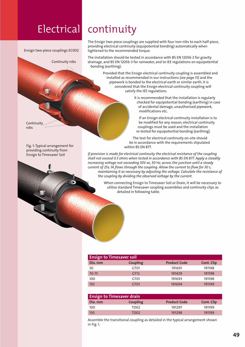
Electrical continuityThe Ensign two-piece couplings are supplied with four iron nibs to each half-piece,providing electrical continuity (equipotential bonding) automatically whentightened to the recommended torque.
The installation should be tested in accordance with BS EN 12056-2 for gravitydrainage, and BS EN 12056-3 for rainwater, and to IEE regulations on equipotentialbonding (earthing).
Provided that the Ensign electrical continuity coupling is assembled andinstalled as recommended in our instructions (see page 51) and thepipework is bonded to the electrical earth or similar earth, it is
considered that the Ensign electrical continuity coupling willsatisfy the IEE regulations.
It is recommended that the installation is regularlychecked for equipotential bonding (earthing) in caseof accidental damage, unauthorised pipework,modifications etc.
If an Ensign electrical continuity installation is tobe modified for any reason, electrical continuitycouplings must be used and the installationre-tested for equipotential bonding (earthing).
The test for electrical continuity on-site shouldbe in accordance with the requirements stipulated
within BS EN 877.
If provision is made for electrical continuity the electrical resistance of the couplingshall not exceed 0.3 ohms when tested in accordance with BS EN 877. Apply a steadilyincreasing voltage not exceeding 50V ac, 50 Hz, across the junction until a steadycurrent of 25± 1A flows through the coupling. Allow the current to flow for 30 s,
maintaining it as necessary by adjusting the voltage. Calculate the resistance ofthe coupling by dividing the observed voltage by the current.
When connecting Ensign to Timesaver Soil or Drain, it will be necessary toutilise standard Timesaver coupling assemblies and continuity clips as
detailed in following table.
49
Assemble the transitional coupling as detailed in the typical arrangement shownin Fig. 1.
Fig. 1: Typical arrangement forproviding continuity fromEnsign to Timesaver Soil
Ensign two-piece couplings EC002
Continuity nibs
Continuitynibs
Ensign to Timesaver soilDia. mm Coupling Product Code Cont. Clip50 GT01 191691 19119870-75 GT12 191429 191198100 GT01 191693 191198150 GT01 191694 191199
Ensign to Timesaver drainDia. mm Coupling Product Code Cont. Clip100 TD02 191297 191199150 TD02 191298 191199
SGPL 116359 Ensign Manual Sect 3 and 4 2009 V6 MH:Layout 1 17/7/09 12:39 Page 49
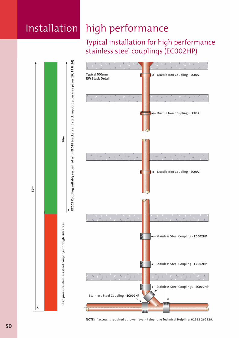
Installation high performance
50
Ductile Iron Coupling - EC002ä
Stainless Steel Coupling - EC002HPä
Ductile Iron Coupling - EC002ä
Ductile Iron Coupling - EC002ä
Stainless Steel Coupling - EC002HPä
Stainless Steel Couplings - EC002HPä
ä
äStainless Steel Coupling - EC002HP
ä
ä
ä
ää
EC0
02
Co
up
lin
gsu
itab
lyre
stra
ined
wit
hEF
04
8b
rack
ets
and
stac
ksu
pp
ort
pip
es(s
eep
ages
10
,13
&2
6)
50
m
30
mH
igh
pre
ssu
rest
ain
less
stee
lco
up
lin
gs
for
hig
hri
skar
eas
NOTE: If access is required at lower level - telephone Technical Helpline: 01952 262529.
Typical 100mmRW Stack Detail
Typical installation for high performancestainless steel couplings (EC002HP)
SGPL 116359 Ensign Manual Sect 3 and 4 2009 V6 MH:Layout 1 17/7/09 12:39 Page 50

Tools
Jointing method
51
Couplings are suppliedpre-assembled.1. Slacken bolts on coupling tofullest extent, removing the bolt(s)from one side to ease assembly andremove rubber gasket.
2. Place the rubber gasket over theend of the pipe or fitting, ensuringthe central register is abuttedagainst the spigot edge.
A
C
B
D E F
3. Push the second pipe or fittinginto the gasket again ensuring thatthe spigot is abutted against thecentral register.
4. Loosely assemble the couplingaround the gasket.
1
2
5. Check alignment of assemblybefore tightening the bolts.Coupling bolts on all sizes are M8and require special Allen socketadaptor (6mm) EF102, togetherwith a ratchet spanner EF100.
Note: Bolts should be tightened untila suitable resistance is achieved ifusing a torque wrench minimumsetting 20Nm.
3
4
5
Product Code
A – Ensign EC Lube (1 litre bottle) EC0931 191171For use with all push-fit connections
B – Lubricant for EEZI-FIT push-fit assembly joints (0.5 litre tub) 199037
C – 1/2" Square-drive EF100 191201Ratchet Spanner (use with C and E)For use with nuts on fixing brackets and on access doorfittings and also with new two-piece coupling
D – 13mmA/F 1/2" Square-drive EF101 191202Deep Socket (use with ratchet B)For use with nuts on fixing brackets and on access door fittings
E – 13mmA/F ‘T’ Box Spanner EF098 191200For use with nuts on fixing brackets and on access door fittings
F – 6mm Allen Socket Adaptor (use with ratchet B) EF102 191753For use with bolts on all ductile iron couplings
SGPL 116359 Ensign Manual Sect 3 and 4 2009 V6 MH:Layout 1 17/7/09 12:39 Page 51
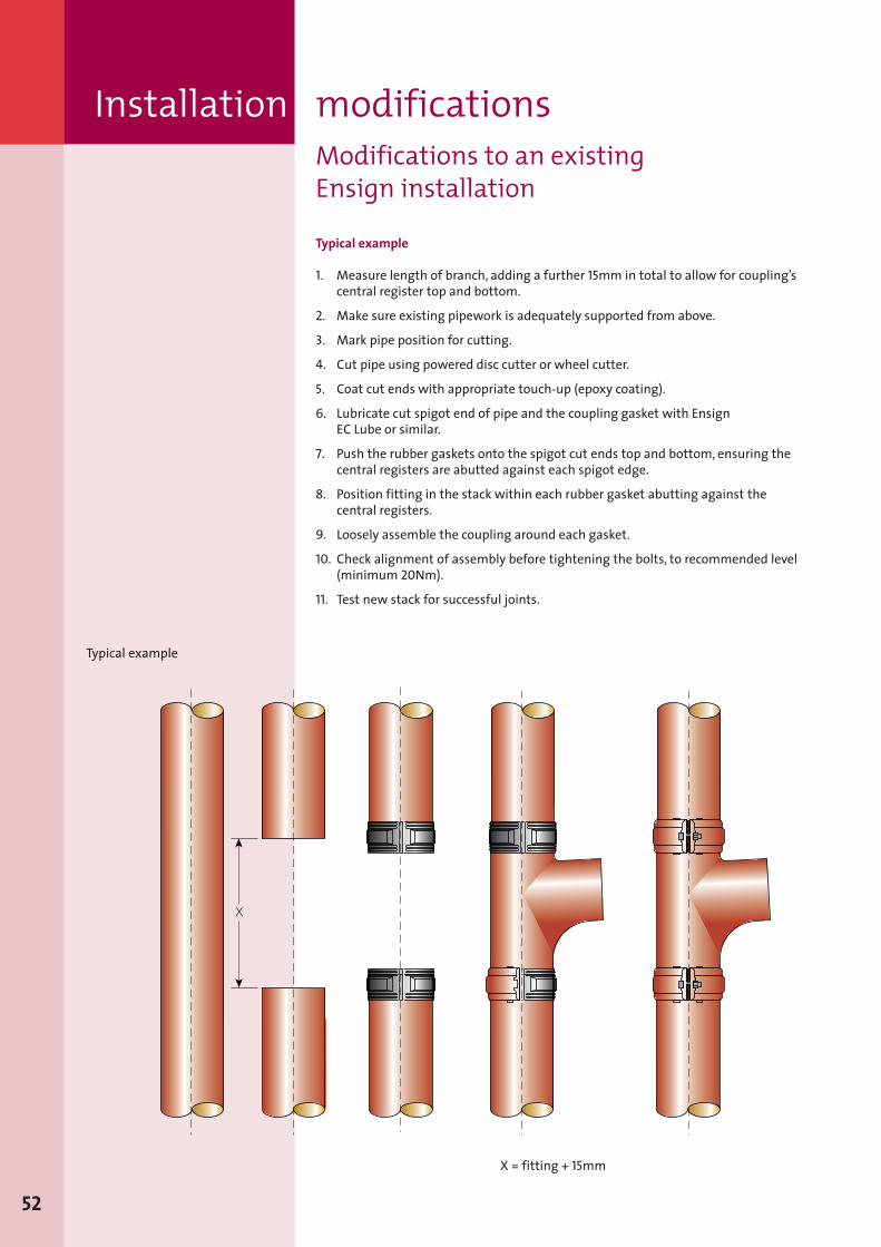
Installation modificationsModifications to an existingEnsign installation
Typical example
1. Measure length of branch, adding a further 15mm in total to allow for coupling’scentral register top and bottom.
2. Make sure existing pipework is adequately supported from above.
3. Mark pipe position for cutting.
4. Cut pipe using powered disc cutter or wheel cutter.
5. Coat cut ends with appropriate touch-up (epoxy coating).
6. Lubricate cut spigot end of pipe and the coupling gasket with EnsignEC Lube or similar.
7. Push the rubber gaskets onto the spigot cut ends top and bottom, ensuring thecentral registers are abutted against each spigot edge.
8. Position fitting in the stack within each rubber gasket abutting against thecentral registers.
9. Loosely assemble the coupling around each gasket.
10. Check alignment of assembly before tightening the bolts, to recommended level(minimum 20Nm).
11. Test new stack for successful joints.
ä
ä
X
Typical example
X = fitting + 15mm
52
SGPL 116359 Ensign Manual Sect 3 and 4 2009 V6 MH:Layout 1 17/7/09 12:39 Page 52
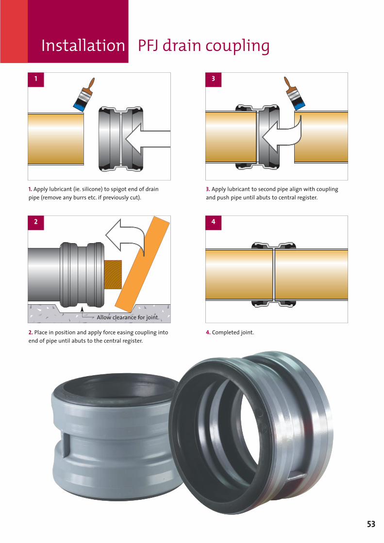
1. Apply lubricant (ie. silicone) to spigot end of drainpipe (remove any burrs etc. if previously cut).
2. Place in position and apply force easing coupling intoend of pipe until abuts to the central register.
3. Apply lubricant to second pipe align with couplingand push pipe until abuts to central register.
4. Completed joint.
1 3
42
Allow clearance for joint.
Installation PFJ drain coupling
53
SGPL 116359 Ensign Manual Sect 3 and 4 2009 V6 MH:Layout 1 17/7/09 12:39 Page 53
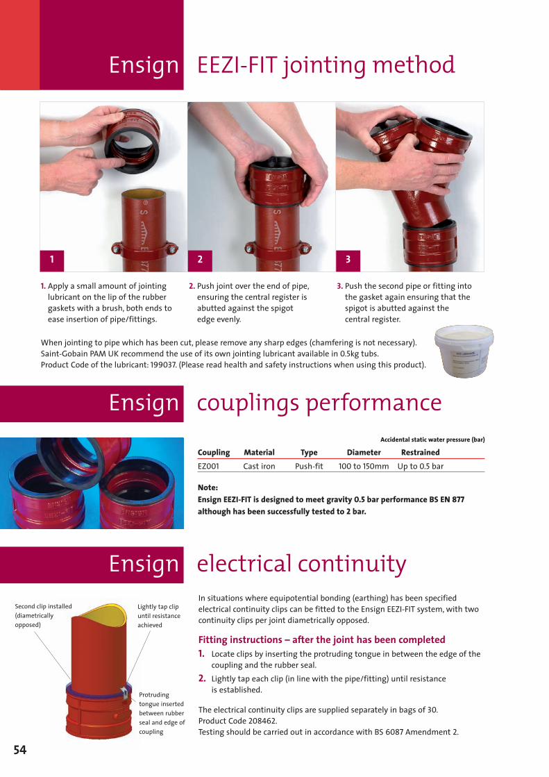
Ensign EEZI-FIT jointing method
54
1. Apply a small amount of jointinglubricant on the lip of the rubbergaskets with a brush, both ends toease insertion of pipe/fittings.
2. Push joint over the end of pipe,ensuring the central register isabutted against the spigotedge evenly.
3. Push the second pipe or fitting intothe gasket again ensuring that thespigot is abutted against thecentral register.
In situations where equipotential bonding (earthing) has been specifiedelectrical continuity clips can be fitted to the Ensign EEZI-FIT system, with twocontinuity clips per joint diametrically opposed.
Fitting instructions – after the joint has been completed1. Locate clips by inserting the protruding tongue in between the edge of the
coupling and the rubber seal.2. Lightly tap each clip (in line with the pipe/fitting) until resistance
is established.
The electrical continuity clips are supplied separately in bags of 30.Product Code 208462.Testing should be carried out in accordance with BS 6087 Amendment 2.
Second clip installed(diametricallyopposed)
Coupling Material Type Diameter RestrainedEZ001 Cast iron Push-fit 100 to 150mm Up to 0.5 bar
Note:Ensign EEZI-FIT is designed to meet gravity 0.5 bar performance BS EN 877although has been successfully tested to 2 bar.
Accidental static water pressure (bar)
1 2 3
Lightly tap clipuntil resistanceachieved
Protrudingtongue insertedbetween rubberseal and edge ofcoupling
Ensign couplings performance
Ensign electrical continuity
When jointing to pipe which has been cut, please remove any sharp edges (chamfering is not necessary).Saint-Gobain PAM UK recommend the use of its own jointing lubricant available in 0.5kg tubs.Product Code of the lubricant: 199037. (Please read health and safety instructions when using this product).
SGPL 116359 Ensign Manual Sect 3 and 4 2009 V6 MH:Layout 1 17/7/09 12:39 Page 54
Brackets– technical
Sect
ion4
55
Ensign cast iron drainage 1stchoice for commercial offices
Ensign has the performance topromote a productive and safeenvironment:
� non-combustible – will not dripas molten, burning globules(unlike HDPE), contributing tospread of fire and threat ofinjury, and will not emit toxicfumes like UPVC
� silent in operation – staff/employees will not hear thedrainage system in action andtherefore will not be distractedin their work – the quietestsystem on the market
� requires minimal up-keep –helps keep maintenancecosts and disruption to anabsolute minimum
� durable – systems last inexcess of 50 years, reducingany further drain onfinancial resources
SGPL 116359 Ensign Manual Sect 3 and 4 2009 V6 MH:Layout 1 17/7/09 12:39 Page 55
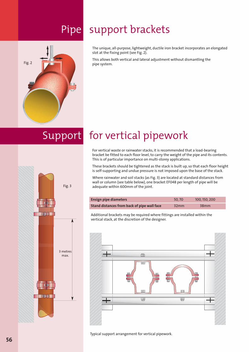
Pipe support brackets
56Typical support arrangement for vertical pipework.
Fig. 2
Ensign pipe diameters 50, 70 100, 150, 200Stand distances from back of pipe wall face 32mm 38mm
Additional brackets may be required where fittings are installed within thevertical stack, at the discretion of the designer.
Fig. 3
3 metresmax.
For vertical waste or rainwater stacks, it is recommended that a load-bearingbracket be fitted to each floor level, to carry the weight of the pipe and its contents.This is of particular importance on multi-storey applications.
These brackets should be tightened as the stack is built up, so that each floor heightis self-supporting and undue pressure is not imposed upon the base of the stack.
Where rainwater and soil stacks (as Fig. 3) are located at standard distances fromwall or column (see table below), one bracket EF048 per length of pipe will beadequate within 600mm of the joint.
Support for vertical pipework
The unique, all-purpose, lightweight, ductile iron bracket incorporates an elongatedslot at the fixing point (see Fig. 2).
This allows both vertical and lateral adjustment without dismantling thepipe system.
SGPL 116359 Ensign Manual Sect 3 and 4 2009 V6 MH:Layout 1 17/7/09 12:39 Page 56
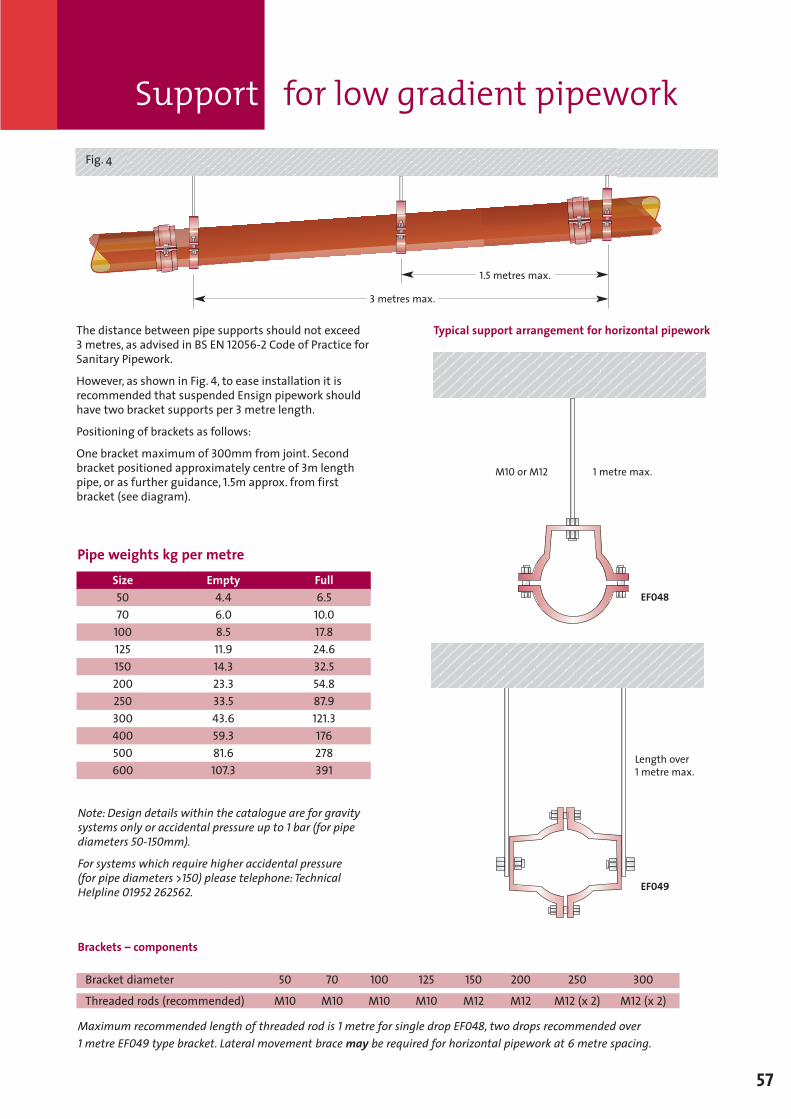
Support for low gradient pipework
57
The distance between pipe supports should not exceed3metres, as advised in BS EN 12056-2 Code of Practice forSanitary Pipework.
However, as shown in Fig. 4, to ease installation it isrecommended that suspended Ensign pipework shouldhave two bracket supports per 3metre length.
Positioning of brackets as follows:
One bracket maximum of 300mm from joint. Secondbracket positioned approximately centre of 3m lengthpipe, or as further guidance, 1.5m approx. from firstbracket (see diagram).
Typical support arrangement for horizontal pipework
Fig. 4
Note: Design details within the catalogue are for gravitysystems only or accidental pressure up to 1 bar (for pipediameters 50-150mm).
For systems which require higher accidental pressure(for pipe diameters >150) please telephone: TechnicalHelpline 01952 262562.
Size5070
100125150200250300400500600
Empty4.46.08.511.914.323.333.543.659.381.6107.3
Full6.5
10.017.824.632.554.887.9121.3176278391
Pipe weights kg per metre
Brackets – components
Bracket diameter 50 70 100 125 150 200 250 300
Threaded rods (recommended) M10 M10 M10 M10 M12 M12 M12 (x 2) M12 (x 2)
Maximum recommended length of threaded rod is 1 metre for single drop EF048, two drops recommended over1 metre EF049 type bracket. Lateral movement brace may be required for horizontal pipework at 6 metre spacing.
1 metre max.M10 or M12
EF048
Length over1 metre max.
EF049
3 metres max.
1.5 metres max.
SGPL 116359 Ensign Manual Sect 3 and 4 2009 V6 MH:Layout 1 17/7/09 12:39 Page 57
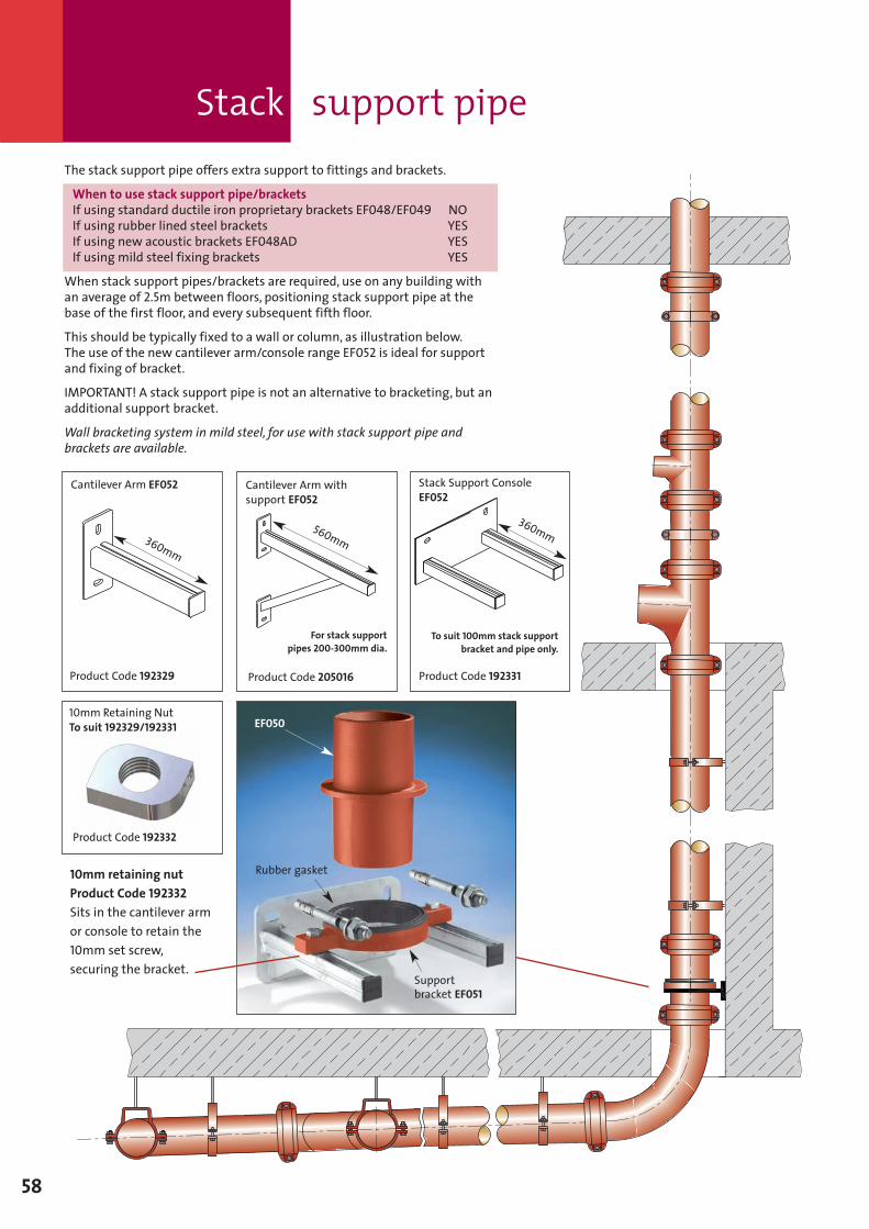
Stack support pipe
58
EF050
Rubber gasket
Supportbracket EF051
Cantilever Arm withsupport EF052
Cantilever Arm EF052
360mm
Stack Support ConsoleEF052
Product Code 205016Product Code 192329 Product Code 192331
360mm560mm
For stack supportpipes 200-300mm dia.
To suit 100mm stack supportbracket and pipe only.
10mm retaining nutProduct Code 192332Sits in the cantilever armor console to retain the10mm set screw,securing the bracket.
10mm Retaining NutTo suit 192329/192331
Product Code 192332
The stack support pipe offers extra support to fittings and brackets.
When to use stack support pipe/bracketsIf using standard ductile iron proprietary brackets EF048/EF049 NOIf using rubber lined steel brackets YESIf using new acoustic brackets EF048AD YESIf using mild steel fixing brackets YES
When stack support pipes/brackets are required, use on any building withan average of 2.5m between floors, positioning stack support pipe at thebase of the first floor, and every subsequent fifth floor.
This should be typically fixed to a wall or column, as illustration below.The use of the new cantilever arm/console range EF052 is ideal for supportand fixing of bracket.
IMPORTANT! A stack support pipe is not an alternative to bracketing, but anadditional support bracket.
Wall bracketing system in mild steel, for use with stack support pipe andbrackets are available.
SGPL 116359 Ensign Manual Sect 3 and 4 2009 V6 MH:Layout 1 17/7/09 12:39 Page 58
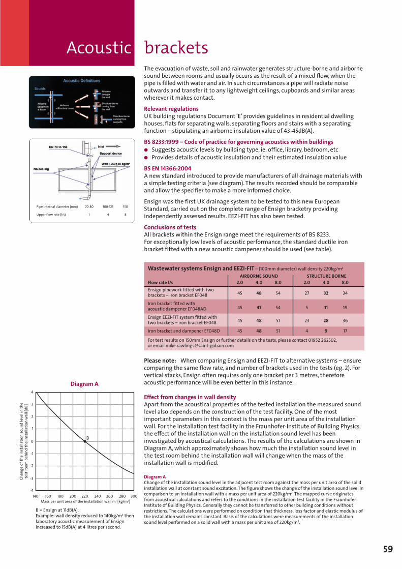
Acoustic brackets
59
The evacuation of waste, soil and rainwater generates structure-borne and airbornesound between rooms and usually occurs as the result of a mixed flow,when thepipe is filled with water and air. In such circumstances a pipe will radiate noiseoutwards and transfer it to any lightweight ceilings, cupboards and similar areaswherever it makes contact.
Relevant regulationsUK building regulations Document ‘E’ provides guidelines in residential dwellinghouses, flats for separating walls, separating floors and stairs with a separatingfunction – stipulating an airborne insulation value of 43-45dB(A).
BS 8233:1999 – Code of practice for governing acoustics within buildings� Suggests acoustic levels by building type, ie. office, library, bedroom, etc� Provides details of acoustic insulation and their estimated insulation value
BS EN 14366:2004A new standard introduced to provide manufacturers of all drainage materials witha simple testing criteria (see diagram). The results recorded should be comparableand allow the specifier to make a more informed choice.
Ensign was the first UK drainage system to be tested to this new EuropeanStandard, carried out on the complete range of Ensign bracketry providingindependently assessed results. EEZI-FIT has also been tested.
Conclusions of testsAll brackets within the Ensign range meet the requirements of BS 8233.For exceptionally low levels of acoustic performance, the standard ductile ironbracket fitted with a new acoustic dampener should be used (see table).
Please note: When comparing Ensign and EEZI-FIT to alternative systems – ensurecomparing the same flow rate, and number of brackets used in the tests (eg. 2). Forvertical stacks, Ensign often requires only one bracket per 3metres, thereforeacoustic performance will be even better in this instance.
Effect from changes in wall densityApart from the acoustical properties of the tested installation the measured soundlevel also depends on the construction of the test facility. One of the mostimportant parameters in this context is the mass per unit area of the installationwall. For the installation test facility in the Fraunhofer-Institute of Building Physics,the effect of the installation wall on the installation sound level has beeninvestigated by acoustical calculations. The results of the calculations are shown inDiagram A,which approximately shows howmuch the installation sound level inthe test room behind the installation wall will change when the mass of theinstallation wall is modified.
Diagram AChange of the installation sound level in the adjacent test room against the mass per unit area of the solidinstallation wall at constant sound excitation. The figure shows the change of the installation sound level incomparison to an installation wall with a mass per unit area of 220kg/m2. The mapped curve originatesfrom acoustical calculations and refers to the conditions in the installation test facility in the Fraunhofer-Institute of Building Physics. Generally they cannot be transferred to other building conditions withoutrestrictions. The calculations were performed on condition that thickness, loss factor and elastic modulus ofthe installation wall remains constant. Basis of the calculations were measurements of the installationsound level performed on a solid wall with a mass per unit area of 220kg/m2.
140-4
-3
-2
-1
0
1
2
3
4
160 180 200 220 240 260 280 300
Changeoftheinstallationsoundlevelinthe
testroom
behindtheinstallationwall[dB]
Mass per unit area of the installation wall m1 [kg/m2]
B = Ensign at 11dB(A).Example: wall density reduced to 140kg/m2 thenlaboratory acoustic measurement of Ensignincreased to 15dB(A) at 4 litres per second.
Diagram A
B
Pipe internal diameter (mm) 70-80 100-125 150
Upper flow rate (l/s) 1 4 8
Wastewater systems Ensign and EEZI-FIT – (100mm diameter) wall density 220kg/m2
AIRBORNE SOUND STRUCTURE BORNEFlow rate l/s 2.0 4.0 8.0 2.0 4.0 8.0Ensign pipework fitted with twobrackets – iron bracket EF048 45 48 54 27 32 34
Iron bracket fitted withacoustic dampener EF048AD 45 47 54 5 11 19
Ensign EEZI-FIT system fitted withtwo brackets – iron bracket EF048 45 48 51 23 28 36
Iron bracket and dampener EF048D 45 48 51 4 9 17
For test results on 150mm Ensign or further details on the tests, please contact 01952 262502,or email [email protected]
SGPL 116359 Ensign Manual Sect 3 and 4 2009 V6 MH:Layout 1 17/7/09 12:39 Page 59
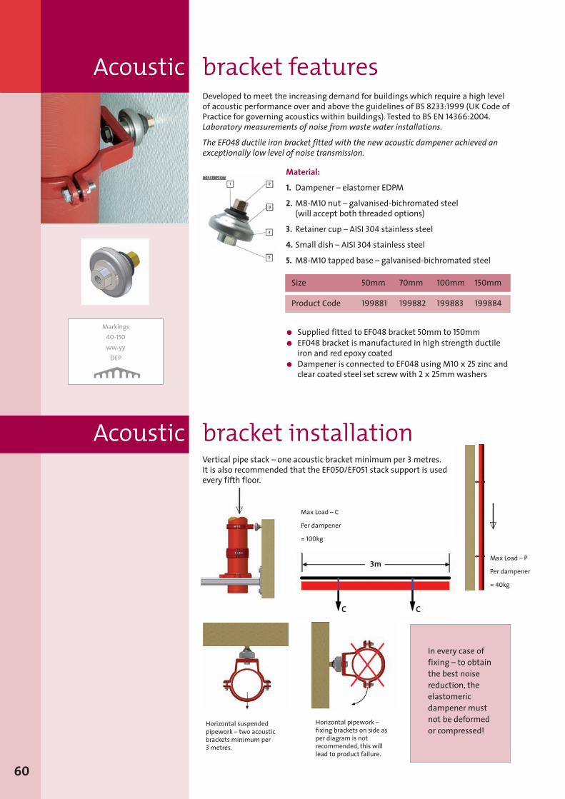
Developed to meet the increasing demand for buildings which require a high levelof acoustic performance over and above the guidelines of BS 8233:1999 (UK Code ofPractice for governing acoustics within buildings). Tested to BS EN 14366:2004.Laboratory measurements of noise from waste water installations.
The EF048 ductile iron bracket fitted with the new acoustic dampener achieved anexceptionally low level of noise transmission.
Material:
1. Dampener – elastomer EDPM
2. M8-M10 nut – galvanised-bichromated steel(will accept both threaded options)
3. Retainer cup – AISI 304 stainless steel
4. Small dish – AISI 304 stainless steel
5. M8-M10 tapped base – galvanised-bichromated steel
Size 50mm 70mm 100mm 150mm
Product Code 199881 199882 199883 199884
60
Acoustic bracket features
Markings40-150ww-yyDEP
� Supplied fitted to EF048 bracket 50mm to 150mm� EF048 bracket is manufactured in high strength ductileiron and red epoxy coated
� Dampener is connected to EF048 using M10 x 25 zinc andclear coated steel set screw with 2 x 25mmwashers
Acoustic bracket installationVertical pipe stack – one acoustic bracket minimum per 3metres.It is also recommended that the EF050/EF051 stack support is usedevery fifth floor.
Horizontal suspendedpipework – two acousticbrackets minimum per3metres.
Horizontal pipework –fixing brackets on side asper diagram is notrecommended, this willlead to product failure.
Max Load – P
Per dampener
= 40kg
Max Load – C
Per dampener
= 100kg
In every case offixing – to obtainthe best noisereduction, theelastomericdampener mustnot be deformedor compressed!
SGPL 116359 Ensign Manual Sect 3 and 4 2009 V6 MH:Layout 1 17/7/09 12:39 Page 60
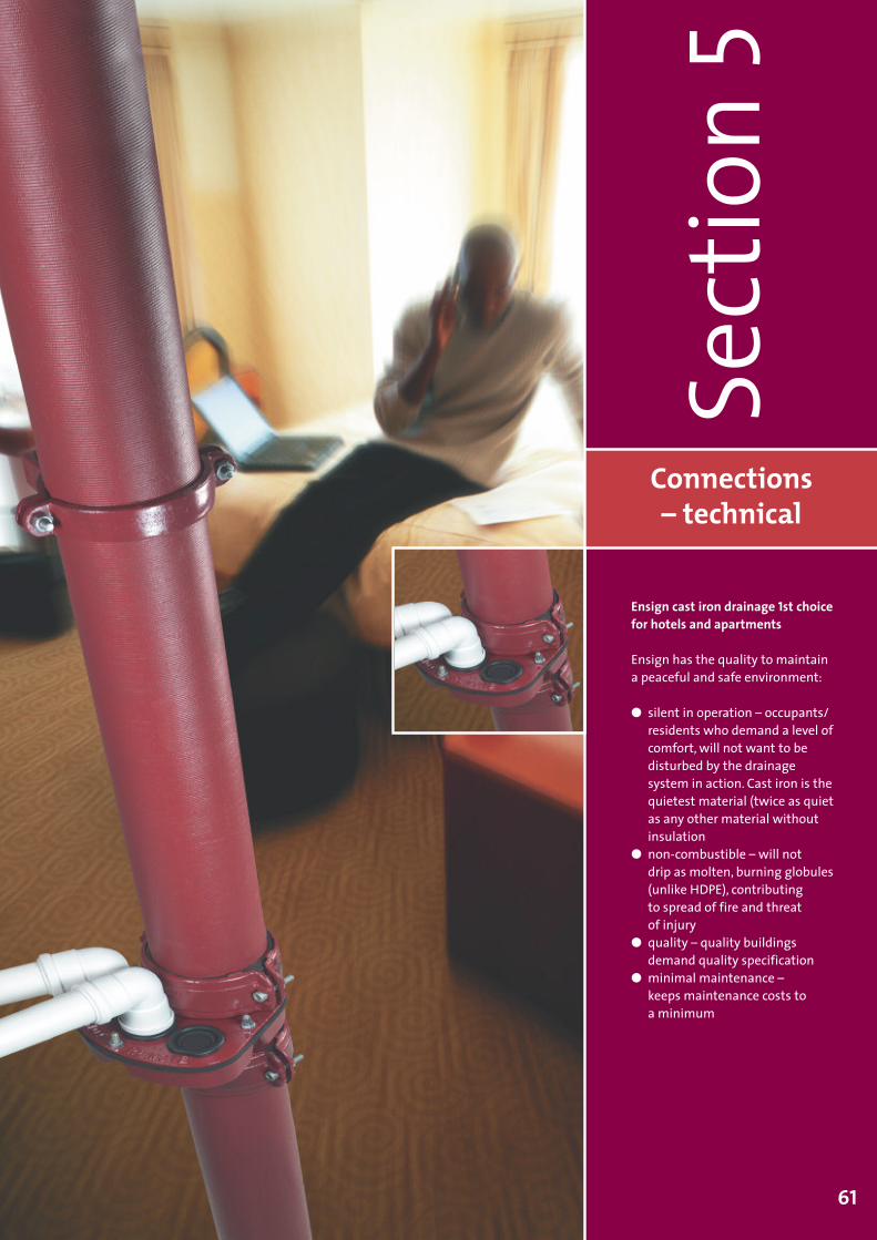
Connections– technical
Sect
ion5
61
Ensign cast iron drainage 1st choicefor hotels and apartments
Ensign has the quality to maintaina peaceful and safe environment:
� silent in operation – occupants/residents who demand a level ofcomfort, will not want to bedisturbed by the drainagesystem in action. Cast iron is thequietest material (twice as quietas any other material withoutinsulation
� non-combustible – will notdrip as molten, burning globules(unlike HDPE), contributingto spread of fire and threatof injury
� quality – quality buildingsdemand quality specification
� minimal maintenance –keeps maintenance costs toa minimum
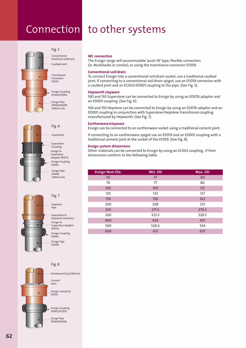
WC connectionThe Ensign range will accommodate ‘push-fit’ type, flexible connectors(ie.Multikwiks or similar), or using the transitional connector EF059.
Conventional soil/drainTo connect Ensign into a conventional soil/drain socket, use a traditional caulkedjoint. If connecting to a conventional soil/drain spigot, use an EF059 connector witha caulked joint and an EC002/ED001 coupling to the pipe. (See Fig. 5).
Hepworth clayware100 and 150 Supersleve can be connected to Ensign by using an ED076 adaptor andan ED001 coupling. (See Fig. 6).
100 and 150 Hepsleve can be connected to Ensign by using an ED076 adaptor and anED001 coupling in conjunction with Supersleve/Hepsleve transitional couplingmanufactured by Hepworth. (See Fig. 7).
Earthenware/claywareEnsign can be connected to an earthenware socket using a traditional cement joint.
If connecting to an earthenware spigot use an EF059 and an ED001 coupling with atraditional cement joint at the socket of the EF059. (See Fig. 8).
Ensign system dimensionsOther materials can be connected to Ensign by using an EC002 coupling , if theirdimensions conform to the following table:
62
Caulked Joint
TransitionalConnectorEF059
Ensign CouplingEC002/ED001
Ensign PipeEP000/ED000100mm dia.
ä
ä
ä
ConventionalSoil/Drain (100mm)
ä
ä
Supersleve
SupersleveCoupling
Ensign toSupersleveAdaptor ED076
Ensign PipeED000100mm dia.
ä
Ensign CouplingED001
ä
ä
ä
ä
HepslevePipe
ä
Supersleve toHepsleve Connector
ä
Ensign toSupersleve AdaptorED076
ä
Ensign PipeED000
ä
Ensign CouplingED001
ä
Densleeve/Clay (100mm)
Ensign CouplingED001/EC002
Ensign PipeED000/EP000
ä
ä
ä
Ensign ConnectorEF059
ä
CementJoint
ä
Fig. 5
Fig. 6
Fig. 7
Fig. 8
Ensign Nom Dia.5070
100125150200250300400500600
Min. OD5777
109133158208271.5323.5426
528.6631
Max. OD6080112137162212
276.5328.5431534637
Connection to other systems
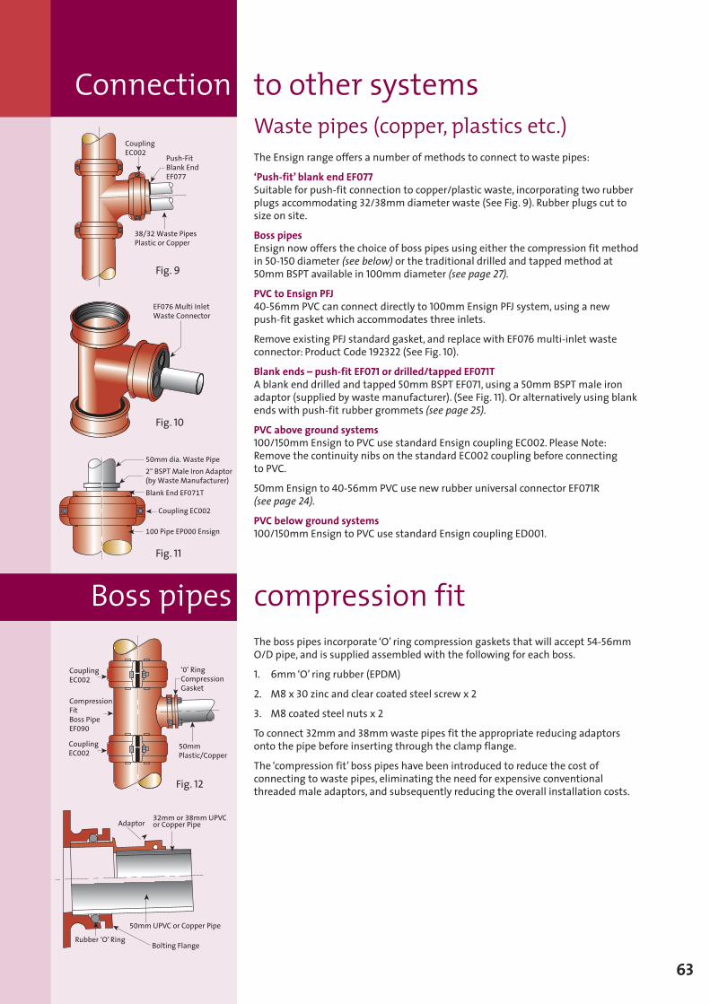
63
Waste pipes (copper, plastics etc.)The Ensign range offers a number of methods to connect to waste pipes:
‘Push-fit’ blank end EF077Suitable for push-fit connection to copper/plastic waste, incorporating two rubberplugs accommodating 32/38mm diameter waste (See Fig. 9). Rubber plugs cut tosize on site.
Boss pipesEnsign now offers the choice of boss pipes using either the compression fit methodin 50-150 diameter (see below) or the traditional drilled and tapped method at50mmBSPT available in 100mm diameter (see page 27).
PVC to Ensign PFJ40-56mm PVC can connect directly to 100mm Ensign PFJ system, using a newpush-fit gasket which accommodates three inlets.
Remove existing PFJ standard gasket, and replace with EF076 multi-inlet wasteconnector: Product Code 192322 (See Fig. 10).
Blank ends – push-fit EF071 or drilled/tapped EF071TA blank end drilled and tapped 50mmBSPT EF071, using a 50mmBSPT male ironadaptor (supplied by waste manufacturer). (See Fig. 11). Or alternatively using blankends with push-fit rubber grommets (see page 25).
PVC above ground systems100/150mm Ensign to PVC use standard Ensign coupling EC002. Please Note:Remove the continuity nibs on the standard EC002 coupling before connectingto PVC.
50mm Ensign to 40-56mm PVC use new rubber universal connector EF071R(see page 24).
PVC below ground systems100/150mm Ensign to PVC use standard Ensign coupling ED001.
The boss pipes incorporate ‘O’ ring compression gaskets that will accept 54-56mmO/D pipe, and is supplied assembled with the following for each boss.
1. 6mm‘O’ ring rubber (EPDM)
2. M8 x 30 zinc and clear coated steel screw x 2
3. M8 coated steel nuts x 2
To connect 32mm and 38mmwaste pipes fit the appropriate reducing adaptorsonto the pipe before inserting through the clamp flange.
The ‘compression fit’ boss pipes have been introduced to reduce the cost ofconnecting to waste pipes, eliminating the need for expensive conventionalthreaded male adaptors, and subsequently reducing the overall installation costs.
CouplingEC002
ä
38/32 Waste PipesPlastic or Copper
äPush-FitBlank EndEF077ä
Fig. 9
EF076 Multi Inlet Waste Connector
ä
Fig. 10
50mm dia. Waste Pipe
2" BSPT Male Iron Adaptor(by Waste Manufacturer)
Blank End EF071T
Coupling EC002
100 Pipe EP000 Ensign
ä
ä
ä
ä
ä
CouplingEC002
CompressionFitBoss PipeEF090
CouplingEC002
‘0’ RingCompressionGasketä
ä
ä
ä
ä
50mmPlastic/Copper
ä
32mm or 38mm UPVCor Copper Pipe
50mm UPVC or Copper Pipe
Rubber ‘O’ RingBolting Flange
ää
ä
ä
Adaptor
ä
Fig. 11
Fig. 12
Boss pipes compression fit
Connection to other systems
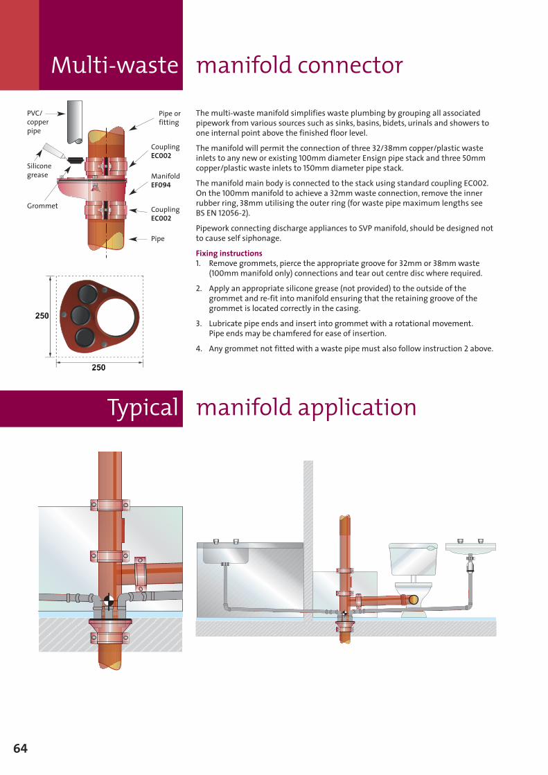
The multi-waste manifold simplifies waste plumbing by grouping all associatedpipework from various sources such as sinks, basins, bidets, urinals and showers toone internal point above the finished floor level.
The manifold will permit the connection of three 32/38mm copper/plastic wasteinlets to any new or existing 100mm diameter Ensign pipe stack and three 50mmcopper/plastic waste inlets to 150mm diameter pipe stack.
The manifold main body is connected to the stack using standard coupling EC002.On the 100mmmanifold to achieve a 32mmwaste connection, remove the innerrubber ring, 38mmutilising the outer ring (for waste pipe maximum lengths seeBS EN 12056-2).
Pipework connecting discharge appliances to SVP manifold, should be designed notto cause self siphonage.
Fixing instructions1. Remove grommets, pierce the appropriate groove for 32mm or 38mmwaste
(100mmmanifold only) connections and tear out centre disc where required.
2. Apply an appropriate silicone grease (not provided) to the outside of thegrommet and re-fit into manifold ensuring that the retaining groove of thegrommet is located correctly in the casing.
3. Lubricate pipe ends and insert into grommet with a rotational movement.Pipe ends may be chamfered for ease of insertion.
4. Any grommet not fitted with a waste pipe must also follow instruction 2 above.
Pipe orfitting
CouplingEC002
CouplingEC002
Pipe
PVC/copperpipe
Siliconegrease
Grommet
ManifoldEF094
Typical manifold application
64
Multi-waste manifold connector
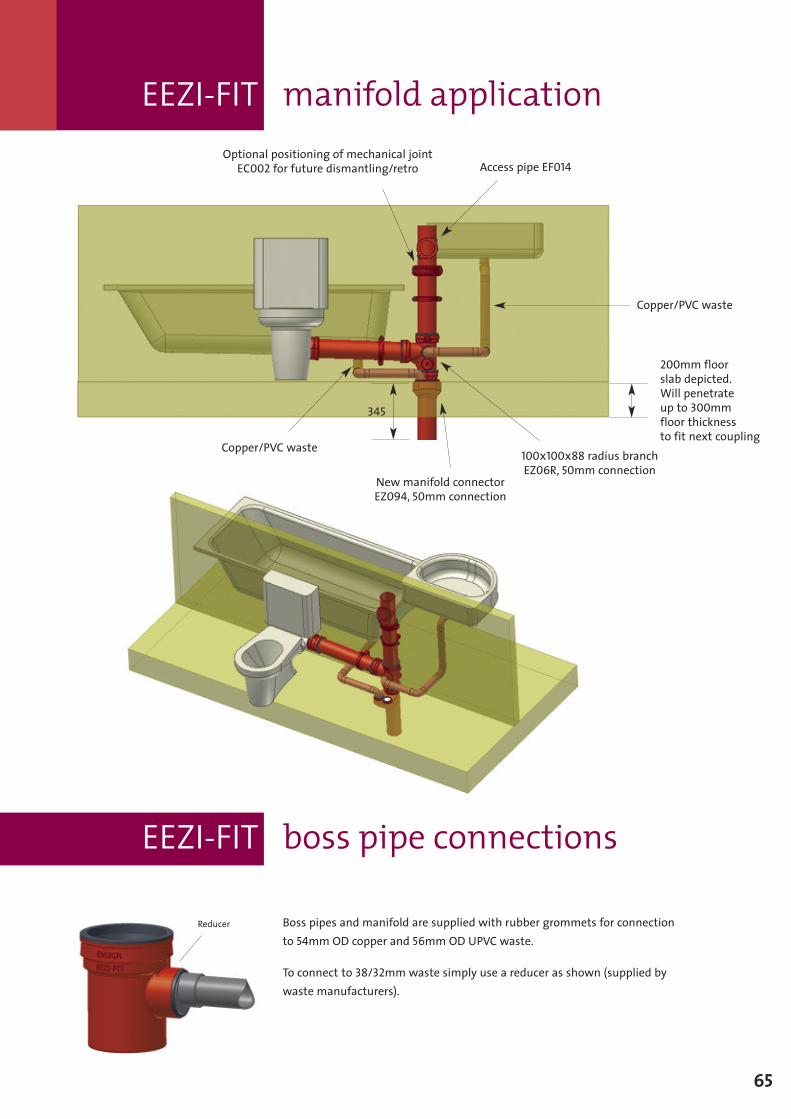
EEZI-FIT boss pipe connections
65
Access pipe EF014
Copper/PVC waste
New manifold connectorEZ094, 50mm connection
Copper/PVC waste
345
100x100x88 radius branchEZ06R, 50mm connection
200mm floorslab depicted.Will penetrateup to 300mmfloor thicknessto fit next coupling
Optional positioning of mechanical jointEC002 for future dismantling/retro
Boss pipes and manifold are supplied with rubber grommets for connectionto 54mm OD copper and 56mm OD UPVC waste.
To connect to 38/32mmwaste simply use a reducer as shown (supplied bywaste manufacturers).
Reducer
EEZI-FIT manifold application
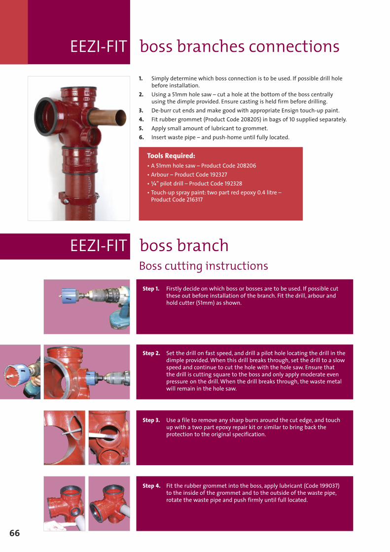
66
1. Simply determine which boss connection is to be used. If possible drill holebefore installation.
2. Using a 51mm hole saw – cut a hole at the bottom of the boss centrallyusing the dimple provided. Ensure casting is held firm before drilling.
3. De-burr cut ends and make good with appropriate Ensign touch-up paint.4. Fit rubber grommet (Product Code 208205) in bags of 10 supplied separately.5. Apply small amount of lubricant to grommet.6. Insert waste pipe – and push-home until fully located.
Boss cutting instructions
Tools Required:• A 51mm hole saw – Product Code 208206• Arbour – Product Code 192327•W" pilot drill – Product Code 192328• Touch-up spray paint: two part red epoxy 0.4 litre –Product Code 216317
EEZI-FIT boss branch
Step 1. Firstly decide on which boss or bosses are to be used. If possible cutthese out before installation of the branch. Fit the drill, arbour andhold cutter (51mm) as shown.
Step 2. Set the drill on fast speed, and drill a pilot hole locating the drill in thedimple provided.When this drill breaks through, set the drill to a slowspeed and continue to cut the hole with the hole saw. Ensure thatthe drill is cutting square to the boss and only apply moderate evenpressure on the drill.When the drill breaks through, the waste metalwill remain in the hole saw.
Step 3. Use a file to remove any sharp burrs around the cut edge, and touchup with a two part epoxy repair kit or similar to bring back theprotection to the original specification.
Step 4. Fit the rubber grommet into the boss, apply lubricant (Code 199037)to the inside of the grommet and to the outside of the waste pipe,rotate the waste pipe and push firmly until full located.
EEZI-FIT boss branches connections

67
Cricket pipe carrier
To assist on site with transporting larger diameter pipes and fittings there is theCricket pipe carrier:
� Transport 20ft (6.1m) pipe lengths up to 1,000lb (450kg)� Comes with ratchet hold-down strap and 16" tubed tyres� Weighs only 80lb (36.0kg)� Quick handle disconnect for compact storage
Easy use:
Step 1.Use ratchet hold-down strap to secure Cricket to pipe.
Step 2.Use handle to flip Cricket and pipe.
Step 3. Reposition handle. Great for carrying flanges, fittings and valves.
Scorp 220 cutter
� The ultimate and fast solution for cutting of cast iron 50mmup to 200mm� Easy, secure and effortless cutting during use on construction sites� Wide range of applications and dimensions� No rework necessary� Suitable for clamping joints� Reduction of tool costs
Hand-held cordless impact driver
Saint-Gobain PAM UK has conducted a number of field trials on handheld cordlessdrills,with experienced installers of cast iron drainage systems.The purpose was toidentify tools which reduce the time taken to install cast ironmechanical couplings,but are also practical and easy to use in site conditions where space can be limited.
Field trials – research findings
� Using a cordless drill reduced the time taken to assemble a ductile iron couplingby up to 50%
� Plumbing installers found saving in time significantly increased on largerdiameter couplings which incorporate four fixing bolts (150-300mm)
� Experienced plumbing installers who trialled the hand-held drills reportedsignificant savings in time, and improved productivity on site
A number of cordless drills were trialled onmany sites. The best all roundperformer being:
Cordless impact wrench Bosch GD14.4v (shown)
� High torque and high impact force ensure optimum performance� New battery technology extends the service life of the batteries by 50%� ½ hour charger (standard equipment) enables fastest recharging� High level of comfort� Compact and ergonomic shape� Very good power/weight ratio ensures fatigue-free working� Gear housingmade of metal for maximum precision and long service life� Safe working without recoil� Three-fold adjustable light ensures optimum visibility, even in dark areas
NOTE:These devices are not manufactured or supplied by Saint-Gobain PAM UKbut are available via reputable dealers.
Typical labour saving devices
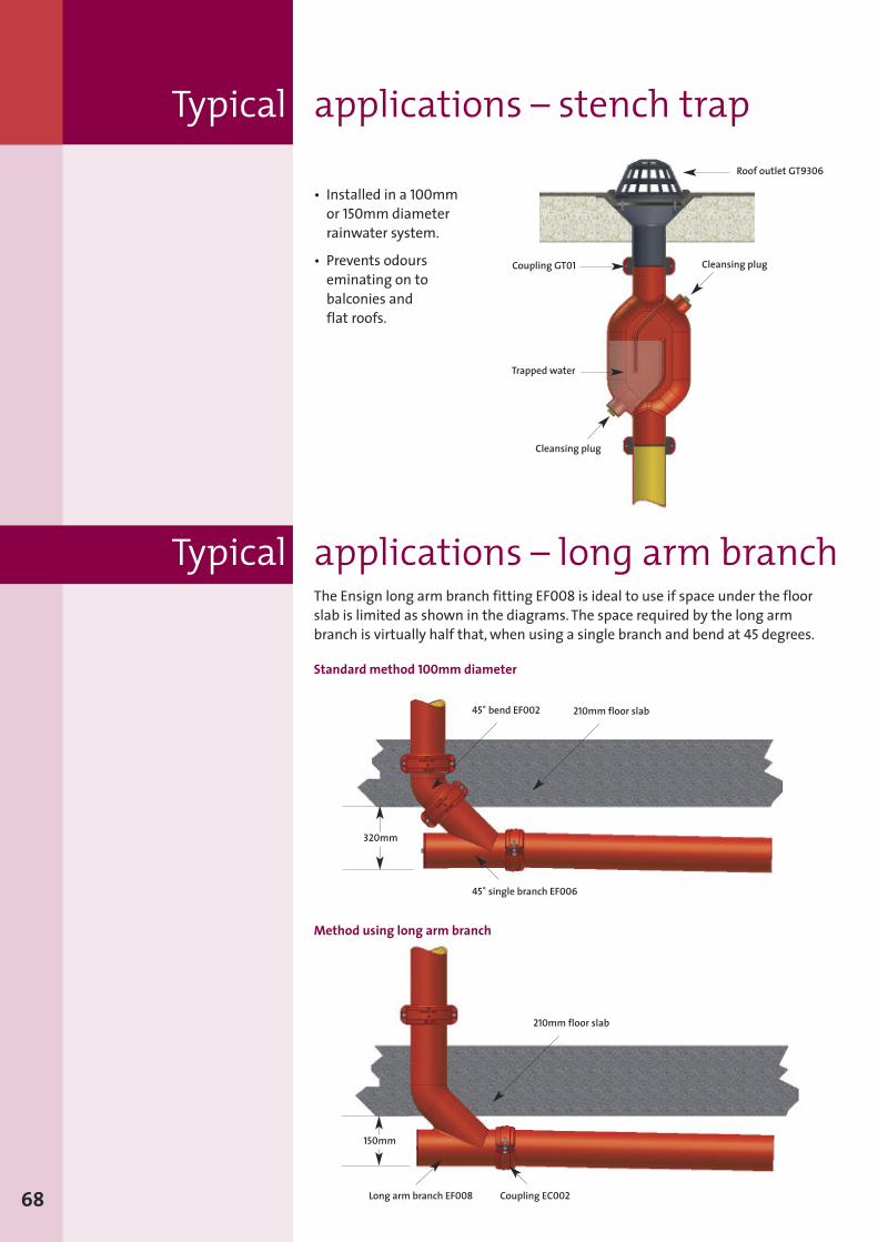
45˚ bend EF002
45˚ single branch EF006
320mm
210mm floor slab
Coupling EC002
150mm
Long arm branch EF008
• Installed in a 100mmor 150mmdiameterrainwater system.
• Prevents odourseminating on tobalconies andflat roofs.
68
Typical applications – long arm branchThe Ensign long arm branch fitting EF008 is ideal to use if space under the floorslab is limited as shown in the diagrams.The space required by the long armbranch is virtually half that,when using a single branch and bend at 45 degrees.
Standard method 100mm diameter
Method using long arm branch
Coupling GT01
Roof outlet GT9306
Trapped water
Cleansing plug
Cleansing plug
Typical applications – stench trap
210mm floor slab
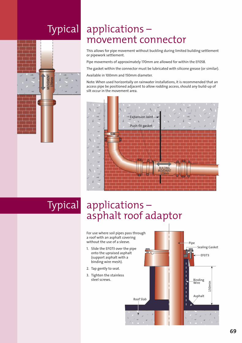
69
MOV
EMEN
T170m
m
Expansion Joint
BUILDINGMOVEMENT170mm
Push-fit gasket
150m
in
ä
ä
BindingWire
Asphalt
ä
ä
EF073
Sealing Gasket
ä
Pipeä
ä
Roof Slab
ä
For use where soil pipes pass througha roof with an asphalt coveringwithout the use of a sleeve.
1. Slide the EF073 over the pipeonto the upraised asphalt(support asphalt with abinding wire mesh).
2. Tap gently to seat.
3. Tighten the stainlesssteel screws.
Typical applications –asphalt roof adaptor
Typical applications –movement connectorThis allows for pipe movement without buckling during limited building settlementor pipework settlement.
Pipe movements of approximately 170mm are allowed for within the EF058.
The gasket within the connector must be lubricated with silicone grease (or similar).
Available in 100mm and 150mm diameter.
Note:When used horizontally on rainwater installations, it is recommended that anaccess pipe be positioned adjacent to allow rodding access, should any build-up ofsilt occur in the movement area.
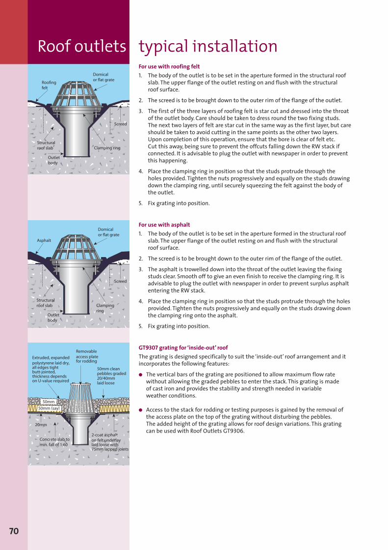
For use with roofing felt1. The body of the outlet is to be set in the aperture formed in the structural roof
slab. The upper flange of the outlet resting on and flush with the structuralroof surface.
2. The screed is to be brought down to the outer rim of the flange of the outlet.
3. The first of the three layers of roofing felt is star cut and dressed into the throatof the outlet body. Care should be taken to dress round the two fixing studs.The next two layers of felt are star cut in the same way as the first layer, but careshould be taken to avoid cutting in the same points as the other two layers.Upon completion of this operation, ensure that the bore is clear of felt etc.Cut this away, being sure to prevent the offcuts falling down the RW stack ifconnected. It is advisable to plug the outlet with newspaper in order to preventthis happening.
4. Place the clamping ring in position so that the studs protrude through theholes provided. Tighten the nuts progressively and equally on the studs drawingdown the clamping ring, until securely squeezing the felt against the body ofthe outlet.
5. Fix grating into position.
For use with asphalt1. The body of the outlet is to be set in the aperture formed in the structural roof
slab. The upper flange of the outlet resting on and flush with the structuralroof surface.
2. The screed is to be brought down to the outer rim of the flange of the outlet.
3. The asphalt is trowelled down into the throat of the outlet leaving the fixingstuds clear. Smooth off to give an even finish to receive the clamping ring. It isadvisable to plug the outlet with newspaper in order to prevent surplus asphaltentering the RW stack.
4. Place the clamping ring in position so that the studs protrude through the holesprovided. Tighten the nuts progressively and equally on the studs drawing downthe clamping ring onto the asphalt.
5. Fix grating into position.
GT9307 grating for ‘inside-out’ roofThe grating is designed specifically to suit the ‘inside-out’ roof arrangement and itincorporates the following features:
� The vertical bars of the grating are positioned to allowmaximum flow ratewithout allowing the graded pebbles to enter the stack. This grating is madeof cast iron and provides the stability and strength needed in variableweather conditions.
� Access to the stack for rodding or testing purposes is gained by the removal ofthe access plate on the top of the grating without disturbing the pebbles.The added height of the grating allows for roof design variations. This gratingcan be used with Roof Outlets GT9306.
70
Roof outlets typical installation
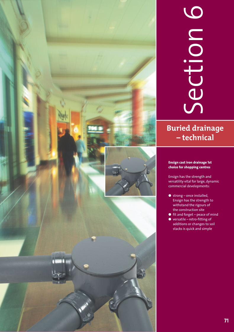
Buried drainage– technical
Sect
ion6
71
Ensign cast iron drainage 1stchoice for shopping centres
Ensign has the strength andversatility vital for large, dynamiccommercial developments:
� strong – once installed,Ensign has the strength towithstand the rigours ofthe construction site
� fit and forget – peace of mind� versatile – retro-fitting of
additions or changes to soilstacks is quick and simple
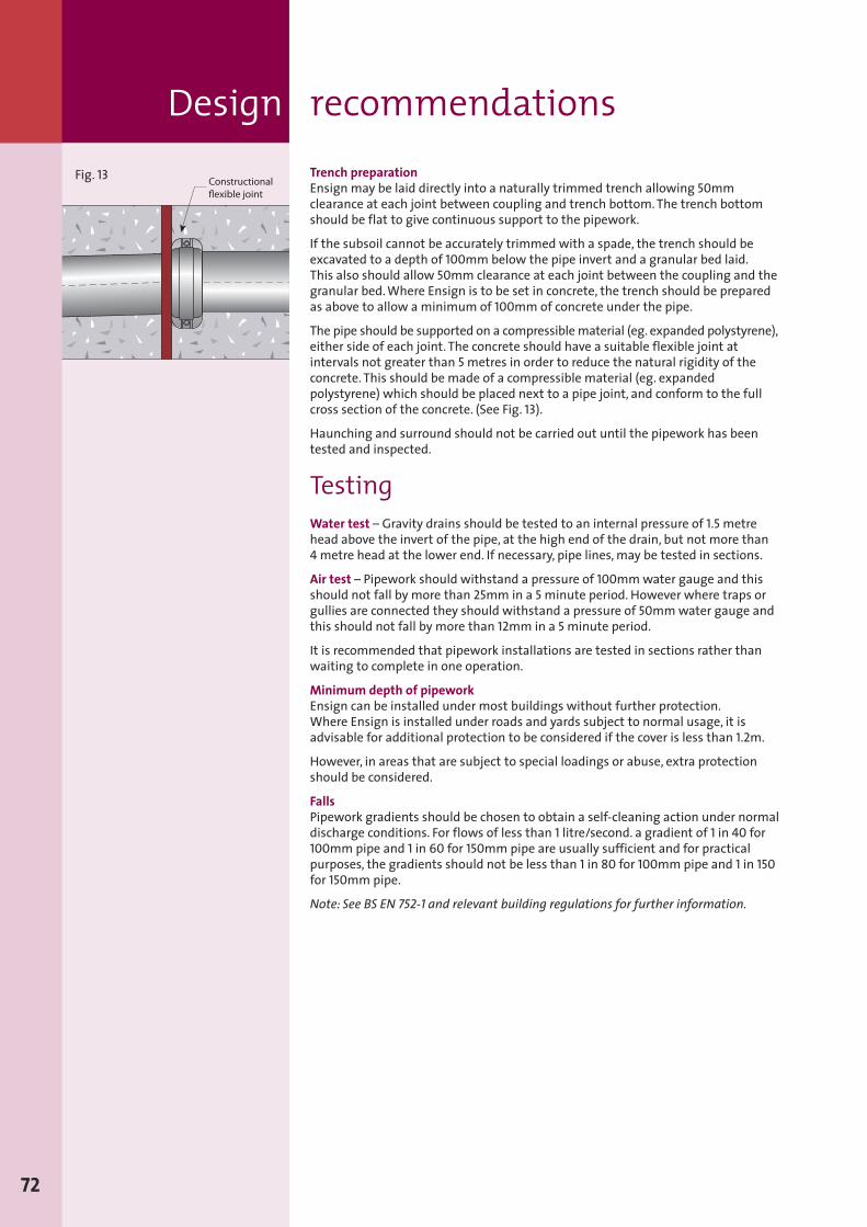
Trench preparationEnsign may be laid directly into a naturally trimmed trench allowing 50mmclearance at each joint between coupling and trench bottom.The trench bottomshould be flat to give continuous support to the pipework.
If the subsoil cannot be accurately trimmed with a spade, the trench should beexcavated to a depth of 100mm below the pipe invert and a granular bed laid.This also should allow 50mm clearance at each joint between the coupling and thegranular bed.Where Ensign is to be set in concrete, the trench should be preparedas above to allow a minimum of 100mm of concrete under the pipe.
The pipe should be supported on a compressiblematerial (eg. expanded polystyrene),either side of each joint. The concrete should have a suitable flexible joint atintervals not greater than 5 metres in order to reduce the natural rigidity of theconcrete. This should be made of a compressible material (eg. expandedpolystyrene) which should be placed next to a pipe joint, and conform to the fullcross section of the concrete. (See Fig. 13).
Haunching and surround should not be carried out until the pipework has beentested and inspected.
TestingWater test – Gravity drains should be tested to an internal pressure of 1.5 metrehead above the invert of the pipe, at the high end of the drain, but not more than4 metre head at the lower end. If necessary, pipe lines,may be tested in sections.
Air test – Pipework should withstand a pressure of 100mmwater gauge and thisshould not fall by more than 25mm in a 5 minute period. However where traps orgullies are connected they should withstand a pressure of 50mmwater gauge andthis should not fall by more than 12mm in a 5 minute period.
It is recommended that pipework installations are tested in sections rather thanwaiting to complete in one operation.
Minimum depth of pipeworkEnsign can be installed under most buildings without further protection.Where Ensign is installed under roads and yards subject to normal usage, it isadvisable for additional protection to be considered if the cover is less than 1.2m.
However, in areas that are subject to special loadings or abuse, extra protectionshould be considered.
FallsPipework gradients should be chosen to obtain a self-cleaning action under normaldischarge conditions. For flows of less than 1 litre/second. a gradient of 1 in 40 for100mm pipe and 1 in 60 for 150mm pipe are usually sufficient and for practicalpurposes, the gradients should not be less than 1 in 80 for 100mm pipe and 1 in 150for 150mm pipe.
Note: See BS EN 752-1 and relevant building regulations for further information.
ä
72
Fig. 13
Design recommendations
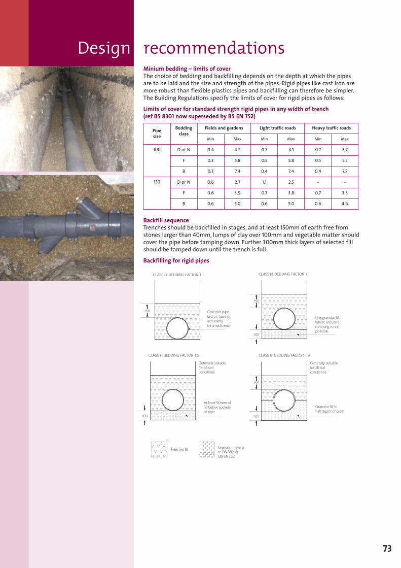
Minium bedding – limits of coverThe choice of bedding and backfilling depends on the depth at which the pipesare to be laid and the size and strength of the pipes. Rigid pipes like cast iron aremore robust than flexible plastics pipes and backfilling can therefore be simpler.The Building Regulations specify the limits of cover for rigid pipes as follows:
Limits of cover for standard strength rigid pipes in any width of trench(ref BS 8301 now superseded by BS EN 752)
Backfill sequenceTrenches should be backfilled in stages, and at least 150mm of earth free fromstones larger than 40mm, lumps of clay over 100mm and vegetable matter shouldcover the pipe before tamping down. Further 300mm thick layers of selected fillshould be tamped down until the trench is full.
Backfilling for rigid pipes
Pipesize
Beddingclass
Fields and gardens Light traffic roads Heavy traffic roads
Min Max Min Max Min Max
100 D or N 0.4 4.2 0.7 4.1 0.7 3.7
F 0.3 5.8 0.5 5.8 0.5 5.5
B 0.3 7.4 0.4 7.4 0.4 7.2
150 D or N 0.6 2.7 1.1 2.5 – –
F 0.6 3.9 0.7 3.8 0.7 3.3
B 0.6 5.0 0.6 5.0 0.6 4.6
73
Design recommendations
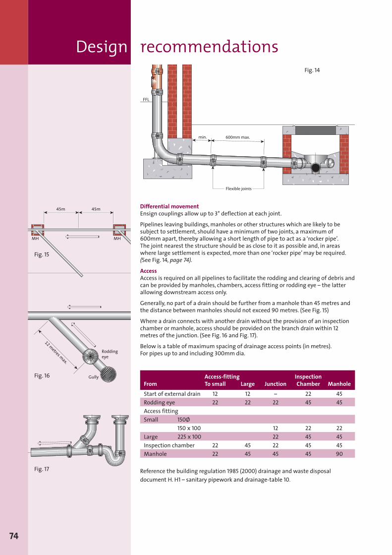
Design recommendations
Differential movementEnsign couplings allow up to 3° deflection at each joint.
Pipelines leaving buildings,manholes or other structures which are likely to besubject to settlement, should have a minimum of two joints, a maximum of600mm apart, thereby allowing a short length of pipe to act as a ‘rocker pipe’.The joint nearest the structure should be as close to it as possible and, in areaswhere large settlement is expected,more than one ‘rocker pipe’may be required.(See Fig. 14, page 74).
AccessAccess is required on all pipelines to facilitate the rodding and clearing of debris andcan be provided by manholes, chambers, access fitting or rodding eye – the latterallowing downstream access only.
Generally, no part of a drain should be further from amanhole than 45 metres andthe distance between manholes should not exceed 90 metres. (See Fig. 15)
Where a drain connects with another drain without the provision of an inspectionchamber or manhole, access should be provided on the branch drain within 12metres of the junction. (See Fig. 16 and Fig. 17).
Below is a table of maximum spacing of drainage access points (in metres).For pipes up to and including 300mmdia.
74
ä
ä
ä
ä45m 45m
MHMH
Roddingeye
ä
Gully
ä
12 metres m
ax.
Fig. 14
Fig. 16
Fig. 17
Fig. 15
Access-fitting InspectionFrom To small Large Junction Chamber ManholeStart of external drain 12 12 – 22 45Rodding eye 22 22 22 45 45Access fittingSmall 150Ø
150 x 100 12 22 22Large 225 x 100 22 45 45Inspection chamber 22 45 22 45 45Manhole 22 45 45 45 90
Reference the building regulation 1985 (2000) drainage and waste disposaldocument H. H1 – sanitary pipework and drainage-table 10.
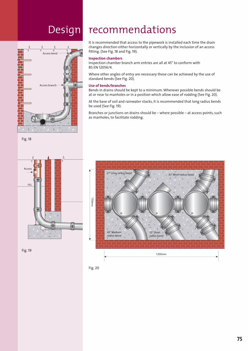
It is recommended that access to the pipework is installed each time the drainchanges direction either horizontally or vertically by the inclusion of an accessfitting. (See Fig. 18 and Fig. 19).
Inspection chambersInspection chamber branch arm entries are all at 45° to conform withBS EN 12056/4.
Where other angles of entry are necessary these can be achieved by the use ofstandard bends (See Fig. 20).
Use of bends/branchesBends in drains should be kept to a minimum.Wherever possible bends should beat or near to manholes or in a position which allow ease of rodding (See Fig. 20).
At the base of soil and rainwater stacks, it is recommended that long radius bendsbe used (See Fig. 19).
Branches or junctions on drains should be – where possible – at access points, suchas manholes, to facilitate rodding.
ä
Fig. 18
Fig. 19
Fig. 20
Design recommendations
75
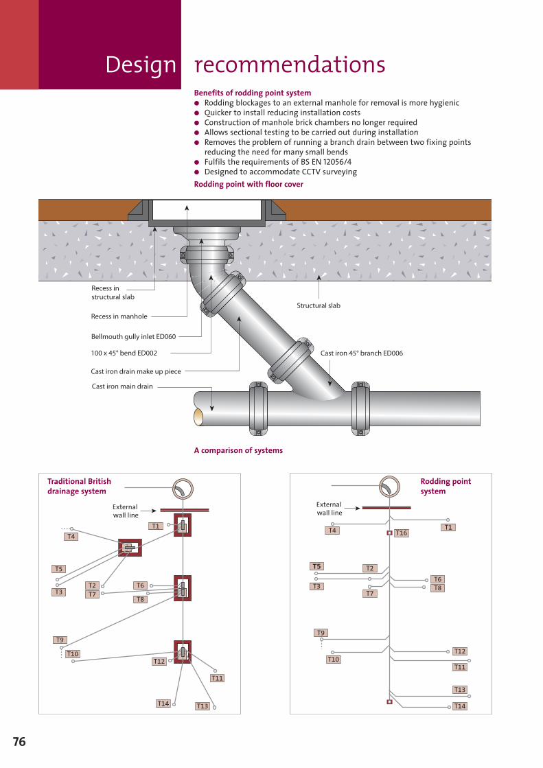
Design recommendationsBenefits of rodding point system� Rodding blockages to an external manhole for removal is more hygienic� Quicker to install reducing installation costs� Construction of manhole brick chambers no longer required� Allows sectional testing to be carried out during installation� Removes the problem of running a branch drain between two fixing points
reducing the need for many small bends� Fulfils the requirements of BS EN 12056/4� Designed to accommodate CCTV surveyingRodding point with floor cover
A comparison of systems
76
T1
T4
T5
T3T2T7
T6
T8
T9
T10T12
T14 T13
T11
Externalwall line
ä Externalwall line
T
T10
T9
T7
T2
T4 T16T1
T6T8
T12
T11
T13
T14
T3
T5
ä
Traditional Britishdrainage system
Rodding pointsystem
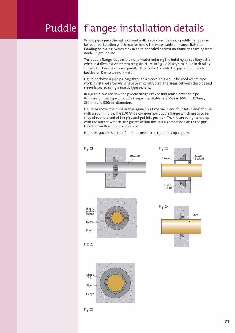
Where pipes pass through external walls, in basement areas, a puddle flange maybe required. Location which may be below the water table or in areas liable toflooding or in areas which may need to be sealed against methane gas coming frommade up ground etc.
The puddle flange reduces the risk of water entering the building by capillary actionwhen installed in a water retaining structure. In Figure 21 a typical build in detail isshown.The two-piece loose puddle flange is bolted onto the pipe once it has beenbedded on Denso tape or similar.
Figure 22 shows a pipe passing through a sleeve. This would be used where pipework is installed after walls have been constructed. The areas between the pipe andsleeve is sealed using a mastic type sealant.
In Figure 23 we see how the puddle flange is fixed and sealed onto the pipe.With Ensign this type of puddle flange is available as ED078 in 100mm, 150mm,250mm and 300mm diameters.
Figure 24 shows the build in type again, this time one piece (four set screws) for usewith a 200mm pipe. The ED078 is a compression puddle flange which needs to beslipped over the end of the pipe and put into position. Then it can be tightened upwith the ratchet wrench. The gasket within the unit is compressed on to the pipe,therefore no Denso tape is required.
Figure 25 you can see that four bolts need to be tightened up equally.
77
100/150
ä
Bolt onpuddleflange
Pipe
Denso ä
ä
ää
Flange
Pipe
Clampring
ä
ä
ä
200
ä
MasticSealant
ä
PuddleFlange
ä
Sleeve ä
Fig. 21 Fig. 22
Fig. 23
Fig. 24
Fig. 25
Puddle flanges installation details
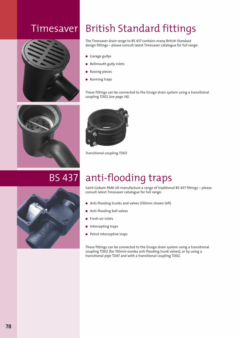
78
The Timesaver drain range to BS 437 contains many British Standarddesign fittings – please consult latest Timesaver catalogue for full range:
� Garage gullys
� Bellmouth gully inlets
� Raising pieces
� Running traps
These fittings can be connected to the Ensign drain system using a transitionalcoupling TD02 (see page 34).
Transitional coupling TD02
Saint-Gobain PAM UK manufacture a range of traditional BS 437 fittings – pleaseconsult latest Timesaver catalogue for full range:
� Anti-flooding trunks and valves (150mm shown left)
� Anti-flooding ball valves
� Fresh-air inlets
� Intercepting traps
� Petrol interceptive traps
These fittings can be connected to the Ensign drain system using a transitionalcoupling TD02 (for 150mm eureka anti-flooding trunk valves), or by using atransitional pipe TD47 and with a transitional coupling TD02.
BS 437 anti-flooding traps
Timesaver British Standard fittings
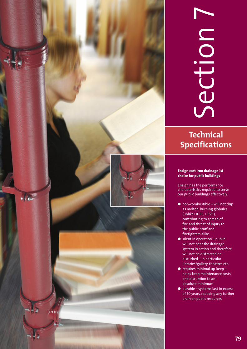
TechnicalSpecifications
Sect
ion7
79
Ensign cast iron drainage 1stchoice for public buildings
Ensign has the performancecharacteristics required to serveour public buildings effectively:
� non-combustible – will not dripas molten, burning globules(unlike HDPE, UPVC),contributing to spread offire and threat of injury tothe public, staff andfirefighters alike
� silent in operation – publicwill not hear the drainagesystem in action and thereforewill not be distracted ordisturbed – in particularlibraries/gallery-theatres etc.
� requires minimal up-keep –helps keep maintenance costsand disruption to anabsolute minimum
� durable – systems last in excessof 50 years, reducing any furtherdrain on public resources
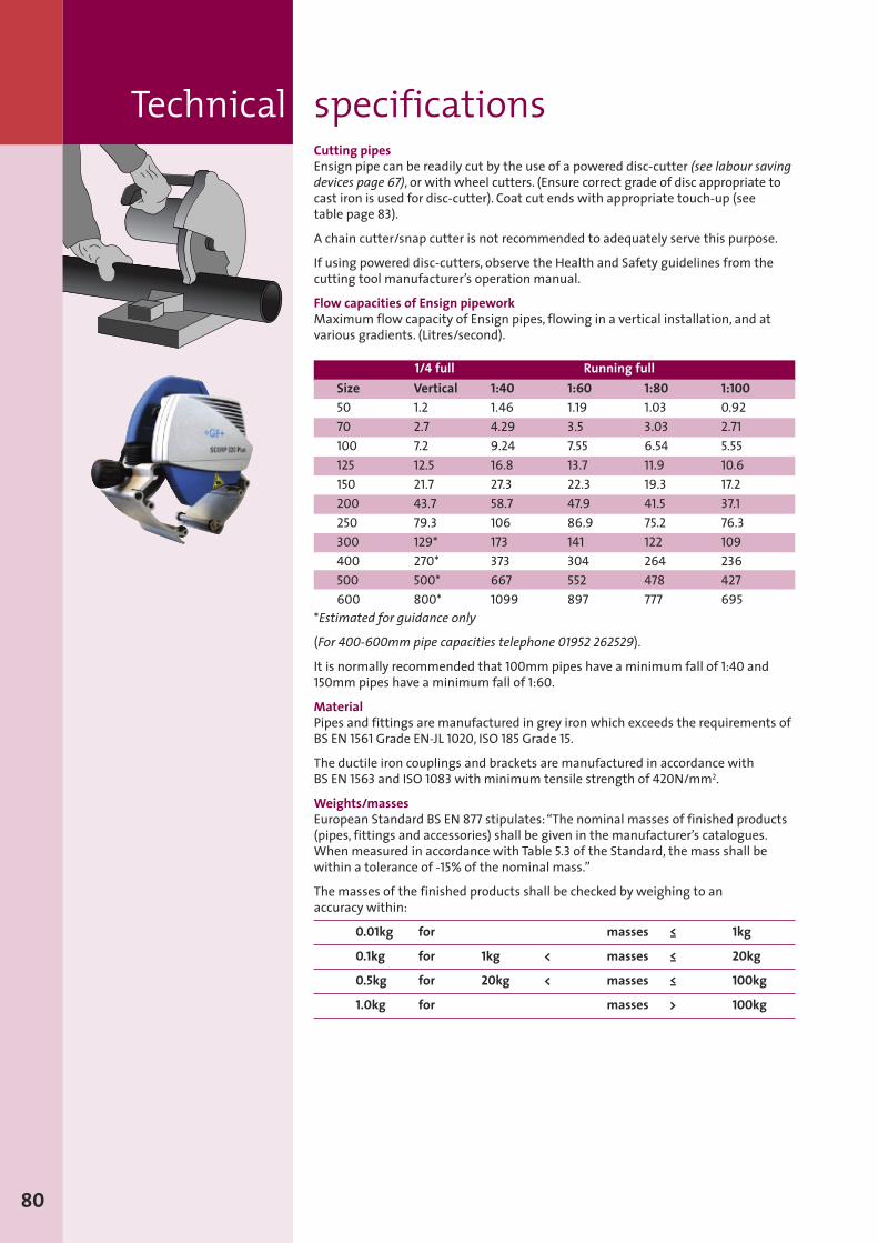
Technical specifications
80
Cutting pipesEnsign pipe can be readily cut by the use of a powered disc-cutter (see labour savingdevices page 67), or with wheel cutters. (Ensure correct grade of disc appropriate tocast iron is used for disc-cutter). Coat cut ends with appropriate touch-up (seetable page 83).
A chain cutter/snap cutter is not recommended to adequately serve this purpose.
If using powered disc-cutters, observe the Health and Safety guidelines from thecutting tool manufacturer’s operation manual.
Flow capacities of Ensign pipeworkMaximum flow capacity of Ensign pipes, flowing in a vertical installation, and atvarious gradients. (Litres/second).
*Estimated for guidance only
(For 400-600mm pipe capacities telephone 01952 262529).
It is normally recommended that 100mm pipes have a minimum fall of 1:40 and150mm pipes have a minimum fall of 1:60.
MaterialPipes and fittings are manufactured in grey iron which exceeds the requirements ofBS EN 1561 Grade EN-JL 1020, ISO 185 Grade 15.
The ductile iron couplings and brackets are manufactured in accordance withBS EN 1563 and ISO 1083with minimum tensile strength of 420N/mm2.
Weights/massesEuropean Standard BS EN 877 stipulates:“The nominal masses of finished products(pipes, fittings and accessories) shall be given in the manufacturer’s catalogues.Whenmeasured in accordance with Table 5.3 of the Standard, the mass shall bewithin a tolerance of -15% of the nominal mass.”
The masses of the finished products shall be checked by weighing to anaccuracy within:
0.01kg for masses ≤ 1kg
0.1kg for 1kg < masses ≤ 20kg
0.5kg for 20kg < masses ≤ 100kg
1.0kg for masses > 100kg
Running full1/4 fullSize5070100125150200250300400500600
Vertical1.22.77.212.521.743.779.3129*270*500*800*
1:401.464.299.2416.827.358.71061733736671099
1:601.193.57.5513.722.347.986.9141304552897
1:801.033.036.5411.919.341.575.2122264478777
1:1000.922.715.5510.617.237.176.3109236427695
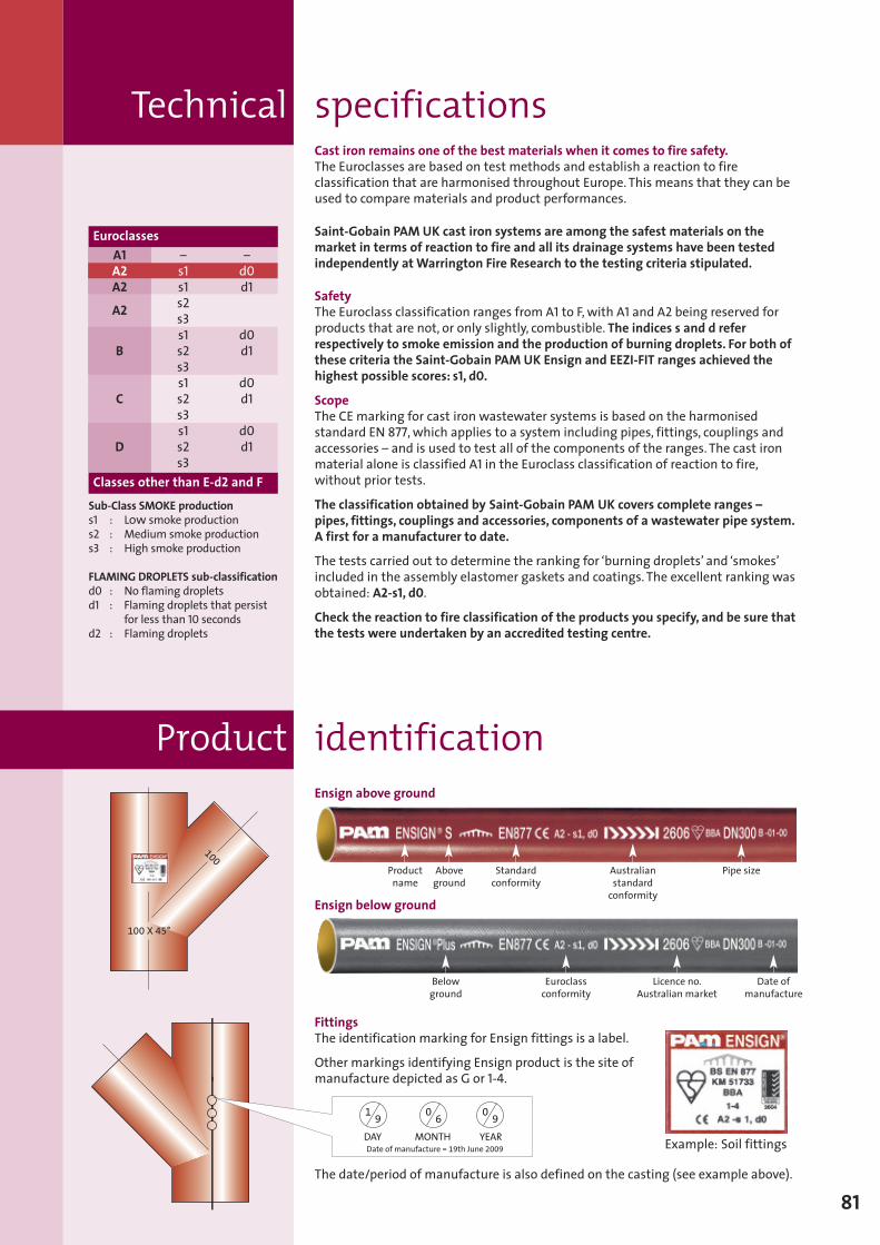
Cast iron remains one of the best materials when it comes to fire safety.The Euroclasses are based on test methods and establish a reaction to fireclassification that are harmonised throughout Europe. This means that they can beused to compare materials and product performances.
Saint-Gobain PAM UK cast iron systems are among the safest materials on themarket in terms of reaction to fire and all its drainage systems have been testedindependently atWarrington Fire Research to the testing criteria stipulated.
SafetyThe Euroclass classification ranges from A1 to F,with A1 and A2 being reserved forproducts that are not, or only slightly, combustible. The indices s and d referrespectively to smoke emission and the production of burning droplets. For both ofthese criteria the Saint-Gobain PAM UK Ensign and EEZI-FIT ranges achieved thehighest possible scores: s1, d0.
ScopeThe CE marking for cast iron wastewater systems is based on the harmonisedstandard EN 877, which applies to a system including pipes, fittings, couplings andaccessories – and is used to test all of the components of the ranges. The cast ironmaterial alone is classified A1 in the Euroclass classification of reaction to fire,without prior tests.
The classification obtained by Saint-Gobain PAM UK covers complete ranges –pipes, fittings, couplings and accessories, components of a wastewater pipe system.A first for a manufacturer to date.
The tests carried out to determine the ranking for ‘burning droplets’ and ‘smokes’included in the assembly elastomer gaskets and coatings. The excellent ranking wasobtained: A2-s1, d0.
Check the reaction to fire classification of the products you specify, and be sure thatthe tests were undertaken by an accredited testing centre.
FittingsThe identification marking for Ensign fittings is a label.
Other markings identifying Ensign product is the site ofmanufacture depicted as G or 1-4.
The date/period of manufacture is also defined on the casting (see example above).
Technical specifications
100
100 X 45°
19
06
09
DAY YEARMONTHDate of manufacture = 19th June 2009 Example: Soil fittings
81
identificationProductEnsign above ground
Ensign below ground
Belowground
Productname
Aboveground
Standardconformity
Pipe size
Euroclassconformity
Licence no.Australian market
Australianstandardconformity
Date ofmanufacture
Sub-Class SMOKE productions1 : Low smoke productions2 : Medium smoke productions3 : High smoke production
FLAMING DROPLETS sub-classificationd0 : No flaming dropletsd1 : Flaming droplets that persist
for less than 10 secondsd2 : Flaming droplets
Euroclasses
Classes other than E-d2 and F
A1A2A2
A2
B
C
D
–s1s1s2s3s1s2s3s1s2s3s1s2s3
–d0d1
d0d1
d0d1
d0d1
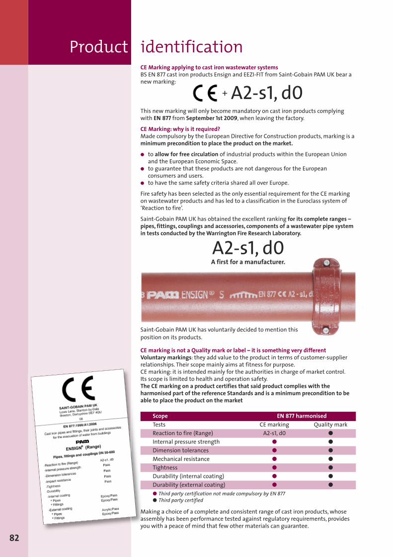
This newmarking will only becomemandatory on cast iron products complyingwith EN 877 from September 1st 2009, when leaving the factory.
CE Marking:why is it required?Made compulsory by the European Directive for Construction products,marking is aminimum precondition to place the product on the market.
� to allow for free circulation of industrial products within the European Unionand the European Economic Space.
� to guarantee that these products are not dangerous for the Europeanconsumers and users.
� to have the same safety criteria shared all over Europe.
Fire safety has been selected as the only essential requirement for the CE markingon wastewater products and has led to a classification in the Euroclass system of‘Reaction to fire’.
Saint-Gobain PAM UK has obtained the excellent ranking for its complete ranges –pipes, fittings, couplings and accessories, components of a wastewater pipe systemin tests conducted by theWarrington Fire Research Laboratory.
A2-s1, d0A first for a manufacturer.
CE marking is not a Quality mark or label – it is something very differentVoluntary markings: they add value to the product in terms of customer-supplierrelationships. Their scope mainly aims at fitness for purpose.CE marking: it is intended mainly for the authorities in charge of market control.Its scope is limited to health and operation safety.The CE marking on a product certifies that said product complies with theharmonised part of the reference Standards and is a minimum precondition to beable to place the product on the market
Product identification
82
+ A2-s1, d0
Saint-Gobain PAM UK has voluntarily decided to mention thisposition on its products.
Scope EN 877 harmonisedTests CE marking Quality markReaction to fire (Range) A2-s1, d0 �
Internal pressure strength � �
Dimension tolerances � �
Mechanical resistance � �
Tightness � �
Durability (internal coating) � �
Durability (external coating) � �
� Third party certification not made compulsory by EN 877� Third party certified
Making a choice of a complete and consistent range of cast iron products, whoseassembly has been performance tested against regulatory requirements, providesyou with a peace of mind that few other materials can guarantee.
CE Marking applying to cast iron wastewater systemsBS EN 877 cast iron products Ensign and EEZI-FIT from Saint-Gobain PAM UK bear anewmarking:
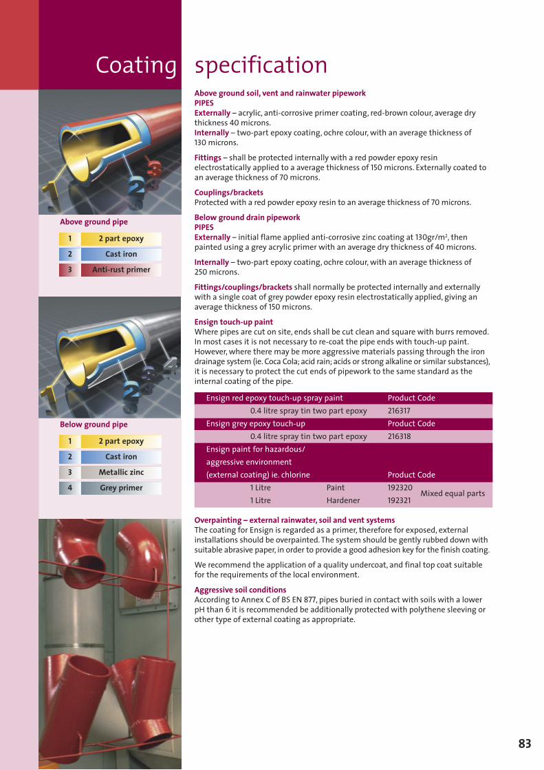
Coating specificationAbove ground soil, vent and rainwater pipeworkPIPESExternally – acrylic, anti-corrosive primer coating, red-brown colour, average drythickness 40microns.Internally – two-part epoxy coating, ochre colour,with an average thickness of130microns.
Fittings – shall be protected internally with a red powder epoxy resinelectrostatically applied to a average thickness of 150microns. Externally coated toan average thickness of 70microns.
Couplings/bracketsProtected with a red powder epoxy resin to an average thickness of 70microns.
Below ground drain pipeworkPIPESExternally – initial flame applied anti-corrosive zinc coating at 130gr/m2, thenpainted using a grey acrylic primer with an average dry thickness of 40microns.
Internally – two-part epoxy coating, ochre colour,with an average thickness of250microns.
Fittings/couplings/brackets shall normally be protected internally and externallywith a single coat of grey powder epoxy resin electrostatically applied, giving anaverage thickness of 150microns.
Ensign touch-up paintWhere pipes are cut on site, ends shall be cut clean and square with burrs removed.In most cases it is not necessary to re-coat the pipe ends with touch-up paint.However,where there may be more aggressive materials passing through the irondrainage system (ie. Coca Cola; acid rain; acids or strong alkaline or similar substances),it is necessary to protect the cut ends of pipework to the same standard as theinternal coating of the pipe.
Overpainting – external rainwater, soil and vent systemsThe coating for Ensign is regarded as a primer, therefore for exposed, externalinstallations should be overpainted.The system should be gently rubbed downwithsuitable abrasive paper, in order to provide a good adhesion key for the finish coating.
We recommend the application of a quality undercoat, and final top coat suitablefor the requirements of the local environment.
Aggressive soil conditionsAccording to Annex C of BS EN 877, pipes buried in contact with soils with a lowerpH than 6 it is recommended be additionally protected with polythene sleeving orother type of external coating as appropriate.
83
Above ground pipe
1 2 part epoxy
2 Cast iron
3 Anti-rust primer
Below ground pipe
1 2 part epoxy
2 Cast iron
3 Metallic zinc
4 Grey primer
Ensign red epoxy touch-up spray paint Product Code0.4 litre spray tin two part epoxy 216317
Ensign grey epoxy touch-up Product Code0.4 litre spray tin two part epoxy 216318
Ensign paint for hazardous/aggressive environment(external coating) ie. chlorine Product Code
1 Litre Paint 192320Mixed equal parts
1 Litre Hardener 192321
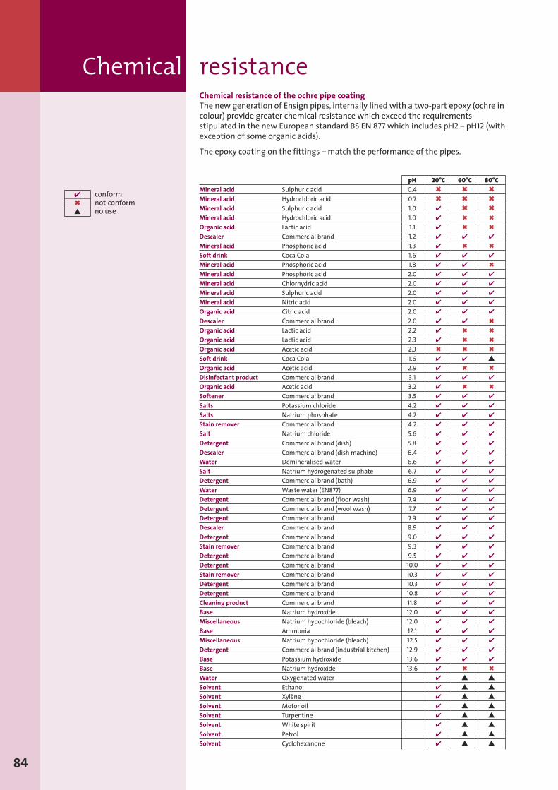
Chemical resistanceChemical resistance of the ochre pipe coatingThe new generation of Ensign pipes, internally lined with a two-part epoxy (ochre incolour) provide greater chemical resistance which exceed the requirementsstipulated in the new European standard BS EN 877which includes pH2 – pH12 (withexception of some organic acids).
The epoxy coating on the fittings – match the performance of the pipes.
84
pH 20°C 60°C 80°CMineral acid Sulphuric acid 0.4 � � �
Mineral acid Hydrochloric acid 0.7 � � �
Mineral acid Sulphuric acid 1.0 � � �
Mineral acid Hydrochloric acid 1.0 � � �
Organic acid Lactic acid 1.1 � � �
Descaler Commercial brand 1.2 � � �
Mineral acid Phosphoric acid 1.3 � � �
Soft drink Coca Cola 1.6 � � �
Mineral acid Phosphoric acid 1.8 � � �
Mineral acid Phosphoric acid 2.0 � � �
Mineral acid Chlorhydric acid 2.0 � � �
Mineral acid Sulphuric acid 2.0 � � �
Mineral acid Nitric acid 2.0 � � �
Organic acid Citric acid 2.0 � � �
Descaler Commercial brand 2.0 � � �
Organic acid Lactic acid 2.2 � � �
Organic acid Lactic acid 2.3 � � �
Organic acid Acetic acid 2.3 � � �
Soft drink Coca Cola 1.6 � � �
Organic acid Acetic acid 2.9 � � �
Disinfectant product Commercial brand 3.1 � � �
Organic acid Acetic acid 3.2 � � �
Softener Commercial brand 3.5 � � �
Salts Potassium chloride 4.2 � � �
Salts Natrium phosphate 4.2 � � �
Stain remover Commercial brand 4.2 � � �
Salt Natrium chloride 5.6 � � �
Detergent Commercial brand (dish) 5.8 � � �
Descaler Commercial brand (dish machine) 6.4 � � �
Water Demineralised water 6.6 � � �
Salt Natrium hydrogenated sulphate 6.7 � � �
Detergent Commercial brand (bath) 6.9 � � �
Water Waste water (EN877) 6.9 � � �
Detergent Commercial brand (floor wash) 7.4 � � �
Detergent Commercial brand (wool wash) 7.7 � � �
Detergent Commercial brand 7.9 � � �
Descaler Commercial brand 8.9 � � �
Detergent Commercial brand 9.0 � � �
Stain remover Commercial brand 9.3 � � �
Detergent Commercial brand 9.5 � � �
Detergent Commercial brand 10.0 � � �
Stain remover Commercial brand 10.3 � � �
Detergent Commercial brand 10.3 � � �
Detergent Commercial brand 10.8 � � �
Cleaning product Commercial brand 11.8 � � �
Base Natrium hydroxide 12.0 � � �
Miscellaneous Natrium hypochloride (bleach) 12.0 � � �
Base Ammonia 12.1 � � �
Miscellaneous Natrium hypochloride (bleach) 12.5 � � �
Detergent Commercial brand (industrial kitchen) 12.9 � � �
Base Potassium hydroxide 13.6 � � �
Base Natrium hydroxide 13.6 � � �
Water Oxygenated water � � �
Solvent Ethanol � � �
Solvent Xylène � � �
Solvent Motor oil � � �
Solvent Turpentine � � �
Solvent White spirit � � �
Solvent Petrol � � �
Solvent Cyclohexanone � � �
conformnot conformno use
���
Computer AidedDesign (CAD)
Sect
ion8
85
Ensign cast iron drainage 1stchoice for car parks
Ensign has the strength vital inareas where soil stacks arevulnerable to impact:
� secure – strong enough towithstand the knocks frommanoeuvring motor vehicles
� tough – also strong enough towithstand vandalism andwanton attack
� non-combustible – will not dripas molten, burning globules(unlike HDPE, UPVC),contributing to spread offire and threat of injury tothe public, staff andfirefighters alike
� requires minimal up-keep –helps keep maintenancecosts and disruption to anabsolute minimum
� durable – systems last in excessof 50 years
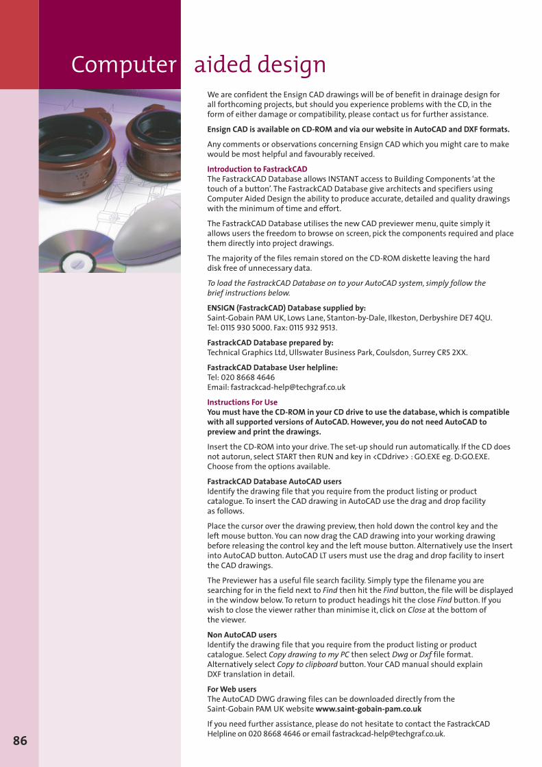
Computer aided design
86
We are confident the Ensign CAD drawings will be of benefit in drainage design forall forthcoming projects, but should you experience problems with the CD, in theform of either damage or compatibility, please contact us for further assistance.
Ensign CAD is available on CD-ROM and via our website in AutoCAD and DXF formats.
Any comments or observations concerning Ensign CAD which you might care to makewould be most helpful and favourably received.
Introduction to FastrackCADThe FastrackCAD Database allows INSTANT access to Building Components ‘at thetouch of a button’. The FastrackCAD Database give architects and specifiers usingComputer Aided Design the ability to produce accurate, detailed and quality drawingswith the minimum of time and effort.
The FastrackCAD Database utilises the new CAD previewer menu, quite simply itallows users the freedom to browse on screen, pick the components required and placethem directly into project drawings.
The majority of the files remain stored on the CD-ROM diskette leaving the harddisk free of unnecessary data.
To load the FastrackCAD Database on to your AutoCAD system, simply follow thebrief instructions below.
ENSIGN (FastrackCAD) Database supplied by:Saint-Gobain PAM UK, Lows Lane, Stanton-by-Dale, Ilkeston, Derbyshire DE7 4QU.Tel:0115 930 5000. Fax:0115 932 9513.
FastrackCAD Database prepared by:Technical Graphics Ltd, Ullswater Business Park, Coulsdon, Surrey CR5 2XX.
FastrackCAD Database User helpline:Tel: 020 8668 4646Email: [email protected]
Instructions For UseYou must have the CD-ROM in your CD drive to use the database,which is compatiblewith all supported versions of AutoCAD. However, you do not need AutoCAD topreview and print the drawings.
Insert the CD-ROM into your drive. The set-up should run automatically. If the CD doesnot autorun, select START then RUN and key in <CDdrive> : GO.EXE eg. D:GO.EXE.Choose from the options available.
FastrackCAD Database AutoCAD usersIdentify the drawing file that you require from the product listing or productcatalogue. To insert the CAD drawing in AutoCAD use the drag and drop facilityas follows.
Place the cursor over the drawing preview, then hold down the control key and theleft mouse button. You can now drag the CAD drawing into your working drawingbefore releasing the control key and the left mouse button. Alternatively use the Insertinto AutoCAD button. AutoCAD LT users must use the drag and drop facility to insertthe CAD drawings.
The Previewer has a useful file search facility. Simply type the filename you aresearching for in the field next to Find then hit the Find button, the file will be displayedin the window below.To return to product headings hit the close Find button. If youwish to close the viewer rather than minimise it, click on Close at the bottom ofthe viewer.
Non AutoCAD usersIdentify the drawing file that you require from the product listing or productcatalogue. Select Copy drawing to my PC then select Dwg or Dxf file format.Alternatively select Copy to clipboard button. Your CADmanual should explainDXF translation in detail.
ForWeb usersThe AutoCAD DWG drawing files can be downloaded directly from theSaint-Gobain PAM UK websitewww.saint-gobain-pam.co.uk
If you need further assistance, please do not hesitate to contact the FastrackCADHelpline on 020 8668 4646 or email [email protected].
Ensign standard specification1.1 Above ground soil,waste, vent and rainwater pipework.1.2 Cast iron pipes and fittings
a) The systems shall be designed and installed in accordance withBS EN 12056 code of practice for gravity drainage systemsinside buildings and the relevant sections of the BuildingRegulations.
b) Soil, vent and rainwater pipework of nominal diameters, 50mmto 600mm shall be installed using lightweight cast ironsocketless pipe and fittings which fully comply with allrequirements (27 clauses) of product standard BS EN 877:1999with kitemark third party approval.
c) Soil, vent and rainwater pipework shall have been tested toBS EN 14366:2004 (Laboratorymeasurement of noise of wastewater installations) by a recognised certified laboratory.Theresults to bemade available for review if required.
d) Soil, vent and rainwater pipework shall have a fire ratingA2, s1,d0**
Bracketse) Pipework shall be supported true to line bymethods strictly in
accordance with themanufacturer’s recommendations.Proprietary adjustable ductile iron hanging brackets such asEF048 or EF049 or EF048AD shall be used or brackets asrecommended by themanufacturer’s standard guidelines.
f) Soil, vent and rainwater pipework shall be supported byacoustic brackets that ensure the pipework will not exceed47dB (A) airborne noise and 11dB (A) structure-borne noise at4 l/s (litres per second),without insulation as recommended bythemanufacturer’s standard guidelines.
JointingStandard Couplingsg) Pipes and fittings up to 150mmdiameter shall be jointed by
couplings capable of withstanding up to 5bar (accidental staticwater pressure) when suitably restrained with supportbrackets. Pipes and fittings 200mm to 300mmdiameterjointed by couplings capable of withstanding up to 3bar(accidental static water pressure) when suitably restrainedwith support brackets. Couplings shall have integral electricalcontinuity nibs. Coupling colour shall match the pipes andfittings.
Push-fit Couplingsh) Pipes and fittings shall be jointed by push-fit couplings
incorporating 2 EPDM gaskets.Meeting requirements of BS EN877:1999. Coupling colour shall match the pipes and fittings.
High Pressure Couplings with Integral Gripi) Unrestrained Pipes and fittings shall be jointed by couplings
capable of withstanding 5bar (accidental static water pressure)as supplied by themanufacturer (these do not requirerestraining brackets).
Fittingsj) Where required to connect to low level soil pipework passing
through the floor slab, use long tail radius curve branches at 88degrees (conforming to BS EN 12056-2:2000) to connect to100mm soil andwaste pipes where applicable, therebyavoiding a joint in the floor slab.
k) Where possible all 88 degree branches shall be radius curveentry (conforming to BS EN 12056-2:2000).
l) Small diameter waste pipes in plastic or copper to beconnected to themain soil pipework using either mechanicalcompression-fit or BSP threaded boss pipes, or push-fitmanifolds with grommets or blank ends.
Cutting Pipesm) Where pipes are cut on site, ends shall be cut clean and square
with all burrs removed. Inmost cases it is not necessary tore-coat the pipe ends with“touch-up paint”.However,wheretheremay be aggressivematerials passing through thedrainage system (i.e. Coca-Cola; acid rain; acids or strongalkaline or similar substances), it is necessary to protect the cutends of the pipework to the same standard as the internalcoating of the pipe (as recommended by themanufacturer).
Coatingn) Pipes shall be externally coated with an acrylic, anti-corrosion
primer coating, red-brown in colour, average dry thickness of40microns. Internally coated with a two-part epoxy coating,ochre colour,with an average thickness of 130microns.
o) Fittings shall be protected internally with a red powder epoxyresin electrostatically applied to an average thickness of 150microns. Externally coated to an average thickness of 70microns.
p) Couplings/brackets shall be protected with a red powder epoxyresin applied to an average thickness of 70microns.
References:-**EN 13501-1November 2002 Fire classification of constructionproducts and building elements.
1.1 Below ground buried foul and stormwater pipework.1.2 Cast iron pipes and fittings
a) The systems shall be designed and installed in accordance withBS EN 12056 code of practice for gravity drainage systemsinside buildings, BS EN 752-1 for drain and sewer systemsoutside buildings and the relevant sections of the BuildingRegulations.
b) Foul and stormwater pipework of nominal diameters, 100, 150to 600mm shall be installed using lightweight cast ironsocketless pipe and fittings which fully comply with all relevantrequirements of product standard BS EN 877:1999withkitemark third party approval.
Bracketsc) Pipework shall be supported true to line bymethods strictly in
accordance with themanufacturer’s recommendations.Proprietary adjustable ductile iron hanging brackets as ED048shall be used or brackets as recommended by themanufacturer’s standard guidelines.
JointingStandard Couplingsd) Pipes and fittings up to 150mmdiameter shall be jointed by
couplings capable of withstanding up to bar (accidental staticwater pressure) when suitably restrained with supportbrackets. Pipes and fittings 200mm to 300mmdiameterjointed by couplings capable of withstanding up to 3bar(accidental static water pressure) when suitably restrainedwith support brackets. Coupling colour shall match the pipesand fittings, and incorporate stainless steel socket cap screwsand nuts wax coated.
Push-fit Couplingse) Pipes and fittings 100 and 150mmdiameter shall be jointed by
push-fit couplings incorporating 2 EPDM gaskets.Meetingrequirements of BS EN 877:1999. Coupling colour shall matchthe pipes and fittings.
High Pressure Couplings with Integral Gripf) Unrestrained pipes and fittings shall be jointed by couplings
capable of withstanding 5bar (accidental static water pressure)as supplied by themanufacturer (these do not requirerestraining brackets).
Fittingsg) Connection to small diameter waste and ventilating pipework
or other materials shall bemade using blank ends using push-fit connection or proprietary fittings.
h) Junctions between pipes should use the proprietary cast ironchamber, or standard branch type fittings as recommended bythemanufacturer
Cutting Pipesi) Where pipes are cut on site, ends shall be cut clean and square
with all burrs removed. Inmost cases it is not necessary tore-coat the pipe ends with“touch-up paint”.However,wheretheremay be aggressivematerials passing through thedrainage system (i.e. Coca-Cola; acid rain; acids or strongalkaline or similar substances), it is necessary to protect the cutends of the pipework to the same standard as the internalcoating of the pipe (as recommended by themanufacturer).
Coatingj) Pipes shall be externally coated with an initial flame applied
anti-corrosive zinc coating at 130gr/m2 then painted using agrey acrylic primer with an average thickness of 40microns.Internally coated with a two-part epoxy coating, ochre incolour,with an average thickness of 250microns.
k) Fittings/ couplings/ brackets shall be protected internally andexternally with a single coat of grey powder epoxy resinelectrostatically applied to an average thickness of 150microns.
87
88
EEZI-FIT specificationEnsign1.1 Above ground soil and vent pipework.1.2 Cast iron pipes and fittings
a) The systems shall be designed and installed in accordance withBS EN 12056 code of practice for gravity drainage systemsinside buildings and the relevant sections of the BuildingRegulations.
b) Soil and vent pipework of nominal diameters, 100mm to150mm shall be installed using lightweight cast iron socketlesspipe and fittings which fully comply with all requirements (27clauses) of product standard BS EN 877:1999with Kitemarkthird party approval.
c) Soil and vent pipework shall have been tested toBS EN 14366:2004 (Laboratorymeasurement of noise of wastewater installations) by a recognised certified laboratory.
d) Soil and vent pipework shall have a fire rating A2, s1, d0**Bracketse) Soil and vent pipework shall be supported by acoustic brackets
that ensure the pipework will not exceed 47dB (A) airbornenoise and 11dB (A) structure-borne noise at 4 l/s (litres persecond),without insulation as recommended by themanufacturer’s standard guidelines.
f) Pipework shall be supported true to line bymethods strictly inaccordance with themanufacturer’s recommendations.Proprietary adjustable ductile iron hanging brackets such asEF048 or EF049 or EF048AD shall be used or brackets asrecommended by themanufacturer’s standard guidelines.
JointingPush-fit Couplingsg) Pipes and fittings shall be jointed by EEZI-FIT couplings
incorporating 2 EPDM push-fit gaskets using suitable lubricantas recommended by themanufacturer.The couplings shallmeet with the requirements of BS EN 877:1999. Coupling colourshall match the pipes and fittings.
Mechanical Couplingsh) Pipes and fittings up to 100mmdiameter shall be jointed by
couplings capable of withstanding up to 1.0bar when suitablysupported. Couplings shall have integral electrical continuitynibs. Coupling colour shall match the pipes and fittings. (Thesecouplings can be used in areas where future dismantlingmaybe required).
Fittingsi) EEZI-FIT soil pipework shall be installed using fittings that
incorporate the jointing socket with integral EPDM push-fitgasket using suitable lubricant as recommended by themanufacturer.
j) Where possible all 88 degree branches shall be radius curveentry.
k) Small diameter waste pipes in plastic or copper to beconnected to themain soil pipework using fittings which haveintegral bosses that can be cut out to suit the installation (with51mmhole saw), push-fit boss pipes, or push-fit manifolds withgrommets or blank ends.
Electrical Continuityl) On pipework installations where electrical conductivity
(equipotential bonding) is required, continuity clips shallbe installed.
Cutting Pipesm) Where pipes are cut on site, ends shall be cut clean and square
with all burrs removed. Inmost cases it is not necessary tore-coat the pipe ends with“touch-up paint”.However,wheretheremay be aggressivematerials passing through thedrainage system (i.e. Coca-Cola; acid rain; acids or strongalkaline or similar substances), it is necessary to protect the cutends of the pipework to the same standard as the internalcoating of the pipe (as recommended by themanufacturer).
Coatingn) Pipes shall be externally coated with an acrylic, anti-corrosion
primer coating, red-brown in colour, average dry thickness of40microns. Internally coated with a two-part epoxy coating,ochre colour,with an average thickness of 130microns.
o) Fittings shall be protected internally with a red powder epoxyresin electrostatically applied to an average thickness of 150microns. Externally coated to an average thickness of 70microns.
p) Couplings/brackets shall be protected with a red powder epoxyresin applied to an average thickness of 70microns
References:-**EN 13501-1November 2002 Fire classification ofconstruction products and building elements.