Embed Size (px)
Citation preview
Absolute-length determination of a long-baselineFabry–Perot cavity by means of resonatingmodulation sidebands
Akito Araya, Souichi Telada, Kuniharu Tochikubo, Shinsuke Taniguchi,Ryutaro Takahashi, Keita Kawabe, Daisuke Tatsumi, Toshitaka Yamazaki,Seiji Kawamura, Shinji Miyoki, Shigenori Moriwaki, Mitsuru Musha, Shigeo Nagano,Masa-Katsu Fujimoto, Kazuo Horikoshi, Norikatsu Mio, Yutaka Naito,Akiteru Takamori, and Kazuhiro Yamamoto
A new method has been demonstrated for absolute-length measurements of a long-baseline Fabry–Perotcavity by use of phase-modulated light. This method is based on determination of a free spectral range~FSR! of the cavity from the frequency difference between a carrier and phase-modulation sidebands, bothof which resonate in the cavity. Sensitive response of the Fabry–Perot cavity near resonant frequenciesensures accurate determination of the FSR and thus of the absolute length of the cavity. This methodwas applied to a 300-m Fabry–Perot cavity of the TAMA gravitational wave detector that is beingdeveloped at the National Astronomical Observatory, Tokyo. With a modulation frequency of ;12 MHz,we successfully determined the absolute cavity length with resolution of 1 mm ~3 3 1029 in strain! andobserved local ground strain variations of 6 3 1028. © 1999 Optical Society of America
OCIS codes: 120.2230, 120.3180, 120.3940, 120.5060.
1
tn
mm
mp
1. Introduction
Laser interferometers are widely used for precisemeasurements and are used to determine absolutelengths by referring to the wavelength of light. Forshort length measurements of several meters or less,several kinds of standard frequency-stabilized laser
A. Araya [email protected]! is with the Earthquake Re-search Institute, University of Tokyo, 1-1-1, Yayoi, Bunkyo, Tokyo113-0032, Japan. S. Telada, R. Takahashi, T. Yamazaki, S.Kawamura, and M.-K. Fujimoto are with the National Astronom-ical Observatory, 2-21-1, Osawa, Mitaka, Tokyo 181-8588, Japan.D. Tatsumi, S. Miyoki, and S. Nagano are with the Institute forCosmic Ray Research, University of Tokyo, 3-2-1, Midori-cho, Ta-nashi, Tokyo 188-8502, Japan. S. Moriwaki and N. Mio are withthe Department of Applied Physics, University of Tokyo, 7-3-1,Hongo, Bunkyo, Tokyo 113-8656, Japan. M. Musha is with theInstitute for Laser Science, University of Electro-Communications,1-5-1, Chofugaoka, Chofu, Tokyo 182-8585, Japan. S. Nagano,M. K. Fujimoto, K. Horikoshi, N. Mio, Y. Naito, A. Takamori, andK. Yamamoto are with the Department of Physics, University ofTokyo, 7-3-1, Hongo, Bunkyo, Tokyo 113-0033, Japan.
Received 17 November 1998; revised manuscript received 5 Feb-ruary 1999.
0003-6935y99y132848-09$15.00y0© 1999 Optical Society of America
2848 APPLIED OPTICS y Vol. 38, No. 13 y 1 May 1999
can be used as references. For long-distance mea-surements ~more than ;10 m!, however, it is difficulto determine absolute length because of the largeumber of fringes that must be counted.2 Instead, a
radio frequency ~RF! or microwave modulationmethod is usually used for these measurements.3 Inthis method the laser light is modulated in intensitywith RF or microwaves, and the distance can be de-termined from the phase difference between the in-cident and the returned ~round-trip! light.
Here we estimate the accuracy of the RF–icrowave modulation method. Assuming that theodulation frequency is nm and the phase difference
between the incident and the returned light is f, theabsolute length L can be expressed as
L 5c
2nmS f
2p1 ND , (1)
where c is the speed of light and N is the number ofodulation wavelengths in the round-trip optical
ath.4 The number N can be obtained either fromthe phase response to the change in nm ~Ref. 5! orfrom other indirect measurements. For known N,

r
c
tu
pipcsttlcqim
mmFa
n
s
1Frp
the final accuracy ~dL! is determined by the phaseesolution ~df! as
dL 5c
2nm
df
2p
5lm
2a, (2)
where lm ~5cynm! is the wavelength for the modula-tion frequency and a ~5dfy2p! is a fractional resolu-tion for phase detection. Because a tends to be atbest 1024–1025 regardless of the modulation frequen-y,5 better resolution requires higher modulation fre-
quencies.6 However, a higher modulation frequencymakes it more difficult to determine N. Moreover,here are practical limitations to the use of high mod-lation frequencies.The method that we describe in this paper im-
roves the phase resolution effectively withoutncreasing modulation frequencies. It utilizeshase-modulated light and an optical Fabry–Perotavity, which enhances the phase sensitivity of theystem. By adjusting the modulation frequency ofhe incident light such that the sidebands resonate inhe cavity, we can determine the absolute cavityength from the modulation wavelength. A sharpavity resonance serves to tune the modulation fre-uency precisely to the center of the resonance, lead-ng to excellent distance resolution, even with a low
odulation frequency.In this paper, discussion of the principle of theethod is followed by the description of an experi-ent on absolute-length measurement with a 300-mabry–Perot cavity. Finally, attainable resolutionsre estimated and a possible application is discussed.
2. Principle
A. Properties of a Fabry–Perot Cavity
Here the fundamental properties of a Fabry–Perotcavity are summarized. For a Fabry–Perot cavityformed by two concave mirrors with radii of curva-ture R1 and R2, respectively, the resonant frequen-cies of the cavity are expressed as
nn 5c
2L Hn 11p
cos21@~1 2 LyR1!~1 2 LyR2!#1y2J (3)
for the TEM00 mode, where L is the cavity length andis an integer.7 Therefore the free spectral range
~FSR! of the cavity, i.e., the frequency interval be-tween adjacent longitudinal resonances, is
nFSR 5 nn11 2 nn 5 cy2L, (4)
from which we can determine the absolute cavitylength L. The finesse of the cavity, defined as theratio of the FSR to the full width at half-maximumfrequency of the resonance, is given by
^ 5pÎr1r2
1 2 r1 r2, (5)
where r1 and r2 are the amplitude reflectances of theinput and the end mirrors, respectively. We assumethat r1
2 1 t12 5 1 and r2
2 1 t22 5 1, where t1 and t2
are the amplitude transmittances of the input andthe end mirrors, respectively. Writing the incidentlight as A0 exp~ivt!, we can calculate the cavity re-flected light as
Ar 5 Fr1 2t1
2r2 exp~22ivLyc!
1 2 r1 r2 exp~22ivLyc!G A0 exp~ivt!
; FFP A0 exp~ivt!, (6)
where, for simplicity, we have assumed plane wavesincident upon a flat-mirror cavity. At the center of aresonance, FFP becomes a real number, so its imag-inary part can be interpreted as a deviation from thecenter of the resonance. Phase-sensitive detectionmethods, such as the Pound–Drever–Hall method,8can sense the imaginary part of FFP ~I@FFP#!. Nearresonance, it can be approximated as
I@FFP# .r2~1 2 r1
2!
~1 2 r1 r2!2 S2L
c D2pdn, (7)
where dn is the detuning from the center of the res-onance.
It can be demonstrated that a Fabry–Perot cavityimproves phase resolution effectively. If the inci-dent light is modulated with a RF–microwave fre-quency of nm and the cavity length is detected withreference to the modulation, the following correspon-dence between the change in the modulation fre-quency ~dnm! and that in the cavity length ~dL! isatisfied:
dnmynm 5 dLyL. (8)
Replacing dn with dnm, we can rewrite relation ~7! as
dL .~1 2 r1 r2!
2
r2~1 2 r12! S c
2nmD df
2p, (9)
where we identify I@FFP# as df, assuming a smallphase change near the resonance. Comparing rela-tion ~9! with Eq. ~2! for a simple round-trip opticalpath, we can conclude that the Fabry–Perot cavityenhances the sensitivity by a factor of
r2~1 2 r12!
~1 2 r1 r2!2 .
e^
p Se 51 2 r1
2
1 2 r1 r2D . (10)
The approximation is valid for a high-finesse cavity,i.e., r1 . 1 and r2 . 1. If r2 is nearly equal to r1, e .. From these estimations, if we use a high-finesseabry–Perot cavity of similar-reflectance mirrors, theesolution of absolute length measurements is ex-ected to be improved by a factor of ^yp.
B. Carrier and Sideband Locking
Here we explain the principle of the length-measurement system with a Fabry–Perot cavity. Asis shown in Eq. ~4!, absolute cavity length is deter-mined from the FSR of the cavity. It can be obtained
1 May 1999 y Vol. 38, No. 13 y APPLIED OPTICS 2849
Te
sk
2
from the frequency difference between two spectralcomponents, which are the nth- and the ~n 1 1!th-order resonance of the cavity, respectively. The twospectral components are produced by application ofphase modulation to the incident light. With a mod-ulation index of Df and a modulation angular fre-quency of vm ~52pnm!, the resultant spectralcomponents are expressed in terms of Bessel func-tions ~Jk! as
A0 exp@i~vt 1 Df sin vm t!#
5 A0 (k52`
`
Jk~Df!exp@i~v 1 kvm!t#
. A0(J0~Df!exp~ivt!
1 J1~Df!$exp@i~v 1 vm!t#
2 exp@i~v 2 vm!t#%), (11)
where the last expression assumes a small modula-tion index ~Df ,, 1! and the two lowest-order side-bands dominate in power. When the carrierfrequency is adjusted to the nth-order resonance ofthe cavity and the two dominant sideband compo-nents are adjusted to the ~n 1 m!th- and the ~n 2m!th-order resonances ~m and n are integers!, themodulation frequency ~vmy2p! corresponds to mtimes the FSR of the cavity. This method requirestwo locking procedures: carrier locking to an nthresonance and sideband locking to the ~n 6 m!thresonances.
Carrier locking can be realized by the Pound–Drever–Hall method. This method requires an ad-ditional phase modulation to detect the phase changeof the carrier near the resonance. The frequency ofthe phase modulation for the carrier locking shouldbe set such that the resultant sidebands are suffi-ciently apart from the cavity resonant frequencies;otherwise these sidebands would not work as refer-ences for the detection of the carrier phase changes.
Sideband locking is accomplished by a novel tech-nique involving double demodulation. When thecavity reflected light signal is demodulated at thefrequency of the FSR-measuring modulation, the re-sultant signal has the form
16A02J0~Df!J1~Df!
3r1 r2 t1
2@1 2 r22~r1
2 1 t12!#
~1 2 r1 r2!4 SL
cD2
DvDvm
. 8A02Df
t12t2
2
~1 2 r1 r2!2 ^2 DnDnm
nFSR2 . (12)
he demodulated signal depends on both the differ-nce of the carrier frequency from the nth resonance
~Dn! and the difference of the sideband frequencyfrom m 3 FSR ~Dnm!.9 Under the condition thatcarrier frequency n is precisely locked at the center ofthe cavity resonance, the reflected light contains nosignals for locking the sideband frequency. To ob-tain the sideband-locking signal we intentionally
850 APPLIED OPTICS y Vol. 38, No. 13 y 1 May 1999
cause a deviation by modulating the carrier fre-quency about the resonance center by a smallamount:
Dn 5 Dnn sin vn t ~Dnn ,, nFSRy^!. (13)
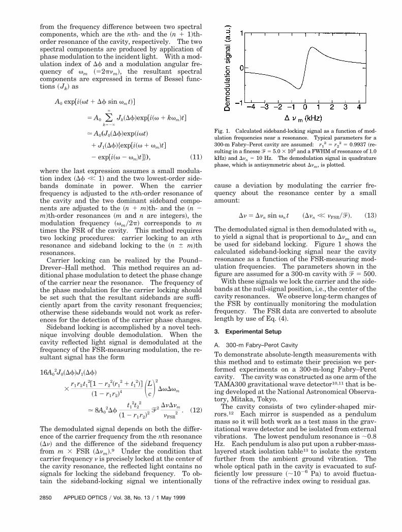
The demodulated signal is then demodulated with vnto yield a signal that is proportional to Dnm and canbe used for sideband locking. Figure 1 shows thecalculated sideband-locking signal near the cavityresonance as a function of the FSR-measuring mod-ulation frequencies. The parameters shown in thefigure are assumed for a 300-m cavity with ^ 5 500.
With these signals we lock the carrier and the side-bands at the null-signal position, i.e., the center of thecavity resonances. We observe long-term changes ofthe FSR by continually monitoring the modulationfrequency. The FSR data are converted to absolutelength by use of Eq. ~4!.
3. Experimental Setup
A. 300-m Fabry–Perot Cavity
To demonstrate absolute-length measurements withthis method and to estimate their precision we per-formed experiments on a 300-m-long Fabry–Perotcavity. The cavity was constructed as one arm of theTAMA300 gravitational wave detector10,11 that is be-ing developed at the National Astronomical Observa-tory, Mitaka, Tokyo.
The cavity consists of two cylinder-shaped mir-rors.12 Each mirror is suspended as a pendulummass so it will both work as a test mass in the grav-itational wave detector and be isolated from externalvibrations. The lowest pendulum resonance is ;0.8Hz. Each pendulum is also put upon a rubber-mass-layered stack isolation table13 to isolate the systemfurther from the ambient ground vibration. Thewhole optical path in the cavity is evacuated to suf-ficiently low pressure ~;1026 Pa! to avoid fluctua-tions of the refractive index owing to residual gas.
Fig. 1. Calculated sideband-locking signal as a function of mod-ulation frequencies near a resonance. Typical parameters for a300-m Fabry–Perot cavity are assumed: r1
2 5 r22 5 0.9937 ~re-
ulting in a finesse ^ 5 5.0 3 102 and a FWHM of resonance of 1.0Hz! and Dnn 5 10 Hz. The demodulation signal in quadrature
phase, which is antisymmetric about Dnm, is plotted.
~
sc
wq
cbp
B. Measurement Scheme
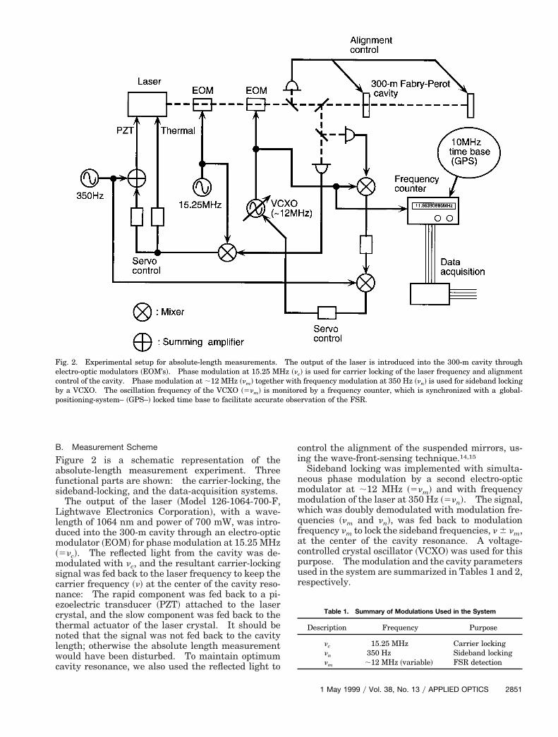
Figure 2 is a schematic representation of theabsolute-length measurement experiment. Threefunctional parts are shown: the carrier-locking, thesideband-locking, and the data-acquisition systems.
The output of the laser ~Model 126-1064-700-F,Lightwave Electronics Corporation!, with a wave-length of 1064 nm and power of 700 mW, was intro-duced into the 300-m cavity through an electro-opticmodulator ~EOM! for phase modulation at 15.25 MHz5nc!. The reflected light from the cavity was de-
modulated with nc, and the resultant carrier-lockingignal was fed back to the laser frequency to keep thearrier frequency ~n! at the center of the cavity reso-
nance: The rapid component was fed back to a pi-ezoelectric transducer ~PZT! attached to the lasercrystal, and the slow component was fed back to thethermal actuator of the laser crystal. It should benoted that the signal was not fed back to the cavitylength; otherwise the absolute length measurementwould have been disturbed. To maintain optimumcavity resonance, we also used the reflected light to
Fig. 2. Experimental setup for absolute-length measurements.electro-optic modulators ~EOM’s!. Phase modulation at 15.25 MHontrol of the cavity. Phase modulation at ;12 MHz ~nm! togethey a VCXO. The oscillation frequency of the VCXO ~5nm! is moositioning-system– ~GPS–! locked time base to facilitate accurate
control the alignment of the suspended mirrors, us-ing the wave-front-sensing technique.14,15
Sideband locking was implemented with simulta-neous phase modulation by a second electro-opticmodulator at ;12 MHz ~5nm! and with frequencymodulation of the laser at 350 Hz ~5nn!. The signal,
hich was doubly demodulated with modulation fre-uencies ~nm and nn!, was fed back to modulation
frequency nm to lock the sideband frequencies, n 6 nm,at the center of the cavity resonance. A voltage-controlled crystal oscillator ~VCXO! was used for thispurpose. The modulation and the cavity parametersused in the system are summarized in Tables 1 and 2,respectively.
output of the laser is introduced into the 300-m cavity throughc! is used for carrier locking of the laser frequency and alignment
frequency modulation at 350 Hz ~nn! is used for sideband lockinged by a frequency counter, which is synchronized with a global-rvation of the FSR.
Table 1. Summary of Modulations Used in the System
Description Frequency Purpose
nc 15.25 MHz Carrier lockingnn 350 Hz Sideband lockingnm ;12 MHz ~variable! FSR detection
Thez ~n
r withnitorobse
1 May 1999 y Vol. 38, No. 13 y APPLIED OPTICS 2851
1
wmt
oMlroae3fcl
tiaicF
Table 2. Parameters of the 300-m Fabry–Perot Cavity
2
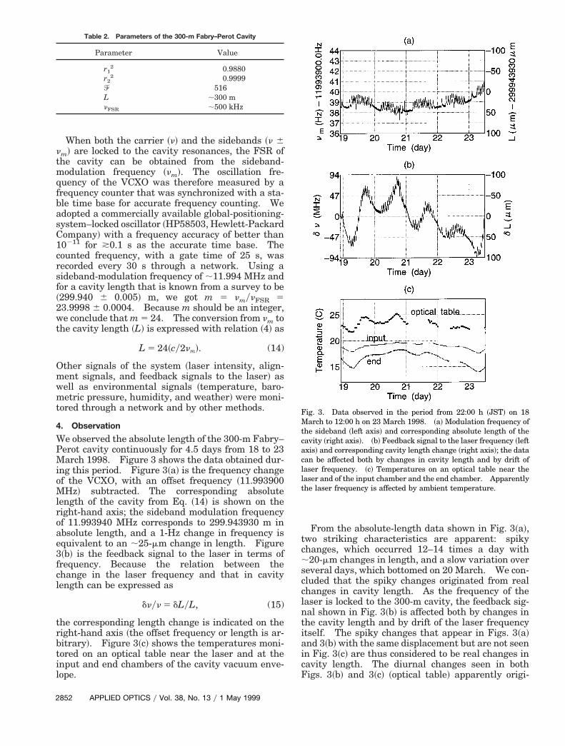
When both the carrier ~n! and the sidebands ~n 6nm! are locked to the cavity resonances, the FSR ofthe cavity can be obtained from the sideband-modulation frequency ~nm!. The oscillation fre-quency of the VCXO was therefore measured by afrequency counter that was synchronized with a sta-ble time base for accurate frequency counting. Weadopted a commercially available global-positioning-system–locked oscillator ~HP58503, Hewlett-PackardCompany! with a frequency accuracy of better than0211 for *0.1 s as the accurate time base. The
counted frequency, with a gate time of 25 s, wasrecorded every 30 s through a network. Using asideband-modulation frequency of ;11.994 MHz andfor a cavity length that is known from a survey to be~299.940 6 0.005! m, we got m 5 nmynFSR 523.9998 6 0.0004. Because m should be an integer,we conclude that m 5 24. The conversion from nm tothe cavity length ~L! is expressed with relation ~4! as
L 5 24~cy2nm!. (14)
Other signals of the system ~laser intensity, align-ment signals, and feedback signals to the laser! as
ell as environmental signals ~temperature, baro-etric pressure, humidity, and weather! were moni-
ored through a network and by other methods.
4. Observation
We observed the absolute length of the 300-m Fabry–Perot cavity continuously for 4.5 days from 18 to 23March 1998. Figure 3 shows the data obtained dur-ing this period. Figure 3~a! is the frequency changef the VCXO, with an offset frequency ~11.993900Hz! subtracted. The corresponding absolute
ength of the cavity from Eq. ~14! is shown on theight-hand axis; the sideband modulation frequencyf 11.993940 MHz corresponds to 299.943930 m inbsolute length, and a 1-Hz change in frequency isquivalent to an ;25-mm change in length. Figure~b! is the feedback signal to the laser in terms ofrequency. Because the relation between thehange in the laser frequency and that in cavityength can be expressed as
dnyn 5 dLyL, (15)
the corresponding length change is indicated on theright-hand axis ~the offset frequency or length is ar-bitrary!. Figure 3~c! shows the temperatures moni-tored on an optical table near the laser and at theinput and end chambers of the cavity vacuum enve-lope.
Parameter Value
r12 0.9880
r22 0.9999
^ 516L ;300 mnFSR ;500 kHz
852 APPLIED OPTICS y Vol. 38, No. 13 y 1 May 1999
From the absolute-length data shown in Fig. 3~a!,two striking characteristics are apparent: spikychanges, which occurred 12–14 times a day with;20-mm changes in length, and a slow variation overseveral days, which bottomed on 20 March. We con-cluded that the spiky changes originated from realchanges in cavity length. As the frequency of thelaser is locked to the 300-m cavity, the feedback sig-nal shown in Fig. 3~b! is affected both by changes inhe cavity length and by drift of the laser frequencytself. The spiky changes that appear in Figs. 3~a!nd 3~b! with the same displacement but are not seenn Fig. 3~c! are thus considered to be real changes inavity length. The diurnal changes seen in bothigs. 3~b! and 3~c! ~optical table! apparently origi-
Fig. 3. Data observed in the period from 22:00 h ~JST! on 18March to 12:00 h on 23 March 1998. ~a! Modulation frequency ofthe sideband ~left axis! and corresponding absolute length of thecavity ~right axis!. ~b! Feedback signal to the laser frequency ~leftaxis! and corresponding cavity length change ~right axis!; the datacan be affected both by changes in cavity length and by drift oflaser frequency. ~c! Temperatures on an optical table near thelaser and of the input chamber and the end chamber. Apparentlythe laser frequency is affected by ambient temperature.

fvrrotspsooati
Fdztas
ttbplpasslcvne
nated from the drift of the laser frequency at roomtemperature.
We also concluded that the spiky changes origi-nated from regional ground strain changes ratherthan from local displacement of the mirrors. Wearrived at this conclusion because we found no spikyfeature in the tilt of the mirror suspension system,judging from the alignment signals, and a strong cor-relation between the spikes and the pumping ofgroundwater near the National Astronomical Obser-vatory campus ~the pumping well is located ;200 mrom the instrument!.16 Figure 4~a! is a magnifiediew of Fig. 3~a!. The shape of the spikes shows aapid rise ~shrinkage in length! within 30 min and aelaxation ~expansion in length! with a time constantf 1–2 h. Figure 4~b! shows the correlation betweenhese spikes and the pumping status; the groundhrinks when the pump is on, and it relaxes after theump is turned off. This behavior is intuitively con-istent with the response of the Earth to the pumpingf groundwater. It should be noted that the amountf strain caused by the pumping of groundwater wast a reasonable level according to Ref. 17. A map ofhe 300-m Fabry–Perot cavity and the pumping wells shown in Fig. 5.
As for the slow variation of the absolute length inig. 3~a!, we believe that it is dominated by localisplacement of the mirrors owing to tilt and hori-ontal drift of the isolation stacks caused by ambient-emperature fluctuations. After performing thebsolute-length experiment we measured the re-ponse of tilt–horizontal drift of the isolation stacks
Fig. 4. ~a! Magnified view of spiky changes in Fig. 3~a!. ~b! Syn-chronous observation of absolute length ~length! and pumping sta-tus ~pump!. The rise of a spiky change ~i.e., shrinkage in thecavity length! exactly agrees with the pumping of groundwater.
o the ambient temperature; we found that typicalemperature variations ~3° peak to peak! in the cham-ers could produce a mirror displacement of 50 mmeak to peak, the level observed in the absolute-ength measurement. Moreover, the recorded tem-erature variations in the chambers during thebsolute-length measurement @Fig. 3~c!# showed aimilar trend ~a peak on 20 March and a rather steeplope afterward! to the slow variation of the absoluteength. It should be noted that this slow variationompletely dominates tidal or semidiurnal–diurnalariations, which we had expected would be domi-ant and were interested in before we performed thexperiment.
5. Discussion
The resolution for the absolute-length measurementcan be evaluated from relations ~9! and ~10! as
dL ,lm
2p
e^a, (16)
where in our experiment lm 5 25 m, ^ 5 516, and e5 1.98. From Fig. 4~a! the resolution is approxi-mately dL 5 1 mm, which corresponds to a typicalphase resolution of a 5 2.6 3 1025. The resolutiondepends on several factors, such as ground vibration,the gate time for sideband frequency counting, themodulation parameters ~Dnn, vn!, and electronicsnoise in the sideband locking. Moreover, we usedsuspended mirrors, which have large pendulum mo-tions. The effect of ground vibration would be re-duced if suspended mirrors were replaced withmirrors fixed to the ground.
Fig. 5. Locations of the 300-m Fabry–Perot cavity and the pump-ing well. The distance from the center of the cavity to the well is;200 m.
1 May 1999 y Vol. 38, No. 13 y APPLIED OPTICS 2853
c
oc
ae
ctiabs
2
Here we discuss how to choose a modulation fre-quency ~nm! to attain the best accuracy. For simplic-ity, we assume that the accuracy is determined byphase resolution a and stability of modulation fre-quency b 5 dnmynm and that they are independent ofnm. A higher modulation frequency gives better dis-tance accuracy. However, too high a modulation fre-quency causes ambiguity in the number ofwavelength in the cavity ~N!. Although there areseveral methods to determine N,18 we discuss oneonvenient method for measuring the FSR.
By measuring the sideband frequency at the centerf a resonance and that of the adjacent resonance wean calculate the cavity length as
L 5 cy2~nm1 2 nm2!, (17)
where nm1 and nm2 ~,nm1! are modulation frequen-cies for the respective resonances. The number ofwavelengths for nm1 is expressed as
N 5 nm1y~nm1 2 nm2!. (18)
Here we address the uncertainties in nm1 and nm2,which determine the accuracy of N and may limit thehighest modulation frequency for determination ofthe absolute length. These uncertainties arise bothfrom the accuracy of modulation frequencies andfrom the accuracy of locking to the center of a reso-nance. The former is determined by relative fre-quency stability b as
dnfreq , bnm1; (19)
the latter is calculated from relations ~7! and ~10!with a:
dnlock ,c
2Lp
e^a. (20)
Then Eq. ~18! involves an ambiguity expressed ap-proximately as
N .nm1
nm1 2 nm26
nm1
~nm1 2 nm2!2 max~dnfreq, dnlock!.
(21)
To enable integer N to be determined without anyambiguity, the absolute value of the second term inexpression ~21! should be much smaller than unity.Assuming that the second term is smaller than g~,,1!, the modulation frequency should satisfy
nm1 & minFÎg
b,e^g
pa G c2L
(22)
for N to be unambiguously determined, where we useexpressions ~19! and ~20!. With the above limit, theccuracy of the absolute-distance measurements isvaluated from expressions ~9! and ~10!:
dL ,c
2nm1
p
e^a. (23)
854 APPLIED OPTICS y Vol. 38, No. 13 y 1 May 1999
Let us estimate the accuracy dL for various caseswith conservative parameters: g 5 0.1, b 5 10210, a5 1024. For a low-finesse cavity ~e^yp & ay=bg ;30!, locking uncertainty limits the modulation fre-quency to
nm1 &e^g
pa
c2L
. (24)
With maximum modulation frequency, the accuracyis calculated from expressions ~23! and ~24!:
dL ,p2
e2^2
a2
gL. (25)
If we apply expression ~25! to a simple round trip~e^yp 5 1!, the accuracy is relatively poor ~dL ;1027L!, even with a high modulation frequency ~e.g.,nm1 5 1.5 GHz for L 5 100 m!. As the finesse of theavity increases, the accuracy significantly improves;his is so because the high-finesse cavity not onlymproves the phase resolution @expression ~23!# butlso permits us to use a higher modulation frequencyecause of a reduction in locking uncertainty @expres-ion ~20!#: e.g., dL ; 10210 L for e^yp 5 30, nm1 5
45 GHz, and L 5 100 m. For a higher-finesse cavity~e^yp * ay=bg!, time base accuracy sets the limit forthe modulation frequency as
nm1 & Îg
b
c2L
. (26)
Although the accuracy, with maximum modulationfrequency, is formally calculated from expressions~23! and ~26!, the accuracy in length is actually lim-ited by the time base accuracy, as inferred from Eq.~8!:
dL , bL. (27)
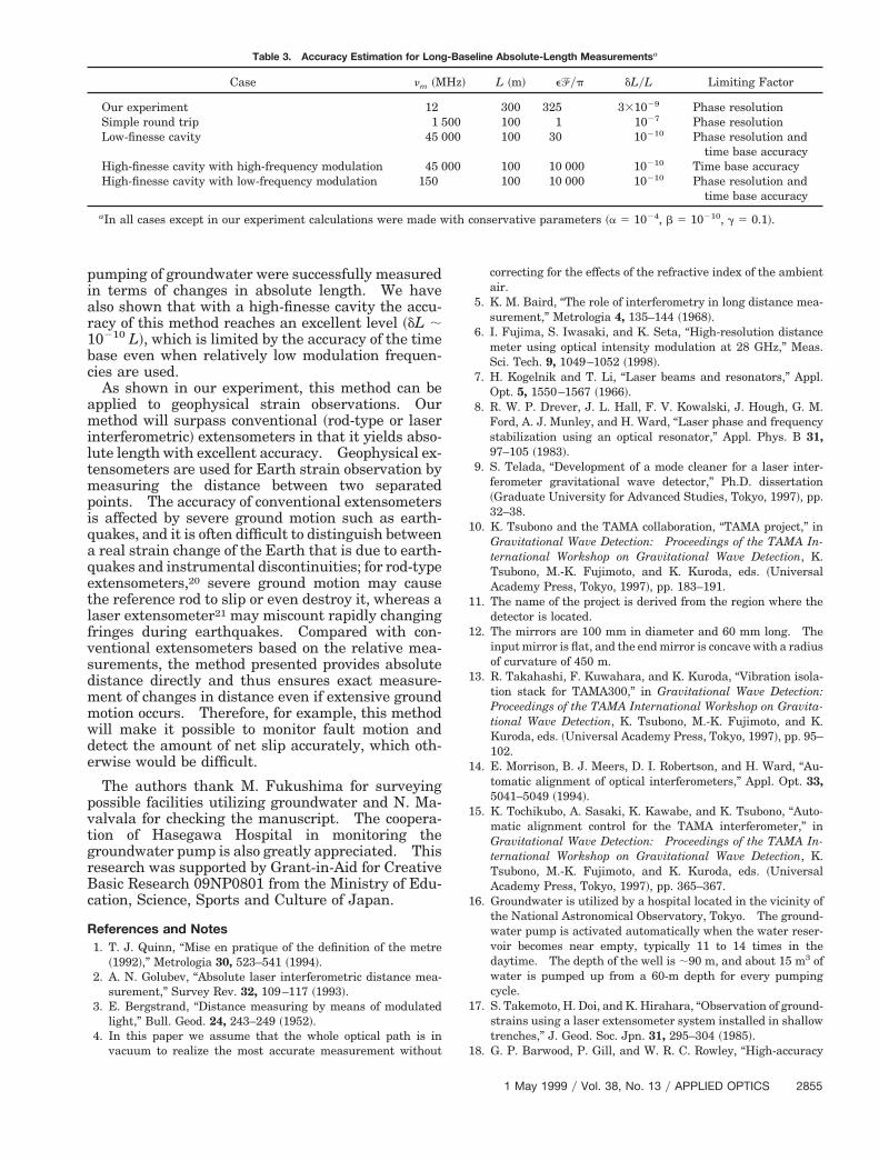
Nevertheless, according to expression ~23!, if we usea high-finesse cavity with e^yp 5 1 3 104 ~Ref. 19! toimprove the phase resolution, the time-base-limitedaccuracy can be attained with a relatively low mod-ulation frequency ~e.g., nm1 5 150 MHz for L 5 100m!; in comparison with that for a simple round-tripoptical path, a Fabry–Perot cavity improves lengthaccuracy by 103 with an order-of-magnitude lowermodulation frequency. Accuracy for the abovecases, including our experiment, is summarized inTable 3.
6. Conclusions
We have described a method for measuring absolutelength by use of an optical Fabry–Perot cavity incombination with phase-modulated light. An exper-imental demonstration with a 300-m Fabry–Perotcavity showed that a resolution of ;1 mm wasachieved in spite of a relatively low modulation fre-quency ~nm 5 12 MHz or lm 5 25 m! owing to thephase-sensitive characteristics of the Fabry–Perotcavity. In observation over a period of several days,Earth strain changes of 6 3 1028 that resulted from
1
Table 3. Accuracy Estimation for Long-Baseline Absolute-Length Measurementsa
pumping of groundwater were successfully measuredin terms of changes in absolute length. We havealso shown that with a high-finesse cavity the accu-racy of this method reaches an excellent level ~dL ;0210 L!, which is limited by the accuracy of the time
base even when relatively low modulation frequen-cies are used.
As shown in our experiment, this method can beapplied to geophysical strain observations. Ourmethod will surpass conventional ~rod-type or laserinterferometric! extensometers in that it yields abso-lute length with excellent accuracy. Geophysical ex-tensometers are used for Earth strain observation bymeasuring the distance between two separatedpoints. The accuracy of conventional extensometersis affected by severe ground motion such as earth-quakes, and it is often difficult to distinguish betweena real strain change of the Earth that is due to earth-quakes and instrumental discontinuities; for rod-typeextensometers,20 severe ground motion may causethe reference rod to slip or even destroy it, whereas alaser extensometer21 may miscount rapidly changingfringes during earthquakes. Compared with con-ventional extensometers based on the relative mea-surements, the method presented provides absolutedistance directly and thus ensures exact measure-ment of changes in distance even if extensive groundmotion occurs. Therefore, for example, this methodwill make it possible to monitor fault motion anddetect the amount of net slip accurately, which oth-erwise would be difficult.
The authors thank M. Fukushima for surveyingpossible facilities utilizing groundwater and N. Ma-valvala for checking the manuscript. The coopera-tion of Hasegawa Hospital in monitoring thegroundwater pump is also greatly appreciated. Thisresearch was supported by Grant-in-Aid for CreativeBasic Research 09NP0801 from the Ministry of Edu-cation, Science, Sports and Culture of Japan.
References and Notes1. T. J. Quinn, “Mise en pratique of the definition of the metre
~1992!,” Metrologia 30, 523–541 ~1994!.2. A. N. Golubev, “Absolute laser interferometric distance mea-
surement,” Survey Rev. 32, 109–117 ~1993!.3. E. Bergstrand, “Distance measuring by means of modulated
light,” Bull. Geod. 24, 243–249 ~1952!.4. In this paper we assume that the whole optical path is in
vacuum to realize the most accurate measurement without
Case nm ~M
Our experiment 12Simple round trip 1 5Low-finesse cavity 45 0
High-finesse cavity with high-frequency modulation 45 0High-finesse cavity with low-frequency modulation 150
aIn all cases except in our experiment calculations were made w
correcting for the effects of the refractive index of the ambientair.
5. K. M. Baird, “The role of interferometry in long distance mea-surement,” Metrologia 4, 135–144 ~1968!.
6. I. Fujima, S. Iwasaki, and K. Seta, “High-resolution distancemeter using optical intensity modulation at 28 GHz,” Meas.Sci. Tech. 9, 1049–1052 ~1998!.
7. H. Kogelnik and T. Li, “Laser beams and resonators,” Appl.Opt. 5, 1550–1567 ~1966!.
8. R. W. P. Drever, J. L. Hall, F. V. Kowalski, J. Hough, G. M.Ford, A. J. Munley, and H. Ward, “Laser phase and frequencystabilization using an optical resonator,” Appl. Phys. B 31,97–105 ~1983!.
9. S. Telada, “Development of a mode cleaner for a laser inter-ferometer gravitational wave detector,” Ph.D. dissertation~Graduate University for Advanced Studies, Tokyo, 1997!, pp.32–38.
10. K. Tsubono and the TAMA collaboration, “TAMA project,” inGravitational Wave Detection: Proceedings of the TAMA In-ternational Workshop on Gravitational Wave Detection, K.Tsubono, M.-K. Fujimoto, and K. Kuroda, eds. ~UniversalAcademy Press, Tokyo, 1997!, pp. 183–191.
11. The name of the project is derived from the region where thedetector is located.
12. The mirrors are 100 mm in diameter and 60 mm long. Theinput mirror is flat, and the end mirror is concave with a radiusof curvature of 450 m.
13. R. Takahashi, F. Kuwahara, and K. Kuroda, “Vibration isola-tion stack for TAMA300,” in Gravitational Wave Detection:Proceedings of the TAMA International Workshop on Gravita-tional Wave Detection, K. Tsubono, M.-K. Fujimoto, and K.Kuroda, eds. ~Universal Academy Press, Tokyo, 1997!, pp. 95–102.
14. E. Morrison, B. J. Meers, D. I. Robertson, and H. Ward, “Au-tomatic alignment of optical interferometers,” Appl. Opt. 33,5041–5049 ~1994!.
15. K. Tochikubo, A. Sasaki, K. Kawabe, and K. Tsubono, “Auto-matic alignment control for the TAMA interferometer,” inGravitational Wave Detection: Proceedings of the TAMA In-ternational Workshop on Gravitational Wave Detection, K.Tsubono, M.-K. Fujimoto, and K. Kuroda, eds. ~UniversalAcademy Press, Tokyo, 1997!, pp. 365–367.
16. Groundwater is utilized by a hospital located in the vicinity ofthe National Astronomical Observatory, Tokyo. The ground-water pump is activated automatically when the water reser-voir becomes near empty, typically 11 to 14 times in thedaytime. The depth of the well is ;90 m, and about 15 m3 ofwater is pumped up from a 60-m depth for every pumpingcycle.
17. S. Takemoto, H. Doi, and K. Hirahara, “Observation of ground-strains using a laser extensometer system installed in shallowtrenches,” J. Geod. Soc. Jpn. 31, 295–304 ~1985!.
18. G. P. Barwood, P. Gill, and W. R. C. Rowley, “High-accuracy
L ~m! e^yp dLyL Limiting Factor
300 325 331029 Phase resolution100 1 1027 Phase resolution100 30 10210 Phase resolution and
time base accuracy100 10 000 10210 Time base accuracy100 10 000 10210 Phase resolution and
time base accuracy
onservative parameters ~a 5 1024, b 5 10210, g 5 0.1!.
Hz!
0000
00
ith c
1 May 1999 y Vol. 38, No. 13 y APPLIED OPTICS 2855
length metrology using multiple-stage swept-frequency inter- factors of mirrors for a gravitational wave antenna,” Appl. Opt.
2
ferometry with laser diodes,” Meas. Sci. Technol. 9, 1036–1041~1998!.
19. S. Sato, S. Miyoki, M. Ohashi, M.-K. Fujimoto, T. Yamazaki,M. Fukushima, A. Ueda, K. Ueda, K. Watanabe, K. Naka-mura, K. Etoh, N. Kitajima, K. Ito, and I. Kataoka, “Loss
856 APPLIED OPTICS y Vol. 38, No. 13 y 1 May 1999
38, 2880–2885 ~1999!.20. H. Benioff, “A linear strain seismograph,” Bull. Seismol. Soc.
Am. 25, 283–309 ~1935!.21. V. Vali and R. C. Bostrom, “One thousand meter laser inter-
ferometer,” Rev. Sci. Instrum. 39, 1304–1306 ~1968!.