Embed Size (px)
Citation preview
ABSTRACT
Gordon Bell, William Il. Strecker November 8, 1975
COMPUTER STRUCTURES: WHAT HAVE WE LEARNED FROM THE PDP-ll?
Over the FDP-11’S six year life about 20,000 specimens have been built based on 10 species (models). Al though range was a design goal, it was unquantified; the actual range has exceeded expectations (5OO:l in memory size and system price]. The range has stressed the baa ic mini (mall computer architecture along all dimensions. The marn PM.5 structure, i.e. the UNIBUS, has been adopted as a de facto standard of interconnection for many micro and minicomputer systems. The architectural experience gained in the design and use of the PDP-11 will be described in terms Of its environment (initial goals and constraints, technology, and the organizationthat designs, builds and distributes the machine).
1.0 TNTRODUCTTON
Although one might think that computer architecture is the sole determinant of a machine, it is merely the focal point for a specification. A computer is a product Of its total environment. Thus to fully understand the POP-11, it is necessary to understand its environment.
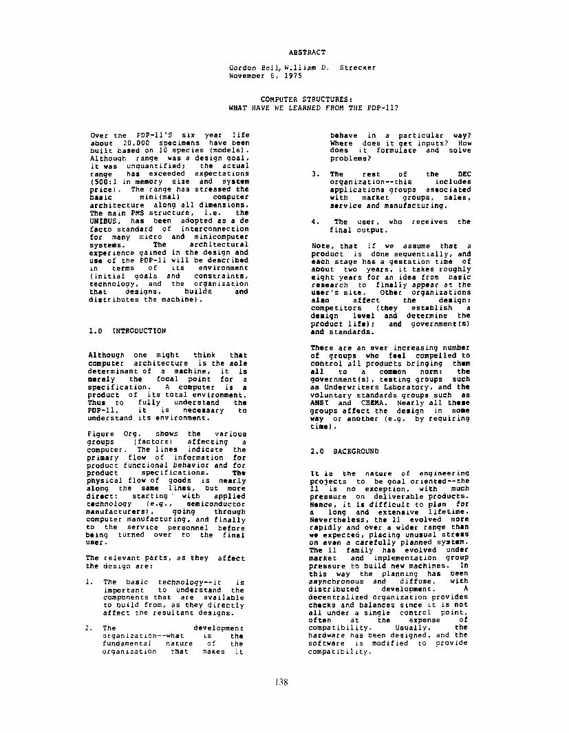
Figure Org. shows the various groups (factors) affectrng a COmQU te r . The lines indicate the primary flow of information for product functional behavior and for QrOdUC t specifications. The physical flow of goods is nearly along the same 1 ines, but more direct: starting with aQQ1 ied technology (e.g., semiconductor manufacturers), going throughcomputer manufacturing, and finally to the service personnel before being turned over to the Einal user.
The relevant parts, as they affect the desrgn are:
1. The basic technology--it is important to understand the components that are available to build from, as they directly affect the resultant designs.
2. The developmentorganrzatron--what is the fundamentai nature of the organrzatron that makes it
behave in a particular way? Where does it get inputs? HOW does it formulate and solve problems?
3. The rest of the DEC organization--this includes applications groups assoc ia ted with market groups # sales, service and manufacturing.
4. The user, who receives the final OUtQUt.
Note, that if we assume that a QrOduc t is done sequentially, and each stage has a gestation time of about two years, it takes roughly eight years for an idea from basic research to finally appear at the user’s site. Other organizations ala0 affect the design : competitors (they establish a deaign level and determine the product life): and government IsI and standards.
There are an ever increasing number of groups who feel compel led to control all products bringing them all common norm : the government (“5) , testing groups such as Underwriters Laboratory, and the voluntary standards groups such as ANSI and CBEWA. Nearly all these groups affect the design in some way or another (e.g. by reguir ingtime).
2.0 BACKGROUND
It is the nature of engineer ing projects to be goal oriented--the 11 is no exception, with much pressure on deliverable products. Hence, it is difficult to plan for a long and extensive lifetime. Nevertheless, the 11 evolved more
rapidly and over a wider range than we expected, placing unusual stress on even a carefully planned System-
The 11 family has evolved under market and implementation group pressure to build new machines. In this way the plannrng has been asynchronous and diffuse, with distributed development . A decentralized organization provideschecks and balances since it is not all under a single control point,of ten at the expense of compatibility. Usually, the hardware has been designed, and the software 1.5 modified to provide compatibility.
138

Indepenaen t of the plannrnq, the made to increase its address space. machrne has been very successful in In retrospect, rt IS clear that the marketplace, and wrth the since memory pr Ices decline at 26% sys terns prbgrams written for it. to 413 per year, and many users In the DaDer (Bell et al, 1970) we tend to buy constant dollar are f irs’t concerned with market systems, then every two or three acceptance and use. Features year 5 another bit is requrred for carried to other designs are also a the physical address space. measure of how it contributes to computer structures and are of Weakness 2 of not enough registers secondary importance. - was solved by providing eight
16-bit registers: subsequently six The PDP-11 has been successful in more 32-bit registers were added the marketplace with over 20,000 for floating point arithmetrc. The computers in use (1970-1975). It number of registers has proven
unclear how rigid a test (aside adequate . More registers would i:orn the marketplace) we have given just increase the context switching the design since a large and time, and also perhaps the aggressive marketing and sales programming time by posrng the organization, coupled with sof twace allocation dilemma for a compiler to cover architectural or a programmer. inconsistencies and omissions, can save almost any design. There was Lack of stacks (weakness 3) has difficulty in teaching the machine been solved, uniquely, with the to new users: this required a auto-increment/auto-decrement large sales effort. On the other addressing mechanism . Stacks are hand, various machine and operating used extensively in some languages, systems capabilities still are to and generally by most programs. be used.
Weakness 4, limited interrupts and slow con tex t switching has been generally solved by the 11 UNTEIJS vectors which direct interrupts
2.1 GOALS AND CONSTRAlNTS - 1970 when a request occurs from a given I/O device.
The paper (6ell et al, 1970) Byte hand1 ing (weakness 5) was described the design, beg inning provided by direct byte addressing.with weaknesses of minicomputers to remedy other goals and constraints. iiead-only memory (weakness 6) can These will be described tr iefly in be used directly without specialthis section, to provide a programming since all proceduresframework, but most discussion of tend to be pure (and reentrant) and the individual aspects of the can be programmed to be recursive machine will be described later. (or multiply reentrant). Read-only
memories are used extensively for Weakness 1, that of limited address bootstrap loaders, debuggingcapability, was solved for its programs, and now provide normal rmmediate future, but not with the console functions (in program)finesse it might have been. using a standard terminal, Indeed, this has been a costlyoversight in redundant development Very elementary I/O processingand sales. (weakness 7) is partially provided
by a better interrupt structure,There is only one mistake that can but so far, I/O processors per se be made in a computer design that have not been implemented. is difficult to recover from--not providing enough add:zis bits for Weakness 8 suggested that we must memory addressing memory have a family. Users would like to management _ The PDP-11 followed move about over a rangyof models. the unbroken tradition of nearly every known computer. Of course, High programming costs (Leakness 9) there is a fundamental rule of should be addressed because users computer (and per haps other ) program in machine language. Here designs which helps to alleviate we have no data to suggest this problem: any well-designed improvement. A reasonable
machine can be evolved through at comparison would be programmingleast one major change. It is costs on an 11 versus other extremely embarrassing that the 11 machines. We built more complex had to be evolved with memory systems (e.g., operating sys terns, management only two years after the computers) with the 11 than with paper was written outlining the simpler structures (e.g. PDP-8 or goal of providing increased address 15). Also, some systems space. All predecessor DEC designs programmrng is done usrnq higher have suffered the same problem, and level languages. only the PDP-10 evolved over a ten year period before a change was
139

Another constcalnt was the word lenq th had to be in multiples of eight bits. While this has been expensive within DEC because of our lnvestmenc in 12, 18 and 36 bit sys terns, the net effect has probably been war thwhile . The notron of word length is quite meaninqless in machines like the 11 and the IBM 360 because data-types are of varying lengths, and instructions tend to be in multiples of 16 bits. However, the addressing of memory for floatingpoint is inconsistent.
Structural flexibility (modularity1 was an impor tan t goal. This succeeded beyond expectations, and is discussed extensively in the part on PMS, in par titular the UNIBIJS section.
There was not an explicit goal of microprogrammed implementation.Since large read-only memories were not available at the time of the Model 20 implementation,microprogramming was not used. Unfortunately, all subseouen t machines have been microproqrammed but with some additional difficultyand expense because the initial design had poorly allocated opcodes, but more impor tan t the condition codes behavior was over spacified.
Understandability was also stated to be a goal, that seems to have been missed. The initial handbook was terse and as such the machine was only saleable to those who really understood computers. It is not clear what the distribution of first users was, but probably all had previous computing experience . A large number of machines were sold to extremely knowledgeable users the universities and laborato:?es. The second handbook cdme out in 1972 and helped the learning problem somewhat, but it is still not clear whether a user with no previous computerexperience can determine how to use a machine from the information in the handbooks. Fortunately, two
comw.8 ter science tax tbooks (E&house, 75; and Stone and Siewiorek, 75) have been written baaed on the 11 to assist in the learning problem.
2.2 FEATURES THAT HAVE MIGRATED TO OTHER COMPUTERS AND OFFSPRINGS
A suggested test (Hell et al 1970) was the features that have migrated into competitive designs. We. have not fully permitted this test because some basic features are patented: hence, non-DEC desrgners are reluctant t0 use VariOUS 1dedS.
140
At least two organizations have mdde machines with similar bus and ISP structures (use of address
modes, behavror of registers as program counter and stack); and a third organization hdS offered a plug-replacement system for sale.
The UNIBUS structure has been accepted by many designers as the PMS structure. This interconnect ion scheme is especially used in microprocessordesigns. Also, as part of the UNIBUS design, the notion of mwerng I/O data and/or control registers into the memory address space has been used often in the microprocessor designs since it eliminates instructions in the ISP and requires no extra control to the I/O section.
Finally, we were concerned in 1970 that there would be offsprings--cledrly no problem:there have been about ten implementations. In fact, the family is large enough to suggest need of family planning.
3.0 TECHNOLOGY
The computers we build are strongly influenced by the basic electronic technology. In the case of computers , electronic information processing technology evolution has been used to mark the four generations.
3.1 Effects Of .%&conductor Memory On The PDP-11 Model De8igns
The PDP-11 computer set ies design beqdn in 1969 with the Model 20. Subsequently, 3 models were introduced as minimum cost, best cost/performance, and maw imum performance machines. The memory technology in 1969 formed several constraints:
1. Core memory for the primary (program) memory with an
eventual trend toward semiconductor memory.
2. A comparatively smdll number of high speed registers for processor state (i.e. general registers), with a trend toward larger, higher speed register files at lower cost. Note, only 16 word read-write memories were avdilableat design time.
3. Unavailability of large, h iqh speed read-only memories,
permitting a microprogrammed approach to the design of the control part. Note, not for ca paper, read-only memory was unavailable al though slow, read-only MOS was available for character generators.
These constraint5 established the following desrgn principles and attitudes:
1. It should be asynchronous and capable of accepting various conf iqurations of memories in sire and speed.
2. It should be expandable, to take advantage of an eventually laraer number of resisters for more data-types and improve context switching time. Also, more registers would Fermi t eventually mapping memory to provide a virtual machine and protected multiprogramming.
3. It could be relatively complex, so that an eventual microcode approach could be used to advantage . New data-types could be added to the rnstruction set to increase performance even though theyadded complexity.
4. The UNIBUS width would be relatively wide, to get as much performance as possible, since LSI was not yet available to encode functions.
3.2 Variations In PDP-11 Models Through Technology
Semiconductor memory (read-only and resd-wr i te) were used to tradeoff coat performance across a reasonably wide range of models. Various techniques baaed on semiconductors are used in the tradeoff to provide the range . These include:
1. Improve performance through brute force with faster memories. The 11/45 and 11/70 uses bipolar and fast MOS memory.
2. Microprogramming (see below) to improve performance through a more complex ISP (i.e.,floating point).
3. Mu1 tiple copies of processor state (context) to improve time to switch context among various runnlnq programs.
4. Additional registers for additional data-types--i.e.,floatrnq point arithmetic.
5. Improve lsolatlng program
the
from
reliabilrty(protectrngj
another.
by one
6. Improve multiplephysical programProviding requiresin the (i.e.
memory
performance by mapping programs Into the same
memory, giving each a virtual machine. the last two points
;I signif icant increase number of reqlsters
at least 64 word fast arrays).
4.0 THE ORGANIZATION OF PEOPLE
Three types of design are based both on the technology and the cost and performance considerations. The nature of this tradeoff is shown in Figure DS. Note, that one starts at 0 cost and performance,proceeds to add cost, to achieve a base Iminimum level of functionality). At this point,certain minimum goals are met: for the computer, it is simply that there is program counter, and the simplest arithmetic operations can be carried out. It is easy to show (baaed on t:iwTurinq machine) that only a Instructions are required, and from these, any program can be written. From this minimal point, performanceincreases very rapidly in a stepfashion (to be described later I for quite sometime (due to fixed overhead of memories, cabinets, powar, etc.) to a point of inflection where the cost-effective solution is found. At this point,performance continues to increase until another point where the performance is maxim ixed . Increas rng the size imp1 ies physical constraints are exceeded, and the machine becomes unbuildable, and the performance can go to 0. There is a generaltendency of all designers to “n+l” (i.e., incrementally add to the
design forever) . No design is so complete , that a redesign can’ t improve it.
The two usual problems of design are : inexperience and “second-systemitis”. The first problem is simply a resources problem. Are there peopleavailable? What are their backgrounds? Can a small grow work effectively on architectural definitions? Perhaps most important is the principle, that no matter who is the architect, the design must be clearly understood by at least one person.
Second-systemitis is the phenomenon Of def ininq a system on the basis of past sya tern history.
141
Invar Iably, the system solves all past problems.. . border ing on the unbulldable.
4.1 PDP-11 Exper xnce
Some of the PDP-11 architecture was initially carr red out by at Carnegie-Mellon University (HM with CBI . Two of the useful ideas: the UNIBUS, and the use of generalregisters in a substantrally more general fashion (e.g. as stack pointers) came out of earlier work (CB) at CMU and was described in COMPUTER STRUCTURES (Bell and Newell, 1971). During the detailed design amelioration, 2 persons (HM, and RC) were responsible for the specification.
Although the architectural activity Of the II/20 proceeded In parallelwith the implementation, there was less interaction than in previous DEC designs where the first implementation and architecture were carried out by the same person. As a result, a slightpenalty was paid to build subsequent designs, especially vis a vi5 microprogramming.
As the various models began to be built outside the originalPOP-11/20 group, nearly all architectural control (XC)disappeared, and the architecture was managed by more people, and de5ign resided with no one person! A similar loss of control occurred in the design of the per iphecalsafter the basic design.
The first designs for 16-bit computers came from a group placed under the PDP-15 management marketing person, with engineeri:;background). It was called PDP-X, and did include a range. As a range architecture, it was better thought out than the later PDP-11, but didn’t have the innovative aspects. Unfortunately, this group was intimidating, and some members lacked credibility. The group also managed to convince management that the machine was potent ially as complex as the PDP-10 (which it wasn’t) ; since no one wan ted another large computer disconnected from the main business, it was a sure suicide. The (marketing) management had little understandingof the machine. Since the peopleinvolved in the design were apparently simultaneously descgnrngData General, the PDP-X was not of foremost rmpor tance.
As the FDP-X pro]ect folded and the GCM (for @esk Calculator Machine
for securrty) project started up,design and planning were disarray, since Data General hi: been formed and was competing with the PDP-8 usrng a very small 16-bit computer . Al though the Product Line Manager, d former engineer(NM) for the PDP-8, had the responsibility this time, the new project manager was mathematrcian/programmer followeda by another manager (RC) who had managed the PDP-8. Work proceeded for several months based on the DCM and with a design review at Carnegie-Mellon University in late 1969. The DCM review took only a few minutes. Aside from a generaldullness and a feeling that it was too little too late to compete. It was difficult to program(especially by compilers).However, it’s benchmark results were good. (We believe it had been tuned to the benchmarks, hence couldn’ t do other problems verywell.) One of the designers (HM)brought along the kernel of an alternative, which turned out to be the PDP-11. We worked on the design all weekend, recommending a switch to the basic 11 design.
At this point, there were reviews to ameliorate the design, and each suggestion, in effect, amounted to an n+l ; the implementation was proceeding in parallel (JOI and since the logic design was conventional , it was difficult to tradeoff extensions. Also, the design was constrained with boards and ideas held over from the DCM. (The only safe way to design a range is simultaneously do both high and low end designs.) During the summer at DEC, we tried to free oP code space, and increased (nil’edl the UNIBUS bandwidth (with an extra set of address lines), and outlined alternative models.
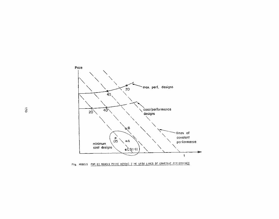
The advent of large, read-onlymemories, made possible the various follow-on designs to the ll/ZO.Figure “Models’ sketches the cost of various models versus time, with lines of cons is tent oerformance. This very clearly shows&the design 5 tyles (ideologies) . The 11/40 design was started right after the 11/20, al though it was the last to come on the market (the low and high ends had higher priority to get into product ion as they extended the market). Both the 11/04 and 11/45 design groups went through extensrve buy in processes, as they came into the 11 by first proposrng alternative designs. In the case of the 11/45, a larger, 11-like 18-bit machine was proposedby the 15 group: and later, the LINC engineerrng group proposed an alternative design which was subset compa table at the symbolic program level. As the groups constdered
142
the software ramificatrons, buy-in was rap&d. Frgure Models shows the mrnrmum cost-orrented group has two successors providing lower cost (yet higher performance) and the same cost wrth the ability to have laroer memories and perform better. Note, both of these- came from a backup strategy to the LSI-11. These-come from larger read-only memor ies, and increased understanding of how to implement the 11.
The 11/7O is, of course, a natural follow on to extend the performanceof the 11/45.
5.0 PMS STRUCTURE
In this section, we give an overview of the evolution of the PDP-I1 in terms of its PMS structure, and compare it with expectatrons (Bell et al. 1970). The aspects include : the UNIBUS structure; UNIBUS performance: use for diagnostics: architectural control required: and multi-computer and multi-processor computer structures.
5.1 The UNIBUS - The Center Of The Pm structure
In general, the UNIBUS has behaved beyond expectations, acting as a standard for intercommunication of peripherals. Several hundred types of memor les and peripherals have been attached to it. It has been the principle PMS interconnect ion media of MD-PC and oeriuherals for systems in the range- 3K dollars to 1OOK dollars (1975). For larger sys terns supplementary buees for PC-Mp and HP-MS traffic have been added. For very small sys terns, like the LST-11, a narrower bus ((j-bus) has been designed.
The UNIBIJS by being a standard ha8 provided us with a PMS architecture for easily configuring systems; any other organization can also build components which interface the bus... clearly ideal for buyers.Good bU88eS Istandards) make goodneighbors ( in terms of engineering), since people can concentrate delrign in a structured fasE:on. Indeed, the UNIBUS has created a completesecondary industry dealing in alternatrve sources of supply for memorres and peripherals. Outside of the IBM 360 r/oHultiplexor/Selector bus, the UNIBUS 1s the most widely used
computer rnterconnectron standard. Al though it has been difficult to fully specrfy the UNIBUS such that one can be certain that a grven system will work electrically and without missed data, specificationis the key to the UNTBUS. The bus behavior specification is a yetunsolved problem in dealing with complex1 ty--the best descriptions are based on behavror (i.e., timingdiagrams).
There are also problems with the deEi9n of the UNIBUS. Al though parity was assigned as two of the bits on the bus (parity and parityis available), it has not been widely used. Memory parity was implemented directly in the memory, since checking required additional time. Memory and UNIBUS parity is a good example of nature of engineering optimization. The tradeoff is one of cost and decreased performance versus decreased service cost and more data integrity for the user: The engineer is usually measured on production cost goals, thus paritytransmission and checking are clearly a capability to be omitted from design . ..especially in view of loet performance. The internal Field Service organization has been unable to guantify the increase in service cost savings due to shorter MTTR by better fault isolation. Similarly, many of the transient errors which parity detects can be detected and corrected by software device driver8 and backupprocedures without parity. With lower cost for logic and increased r88pOnEibility (scope) to include warranty C08tS a8 part of the product deeign cO8t forces much more checking into the design.
The interlocked nature of the transfers AS such that there is a deadlock when two compu thr s are joined together using the UNIBUS window. With the window a computer can map another computer’s address space into its own address space in a true mu1 tiprocessor fashion. De8dlock occurs when the two computers simultaneously attempt to accees the other’s addresses through each window. A request to the window is in progress on one UNIBUS , and at the same time a request to the other UNfBUS is in progress on the requestee’s UNIBUS, hence neither request can be answered, causing a deadlock. Cne or both requests are aborted and the deadlock is broken by havingthe UNIBUS time out since this is eguivalen t to a non-existent address (e.g., a memory). In this way the sys tern recovers and requests can be reissued (which may cause deadlock) . The UNIBUS window is conf rned to appi ica trons where there likely to be a lowdeadlock’sate.
143
5.2 UNIBUS and Performance 5.3 Evolution Of Models: Predicted Optimality Versus Actual
Al though we always want more performance on one hand, there is an equal pressure to have lower cost. Since cost and peformance are almost totally correlated the two goals perfectly conflict. The UNIBUS has turned out to be optimum over wide dynamic range of product:, (argued below) . However,
the lowest site system, the trbus has been introduced, which contains about l/2 the number of conductors: and at the largest systems, the data path width for the processor and memory has been increased to 32-bits for added performance although the UNIBUS is still used for communication with most I/O controllers.
Since all interconnection schemes are highly constrained, it is clear that future lower and higher systems cannot be accomplished from a single design unless a very low cost, high performance communication media (e.g. optical)is found.
The optimaiity of the UNIBUS comes about because memory size (numberof address bits) and I/O traffic are correlated with the processor speed. Amdahl’s rule-of-thumb for IBM computers (including the 360)
one byte of memory is required E instruction/set and one bit of I/O is required for each instruction executed. For our applications, we believe there is more computation required for each memory word, because of the bias toward control and scientific applications. Also, there has been less use of complex instructions typical of the IBM computers. Hence, we assume one byte of memoryis required for each two instructions executed, and assume one byte of I/O is an upper bound (for real time applications) for each instruction executed. In the FDP-11, an average instruction accesses three to five bytes of memory, and with one byte of io, up to six bytes of memory are accessed for each instruction/set. Therefore, a bus which can support two megabytejsec traffic permitsinstruction execution rates of .33 to 1 5 mega instruction/set. This imputes to meory sizes of .16 to .2s megabytes: the maximum allowable memory is .3 to ,256 megabytes. 6y using a cache memorywith a processor, the effective memory processor rate can be increased to further balance the processor. Alternatively, faster floating point operations will or inq the balance to be more like the IBM data, requiring more memory.
144
The or iq inal prediction (Bell et al, 1970) was that models with increased performance would evolve using: increased path width for data: multi-processors: and wpar a ted bus structures for control and data transfers to secondary and tertiary memory.Nearly all of these forms have been used, though not exactly as predicted. (Again. this points to lack of overall architectural planning versus our willingness and belief that the suggest ions and plans for the evolution must come from the implementation groups.1
In the earlier 11/45, a separatebus was added for direct access of either bipolar (300ns) or fast MOS (400ns) memory. In general, it was assumed that these memories would be small, and the user would move the important part of his algorithm to the fast memory for direct execution. The 11/45 provided second LJNIHUS for direct transmission of information to the fart memory without PC interference. The rr/rs also increased performance by adding a second autonomous data operationunit called the Floating Point Processor (actually not processor) . In this way, boti integer and floating pointcomputation could proceedconcurrently.
The 11/70, a cache based processor. is a logical extension of usingfast, local memories, but without need for expert movement of data. It has a memory path width of 32-bits, and the control portion and data portion of I/O transfers have been separated as originallysuggested. The performancelimitation of the UNIEIIJS are removed, since the second Mp systempermits data transfers of up to five megabytes/set (2.5 times that of the UNIBUS) . Note, that a peripheral memory map control is needed since Mp address space (twomeaabvtes) exceeds the UNIBUS. In this - way, direct memory access devices on the UNIEUS transfer data into a mapped portion of the largeraddress space.
5.4 Multi-processor ComputerStructures
Although it is not surprising that multi-processors have not been used except on a highly specialized basis, it is depressing. In Computer Structures (Bell and Newell, 711 we carried out 3n
3

analysis of the IBM 360, predicating a multi-processor aeslgn. The range of performance covered by the PDP-11 models is substantially worse than with the 360, al though the compe t I t Lve environment of the two companies is substantially different. For the 360, smaller models appear to perform worse than the technologywould predict. The reasons whymu1 t iprocessors have not materialized may be:
1. The basic nature of engineeringis to be conservative. this is a classical deadlock situation: we cannot learn how to program multiprocessors until such systems exist: a system canot be built before programs are ready.
i The market doesn ’ t demand them. Ano the r deadlock : how can the market demand them, since the market doesn ’ t even know that such a structure could exist? IBM has not yet blessed the concept.
3. We can always build a better single, special processor. This design philosophy stems from local optimization of the designed object, and ignoresglobal costs of spares, training, reliability and the ability of the user to dynamically adjust a configuration to his load.
4. There are more available designs for new processors than we can build already..
5. Planning and technology are asynchronous. Within DEC, not all products are planned and built at a particular time, hence, it is difficult to getthe one right time when a multiprocessor would be better than an existing Uniprocessortogether with one or two additional new processors.
6. Incremental market demands require specific new machines. By having more products, a company can better track compe t i tor s by specific unipracessors.
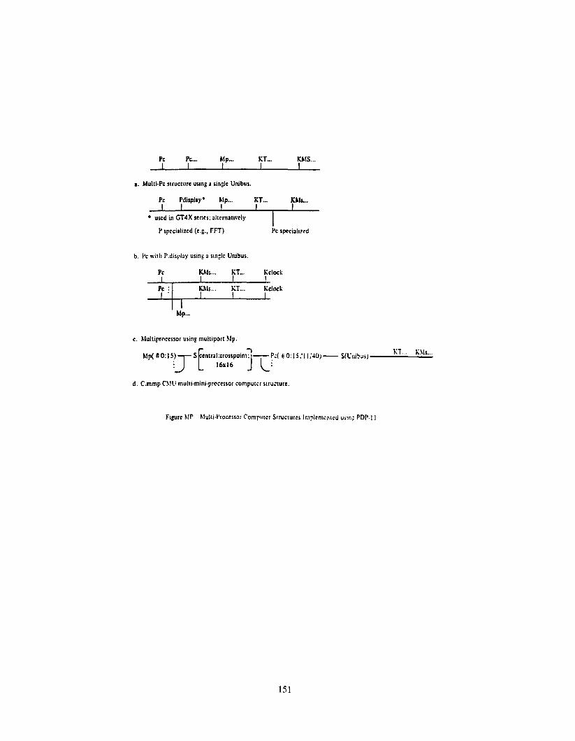
5.4.1 Existent Multiprocessors -
Figure MP gives some of the mu1 t lprocessor sys terns that have been built on the 11 base. The topmost structure has been built using11/05 processors, but because of improper arbitration in the processor, the performance expectedbased on memory contention didn’t materialize. We would expect the
following results for multiple11/05 processors sharing a srngle UNIBUS:
PC. PC. PRICE/ SYS Price/
IPC HP PERF PRICE PEW* er1ce PfQP* 1 .6 1 1 1 3 1 2 1.15 1.85 1.23 .66 3.23 .58 3 1.42 2.4 1.47 -61 3.47 .Q8 40 2.25 1.35 .6 3.35 .49
*PC cost only l * Total System,assumrnq l/3 of system is Pc.cost
From these results we would expectto use up to three processors, to give the performance of a model 40. More processors, while increasing the performance, are less cost-effective. This basic structure has been applied on a production basis in the GT4X series of graphics processors. In this scheme, a second P.display is added to the UNIBUS for display picturemaintenance.
The second type of structure g iven in Figure MP is a convent ional multiprocessor using multiple port memories. A number of these systems have been installed and operate guite effectively, however, they have only been used for specialized applications.
The most extensive mu1 tiprocessor structure, C.mmP, has been described elsewhere. Hopefully,convincing arguments will be forthcoming about the effectiveness of multiprocessors from this work in order to establish these structures on an applied basis.
6.0 THE TSP
Determining an ISP is a designproblem. The initial 11 design was based substantially on benchmarks , and as previously indicated this approach yielded a predecessor (notbuil tl that though performing best
the six benchmarks, was dOlfficu1 t to program for other applications.
6.1 General ISP Design Problems
The guiding principles for ISP design in general, have been especially difficult because:
1. The range of machines arguesfor different encoding over the range. At the smallest systems, a byte-or ien ted approach with small addresses
145
is optrmum, whereas largerLmplementatlons require more operations. larger addresses and encoding efficiency can be traded off to garn performance.
The 11 has turned out to be applied (and hopefullyeffective) over a range of 500 in sys tern price ($500 to
$250,000) and memory size (8kbytes to 4 megabytes). The 360 by comparison varied over a similar range: from 4k bytes to 4 megabytes.
2. At a given time, a certain style of math ine ISP is used because of the rapidly varyingtechnology. For example, three address machines were initially used to minimize processor state (at the expense of encoding efficiency), and stack machines have never been used extensively due to memory access time and control complexity. In fact, we can observe that machines have evolved over time to include virtually all importantoperations on useful data-types.
3. The machine use vat ies over time. In the case of DEC, the initial users were sophisticated and could utilize the power at the machine language level. The II provided more fully general registers and was unique in the minicomputer marketplace, which at the time consisted laroelyof 1 or 2 accumulator machines with 0 or 1 index registers. Also, the typical m in icompu ter operation codes were small. the 11 extended data-typing to the byte and to reals. by the extension of the auto-indexingmode, the string was conveniently programmed, and the same mechanism provided for stack data-structures.
4. The machine is applied into widely different markets. Initially the 11 was used at the machine language level. The user base broadened byapplications with substantiallyhigher level languages. These languages initially were the scientific based reoister transfer languages such BASIC, FORTRAN, CEC’S FOCAL: but the machine eventually began to be applied in the commercral marketplace fo.- the RPG , COBOL, DIBOL. and BASIC-PLUS languages which provided string and decimal data-types.
5. The crlterla for a capability In an lnstructlon set IS hlqhly
variable, and borders on the artistrc. Ideal goals ace thus to have a complete set of operations for a q iven basic data-type (e.g.integers) --completeness, and operations would be the same for varying lengthdata-types --orthogonality. Selection of the data-trues is totally a function oi‘ the application. That is, the 11 considers both bytes and full words to be - integers, yetdoesn ' t have a full set of operations for the byte; nor are the byte and word ops the same. BY adhering to this pc inc iple , the compiler and human code generators are greatly aided.
We would therefore ask that the machine appear elegant, where elegance is a combined qua1 i tyof instruction formats relating to mnemonic significance, operator/data-type completenessand orthogonality, and addressing consistency. BY having completely general facilities (e.g., registers) and which are not context dependent assists in minimizing the number of instruction types, and greatly aids in increasing the understandability (and u5efulness).
6. Techniques for generating code by the human and compiler vary widely. With the 11. more addressing modes are provided than any other computer. The a modes for source and destination with dyad ic operators provide what amounts to 64 possible instructions: and by associating the Program Counter and Stack Pointer registers with the modes, even more data accessing methods are provided. For example, 18 forms of the MOVE instruction can be seen (Bell et al, 1971) as the machine is used as a two-address, general registers and stack machine programforms. (The price for this generality is extra bits). In general, the machine has been used mostly as a general register machine.
7. Basic design can take the verygeneral form or be highly specific, and design decisions can be bound in some combination of microcode oc macrocode with no good criteria for tradeoff.
146
6.2 Problems In Extendlnq The Machine Range
Several problems have arisen as the basic machine has been extended:
1. The opera tron-code extension problem--the initial design did not leave enough free opcode space for extending the machine to increase the data-types.
At the t lme the 11/45 Was designed (FPP was added) , several extension schemes were examined : an escape mode to add the floating pointoperations: bringing the 11 back to a more convent ional general register machine by reducing the modes and finally, typing the data by adding a
global mode which could be switched to seiec t floating point ( Lns tead of byteoperations).
2. Extend ina the addressinq range-- the VNTBUS limits the physical memory to 262,144 bytes (la-bits). the implementation of the1nll/70, th; physical address was extended to 4 megabytes by providing a UNZBUS map so that devices in a 262K UNIBIJS spacecould transfer into the 4 megabyte space by mapping registers.
While the physical address limits are acceptable for both the UNIGUS and larger sys terns, the address for a single program is still confined to an instantaneous space of 16 bits, the user vlc tual address.
The main method of dealing with relatively small addresses is via process-oriented operating sys terns that handle large numbers of smaller tasks. This is a trend in operating systems, especially for processcontrol and transaction processing. It also enforces a structuring discipline in the (user) program organization. The RSX series operating systems are organized this way, and the need for largeaddresses except for problemswhere large arrays are accessed is minimized.
The initial memory management proposal to extend the virtual memory was predicated on dynamrc, rather than static assignment of memory segmentregisters. In the current memory management scheme, the address registers are usuallyconsidered to be static for a task (al though some operating
systems provide functions to get additional segments).
7.0 SUMMARY
This paper has re-examined the PDP-11 and compared it with the initial goals and constraints. With hindsight, we now clearly see what the problemswith the initial design were. Design faults occurred not through ignorance, but because the design was started too late. As we continue to evolve and improve the PDP-11 over the next five years, it Will indeed be interesting to observe, however, the ultimate test is use.
HTELIOGRAPHY
Ames, G.T., Drongowski, P.J. and Fuller, S.H. Emulating the Nova on the PDP-11/40: case study.Proc. COMPCON (19;5,.
Bell, G., Cady, R., McFarland, H., Delagi, E., O’Loughlin, J., Noonan, 6 . , and Wulf, w. A new architecture of minicomputers-- the DEC PDP-11. Proc. SJCC (1970)Vo136, ~~-657-675.
Bell, C.G. and Newell, A. Computer Structures. McGraw Hill (1971)
Bell, J.R. Threaded code. CONM ACM (June 1973) Vol 16, No. 6, PP370-372.
Eckhouse, R.H. MinicomputerSys terns : organization and programming (PDP-11).Prentice-Hall, (1975)
Fusfeld, A. R. The technological progress function. TechnologyReview (Feb. 1973) FP. 29-38
McWilliams, T., Sherwood, W.,Fuller, S., PDP-11 Implementationusing the Intel 3000 microprocessor chips. Submitted to NCC (May 1976)
O’Loughlin, J.F. Microprogramming a fixed architecture machine. Microprogramming and Sys terns Architecture Infotech State of the Art Report 23. ~~205-224
Ornstein, 1972? (page 28)
Stone, H.S. and Siewiorek, D.P. Introduction to computerorganization and data structures: PDP-11 Edition. McGraw-Hill, (19751
Turn, R. Computers in the 1980’s. Columbia University Press 1974.
Gulf, W.A., Bell, C.G., C.mmp: A multi-mini-processor. FJCC (1972)
147

BASIC REtC; ADVANCED
DEVELOPMENT
APPLIED TECHNOLOGY
(E.G. SEMI-COt0JCTCRS)
-
-
IMPLEMENTATION ---
I
APPLICATIONS (HARDWARE/ SOFTWARE)
MKT/SALES
4
-
II
USEH
ARCHITECTURE -
Competitors
Governments, standards,/ testing, professional societies
-- op. SYS.
LANGUAGES
e flow of information (specifications, ideas, etc.)
FlGURE.ORt. STRUCTURE OF ORGANIZATION AFFECTING A COMPUTER DESIGN
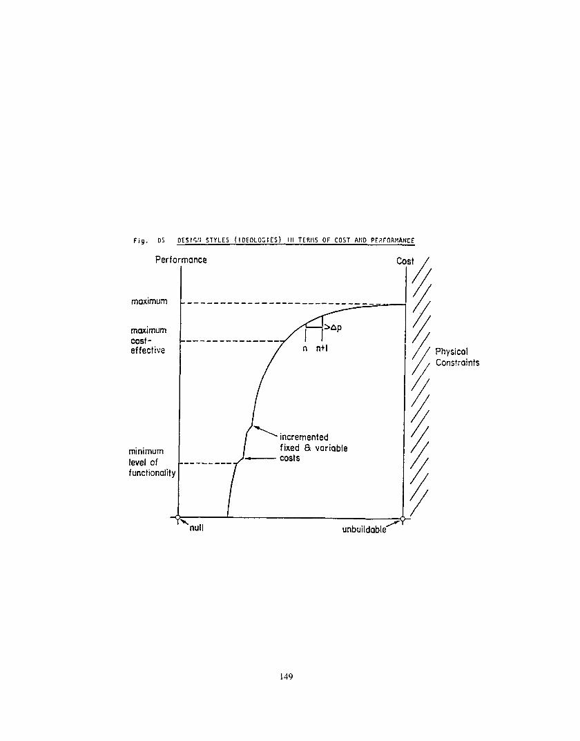
Fig. DS DESlcll STYLES (IDEOLOGIES) 111 TERIIS OF COST AND PERFORMANCE
Performance it
/
maximum /
/
maximum / cast-effective
/
/ Physical Cons?raints
/
/
/
/
1 incremented /
minimum level of functionalit)
.-------f -
fixed 8 costs
variable /
/
/
/
I /
unbuildable /
149
Price \\ \\
A--
Fig. HODELS PDP-I I MODELS PRICE vE9SIJ; T’rlE \llTtI LINES OF COttSTA;IT i’CEt0QtVA’CE
a.
PC PC... Mp... I I I
MUM-PC strucfure using a sir& Unibos.
PC Pdisplry l hip...
I I
l used in CT4X sericr; al~ernr~~wly
P spcciahrcd (e.g.. FIT)
ET... WK... I
KT... KMS... I
PC spcrirlvcd
c. hlultiprnccssor usq muttiporl Mp.
h1p(CO:lS) S encral:crosspom~:
3 E 3
-16x16
d. C.mmp Cblll rnulri-mini.pr@:cssor Compwcr
Pd ii 0: I5 ;‘I I ;4Oj C’
slru;wre.
- SICnibui) Ki... ys...
Figure bit’ hlul~i~l’roccssor Compu~cr S~rw~ures Im~tenren~crj uiln; PDP.t t
151