Embed Size (px)
Citation preview

Contents
Abstract.............................................................................................2
1.Introduction...................................................................................3
2.Background....................................................................................3
2.1.Project description....................................................................3
2.2.Case study................................................................................4
3.Project component......................................................................19
3.1.Microcontroller PIC16F877:.........................................19
3.2.Sensors and Detectors:................................................22
3.2.1.Smoke Detector........................................................22
3.2.2.Motion Detector :.....................................................24
3.2.3.Manual Call Point......................................................26
3.3.GSM Module.....................................................................26
3.4. FTP SERVER.....................................................................28
3.5.Camera...............................................................................28
4.1. Design procedure..................................................................28
4.1.1 Case One...........................................................................29
4.1.2. Case Tow..........................................................................29
6.1. Introduction to GSM system......................................30
6.2. Sensors.............................................................................31
6.3.FTP SERVER......................................................................38
6.4.Python language.............................................................39

Table of figures
Figure 1 block diagram for monitoring system using GSM network........4Figure 2 block diagram for monitoring system using GSM network........5Figure 3 Manual call points......................................................................7Figure 4 Manual call points......................................................................7Figure 5 Smoke detectors......................................................................10Figure 6 Smoke detectors......................................................................11Figure 7 top of detector.........................................................................11Figure 8 s sensors and manual call point...............................................13Figure 9 sort of sensors..........................................................................14Figure 10Pin diagram of PIC16F877.......................................................20Figure 11 interface RS232......................................................................21Figure 12Basic circuit Schematic............................................................21Figure 13 • ULN2003..............................................................................22Figure 14 Photoelectric smoke detector..................................................
23 Figure 15 Ionization smoke detector.......................................................
23Figure 16 Smoke detector.....................................................................23Figure 17 Motion Detectors...................................................................25Figure 18Motion Detectors....................................................................25Figure 19Manual Call Point....................................................................26Figure 20Telit GSM Module [3]..............................................................27Figure 21 Telit GSM Module board........................................................27Figure 22 Sensor coverage diagram.......................................................32Figure 23................................................................................................36Figure 24Flame detectors regions.........................................................38Figure 25 FTP Servers.............................................................................39

Abstract
In our project we want to design protection system from fire and theft and we want to monitor the building by using cameras , We will use some sensors to detect fire and theft ,and when detect the risk by sensors, will run the alarm and our microcontroller will receive the signal and collecting data from several sensor and then display the status of each sensors on a web-site and send a message to the owner and a warning to the police station.
It also shown how much progress had been done in this semester and what we are about to do next in order to make this project work.Appendix in the end of the report discusses the concepts of GSM, FTP server, and detectors .
1.Introduction
In this project we are going to build complete alarm system to get the status of (Hospital , building or anything that needs to protect from theft or fire )In addition we can use this project in many applications .When use this protection method In some cases there is a false alarmcaused by the accuracy of sensors or Installation these sensors or User Error,later we will explain how to reduce the false alarm error to improve the protection system.Our goal from this project is to reduce the time needed to identify and fixed the problem when accurse . for example, If the police had received a message telling about the occurrence of the risk, the police will make sure of a risk then will make the necessary protection .
2.BackgroundIn order to understand the concepts of our project we need to give a simple theoretical introduction about this project's existence, concept and applications in our world.
2.1.Project description
In general, the complete alarm system can be summarized by the following figure:
Figure 1 block diagram for monitoring system using GSM network
In our project we use a microcontroller interfaced with the sensors to be monitored through RS-232 or any protocol or technique in order to take the signal from the sensors to the microcontroller, then the microcontroller will make some process as flow chart . so we can monitor our system remotely. We can use a GSM module connected to the microcontroller in order to upload /download data to/ from an communication system. When the police receive the message will do some necessary procedures for the prevention of fire or theft.

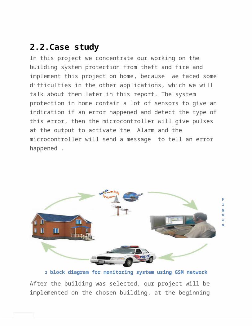
2.2.Case study In this project we concentrate our working on the building system protection from theft and fire and implement this project on home, because we faced some difficulties in the other applications, which we will talk about them later in this report. The system protection in home contain a lot of sensors to give an indication if an error happened and detect the type of this error, then the microcontroller will give pulses at the output to activate the Alarm and the microcontroller will send a message to tell an error happened .
Figure
block diagram for monitoring system using GSM network
After the building was selected, our project will be implemented on the chosen building, at the beginning will be studied each detectors and the characteristics of each one are used in our project and how they are installed and connected .
Our project have many sensor to detect the risk, some of these sensor we use to detect the fire and other use to detect the theft. We will start to explain how to choose and distribute these sensors in the building
Before a protection system can be designed, it is necessary to define the main objectives of the system. This is normally determined by risk assessment .
When we implement our project, we must determine the type of fire and theft protection system we use in the building .
To solve this problem we decide to use a camera to capture a photo for the seven segments of the elevator, and then by image processing we can determine the errors code.
After we search about this method, we found that it’s more efficient to use a mobile phone with built in camera instead of using a separate GSM modem and external camera. And for this reason we need to use a special language (python language) to write a program to control the mobile phone operations, so we can record the video and send a massage when there is an error and upload the video to the FTP server using GPRS.
But we need to record the video just when there is an error occurred, so we use detectors to trigger our microcontroller so it can active the camera to record the video when there is an error. This can be achieved by using sensors that gives a signal when the general alarm occur.
System components:
1. Control panel.Control panel is a device that controlling components of a fire alarm system by receiving signals from initiating devices and activates appropriate notifications devices. Control panels can be classified to (conventional panel and addressable panel).
2. Inputs Devices: Manual call points:
manual call points are important components of fire detection systems in occupied buildings to ensure timely evacuation in the case of fire.
Manual call points should be mounted on all escape routes, and at all exit points from the floors of a building and to clear air. It should not be possible to leave the
floor of a building without passing a manual call point, nor should it be necessary to deviate from any escape route in order to operate a manual call point. Call points mounted at the exits from a floor may be mounted within the accommodation or on the stairwell. In multiple storey buildings where phased evacuation is to be used call points should be mounted within the accommodation to avoid activation of call points on lower levels by people leaving the building.
In order to provide easy access, call points should be mounted between 1.2 and 1.6m from the floor, and should be clearly visible and identifiable. The maximum distance anyone should have to travel in order to activate a manual call point is 45m, unless the building is occupied by people having limited mobility, or a rapid fire development is likely, in which case the maximum travel distance should be reduced to 20m.
Figure 3 Manual call points

Figure 4 Manual call points
Detectors: In our project need the detectors to detect the fire and theft there for we explain the type of detectors will we use in our project and other type will explain later in appendix.
Types of Detectors:Fire Detectors:
Smoke detector Heat detectors. Flame detector.
Anti theft Detectors: Door Sensor. Window Sensor. Motion Detector. Glass Break Sensor.
Smoke detectorSmoke detectors are self-contained devices that can detect fire or smoke and set
out an alarm for the occupants of a building to evacuate its premises. Smoke
alarms detect fire at an early stage. This gives individuals ample time to leave the
building that has caught fire. Hence, installing smoke alarms help to reduce
casualties to a large extent and ensures fire safety.

All smoke detectors consist of two basic parts: a sensor to sense the smoke and a
very loud electronic horn to wake people up. Smoke detectors can run off of a 9-
volt battery or 120-volt house current.
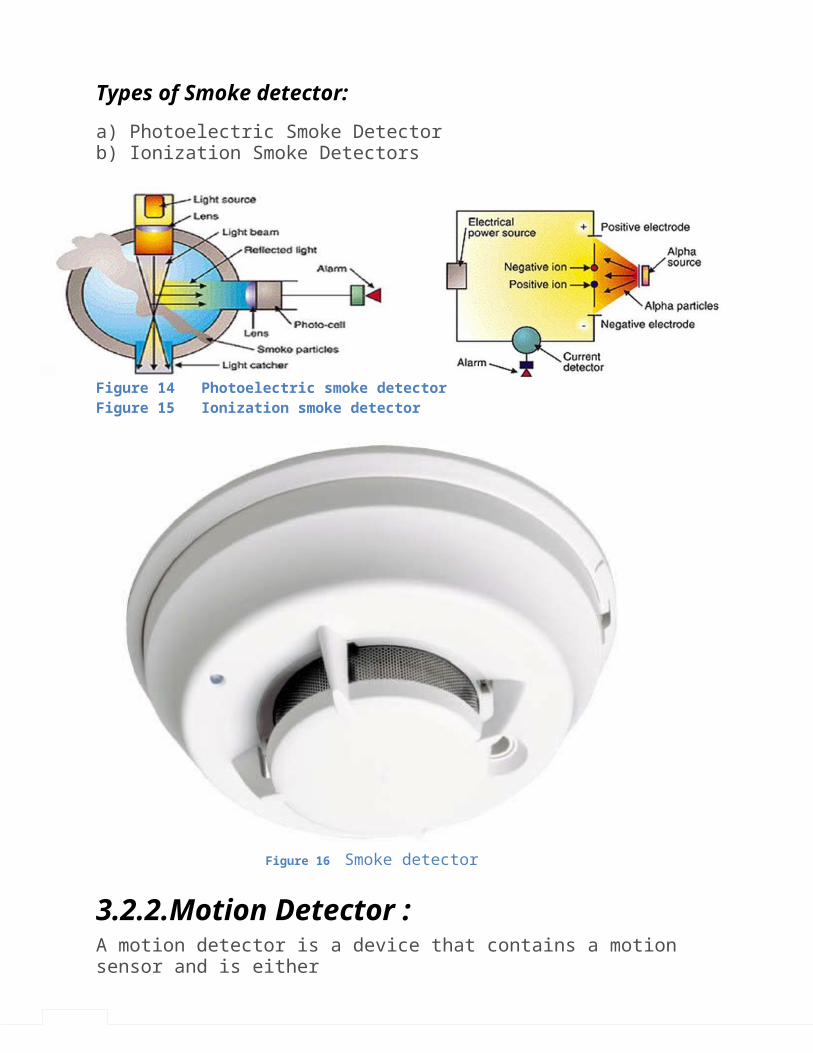
Types of Smoke detectors:a) Photoelectric Smoke Detector
b) Ionization Smoke Detectors
Location and spacing of automatic fire detectors:It is important to consult applicable local and national standards when choosing the
spacing and location of fire detectors. The following information is intended only
as a guide to the location and spacing of detectors.
Location and Spacing the sensors in the building :
Flat CeilingsOn a flat ceiling with no obstructions, the radius of protection of fire detectors is
7.5m for a smoke detector and 5.3m for a heat detector, and detectors should be
mounted a minimum of 0.5m from a wall. Some analogue multi-criteria detectors
have a heat sensor only function, switched by the control panel, typically used to
reduce the possibility of false alarms during daytime when a building is occupied,
reverting to multi- sensor operation at night time. If this type of operation is
employed, the radius of protection for a heat sensor should be used. Figure 13
gives a simple spacing plan based on these figures, however it should be noted that
this might not be the most efficient layout for a given site; for example in larger
areas, it is also possible to use a staggered layout, see figure 14, which may reduce
the number of detectors required. In practice, the layout of the room must be
considered to obtain the most efficient detector layout.

Figure 5
Smoke detectors
Where the ceiling is pitched or sloping, the slope of the roof tends to speed the rise of smoke or heat to the apex, hence reducing the delay before the detectors are triggered.
For sloped roofs with a pitch height greater than 600mm for smoke detectors, or 150mm for heat detectors, a row of detectors should be placed within a maximum vertical distance of 600mm or 150mm for smoke or heat detectors respectively from the roof apex. Sloped roofs rising less than 600mm for smoke detectors or 150mm for heat detectors may be treated as a flat ceiling.
Since the smoke or heat tends to rise faster up the slope, it is permissible to use a greater spacing for the row of detectors mounted in the apex of the roof: For each degree of slope of the roof, the spacing may be increased by 1% up to a maximum of 25%.

Figure 6 Smoke detectors
In corridors less than 2m wide, detectors should be spaced at a distance of 15m for smoke detectors and 10.6m for heat detectors, with the maximum dimension to a wall at the end of the corridor being 7.5m and 5.3m respectively .In narrow rooms and corridors greater than 2m wide, due to the way that the coverage radii of detectors intersect with the walls of the corridor, the spacing between detectors will increase.

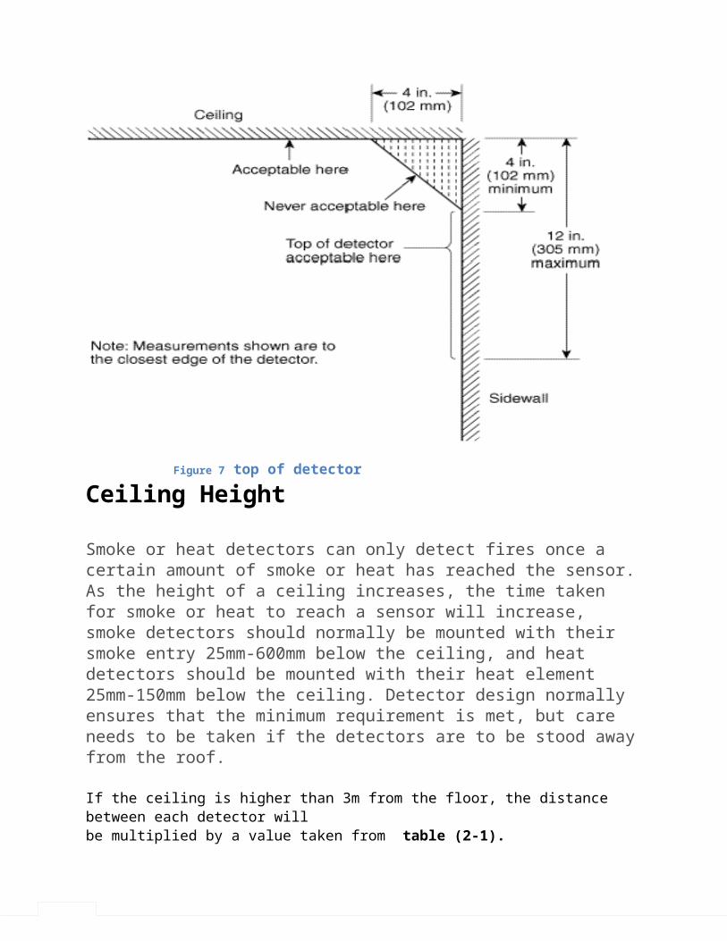
Ceiling Height
Smoke or heat detectors can only detect fires once a certain amount of smoke or heat has reached the sensor. As the height of a ceiling increases, the time taken for smoke or heat to reach a sensor will increase, smoke detectors should normally be mounted with their smoke entry 25mm-600mm below the ceiling, and heat detectors should be mounted with their heat element 25mm-150mm below the ceiling. Detector design normally ensures that the minimum requirement is met, but care needs to be taken if the detectors are to be stood away from the roof.
If the ceiling is higher than 3m from the floor, the distance between each detector willbe multiplied by a value taken from table (2-1).
Figure 7 top of detector
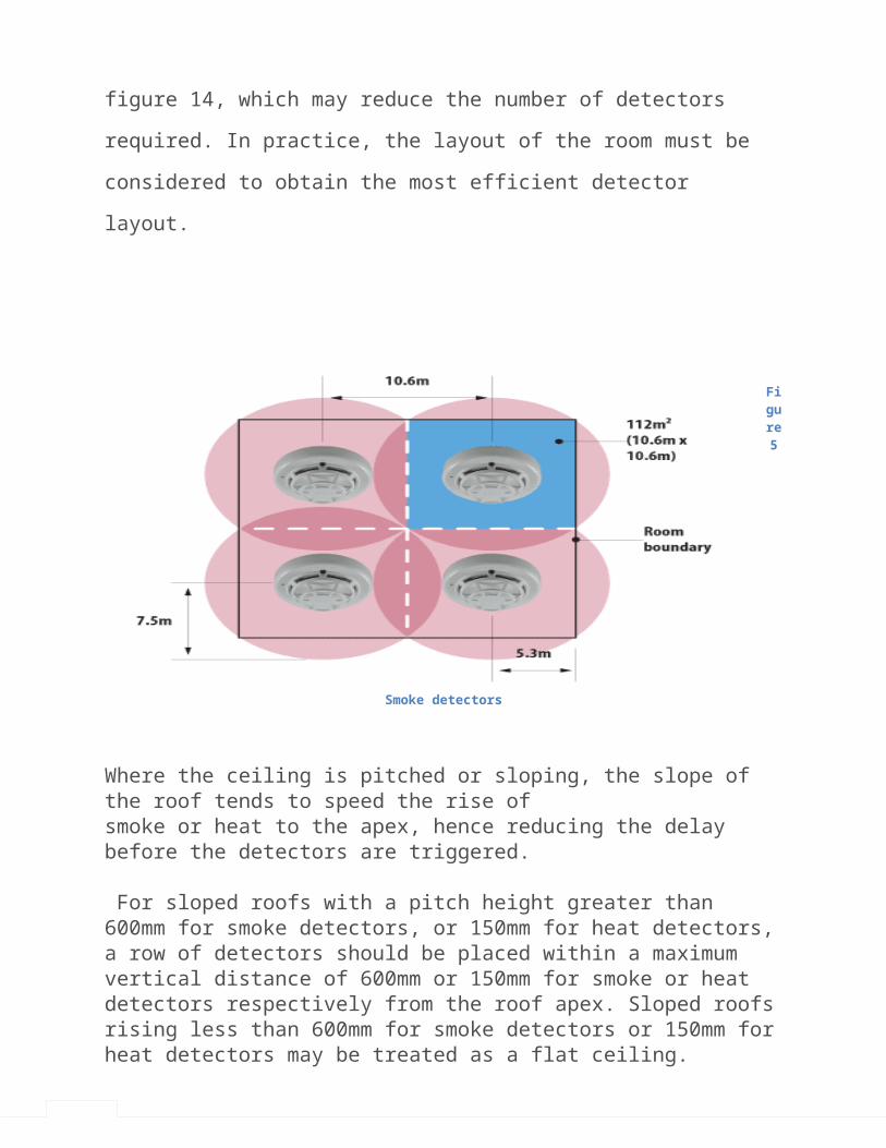
table (2-1).
Stairwells and Lift Shafts Internal stairwells and lift shafts and other vertical service ducts through a building
provide a clear path for smoke to pass between floors of a building as if they were
chimneys. It is therefore important to protect these, preferably using smoke
detectors. All vertical shafts through a building must be protected by a smoke or
heat detector at the top of the shaft, and by a detector within 1.5m of each opening
onto the shaft. In internal stairways, a detector should be mounted on each main
Ceiling height (m) Ceiling height (m) % of the described distance in between
From To
3 3.6 91 3.6 2.4 84 2.4 4.8 77 4.8 5.4 71 5.4 6 64 6 6.6 58 6.6 7.2 52 7.2 7.8 46 7.8 8.4 40 8.4 9 34

landing . In addition, if the detectors on the landings are separated by more than
10.5m, intermediate detectors should be mounted on the underside of the stairs.
Detectors should also be fitted into any room opening directly onto a stairway
other than a WC cubicle.
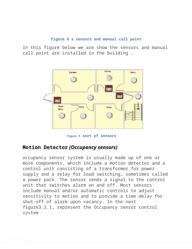
Figure 8 s sensors and manual call point
In this figure below we are show the sensors and manual call point are installed in the building .
Figure 9 sort of sensors
Motion Detector (Occupancy sensors)
occupancy sensor system is usually made up of one or more components, which include a motion detector and a control unit consisting of a transformer for power supply and a relay for load switching, sometimes called a power pack. The sensor sends a signal to the control unit that switches alarm on and off. Most sensors include manual and/or automatic controls to adjust sensitivity to motion and to provide a time delay for shut-off of alarm upon vacancy. In the next figure3.2.1, represent the Occupancy sensor control system
Sensor TypesThere are three type of sensor used: Passive Infra Red Sensors Passive infrared sensors (PIR) are triggered by the movement of a heat-emitting body through their field of view. PIR sensors cannot "see" through opaque walls, partitions, or windows so occupants must be in direct line-of-site of the sensor. Ultrasonic sensors Ultrasonic sensors emit an inaudible sound pattern that is disrupted by any moving object altering the signal returning to the sensor (Doppler shift). They are best suited for spaces where line-of-sight view to the occupant is not always available. This type of sensor detects very minor motion better than most infrared sensors. Dual-technology occupancy sensors Dual technology occupancy sensors use both passive infrared and ultrasonic technologies for less risk of false triggering (lights coming on when the space is unoccupied). Combining the technologies requires a more reliable, yet slightly larger and more expensive device. This type of sensors we will use it in our project’s

Network management system
In our project we have to secure the building ,this operation dependent on many parameter like fire detectors, anti theft detectors and cameras through monitor these parameter to main computer through a local network or internet, to connect the alarm panel to the network we use “XPORT DIRECT+” with the microcontroller and set an IP to every alarm panel and connect it to the network, this aims to detect the status of sensors in each panel through controlling the microcontroller from main computer that connected to internet in the local network in the facility, through this computer we can see the status of each sensor in the building , monitor the cameras and control the hole system. In the next topic we will show the benefits of network management system. The Benefits of Networked ManagementDevice Server technology allows an isolated device to be networkedinto the facility. There are several reasons for networking these devices:
1. Easy installation and maintenance
Network connections tend to be popular in every location in facilities. Like university, banks and other commercial buildings, This means that many device in

any location can be put onto the network and accessed from anywhere else on the local network or even over the Internet. As networks are extended to great lengths using switches, hubs,connectivity becomes available to areas that required long dedicated serial cable run.
2. Management from anywhere
Network managers now have a great many tools at their disposal forensuring that the network performs efficiently. SNMP (including MIBs) is a standardized management protocol providing pro-active management information arising from continuous process monitoring. Many vendors, such as HP (HPOpenview) and SUN (SunNetmanager), have welldeveloped software packages for network management, while most vendors support simple telnet or menu-based management interfaces. These protocols are supported over the Internet, allowing a network manager to roam at will, literally around the world, and still have access to a device.
3. Reliable management access
In most larger networks, 24-hour-a-day maintenance and monitoring takes place to ensure the network is running properly. Networking protocols designed for data delivery ensure that information arrives from node to node. Routed networks provide multiple pathways for data deliver . New software capable of measuring quality of service helps the network manager to tune the network topology to allow data to flow freely between devices virtually all the time. All of these reasons combine to make management over the network one of the most reliableways to manage a remote device.
4. Lower management costs
With a reliable remote management tool available, network managers can streamline their staffing and troubleshooting requirements toa centralized or even automated system. Standards-based managementfeatures such as SNMP maximize the investment in software and analysis devices based upon that protocol . Even a simple managementtechnique such as a ping or a telnet login to validate that a node is alive
can be run from a script. With a management scheme based upon established standards, network managers can train internal staff better and more easily hire new staff with known levels of skill regarding themanagement suite. Better management technology and better staff results in lower costs for the network manager.
Outputs (notifications).
Types of notification devicesa) Audible1. Bells2. Horns3. Sounder4. Chimes5. Speakers
They are designed to produce very loud and hard sound when activatedThey are available in many shapes and sizes .
b) Visual
1. Strobes2. FlasherVisual signaling appliances are used in high noise environments or in areas where audible devices may not be desirable.

Shapes of visual devices
After choosing the type of sensors we need in our project and studying how to install it, now can we implement our project and we can apply it in many application, and test the level of security.
3.Project component Pic 16F877. Sensors and detectors GSM Module Camera. Outputs

3.1.Microcontroller PIC16F877: Are general purpose microprocessors which have additional parts that allow them to control external devices. Basically, a microcontroller executes a user program which is loaded in its program memory. Under the control of this program, data is received from external devices (inputs), manipulated and then data is sent to external output devices. Programmable interrupt Controlling chip is used in our system to be the interface between the computer and the hardware. The main reason for choosing 16F877 microcontroller is the need for larger number of input/output ports. In figure 4.2 the pin diagram of the PIC16F877.

Figure 10Pin diagram of PIC16F877
MAX232: Since we can send and receive data at the same time due to the separate lines of sending and receiving data, the full-duplex mode block which enables this way of communication is called serial communication block, data moves here bit by bit, or in a series of bits what defines the term serial communication comes from. Figure 4.3shows the connection of MAX232 chip and the DB9 port.

Figure 11 interface RS232
I build the basic circuit of pic ,the following is the Schematic for basic circuit .
Tit le
S ize D o c u m e n t N um b e r R ev
D a t e : S he e t o f
<D o c > <R e v C o d e >
<Tit le >
E
1 1S a tu rd a y , A p r il 0 5 , 2 0 0 8
R E 0 / R D /A N 58
R E 1 / W R / AN 69
R E 2 / C S / A N 71 0
GN
D12
O S C 2 / C L KO U T1 4
R C 0 /T1 O S O /T1 C K I1 5
R C 1 / T1 O S I /C C P 21 6
R C 2 / C C P 11 7
R C 3 / SC K /S C L1 8
R D 0 / PS P 01 9
R D 1 / PS P 12 0
R D 2 / PS P 22 1
R D 3 / PS P 32 2
R C 4 /S D I /S D A2 3
R C 5 / S D O2 4
R C 6 / TX/ C K2 5
R C 7 / R X/ D T2 6
R D 4 / PS P 42 7
R D 5 / PS P 52 8
R D 6 / PS P 62 9
R D 7 / PS P 73 0
GN
D31
MC L R /V PP1
O S C 1 / C L KI N1 3
R A 0 / A N 02
R A 1 / A N 13
R A 2 / A N 24
R A 3 / A N 3 / V R E F5
R A 4 / TO C KI6
R A 5 / A N 4 / S S7
R B O / I N T3 3
R B 13 4
R B 23 5
R B 33 6
R B 43 7
R B 53 8
R B 63 9
R B 74 0
V D D1 1
V D D3 2
U 3
P IC 1 6 f 8 7 7
S W 1
S E R IA L S O C KE T
C 40. 1 u
1 2
J 1
In p u t V o lt ag e
S 8P ro g ra m
X14 MH z
D 1
1 N 4 0 0 7
C 8
1 2 p
C 9
1 2 p
R 13 3 K
C 1 26 .8 u
S 9R E S ET
C 1 10 . 1 u
C 1 00 . 1u
D 2L E D
C 31 u
C 51 u
C 61 u
V IN1
GN
D2
V O U T3
U 1 R e g u la t o r
C 71u
5V
C 11 0 u
C 20 .1 u
R 1 O U T1 2
T1 O U T1 4
T2 O U T7
T2 I N1 0 T1 I N1 1
G N D1 5
V C C1 6
R 1 I N1 3
R 2 I N8
R 2 O U T9
C 1 +1
C 1 -3
C 2 +4
C 2 -5
V +2
V -6
U 2
IC L2 3 2
Figure 12Basic circuit Schematic

• ULN2003: We use ULN2003 because that the PIC can only supply up to 25mA. This is fine for logic levels, and even small devices like LED's, but we can't drive a relay, motor, etc with a PIC. The ULN2003 is a very cost effective chip that acts like a switch. It simply switches an earth to/from an external circuit, and can withstand a continual 500mA current drain and a maximum 50V, as shown in figure 4.4.
Figure 13 • ULN2003
3.2.Sensors and Detectors:3.2.1.Smoke DetectorSmoke detectors are self-contained devices that can detect fire or smoke and set out analarm for the occupants of a building to evacuate its premises. Smoke alarms detect fire atan early stage. This gives individuals ample time to leave the building that has caughtfire. Hence, installing smoke alarms help to reduce casualties to a large extent and

ensures fire safety.
All smoke detectors consist of two basic parts: a sensor to sense the smoke and a very loud electronic horn to wake people up. Smoke detectors can run off of a 9-volt battery or 120-volt house current.
Types of Smoke detector:a) Photoelectric Smoke Detectorb) Ionization Smoke Detectors
Figure 14 Photoelectric smoke detector Figure 15 Ionization smoke detector
Figure 16 Smoke detector

3.2.2.Motion Detector :A motion detector is a device that contains a motion sensor and is eitherintegrated with or connected to other devices that alert the user of the pre-sense ofmotion. An electronic motion detector contains a motion sensor that transforms thedetection of motion into an electric signal. The electric signal can be connected to aburglar alarm system which is used to alert the home owner or security service afterit detects motion.
An example of sensor that used in security system is an active sensor. Activesensors in motion detectors system are commonly used inside homes for a securitysystem. An active motion detector emits optics or sound waves and measures feedback to detect motion. The simplest type of active motion detector is commonlyused in commercial doorways to trigger a doorbell.A device is fixed to one side of the doorway, an optical sensor to the other. Abeam of light will passes from the device through the sensor. When someone entersthe establishment, the beam is broken, triggering the doorbell thus warn user for theintrusion. For that reason, active motion detectors can be purchased for homeimprovement security system. It is inexpensive devices that can add for moresecurity to a home and provide peace of mind for home owners.
Types of Motion Detectors:
Active Infrared Motion Detector (IR)
Active infrared motion detectors use an IR sensor, as well as a source of radiation. The sensor is able to detect interruptions in the radiation it receives from the radiation source. This basically means that an IR motion detector is able to detect the signal of heat energy emitted by an intruder as it differs from the constant infrared scanning activity of the detector, as long as the intruder passes through it’s detection range.
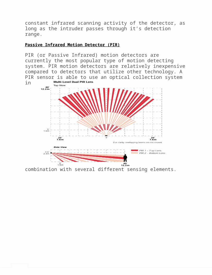
Passive Infrared Motion Detector (PIR)
PIR (or Passive Infrared) motion detectors are currently the most popular type of motion detecting system. PIR motion detectors are relatively inexpensive compared to detectors that utilize other technology. A PIR sensor is able to use an optical collection system in combination with several different sensing elements.
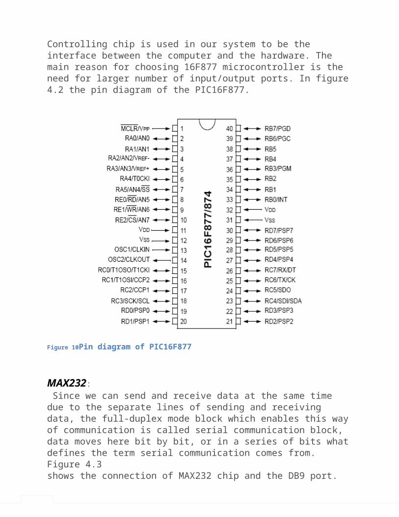
Figure 17 Motion Detectors
This allows the sensor to detect any changes that occur in ambient infrared radiation. The sensor is able to recognize a thermal infrared image (created by infrared technology combined with a heat sensor), which usually starts the transmission of an alarm signal back to the unit’s receiver. If the PIR sensor is connected to a monitored security system control panel, the control panel can interpret the alarm signal, and convert it into data to trigger the appropriate alarm.

Figure 18Motion Detectors
3.2.3.Manual Call PointTypes of fire boxes:1. Fire alarm pull station as shown in figure (2-14)2. Manual call point (break glass) as shown in figure (2.15)
Figure 19Manual Call Point
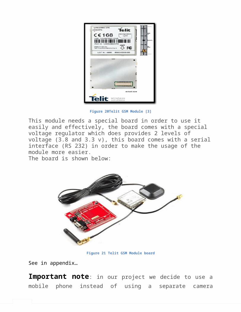
3.3.GSM ModuleThe GSM module is important in this kind of projects, it provides the ability to send and receive data between the desired machine and a fixed monitoring computer in the facility.[1]These are two important standards in the transfer of data using GSM network, the first one is the usage of SMS "Short Messages Service" and the second one is the usage of the General Packet Radio Service "GPRS".In our project we will use the GPRS as a communication way between the machine and the monitoring server, GPRS provides the ability to use the internet in sending and receiving data which will reduce the cost of transfer due to the usage of the packet switching in the case of GPRS.As an example of GSM modules we choose the Telit GM 862 GPS module which is shown in the following figure:
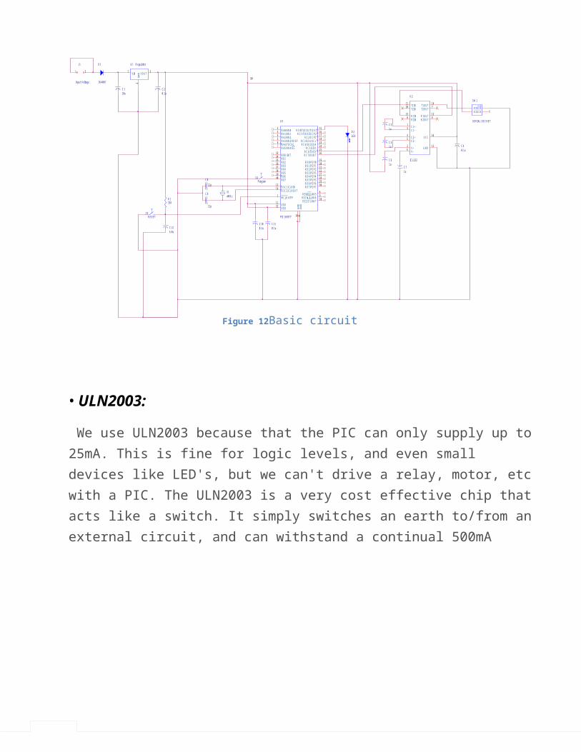
Figure 20Telit GSM Module [3]
This module needs a special board in order to use it easily and effectively, the board comes with a special voltage regulator which does provides 2 levels of voltage (3.8 and 3.3 v), this board comes with a serial interface (RS 232) in order to make the usage of the module more easier.The board is shown below:
Figure 21 Telit GSM Module board
See in appendix…
Important note: in our project we decide to use a mobile phone instead of using a separate camera interfaced with a GSM module, but for this reason we will need a special language called python language to control the operation of the mobile phone as we need in this project.

3.4. FTP SERVERFile Transfer Protocol (FTP) is a standard network protocol used to copy a file from one host to another over a TCP-based network, such as the Internet. FTP is built on a client-server architecture and utilizes separate control and data connections between the client and server.[1] FTP users may authenticate themselves using a clear-text sign-in protocol but can connect anonymously if the server is configured to allow it.[4]
See in appendix…
3.5.CameraIn our project we need a camera with suitable resolution to capture photos for the display of the elevator, in order to show the error code that appear when there is an error in the operation of the elevator system.
4.ImplementationHere we will discuss the progress of this project, and the steps that have been done and the steps that we are about to do on order to finish our project in the given time.This part of report will give the reader a clear vision about the stages of choosing, implementing and finishing this project.
4.1. Design procedureNow we will talk about the procedure of our system design:
At first we start by gathering the necessary information related to our project, and start learning the required programming languages like Python, PIC-C, and c++. Also how to use the required software that we need in our overall project.
We built the basic circuit of our microcontroller which is (PIC16F877A), and we wrote the necessary PIC-C codes to alarm system and to trigger the Python code, also to receive the control commands from the sensors and detectors and
work according to these commands. And interface the PIC with the Bluetooth module.
We built a house to simulate the project on it. We wrote the required Python code. We bought the FTP account. By an expert help, we designed a web-site and data base, to display the video.
We will divide the system operation flow into two main parts:
1. Case One: if there is someone in the house.2. Case Tow: if there is no one in the house.
4.1.1 Case One In normal conditions, the system is working, and the door, window, motion sensors are off, and only the smoke detector is on. The Python code waiting for a trigger signal if an error occurred for the fire detector only. Also, the Bluetooth connection between the microcontroller and the mobile is always up.
However, when an error occurred, the fire detector is going on which then send a signal to the microcontroller; the microcontroller will send an alarm and a special code to the mobile phone via Bluetooth to enable the Python code which in turns make the mobile to send a message to the owner and start record a video then upload this video to our account on the FTP server.
Then the system will be on until you reset it.
4.1.2. Case Tow On the other hand, if there is no one in the house the system is working too, but all sensors are worked (the door, window, motion sensors are off, and the smoke detector). The Python code waiting for a trigger signal if an error occurred for the fire detector only. Also, the Bluetooth connection between the microcontroller and the mobile is always up.
However, when an error occurred, the fire detector is going on which then send a signal to the microcontroller; the microcontroller will send an alarm and a special code to the mobile phone via Bluetooth to enable the Python code which in turns make the mobile

to send a message to the owner and start record a video then upload this video to our account on the FTP server.
Then the system will be on until you reset it.
5.Conclusion In our project we have discussed fire and theft alarm system and its components including detection devices, notification devices and other components.
We also discussed types, installation and application of detectors
Explain how each detector are work and where it is use.
Clarify the advantages and disadvantages of each type of detectors are used.
And finally we summarized our work in this semester in steps and set our goal in the coming semester by also putting a set of steps to be done during next semester. We hope that this report will give the reader a clear vision about what are we about to do.
6.Appendix:6.1. Introduction to GSM system
GSM (Global System for Mobile communications: originally from Groupe Spécial Mobile) is the most popular standard for mobile phones in the world. Its promoter, the GSM Association, estimates that 80% of the global mobile market uses the standard. GSM is used by over 3 billion people across more than 212 countries and territories. Its ubiquity makes international roaming very common between mobile phone operators, enabling subscribers to use their phones in many parts of the world. GSM differs from its predecessors in that both signalling and
speech channels are digital, and thus is considered a second generation (2G) mobile phone system. This has also meant that data communication was easy to build into the system. GSM EDGE is a 3G version of the protocol.[1]The ubiquity of the GSM standard has been an advantage to both consumers (who benefit from the ability to roam and switch carriers without switching phones) and also to network operators (who can choose equipment from any of the many vendors implementing GSM). GSM also pioneered a low-cost (to the network carrier) alternative to voice calls, the short message service (SMS, also called "text messaging"), which is now supported on other mobile standards as well. Another advantage is that the standard includes one worldwide emergency telephone number, This makes it easier for international travellers to connect to emergency services without knowing the local emergency number.Newer versions of the standard were backward-compatible with the original GSM phones. For example, Release of the standard added packet data capabilities, by means of General Packet Radio Service (GPRS). Release introduced higher speed data transmission using Enhanced Data Rates for GSM Evolution (EDGE).
6.2. SensorsThe most popular type of motion detecting system
Passive infrared (PIR) PIR sensors, the most commonly used type, are able to "see" heat emitted by occupants. Triggering occurs when a change in infrared levels is detected, as when a warm object moves in or out of view of one of the sensor's "eyes." PIR sensors are quite resistant to false triggering. They are best used within a 15-foot range for two reasons: first, there are potential "dead" spots between their wedge-shaped sensory patterns that get wider with distance (Figure 1); and, second, being passive, they do not send out any signal. Instead, PIR sensors depend on the intensity of the heat output of the moving part of the subject.PIRs are basically made of a pyroelectric sensor, which can detect levels of infrared radiation. Everything emits some low level radiation, and the hotter something is, the more radiation is emitted. The sensor in a motion detector is actually split in two halves. The reason for that is that we are looking to detect motion (change) not average IR levels. The two halves are wired up so that they cancel each other out. If one half sees more or less IR radiation than the other, the output will swing high or low..For many basic projects or products that need to detect when a person has left or entered the area, or has approached, PIR sensors are great. They are low power and low cost, pretty rugged,have a wide lens range, and are easy to interface with. Note that PIRs won't tell you how many people are around or how close they are to the sensor, the lens is often fixed to a certain sweep and distance (although it can be

hacked somewhere) and they are also sometimes set off by house pets.
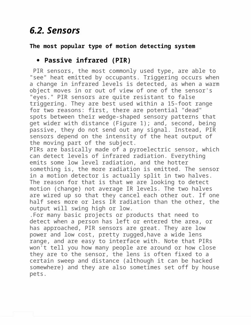
Figure 22 Sensor coverage diagram
Ultrasonic sensors can detect motion at any point within the contour lines. Infrared sensors see only in the wedge-shaped zones, and they don't generally see as far as ultrasonic units. The ranges are representative; actual sensors may be more or less sensitive.
Ultrasonic (US) Ultrasonic sensors emit a high-frequency (more than 20,000 cycles per second) sound above human and animal audibility ranges and listen for a change in frequency of the reflected sound. Because they emit a signal instead of receiving it, they are able to cover larger areas than PIR sensors and are more sensitive. US sensors are prone to false triggering and can be set off by air movement, such as that produced by a person running by a door or the on-off cycling of an HVAC system.Microwave and audible sound sensors are less common. Audible sound sensors, which listen for noise made by people or machines, are best applied in an industrial facility or warehouse. Microwave sensors are similar to ultrasonics, in that they emit a signal and measure a change in frequency when that signal is reflected. However, they are seldom used, and little is known about their effectiveness.
Hybrid or dual-technology sensors Incorporate features of both PIR and US sensors—or of other sensor types, such as microwave—in one sensor. The most common combination of sensor types is that of PIR and ultrasonic sensors, to take advantage of the PIR units' resistance to false triggering and the sensitivity of ultrasonics.

PIR (pyroelectric infrared) sensors are extremely useful for detecting the presence of a moving body. This is due to their ability to sense the infrared radiation that every living body emits. Though they have a relatively simple construction, there are various subtleties that need to be considered if these devices are to be applied to a system design correctly.
Reference:
Door Sensor:
Door sensors will trigger the alarm when the door is opened. These should be installed at every exterior door including the door to the garage. These sensors can also be used as a door chime which makes a quick beep when a door is opened and the alarm is not active. Installing the round plug style sensors can void the warranty on your door and your builder may not let you install them until you have purchased the home. You could use window style sensors on a door (although they will not be hidden) or you could pre-wire the sensor and drill the hole in the door later after you move in.
Window Sensor:
Window sensors will trigger the alarm when the window is opened. Having a separate channel for each window will quickly use up all the available channels on your alarm panel (this is covered in the Alarm Planning guide). Unlike door sensors, these sensors are visible on the window. There are types of window sensors that are hidden, but drilling into a window to hide a magnet is usually a very bad idea. You will probably break the seal on your window and any drilling in the window will void the warranty. Your best bet is to use 2-way tape to attach the sensor to the window so that no drilling is required. Sometimes you may want to activate the alarm at night even though a bedroom window is open. This can be done, but obviously that window is not protected by the alarm. Using motion detectors may be a better option.
Motion Detector:
Motion detectors will trigger the alarm when they detect motion in their area of coverage. Typically these are not installed on the second floor. You don't want the alarm going off when someone goes to the bathroom in the middle of the night. Motion detector usually have 90 degree area of coverage, so installing them in the corner of the room works best. Motion detectors should be installed in every major room of the home and if necessary they should also protect the alarm panel (in the basement or a utility closet). I prefer to install the motion detectors near the 4 exterior corners of the first floor so that they also cover the hallways. In an existing home you may choose to install them on an interior wall so that you don't have to deal with insulation when running the wires. Some motion detectors will detect small pets and set off the alarm, while others are designed ignore pets up to 40 or even 80 pounds. Be sure to review the specifications of the sensor before purchasing. Note: Usually motion detectors are referred to as PIR (Passive InfraRed) sensors. Some sensors utilize both PIR and microwave sensors for increased reliability.
Glass Break Sensor:
A glass break sensor will trigger the alarm when it detects the noise or vibration of glass breaking. The model on the left is attached directly to the window and can only determine if that window is broken. These are usually used by businesses on large plate glass windows. The model on the right can detect any glass breaking within a given distance and are usually mounted toward the center of the home or near an area with a lot of windows. In the example floor plan above, the glass break sensor is facing the rear exit glass door. Dropping a glass or loud noises can sometimes trip a glass break sensor and set off the alarm. The quality and sensitivity setting of the alarm control this behavior.
Water Sensor:
Water sensors are used to alert you or your alarm monitoring company in case there is a water leak. Typically, water problems occur in the laundry room when one of the flexible hoses to the washer bursts, in the basement near the sump pump, or near the furnace if the water runoff from the air conditioner backs up. Some water sensors / alarm systems are capable of turning off the water when a leak is detected. Since the sump pump should be near the lowest part of the basement, if you only have one sensor in the basement it should be near the sump pump.
Vibration Motion Detector
A motion detector that detects simple vibration can either be made from materials at home, or purchased as an electrical device. Most vibration motion sensors use the peizoelectric effect (the ability of some materials to generate an electric field) in order to detect motion. Simple do-it-yourself vibration sensors most commonly use a lever that activates a switch when it detects vibration.
Heat detectors.
It’s the fire detector that detects either abnormally high temperature or rate oftemperature rise, or both.It can be divided into:a) Fixed temperature heat detector

A device that responds when it’s operating element becomes heated to a predeterminedLevel.
Spot type
Figure 23
Physical principles of spot type heat detecting
1. Expansion of heated material2. Melting of heated material3. Changes in resistance of heated material
Bimetal typeUses 2 metals with different thermal expansion characteristics, when heated, onemetal expands faster than the other causing the strip to bend or arch.Deflection of strip makes or breaks alarm circuit, initiating an alarm automaticallywhen cooled. Figure(26)
Disadvantage of spot type fixed temperature heat detector1. It has low sensitivity.2. Designed for one time operation and the element need to be replaced.
b) Rate-of-rise heat detector

A device that responds when the temperature rises at a rate exceeding apredetermined valueThe rate of rise heat detector responds to a rate of temperature 15C per minute.
The disadvantage of R-O-R heat detectorSlow burning or smoldering combustion may produce considerable heat, and the ceiling where the detector is located may rise to high temperature, but unless the rate of increase of temperature is rapid enough to produce a 15C per minute, the detector will not activate.To avoid this disadvantage combination fixed temperature and rate of rise heat detector are used. Factors affecting heat detector performance
1. Very high temperature or very low temperature in the room.2. Ceiling height, because the detector senses the temperature when the flame reaches to third of the distance between fire place and the ceiling.
Heat detector installation requirements according to the Egyptian code
1. Must take into account the movement of air currents inside the building as the face of detectors to the renewable air currents, reduce its response.2. It requires installing more detectors at places that the air changes are more than four times per hour.3. It can’t be install the detector faced to the air conditioning unit, and generally thedistance between the detector and the air outlet shouldn’t be less than 1m.4. For the fixed temperature heat detector the operating temperature must not be less than the normal temperature of the place to be protected by 14C, and not more than28C.5. The heat detector height must not exceed 9m from the floor at the normal temperature and not exceed 6m at high temperature, in all cases; you should refer to the manufacturer's instructions.6. You need install more than one alarm when the length of your hall exceeds 9m.7. The spot heat detectors should be installed so that the sensing unit spreading out from the ceiling by 50mm8. The distance between each detector must not exceed 7m.9. The heat detector installed under the ceiling by a space not less than 10cm, it can alsobe installed on the wall by a space ranging from 10 to 30 cm.
Heat detectors applications1. When the smoke can’t be used.2. In very dusty, dirty, or greasy areas.3. In very damp, humid or steamy areas.4. Near fanner.

Flame detector.
A flame detector is a detector that uses optical sensors to detect flames, it can detect the1. Fire alarm pull station 2.Manual call point (break glass)
infra-red, ultraviolet or visible radiation produced by a fire. Flam detector is a radiant energy–sensing fire detector that detects the radiant energy emitted by a flame.Detectors work according to wavelengths to detect fires and explosions withinmilliseconds. Most sensitive to detect fires, but also easily activated by non-fireconditions (e.g. welding, sunlight etc.)These detectors must be positioned with an unobstructed view of the protected area andwill not activate if line of site is blocked.
Flame detectors regions
6.3.FTP SERVERFile Transfer Protocol (FTP) is a standard network protocol used to copy a file from one host to another over a TCP-based network, such as the Internet. FTP is built on aclient-server architecture and utilizes separate control and data connections between the client and server. FTP users may authenticate themselves using a clear-text sign-in protocol but can connect anonymously if the server is configured to allow it.[4]
Figure 24Flame detectors regions

The protocol is specified in RFC 959, which is summarized below.
A client makes a TCP connection to the server's port 21. This connection, called the control connection, remains open for the duration of the session, with a second connection, called the data connection, either opened by the server from its port 20 to a negotiated client port (active mode) or opened by the client from an arbitrary port to a negotiated server port (passive mode) as required to transfer file data. The control connection is used for session administration(i.e., commands, identification, passwords) exchanged between the client and server using a telnet-like protocol. For example "RETR filename" would transfer the specified file from the server to the client. Due to this two-port structure, FTP is considered an out-of-band, as opposed to an in-band protocol such as HTTP.
The server responds on the control connection with three digit status codes in ASCII with an optional text message, for example "200" (or "200 OK.") means that the last command was successful. The numbers represent the code number and the optional text represent explanations (e.g., <OK>) or needed parameters (e.g., <Need account for storing file>). A file transfer in progress over the data connection can be aborted using an interrupt message sent over the control connection.
FTP can be run in active or passive mode, which will determine how the data connection is established. In active mode, the client sends the server the IP address and port number on which the client will listen, and the server initiates the TCP connection. In situations where the client is behind a firewall and unable to accept incoming TCP connections, passive mode may be used. In this mode the client sends a PASV command to the server and receives an IP address and port number in return. The client uses these to open the data connection to the server. Both modes were updated in September 1998 to add support for IPv6. Other changes were made to passive mode at that time, making it extended passive mode.
Figure 25 FTP Servers
6.4.Python languagePython supports multiple programming paradigms, primarily but not limited to object-oriented, imperative and, to a lesser extent, functional programming styles. It features a fully dynamic type system and automatic memory management, similar to that of Scheme, Ruby, Perl, and TCL. Like other dynamic languages, Python is often used as a scripting language, but is also used in a wide range of non-scripting contexts.[5]
The reference implementation of Python (CPython) is free and open source software and has a community-based development model, as do all or nearly all of its alternative implementations. CPython is managed by the non-profit Python Software Foundation.
Python interpreters are available for many operating systems, and Python programs can be packaged into stand-alone executable code for many systems using various tools.
Python is often used as a scripting language for web applications, e.g. via mod_wsgi for the Apache web server. With Web Server Gateway Interface, a standard API has been developed to facilitate these applications. Web application frameworks like Django, Pylons, TurboGears, web2py, Flask and Zope support developers in the design and maintenance of complex applications. Libraries like NumPy, SciPy and Matplotlib allow Python to be used effectively in scientific computing.[5]
Python has been successfully embedded in a number of software products as a scripting language, including in finite element method software such as Abaqus, 3D animation packages such as Houdini, Maya, MotionBuilder, Softimage, Cinema 4D, BodyPaint 3D, modo and Blender and 2D imaging programs like GIMP, Inkscape, Scribus and Paint Shop Pro. GNU GDB uses Python as a pretty printer to show complex structures such as C++ containers. ESRI is now promoting Python as the best choice for writing scripts in ArcGIS. It has even been used in several video games and has been adopted as one of the two available scripting languages in Google Docs.
For many operating systems, Python is a standard component; it ships with most Linux distributions, NetBSD, OpenBSD and with Mac OS X and can be used from the terminal. A number of Linux distributions use installers written in Python: Ubuntu uses the Ubiquity installer, while Red Hat Linux and Fedora use the Anaconda installer. Gentoo Linux uses Python in its package management system, Portage and the standard tool to access it, emerge. Pardus uses it for administration and during system boot.[5]
Python has also seen extensive use in the information security industry, including exploit development.
Among the users of Python are YouTube and the original BitTorrent client. Large organizations that make use of Python include Google, Yahoo!, CERN, NASA and ITA. Most of the Sugar software for the One Laptop per Child XO, now developed at Sugar Labs, is written in Python.
Fans of Python use the phrase "batteries included" to describe the standard library, which covers everything from asynchronous processing to zip files. The language itself is a flexible powerhouse that can handle practically any problem domain. Build your own web server in three lines of code. Build flexible data-driven code using Python's powerful and dynamic introspection capabilities and advanced language features such as meta-classes, duck typing and decorators.
Python lets you write the code you need, quickly. And, thanks to a highly optimized byte compiler and support libraries, Python code runs more than fast enough for most applications.