Embed Size (px)
Citation preview
International Journal of Scientific & Engineering Research, Volume 5, Issue 6, June-2014 100 ISSN 2229-5518
IJSER © 2014 http://www.ijser.org
Current Research trends in Electric Discharge Machining(EDM):Review
Shaaz Abulais Division of Manufacturing Processes & Automation Engineering, NSIT
University of Delhi [email protected]
Abstract- Electrical discharge machining (EDM) is one of the earliest non-traditional machining processes. EDM process is based on thermoelectric energy between the work piece and an electrode. A pulse discharge occurs in a small gap between the work piece and the electrode and removes the unwanted material from the parent metal through melting and vaporising. The electrode and the work piece must have electrical conductivity in order to generate the spark. There are various types of products which can be produced using EDM such as dies and moulds. Parts of aerospace, automotive industry and surgical components can be finished by EDM. This paper reviews the research trends in EDM on ultrasonic vibration, dry EDM machining, EDM with powder additives, and EDM in water.
Index Terms - Electric Discharge Machining, Dry EDM, Wire EDM, Ultrasonic EDM, EDM with powder additives, EDM in water, Kerf Width, Spark Gap
1.INTRODUCTION Electrical discharge machining (EDM) is a non-traditional concept of machining which has been widely used to produce dies and moulds. It is also used for finishing parts for aerospace and automotive industry and surgical components.[1] This technique has been developed in the late 1940s [2] where the process is based on removing material from a part by means of a series of repeated electrical discharges between tool called the electrode and the work piece in the presence of a dielectric fluid[3] . The electrode is moved toward the work piece until the gap is small enough so that the impressed voltage is great enough to ionize the dielectric[4] . Short duration discharges are generated in a liquid dielectric gap, which separates tool and work piece. The material is removed with the erosive effect of the electrical discharges from tool and work piece[5]. EDM does not make direct contact between the electrode and the work piece where it can eliminate mechanical stresses, chatter and vibration problems during machining [1]. Materials of any hardness can be cut as long as the material can conduct electricity[6] . EDM techniques have developed in many areas. • Shaaz Abulais is pursuing B.E. in Manufacturing
Processes & Automation Engineering in NSIT, Delhi, University of Delhi, India, PH- 9891786347.E-mail: [email protected]
1.1 Working Principle of EDM
The working principle of EDM process is based on the thermoelectric energy. This energy is created between a workpiece and an electrode submerged in a dielectric fluid with the passage of electric current. The workpiece and the electrode are separated by a specific small gap called spark gap.[7-9] Pulsed arc discharges occur in this gap filled with an insulating medium, preferably a dielectric liquid like hydrocarbon oil or de-ionized (de-mineralized) water. Schumacher described the technique of material erosion employed in EDM as still arguable.[10] This is because ignition of electrical discharges in a dirty, liquid filled gap, when applying EDM, is mostly interpreted as ion action identical as found by physical research of discharges in air or in vacuum as well as with investigations on the breakthrough strength of insulating hydrocarbon liquids. The working principle of EDM is shown in Fig. 1. This technique has been developed in the late 1940s[11] . The electrode moves toward the workpiece reducing the spark gap so that the applied voltage is high enough to ionize the dielectric fluid[12]. Short duration discharges[13] are generated in a liquid dielectric gap, which separates electrode and workpiece. The material is removed from tool and workpiece with the erosive effect of the electrical discharges. The dielectric fluid serves the purpose to concentrate the discharge energy into a channel of very small cross sectional areas. It also cools the two electrodes, and flushes away the products of machining from the gap. The electrical resistance of the dielectric influences the discharge energy and the time of spark initiation[14] . Low resistance results in early discharge. If resistance is large, the capacitor will attain a higher charge value before initiation of discharge. A servo system is employed which compares the gap voltage with a reference value and to ensure that the electrode moves at a proper rate to maintain the right spark
IJSER

International Journal of Scientific & Engineering Research, Volume 5, Issue 6, June-2014 101 ISSN 2229-5518
IJSER © 2014 http://www.ijser.org
gap, and also to retract the electrode if short-circuiting occurs. When the measured average gap voltage is higher than that of the servo reference voltage, preset by the operator, the feed speed increases. On the contrary, the feed speed decreases or the electrode is retracted when the average gap voltage is lower than the reference voltage, which is the case for smaller gap widths resulting in a smaller ignition delay. Thus short circuits caused by debris particles and humps of discharge a crater are avoided. Also quick changes in the working surface area, when tool shapes are complicated, does not result in hazardous machining. In some cases, the average ignition delay time is used in place of the average gap voltage to monitor the gap width[15]. The RC circuit employed in EDM did not give good material removal rate, and higher material removal rate was possible only by sacrificing surface finish. A major portion of the time of machining was spent on charging the capacitors as shown in Fig. 2.[16]
Figure 1: Working principle of EDM
However, the review presented in this report is on current EDM research trends carried out by researchers on machining techniques viz. ultrasonic vibration, dry EDM machining, EDM with powder additives and EDM in water.
Figure 2: Variation of Capacitor voltage
2. EDM using Ultrasonic Machining
Introduction of ultrasonic vibration to the electrode is one of the methods used to expand the application of EDM and to improve the machining performance on difficult to machine materials. The study of the effects on ultrasonic vibration of the electrode on EDM has been undertaken since mid 1980s. The higher efficiency gained by the employment of ultrasonic vibration is mainly attributed to the improvement in dielectric circulation which facilitates the debris removal and the creation of a large pressure change between the electrode and the work piece, as an enhancement of molten metal ejection from the surface of the work piece[17] . Zhang et al.[18] proposed spark erosion with ultrasonic frequency using a DC power supply instead of the usual pulse power supply. The pulse discharge is produced by the relative motion between the tool and work piece simplifying the equipment and reducing its cost. They have indicated that it is easy to produce a combined technology which benefits from the virtues of ultrasonic machining and EDM.
IJSER

International Journal of Scientific & Engineering Research, Volume 5, Issue 6, June-2014 102 ISSN 2229-5518
IJSER © 2014 http://www.ijser.org
2.1 Machining of Microholes In 1995 Zhixin et al.[19] has developed an ultrasonic vibration pulse electro-discharge machining (UVPEDM) technique to produce holes in engineering ceramics material. They have confirmed by experiment that this new technique is effective in obtaining a high material removal rate (MRR). Ogawa et al.[20] proved that the depth of microholes by EDM with ultrasonic vibration becomes as about two times as that without ultrasonic vibration and machining rate increased. Thoe et al. [21]dealt with combined ultrasonic and electrical discharge machining of ceramic coated nickel alloy. They found the following: when drilling 1mm diameter single hole using various tool materials (tungsten, silver steel, mild steel and copper) with boron carbide abrasive slurry on ceramic coated nickel alloy work piece, mild steel is found to be the most resilient
whereas the other materials fail as a result of fatigue fracture or deformation. Using ultrasonic vibration during EDM greatly increased the MRR of the work piece. Wansheng et al. [22]introduces ultrasonic vibration into micro-EDM: Ti–6Al–4V as work piece material with 32mm thickness, carbide YG6X electrode, 20 kHz ultrasonic vibration and 2 mm amplitude; holes with diameter of 0.2mm and depth/diameter ratio of more than 15 can be drilled. 2.2 Micro-EDM Electro discharge machining (EDM) is a known and widely used nonconventional machining process for hard to cut materials because of its ability to function independently of the hardness, brittleness or toughness of the workpiece. Using low energies, it has been successfully applied in micro- and precision machining, for example, in the mould
making industry. Higher accuracies in smaller and more complex structures demand an extremely stable process and therefore enhanced flushing techniques. Additionally, more and more high-tech materials such as ceramics are being used for micro parts; this presents an opportunity to apply μ-EDM in that emerging material area. 2.3 PROCESS PRINCIPLE The electro discharge machining process is based on ablation of material through melting and evaporation. The figure below shows the process principle. The electrical
discharges take place between the tool electrode and the workpiece in a dielectric medium that separates the two. A voltage is applied to both electrodes and, when the breakdown voltage of the medium is reached, a plasma channel allowing for a current flow is established and a discharge takes place. At the base of the plasma channel the temperature can reach T ≥ 10,000 °K, melting and evaporating the electrode material. When the energy input is stopped the discharge ends, leading to a collapse of the plasma channel and the surrounding gas bubble. The reflow of the dielectric medium flushes liquid material away and cools the electrode surface. Repeating the process, a
IJSER

103 International Journal of Scientific & Engineering Research Volume 5, Issue 6, June-2014 ISSN 2229-5518
IJSER © 2014 http://www.ijser.org
voltage is attached to the electrodes again and the setup is prepared for the next discharge. Naturally, the discharge will take place where the breakdown barrier is lowest, that is when the distance between the electrodes is the smallest – in an ideal dielectric – or, in a real dielectric liquid, when the conductivity of the gap between the electrodes is the highest, e.g. when particles or gas bubbles reduce the breakdown voltage of the medium. By constant repetition of the process, the tool electrode surface is reassembled in the workpiece and, by feeding the tool, a transfer of the geometry takes place. Because of the
process nature, the surface is an assembly of single discharges and shows a crater-like topology. The geometrical accuracy and the surface roughness depend on the size and shape of these craters and therefore on the volume that is ablated with each discharge. A minimisation of discharge energy is the key to precision and optimal surface characteristics. Consequently, the discharge gap must be minimised, too. In μEDM, the discharges have a typical duration of te ≈ 100 ns and transfer energy of We ≈ 10 μJ. The resulting crater width depends on the workpiece material properties, but a diameter of dC ≈ 5 μm and depth of ≤1 μm can usually be obtained. The resulting surface roughness can be as low as Rz ≤ 1μm.
A major benefit of the electro discharge machining process, due to its electro-thermal nature of ablation, is independency of material hardness and brittleness. The noncontact nature of the process results in a nearly force-free machining, allowing the usage of soft, easy to machine electrode materials even when shaping very hard workpieces.
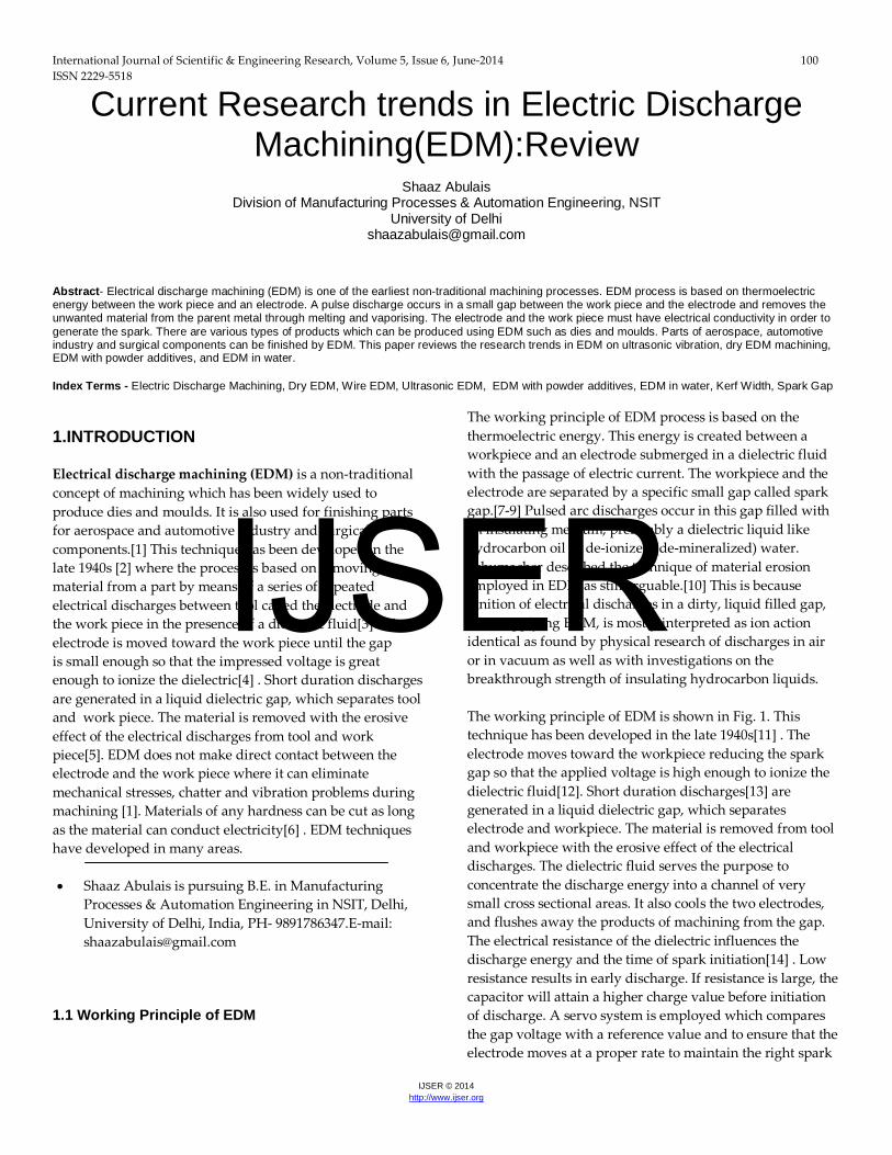
This also enables the machining of fragile or thin workpieces. Additionally, there is no limitation to the angle between the tool and workpiece, so round or irregularly shaped surfaces can be used. For all those reasons, EDM has been widely used in the generation of micro parts and geometries such as spinnerets (Fig. 2)[23]
IJSER
104 International Journal of Scientific & Engineering Research Volume 5, Issue 6, June-2014 ISSN 2229-5518
IJSER © 2014 http://www.ijser.org
Fig. 2. SEM image of non-circular micro bore Ø80 μm in hardened steel, manufactured using vibration-assisted μEDM
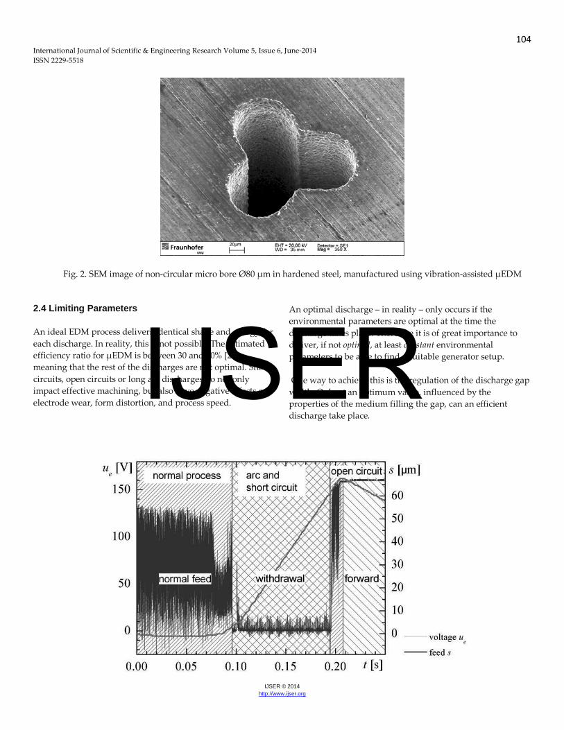
2.4 Limiting Parameters An ideal EDM process delivers identical shape and energy for each discharge. In reality, this is not possible. The estimated efficiency ratio for μEDM is between 30 and 50% [24], meaning that the rest of the discharges are not optimal. Short circuits, open circuits or long arc discharges do not only impact effective machining, but also have negative effects on electrode wear, form distortion, and process speed.
An optimal discharge – in reality – only occurs if the environmental parameters are optimal at the time the discharge takes place. Therefore it is of great importance to deliver, if not optimal, at least constant environmental parameters to be able to find a suitable generator setup. One way to achieve this is the regulation of the discharge gap width. Only at an optimum value, influenced by the properties of the medium filling the gap, can an efficient discharge take place.
IJSER
105 International Journal of Scientific & Engineering Research Volume 5, Issue 6, June-2014 ISSN 2229-5518
IJSER © 2014 http://www.ijser.org
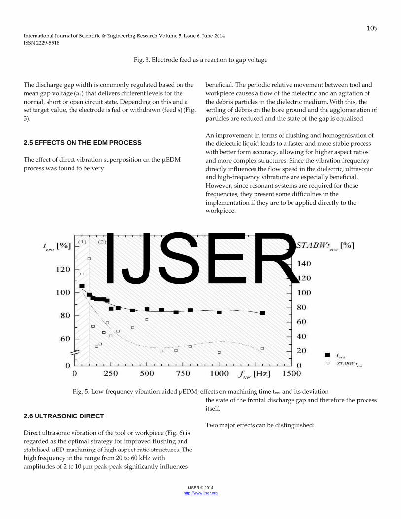
Fig. 3. Electrode feed as a reaction to gap voltage
The discharge gap width is commonly regulated based on the mean gap voltage (ue) that delivers different levels for the normal, short or open circuit state. Depending on this and a set target value, the electrode is fed or withdrawn (feed s) (Fig. 3). 2.5 EFFECTS ON THE EDM PROCESS The effect of direct vibration superposition on the μEDM process was found to be very
beneficial. The periodic relative movement between tool and workpiece causes a flow of the dielectric and an agitation of the debris particles in the dielectric medium. With this, the settling of debris on the bore ground and the agglomeration of particles are reduced and the state of the gap is equalised. An improvement in terms of flushing and homogenisation of the dielectric liquid leads to a faster and more stable process with better form accuracy, allowing for higher aspect ratios and more complex structures. Since the vibration frequency directly influences the flow speed in the dielectric, ultrasonic and high-frequency vibrations are especially beneficial. However, since resonant systems are required for these frequencies, they present some difficulties in the implementation if they are to be applied directly to the workpiece.
Fig. 5. Low-frequency vibration aided μEDM; effects on machining time tero and its deviation
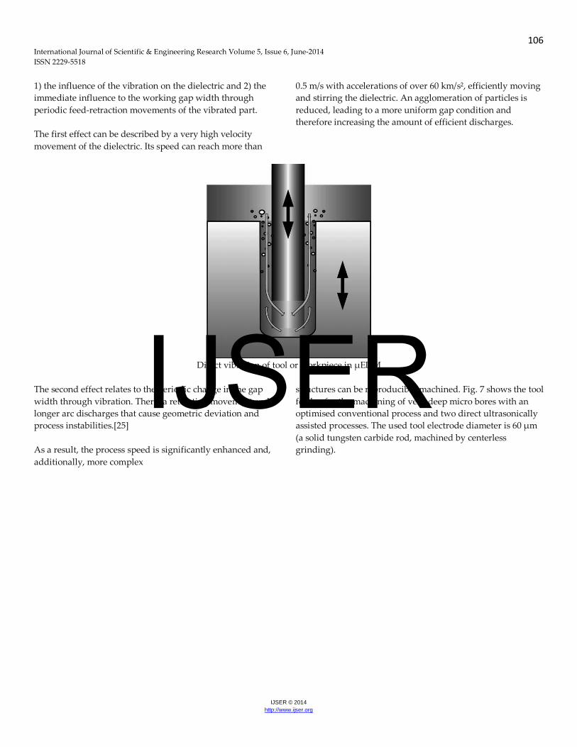
2.6 ULTRASONIC DIRECT Direct ultrasonic vibration of the tool or workpiece (Fig. 6) is regarded as the optimal strategy for improved flushing and stabilised μED-machining of high aspect ratio structures. The high frequency in the range from 20 to 60 kHz with amplitudes of 2 to 10 μm peak-peak significantly influences
the state of the frontal discharge gap and therefore the process itself. Two major effects can be distinguished:
IJSER
106 International Journal of Scientific & Engineering Research Volume 5, Issue 6, June-2014 ISSN 2229-5518
IJSER © 2014 http://www.ijser.org
1) the influence of the vibration on the dielectric and 2) the immediate influence to the working gap width through periodic feed-retraction movements of the vibrated part. The first effect can be described by a very high velocity movement of the dielectric. Its speed can reach more than
0.5 m/s with accelerations of over 60 km/s², efficiently moving and stirring the dielectric. An agglomeration of particles is reduced, leading to a more uniform gap condition and therefore increasing the amount of efficient discharges.
Direct vibration of tool or workpiece in μEDM
The second effect relates to the periodic change in the gap width through vibration. There, a retracting movement ends longer arc discharges that cause geometric deviation and process instabilities.[25] As a result, the process speed is significantly enhanced and, additionally, more complex
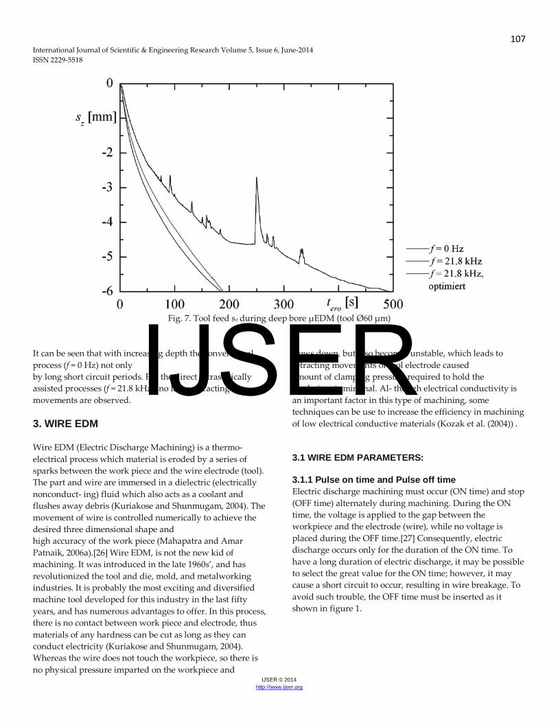
structures can be reproducibly machined. Fig. 7 shows the tool feed sz for the machining of very deep micro bores with an optimised conventional process and two direct ultrasonically assisted processes. The used tool electrode diameter is 60 μm (a solid tungsten carbide rod, machined by centerless grinding).
IJSER
107 International Journal of Scientific & Engineering Research Volume 5, Issue 6, June-2014 ISSN 2229-5518
IJSER © 2014 http://www.ijser.org
Fig. 7. Tool feed sz during deep bore μEDM (tool Ø60 μm) It can be seen that with increasing depth the conventional process (f = 0 Hz) not only
slows down, but also becomes unstable, which leads to retracting movements of tool electrode caused
by long short circuit periods. For the direct ultrasonically assisted processes (f = 21.8 kHz), no large retracting movements are observed. 3. WIRE EDM Wire EDM (Electric Discharge Machining) is a thermo- electrical process which material is eroded by a series of sparks between the work piece and the wire electrode (tool). The part and wire are immersed in a dielectric (electrically nonconduct- ing) fluid which also acts as a coolant and flushes away debris (Kuriakose and Shunmugam, 2004). The movement of wire is controlled numerically to achieve the desired three dimensional shape and high accuracy of the work piece (Mahapatra and Amar Patnaik, 2006a).[26] Wire EDM, is not the new kid of machining. It was introduced in the late 1960s’, and has revolutionized the tool and die, mold, and metalworking industries. It is probably the most exciting and diversified machine tool developed for this industry in the last fifty years, and has numerous advantages to offer. In this process, there is no contact between work piece and electrode, thus materials of any hardness can be cut as long as they can conduct electricity (Kuriakose and Shunmugam, 2004). Whereas the wire does not touch the workpiece, so there is no physical pressure imparted on the workpiece and
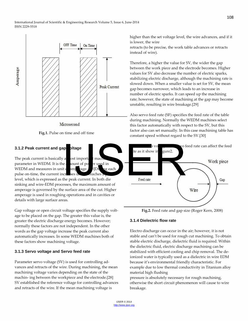
amount of clamping pressure required to hold the workpiece is minimal. Al- though electrical conductivity is an important factor in this type of machining, some techniques can be use to increase the efficiency in machining of low electrical conductive materials (Kozak et al. (2004)) . 3.1 WIRE EDM PARAMETERS: 3.1.1 Pulse on time and Pulse off time Electric discharge machining must occur (ON time) and stop (OFF time) alternately during machining. During the ON time, the voltage is applied to the gap between the workpiece and the electrode (wire), while no voltage is placed during the OFF time.[27] Consequently, electric discharge occurs only for the duration of the ON time. To have a long duration of electric discharge, it may be possible to select the great value for the ON time; however, it may cause a short circuit to occur, resulting in wire breakage. To avoid such trouble, the OFF time must be inserted as it shown in figure 1.
IJSER
108 International Journal of Scientific & Engineering Research Volume 5, Issue 6, June-2014 ISSN 2229-5518
IJSER © 2014 http://www.ijser.org
Fig.1. Pulse on time and off time
3.1.2 Peak current and gap voltage The peak current is basically a most important machining parameter in WEDM. It is the amount of power used in WEDM and measures in unit of amperage. [28]During each pulse on-time, the current increases until it reaches a preset level, which is expressed as the peak current. In both die sinking and wire-EDM processes, the maximum amount of amperage is governed by the surface area of the cut. Higher amperage is used in roughing operations and in cavities or details with large surface areas. Gap voltage or open circuit voltage specifies the supply volt- age to be placed on the gap. The greater this value is, the greater the electric discharge energy becomes. However; normally these factors are not independent. In the other words as the gap voltage increase the peak current also automatically increases. In some WEDM machines both of these factors show machining voltage. 3.1.3 Servo voltage and Servo feed rate Parameter servo voltage (SV) is used for controlling ad- vances and retracts of the wire. During machining, the mean machining voltage varies depending on the state of the machin- ing between the workpiece and the electrode.[28] SV established the reference voltage for controlling advances and retracts of the wire. If the mean machining voltage is
higher than the set voltage level, the wire advances, and if it is lower, the wire retracts (to be precise, the work table advances or retracts instead of wire). Therefore, a higher the value for SV, the wider the gap between the work piece and the electrode becomes. Higher values for SV also decrease the number of electric sparks, stabilizing electric discharge, although the machining rate is slowed down. When a smaller value is set for SV, the mean gap becomes narrower, which leads to an increase in number of electric sparks. It can speed up the machining rate; however, the state of machining at the gap may become unstable, resulting in wire breakage.[29] Also servo feed rate (SF) specifies the feed rate of the table during machining. Normally the WEDM machines select this factor automatically with respect to the SV, but this factor also can set manually. In this case machining table has constant speed without regard to the SV.[30] So both servo voltage and servo feed rate can affect the feed rate as it show in figure2.
Fig.2. Feed rate and gap size (Roger Kern, 2008)
3.1.4 Dielectric flow rate Electro discharge can occur in the air; however, it is not stable and can’t be used for rough cut machining. To obtain stable electric discharge, dielectric fluid is required. Within the dielectric fluid, electric discharge machining can be stabilized with efficient cooling and chip removal. The de-ionized water is typically used as a dielectric in wire EDM because it’s environmental friendly characteristic. For example due to low thermal conductivity in Titanium alloy material high flushing pressure is absolutely necessary for rough machining, otherwise the short circuit phenomenon will cause to wire breakage.
IJSER

109 International Journal of Scientific & Engineering Research Volume 5, Issue 6, June-2014 ISSN 2229-5518
IJSER © 2014 http://www.ijser.org
Figure3 show the cut- ting line while machining Titanium alloy (Ti6Al4V) in normal flushing pressure.[31] This figure shows in absence of high flashing pressure cutting line cannot continue more that 1mm.
Fig.3. Wire broken and small cutting line in Titanium
machining due to low flushing pressure
3.1.5 Wire speed or wire feed Wire speed is another important parameter in WEDM that show the speed of wire in WEDM. As the wire speed increase the wire consumption and in result the cost of machining will increase while low wire speed can cause to wire breakage in high cutting speed. 3.1.6 Wire tension Wire tension is the factor that can control the tension of wire in WEDM. If the wire tension is high enough the wire stays straight otherwise wire drags behind as it shown in figure 4. 3.2 DIFFERENT PROCESS RESPONSES 3.2.1 Material removal rate and cutting speed: Lots of research tried to maximize the material removal rate and cutting speed by different approaches. Because these factors can help to increase, economic benefits in WEDM considerably. Almost both of these factors (material removal rate and cutting speed) determine same phenomena which is the machining rate. MRR value normally obtained by the following equation: MRR= (W -W )/(T ×p) (mm3/sec) (1)
Rajurkar and Wang (1993)[32] analyzed the wire rupture phenomena with a thermal model and experimental investigations. It was found that the material removal rate in WEDM increases initially with the decrease of pulse off time. However,
Fig.4. Relation between wire drag and wire tension. at a very short pulse off time, the gap becomes unstable which leads to a reduction in the machining rate. 3.2.2 Kerf width and Sparking Gap Kerf width and sparking gap investigate the same phenomena as it shown in figure 5, and it is the measure of the amount of the material that is wasted during machining. It can determine the dimensional accuracy of the finishing part and the internal corner radius of the product in WEDM operations are also limited by this factor (Parashar .et.al, 2010).[33] Following equation normally use to determine the Sparking gap value: Sparking gap (mm) = (average of kerf width-diameter of wire)/2
IJSER

110 International Journal of Scientific & Engineering Research Volume 5, Issue 6, June-2014 ISSN 2229-5518
IJSER © 2014 http://www.ijser.org
Fig.5. Details of Sparking Gap
(Scott, 1991)
Parashar et.al (2010)[34] investigate the effects of WEDM parameters on kerf width while machining Stainless steel, it was found that pulse on time and dielectric flushing pressure are the most significant factors, while gap voltage, pulse off time and wire feed are the less significant factor on the kerf width. Tosun, N. et al. (2004) [35]presented an investigation on the level of impor- tance of the machining parameters on the kerf width by using ANOVA. It was found that open circuit voltage and pulse dura- tion were the highly effective parameters whereas wire speed and dielectric flushing pressure were less effective factors. According to this research open circuit voltage for controlling the kerf width was about three times more important than the second ranking factor (pulse duration). Swain,A.K., et al. (2012) [36]also studied the kerf width and it was found that just gap voltage is the significant factor that affect kerf width and pulse on time and pulse off time are insignificant. 3.3 DRY AND NEAR-DRY WIRE CUT There is a method in wire EDM which is conducted in a gas atmosphere without using dielectric liquid, this method called dry-WEDM. Recently, new method have introduced in WEDM which called Near-Dry Wire-Cut. In this method the liquid di- electric fluid is replaced by the minimum quantity of liquid with the gas mixture. (Boopathi, S. (2012)) Kunieda and Furudate (2001) [37]conducted studies in dry WEDM. It was found that in dry-WEDM, the vibration of the wire electrode is minimal due to the negligibly small process reaction force. In addition narrower gap distance and no corrosion for work piece during machining are the other advantages of dry
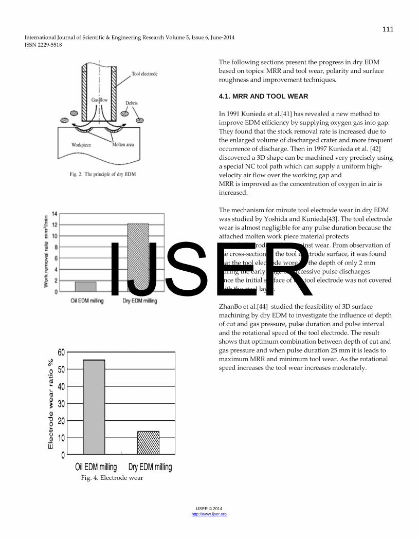
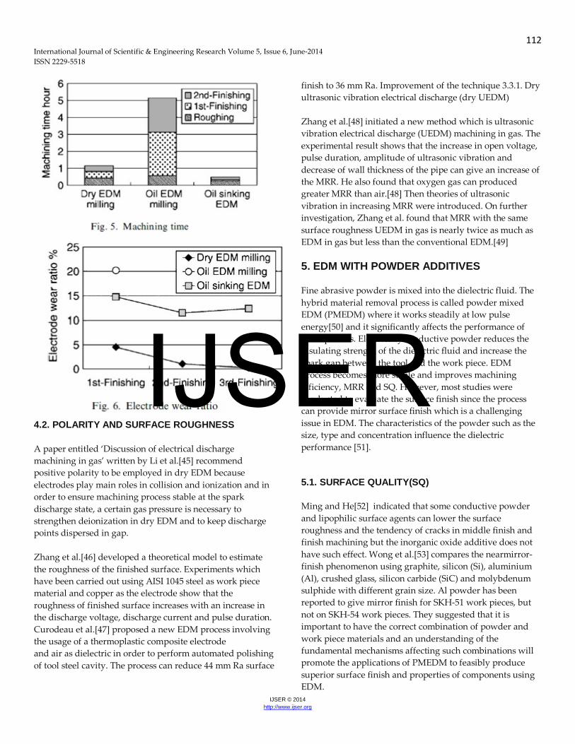
EDM. These characteristics can improve the accuracy and surface quality of workpiece during of finish cutting. The main drawbacks are lower material removal rate compared to conventional WEDM and streaks are more likely to be generated in this method. The drawbacks can be resolved by increasing the wire winding speed and decreasing the actual depth of cut. These re- sults are in agreement with other reports. For example Wang, T. et al. (2006 and 2008) [38]Studied finishing cut with Dry-WEDM and it was found that dry-WEDM have some advantage like better straightness, lower surface roughness and shorter gap length and the main disadvantage of this method was poorer material removal rate in compare with conventional method. In conflict with this study Abdulkareem, S., (2011)[39] investigated the effects of machining parameters on surface roughness in dry and wet wire- electrical discharge machining, It was found that wet WEDM gives better surface roughness compared to dry WEDM, it is to be noted that in this study normal machining have studied(not finishing process). 4. DRY EDM In dry EDM, tool electrode is formed to be thin walled pipe. High-pressure gas or air is supplied through the pipe. The role of the gas is to remove the debris from the gap and to cool the inter electrode gap. Fig. 2 shows the principle of dry EDM. The technique was developed to decrease the pollution caused by the use of liquid dielectric which leads to production of vapour during machining and the cost to manage the waste. Yu et al. [40] investigated the capability of the technique in machining cemented carbide material and compared the machining characteristics between oil EDM milling and oil die sinking EDM. They found that for machining the same shape oil die sinking EDM shows shorter machining time. But because oil die sinking requires time for producing electrodes, dry EDM should be more useful in actual production. The information given in this paper is interesting and they are reproduced here for better clarity. Figs. 3 and 4 show the work removal rate and electrode wear ratio in groove machining. According to the results,work removal rate of dry EDM milling is about six times larger than that of oil EDM milling, and electrode wear ratio one-third lower. In Fig. 5, it is shown that the EDM method with the shortest machining time was oil die sinking EDM, dry EDM milling was second, and oil EDM milling third. The lowest electrode wear ratio machining was dry EDM milling ( Fig. 6).
IJSER
111 International Journal of Scientific & Engineering Research Volume 5, Issue 6, June-2014 ISSN 2229-5518
IJSER © 2014 http://www.ijser.org
Fig. 4. Electrode wear
The following sections present the progress in dry EDM based on topics: MRR and tool wear, polarity and surface roughness and improvement techniques. 4.1. MRR AND TOOL WEAR In 1991 Kunieda et al.[41] has revealed a new method to improve EDM efficiency by supplying oxygen gas into gap. They found that the stock removal rate is increased due to the enlarged volume of discharged crater and more frequent occurrence of discharge. Then in 1997 Kunieda et al. [42] discovered a 3D shape can be machined very precisely using a special NC tool path which can supply a uniform high-velocity air flow over the working gap and MRR is improved as the concentration of oxygen in air is increased. The mechanism for minute tool electrode wear in dry EDM was studied by Yoshida and Kunieda[43]. The tool electrode wear is almost negligible for any pulse duration because the attached molten work piece material protects the tool electrode surface against wear. From observation of the cross-section of the tool electrode surface, it was found that the tool electrode wore by the depth of only 2 mm during the early stage of successive pulse discharges since the initial surface of the tool electrode was not covered with the steel layer. ZhanBo et al.[44] studied the feasibility of 3D surface machining by dry EDM to investigate the influence of depth of cut and gas pressure, pulse duration and pulse interval and the rotational speed of the tool electrode. The result shows that optimum combination between depth of cut and gas pressure and when pulse duration 25 mm it is leads to maximum MRR and minimum tool wear. As the rotational speed increases the tool wear increases moderately.
IJSER
112 International Journal of Scientific & Engineering Research Volume 5, Issue 6, June-2014 ISSN 2229-5518
IJSER © 2014 http://www.ijser.org
4.2. POLARITY AND SURFACE ROUGHNESS A paper entitled ‘Discussion of electrical discharge machining in gas’ written by Li et al.[45] recommend positive polarity to be employed in dry EDM because electrodes play main roles in collision and ionization and in order to ensure machining process stable at the spark discharge state, a certain gas pressure is necessary to strengthen deionization in dry EDM and to keep discharge points dispersed in gap. Zhang et al.[46] developed a theoretical model to estimate the roughness of the finished surface. Experiments which have been carried out using AISI 1045 steel as work piece material and copper as the electrode show that the roughness of finished surface increases with an increase in the discharge voltage, discharge current and pulse duration. Curodeau et al.[47] proposed a new EDM process involving the usage of a thermoplastic composite electrode and air as dielectric in order to perform automated polishing of tool steel cavity. The process can reduce 44 mm Ra surface
finish to 36 mm Ra. Improvement of the technique 3.3.1. Dry ultrasonic vibration electrical discharge (dry UEDM) Zhang et al.[48] initiated a new method which is ultrasonic vibration electrical discharge (UEDM) machining in gas. The experimental result shows that the increase in open voltage, pulse duration, amplitude of ultrasonic vibration and decrease of wall thickness of the pipe can give an increase of the MRR. He also found that oxygen gas can produced greater MRR than air.[48] Then theories of ultrasonic vibration in increasing MRR were introduced. On further investigation, Zhang et al. found that MRR with the same surface roughness UEDM in gas is nearly twice as much as EDM in gas but less than the conventional EDM.[49] 5. EDM WITH POWDER ADDITIVES Fine abrasive powder is mixed into the dielectric fluid. The hybrid material removal process is called powder mixed EDM (PMEDM) where it works steadily at low pulse energy[50] and it significantly affects the performance of EDM process. Electrically conductive powder reduces the insulating strength of the dielectric fluid and increase the spark gap between the tool and the work piece. EDM process becomes more stable and improves machining efficiency, MRR and SQ. However, most studies were conducted to evaluate the surface finish since the process can provide mirror surface finish which is a challenging issue in EDM. The characteristics of the powder such as the size, type and concentration influence the dielectric performance [51]. 5.1. SURFACE QUALITY(SQ) Ming and He[52] indicated that some conductive powder and lipophilic surface agents can lower the surface roughness and the tendency of cracks in middle finish and finish machining but the inorganic oxide additive does not have such effect. Wong et al.[53] compares the nearmirror- finish phenomenon using graphite, silicon (Si), aluminium (Al), crushed glass, silicon carbide (SiC) and molybdenum sulphide with different grain size. Al powder has been reported to give mirror finish for SKH-51 work pieces, but not on SKH-54 work pieces. They suggested that it is important to have the correct combination of powder and work piece materials and an understanding of the fundamental mechanisms affecting such combinations will promote the applications of PMEDM to feasibly produce superior surface finish and properties of components using EDM.
IJSER
113 International Journal of Scientific & Engineering Research Volume 5, Issue 6, June-2014 ISSN 2229-5518
IJSER © 2014 http://www.ijser.org
5.2. MATERIAL REMOVAL RATE Jeswani[54] revealed that the addition of about 4 g/l of fine graphite powder in kerosene increases MRR by 60% and tool wear by 15%. Yan and Chen[55] describes the effect of dielectric mixed with electrically conductive powder such as Al powder on the gap distance, surface roughness, material removal rate, relative electrode wear ratio, and voltage waveform. It is shown that the dielectric with suspended electrically conductive powder can enlarge the gap distance and can improve the energy dispersion, surface roughness, and material removal rate. Machining efficiency and surface roughness of rough PMEDM in rough machining was studied by Zhao et al.[56] using Al with 40 g/l and 10 mm granularity and they discovered that machining efficiency was improved from 2.06 to 3.4mm3/min with an increasing rate of 70%. The machining efficiency can be highly increased by selecting proper discharge parameter (increasing peak current and reducing pulse width) with better surface finish in comparison with conventional EDM machining. Tzeng and Lee[57] indicated that the greatest MRR is produced by chromium and 70–80 nm of grain size. Kansal et al.[58] established optimum process conditions for PMEDM in the rough machining phase using the Taguchi method with graphite powder and found out that addition of an appropriate amount of the graphite powder into the dielectric fluid caused discernible improvement in MRR and reduction in tool wear as well as in surface roughness. 6. EDM IN WATER Water as dielectric is an alternative to hydrocarbon oil. The approach is taken to promote a better health and safe environment while working with EDM. This is because hydrocarbon oil such as kerosene will decompose and release harmful vapour (CO and CH4).[59] Research over
the last 25 years has involved the use of pure water and water with additives. 6.1. PURE WATER The first paper about the usage of water as dielectric was published by Jeswani[60] in 1981. He compared the performances of kerosene and distilled water over the pulse energy range 72–288 mJ. Machining in distilled water resulted in a higher MRR and a lower wear ratio than in kerosene when a high pulse energy range was used. With distilled water, the machining accuracy was poor but the surface finish was better. The best machining rates have been achieved with the tap water and machining in water has the possibility of achieving zero electrode wear when using copper tools with negative polarities. 6.2. WATER WITH ADDITIVES Koenig and Joerres[61] reported that a highly concentrated aqueous glycerine solution has an advantage as compared to hydrocarbon dielectrics when working with long pulse durations and high pulse duty factors and discharge currents, i.e. in the roughing range with high open-circuit voltages and positive polarity tool electrode. Leao and Pashby[62] found that some researchers have studied the feasibility of adding organic compound such as ethylene glycol, polyethylene glycol 200, polyethylene glycol 400, polyethylene glycol 600, dextrose and sucrose to improve the performance of demonized water. The surface of titanium has been modified after EDM using dielectric of urea solution in water.[63] The nitrogen element decomposed from the dielectric that contained urea, migrated to the work piece forming a TiN hard layer which resulting in good wear resistance of the machined surface after EDM.
IJSER
114 International Journal of Scientific & Engineering Research Volume 5, Issue 6, June-2014 ISSN 2229-5518
IJSER © 2014 http://www.ijser.org
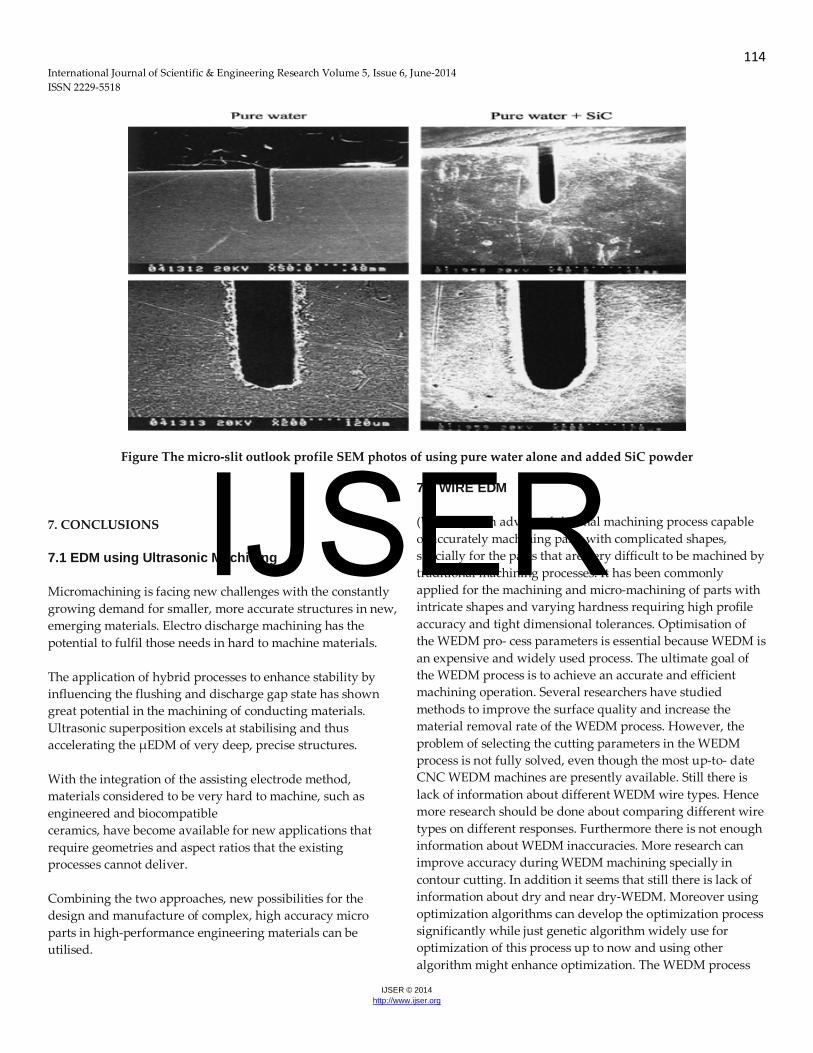
Figure The micro-slit outlook profile SEM photos of using pure water alone and added SiC powder
7. CONCLUSIONS
7.1 EDM using Ultrasonic Machining Micromachining is facing new challenges with the constantly growing demand for smaller, more accurate structures in new, emerging materials. Electro discharge machining has the potential to fulfil those needs in hard to machine materials. The application of hybrid processes to enhance stability by influencing the flushing and discharge gap state has shown great potential in the machining of conducting materials. Ultrasonic superposition excels at stabilising and thus accelerating the μEDM of very deep, precise structures. With the integration of the assisting electrode method, materials considered to be very hard to machine, such as engineered and biocompatible ceramics, have become available for new applications that require geometries and aspect ratios that the existing processes cannot deliver. Combining the two approaches, new possibilities for the design and manufacture of complex, high accuracy micro parts in high-performance engineering materials can be utilised.
7.2 WIRE EDM (WEDM) is an advanced thermal machining process capable of accurately machining parts with complicated shapes, specially for the parts that are very difficult to be machined by traditional machining processes. It has been commonly applied for the machining and micro-machining of parts with intricate shapes and varying hardness requiring high profile accuracy and tight dimensional tolerances. Optimisation of the WEDM pro- cess parameters is essential because WEDM is an expensive and widely used process. The ultimate goal of the WEDM process is to achieve an accurate and efficient machining operation. Several researchers have studied methods to improve the surface quality and increase the material removal rate of the WEDM process. However, the problem of selecting the cutting parameters in the WEDM process is not fully solved, even though the most up-to- date CNC WEDM machines are presently available. Still there is lack of information about different WEDM wire types. Hence more research should be done about comparing different wire types on different responses. Furthermore there is not enough information about WEDM inaccuracies. More research can improve accuracy during WEDM machining specially in contour cutting. In addition it seems that still there is lack of information about dry and near dry-WEDM. Moreover using optimization algorithms can develop the optimization process significantly while just genetic algorithm widely use for optimization of this process up to now and using other algorithm might enhance optimization. The WEDM process
IJSER
115 International Journal of Scientific & Engineering Research Volume 5, Issue 6, June-2014 ISSN 2229-5518
IJSER © 2014 http://www.ijser.org
has to be constantly improved to maintain as a competitive and economical machining operation in the modern tool room manufacturing industries. Finally it seems that more researches can enhance the capabilities of WEDM process significantly to improve the machining productivity, accuracy and efficiency. 7.4 DRY EDM The characteristics of dry EDM are:- (1) Tool electrode wear is negligible for any pulse duration. (2) The processing reaction force is much smaller than in conventional EDM. (3) It is possible to change supplying gas according to different applications. (4) The residual stress is small since the melting resolidification layer is thin. (5) Working gap is narrower than in conventional EDM. (6) The process is possible in vacuum condition as long as there is a gas flow. (7) The machine structure can be made compact since no working basin, fluid tank and fluid circulation system needed. The development of the technique concerns more on to increase the MRR since the MRR is lower compared to conventional machining. 7.5 EDM USING WATER & POWDER ADDITIVES Because of EDM enormous improvement in machining process has been achieved in recent years. The capability of
machining intricate parts and difficult to cut material has made EDM as one of the most popular machining processes. The contribution of EDM to industries such as cutting new hard materials make EDM technology remains indispensable. The review of the research trends in EDM in water and EDM with powder additives is presented. However, many more issues need to be investigated before the method can be formally accepted by the industry.
• The effect of discharge current and pulse duration has been taken into consideration in various research works but variation in pulse interval has not been investigated or it has been taken into consideration in conjunction with pulse duration by way of duty factor.
• Most of the available research works on powder-mixed dielectric have studied the impact of such machining on MRR, surface roughness and TWR etc. with normal polarity. The study of the impact of this method on surface modification has been taken up by very few researchers.
• Less work has been reported using powders of important alloying elements such as manganese, chromium, molybdenum and vanadium in the dielectric medium. Likewise, some of the important die steel materials such as OHNS die steel, molybdenum high speed tool steels and water-hardening die steels (W-series) have not been tried as work materials.
REFERENCES
[1] K.H. Ho, S.T. Newman, State of the art electrical discharge machining (EDM), International Journal of Machine Tools & Manufacture 43 (2003) 1287–1300. [2] S. Singh, S. Maheshwari, P.C. Pandey, Some investigations into the electric discharge machining of hardened tool steel using different electrode materials, Journal of Materials Processing Technology 149 (2004) 272–277. [3] C.J. Luis, I. Puertas, G. Villa, Material removal rate and electrode wear study on the EDM of silicon carbide, Journal of Materials Processing Technology 164–165 (2005) 889–896.
[4] B. Bojorquez, R.T. Marloth, O.S. Es-Said, Formation of a crater in the workpiece on an electrical discharge machine, Engineering Failure Analysis 9 (2002) 93–97. [5] J. Marafona, J.A.G. Chousal, A finite element model of EDM based on the Joule effect, International Journal of Machine Tools & Manufacture 46 (2005) 1–8. [6] H. Ramasawmy, L. Blunt, Effect of EDM process parameters on 3D surface topography, Journal of Materials Processing Technology 148 (2004) 155–164. [7] Rudorff, D.W., 1961 “Spark machining and its development”, Metal Treatment and Drop Forging, 28 (186), 120–124.
IJSER
116 International Journal of Scientific & Engineering Research Volume 5, Issue 6, June-2014 ISSN 2229-5518
IJSER © 2014 http://www.ijser.org
[8] Pandey, P.C.; Shan, H.S. Modern Machining Process. Tata McGraw- Hill Publishing Company Ltd 1999, 84-113. [9] Smith, G.V., 1961, “Spark machining – fundamental and techniques. J Br Inst Radio Eng,22, 409. [10] Luis, C.J., Puertas, I., Villa, G., 2005 “Material removal rate and electrode wear study on the EDM of silicon carbide”, Journal of Materials Processing Technology, 164–165, 889– Vol.9, No.8 MRR Improvement in Sinking Electrical Discharge Machining 733 896. [11] Schumacher, B.M., 2004 “After 60 years of EDM, the discharge process remains still disputed. Journal of Materials Processing Technology”, 149, 376–381. [12] Singh, S., Maheshwari, S., Pandey, P.C., 2004 “Some investigations into the electric discharge machining of hardened tool steel using different electrode materials”, Journal of Materials Processing Technology, 149, 272–277. [13] Bojorquez, B., Marloth, R.T., Es-Said, O.S., 2002 “Formation of a crater in the workpiece on an electrical discharge machine”, Engineering Failure Analysis, 9, 93–97. [14] Marafona, J.; Chousal, A.G., 2006 “A finite element model of EDM based on the Joule effect”, Int. J. Mach. Tools Manuf., 46 (6), 595-602. [15] Kuneida, M., Lauwers, B., Rajurkar, K.P., Schumacher, B.M., 2005 “Advancing EDM through fundamental insight into the process”, Annals of CIRP, 54 (2), 599–622. [16] Altpeter, F., Perez, R., 2004 “Relevant topics in wire electrical discharge machining Control”, Journal of Materials Processing Technology, 149, 1-3, 147-151. [17] Z.N. Guo, T.C. Lee, T.M. Yue, W.S. Lau, A study of ultrasonicaided wire electrical discharge machining, Journal of Materials Processing Technology 63 (1997) 823–828. [18] J.H. Zhang, T.C. Lee, W.S. Lau, X. Ai, Spark erosion with ultrasonic frequency, Journal of Materials Processing Technology 68 (1997) 83–88. [19] J. Zhixin, Z. Jianhua, A. Xing, Ultrasonic vibration pulse electrodischarge machining of holes in engineering
ceramics, Journal of Materials Processing Technology 53 (1995) 811–816. [20] Ogawa Hitoshi, Nogami Teruo, Marimoto Iwao, Study of Micro Machining of Metals by EDM with High Frequency Vibration, Takushima Prefectual Industrial Technology Center, 1999–2001. [21] T.H. Thoe, D.K. Aspinwall, N. Killey, Combined ultrasonic and electrical discharge machining of ceramic coated nickel alloy, Journal of Materials Processing Technology 92–93 (1999) 323–328. [22] Z. Wansheng, W. Zhenlong, D. Shichun, C. Guanxin, W. Hongyu, Ultrasonic and electric discharge machining to deep and small hole on titanium alloy, Journal of Materials Processing Technology 120 (2002) 101–106. [23] Kunieda, M., Lauwers, B., Rajurkar, K. Schumacher, B. (2005). Advancing EDM through Fundamental Insight into the Process. CIRP Annals - Manufacturing Technology, vol. 54, p. 64-87, DOI:10.1016/S0007- 8506(07)60020-1. [24] Liao, Y.S., Chang, T.Y., Chuang, T.J. (2008). An on-line monitoring system for a micro electrical discharge machining (micro-EDM) process. Journal of Micromechanics and Microengineering, vol. 18, no. 3, 035009, DOI:10.1088/0960 1317/18/3/035009. [25] Garn, R., Schubert, A. Zeidler, H. (2011). Analysis of the effect of vibrations on the micro-EDM process at the workpiece surface. Precision Engineering, vol. 35, no. 2, p. 364-368, DOI:10.1016/j. precisioneng.2010.09.015. [26] Abdulkareem, S., Ali Khan, A., Zain, Z. M. (2011) ‘‘Experi- mental Investigation of Machining Parameters on Surface Roughness in Dry and Wet Wire-Electrical Discharge Machining’’ Advanced Materials Research Vols. 264-265 pp. 831-836. [27]. Anand, K. N., (1996): ‘‘Development of process technology in wire-cut operation for improving machining quality’’, Total Quality Management, Vol.7:1, pp. 11-28. [28]. Antar, M.T. ,Soo S.L., Aspinwall, D.K., Jones, D., Perez, R.(2011) ‘‘Productivity and workpiece surface integrity when WEDM aerospace alloys using coated wires’’ Procedia Engineering Vol.19, pp.3 – 8
IJSER

117 International Journal of Scientific & Engineering Research Volume 5, Issue 6, June-2014 ISSN 2229-5518
IJSER © 2014 http://www.ijser.org
[29]. Aspinwall, D.K., Soo, S.L., Berrisford, A.E, Walder, G.(2008). Workpiece surface roughness and integrity after WEDM of Ti–6Al–4V and Inconel 718 using minimum damage generator technology, CIRP Annals – Manufacturing Technology Vol.57:pp. 187–190. [30]. Bamberga,E., Rakwal,D.,( 2 0 0 8 ) ‘Experimental investigation of wire electrical discharge machining of gallium doped germanium’’ journal of materials processing technology. Vol. 197, pp. 419–427. [31]. Benedict, G.F. , (1987) Electrical discharge machining (EDM),Non- Traditional Manufacturing Processes, Marcel Dekker, Inc, New York & Basel, pp. 231–232. [32]. Boopathi, S.(2012) ‘‘Experimental Comparative Study of Near-Dry Wire-Cut Electrical Discharge Machining (WEDM)’’ European Journal of Scientific Research, Vol.75, No.4 , pp. 472-481 [33]. Çaydas, U., Hasçalık, A., Ekici , S., (2009) ‘‘An adaptive neuro fuzzy inference system (ANFIS) model for wire-EDM’’, Expert Systems with Applications Vol.36:pp.6135–6139. [34]. Chen, H.C. , Lin,J.C., Yang,Y.K., Tsai,C.H.,(2007) ‘‘Optimization of wire electrical discharge machining for pure tungsten using a neural network integrated simulated annealing approach’’ Expert Systems with Applications, Vol. 37 pp.7147–7153. [35]. CunShan X., (2012) ‘‘Working Principle and Performance of Wire Electrical Discharge Machining’’ Advanced Materials Research Vol. 507 pp. 180-183. s [36]. Datta, S., Mahapatra S. S., (2010). ‘‘Modeling, simulation and parametric optimization of Wire- EDM process using response surface methodology coupled with grey-Taguchi technique’’ International Journal of Engineering Science and Technology. Vol.2, pp. 162-183. [37]. Dauw, D.F., Albert, L., (1992). ‘‘About the evolution of wire tool performance in wire EDM’’. Annals CIRP. Vol.41 (1), pp. 221-225. [38]. Debabrata, M., Pal., S.K. and Partha, S., (2007). ‘‘Modeling of electrical discharge machining process using back propa- gation neural network and multi-objective optimization us- ing nondominating sorting genetic algorithm-II’’.
Journal of Materials Processing Technology, Vol.186 (1-30), pp.154-162. [39]. Furudate C., and Kunieda, M., (2001), ‘‘Fundamental study on dry-WEDM’’ Journal of the Japan Society for Precision Engineering. Vol. 67, Issue 7, pp. 1180-1184. [40] Z.B. Yu, T. Jun, K. Masanori, Dry electrical discharge machining of cemented carbide, Journal of Materials Processing Technology 149 (2004) 353–357. [41] M. Kunieda, S. Furuoya, N. Taniguchi, Improvement of EDM efficiency by supplying oxygen gas into gap, CIRP Annals Manufacturing Technology 40 (1991) 215–218. [42] M. Kunieda, M. Yoshida, N. Taniguchi, Electrical discharge machining in gas CIRP Annals Manufacturing Technology 46 (1997) 143–146. [43] M. Yoshida, M. Kunieda, Study on mechanism for minute tool electrode wear in dry EDM, Seimitsu Kogaku Kaishi/Journal of the Japan Society for Precision Engineering 65 (1999) 689–693.
[43] Y. Zhanbo, J. Takahashi, N. Nakajima, S. Sano, K. Karato, M.
Kunieda, Feasibility of 3-D surface machining by dry EDM (/ http://www.sodic.co.jptechimgarticle_s02.pdfS Downloaded on May 1 2006). [44] L.Q. Li, W.S. Zhao, Z.L. Wang, B.Q. Kou, L.Y. Li Discussion of electrical discharge machining in gas, The 31st IEEE International Conference on Plasma Science 2004, ICOPS2004, ISBN: 0-7803- 8334-6. [45] Q.H. Zhang, J.H. Zhang, S.F. Ren, Z.W. Niu, X. Ai, A theoretical model of surface roughness in ultrasonic vibration assisted electrical discharge machining in gas, International Journal of Manufacturing Technology and Management 7 (2005) 381–390. [46] A. Curodeau, M. Richard, L. Frohn-Villeneuve, Molds surface finishing with new EDM process in air with thermoplastic composite electrodes, Journal of Materials Processing Technology 149 (2004) 278–283. [47] Q.H. Zhang, R.X. Du, J.H. Zhang, J.Y. Yang, S.F. Ren, The mechanism of ultrasonic vibration improving MRR in UEDM in gas, Materials Science Forum 471–472 (2004) 741–745.
IJSER

118 International Journal of Scientific & Engineering Research Volume 5, Issue 6, June-2014 ISSN 2229-5518
IJSER © 2014 http://www.ijser.org
[48] M. Kunieda, Y. Miyoshi, T. Takaya, N. Nakajima, Y.Z. Bo, M. Yoshida, High speed 3D milling by dry EDM, CIRP Annals Manufacturing Technology 52 (2003) 147–150. [49] M. Kunieda, T. Takaya, S. Nakano, Improvement of dry EDM characteristics using piezoelectric actuator, CIRP Annals Manufacturing Technology 53 (2004) 183–186. [50] F.-L. Zhao, Z.-Z. Lu, H. Wang, Z.-Q. Qian, Research on effecting mechanism of particles in powder-mixed EDM, Dalian Ligong Daxue Xuebao/Journal of Dalian University of Technology 45 (2005) 668–671. [51] P. Pecas, E. Henriques, Influence of silicon powder-mixed dielectric on conventional electrical discharge machining, International Journal of Machine Tools & Manufacture 43 (2003) 1465–1471. [52] Q. Yan Ming, L. You He, Powder-suspension dielectric fluid for EDM, Journal of Materials Processing Technology 52 (1995) 44–54. [53] B.H. Yan, Y.C. Lin, F.Y. Huang, C.H. Wang, Surface modification of SKD 61 during EDM with metal powder in the dielectric, Materials Transactions 42 (2001) 2597–2604. [54] K. Furutani, K. Shiraki, M. Ohta, Deposition of lubricant layer by electrical discharge machining during finishing process, Seimitsu Kogaku Kaishi/Journal of the Japan Society for Precision Engineering 67 (2001) 2042–2047. [55] T. Yih-fong, C. Fu-chen, Investigation into some surface characteristics of electrical discharge machining SKD-11 using powder suspension dielectric oil, Materials Processing Technology 170 (2005) 385–391. [56] M.L. Jeswani, Effect of the addition of graphite powder to kerosene used as the dielectric fluid in electrical discharge machining, Wear 70 (1981) 133–139. [57] B.-H. Yan, S.-L. Chen, Effects of dielectric with suspended aluminum powder on EDM, Journal of the Chinese Society of Mechanical Engineers, Transactions of the Chinese Institute of Engineers, Series C/Chung-Kuo Chi Hsueh Kung Ch’eng Hsuebo Pao 14 (1993) 307–312. [58] W.S. Zhao, Q.G. Meng, Z.L. Wang, The application of research on powder mixed EDM in rough machining,
Journal of Material Processing Technology 129 (2002) 30–33. [59] M.L. Jeswani, Electrical discharge machining in distilled water, Wear 72 (1981) 81–88. [60] S. Tariq Jilani, P.C. Pandey, Experimetnal investigations into the performance of water as dielectric in EDM, International Journal of Machine Tool Design and Research 24 (1984) 31–43. [61] W. Konig, F.-J. Siebers, Influence of the working medium on the removal process in EDM sinking, American Society of Mechanical Engineers, Production Engineering Division (Publication) PED 64 (1993) 649–658. [62] J.-P. Kruth, L. Stevens, L. Froyen, B. Lauwers, Study of the white layer of a surface machined by die-sinking electro-discharge machining, CIRP Annals—Manufacturing Technology 44 (1995) 169–172. [63] S.L. Chen, B.H. Yan, F.Y. Huang, Influence of kerosene and distilled water as dielectric on the electric discharge machining characteristics of Ti-6Al-4V, Journal of Materials Processing Technology 87 (1999) 107–111. IJSER