Embed Size (px)
Citation preview
Seismic analysis of a combined suspension and
cable stayed bridge system
C.C. Spyrakos
Department of Civil Engineering, West Virginia University,
Morgantown WV 26506, USA and Department of Civil
Engineering, National Technical University of Athens, Zografos
15700, Athens, Greece
ABSTRACT
This work presents the experimental and analytical evaluation of the Wheeling suspensionbridge, a historic American landmark and the longest single span suspension system in theworld for many years. The study was funded by the FHWA and the WVDOT to assess thecondition of the structure and determine its response to selected seismic motions in order torecommend proper retrofit measures and possible strengthening of the bridge.
The bridge is one of the few historic suspension bridges still in service in the US. The307 m bridge deck is suspended by two main suspension cables assisted by diagonal staycables. The stay cables are located within the end quarter spans, they pass over the saddles ateach tower and are anchored into the main cable anchorages.
The study includes in-situ testing of the cable system, validation of two- and three-dimensional finite element models to reflect the modal characteristics of the bridge, staticanalysis of the structure for code defined dead and live loads, and several seismic analysesusing AASHTO seismic loads and historic earthquake data. The AASHTO seismic loads weremodified to correspond to 10% probability of being exceeded in 100 years. The historic datawere based on Mercalli intensity local earthquakes recorded in the early eighteenth century.Load rating indicated that none of the structural members are overstressed by the posted liveload. The seismic analysis to AASHTO loads showed little damage that was confined to floorbeams at the east tower. Analysis using historic earthquakes showed localized damage of floorbeams and diagonal floor ties at the east tower and top chords of the stiffening truss at mid-span. The study concludes that the methodology can be applied to a wide range of cablesuspension bridges.
1 Introduction
Since many of the suspension bridges in the US built in the 19th centuty are stillin use today (Ulstrup 1993), it is necessary to evaluate their condition and identifynecessary stiffening and strengthening to bring them up to modern standards ofsafety while still respecting the historic fabric of the bridge. The procedurerequires in-situ testing of the system coupled with analysis.
Transactions on the Built Environment vol 20, © 1996 WIT Press, www.witpress.com, ISSN 1743-3509
340 Earthquake Resistant Engineering Structures
The most frequently used classical theories for static analysis of suspensionbridges are the elastic theory and the deflection theory (Steinman 1929). hiaddition to these an approximate method by Tsein (1949) can also be used to getpractical answers that are sufficiently accurate for design purposes (Ulstrup1993). The major distinction between elastic theory and deflection theory is thatthe deflection theory does not assume that the ordinates of the cable curve remainunaltered upon application of loading (Steinman 1929). The elastic theory issufficiently accurate for shorter spans. However the deflection theory is the mostaccurate and results in more economical and slender bridges. Determining theearthquake response of historic long span suspension structures is always a majorproblem for engineers (Castellani 1987). Research on lateral earthquake responseof suspension bridges (Abdel-Ghaffer 1983), vertical seismic behavior ofsuspension bridges and suspension bridge response to multiple-supportexcitations (Abdel-Ghaffer 1982) give in depth detail about the importance ofearthquake response of suspension bridges. The study on natural frequencies andmodes (West el.al 1984) using a finite element formulation demonstrates thevariation of the frequencies and mode shapes of stiffened suspension bridges.Three dimensional models are usually developed with beam and truss elements tomodel both the superstructure and sub-structure (Wilson 1991; Domanoglu et. al1992; Okamoto 1983).
West Virginia is listed among low seismic risk areas in the United States. ForWest Virginia the AASHTO code assigns an acceleration coefficient A of 0.05. Arecent investigation, however, concluded that earthquake hazards should be ofconcern to the state. The investigation combined geological and historic datafrom regional earthquakes that caused structural damage in West Virginia. Broadareas of the state may have already experienced modified Mercalli scale VIIexcitations during the 1886 Charleston, SC and the New Madrid, MOearthquakes of 1811 and 1812. Similar intensity earthquakes were also felt in thesouthern part of the state during the 1897 Giles VA earthquake. The seismicanalysis of the bridge considers both the AASHTO code assigned accelerationcoefficient as well as intensities based on recent studies (King, McCollach andSpyrakos 1993).
2 Historic background and bridge description
The Wheeling suspension bridge is particularly important in the development ofthe long span wire suspension bridge. When it was opened in 1849 it was thelargest span bridge in the world and ushered in a century long leadership enjoyedby American engineers. As a result, it is one of the most significant antebellumcivil engineering structures in the nation.
The bridge was designed by Charles Ellet, Jr., a leading 19th century civilengineer. The original bridge consisted of a timber deck suspended from wroughtiron suspenders which in turn were carried by the main cables. In the originaldesign there were twelve independent cables arranged according to the Frenchgarland system. In 1854, only four years after its completion, the bridge deck was
Transactions on the Built Environment vol 20, © 1996 WIT Press, www.witpress.com, ISSN 1743-3509
Earthquake Resistant Engineering Structures 341
destroyed and the cables dislodged by a tornado which swept up the Ohio valley.It was quickly rebuilt under the supervision of Ellet.
Later the bridge was strengthened and stiffened by the addition of stay cables.This work was undertaken by Washington Roebling who also gathered the twelvecables into two pairs of cables, one pair on each side. This "Roeblingized" bridgeserved until 1956. In 1956 a major rehabilitation was done in which W24X76floor beams, roadway grating, sidewalk grating, and lateral bracing system wereincorporated in the deck system. The most resent rehabilitation was performed in1983. At that time a neoprene wrapping system was added to the mainsuspension cables, together with miscellaneous structural steel repairs andreplacement of damaged stay cables and hanger rods. Additional work includedinstalling new timber stiffening trusses, cleaning and painting of thesuperstructure, repointing the masonry towers, installing stay-hanger connectorsand tensioning the hangers and stay cables. In 1989, additional repairs wereperformed by the State maintenance department.
The structure carries West Virginia state route 251 as it crosses the mainchannel of Ohio river connecting the city of Wheeling and Wheeling island. Thebridge span is about 307.50 m and carries a 6.10 m roadway.The main suspensioncables support the deck of trusses of the bridge. Each cable is approximately19.10 cm in diameter and consists of about 1650 wires of No. 10 gauge (3.42 mmDiameter) laid in parallel. The cables are protected with a liquid neoprene paintand an elastomeric cable cover. The cables are supported at each tower bysaddles comprised of three cast iron rollers. The cable ends are connected toanchor bars which are embedded into concrete anchorages (Lichtenstein 1992).
Diagonal stay cables comprised of wire ropes of varying diameter from 2.54cm to 4.45 cm are located within the end quarter spans. The stay cables pass overthe saddles at each tower and are anchored into the main cable anchorages.
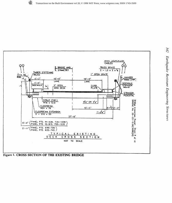
The floor system is suspended from the main cables by pairs of 2.85 cm or3.18 cm diameter hanger rods at each end of the floor beams. The hanger rodsare connected to the main cables by cable bands and attached to the floorbeamswhich consist of rolled steel wide flange W 24X76 sections with a spacing ofapproximately 2.44 m throughout the structure. Figure (1) shows the crosssection of the existing bridge.
The truss verticals are steel rods with a diameter of 3.18 cm, whereas thejunction boxes are cast iron. The trusses are supported by the floorbeamextensions at the panel points. The superstructure supports a 12.70 cm deep opengrid steel grating. A 1.22 m side walk of 2.54 cm deep open grid steel gratingexists along each side of the roadway. The timber truss serves as a guard rail forpedestrians.
The bridge substructure consists of east and west towers constructed with cutstone masonry. The cables at the top of the tower are protected by galvanizedsheet metal housings, while the main cable anchorages are protected by cut stonemasonry anchorage housings.
Transactions on the Built Environment vol 20, © 1996 WIT Press, www.witpress.com, ISSN 1743-3509
JROD
, t
V <L BRIDGE AND TT\ t SYMMETRY 2
L I . TIMBER STIFFENINGT 1 F - /TRUSS 1" OPEN ('̂ \\ m 4"-2- io'-o" lo'-o"— U— ' ̂ • LANE LANE
l\ SIDEWALK «^| 5" OPEN CURB11 ' , „ ' 1 I GRID DECK | PLATE \\\ * * 1 ^
-*feaf̂ '\ STRUT (TYP.) ' , ,'
, \ Wtfi « li.4 | 9U- OR 2V\ \ FLOORBEAM\ W24 K 76 10' -5"\ FLOORBEAM EXTENSION r_?12 - C10 K 25
2T-6"
. . /PANEL PTS. IN-63N. 73N-123NNVPANEL PTS. IS-61S. 75S-123S /
S'-ll'/PANEL PTS. 64N-72N \VPANEL PTS. 62S-74S /
T Y P I C A L E X I S T I N GD E C K C R O S S S E C T I O N
NOT TO SCALE
Figure 1. CROSS SECTION OF THE EXISTING BRIDGE
MAIN jU'jPLNidUNCABLES A
SUSS BRACE V 9- L3 x 2 x V / IIIRATE /
/ IL HANGER••• / / b^ RODS ( TYP "*y/[ SIDEWALK\Jf STRINGER
•*̂ CD CDSI
^ s!' §
en """
o
fc
I
Transactions on the Built Environment vol 20, © 1996 WIT Press, www.witpress.com, ISSN 1743-3509
Earthquake Resistant Engineering Structures 343
The material properties of the system components are:Timber: Dense select structural Douglas fir or Southern pineExtreme fibre in bending (fy) = 13,1 10 KN/rn^Tension parallel to grain (ft) = 7590 KN/m^Compression parallel to grain (fj = 8970 KN/nfHorizontal shear (Q = 586.5Compression perpendicular to grain (f̂ ) = 3 139.50 KN/irfCable WiresYield strength = 6.2 1E5Ultimate strength = 8.55E5Elongation in 25.4 cm length 4%Young's modulus E= 2.0E5 KN/nTStructural SteelSteel members of the bridge conform to ASTM standards.
3 Two and three-dimensional models
Because of the complexity of the structure, a finite element analysis wasemployed to study the behavior of the bridge under static and dynamic loads.Both two and three dimensional models were used to analyze the structure. Inorder to develop a proper FE model and to compare the FE results with elastictheory results two, two-dimensional models were also developed: one withoutstay cables and the other with stay cables, see Fig (2), respectively. In the twodimensional models the stiffening truss is replaced with an equivalent beam.After comparison of the results from the model without stay cables with elastictheory results, a 2-D model with stays and three dimensional models weredeveloped to represent the actual bridge as it exists at the site as of today. Thebridge superstructure, comprised of two main cables, suspenders, stay cables,floor beams, steel grid deck, and a stiffening truss is modeled with threedimensional beam and truss elements. The suspenders and stay cables aremodeled using 3-D truss elements. Beam elements are used to model thestiffening truss, floor beams, and deck. The steel grid deck and side walk weremodeled with beam elements to which equivalent stiffness was assigned tosimulate the stiffness of the system, see Fig (1). End moment releases werespecified at diagonals and verticals to simulate scissors joint conditions.
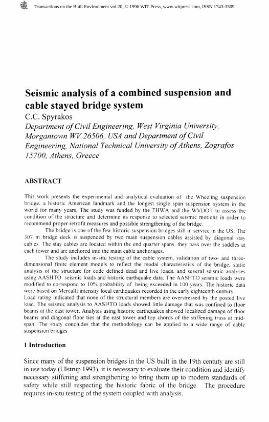
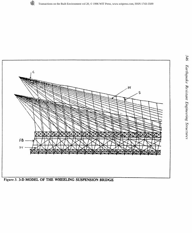
Figure (3) shows the three dimensional finite element model of the westernside of the bridge. At the top of the tower the cable is fixed, since there is noevidence that the rollers function. The stiffening truss is hinged at the supports.The cables in the 3-D model have been placed according to plans of the existingbridge. The suspenders are connected to the channel sections at the bottom oftruss joints and the main cable. The spacing between the suspenders is about2.44 m. Only translational displacements at the top of the suspenders are allowedat the junction of the main cable and suspenders. The ordinates of the cableprofile are measured from available drawings and used in the FE model of thebridge. The eastern side of the bridge is identical to the western side except that
Transactions on the Built Environment vol 20, © 1996 WIT Press, www.witpress.com, ISSN 1743-3509
344 Earthquake Resistant Engineering Structures
Transactions on the Built Environment vol 20, © 1996 WIT Press, www.witpress.com, ISSN 1743-3509
Earthquake Resistant Engineering Structures 345
there are 19 stay cables instead of 17. Also the approach level at the eastern sideis about 9.50 m higher than that of the western side.
4 In-situ evaluation of suspender forces
The main reason for in-situ evaluation was to measure the existing axial forces inthe suspenders using the Axial Load Monitor (ALM), a hand-held forcemeasuring instrument developed at West Virginia University (CFC News) andsubsequently use in finite element analysis.
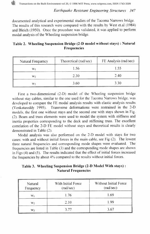
The ALM was used to measure the forces of suspenders that did not intersectwith diagonal stay cables. Table (1) shows the actual load carried inrepresentative suspenders. By measuring the actual load carried by thesuspenders, the forces in the main cables were calculated using equilibriumequations. After calculating the forces in each element (length between twosuspenders) of the main cable, they were applied as initial forces in the FiniteElement (FE) model to represent the forces developed in the main cable causedby the dead load.
Table 1. Measured Suspender forces
Suspender No
37
38
39
Up-Stream Side (KN)
19.20
18.00
16.41
Down-Stream
18.
18.
17.
Side
32
32
64
(KN)
5 Modal analysis
Since the collapse of the Tacoma Narrows Bridge in 1940, considerable amountof research has been conducted to study the dynamic behavior of cablesuspension bridges. Early contributions by Bleich and Steinman adopted ananalytical approach. This 2-D approach is based on several assumptions andempirical rules that could compromise solution accuracy, such as torsionaleffects. Use of finite elements, however, allows accommodation of variouscomplexities of the structure. Comparisons between FE results and analyticalapproaches that yielded comparable results for simple models of cable suspensionbridges have been reported by several researchers ( West et. al 1984; Domanogluet. al. 1992).
In this study the natural frequencies and mode shapes of the stiffenedsuspension bridge are determined using FE analysis. Because of the complexityof the system and consideration of the stiffening effect of the forces in the maincables, the FE procedure was validated through comparison with the well
Transactions on the Built Environment vol 20, © 1996 WIT Press, www.witpress.com, ISSN 1743-3509
5T
DT
§
Cc<-*s
Figure 3. 3-D MODEL OF THE WHEELING SUSPENSION BRIDGE
Transactions on the Built Environment vol 20, © 1996 WIT Press, www.witpress.com, ISSN 1743-3509
Earthquake Resistant Engineering Structures 347
documented analytical and experimental studies of the Tacoma Narrows bridge.The results of this research were compared with the results by West et.al (1984)and Bleich (1950). Once the procedure was validated, it was applied to performmodal analysis of the Wheeling suspension bridge.
Table 2. Wheeling Suspension Bridge (2-D model without stays) : NaturalFrequencies
Natural Frequency
Wj
W2
W]
Theoretical (rad/sec)
1.56
2.30
160
FE Analysis (rad/sec)
1.55
240
330
First a two-dimensional (2-D) model of the Wheeling suspension bridgewithout stay cables, similar to the one used for the Tacoma Narrows bridge, wasdeveloped to compare the FE modal analysis results with elastic analysis results(Venkatareddy 1995). Transverse deformations were restrained in the 2-Dmodels, the first one without stays and the second one with stays shown in Fig.(2). Beam and truss elements were used to model the system with stiffness andinertia properties corresponding to the deck and stiffening truss. The excellentcorrelation of the 2-D FE model without stays and theoretical results is clearlydemonstrated in Table (2).
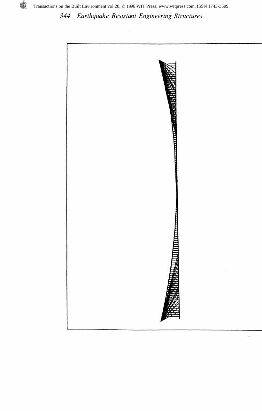
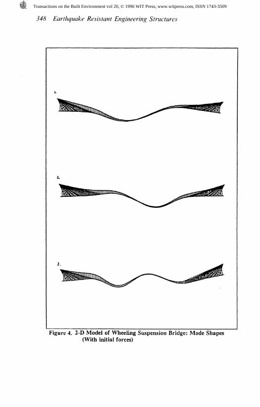
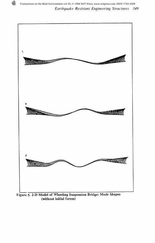
Modal analysis was also performed on the 2-D model with stays for twocases: with and without initial forces in the main cable, see Fig (2). The lowestthree natural frequencies and corresponding mode shapes were evaluated. Thefrequencies are listed in Table (3) and the corresponding mode shapes are shownin Figs (4) and (5). The results indicated that the effect of initial forces increasedthe frequencies by about 4% compared to the results without initial forces.
Table 3. Wheeling Suspension Bridge (2-D Model With stays) :Natural Frequencies
NaturalFrequency
Wi
W]
W]
With Initial Force(rad/sec)
1.76
2.10
3.77
Without Initial(rad/sec)
1.69
1.99
167
Force
Transactions on the Built Environment vol 20, © 1996 WIT Press, www.witpress.com, ISSN 1743-3509
348 Earthquake Resistant Engineering Structures
Figure 4. 2-D Model of Wheeling Suspension Bridge: Mode Shapes(With initial forces)
Transactions on the Built Environment vol 20, © 1996 WIT Press, www.witpress.com, ISSN 1743-3509
Earthquake Resistant Engineering Structures 349
Figure 5. 2-D Model of Wheeling Suspension Bridge: Mode Shapes(without initial forces)
Transactions on the Built Environment vol 20, © 1996 WIT Press, www.witpress.com, ISSN 1743-3509
350 Earthquake Resistant Engineering Structures
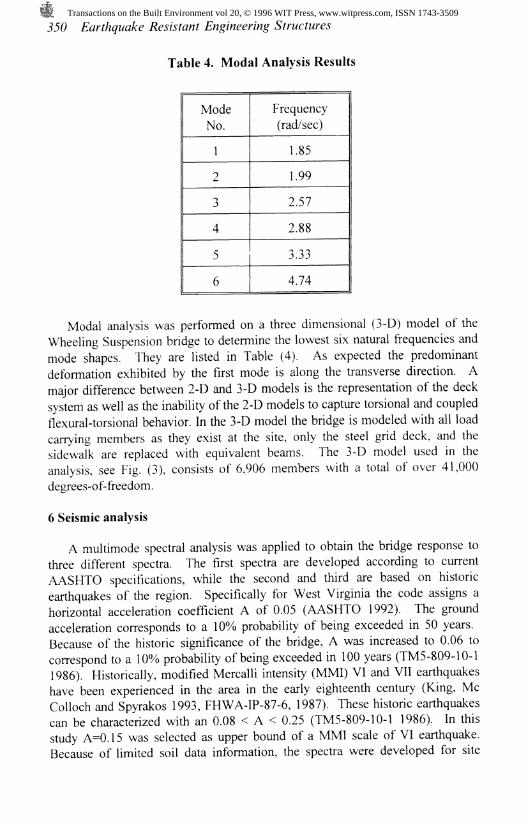
Table 4. Modal Analysis Results
ModeNo.
1
2
3
4
5
6
Frequency(rad/sec)
1.85
1.99
257
2.88
333
4.74
Modal analysis was performed on a three dimensional (3-D) model of theWheeling Suspension bridge to determine the lowest six natural frequencies andmode shapes. They are listed in Table (4). As expected the predominantdeformation exhibited by the first mode is along the transverse direction. Amajor difference between 2-D and 3-D models is the representation of the decksystem as well as the inability of the 2-D models to capture torsional and coupledflexural-torsional behavior. In the 3-D model the bridge is modeled with all loadcarrying members as they exist at the site, only the steel grid deck, and thesidewalk are replaced with equivalent beams. The 3-D model used in theanalysis, see Fig. (3), consists of 6,906 members with a total of over 41,000degrees-of-freedom.
6 Seismic analysis
A multimode spectral analysis was applied to obtain the bridge response tothree different spectra. The first spectra are developed according to currentAASHTO specifications, while the second and third are based on historicearthquakes of the region. Specifically for West Virginia the code assigns ahorizontal acceleration coefficient A of 0.05 (AASHTO 1992). The groundacceleration corresponds to a 10% probability of being exceeded in 50 years.Because of the historic significance of the bridge, A was increased to 0.06 tocorrespond to a 10% probability of being exceeded in 100 years (TM5-809-10-11986). Historically, modified Mercalli intensity (MMI) VI and VII earthquakeshave been experienced in the area in the early eighteenth century (King, MeColloch and Spyrakos 1993, FHWA-IP-87-6, 1987). These historic earthquakescan be characterized with an 0.08 < A < 0.25 (TM5-809-10-1 1986). In thisstudy A=0.15 was selected as upper bound of a MMI scale of VI earthquake.Because of limited soil data information, the spectra were developed for site
Transactions on the Built Environment vol 20, © 1996 WIT Press, www.witpress.com, ISSN 1743-3509
Earthquake Resistant Engineering Structures 351
coefficient S=1.2. Since the AASHTO code Cgm is based on a 5% criticaldamping, it was increased by 25% correspond to 2% of critical damping (TM5-809-10-1 1986). The 2% critical damping is considered more realistic for cablesuspension bridges (FHWA-IP-87-6 1987, Okamoto 1983). A seismic analysiswas also performed for A=0.19, representative of a MMI scale of VII earthquake,to examine the response of this bridge as a representative suspension bridge ofthe several historic bridges built in the Eastern US with historic earthquakeshigher than those predicted for the Wheeling suspension bridge.
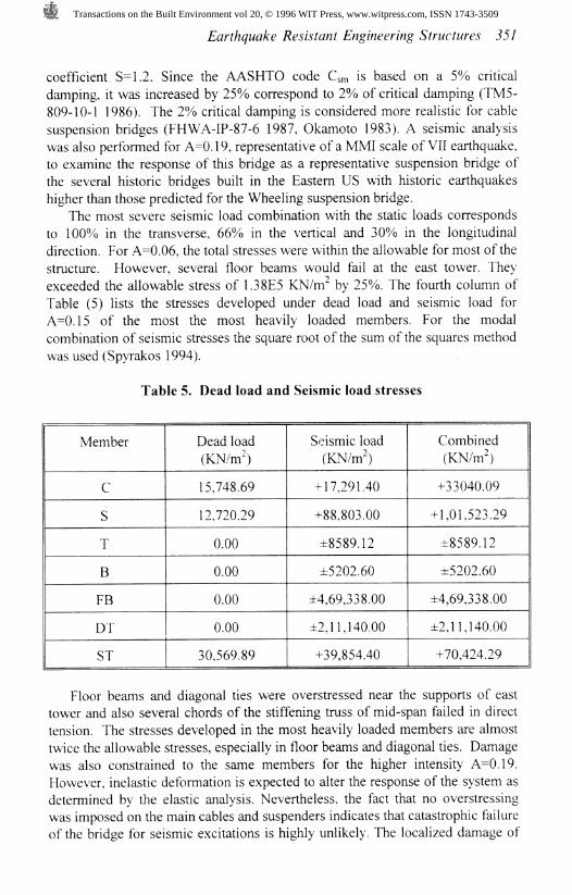
The most severe seismic load combination with the static loads correspondsto 100% in the transverse, 66% in the vertical and 30% in the longitudinaldirection. For A=0.06, the total stresses were within the allowable for most of thestructure. However, several floor beams would fail at the east tower. Theyexceeded the allowable stress of 1.38E5 KN/nf by 25%. The fourth column ofTable (5) lists the stresses developed under dead load and seismic load forA=0.15 of the most the most heavily loaded members. For the modalcombination of seismic stresses the square root of the sum of the squares methodwas used (Spyrakos 1994).
Table 5. Dead load and Seismic load stresses
Member
C
S
T
B
FB
DT
ST
Dead load(KN/m̂ )
15,748.69
12,720.29
0.00
0.00
0.00
0.00
30,569.89
Seismic load(KN/m̂ )
+ 17,291.40
+88,803.00
±8589.12
±5202.60
±4,69,338.00
±2,11,140.00
+39,854.40
Combined(KN/nf)
+33040.09
+1,01,523.29
±8589.12
±5202.60
±4,69,338.00
±2,11,140.00
+70,424.29
Floor beams and diagonal ties were overstressed near the supports of easttower and also several chords of the stiffening truss of mid-span failed in directtension. The stresses developed in the most heavily loaded members are almosttwice the allowable stresses, especially in floor beams and diagonal ties. Damagewas also constrained to the same members for the higher intensity A=0.19.However, inelastic deformation is expected to alter the response of the system asdetermined by the elastic analysis. Nevertheless, the fact that no overstressingwas imposed on the main cables and suspenders indicates that catastrophic failureof the bridge for seismic excitations is highly unlikely. The localized damage of
Transactions on the Built Environment vol 20, © 1996 WIT Press, www.witpress.com, ISSN 1743-3509
352 Earthquake Resistant Engineering Structures
several floor beams and truss members could be avoided through properstiffening and possible installation of damping devices.
7 Conclusions
Seismic analysis showed that the bridge can withstand an earthquake of intensityV Modified Mercalli Intensity (MMI) scale with a peak ground accelerationcoefficient A=0.06 with little damage. For A=0.15 that corresponds to a MMIscale of VI several bridge members at the east tower, i.e., floor beams anddiagonal floor ties, would fail. For A=0.19, an earthquake intensity magnitudecorresponding to a MMI scale of VII, the same members would experiencesevere damage that could lead to localized failure of the bridge deck. Inconclusion, even an intensity MMI scale of VII earthquake will not cause damageof the main cables and the suspenders posing any threat of catastrophic failure tothe bridge. Strengthening of floor beams, diagonal ties at the east tower, and trussmembers at mid-span could mitigate localized damage. The methodology couldbe applied to a wide range of cable suspension bridges.
8 Acknowledgements
The author would like to acknowledge the financial support of the NationalScience Foundation, the West Virginia Department of Transportation, and theFederal Highway Administration.
9 References
1. Abdel-Ghaffer, A.M, Lateral Earthquake Response of Suspension Bridges, J.&rwcf. DzV, /4.SCE, 1983, Vol. 109, No.3. pp. 664-675.
2. Abdel-Ghaffer, A.M., and Rubin, L.I., Suspension Bridge Response toMultiple-Support Excitations. J. Mech. Div. ASCE, 1982, Vol. 108, EM2,pp.419-43 5.
3. Bleich Fredric., C.B. McCullough., Richard Rosecrams., and George S.Vincent. The Mathematical Theory of Vibration in Suspension Bridges.United States Government Printing Office, Washington D.C.,1950
4. Castellani A. Safety Margins of Suspension Bridges Under SeismicConditions. J. SYrwcf. DzV, ASCE, 1987, Vol. 113, No. 7.
5. Domanoglu, A.A., Brownjohn J.M.W., and Severn R.T. Seismic Analysis ofthe Fatih Sultan Mehmat (Second Bosporus) Suspension Bridge. J.Ea/Y/zgwa/ce Engrg. aW&rwcr. DyMamzcc, 1992, Vol. 21, pp. 881-906.
6. FHWA-IP-87-6 Seismic Design and Retrofit Manual for Highway Bridges.Office of Implementation, HRT-10, FHWA, 6400, Georgetown Pike,McLean, Virginia, 1987.
7. Gade. H. R., Harold R. Bosch., and Walter Podolny, Jr., Recent AerodynamicStudies of Long-Span Bridges. J. Struct. Div., ASCE, 1976, Vol. 102,No.S17.
Transactions on the Built Environment vol 20, © 1996 WIT Press, www.witpress.com, ISSN 1743-3509
Earthquake Resistant Engineering Structures 353
8. Gimsing J. Neils. Cable Supported Bridges: Concept and Design. John Wiley&&my, New York, 1982.
9. Kemp, Emory. L. Ellet's Contribution to the Development of SuspensionBridges. Engineering Issues-Journal of Professional Activities, ASCE 99,1973,No.PP3, Paper 9872.
10. Kemp. E. L. Links in Chain, the Development of Suspension Bridges 1801-1870. Published by the Institution of Structural Engineers, London, 1975.
11. Kumarasena, T., Scanlan R.H., and Ehsan F. Wind-Induced Motions of DeerIsle Bridge. J 5Trwcf. DzV, /fSTE, 1991, Vol. 117, No. 1 1.
1 2. Lichtenstein. A. G. & Associates . Final Bridge Inspection Report Langharne,PA, 1992.
13. King, H.M., Me Colloch, J.S., and Spyrakos, C.C. An Earthquake HazardAssessment for West Virginia. Final Report. West Virginia Geological andEconomic Survey, 1993.
14. Okamoto, Shnuzo. Introduction to Earthquake Engineering, Univ. Of TokyoPress, Tokyo, Japan, 1983.
15. Spyrakos, C.C. Assessment of SSI on the Longitudinal Seismic Response ofShort Span Bridges. Engrg. &rwcf, 1990, Vol. 12, pp. 60-66.
16. Spyrakos, C.C. Seismic Behavior of Bridge Piers Including Soil-StructureInteraction. Compwf. & &rwc/., 1992, Vol. 43, No. 2, pp. 373-384.
17. Spyrakos, C.C. Finite Element Modeling in Engineering Practice. Irst print:West Virginia University Press , Morgantown, WV, 1994, 2nd print: Algor
18. Standard Specifications for Highway Bridges, AASHTO. AmericanAssociation of State Highway and Transportation Officials, Washington DC,1992.
19. Steinman, C. A Practical Treatise on Suspension Bridges. 2nd Edition, John%%y <& Sbm\ Inc. New York, 1929.
20. TM5-809-10-1. Technical manual: Seismic Design Guidelines for EssentialBuildings. Department of the Army, the Navy, and the Air force, WashingtonD.C., 1986.
21. Ulstrup C. Carl. Rating and Preliminary Analysis of Suspension Bridges. J.&rwcf. D;V, ASCE, 1991, Vol. 1 19, No. 9.
22. Venkatareddy Ramesh. Validated Analysis of Historic Bridges. M.S. Thesis.,College of Engineering, West Virginia University, Morgantown, WV., 1995.
23. West H. Harry., Joseph E. Suhoski., and Louis F. Geschwindner, Jr., Naturalfrequencies and Modes of Suspension Bridges. J. Struct. Div., ASCE, 1983,Vol. 1 10, No. 10. pp. 2471-2486.
24. Wilson C. John., and Wayne Gravelle. Modelling of a Cable-Stayed Bridgefor Dynamic Analysis. J. Earthquake Engng and Struct. Dynamics, 1991,Vol. 20, pp. 707-721.
Transactions on the Built Environment vol 20, © 1996 WIT Press, www.witpress.com, ISSN 1743-3509