Embed Size (px)
Citation preview

ABSTRACT
ZHU, BEI. Analysis of SIP in UMTS IP Multimedia Subsystem (Under the direction of Professor Arne A. Nilsson)
As a key member of the 3G mobile technologies identified by the ITU (international
Telecommunication Union), UMTS (Universal Mobile Telecommunications System)
represents an evolution in terms of services and data speeds from today's 2G mobile
networks. Third Generation Partnership Project (3GPP) was formed to work on the
technical specification of UMTS.
A UMTS network consists of three interacting domains: Core Network (CN), UMTS
Terrestrial Radio Access Network (UTRAN) and User Equipment (UE). The IP
multimedia subsystem comprises all CN elements for provision of multimedia services.
The Session Initiation Protocol has been chosen by the 3GPP for establishing multimedia
sessions in UMTS Release 5 networks.
The purpose of the research has been to analyze the SIP operation in IP Multimedia
Subsystem of UMTS network from two aspects: bottleneck and delay.
The bottleneck analysis was based on the investigation of the detailed call set up and
release procedures. The signaling flows hit each functional entities (CSCF or HSS) along
the routing chains of signaling traffic several times. Once hit, the functional entity
provides some service and then forwards the traffic on. We counted the hit times of each
functional entity and identified the bottlenecks in different scenarios. We concluded that

which one node would be the bottleneck depends on how the traffic is distributed in the
networks.
We did the delay analysis firstly by describing the SIP signaling traffic with M/M/1
notation. We calculated the delay in each node and gave the waiting time distribution.
Then we assumed the traffic to be M/D/1 and gave the delay in each node. The total delay
in a call set up/release procedure is the summation of the delay of the nodes along the
signaling path. We got that the M/M/1 analysis provides us the upper bound of the
average waiting time of each node, as well as the average delay in the call set up/release
procedure.

ANALYSIS OF SIP IN UMTS
IP MULTIMEDIA SUBSYSTEM
by
BEI ZHU
A thesis submitted to the Graduate Faculty of North Carolina State University
in partial fulfillment of the requirements for the Degree of
Master of Science
COMPUTER ENGINEERING
Raleigh
2003
APPROVED BY:
________________________________ _________________________________
________________________________ Chair of Advisory Committee

DEDICATION
I would like to dedicate this thesis to my husband, my parents and my sister for their
endless love and support. Their care, inspiration and encouragement made it possible for
me to pass the hard time and frustrations. They deserve my sincerest gratitude.
ii

BIOGRAPHY
Bei Zhu was born in Anhui province in China. She received her Bachelor of Engineering
degree in biochemical engineering from Shanghai JiaoTong University in 1992, and her
Master of Engineering degree in bioengineering from Wuxi University of Industry in
1995. She worked in Shanghai Research Center of Biotechnology since then and
continued her studies in the University of Tulsa in Oklahoma in January of 2000. In
January of 2001, she transferred to North Carolina State University to pursue her Master
of Science degree in Computer Engineering. She has finished a number of outstanding
courses and worked on many interesting projects including of Java Programming,
Computer Networks, Database, etc. In the fall of 2001, she joined in Cisco Systems as a
co-op and worked on network testing and solution showcase for the Customer Proof of
Concept Labs. The one-year’s working experience in Cisco Systems has rewarded her
much in the capabilities of both network implementation and team corporation. She is
currently a Cisco Certified Network Associate & Professional and would like to continue
the computer-related research and works after graduation.
iii

ACKNOWLEDGMENTS
I would like to take this opportunity to express my gratitude to all the people who have
helped me on finishing this thesis work.
First, I would like to express my greatest thanks to Professor Arne A. Nilsson, my
advisor, for his guidance and support over the last year. I am deeply indebted to him for
his patience, encouragement, and the countless invaluable suggestions during this project.
A large measure of thanks goes to Dr. Mihail L. Sichitiu since my understanding of the
basic concepts of wireless networks are due to his kind guidance.
I also appreciate Dr. Richard T. Kuehn sincerely for his wise advices on my research
direction when I was totally new to the field of computer engineering.
iv

TABLE OF CONTENTS
LIST OF FIGURES ................................................................................................................................... vi
LIST OF TABLES .................................................................................................................................. vii
CHAPTER 1 INTRODUCTION AND HISTORICAL REVIEW ...................................................... 1
CHAPTER 2 AN INTRODUCTION TO UMTS ARCHITECTURE ................................................ 5 2.1 INTRODUCTION OF GSM/GPRS ARCHITECTURE................................................................... 5 2.2 UMTS ARCHITECTURE OVERVIEW .......................................................................................... 8
2.2.1 3GPP Release99 Architecture ............................................................................................. 9 2.2.1.1 UTRAN Architecture............................................................................................. 9 2.2.1.2 Core Network....................................................................................................... 11
2.2.2 3GPP Release4 Architecture ............................................................................................. 13 2.2.3 3GPP Release4 Architecture ............................................................................................. 15
2.3 IP IP MULTIMEDIA SUBSYSTEM (IMS) ................................................................................... 17
CHAPTER 3 SIP OPERATIONS IN IMS .......................................................................................... 24 3.1 PRE-SETUP PROCEDURES ......................................................................................................... 24
3.1.1 GPRS Attach ..................................................................................................................... 25 3.1.2 PDP Context Activation .................................................................................................... 27 3.1.3 CSCF Discovery................................................................................................................ 28 3.1.4 Service Registration ......................................................................................................... 30
3.2 OVERVIEW OF SIP SESSION FLOW PROCEDURES............................................................... 34 3.2.1 Session Setup Procedures .................................................................................................. 34
3.2.1.1 Origination Procedures ........................................................................................ 35 3.2.1.2 S-CSCF to S-CSCF Procedures ........................................................................... 41 3.2.1.3 Mobile termination procedures ............................................................................ 47 3.2.1.4 Summary of The Session Setup Procedures......................................................... 50
3.2.2 Session Release Procedures............................................................................................... 52
CHAPTER 4 BOTTLENECK ANALYSIS OF IP MULTIMEDIA SUBSYSTEM ........................ 56
CHAPTER 5 DELAY ANALYSIS OF IP MULTIMEDIA SUBSYSTEM...................................... 67 5.1 NOTATION .................................................................................................................................... 67 5.2 DISCUSSION ................................................................................................................................. 68
5.2.1 Analysis based on M/M/1 system...................................................................................... 68 5.2.2 Analysis based on M/D/1 system ...................................................................................... 72
CONCLUSION ......................................................................................................................................... 74
REFERENCES ......................................................................................................................................... 76
APPENDICES ......................................................................................................................................... 78 JAVA Programm A .................................................................................................................... 78 JAVA Programm B .................................................................................................................... 80
v

LIST OF FIGURES
CHAPTER 2
Fig 1. Simplified GSM/GPRS Architecture ........................................................................................... 5
Fig 2. UTRAN Architecture................................................................................................................. 10
Fig 3. 3GPP Release99 Core Network ................................................................................................. 11
Fig 4. Core Network Architecture/UMTS Release 4............................................................................ 13
Fig 5. Vision of 3GPP Release 5 (All IP)............................................................................................. 15
Fig 6. 3GPP R4/5 Reference Logical Architecture .............................................................................. 17
Fig 7. IP Multimedia Subsystem .......................................................................................................... 18
CHAPTER 3
Fig 1. Summary of Procedures Before SIP Sessions............................................................................ 24
Fig 2. Scope of PDP Context................................................................................................................ 27
Fig 3. P-CSCF Discovery Using DHCP and DNS ............................................................................... 29
Fig 4. P-CSCF Discovery Using PDP Context Activation Signaling................................................... 29
Fig 5. Registration Procedure for Un-registered User .......................................................................... 30
Fig 6. Overview of Session Flow Sections........................................................................................... 34
Fig 7. Mobile Origination Procedure- Roaming................................................................................... 37
Fig 8. S-CSCF to S-CSCF Procedure - Different Operators ................................................................ 42
Fig 9. Mobile Termination Procedures – Roaming .............................................................................. 46
Fig 10. Simplified Mobile-to-Mobile Call flow .................................................................................... 51
Fig 11. Mobile Initiated Session Release .............................................................................................. 52
CHAPTER 4
Fig 1. Session Flows in Two Networks................................................................................................ 57
Fig 2. A One-Server Network .............................................................................................................. 62
CHAPTER 5
Fig 1. Queues in the Network............................................................................................................... 71
vi

LIST OF TABLES
CHAPTER 4
Table 1. Description of calls................................................................................................................. 58
Table 2. Routing Chains of the signaling traffic flows......................................................................... 59
Table 3. Traffic distribution and the bottleneck ................................................................................... 61
vii

CHAPTER 1
INTRODUCTION AND HISTORICAL REVIEW In a short span of 20 years, wireless networks have undergone three generations of
evolution [14]. The first generation cellular systems were designed and optimized for
analog transmission of speech signals to and from mobile subscribers. Operated in
circuit-switched mode, these systems offered voice band data transmission. Networks
operating in the 450 and 800 MHz frequency bands used variants of Frequency Division
Multiple Access (FDMA) schemes. Moreover, inter-working between different networks
was rarely implemented. Consequently, a subscriber could not use services on a network
other than the one to which he or she subscribed.
The advent of GSM for the second generation of cellular systems was a huge step
forward. In its original form, GSM in the 900,1800,and 1900 MHz frequency bands uses
a TDMA scheme for the “circuit mode” transmission of the digitized speech and digital
data at up to 9.6kbits/s. The introduction of Subscriber Identity Module (SIM) cards and
the GSM Mobile Application Part (MAP) protocol enabled flawless inter-working
between different networks, allowing subscribers to roam worldwide.
GSM networks are widely deployed throughout the world and garners more than 60% of
the wireless market [10]. Since GSM networks are designed for circuit switched voice
services and offer low data rates, it is not well suited to support packet switched Internet
services. Several enhancements aiming at packet mode communications suitable for
1

Internet –like services are on the way of evolution from 2G to 3G and are normally
considered as 2.5G. These enhancements are,
• GPRS (General Packet Radio Service), which is added to the GSM networks to
efficiently support packet switched services. It supports up to 160kbit/s packet-switched
mobile data alongside circuit-switched telephony. However, it supports only non-real
time packet switched services.
• EDGE (Enhanced Data Rates For GSM Evolution), which supports data rates of up to
384kbits/s.
• GERAN, (GSM/EDGE Radio Access Network), which is a phase 2 of GSM/EDGE
evolution. It offers data rates of up to 1920kbits/s to support packetized voice and real-
time services.
The introduction of the third generation UMTS (Universal Mobile Telecommunication
System), based on wideband Code Division Multiple access (WCDMA) technology, is a
further step towards satisfying the ever increasing demand for data/Internet services. The
best-known new feature of UMTS is higher user bit rates: up to 384 kbps on circuit-
switched connections, and up to 2Mbps on packet-switched connections can be reached
[2]. Higher bit rates facilitate a great variety of services and applications. UMTS services
key attributes include [7]:
• Personalized services;
• Simple to use;
• Location-based services;
• Immediacy of access to information and the ability to act upon it;
2

• Multimedia and multi-session capabilities, especially combining speech with
pictures/video, and transacting based on selecting from offered choices.
UMTS is the ETSI (European Telecommunications Standards Institute) proposal for
International Mobile Telecommunications (IMT) 2000, the international
Telecommunication Union (ITU) initialized program targets at establishing a worldwide
communication system that allows for universal terminal and user mobility. The studies
had been launched since late 1980s by the effort and funding from both universities and
industries. In January 1998 ETSI Special Mobile Group (SMG) selected two radio
technologies for the UMTS Terrestrial Radio Access (UMTS UTRA) air interface:
Wideband CDMA (WCDMA) on the paired frequency bands for Frequency Division
Duplex (FDD) operation, and Time Division CDMA (TDCDMA) for operation with
unpaired band using Time Division Duplex (TDD) mechanism [15]. This decision
formed the basis for the UMTS terrestrial access (UTRA) proposal submitted by ETSI to
the ITU as a candidate IMT2000 radio transmission technology.
In different parts of the world different issues are emphasized and thus countries
including Japan, the United States and Korea, were independently choosing their own 3G
radio access technologies at the same time in the IMT-2000 framework. The 3G
Partnership Project (3GPP) was set up in 1998 to create a single forum for
standardization of a common UTRA specification. This is an unprecedented worldwide
organization that brings together experts from the various regional standardization
bodies. 3GPP partners include: European Telecommunication Standards Institute (ETSI),
3

Association of Radio Industry Business (ARIB)/Japan, CWTS (China Wireless
Telecommunication Standard group)/China, T1 (Standardization Committee T1 –
Telecommunications)/ US, Telecommunication Technology Association (TTA/Korea),
and Telecommunication Technology Association (TTC/Japan) [1]. So the present status
of UMTS standardization is the result of lengthy research carried out by many countries.
At present, the similar effort is being put into the 4G researches.
Target at analysis of the IP multimedia call session control based on SIP signaling
protocol in IP Multimedia Subsystem, we will first introduce how the architecture evolve
from GSM to UMTS to support multimedia, then we will introduce session flow
setup/release procedures based on SIP in IP multimedia subsystem (IMS), subsequently
we will do bottleneck analysis and delay analysis in IMS.
4

CHAPTER 2
AN INTRODUCTION TO UMTS ARCHITECTURE 2.1 Introduction of GSM/GPRS architecture
Since UMTS as proposed by ETSI rather represents an evolution from the second
generation GSM system to the third generation than a completely new system, it is
necessary to introduce the GSM/GPRS architecture first to illustrate the migration from
GSM to UMTS. Below is a simplified GSM/GPRS architecture:
MT
TE
SIM
BTS
BTS
BSC
MSC/VLR
GMSC
HLR/Auc/EIR
SGSN GGSN
A-bis
Gb
A
PSTN
Another MSC
E
NSS
MS Um
GPRS
Internet
TRAU
User traffic and signaling traffic
BSS
Signaling traffic
Fig 1: Simplified GSM/GPRS
• Mobile station (MS):
MS consists of the physical equipment used by a subscri
Equipment (ME) and the Subscriber Identity Module (S
5
Gn
packet Core
Architecture
ber; it comprise
IM). The ME co
Gi
s the Mobile
mprises the

Mobile Termination (MT) which, depending on the application and services, may
support various combinations of Terminal Adapter (TA) and Terminal Equipment (TE)
functional groups.
• BSS (Base Station Subsystem):
The system performs all functions necessary to maintain radio connections to an MS,
coding/decoding of voice, and rate adaptation to/from the wireless network part. It is
viewed by the MSC through the A interface as being the entity responsible for
communicating with Mobile Stations in a certain area. Similarly, in GPRS, the BSS is
viewed by the SGSN through the Gb interface.
A GSM network comprises many BSSs, each may consist of several BTSs controlled
by one Base Station Controller (BSC). A-bis is the interface between BSC and BTS.
1. BTS (Base Transceiver Station): A network component that serves one cell. It
takes care of air interface (Um) signaling, ciphering and speech processing.
2. BSC (Base Station Controller): The central element of the BSS with the functions
for control of one or more BTS.
3. TRAU (Transcoding and Adaptation Unit): The BSS element which takes care of
the speech transcoding., i.e., it is capable of converting speech from one digital
coding format to another and vice versa.
• NSS (Network Subsystem)
The NSS connects the wireless network with standard public networks, performs
handovers between different BSSs, and comprises functions for worldwide localization
6

of users and supports charging, accounting, and roaming of users between different
providers in different countries. It contains following elements:
1. MSC (Mobile Switching Center): The main element of the NSS from the call
control point of view. MSC constitutes the interface between the radio system and
the fixed networks. It performs all necessary functions in order to handle the circuit
switched services to and from the mobile stations.
2. GMSC (Gateway MSC): The element participating in mobility management,
communication management and connections to other networks.
3. HLR (Home Location Register): The central location and management database,
which stores subscriber information (international mobile station identity, user
profile, etc) as well as dynamic location information concerning the current location
area of the MS.
4. VLR (Visitor Location Register): Location and management database associated
with each MSC. It provides a local store for all the variables and functions needed
to handle calls to and from mobile subscribers in the area related to the MSC.
5. Auc (Authentication Center): Manages the authentication and encryption for each
subscriber.
6. EIR (Equipment Identity Register): Keeps track of mobile stations and their
identities in order to prevent the use of stolen equipments.
• GPRS packet Core: provides packet mode data transfer. It requires two additional
nodes:
7
1. SGSN (Serving GPRS Support Node): Responsible for mobility management,
security and authorization functions.
2. GGSN (Gateway GPRS Support Node): The inter-working unit between the GPRS
network and external Packet Data Network (PDN). GGSN is responsible for IP address
management, QoS management and external gateway functions.
Since GSM/GPRS is capable of providing the basic communication service for both
circuit and packet switched traffic, it became the basis of UMTS Core Network, which
we will describe in detail in the chapter.
2.2 UMTS Architecture Overview
A UMTS network consists of three interacting domains: User Equipment (UE), UMTS
Terrestrial Radio Access Network (UTRAN) and Core Network (CN).
The basic UMTS architecture is shown as following [3]. UTRAN is connected to the user
equipment (UE) via the radio interface Uu, and UTRAN communicates with the core
network (CN) via the Iu interface.
Uu
Iu
UE UTRAN CN
• UE (User equipment)
The user equipment consists of two parts: Mobile Equipment (ME) and UMTS
Subscriber Identity Module (USIM)
1. ME: The terminal used for radio communication over the air interface.
8

2. USIM: A smart card that holds the subscriber’s identity and performs a number of
security functions
• UTRAN (UMTS Terrestrial Radio Access Network)
The main task of UTRAN is to create and maintain Radio Access Bearers (RAB) for
communication between UE and CN.
• CN (Core Network)
The core network (CN) contains functions of inter-system handover, gateways to other
networks (fixed or wireless), and network management functions. The goal of 3G CN
is to act as universal core for connecting different radio access and fixed networks.
2.2.1 3GPP Release99 Architecture
The first version of UMTS Specifications, 3GPP R99 presents the new WCDMA based
radio access network, UTRAN, and describes the core network evolved from GSM
network with GPRS.
2.2.1.1 UTRAN Architecture
The basic functional blocks of the UTRAN architecture are the node B and the radio
network controller (RNC). UTRAN is connected to UE via the radio interface Uu, which
is comparable to the Um interface in GSM system, and communicates with the Core
Network via the Iu interface, which is similar with the A interface in GSM. Below is the
URTAN architecture [15].
9

Uu
UE
Iu
Iur
Iub
Iub
Iub
RNS
Node B
Node B
URTAN
Node B
Node B
Iub
Core network
RNCRNC
Radio Network Subsystem (RNS)
Iu
Fig 2. UTRAN Architecture
• Node B: Converts the data flows between the Iub and Uu interfaces, and participates in
radio resource management [14]. It can be said to be roughly equivalent to GSM BTS.
• Radio Network Controller (RNC): The RNC is the service access point for all the
services that the UTRAN provides to the core network. The RNC is roughly equivalent
at a peer level to the GSM BSC. It is responsible for controlling the resources
associated with a number of node Bs, and for negotiating with the core network for
aspects such as bearers and Quality of Service.
10
3GPP UMTS Release '99 architecture describes the new radio interface, Iur, of the
UTRAN. This interface connects two neighboring radio network controllers (RNC)
together and is used for new WCDMA-based function implemented in the RNC. Base
stations (BS) are connected to the RNC via the Iub interface.
2.2.1.2 Core Network
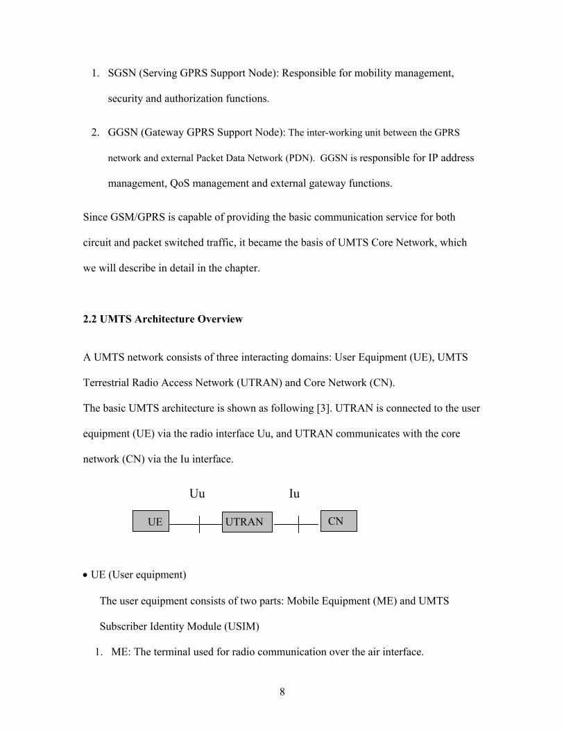
3GPP Release99 minimizes changes needed to the GSM/GPRS network subsystem so
that existing GSM/GPRS network elements can smoothly support both generations. The
UMTS core network has a circuit switched domain (CS-CN) and a packet switched
domain (PS-CN). UTRAN connected with the circuit switched domain via IuCS
interface and packet switched domain via IuPS.
u
Gb
Iu-PS
Iu-CS
Another MSC
E
S
MSC/VLR
HLR/Auc/ EIRGn
GSN IP Backbone
11
GMSC
GSM BSSUTRAN
Gi
GGSN
Other Networks (PSTN,ISDN,etc)
AIP networks
CN
CS-CNPS-CN
User traffic and Signaling traffic Signaling traffic
Fig 3. 3GPP Release99 Core Network
• CS-CN
Circuit Switched domain is evolved from GSM NSS. The CS-CN supports
connectivity to the Public switched Telephone Network (PSTN) and the Integrated
Digital Services Network (ISDN) for circuit switched services. It supports traditional
telephony services such as voice and fax, and also supports enhanced services such as
Short Message Service [10]. The important components of CS-CN are MSC, VLR and
GMSC.
• PS-CN
Packet Switched domain is evolved from IP based GPRS core networks. The PS-CN
supports connectivity to the packet data networks such as the Internet for packet
switched services. The important components of PS-CN are SGSN and GGSN. The
transport network connecting SGSN and GGSN is called IP backbone, which can be
regarded as a private “Intranet” and thus is actually separated from other networks by
firewall functionality [1].
• HLR and Auc
HLR maintains the subscriber profile for both circuit and packet services. Auc supports
authentication functions for both domains. Therefore these components belong to both
domains.
12

While all elements have the same name as that in 2G, they are modified technically for
UMTS operation and services. 3GPP Release99 CN offers interoperability with other 2-
3G networks and allows operators to gracefully evolve their networks to the UMTS
architecture.
2.2.2 3GPP Release4 Architecture
MGW MGW
MSC Server
SGSN GGSN
HSS
IP, Multimedia
GMSC Server
CS-CN
3GPP Release 4 does not change access n
especially the circuit switched domain rem
CS-CN is the separation of the user plane
into an MSC server and a Media Gateway
same manner as the MSC, with a GMSC s
IMS
PS-CN
etwork much
arkably. One
and the contro
(MGW), and
erver and a m
13
PSTN, etc
Signaling traffic Signaling & user traffic
Fig 4.Core Network Architecture/UMTS Release 4AN
but upgraded the core network,
of the most salient features of R4
l plane: MSC/VLR is divided
the GMSC is broken down in the
edia gateway.

• MSC server
The main function of MSC server is connection management, i.e., it handles all the
signaling and controls the media gateway. The MSC server also contains a VLR to
hold the mobile subscriber’s service data.
• Media Gateway
Here the MGW refers specifically to the CS domain entity and thus may be termed as
CS-MGW. It moves the media (e.g. voice) from a circuit switched bearer to an IP bearer,
and may also have additional functions such as echo canceling and transcoding. [8]. We
will describe the Media Gateway in the IMS subsystem later.
The above architecture introduced the separation of the user plane (the bearer for data)
and the control plane (the bearer for signaling and control). Thus two benefits are
basically gained [8]:
1. The media translation makes it possible to use a common IP network for both
packet switched and circuit switched data, this IP network could also be used for
other traffic types at the same time.
2. As one MSC or GMSC server may control several media gateways, the flexibility
and scalability of the architecture is enhanced. In addition, signaling and user
data capacity can be scaled independently.
Another important aspect in 3GPP R4 CN architecture is the addition of IP Multimedia
Subsystem (IMS), which enables PLMN (Public Land Mobile Network) operators to
14

offer their subscribers the multimedia services based on and built upon Internet
applications, services and protocols.
It is noteworthy that the IP multimedia subsystem utilizes the PS domain to transport
multimedia signaling and bearer traffic. It is independent of the CS domain although
some network elements may be common with the CS domain [18]. This means that it is
not necessary to deploy a CS domain in order to support an IP multimedia subsystem
based network.
The IP multimedia subsystem comprises all CN elements for provision of multimedia
services. We will describe these in detail in section 2.3.
2.2.3 3GPP Release5 Architecture:
UTRAN
GERAN
Iu
IP, Multimedia
PSTN,etcISDN
GGSNSGSN
IP/ATM
HSS
Fig 5. Vision of 3GPP Release 5 (All IP
15
IMS
PS-CN
)
In 3GPP R5 the access network experiences more changes and the changes in CN is
minor. Here the main issue is the IP transport in access network. In Release 99, ATM
implements the transmission within the access network due to its strength of QoS
support. As time goes by, IP as a transport technology will contain QoS mechanisms that
provide the support needed for demanding services such as real-time voice and video.
Therefore, in Release 4 of the standards 3GPP is specifying the use of IP as an alternative
to ATM. In Release 5 the evolution continues further and all traffic coming from
UTRAN is IP based and thus the traffic is always packet switched. This will enable
operators to converge their networks from the traditional parallel packet and circuit
switched infrastructure towards an “all-IP” operation. The all-IP network envisages a
future in which there is no need for circuit-switched network elements; all circuit
switched traffic will be re-invented as voice over IP or other real time packet services.
In this phase the main selection criterion for the used radio access technology is to offer
enough bandwidth for the service used and radio technology itself becomes less
important [1]. The future vision is that 3G core network has interfaces for several radio
access technologies, for instance, GSM/EDGE (GERAN), CDMA2000, WCDMA and
Wireless Local Area Network (WLAN), etc.
The reference architecture for 3GPP R4 and R5 provides a detailed view into the UMTS
architecture. They are very similar however in the development of R5 the focus has
shifted to the PS domain, which has been extended with the IMS functionality.
16

Gf Gi
Iu
GiMr
Gi
Ms
Gi
R UuMGW
Gn
Gc
Signalling and Data TransferInterface
SignallingInterface
TE MT UTRAN
Gr
SGSN GGSN
EIR
MGCF
R-SGW *)
MRF
MultimediaIP Networks
PSTN/Legacy/External
Applications &Services *)
Mm
Mw
Legacy mobilesignallingNetwork
Mc
Cx
AlternativeAccess
Network
Mh
CSCF
CSCFMg
T-SGW *)
T-SGW *)
HSS *)
HSS *)
Applications& Services *)
MSC server GMSC server
McMc
D C
SCP
CAP
MGWNb
Nc
Iu
Iu
R-SGW *)Mh
CAPCAP
R UmTE MT
BSS/GERAN
GbA
*) those elements are duplicated for figurelayout purpose only, they belong to the samelogical element in the reference model
Iu
Fig 6. 3GPP R4/5 Reference Logical Architecture [21]
2.3 IP Multimedia Subsystem (IMS)
Within 3GPP groups, service development for VoIP and multimedia over IP have been
termed “IM services”, the IP Multimedia Subsystem in the core network contains the
network elements associated with the IM services. These elements include Call Session
Control Functions (CSCF), Media Gateway Control Function (MGCF) and media
gateways. A conceptual view of the IMS shown below [10]:
17

Fig 7. IP Multimedia Subsystem
• Call Session Control Functions (CSCF)
The call-state control function (CSCF) acts as a call server and handles call signaling, it
supports and controls the multimedia sessions, providing the flexibility to add, modify or
delete bearers used by the user’s service. The protocol that is used for the majority of the
signaling is SIP.
The following functions are handled by CSCF [16]:
Call control function: executes call set up/termination and state/event
management. This is an evolution of the MSC call control function.
Address translation function: Performs address analysis, translation, modification
and mapping.
Serving profiling database: Interacts with HSS to receive and cache user profile.
Incoming call gateway: Acts as an entry point and routes incoming calls.
18

The CSCF can be functionally decomposed to S-CSCF, I-CSCF and P-CSCF. Each will
now be presented.
Proxy - CSCF
The Proxy-CSCF (P-CSCF) is the first contact point in the visited IMS network.
The main functions performed by the P-CSCF are [18]:
Provides authorization of bearer resources and QoS management.
Forward the SIP register request received from the UE to an I-CSCF determined
using the home domain name, as provided by the UE.
Forward SIP messages received from the UE to the SIP server (e.g. S-CSCF)
whose name the P-CSCF has received as a result of the registration procedure.
Forward the SIP request or response to the UE.
Terminate and independently generate SIP transactions in abnormal conditions.
Interrogating - CSCF
Interrogating-CSCF (I-CSCF) is the contact point within an operator’s network for all
connections destined to a subscriber of that network operator, or a roaming user currently
located within that network operator’s service area. There may be multiple I-CSCFs
within an operator’s network. The main functions performed by the I-CSCF are [18]:
Assigning a S-CSCF to a user performing SIP registration. It performs load
balancing between the S-CSCFs with the support of the HSS.
19
Interrogates the HSS during mobile terminated sessions set-up, to obtain the
address of the S-CSCF catering for the mobile, and then forward the SIP request
or response to it.
In performing the above functions the operator may use a Topology Hiding Inter-network
Gateway (THIG) function in the I-CSCF (I-CSCF (THIG)) or other techniques to hide
the configuration, capacity, and topology of the network from the outside. When an I-
CSCF (THIG) is chosen to meet the hiding requirement then for sessions traversing
across different operators domains, the I-CSCF (THIG) may forward the SIP request or
response to another I-CSCF(THIG) allowing the operators to maintain configuration
independence [18].
Serving - CSCF
The Serving Call Session Control Function (S-CSCF) is the node that performs the
session management for the IMS network. There can be several S-CSCFs in the network.
They can be added as needed based on the capabilities of the nodes or the capacity
requirements of the network. The S-CSCF may be chosen differently based on the
services requested or the capabilities of the mobile [18]. The main functions of S-CSCF
include:
Accepts registration requests from UE and makes its information available
through the HSS.
Provide session control for the registered UE 's sessions, i.e., the S-CSCF in the
home network is responsible for all session control. This means that the mobile is
20

not restricted to the capabilities of the visited network as is seen in the current
wireless network.
May accept requests and services them internally or forwards them on.
May terminate and independently generate SIP transactions.
Interact with services platforms for the support of services.
Provide endpoints with service event related information (e.g. notification of
tones/announcement together with location of additional media resources, billing
notification)
• Home Subscriber Server
Home Subscriber Server (HSS) is the centralized subscriber database evolved from the
Home Location Register (HLR). The HSS interfaces with the I-CSCF and the S-CSCF to
provide information about the location of the subscriber and the subscriber’s subscription
information. The HSS is responsible for holding the following user related information
[18]:
User identification, numbering and addressing information.
User security information: Network access control information for authentication
and authorization.
User location information at inter-system level: the HSS supports the user
registration, and stores inter-system location information, etc.
User profile information
21

• Media Gateway and Media Gateway Control Function
In an environment where all of the sessions are between IP capable end user devices,
there would be no need for anything other than the CSCF’s and the HSS. In reality, there
will be a very long transition period to completely eliminate the legacy PSTN and mobile
networks [10].
The IMS supports several nodes for inter-working with legacy networks. These are the
Media Gateway (MGW), the Media Gateway Control Function (MGCF), and the
Transport Signaling Gateway (TSGW.)
Media Gateway Control Function
Controls the call state for media channels in a media gateway. It communicates with the
CSCF and performs protocol conversion between legacy call control protocols and
UMTS call control protocols. For example, the MGCF receives a SIP message from the
CSCF and converts it into appropriate ISUP messages and sends it, via IP, to the
Transport Signaling Gateway.
Media Gateway
Here the Media Gateway refers specifically to the IMS entity and may be termed as IMS-
MGW. Its primary function is to convert media from one format to another. In UMTS
this will predominantly be between Pulse Code Modulation (PCM) in the PSTN and an
IP based vocoder format [10].
22

Transport Signaling Gateway
The signaling end point in the case of interworking with PSTN/legacy networks. It maps
call-related signaling protocols from/to PSTN on an IP bearer and sends it to/from the
MGCF. The T-SGW converts the lower layers of SS7 into IP. The application layer
protocols (for example, ISUP) shall not be affected. It is important to note that it is
always an option to have the MGCF support SS7 and then the T-SGW would not be
required.
23
CHAPTER 3
SIP OPERATIONS IN IMS
Session Initiation Protocol (SIP) is an application-layer control (signaling) protocol for
creating, modifying, and terminating sessions with one or more participants. These
sessions can contain any combination of media (voice, data, video, audio files, anything),
and can be modified at any time to add new parties or to change the nature of the session.
SIP has been chosen as the signaling protocol for establishing multimedia sessions in
UMTS Release5. In this chapter we will describe the operations defined in UMTS IMS
for establishing multimedia sessions.
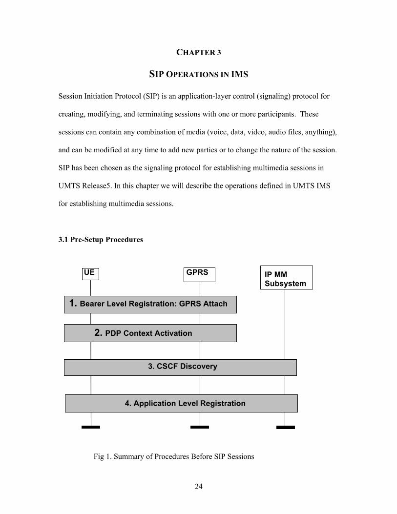
3.1 Pre-Setup Procedures
4. Application Level Registration
3. CSCF Discovery
1. Bearer Level Registration: GPRS Attach
2. PDP Context Activation
GPRS
IP MM Subsystem
UE
Fig 1. Summary of Procedures Before SIP Sessions
24

When a UE is powered on and locked on to the UMTS system, it must take several
critical steps before communicating SIP signaling messages required to establish a data
session.
The key steps are as following:
1. GPRS Attach: to establish Mobility Management Contexts at UE and SGSN.
2. PDP context Activation: to establish GGSN connectivity.
3. CSCF discovery: to obtain the address of P-CSCF, the first contact point within
the IMS subsystem.
4. Service Registration: to send subscriber profile to a S-CSCF in its home network
to obtain IMS services.
In summary, it must create a path toward the proxy CSCF, and performs the service
registration to the Serving CSCF in its home network through the P-CSCF for SIP
services. We will introduce each step in details.
3.1.1 GPRS Attach
As we said in Chapter 2, the IMS uses packet domain of the Core Network to transfer
data and signaling in an efficient manner. A common packet domain Core Network (PS-
CN) is used for both the GERAN and the UTRAN. This common Core Network is
designed to support several Qos levels to allow efficient transfer of non real-time traffic
(e.g. intermittent and bursty data transfers, occasional transmission of large volumes of
data) and real-time traffic (e.g. voice, video). The Serving GPRS Support Node (SGSN)
keeps track of the location of an individual mobile and performs security functions and
25

access control. The Gateway GPRS Support Node (GGSN) provides inter-working with
packet data networks, and is connected with the SGSNs via the PLMN IP backbone.
In order to get access to packet domain service with the UMTS network, a UE shall first
make its presence known to the network by performing a GPRS attach (or called PS
attach). At attach, the SGSN establishes a mobility management context containing
information pertaining to e.g. mobility and security for the UE, and the authentication
procedure is performed in association with the establishment of the mobility management
context.
The UMTS UE sends its International Mobile Subscriber Identifier (IMSI) to the SGSN
in the Attach message. The SGSN uses the IMSI to send a request to the UE’s HSS for
the authentication parameters. The HSS provides the authentication information to the
SGSN, enabling the SGSN to authenticate the subscriber’s IMSI [11,20].
The successful completion of authentication procedure triggers the SGSN to send a
location update to the HSS and this triggers the subscriber’s profile to be downloaded to
the SGSN. This includes information such as the subscribed services, the QoS profile,
any static IP addresses allocated and so on. Then the SGSN completes the Attach
procedure by sending an Attach Complete message to the UE [11].
By GPRS Attach, the location of the mobile is known within the UMTS network, and a
logical association is now established between the UE and the SGSN, this logical
26

connection is maintained as the UE moves within the coverage area controlled by that
SGSN [11]. However this is only the first step toward packet data service. Before the UE
can request IM services, a PDP context must be activated to carry IM subsystem related
signaling.
3.1.2 PDP Context Activation
IP BearerLayer
AccessBearerLayer(eg. UMTSBearer)
LocalUE
SGSN
Scope of PDP Context
IP Bearer Service
RemoteAccessPoint
Gn/Gp
GGSN
RemoteHost
GGSNUE RemoteAP
RemoteHost
Backbone IPNetwork
Figure 2: Scope of PDP Context [22]
A UE subscribed to the UMTS packet domain service is allocated one or more PDP
(Packet Data Protocol) addresses either by the wireless operator statically, or by GGSN
dynamically during the PDP context activation. Each PDP address is an element of a PDP
context. Every PDP context exists independently in one of two states indicating whether
data transfer is enabled for that PDP address or not. The Inactive state means the data
service for a certain PDP address of the UE is not activated, and the PDP context contains
no routing or mapping information to process traffic related to that PDP address. In
Active state, the PDP context for the PDP address in use is activated in the UE, SGSN
27

and GGSN, and the PDP context contains mapping and routing information for
transferring data for that particular PDP address between the UE and the GGSN [17].
So after a UE is attached to an SGSN, it must activate a PDP context to begin the packet
data communication by initiating the PDP Context Activation procedure. This operation
negotiates an active PDP address (in this case, IP address) for the UE and sets up an
association between the UE’s current SGSN and a corresponding GGSN that anchors the
PDP address, thus creates a SGSN-GGSN path for the UE toward the packet data service.
User data is encapsulated with GPRS-specific protocol information and transferred
transparently between the UE and the GGSN.
In the case of a SIP service, the first PDP context must be activated for all SIP related
signaling traffic. This is referred to as primary PDP Context. The UE may also send a
secondary PDP Context Activation, which uses the same PDP address as the Primary
Context with distinctly different QoS requirements. The SGSN chooses the appropriate
GGSN for different contexts and services. The choice of the GGSN by the SGSN is
independent of the radio resource allocations. A mobile may initiate secondary PDP
context and may be connected to more than one GGSN [11].
3.1.3 CSCF Discovery
The P-CSCF is the first contact point in the IMS subsystem for the UE. The discovery of
the IP address of the P-CSCF shall be performed after or as part of a successful activation
of a PDP context for IMS signaling using one of the following mechanisms [18]:
28

1. Use of DHCP to provide the UE with the domain name of a Proxy-CSCF and the
address of a Domain Name Server (DNS) that is capable of resolving the P-CSCF
name. The GGSN acts as a DHCP Relay Agent, relaying DHCP messages
between UE and the DHCP server.
DNS server
1. PDP Context Activation
DHCP serverGGSN UE
3. DNS-Query/Response
2. DHCP-Query/Response 2. DHCP-Relay
Figure 3: P-CSCF Discovery Using DHCP and DNS [18]
2. The UE requests the P-CSCF address from the GGSN when activating the PDP
context. The GGSN sends the P-CSCF address to the UE when accepting the PDP
context activation. Both the P-CSCF address request and the P-CSCF address
shall be sent transparently through the SGSN.
GGSN SGSN UE
1. Activate PDP Context Request
3. Activate PDP Context Accept
1. Create PDP Context Request
3. Create PDP Context Response
2. Get IP address(es) of P-CSCF(s)
Figure 4: P-CSCF Discovery Using PDP Context Activation Signaling [18]
29

After reception of IP address of a P-CSCF the UE may initiate communication towards
the IP Multimedia subsystem..
3.1.4 Service Registration
A UE needs to perform IMS service registration before it can set up a session. Through
a successful registration the UE will be assigned a suitable S-CSCF in its home network
to obtain the IMS services.
P-CSCF HSSI-CSCF
1. Register2. Register
3. Cx-Query
UE
Visited Network Home Network
4. Cx-Query Resp
5. Cx-Select-pull
6. Cx-Select-pull Resp
10. Cx-Pull
11. Cx-Pull Resp
7. Register
13. 200 OK14. 200 OK
15. 200 OK
8. Cx-put
9. Cx-put Resp
S-CSCF
12. Service Control
Fig 5. Registration Procedure for Un-registered User [18]
30

For a user roaming at a visited network, a detailed information flow is shown in Fig 5.
For users located in their home network, the home network shall perform the role of the
visited network element and the home network elements. The procedures are the same
[18]:
1. The UE sends the Register information flow to the P-CSCF. The information includes
the subscriber identity and home networks domain name.
2. Upon receipt of the register information flow, the P-CSCF shall examine the “home
domain name” to discover the entry point to the home network (i.e. the I-CSCF). The
proxy sends the Register information flow to the I-CSCF with the P-CSCF
address/name, P-CSCF network identifier (e.g., domain name of the P-CSCF
network), and subscriber’s identity, etc. The main job of I-CSCF is to query the HSS
and find the location of the S-CSCF.
3. The I-CSCF sends a UMTS proprietary message, Cx-Query information flow to the
HSS with the subscriber’s identity, P-CSCF network identifier.
The HSS then checks whether the user is registered already. The HSS shall indicate
whether the user is allowed to register in that P-CSCF network according to the User
subscription and operator limitations/restrictions if any.
4. Cx-Query Resp is sent from the HSS to the I-CSCF. If the checking in HSS was not
successful the Cx-Query Resp shall reject the registration attempt. Otherwise the
message will contain the S-CSCF name, if it is known by the HSS, or the S-CSCF
capabilities, if it is necessary to select a new S-CSCF.
31
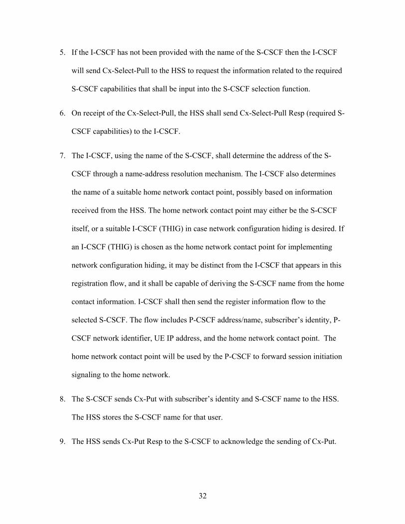
5. If the I-CSCF has not been provided with the name of the S-CSCF then the I-CSCF
will send Cx-Select-Pull to the HSS to request the information related to the required
S-CSCF capabilities that shall be input into the S-CSCF selection function.
6. On receipt of the Cx-Select-Pull, the HSS shall send Cx-Select-Pull Resp (required S-
CSCF capabilities) to the I-CSCF.
7. The I-CSCF, using the name of the S-CSCF, shall determine the address of the S-
CSCF through a name-address resolution mechanism. The I-CSCF also determines
the name of a suitable home network contact point, possibly based on information
received from the HSS. The home network contact point may either be the S-CSCF
itself, or a suitable I-CSCF (THIG) in case network configuration hiding is desired. If
an I-CSCF (THIG) is chosen as the home network contact point for implementing
network configuration hiding, it may be distinct from the I-CSCF that appears in this
registration flow, and it shall be capable of deriving the S-CSCF name from the home
contact information. I-CSCF shall then send the register information flow to the
selected S-CSCF. The flow includes P-CSCF address/name, subscriber’s identity, P-
CSCF network identifier, UE IP address, and the home network contact point. The
home network contact point will be used by the P-CSCF to forward session initiation
signaling to the home network.
8. The S-CSCF sends Cx-Put with subscriber’s identity and S-CSCF name to the HSS.
The HSS stores the S-CSCF name for that user.
9. The HSS sends Cx-Put Resp to the S-CSCF to acknowledge the sending of Cx-Put.
32

10. On receipt of the Cx-Put Resp information flow, the S-CSCF shall send the Cx-Pull
information flow with subscriber’s identity to the HSS in order to be able to
download the relevant information from the user profile to the S-CSCF. The S-CSCF
shall store the P-CSCF address/name, which represents the address/name that the
home network forwards the subsequent terminating session signaling to for the UE
11. The HSS shall return the information flow Cx-Pull Resp with user information to the
S-CSCF. The user information passed from the HSS to the S-CSCF shall include one
or more names/addresses information, which can be used to access the platform(s)
used for service control while the user is registered at this S-CSCF. The S-CSCF shall
store the information for the indicated user. In addition to the names/addresses
information, security information may also be sent for use within the S-CSCF.
12. Based on the filter criteria, the S-CSCF shall send register information to the service
control platform and perform whatever service control procedures are appropriate.
13. The S-CSCF returns the 200 OK information flow with home network contact
information to the I-CSCF. If an I-CSCF is chosen as the home network contact point
for implementing network configuration hiding, the I-CSCF shall encrypt the S-CSCF
address in the home network contact information.
14. The I-CSCF sends information flow 200 OK flow to the P-CSCF. The I-CSCF shall
release all registration information after sending information flow 200 OK.
15. The P-CSCF stores the home network contact information, and sends information
flow 200 OK to the UE.
33

3.2 Overview of SIP Session Flow Procedures
3.2.1 Session Setup Procedures
For an IP Multimedia Subsystem session, the session flow consists three types of
procedures: mobile origination (MO), S-CSCF to S-CSCF, and mobile termination (MT).
A large number of end-to-end session flows are built from combinations of origination,
serving to serving and termination procedures.
The original sequence may be one of the following:
MO#1: Mobile Origination, a mobile roaming at a visit network initiates a session setup;
MO#2: Mobile Origination, a mobile located at home network initiates a session setup;
PSTN-O: PSTN origination;
Fig 6. Overview of Session Flow Sections
One of the MT information flows inserted here
One of the S-CSCF to S-CSCF Information flows inserted here
One of the MO information flows inserted here
UE#S-CSCF#2S-CSCF#1UE#
34

For the termination sequence:
MT#1: Mobile Termination, the called mobile is roaming at a visit network;
MT#2: Mobile Termination, the called mobile is at its home network;
MT#3: The called party is unregistered for IMS services, for ex, users of the legacy
wireless networks.
PSTN-T: PSTN termination;
For Serving-CSCF to Serving CSCF:
S-S#1: The S-CSCF serving the calling party and the S-CSCF serving the called party are
in different networks.
S-S#2: The S-CSCF serving the calling party and the S-CSCF serving the called party are
in the same network.
S-S#3: Session origination with PSTN termination in the same network as the S-CSCF.
S-S#4: Session origination with PSTN termination in a different network to the S-CSCF.
In the thesis we will focus on the call sessions between two IMS registered mobiles and
will not address the interworking of the IMS with the PSTN and legacy wireless
networks.
3.2.1.1 Origination Procedures
As we described in 3.1.3, UE always has a P-CSCF associated with it determined by the
CSCF discovery process. This P-CSCF is located in the same network as the GGSN,
performs resource authorization, and may have additional functions in handling of
emergency sessions. And as the result of the registration procedure, the P-CSCF
35
determines the next hop toward the S-CSCF (possibly through an I-CSCF to hide the
network configuration). Thus a signaling path between the UE and the S-CSCF that is
assigned to perform the service is determined at the time of UE registration and will
remain fixed for the life of the registration. The UE is now capable of initiating a session
setup with the signaling path.
We will present a detailed description of the MO #1 process [18]. The detailed
information flow of MO#2 will not be described here. The procedures are no much
different with MO#1 except the P-CSCF and S-CSCF involved are in the same network.
36

P-CSCF I-CSCF(THIG) S-CSCF
1. Invite (Initial SDP Offer)
2a. Invite (Initial SDP Offer)
2b1. Invite (Initial SDP Offer)
5. Offer Response
9. Response Conf (Opt SDP)
13. Conf Ack (Opt SDP)
11. Response Conf (Opt SDP)
14. Conf Ack (Opt SDP)
19. Reservation Conf
17. Reservation Conf
20. Reservation Conf
16. Reservation Conf
22. Ringing
Originating Home NetworkVisited Network
2b2. Invite (Initial SDP Offer)
4. Invite (Initial SDP Offer)
6a. Offer Response
6b1. Offer Response6b2. Offer Response
8. Offer Response
12. Response Conf (Opt SDP)
15. Conf Ack (Opt SDP)
18. Reservation Conf
21. Reservation Conf
26. 200 OK
31. ACK32. ACK
27. 200 OK
29. 200 OK
23. Ringing24. Ringing
33. ACK
3. Service Control
UE
7. Authorize QoSResources
10. ResourceReservation
25. Alert User28. Approval of QoS
Commit
30. Start Media
TerminatingNetwork
Figure 7: Mobile origination procedure - Roaming [18]
37
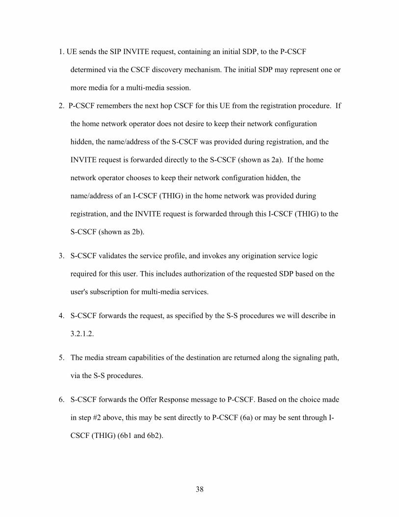
1. UE sends the SIP INVITE request, containing an initial SDP, to the P-CSCF
determined via the CSCF discovery mechanism. The initial SDP may represent one or
more media for a multi-media session.
2. P-CSCF remembers the next hop CSCF for this UE from the registration procedure. If
the home network operator does not desire to keep their network configuration
hidden, the name/address of the S-CSCF was provided during registration, and the
INVITE request is forwarded directly to the S-CSCF (shown as 2a). If the home
network operator chooses to keep their network configuration hidden, the
name/address of an I-CSCF (THIG) in the home network was provided during
registration, and the INVITE request is forwarded through this I-CSCF (THIG) to the
S-CSCF (shown as 2b).
3. S-CSCF validates the service profile, and invokes any origination service logic
required for this user. This includes authorization of the requested SDP based on the
user's subscription for multi-media services.
4. S-CSCF forwards the request, as specified by the S-S procedures we will describe in
3.2.1.2.
5. The media stream capabilities of the destination are returned along the signaling path,
via the S-S procedures.
6. S-CSCF forwards the Offer Response message to P-CSCF. Based on the choice made
in step #2 above, this may be sent directly to P-CSCF (6a) or may be sent through I-
CSCF (THIG) (6b1 and 6b2).
38

7. P-CSCF authorizes the resources necessary for this session. The Authorization-Token
is generated by the PDF (Policy Decision Function), a logical entity of the P-CSCF.
8. The Authorization-Token is included in the Offer Response message. P-CSCF
forwards the message to the originating endpoint
9. UE decides the offered set of media streams for this session, and confirms receipt of
the Offer Response by sending a Response Confirmation to the P-CSCF. The
Response Confirmation may also contain SDP. This may be the same SDP as in the
Offer Response received in Step 8 or a subset. If new media are defined by this SDP,
P-CSCF (PDF) will perform a new authorization as in Step 7 following Step 14. The
originating UE is free to continue to offer new media on this operation or on
subsequent exchanges using the Update method. Each offer/answer exchange will
cause the P-CSCF (PDF) to repeat the Authorization step (Step 7) again.
10. After determining the needed resources in step 8, UE initiates the reservation
procedures for the resources needed for this session.
11. P-CSCF forwards the Response Confirmation to S-CSCF. This may possibly be
routed through the I-CSCF depending on operator configuration of the I-CSCF. Step
11 may be similar to Step 2 depending on whether or not configuration hiding is used.
12. S-CSCF forwards this message to the terminating endpoint, via the S-S procedure.
13-15. The terminating end point responds to the originating end with an
acknowledgement. If Optional SDP is contained in the Response Confirmation, the
Confirmation Acknowledge will also contain an SDP response. If the SDP has
39

changed, the P-CSCF authorizes the resources again. Step 14 may be similar to Step 6
depending on whether or not configuration hiding is used.
16-18. When the resource reservation is completed, UE sends the successful Resource
Reservation message to the terminating endpoint, via the signaling path established
by the INVITE message. The message is sent first to P-CSCF. Step 17 may be similar
to Step 2 depending on whether or not configuration hiding is used.
19-21. The terminating endpoint responds to the originating end when successful
resource reservation has occurred. If the SDP has changed, the P-CSCF performs the
authorization again.
22-24. The Terminating endpoint may generate ringing and it is then forwarded via the
session path to the UE.
25. UE indicates to the originating user that the destination is ringing
26-27. When the destination party answers, the terminating endpoint sends a SIP 200-OK
final response to the originating end, as specified by the termination procedures and
the S-S procedures, to P-CSCF.
28. P-CSCF indicates the resources reserved for this session should now be approved for
use.
29. P-CSCF sends a SIP 200-OK final response to the session originator
30. UE starts the media flow(s) for this session
40

31-33. UE responds to the 200 OK with a SIP ACK message sent along the signalling
path. Step 32 may be similar to Step 2 depending on whether or not configuration
hiding is used.
3.2.1.2 S-CSCF to S-CSCF Procedures
The S-CSCF to S-CSCF procedures specify the signaling path between the serving CSCF
that handles session origination on behalf of the caller, and the serving CSCF that handles
session termination on behalf of the called party.
The S-CSCF handling session origination performs an analysis of the destination address,
and determines whether it is a subscriber of the same network operator or a different
operator. If the analysis of the destination address determined that it belongs to a
subscriber of a different operator, the request is forwarded (optionally through an I-CSCF
(THIG) within the originating operator’s network) to a well-known entry point in the
destination operator’s network, the I-CSCF. The I-CSCF queries the HSS for current
location information. The I-CSCF then forwards the request to the S-CSCF. If the
analysis of the destination address determines that it belongs to a subscriber of the same
operator, the S-CSCF passes the request to a local I-CSCF, who queries the HSS for
current location information. The I-CSCF then forwards the request to the S-CSCF
serving the destination user.
Here we describe the information flow between two S-CSCFs belonging to different
operators [18].
41

S-CSCF#1 I-CSCF#1(THIG) I-CSCF#2 HSS
1. Invite (Initial SDP Offer)
3a. Invite (Initial SDP Offer)
3b1. Invite (Initial SDP Offer)
5. Response
6. Invite (Initial SDP Offer)
9. Offer Response
13. Response Conf (Opt SDP)
17. Conf Ack (Opt SDP)
14. Response Conf (Opt SDP)15. Response Conf (Opt SDP)
18. Conf Ack (Opt SDP)19. Conf Ack (Opt SDP)
25. Reservation Conf
22. Reservation Conf23. Reservation Conf
26. Reservation Conf27. Reservation Conf
21. Reservation Conf
29. Ringing
S-CSCF#2
Originating Home Network Terminating Home NetworkOriginatingNetwork
TerminatingNetwork
3b2. Invite (Initial SDP Offer)
4. Location Query
8. Invite (Initial SDP Offer)
10. Offer Response11a. Offer Response
11b1. Offer Response11b2. Offer Response
12. Offer Response
16. Response Conf (Opt SDP)
20. Conf Ack (Opt SDP)
24. Reservation Conf
28. Reservation Conf
33. 200 OK
39. ACK
37. ACK38. ACK
34. 200 OK35. 200 OK
36. 200 OK
30. Ringing31. Ringing
32. Ringing
40. ACK
2. Service Control
7. Service Control
Fig 8. S-CSCF to S-CSCF Procedure – Different Operators [18]
42

1. The SIP INVITE request is sent from the UE to S-CSCF#1 by the procedures of the
originating flow. This message should contain the initial media description offer in
the SDP.
2. S-CSCF#1 invokes whatever service logic is appropriate for this session attempt.
3. S-CSCF#1 performs an analysis of the destination address, and determines the
network operator to whom the subscriber belongs. For S-S#1, this flow is an inter-
operator message to the I-CSCF entry point for the terminating user. If the originating
operator desires to keep their internal configuration hidden, then S-CSCF#1 forwards
the INVITE request through I-CSCF (THIG)#1 (choice b); otherwise S-CSCF#1
forwards the INVITE request directly to I-CSCF#2, the well-known entry point into
the terminating user’s network (choice a).
4. I-CSCF#2 (at the border of the terminating user’s network) may query the HSS for
current location information.
5. HSS responds with the address of the current Serving-CSCF for the terminating user.
6. I-CSCF#2 forwards the INVITE request to the S-CSCF #2 that will handle the
session termination.
7. S-CSCF#2 invokes whatever service logic is appropriate for this session set up
attempt.
8. The sequence continues with the message flows determined by the termination
procedure.
43

9. The media stream capabilities of the destination are returned along the signaling path,
as per the termination procedure.
10. S-CSCF#2 forwards the SDP to I-CSCF#2
11. I-CSCF#2 forwards the SDP to S-CSCF#1. Based on the choice made in step #3
above, this may be sent directly to S-CSCF#1 (11a) or may be sent through I-CSCF
(THIG)#1 (11b1 and 11b2)
12. S-CSCF#1 forwards the SDP to the originator, as per the originating procedure.
13. The originator decides on the offered set of media streams, confirms receipt of the
Offer Response with a Response Confirmation, and forwards this information to S-
CSCF#1 by the origination procedures. The Response Confirmation may also contain
SDP. This may be the same SDP as in the Offer Response received in Step 12 or a
subset.
14-15. S-CSCF#1 forwards the offered SDP to S-CSCF#2. Step 14 may be similar to
Step 3 depending on whether or not configuration hiding is being used.
16. S-CSCF#2 forwards the offered SDP to the terminating endpoint, via the termination
procedure we will introduce at 3.2.1.3.
17-20 The terminating end point acknowledges the offer with answered SDP and passes
through the session path to the originating end point. Step 19 may be similar to Step
11 depending on whether or not configuration hiding is being used.
44

21-24. Originating endpoint acknowledges successful resource reservation and the
message is forwarded to the terminating end point. Step 22 may be similar to Step 3
depending on whether or not configuration hiding is used.
25-28. Terminating endpoint acknowledges the response and this message is sent to the
originating end point through the established session path. Step 27 may be similar to
Step 11 depending on whether or not configuration hiding is being used.
29-32. Terminating end point then generates ringing and this message is sent to the
originating end point through the established session path. Step 31 may be similar to
Step 11 depending on whether or not configuration hiding is being used.
33-36. Terminating end point then sends 200 OK via the established session path to the
originating end point. Step 35 may be similar to Step 11 depending on whether or not
configuration hiding is being used.
37-40. Originating end point acknowledges the establishment of the session and sends to
the terminating end point via the established session path. Step 38 may be similar to
Step 3 depending on whether or not configuration hiding is being used.
The detailed information flow of S-S#2 will not be described here. The procedures are no
much different except the CSCFs involved (S-CSCF#1&2, I-CSCF#2) are in same
network.
45
P-CSCFI-CSCF(THIG) UE
1. Invite (Initial SDP Offer)
3a. Invite (Initial SDP Offer)
3b1. Invite (Initial SDP Offer)
5. Offer Response
9. Response Conf (Opt SDP)
12. Conf Ack (Opt SDP)
10. Response Conf (Opt SDP)
14. Conf Ack (Opt SDP)
20. Reservation Conf
17. Reservation Conf
21. Reservation Conf
16. Reservation Conf
23. Ringing
Terminating Home Network Visited Network
3b2. Invite (Initial SDP Offer)
4. Invite (Initial SDP Offer)
7a. Offer Response
7b1. Offer Response7b2. Offer Response
8. Offer Response
11. Response Conf (Opt SDP)
15. Conf Ack (Opt SDP)
18. Reservation Conf
22. Reservation Conf
26. 200 OK
31. ACK32. ACK
29. 200 OK30. 200 OK
24. Ringing25. Ringing
33. ACK
S-CSCF
6. Authorize QoSResources
13. ResourceReservation
19. Alert User
27. Approval of QoSCommit 28. Start Media
OriginatingNetwork
2. Service Control
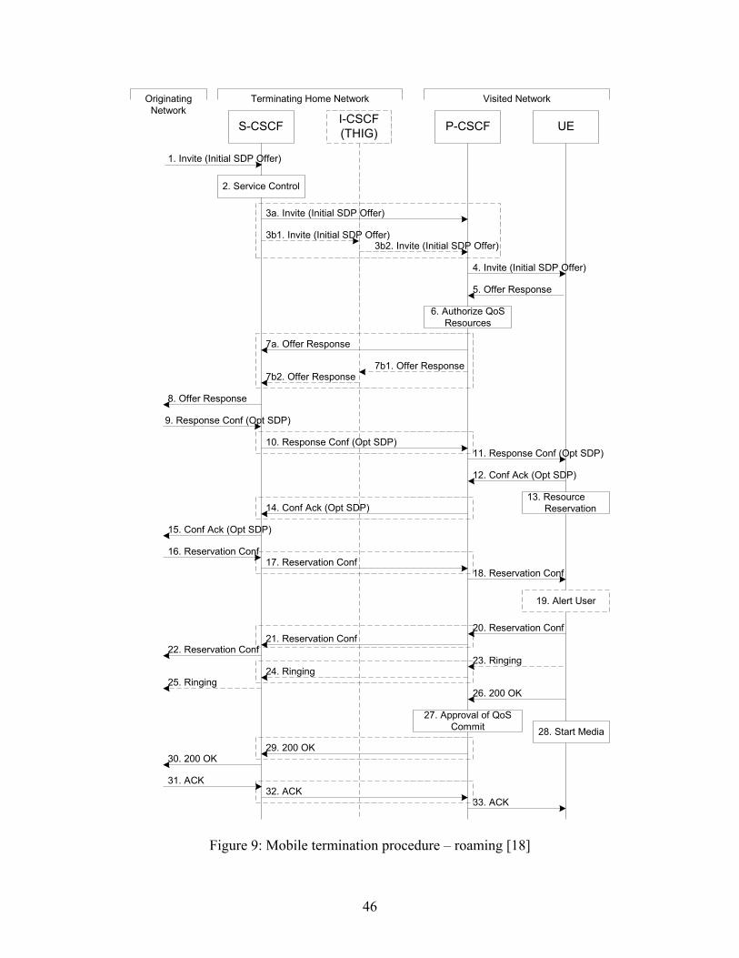
Figure 9: Mobile termination procedure – roaming [18]
46

3.2.1.3 Mobile termination procedures
The session termination procedures specify the signaling path between the Serving CSCF
assigned to perform the session termination service and the UE. Same as what we have
discussed in the origination procedures, this path is determined at the time of UE
registration. However the signaling flows are in the reverse direction of the session-
initiation signaling flows.
Procedure MT#1 is as following [18]:
1. The originating party sends the SIP INVITE request, containing an initial SDP, via
one of the origination procedures, and via one of the Inter-Serving procedures, to the
Serving-CSCF for the terminating users.
2. S-CSCF validates the service profile, and invokes any termination service logic
required for this user. This includes authorization of the requested SDP based on the
user's subscription for multi-media services.
3. S-CSCF remembers (from the registration procedure) the next hop CSCF for this UE.
If the home network operator does not desire to keep their network configuration
hidden, the INVITE request is forwarded directly to the P-CSCF (choice a). If the
home network operator desires to keep their network configuration hidden, the
INVITE request is forwarded through an I-CSCF (THIG) to the P-CSCF (choice b).
4. The PDF generates the Authorization-Token and includes it in the INVITE message.
P-CSCF remembers the UE address from the registration procedure, and forwards the
INVITE to the UE.
47

5. UE determines the subset of the media flows proposed by the originating endpoint
that it supports, and responds with an Offer Response message back to the originator.
The SDP may represent one or more media for a multi-media session. This response
is sent to P-CSCF.
6. P-CSCF authorizes the resources necessary for this session.
7. P-CSCF forwards the Offer Response message to S-CSCF. Based on the choice made
in step #3 above, this may be sent directly to S-CSCF (7a) or may be sent through I-
CSCF (THIG) (7b1 and 7b2).
8. S-CSCF forwards the Offer Response message to the originator, per the S-S
procedure.
9. The originating endpoint sends a Response Confirmation via the S-S procedure, to S-
CSCF. The Response Confirmation may also contain SDP. This may be the same
SDP as in the Offer Response sent in Step 8 or a subset. If new media are defined by
this SDP, a new authorization (as in Step 6) will be done by the P-CSCF (PDF)
following Step 12. The originating UE is free to continue to offer new media on this
operation or on subsequent exchanges using the Update method. Each offer/answer
exchange will cause the P-CSCF (PDF) to repeat the Authorization step (Step 6)
again.
10. S-CSCF forwards the Response Confirmation to P-CSCF. This may possibly be
routed through the I-CSCF depending on operator configuration of the I-CSCF.
11. P-CSCF forwards the Response Confirmation to UE.
48

12. UE responds to the Response Confirmation with an acknowledgement. If Optional
SDP is contained in the Response Confirmation, the Confirmation Ack will also
contain an SDP response. If the SDP has changed, the P-CSCF authorizes the
resources again.
13. UE initiates the reservation procedures for the resources needed for this session.
14-15. P-CSCF forwards the Confirmation Ack to the S-CSCF and then to the originating
end point via session path. Step 14 may be similar to Step 7 depending on whether or
not configuration hiding is used.
16-18. When the originating endpoint has completed its resource reservation, it sends the
successful Resource Reservation message to S-CSCF, via the S-S procedures. The S-
CSCF forwards the message toward the terminating endpoint along the signaling
path. Step 17 may be similar to Step 3 depending on whether or not configuration
hiding is used.
19. UE#2 alerts the destination user of an incoming session set up attempt.
20-22. UE#2 responds to the successful resource reservation towards the originating end
point. Step 21 may be similar to Step 7 depending on whether or not configuration
hiding is used.
23-25. UE may alert the user and wait for an indication from the user before completing
the session set up. If so, it indicates this to the originating party by a provisional
response indicating Ringing. This message is sent to P-CSCF and along the signaling
path to the originating end. Step 24 may be similar to Step 7 depending on whether or
not configuration hiding is used.
49

26. When the destination party answers, the UE sends a SIP 200-OK final response to P-
CSCF.
27. P-CSCF indicates the resources reserved for this session should now be committed.
28. UE starts the media flow(s) for this session
29-30. P-CSCF sends a SIP 200-OK final response along the signaling path back to the
S-CSCF. Step 29 may be similar to Step 7 depending on whether or not configuration
hiding is used.
31-33. The originating party responds to the 200-OK final response with a SIP ACK
message that is sent to S-CSCF via the S-S procedure and forwarded to the
terminating end along the signaling path. Step 32 may be similar to Step 3 depending
on whether or not configuration hiding is used.
The detailed information flow of MT#2 will not be described here. The procedures are no
much different except the P-CSCF and S-CSCF involved are in the same network.
3.2.1.4 Summary of The Session Setup Procedures
If we group the CSCFs according to the UE they are serving but not he networks they are
in, and assume no topology hiding (I-CSCF (THIG)) is utilized so the P-CSCF knows the
address of the S-CSCF, we will get a common session flow between two mobiles as
following no matter how the session is built by different combination of the origination,
S-CSCF to S-CSCF and termination procedures.
50

Figure 10: Simplified Mobile-to-Mobile Call flow
In short, the calling party sends the INVITE message through P-CSCF to the S-CSCF
that is already known by registration. The message is then sent to the I-CSCF, which is
the first contact point of the home network of the called party for incoming network
signaling. Then the message is routed to serving and proxy CSCFs of the called party.
Subsequently the bearer is established and the called user is alerted. When the called user
answers the call the OK message is routed via CSCFs used. Calling party acknowledges
to the called user and call establishment is complete.
In the figure, configuration hiding is not applied. The CSCFs involved may or may not be
in same network, depending on the different scenarios.
51
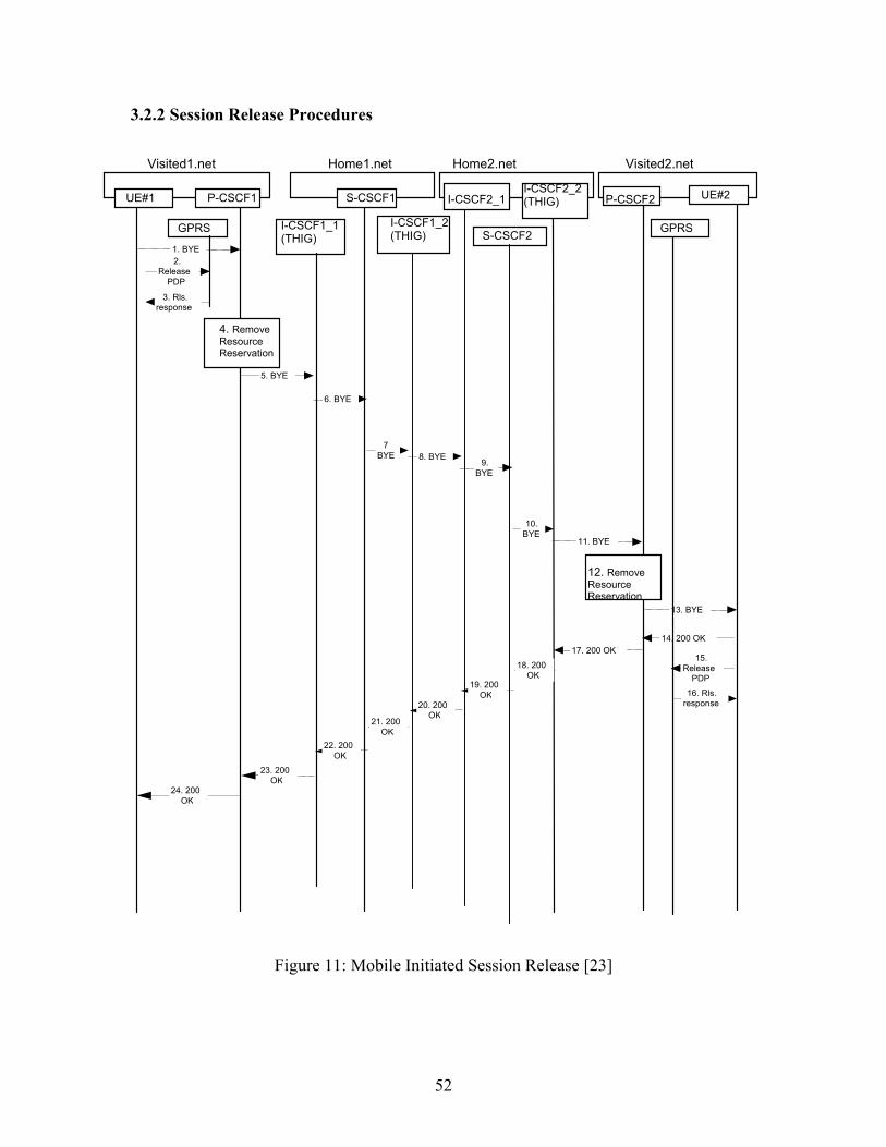
3.2.2 Session Release Procedures
18. 200
OK
24. 200
OK
23. 200
OK
22. 200
OK
21. 200
OK
20. 200
OK
19. 200
OK
11. BY
E
12. Remo evResource
R ervation es
10.BYE
9.BYE
8. BYE
7.BYE
UE#2
6. BYE
17. 200 OK
14. 200 OK
1
re
Releas
6. sp
ePDP
Ro
15.
13. BYE
ls.
nse
5. BYE
4. Remov eResource
eservation R
S-CSCF1
Home1.net
I-CSCF _1 1(THIG)
Home2.net
I-CSCF2_1
S-CSCF
2 I-CSCF2_2 (THIG)
I-CSCF1_2(THIG) GPRS
P-CSCF2
Visited2.net
GPRS
P-CSCF1
lsn
2.1. BYE
3
es
Releas
. Rpo
ePDP
.
r se
UE#
1
Visited1.net
Figure 11: Mobile Initiated Session Release [23]
52

The above flow shows a mobile terminal initiated SIP session release. It is assumed that
the session is active and that the bearer was established directly between the two visited
networks. Here the visited networks could be the Home network in either or both cases,
and the use of I-CSCF (THIG) are optional.
1. One mobile party hangs up, which generates a SIP BYE request from the UE to the P-
CSCF.
2. Steps 2 and 3 may take place before or after Step 1 and in parallel with Step 4. The
UE initiates the release of the bearer PDP context. The GPRS subsystem releases the
PDP context. The IP network resources that had been reserved for the message
receive path to the mobile for this session are now released. This is initiated from the
GGSN. If RSVP was used to allocated resources, then the appropriate release
messages for that protocol would invoked here.
3. The GPRS subsystem responds to the UE.
4. The P-CSCF/PDF removes the authorization for resources that had previously been
issued for this endpoint for this session. This step will also result in a release
indication to the GPRS subsystem to confirm that the IP bearers associated with the
session have been deleted
5. The P-CSCF sends a SIP BYE request to the I-CSCF (THIG) hiding the S-CSCF of
the releasing party.
6. The I-CSCF (THIG) sends a SIP BYE request to the S-CSCF of the releasing party.
7. The SIP BYE request is sent from the S-CSCF to the I-CSCF (THIG).
53

8. The SIP BYE request is sent from the I-CSCF (THIG) to the I-CSCF of the network
of the other party.
9. The SIP BYE request is forwarded from the I-CSCF that was used to determine the
location of S-CSCF of the other party.
10. The SIP BYE request is forwarded to the I-CSCF (THIG).
11. The I-CSCF (THIG) forwards the SIP BYE request to the P-CSCF.
12. The P-CSCF removes the authorization for resources that had previously been issued
for this endpoint for this session. This step also results in a release indication to the
GPRS subsystem to confirm that the IP bearers associated with the UE#2 session
have been deleted.
13. The P-CSCF forwards the SIP BYE request on to the UE.
14. The mobile responds with a 200 OK response, which is sent back to the P-CSCF.
15. Steps 15 and 16 may be done in parallel with step 14. The Mobile initiates the release
of the bearer PDP context.
16. The GPRS subsystem releases the PDP context. The IP network resources that were
reserved for the message receive path to the mobile for this session are now released.
This is initiated from the GGSN. If RSVP was used to allocated resources, then the
appropriate release messages for that protocol would invoked here.
17. The P-CSCF sends the 200 OK to the I-CSCF (THIG).
18. The I-CSCF (THIG) sends the 200 OK to the S-CSCF.
54

19. The S-CSCF of the other party forwards the 200 OK to its selecting I-CSCF.
20. The selecting I-CSCF forwards the 200 OK to the I-CSCF (THIG).
21. The I-CSCF (THIG) forwards the 200 OK to the S-CSCF.
22. The S-CSCF of the releasing party forwards the 200 OK to the I-CSCF (THIG).
23. The I-CSCF (THIG) forwards the 200 OK to the P-CSCF of the releasing party.
24. The P-CSCF of the releasing party forwards the 200 OK to the UE.
55

CHAPTER 4
BOTTLENECK ANALYSIS OF IP MULTIMEDIA SUBSYSTEM
Based on the call setup and release procedures, we know that for each call to be
setup/released, the signalling traffic goes through each involved functional entities
several times. In another word, each functional entity on the routing chain is hit by the
signalling traffic flow several times. Once hit, the CSCF(or HSS) provides some service
and then forwards the traffic on. If we consider the nodes involved as servers, then every
server has a queue formed by different traffic flows waiting to get through. Which server
will be the bottleneck is a critical problem that we are interested in. The analysis of the
bottleneck will help us increase the capacity of the network, and thus increase the
revenue.
We assume no media update occurs, then from the procedures we described in Chapter
3, we will get that in a call set up/release procedure, P-CSCF is hit 11 times, S-CSCF is
hit 11 times, I-CSCF is hit 12 times, and HSS is hit one time.
Assume we have two networks of two different operators. We assume there is one P-
CSCF, S-CSCF and I-CSCF in each network, and they provide the service in a first-
come-first-serve order. Assume the mean service time of P-CSCF is , mean service
time of S-CSCF is , mean service time of I-CSCF is , and mean service time of
HSS is ; Then we will do the bottleneck analysis based on the assumptions.
__Xp
__Xs
__Xi
__Xh
56

We will get all of the possible scenarios within the two networks as follows:
13
V2
H2
H2
V1
H1
H1
P-CSCF2 I-CSCF2 S-CSCF2 HSS2
P-CSCF1 I-CSCF1 S-CSCF1 HSS1
Fig 1. Session Flows in Two Networks
Subscriber of network2
Subscriber of network1
14
12 11 10 9 875
6
43
21
Network2 Network1
H1: non-roaming network1 subscriber
H2: non-roaming network2 subscriber.
V1: network2 subscriber roaming at network1
V2: network1 subscriber roaming at network2.
57

Scenario Description
1 H1→ H2 A non-roaming network1 subscriber calls a non-roaming network2 subscriber.
2 H2→ H1 A non-roaming network2 subscriber calls a non-roaming network1 subscriber.
3 V1→V2 A network2 subscriber roaming at network1 calls a network1 subscriber roaming at network2.
4 V2→V1 A network1 subscriber roaming at network2 calls a network2 subscriber roaming at network1.
5 H1→ V2
A non-roaming network1 subscriber calls a network1 subscriber roaming at network2.
6 V2→ H1
A network1 subscriber roaming at network2 calls a non-roaming network1 subscriber.
7 V1 →H2 A network2 subscriber roaming at network1 calls a non-roaming
network2 subscriber
8 H2 →V1 A non-roaming network2 subscriber calls a network2 subscriber roaming at network1.
9 H1→V1 A non-roaming network1 subscriber calls a network2 subscriber
roaming at network1.
10 V1→H1
A network2 subscriber roaming at network1 calls a non-roaming network1 subscriber.
11 H2→V2
A non-roaming network2 subscriber calls a network1 subscriber roaming at network2.
12 V2→H2
A network1 subscriber roaming at network2 calls a non-roaming network2 subscriber.
13 H1↔H1 The non-roaming network1 subscribers call each other.
14 H2↔H2
The non-roaming network2 subscribers call each other.
Table 1. Description of calls
58

Scenario Routing Chain
1 H1→ H2 P-CSCF1↔S-CSCF1↔I-CSCF2↔HSS2↔S-CSCF2↔P-CSCF2
2 H2→ H1 P-CSCF2↔S-CSCF2↔I-CSCF1↔HSS1↔S-CSCF1↔P-CSCF1
3 V1→V2 P-CSCF1↔S-CSCF2↔I-CSCF1↔HSS1↔S-CSCF1↔P-CSCF2
4 V2→V1 P-CSCF2↔S-CSCF1↔I-CSCF2↔HSS2↔S-CSCF2↔P-CSCF1
5 H1→ V2 P-CSCF1↔S-CSCF1↔I-CSCF1↔HSS1↔S-CSCF1↔P-CSCF2
6 V2→ H1 P-CSCF2↔S-CSCF1↔I-CSCF1↔HSS1↔S-CSCF1↔P-CSCF1
7 V1 →H2 P-CSCF1↔S-CSCF2↔I-CSCF2↔HSS2↔S-CSCF2↔P-CSCF2
8 H2 →V1 P-CSCF2↔S-CSCF2↔I-CSCF2↔HSS2↔S-CSCF2↔P-CSCF1
9 H1→V1 P-CSCF1↔S-CSCF1↔I-CSCF2↔HSS2↔S-CSCF2↔P-CSCF1
10 V1→H1 P-CSCF1↔S-CSCF2↔I-CSCF1↔HSS1↔S-CSCF1↔P-CSCF1
11 H2→V2 P-CSCF2↔S-CSCF2↔I-CSCF1↔HSS1↔S-CSCF1↔P-CSCF2
12 V2→H2 P-CSCF2↔S-CSCF1↔I-CSCF2↔HSS2↔S-CSCF2↔P-CSCF2
13 H1↔H1 P-CSCF1↔S-CSCF1↔I-CSCF1↔HSS1↔S-CSCF1↔P-CSCF1
14 H2↔H2 P-CSCF2↔S-CSCF2↔I-CSCF2↔HSS2↔S-CSCF2↔P-CSCF2
Table 2. Routing Chains of the signaling traffic flows
We have got that for one call setup/release procedure, each P-CSCF and S-CSCF
involved is hit 11 times, each I-CSCF involved is hit 12 times;
Assume the total traffic load is λ (calls/time unit), traffic load for each scenario is λi, and
λ=Σλi,
59

Then we will have the total hits of each node:
P-CSCF1:
Λ 1= (λ1+ λ2+λ3+λ4+λ5+λ6+λ7+λ8) × 11+ (λ9+λ10+λ13) × 22;
P-CSCF2:
Λ 2= (λ1+ λ2+λ3+λ4+λ5+λ6+λ7+λ8) × 11 +(λ11+λ12+λ14) × 22;
S-CSCF1:
Λ 3= (λ1+ λ2+λ3+λ4+λ9+λ10+λ11+λ12) × 11+ (λ5+λ6+λ13) × 22;
S-CSCF2:
Λ 4= (λ1+ λ2+λ3+λ4+λ9+λ10+λ11+λ12) × 11+ (λ7+λ8+λ14) × 22;
I-CSCF1:
Λ 5= (λ2+λ3+λ5+λ6+λ10+λ11+λ13) × 12;
I-CSCF2:
Λ 6= (λ1+λ4+λ5+λ7+λ8+λ9+λ12+λ14) × 12;
HSS1:
Λ 7=(λ2+λ3+λ5+λ6+λ10+λ11+λ13);
HSS2:
Λ 8==(λ1+λ4+λ7+λ8+λ9+λ12+λ14);
And we will have the utilization of each entity:
P-CSCF1: ρ p = Λ 1× , __Xp
P-CSCF2: ρ p = Λ 2× , __Xp
S-CSCF1: ρ s = Λ 3× , __Xs
60

S-CSCF1: ρ s = Λ 4× , __Xs
I-CSCF1: ρ i = Λ 5× , __Xi
I-CSCF2: ρ i = Λ 6 × , __Xi
HSS1: ρ h = Λ 7× , __Xh
HSS2: ρ h = Λ 8× , __Xh
If we assume = = = , we will get the bottleneck if we know the traffic
load of each scenario. The program calculating the bottleneck in this two-networks
system is attached as appendix A at the end of the thesis. We get different node to be
the bottleneck in different situations, and here are some examples:
__Xp
__Xs
__Xi
__Xh
1 2 3 4 5 6 λ1/λ 0.2 0.1 0.05 0.05 0.1 0.1 λ2/λ 0.2 0.1 0.05 0.05 0.1 0.1 λ3/λ 0.05 0.05 0.05 0.05 0.05 0.05 λ4/λ 0.05 0.05 0.05 0.05 0.05 0.05 λ5/λ 0.05 0.05 0.15 0.05 0.15 0.05 λ6/λ 0.05 0.05 0.15 0.05 0.15 0.05 λ7/λ 0.05 0.05 0.05 0.15 0.05 0.05 λ8/λ 0.05 0.05 0.05 0.15 0.05 0.05 λ9/λ 0.03 0.03 0.05 0.05 0.05 0.15 λ10/λ 0.03 0.03 0.05 0.05 0.05 0.15 λ11/λ 0.02 0.12 0.05 0.05 0.05 0.05 λ12/λ 0.02 0.12 0.05 0.05 0.05 0.05 λ13/λ 0.1 0.1 0.1 0.1 0.05 0.05 λ14/λ 0.1 0.1 0.1 0.1 0.05 0.05
Bottleneck P-CSCF1 P-CSCF2 S-CSCF1 S-CSCF2 S-CSCF1 P-CSCF1
Table 3. Traffic distribution and the bottleneck
61

We find that which one node will be the bottleneck depends on how the traffic is
distributed in the networks. For example, when the traffic between non-roaming
network1 subscribers and network1 visitors becomes heavier, P-CSCF1 is the bottleneck
(situation 6), however if the traffic between non-roaming network2 subscribers and
network2 visitors becomes heavier, P-CSCF2 is the bottleneck (situation2). If we
increase the traffic load between non-roaming network1 subscribers and roaming
network1 subscribers, S-CSCF1 is the bottleneck (situation5), etc. And since there can be
infinite possibilities of traffic distributions, theoretically each node may be the bottleneck
in certain situations.
Now we pick one of the networks and take a look at what is happening in any one given
network:
P-CSCF S-CSCF I-CSCF HSS
Fig 2. A One-Server Network
Because of the nature of “home control of service”, so the CSCFs in a given network
must be serving in one of the following scenarios. In each scenario, the CSCFs of this
network involved are listed, and functional entities from other networks are omitted
(represented by “…”).
1. A subscriber located at home service area
a. For it to be origination: …↔P-CSCF↔S-CSCF↔…
b. For it to be termination: …↔I-CSCF↔HSS↔S-CSCF↔P-CSCF↔...
62

2. A subscriber roaming at a visited network
a. For it to be origination: …↔S-CSCF↔…
b. For it to be termination: …… ↔I-CSCF↔HSS↔S-CSCF↔…
3. Not a subscriber but roaming at its service area (visitor)
a. For it to be origination: …↔P-CSCF↔…
b. For it to be termination: …… ↔P-CSCF↔…
Assume the total traffic load in this network is λ calls/time unit, and assume the
percentage of the load for each scenario is as follows:
1a 1b 2a 2b 3a 3b
A1% A2% B1% B2% C1% C2%
Then we can get the utilization of each node:
P-CSCF: ρ p = (A1+A2+C1+C2)% × λ× 11×__Xp ;
S-CSCF: ρ s = (A1+A2+B1+B2)% × λ× 11×__Xs ;
I-CSCF: ρ i = (A2+B2)% λ× 12× ×__Xi ;
HSS: ρ h = (A2+B2)% × λ× ; __Xh
If we assume the mean service times are the same, then whether the utilization of P-
CSCF or S-CSCF in a given network is bigger depends on the value of (B1+B2) and
(C1+C2). If the traffic to and from roaming subscribers is heavier, then S-CSCF is
bottleneck, if traffic to and from visitors is heavier, then P-CSCF is bottleneck. (The
63

program calculating the bottleneck in the network and the waiting time of each server can
be found in appendix B)
Based on the analysis above, we can have some discussions on how to improve the
capacity of the network. Here is a simple case study:
Assume in a network the current traffic load is λ=10calls/second, the mean service time
of P-CSCF, S-CSCF and I-CSCF are same: = = =0.01s; __Xp
__Xs
__Xi
Assume the traffic distribution in the network is normally as follows:
1a 1b 2a 2b 3a 3b
10% 10% 25% 25% 15% 15%
P-CSCF: ρ p = (10+10+15+15)% × λ× 11×__Xp =0.55;
S-CSCF: ρ s = (10+10+25+25)% × λ× 11×__Xs =0.77;
I-CSCF: ρ i = (10+25)% × λ 12× ×__Xi =0.42;
HSS: ρ h =(10+25)% λ× =0.035; ×__Xh
We get that the S-CSCF is the bottleneck. If we multiply the traffic load by a factor α1,
then we will get the maximum throughput of the network when the utilization of S-CSCF
reaches 1.
64

When α=1.3, ρ s = (10+10+25+25)%λ × α1 × 11×__Xs =1, thus the maximum throughput
of the network (capacity) is 13calls/second. If we add another S-CSCF server in the
network and have the load balanced between the two S-CSCFs, then the mean service
time of the S-CSCF will be half of the original service time, i.e., ’= /2. Then the
utilization of each node will be:
__Xs
__Xs
P-CSCF: ρ p = (10+10+15+15)% × λ× 11×__Xp =0.55;
S-CSCF: ρ s = (10+10+25+25)% × λ× 11×__Xs ’=0.385;
I-CSCF: ρ i = (A2+B2)% λ× 12× ×__Xi =0.42;
HSS: ρ h =(10+25)% λ× =0.035; ×__Xh
Now the network throughput will be decided by P-CSCF rather than S-CSCF. If we
multiply the traffic load by the factor α2, we will get the capacity of the network when
the utilization of P-CSCF reaches 1.
When α2=1.82, ρ p = (10+10+25+25)%λ × α1 × 11×__Xs =1, thus the capacity of the
network is 18.2calls/second.
So the extra throughput equals (18.20-13) calls/second=5.2calls/second. And the capacity
of the network is increased by (5.20/13) × 100%=40%. This means that the revenue will
be increased by 40% due to the extra throughput.
65

If we know the price of a S-CSCF, we will be able to calculate how much more revenue
we will get by adding a server at the bottleneck. For example, if the price of an S-CSCF
is 5% of the revenue, then the increased revenue will be (40%-5%)=35%
66

CHAPTER 5
DELAY ANALYSIS OF IP MULTIMEDIA SUBSYSTEM
Based on the previous chapter, we are able to identify the bottleneck in the IP
Multemedia Subsystem if we know the traffic distribution. Subsequently we will do the
delay analysis. Consider a system that has a capacity C, the maximum rate at which it can
perform work. Assume that R represents the average rate at which work is demanded for
this system. If R<C then the system can handle the demands placed upon it, whereas if
R>C then the system capacity is insufficient and the unpleasant effects of satuation will
be experienced. However even when R<C we will still experience a different set of
unpleasantness that come about because of the irregularity of the demands. Suppose a call
request approaches a server which is busy serving another request, and assume the server
provides service in a first-come-first served order, then obviously the call cannot obtain
service at once and must wait in a queue until the server finishes the service for the
previous calls. The characterization of the wating time in the queue, i.e., the delay, is
another critical aspect for the cost of the network
5.1 Notation
The delay analysis is based on some of the well known random processes that form the
foundation for the queueing theories, like Marchov, Birth-Death, and Poisson Processes,
etc [25]. Here we introduce the notaion required for the statement of results in this
chapter.
67

N(t): Number of customers in system at time t, the corresponding limiting random
variable(after the system has been operating infinitely long) for a stable queue is N
x : service time
x : the mean service time,
t: interarrival time
rk : the equilibrium probability that an arriving customer finds k in the system upon his
arrival
pk : P[N=k], the long-run probability of there being k customers in the system.
d k : the equilibrium probability that a departure leaves k customers in the system.
λk: birth rate, i.e., the customer arrival rate when the system contains k customers.
: death rate, i.e., the customer departure rate when the population is of size k. µk
W : mean of the waiting time.
W(y) : probability distribution function (PDF) of waiting time.
5.2 Discussion
5.2.1. Analysis based on M/M/1 system
If we assume the traffic in the IP Multimedia System is characterized by Poisson arrivals
and exponentially distributed service times, we may use M/M/1 queue for the delay
analysis.
68

M/M/1 queue is the simplest queueing system characterized by Poisson arrivals and unit
step changes (single service completions and single arrivals). It may be described by
selecting the birth-death coefficients as follows:
= λkλ =µk
µ k=1,2,3,…..
In this case, the average interarrival time is: t =λ1
and the average service time is: x =µ1
In a M/M/1 system, = = d , the distribution is given by: r k pk k
= (pk p0 µλ
)k (5.1)
=(1 - p0 µλ
) (5.2)
and thus: =(1-pk
ρ ) ρ k (5.3)
ρ =µλ
= λ x (5.4)
Here ρ gives the fraction of time that the single server is busy and is also equal to the
ratio of the rate at which work arrives to the system divided by the capacity of the system
to do the work, namely, utilization of the network[25].
The average number in the system is given by
69
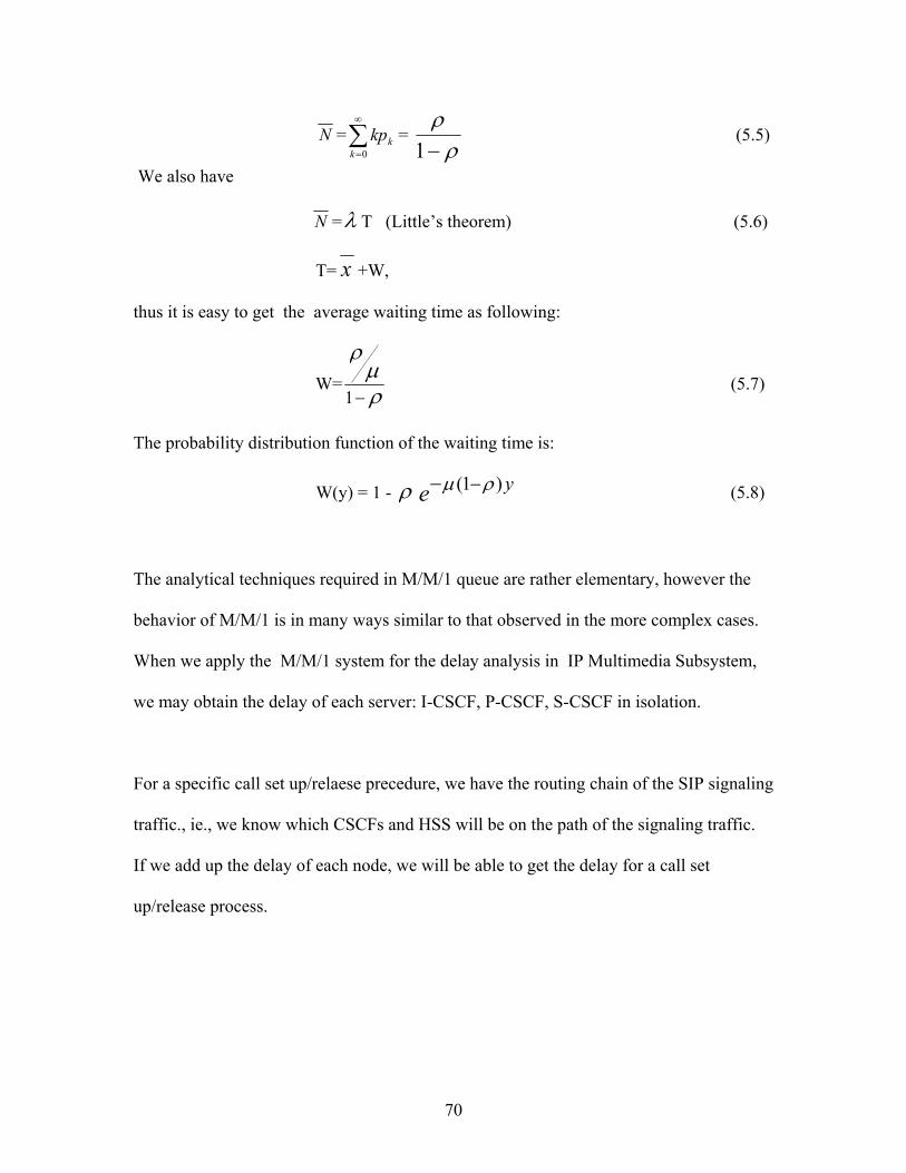
N = = ∑∞
=0kkkp
ρρ−1
(5.5)
We also have
N =λ T (Little’s theorem) (5.6)
T= x +W,
thus it is easy to get the average waiting time as following:
W= ρµ
ρ
−1 (5.7)
The probability distribution function of the waiting time is:
W(y) = 1 - ρ e y)1( ρµ −− (5.8)
The analytical techniques required in M/M/1 queue are rather elementary, however the
behavior of M/M/1 is in many ways similar to that observed in the more complex cases.
When we apply the M/M/1 system for the delay analysis in IP Multimedia Subsystem,
we may obtain the delay of each server: I-CSCF, P-CSCF, S-CSCF in isolation.
For a specific call set up/relaese precedure, we have the routing chain of the SIP signaling
traffic., ie., we know which CSCFs and HSS will be on the path of the signaling traffic.
If we add up the delay of each node, we will be able to get the delay for a call set
up/release process.
70
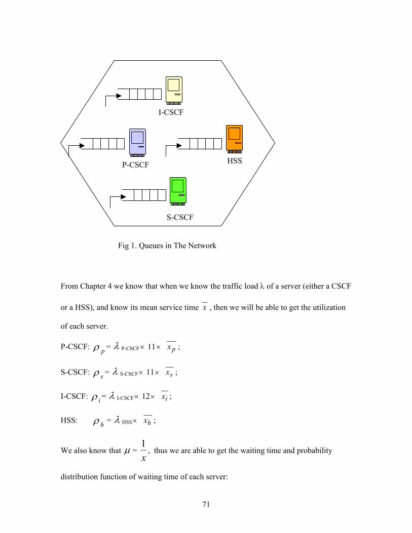
HSS
S-CSCF
P-CSCF
I-CSCF
Fig 1. Queues in The Network
From Chapter 4 we know that when we know the traffic load λ of a server (either a CSCF
or a HSS), and know its mean service time x , then we will be able to get the utilization
of each server.
P-CSCF: ρ p = λ P-CSCF × 11 × px ;
S-CSCF: ρ s = λ S-CSCF × 11 × sx ;
I-CSCF: ρ i = λ I-CSCF × 12× ix ;
HSS: ρ h = λ HSS × hx ;
We also know that µ = x1
, thus we are able to get the waiting time and probability
distribution function of waiting time of each server:
71
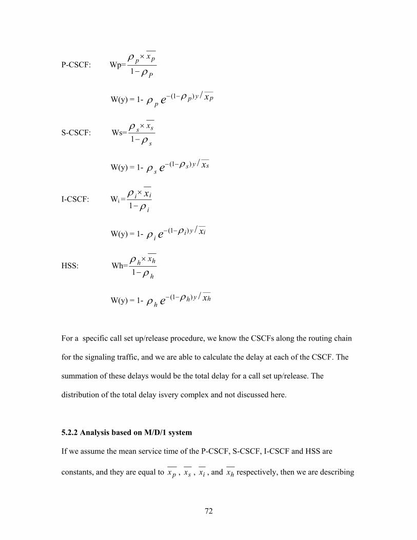
P-CSCF: Wp=ρ
ρ
P
pp x
−
×
1
W(y) = 1- ρ p e x pyp /)1( ρ−−
S-CSCF: Ws=ρ
ρ
s
ss x
−
×
1
W(y) = 1- ρ s e xsys /)1( ρ−−
I-CSCF: Wi = ρρ
i
ii x−
×
1
W(y) = 1- ρ i e xiyi /)1( ρ−−
HSS: Wh=ρ
ρ
h
hh x
−
×
1
W(y) = 1- ρ h e xhyh /)1( ρ−−
For a specific call set up/release procedure, we know the CSCFs along the routing chain
for the signaling traffic, and we are able to calculate the delay at each of the CSCF. The
summation of these delays would be the total delay for a call set up/release. The
distribution of the total delay isvery complex and not discussed here.
5.2.2 Analysis based on M/D/1 system
If we assume the mean service time of the P-CSCF, S-CSCF, I-CSCF and HSS are
constants, and they are equal to px , sx , ix , and hx respectively, then we are describing
72
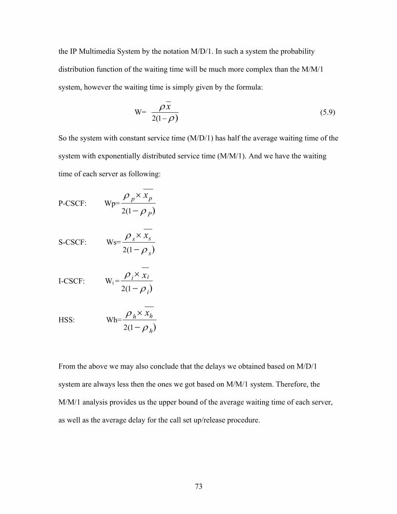
the IP Multimedia System by the notation M/D/1. In such a system the probability
distribution function of the waiting time will be much more complex than the M/M/1
system, however the waiting time is simply given by the formula:
W= )1(2 ρρ−x
(5.9)
So the system with constant service time (M/D/1) has half the average waiting time of the
system with exponentially distributed service time (M/M/1). And we have the waiting
time of each server as following:
P-CSCF: Wp=)1(2 ρ
ρ
P
pp x−
×
S-CSCF: Ws=)1(2 ρ
ρ
s
ss x−×
I-CSCF: Wi =)1(2 ρ
ρ
i
ii x−×
HSS: Wh=)1(2 ρ
ρ
h
hh x−×
From the above we may also conclude that the delays we obtained based on M/D/1
system are always less then the ones we got based on M/M/1 system. Therefore, the
M/M/1 analysis provides us the upper bound of the average waiting time of each server,
as well as the average delay for the call set up/release procedure.
73

CONCLUSION
SIP has been chosen as the signaling protocol for establishing multimedia sessions in
UMTS IP Multimedia Subsystems. In the thesis, we described the operations defined in
UMTS IMS for establishing multimedia sessions. We find that in the call set up/ release
procedure, the signaling traffic hits functional entities (CSCF or HSS) on the routing
chains several times: S-CSCF is hit 11 times, I-CSCF is hit 12 times, P-CSCF is hit 11
times, and HSS is hit one time. Once hit, the functional entity provides some service and
then forwards the traffic on. We consider the functional entities as servers and assume
that the mean service time of servers are the same, then we can identify the bottleneck in
different scenarios. We also get that, in the IP Multimedia Subsystem, which one node is
the bottleneck depends on the traffic distribution in the networks. In a one-server system
where there is only one server of each type, S-CSCF is the bottleneck when the traffic to
and from the roaming subscribers is heavier, however when the traffic to and from the
visitors is heavier, P-CSCF is the bottleneck.
The delay analysis is based on two assumptions of the signaling traffic.
1. If we describe the SIP signaling traffic with M/M/1 notation, assume ρ is the
utilization of the node, and x is the mean service time of the node, we have the delay in
each node given by the formula:
W= )1( ρ
ρ−
x
74

and the waiting time distribution is:
W(y) = 1- ρ e xy /)1( ρ−−
2. If we describe the traffic by M/D/1 notation, then the delay in each node is calculated
by the formula:
W= )1(2 ρρ−x
Which is half of the delay when we assume the traffic to be M/M/1. The probability
distribution function of the waiting time will be much more complex than the M/M/1
system.
In either case, the total delay in a call set up/release procedure is the summation of the
delay of the nodes along the signaling path.
These analyses can be viewed as the first step in the studies of SIP operations in IP
Multimedia Subsystems of UMTS network. Much more work remains to be done on the
topic. Future work can be developed from several aspects:
1. The bottleneck analysis in multi-server systems.
2. Include the user registration and de-registration procedures into the consideration.
3. The probability distribution function of the total waiting time for the call set
up/release procedure.
4. Network simulation to verify the theoretical analysis.
75

REFERENCE
[1] Jeikki Kaaranen, Ari Ahtiainen, etc, UMTS Networks: Architecture, Mobility and
Services John Wiley & Sons, Ltd 2001
[2] Antti Toskala and Harri Holma, WCDMA for UMTS John Wiley & Sons, Ltd 2002
[3] Jochen Schiller, “Mobile Communications” Person Education Limited 2000
[4] Nokia AII-IP Network Vision (Nokia White Paper)
[5] Nokia’s vision of providing end-to end Quality of Service in 3G (Nokia Whitepaper)
[6] Barani Subbiah1, “Transport architecture evolution in UMTS/IMT-2000 cellular
networks”, International Journal of communication systems, 2000; 13:371-385
[7] Evolution to 3G/UMTS Services UMTS FORUM white paper No 1, August 2002
[8] The Third Generation of Mobile Services (AU-SYSTEM white paper)
[9] The Siemens Mobile Core Solution for UMTS
[10] Narayan Parameshwar and Chris Reece, “Advanced SIP Series: SIP and 3GPP”,
Award Solutions, Inc
[11] Narayan Parameshwar, Lachu Aravamudhan and Chris Reece, Advanced SIP
Series: SIP and 3GPP Operations, Award Solutions, Inc
[12] Overview of The Universal Mobile Telecommunication System
http://www.umtsworld.com/technology/overview.htm
[13] N C Lobley, GSM to UMTS - architecture evolution to support multimedia, BT
Technol J Vol 19 No1 January 2001
[14] “Wireless Communications ‘Beyond 3G’” Alcatel Telecommunications Review 1st
Quarter 2001
76

[15] P.Sehier, J-M.Gabriagues, A.Urie “Standadization of 3G mobile systems” Alcatel
Telecommunications Review 1st Quarter 2001
[16] P.Frene, D. Rasseneur, P. Tournassoud “Mobile evolution towards full IP
multimedia” Alcatel Telecommunications Review 1st Quarter 2001
[17] 3GPP TS 23.060: "General Packet Radio Service (GPRS); Service description; Stage
1”
[18] 3GPP TS 23.228: “IP Multimedia Subsystem (IMS); Stage 2”.
[19] 3GPP TS 24.229: “IP Multimedia Call Control Protocol based on SIP and SDP;”
[20] 3GPP TS 33.102: “3G Security; Security Architecture;”
[21] 3GPP TR 23.873 “Feasibility Study for Transport and Control Separation in the PS
CN Domain;”
[22] 3GPP TS 23.207 “End-to-end Quality of Service (QoS) concept and architecture;”
[23] 3GPP TS 24.228 “Signalling flows for the IP multimedia call control based on SIP
and SDP; stage3;”
[24] 3GPP TS 23.002 “Network Architecture (Release 5)”
[25] Leonard Kleinrock, Queuing Systems Volume I John Wiley & Sons, Inc. 1975
77

APPENDICES
Java Program
A. This Java code is programmed to figure out the bottleneck in the two-network system in Chapter 4 (Fig 1).
//class Bottleneck calculates the node that will be bottleneck based on the traffic distribution. class Bottleneck{ public static void main(String args[]){ //double d1 to d14 represents the ratio of traffic load of each scenario to //the total traffic load. double[] hitCount=new double[9]; double d1=0.1; double d2=0.1; double d3=0.05; double d4=0.05; double d5=0.15; double d6=0.15; double d7=0.05; double d8=0.05; double d9=0.05; double d10=0.05; double d11=0.05; double d12=0.05; double d13=0.05; double d14=0.05; //hitCount1 is the total hits on the P-CSCF1 for calls setup and release hitCount[1]=(d1+d2+d3+d4+d5+d6+d7+d8)*11+(d9+d10+d13)*22; //hitCount2 is the total hits on the P-CSCF2 for calls setup and release hitCount[2]=(d1+d2+d3+d4+d5+d6+d7+d8)*11+(d11+d12+d14)*22; //hitCount3 is the total hits on the S-CSCF1 for calls setup and release hitCount[3]=(d1+d2+d3+d4+d9+d10+d11+d12)*11+(d5+d6+d13)*22; //hitCount4 is the total hits on the S-CSCF2 for calls setup and release hitCount[4]=(d1+d2+d3+d4+d9+d10+d11+d12)*11+(d7+d8+d14)*22; //hitCount5 is the total hits on the I-CSCF1 for calls setup and release hitCount[5]=(d2+d3+d5+d6+d10+d11+d13)*12; //hitCount6 is the total hits on the I-CSCF2 for calls setup and release hitCount[6]=(d1+d4+d5+d7+d8+d9+d12+d14)*12; //hitCount7 is the total hits on the HSS1 for calls setup and release hitCount[7]=d2+d3+d5+d6+d10+d11+d13; //hitCount8 is the total hits on the HSS2 for calls setup and release hitCount[8]=d1+d4+d7+d8+d9+d12+d14; for (int l=1;l<=8;l++) { System.out.println("hitCount["+l+"]="+hitCount[l]); } double temp=0; int k=0; for (int m=1; m<=8; m++) { if (temp<hitCount[m]){ temp=hitCount[m]; k=m; } }
78

String bottleneck=" "; switch (k) { case 1: bottleneck="P-CSCF1"; break; case 2: bottleneck="P-CSCF2"; break; case 3: bottleneck="S-CSCF1"; break; case 4: bottleneck="S-CSCF2"; break; case 5: bottleneck="I-CSCF1"; break; case 6: bottleneck="I-CSCF2"; break; case 7: bottleneck="HSS1"; break; case 8: bottleneck="HSS2"; break; } System.out.println("Bottleneck is "+bottleneck); } }
79
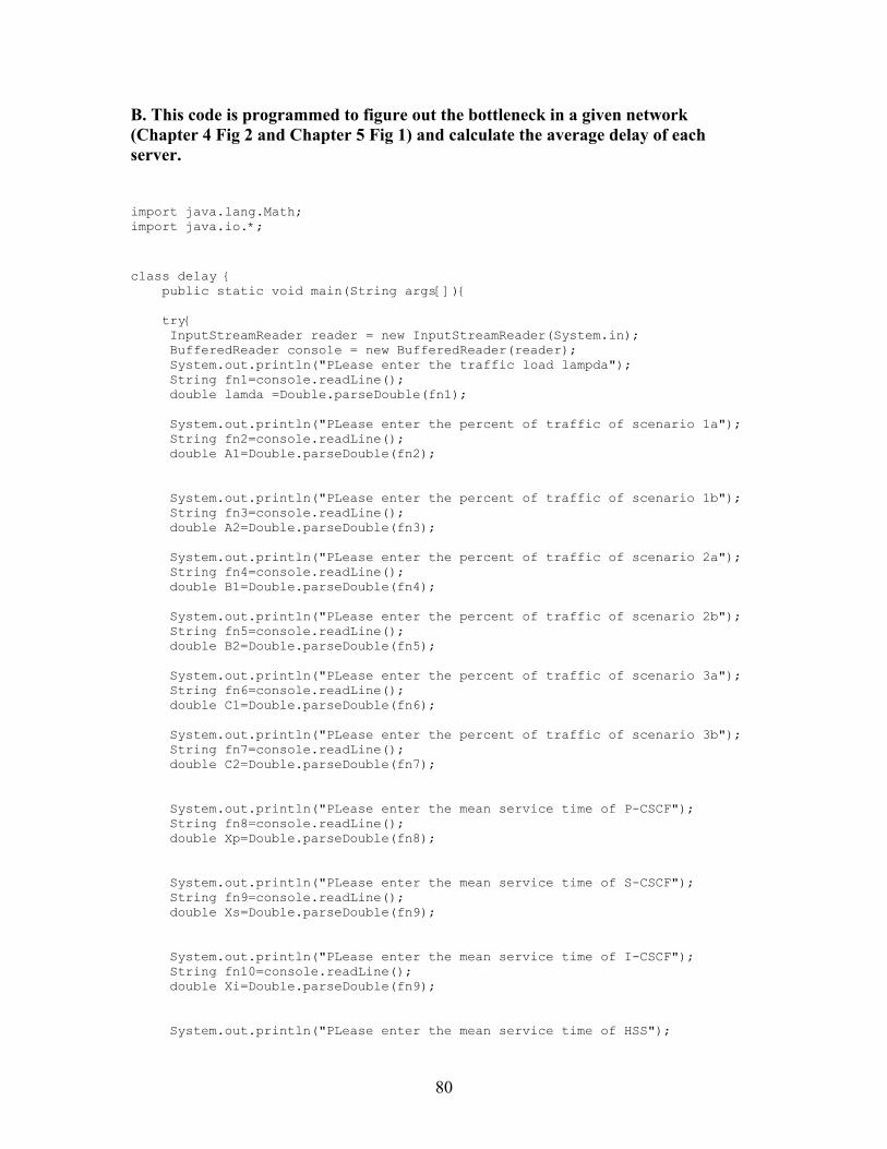
B. This code is programmed to figure out the bottleneck in a given network (Chapter 4 Fig 2 and Chapter 5 Fig 1) and calculate the average delay of each server.
import java.lang.Math; import java.io.*;
class delay { public static void main(String args[]){ try{ InputStreamReader reader = new InputStreamReader(System.in); BufferedReader console = new BufferedReader(reader); System.out.println("PLease enter the traffic load lampda"); String fn1=console.readLine(); double lamda =Double.parseDouble(fn1); System.out.println("PLease enter the percent of traffic of scenario 1a"); String fn2=console.readLine(); double A1=Double.parseDouble(fn2); System.out.println("PLease enter the percent of traffic of scenario 1b"); String fn3=console.readLine(); double A2=Double.parseDouble(fn3); System.out.println("PLease enter the percent of traffic of scenario 2a"); String fn4=console.readLine(); double B1=Double.parseDouble(fn4); System.out.println("PLease enter the percent of traffic of scenario 2b"); String fn5=console.readLine(); double B2=Double.parseDouble(fn5); System.out.println("PLease enter the percent of traffic of scenario 3a"); String fn6=console.readLine(); double C1=Double.parseDouble(fn6); System.out.println("PLease enter the percent of traffic of scenario 3b"); String fn7=console.readLine(); double C2=Double.parseDouble(fn7); System.out.println("PLease enter the mean service time of P-CSCF"); String fn8=console.readLine(); double Xp=Double.parseDouble(fn8); System.out.println("PLease enter the mean service time of S-CSCF"); String fn9=console.readLine(); double Xs=Double.parseDouble(fn9); System.out.println("PLease enter the mean service time of I-CSCF"); String fn10=console.readLine(); double Xi=Double.parseDouble(fn9); System.out.println("PLease enter the mean service time of HSS");
80

String fn11=console.readLine(); double Xh=Double.parseDouble(fn11); /*the utilization of P-CSCF is defined by Rp, the utilization of I-CSCF is defined by Ri, the utilization of S-CSCF is defined by Rs,the utilization of HSS is defined by Rh */ double Rp=(A1+A2+C1+C2)/100*lamda*11*Xp; double Ri=(A2+B2)/100*lamda*12*Xi; double Rs=(A1+A2+B1+B2)/100*lamda*11*Xs; double Rh= (A2+B2)/100*lamda*Xh; if (Rp>=1) { System.out.println("The P-CSCF has been satuarized"); return; } else if (Ri>=1) { System.out.println("The I-CSCF has been satuarized"); return; } else if (Rs>=1) { System.out.println("The S-CSCF has been satuarized"); return; } else if (Rh>=1) { System.out.println("The HSS has been satuarized"); return; } double[] R =new double[5]; R[1]=Rp; R[2]=Ri; R[3]=Rs; R[4]=Rh; double temp=0; int k=0; for (int m=1; m<=4; m++) { if (temp<R[m]){ temp=R[m]; k=m; } } String bottleneck=" "; switch (k) { case 1: bottleneck="P-CSCF"; break; case 2: bottleneck="I-CSCF"; break; case 3: bottleneck="S-CSCF"; break; case 4: bottleneck="HSS"; break; } /*the mean waiting time of P-CSCF is defined by Wp, the mean waiting time of I-CSCF is defined by Wi, the mean waiting time of S-CSCF is defined by Ws,the mean waiting time of HSS is defined by Wh */ double Wp=Rp*Xp/(2*(1-Rp));
81

82
double Wi=Ri*Xi/(2*(1-Ri)); double Ws=Rs*Xs/(2*(1-Rs)); double Wh=Rh*Xh/(2*(1-Rh)); System.out.println("The bottleneck of the network is "+bottleneck); System.out.println("The waiting time of P-CSCF is "+Wp); System.out.println("The waiting time of I-CSCF is "+Wi); System.out.println("The waiting time of S-CSCF is "+Ws); System.out.println("The waiting time of HSS is "+Wh); } //end of try catch(IOException e){ System.out.println(e); System.exit(1); } }//end of main method } //end of class