Embed Size (px)
Citation preview
Details for
Runway Centerline andFeampml MampIon Administration Touchdown Lighting
Systems
AC DATE Advisory Circular
REPRINT INCORPORATES CHANGES 1 2
I
bull I
AC D A T E
A D V I S O R Y CIRCULAR
DEPARTMENT OF TRANSPORTATION FEDERAL AVIATION SUBJECT LIGHTING SYSTEMS
This advisory circular describer standard8 for the designtioni and of runway centerline and touchdown
lighting
2 AC Details for Runway Centerlineand Touchdown Zone Lighting dated May 6 1969 is
3 The publications listed under Appendix 1 Bibliographyare applicable to this advisory circular
4 EXPLANATION CF REVISICNS In addition to minor changer in the textthe following major revisions have been
a Criteria and details added for the installation of and conduit in new rigid and
flexible also applicable to overlays
b Deleted regulator8 and control drawinga
5 Additional of advisorycircular may be obtained from the Department of Publication8 Washington DC
Director Airport8
Initiated by
---
bull
-
AC CHG 2
PARAGRAPH PAGE NO
1 1
1 2 CRITERIA
13
4 DESIGN 2
5 AND MATERIAL 3
6 INSTALLATION 6
7 AND TEST 1 1
8 MAINTENANCE 1 2
APPENDIX 1
BIBLIOGRAPHY 1
2
DRAWINGS (14 PAGET) 1
1 RUNWAY CENTERZINE LAYOUT 1
22
3 SECTION BASE AND ANCHOR AND RIGID 3
4 USE OF JIG NO REFERENCE EDGE 4AVAILABLE BASE AND
5 USE OF ALIGNMENT JIG 5
6 SECTION BASE AND ANCHOR BASE AND 6
Page i
-
AC
PAGE NO
FOR 7
TYPICAL INSTALLATION INSET TYPE LIGHTING 8
9 TYPICAL INSET TYPE FIXTURES 9
10 TYPICAL LAYOUT INSET TYPE LIGHTINGFIXTURES 1 0
11 JUNCTION FOR INSRT FTXTURR INSTALLATIONS 11
12 ONE LINE DIAGRAM TYPICAL SERIES CIRCUIT i 2
13 TYPICAL WIRING DIAGRAM L-828 REGULATOR WITH INTERNAL 13
14 TYPICAL WIRING L-828 REGULATOR WITH PRIMARY OILSWITCH 14
Page
c AC 2
1 INTRODUCTION centerline and touchdown lighting systems are to facilitate landings rollouts and takeoffs The touchshydown Zone light8 are primarily a landing while the centerline
are wed for both landing and takeoff operations
2 CRITERIA Runway centerline lights and touchdown zone lights are required for Category II and Category III runways and for Category Irunway8 used for landing operations below 2400 feet (750 Runway
Runway centerline lights on runwaysfor takeoff below 1600 feet RVR Although
not operationally required runway centerline lights iwe recomnended for I runways greater than 170 feet (50 m) in width or when
by aircraft with approach speeds over 140 knots
3
a Runway Centerline
(1) The lights are located along the runway centerline(15 intervals as shown in Figure 1 The
of lights is offset a maximum of 2 feet to either the right or left side of the runway marking and should be to the
side of the centerline marking from the major taxlwayturnoffs
portion of the lightshying system is color coded to warn pilots of the impendingrunway end Alternate red and white lights are installed asseen from 3000 feet (900 m) to 1000 feet from the runway end and red lights are installed in the last(300 m) portion
srThe last
Displaced On runway8 centerline lights the centerline are extended into the displaced threshold area the displaced area not used for takeoffs or if the displaced area is used is less than 700 feet in length the centerline are blanked out in the direction For displaced threshold areas over700 feet in length and used for takeoffs the centerline lights in the area are circuited separately from the centerline in the nondisplaced runway area to permit
the centerline lights in the displaced areaduring landing operations If the displaced threshold area also contains a medium intensity approach system the controlof the approach lights and displaced threshold area centerline lights are interlocked to insure that when the approach lights are the displaced area centerline lights are and vice
If the displaced threshold area contains a high intenshysity approach lighting system separate circuiting of the censhyterline lights in the displaced area is not required sincethe high approach lights will the center-line lights
Par1
AC CHG 2
b Touchdown Zone Lighting Touchdown zone lights consist of 2 rows of transverse light bars located symmetrically about the runway centershyline as shown in Figure 2 Each light bar consists of 3 unidirectionshyal lights facing the threshold The of light bars extendto a distance of feet or one-half the runway lengthfor runways less than 6000 feet 800 from the threshold with the first light bars located 100 feet from the threshold
4 DESIGN
a eauence of Installation The installation of lights shouldbe done if possible while the runway is under construction or whenan overlay is made This would allow for the installation of L-857 light base and transformer housings with a conduit system which ispreferred Even though lighting may not be programmed at the time ofrunway paving or overlay installation of bases and a conduit systemshould be considered for future installation of inpavement lightingInstallation of the lighting system after paving is verycostly and requires a lengthy shutdown of the runway
b Lavout Provide a design drawing showing the dimensional layoutof the centerline and touchdown zone lighting systems prior toconstruction Correlate this design with current airport drawingsto utilize available ducts and utilities and to avoid conflict with existing or planned facilities
c Runwav Centerline and Touchdown Zone
iampt Fixtures Design these systems for one of theconditions listed below
lsquo(a) In new rigid pavements and new flexible pavements provideaccess to cables and transformers through the use ofconduits and L-857 transformer bases This type ofinstallation will reduce downtime and repair costs when the underground circuits require maintenance SeeFigures 3 and 6
In pavements being overlaid a base and conduit systemas shown in Figures 3 and 6 may be used Thisthe advantages listed in above
In existing pavements provide recesses or holes for thelight-fixtures and shallow sawed for electrical conduc tore This method does not require the installationof bases and conduits See Figure 7
Par 3
AC
(2) Derign 8ach circuit wing 8 for
m with inputof 2400 fixture with 8
To the of current
250 p1U8 1088e8 in to loop
l8CtriC81 lightingOf
high edge control 120 580 8paci81 a8xt p8r8gr8ph
in the control for future 88 8
The load on the of na-exceed the load plur 060 ohm
it not to 8t8y within 8
lt8m drop b8tweex control tower regulator mr8t be con-8t the be 100 Volt8
be either an be
or 8 low DC control circuit be
Of 8 low control circuit the drop within
with the 120
uiDMaat covered by are referred circular
oil u rfyLf rampamp
other of electrical not covered byAviation
to the of electric81
Page 3P u 4
AC
b Light Fixtutee
Provide runway centerline light fixture8 that conform to
Provide light that conformto AC L-8S0 B (Unidirectional)
Provide 2000watt inrrulating (L-844) that to the of AC and
insulating that conform to The treneformer8 8erve a8 a of the light unit from the high voltage of the circuit a filamant opeae the continuity of circuit maintained by the
ing traorrformr
d and Where required provide L-857bare8 that conform to the requirement8 of The
of a cylindrical body with topand cable entrance an internal grounding lug may be
by the The intUMl lug ir ured where interconnected the duct and the ground wire ir inrtalled
through the duct Certain application8 may require addishytional entrance hub8 Provide cover8 a8 in AC
Rwide L-828 current regulator8 thatconformto the of AC The regulatorfor atep control without interrupting load current
ha8 lightning circuit and overcurrent protective a local control are
wired at the factory a8 a are required but are not with the regulator
various rating8 are available
f Control Panel ba in the control if 8pace i8 available provide an L-821
that to of AC The panel of a top plate and
toggle 8titche8 terminal and bright-88a8 required The of the panel and the of
on the for each lightning prevalent lightning
my be the point8 of thtr panal
Auxiliarv Relay Cabinet auxiliary relay cabinetmanufactured in uce with AC can be for
a DC control circuit protection
Page 4 Par S
LI
AC 1
and 20 pilot
cabinet
h Cable Cable the circuit shsll be single( =8AwO insulation
far direct earthburialTgpeB orCln accordance cable for VAC control
A C
the choose to the med Acceptablesubstitutes are cables to Cable
S-66-524 for the c cables and B cables Cables
sawed cuts In
stranded type
or
Connects Rovlde L-823 camectar64zo the cables rhesoc-arsccni~totharequlrementsof AC Use lnstallatlm In for the 10 to the centerllneandtaampdum 6-e leads
Provldeplastlc AC Item L-108
k and AC
1 Concrete AC Item P-501
AC III or and
Federal
Seal a Use described
Select exceed
Par 5 5
AC
Inset Fixtures Fixtures are held in with Item P-606 material liquid and paste
(3) Joints Use joint sealing material conforming to Item P-605across rigid joints
6
a General This section installation methods and techniquesOther methods and techniques and variations of those outlined heremay be used provided they are approved by the appropriate FAA AirportsDistrict Office Correct placement of the lights is of primeimportance to achieve this careful attention to detail is requiredThe light beam must be aligned parallel to the centerline of therunway with a tolerance of The lighting fixture mustbe level and the top of the fixture edge must be between +0and inch from the pavement top see Figure 2 for applicationof tolerance on sections To achieve this result the light base whether in one piece or in sections must be alignedand held in place with jigs until finally secured This method ofinstallation requires surveying that is precise The installation
be with utmost care to avoid remedial action which is verycostly
b Transformer Base (L-857) and Conduit System
(1) New Rigid Pavement This system is preferred but requires careshyful attention to detail during installation of two conditions will be encountered during installation the edge ofexisting pavement available a reference for the new bases or no existing edge is available and bases be set space The availability of an existing pavement edgesimplifies the task of locating the light base in both cases a jig or fixture is required to hold the base inposition while the concrete anchor is placed See Figures 4 and5 Elevation of the base with respect to the runway surface andazimuth with respect to the centerline are two parameters that must be met It is absolutely necessary that the elevation ofthe flange be at least three-quarters of an inch below the pavement surface If less than three-quarters of an inchis left after paving the lighting fixture will be unacceptablyhigh If more than three-quarters of an inch is left adapterrings can be used to bring the lighting fixtures up to the correctelevation Spacers and adapter rings are basically shims and canbe used to bring the lighting fixture to the correct elevationAt each light location make an excavation in the runway base which is large enough to accommodate the light base thereinforcing steel cage and concrete for the anchor After the
Par 5Page 6
AC
excavation is completed light base and steel held in place with the jig See Figure
The jig will establish the elevation and azimuth of thebase and this position the concrete and anchor
placed practice is to each to the system with a length of liquid tight flexibleconduit as in 3 Flexible conduit will allow
in light base before the concrete anchor is placed must be taken while placing the concrete anchorthat neither the jig nor the light bese alignumnt is disturbed The jig Bust remaia place the concrete has set Duringpaving operations the be fitted with a steel cover plate (mud plate) See Figure After the paving trainhas cleared the light base excess concrete from the top
the base and the edge of the around the base should be to a radius The surface of the pavementaround the light base must be level with the surrounding paveshyment dished and mound areas are acceptable After the
has hardened check the elevation of the top flange inrelation to the finished surface It be necessary toinstall a flange ring or flange and spacer ring to bring the light fixture to correct elevation Next install primary cable
and connectors Connect lighting fixture tosecondary cable Install ring gasket and torquebolts to manufacturers the pavingique utiliees more than one of the paving machine the above procedure is altered as follows a sectional light base isrequired after the bottom sectioa has been installed as described above the first pass is The flange isthen cleaned and the next section is with a sealant equal to as Electric Companybetween flanges and in place The paving proceedsand the fixture is installed as above Base and conduit systemsare subject to water intrusion A well-designed system will beequipped with drains at the low
(2) New Pavement A sectional base is required for flexshyible pavement The bottom sectioa of the light base (includingconcrete anchor) and the conduit system are installed in the runway base as described in the preceding paragraph It isthen paved over The light base concrete anchor and conduit
be higher than the base surface After the paving is completed a hole is bored to accuratelylocate the center punch mark of the bottom section cover plateThis hole is used to the actual distance from the topof the pavement to the top of plate An extension
of an inch less than the distance from the pave-at to the top of the plate should be obtained Also obtain a three-quarter-inch flange ring toallow for future adjustment of elevation When
Page 7
AC
- the extension is received a hole one-half inch larger than the diameter of the light should be drilled and the extensionflange ring and light fixture installed as described above The space between the walls of the hole up to the top ofthe adapter ring should be filled with liquid P-606 sealantSee Figure 6
Flexible Overlay The installation of a light base and conduitsystem in a pavement to be overlaid similar to that of a new flexible pavement except the bottom section of the lightbase and the conduit are set in openings made in the existing pavement The anchor and encasement of the conduit will be similar to that described in (2) New Flexible Pavement The use of a short length of liquid tight flexible conduit necessary to allow proper alignment The of the installation as described in the preceding paragraph
Overlay The installation of a lighting base and conduitsystem require8 acomblnation of techniques outlined inpreceding sections of (1) New Rigid Pavement and (3) FlexibleOverlay The base and conduit are installed as in (3) concrete is placed as in (1)
C Inset Installation
(1) Rigid Pavements Drill holes or recesses in the pavements to the light fixtures Saw to accommodate electrical circuits See typical installation details in Figure8 7 8 and
(a) Pavement Drilling and Sawing Provide appraPrimately l4shyinch clearance for sealer material between the bottom and side of the lneet base receptacle and the recessProvide extra depth where sawed wlreways cross pavement joints See Figure 7 for detail
ght Fixtures Install centerline lights to follow the longitudinal contour Place touchdown zone lights level a horizontal plane Unless otherwise epeclfied the tolerance for being level is
Figure 2
Rlor torsquoplacing the inset base receptacle in the drilledhole clean all external surfaces to assure an adequatebond between fixture sealer and pavement Sand blast if necessary Avoid handling the fixtures by the leads
15053404c CHC 1
Orientate the fixture rrmgethe leedrrsquoproperly with to their in the
temporary if required for blocking the entrance the drilled hole The will retain the realer during of the bare receptacleThe for the bare a line parallel with the rummy centerline
are 88ura proper azimuth levetioa and level
Cover the bottom of the receptacle with 6 paateshytype dhe8Fve material Place a quantity of
in tha hole Place the bare in the drilled hole to force the of the at least
inch be taken to work out entrapped air a liquid (paragraph fill the between
the bare of the hole Liquid rearer 8hould be ppliedonly between the-iaret b88e regeptacle and the
of the hole not be applied the Of the hole and the top 888emb1y
to the of the wires in the pavement chamfer or to -inch radiur vertical
of the at and See Figure 10 clean to properbond between pavement material and the If
have been there with a velocity of after sawing to of the
bedryandclean
(d) Wirer place the lo THWN in th wirewaye from ormarr near the runway edge to the light fixture
an number (3 feet on of or device8 to hold the wires in place at least one-half of an inch below the payment 6urshy
wedge8 are not acceptablethe top of the wedge8 below the pavement Splicethe light fixture lead8 to the lO THWN wirer Use pre-
Make the crimped with a tool that require6 a complete crimp before
the Of the Permit no the conductor except at each light If
the in tape or real the of wire8 to prevent the of moisture Seal in the with P-606 Apply in with AC aad the followins
Page 9Par
_
AC --
Pour sealer in until surface of wire covered
If by the manufacturer pour clean eand into the liquid until a alight smountof sand on the Use clean sand that through a Number40
Fill the remainder of the to pavement level withliquid sealer but in case above pavement level
Sealer material extending above pavement surface be removed
Pavement Install light fixtures and wires flexshyible ilar to the procedures in rigid
with the following precautions
lean the holes and before 80 the dry aggregate of the pavement Fe
exposed
(for on fixtures) so that15 minutes
sealant conform8 to P-606 or Specification E-2373 to real wires in
be installed on runways where See 10 When additional
the inset light removed and the bare is fitted with cover paving then applied lightbase and junction box When the paving is completed
the junction box and light bare by coring RemoveAdd to the junction box and light
bare cover box and on bare
d Vault
(2) Exercise campe while working the vault to preventiron stripping or other foreign
collecting on switches and otherCollect and remove all residue as the
Use cover8 or shields during installashytion wiring protect component8 from foreign matter
in accordance with
10 Par 6
Cable Cable shall be in accordance with L-108Advisory Circular In the event of a conflict between
paragraph L-108 this shell govern Providesufficient slack to enable primary cable connections to beabove ground be splices the cable
light Connections of cable to shall be made with L-823 cable the
primary are taped secondary connections not rubber tape by plastic where connector and cable joinedUse only tape where the two halves cable ends if connections not made
7
8 Conduit Inspection and testing of lightingduring ionare important Certain components
be for corrective action after the final installation
Inspect the installed light to if the has been installed in accordance with the instructions and at the proper elevation
Check the alignment of all units to determine if lightingfixtures have been installed in accordance with design and
Check the fixtures and bases to determine if the securinghardware has been tightened in accordance with the
instructions
inspect the lighting fixture8 to determine if the lenser 8nd channels in front of the are clean
Tart vault equipment and circuit8 in AC L-109 and L-108 respectively
Measure and record all operating voltage8 and currents and insulation resistance
b Inset In addition to the above perform the inspection and for these lights concurrently with the because
of -inaccessibility of soxs coxponents ampfore fillingwireways identify and test the secondary series circuit for each
of runway for continuity and insulation to ground Check the insulation 8 (minimum)insul8tion resirtmce tester An acceptable circuit ha8 aof least so After fixtures and wirer are perform a inspection of the sealer in the and around the fixture8 to determine if 811 voids are filled and that is at the proper level with respect to the surface After these
Par 6rsquo Page 11
AC
tests have been performed and the lighting circuits are completedtest the system by continuous operation for a period of not lessthan one-half hour prior to acceptance The tests include the operation of each control not less than 10 times
a
a General Establish a maintenance program at airports where centershyline and touchdown zone lights are installed to insure properoperation and dependable service from the equipment The effectiveshyness of a will soon depreciate unless it is properlytained Maintenance recommendations are contained in AdvisoryCircular Maintenance Guide for Determiningand Cleaning of Centerline and Touchdown Zone Lights
(1) Perform a daily operational check of all lighting fixturesthe runway centerline and touchdown zone lights and
visually inspect the light output If any lamps are out orfixtures are obscured record the location of the fixtures and replace the lamps or top fittings containing the opticallenses Replace lamps when the circuit is deactivated
(2) Clean the lighting fixtures regularly so that the system canmeet performance requirements for low visibility conditionsClean the lens and channel in front of the lens periodically
in accordance with manufacturers recommendations The regularity and type of cleaning will be dictated by the weatherconditions and the location of the fixtures
(3) Snow should be removed from around the lights with powerbroom if practical If it becomes necessary for snowplows to cross lights it is recommended that the blade be lifted
as a last resort should the blade be allowed to come in contact with the light Rubber and plastic-edge snowplowblades are that are especially suited for plowing wet or slushy snow snow removal techniques arecontained in AC
b
(1) Replacement Group replacement may be beneficial and should belsquoconsidered It is that lamps be replaced when the number hours of operation on top brightness stepequals the lamps rated ltfe
(2) Deenergite the circuit supplying the fixturecontaining the burned-out lamp Remove the top assembly A
practice is to replace the complete top assembly and subsequently it in a clean indoor location Replace the seals if they appear to be worn or damaged Beforethe top assembly is replaced clean and dry the unit Properly
Par 7Page 12
3
C
d
Par
AC
position seat all gaskets Tighten all screws bolts or other securing hardware in accordance with manufacturerrsquos
(If fixture8 are not properly secured theymight be damaged by normal aircraft
Removal of Water The lighting fixtures are designed to excludeboth ground and surface water from entering water someshytimes enters and becomes a serious problem particularly wherefreezing temperatures are encountered If the barer or receptaclesfill withlsquowater freezing cause damage to the fixture byshearing the top assembly hardware or rupturing the base or receptacle To prevent this establish a regular schedule forremoving water especially during the fall and winter monthsEstablish a regular schedule for tightening cover bolts If any of the fixtures contain water remove this water and clean and dry the receptacle lamp and electrical contacts Properlyposition andor seat all and tighten the hardware securingthe top assembly in accordance with the instructions
Cable Check home runs of cables with a (minimum) insulashytion resistance tester before the installation been accepted
records of the resistance values obtained In order to check the condition of the system compare periodic reading6 with theinitial values In an acceptable system the initial insulationresistance value is not less than 50 and much higher (in the order of hundreds of megohms) If the periodicchecks reveal progressive deterioration or faults take steps promptly
(1) Make periodic insulation checks by first the regulator Monthly checks are Open the series disconnects Connect one lead of the insulation
to the load side of one disconnect connect the other lead to a proven ground Operate the test equipment inaccordance with instrument
(2) Maintenance personnel must be that high open-circuitvoltage is present when the secondary of an constant current regulator opened Troublerhooting is complicated by the fact that in instances the interconnecting wiresare sealed in the runway pavement8 and the fixtures are located in an active part of the runway For this reason itis important to check the system during the installation and to establish an effective preventive maintenance program
Page 13
AC
Spare Parts The importance of stocking spare parts cannot be overemphasized Spare example should be procured whenthe lighting system into Operation and when the begin indicates that frantic requests for
delivery of replacement lamps often cannot be met by thesupplier Replaceable parts of fixtures and replaceable componentsof regulators should also be stocked for maintenance purposes
Vault Keep the vault (AC Item L-109) uncluttered toprevent dirt from accumulating in control compartmenta and to allowequipment to be accessible at Mount legible warning
in conapicious places Make periodic checks of supply voltage and output current
Test To the light Of inpavement lightingobtain the equipment described in AC Maintenance Guide for Determining Degradation and Cleaning of Centerline and Touchshydown Zone Lights In addition the following equipment is recomshymended
(minimum) insulation resistance testerVolt-ohm meter and clamp-on ammeterRubber safetyHot stick
Other test equipment as required by a particular
ParPage 14
AC 1
1 ( A C ) F e d e r a l
cl2malarr and thereto It axplains the
sale well free AC also
(1) AC and Statue cb Regulatlau3~
(2) AC for and Alz3iortr Dbltrlct
(3) AC 1505$b619 Taxlway
(4) AC Maintenance Guldt
AC for L-821 Alrpti Llghtlq Panel
(6) AC Electrical Cables
for ~cntstant current
(8) AC for L-841 far Pilot of
for andReceptacle
(10) AC FM 6857~1~-pe LQht
AC for
for Airport Llghtlng
(13) AC Removal ar8
1 AC 1 Appendix 1
b latest Issuance of AC Standards for SpecifyingAirports can be In AC be
obtained from the Superintendent of Documents US Office Washiagton DC
copies of Eleckrlficatian AdministratIon Bulletin for Telephmo Cables and
Bulletin for CablesUS
Washington
Cbtaln copies of (ASG)Power Series Airport Liamphtinamp General
Office EavalSupply Depot 5901 Avenue Philadelphia Pennsylvania Attention Code
4 copies of FAA-E-2373 Adhesive for Sealing Wire in Pavements
Configuration Branch IndependenceAvenue SW Waehingtoa DC 20591
5 IFCEA Publlcatlons S-66-524 of
Electrical Energy and Ribber-insulated and Cable for the and af ElectrIcal Energy be obtained
the Electrical 155
Par 1
-
-
touchdown per
0 centerline
bbI whit
r o w - white red
Conterlinr light8 2rsquo to the or left of runwoy lo avoid the centerline paint
2 Thr crntorlinr l i g h t s m a y 0 o f o o f
3 The 3000 foot 1000 foot of runwoy on alternate and light rignol
4 foot of runwoy on rod signal
touchdown light bon not required to locotrd at thr 2 f o r
1 RUNWAY LIGHTING LAYOUT
S9 NVHL I O N 0 1
3 8
V N I
- - - - -
o f
-
~
BASE VARIES
AR
BASE AND OR SUBBASE
ANCHOR
3 SECTION THROUGH BASE AND ANCHOR BASE AND
AC 1 Appendix 2
JIG FOR ALIGNING BASE I
PC CONCRETE ANCHOR
AOJUSTABLE BAR CAGE
SUBBASE
NOTE
COVER PLATE SHOWN FOR ILLUSTRATION ONLY USE OF MUD PLATES CONSTRUCTION RINGS EXTENSIONS ON PAVING
Page 4
rsquo
1
PAVEMENTshy
PLATE SHOWN FOR ONLY USE MUD PLATES RINGS ON
I
L-550 FIXTURE
L-057 BASE
ASPHALT
BASE AND OR L- 555ASE
VARIES
f
VARIES
)
pnee
FIGURE
I2W Itmiddot
bullc-c middot---middot
NL bull
r n-
)
=n
011 bull fll --
- lfiiCifle1 bull ~ __ ltllt_ _ - - -_
bull _ OttbullY __ _ Wtrbull
INSTAIIATIW pErAILS FOil ToucHDOWN ZONE AND CENTERLINE LlGJflS
7 TYPICALWIREWAY
--
-
-
and
JOINT
DE TAIL
NOTES
w i r e s l e s s t h a n below sea t compound s e e S e c t i o n s A A and f o r d i m e n s i o n s
2 d i m e n s i o n s o f cored hole f o r - 8 5 0 f i x t u r e D e p t h
8 TYPICAL INSTALLATUJN DETAILS INSET LIGHTING FIXTURES
-
Appendix 2
HOUSING INSTALLATION
C U L L
SECTION 0
ARE INSTALLED IN WITH L-106
STANDARDS FOR OF
CONNECTORS-NUMBERS REFER TO L
NUMBERS
TYPICAL XTKES - - -
0 Awe
TRANSFORMER CONNECTIONS
01 3lUl3Id
and fobficote bon IO t h e f o o d i n speciftcaiti L- 850
Fill junction bon with o j u n c t i o n b o x l e v e l w i t h t h ei s t o prevenl waler f r o m h fhe junction b o r
t h e bar and t o oermit ins~ollotion amp v i c eProvide o ond grommets lo
b o a
FIGURE 11 JUNCTION BOX FOR INSET FIXTURE INSTALLATIONS
rsquo
lsquo
l
REGULATOR LOCATED
IN VAULT LIGHTS
W A T l S L - 6 5 0 T Y P E A
L - 8 2 8
SERIES LOOP
CENTERLINE ZONE]
CONSTANT CURRENT
REGULATOR LOCATED IN VAULT I TRANSFORMER L-830
200 WATTS IN L -657 BASE
F IXTURE L-
2 0 0 W T Y P E
TOUCHOOWN ZONE1
LIGHTING FIXTURE 200
12 ONE LINE DIAGRAM SERIES LIGHTING
AC Appendix 2
I
L SrsquoLI-rsquo CONTROL PANEL IN TOWER
L -828
CONTROL 7 C U R R E N T WIRES SEE NOTE S T E P - T Y P E
REGULATOR WITH INTERNAL
PRIMARY OIL
ISW I
I rdquo
I
I
OUTPUT
F U S E D C U T O U T
I
LIGHTNING ARRESTOR
CUTOUT W I T H
REGULATOR)TO RUNWAYNOTE LIGHTING CIRCUIT
C I R C U I T U P A P P R O X 3 0 0 0 O R
D R O P I S N O T D R O P I S I N O R A T CORTROI TERYIRALLOU C O N T R O L S E U S E D
13 WIampG REGULATOR WITH CONTROL AND SWITCH
13
AC
NOTES
AS A ELECTRICAL INSTALLATION CONFORM TO APPLICABLE SECTIONS OF THE NATIONAL ELECTRICAL CODE
PANEL TOWER
REMOTE OIL SWITCH
H2 INPUT
L - 8 2 8 CONSTANT CURRENT STEP TYPE
WITH EXTERNAL PRIMARY OIL
SWITCH
O U T P U T
ARRESTOR SEE NOTE 4
LIGHTNING ARRESTOR SEE NOTE4
7 WIRES SEE NOTE
AND CODES
2 MAY SE USED SEE NOTE I FIGURE
WHEN COUNTERPOISE IS IT INSTALLED IN ACCORDANCE WITH ITEM OF STANDARDS FOR SPECIFYING CONSTRUCTION OF AIRPORTS
4 ARRESTORS FURNISHED REGULATOR
FUSED CUTOUT-
14 TYPICAL REGULATOR WITH CONTROL POWER MD PRIMARY OIL SWITCH
I
bull I
AC D A T E
A D V I S O R Y CIRCULAR
DEPARTMENT OF TRANSPORTATION FEDERAL AVIATION SUBJECT LIGHTING SYSTEMS
This advisory circular describer standard8 for the designtioni and of runway centerline and touchdown
lighting
2 AC Details for Runway Centerlineand Touchdown Zone Lighting dated May 6 1969 is
3 The publications listed under Appendix 1 Bibliographyare applicable to this advisory circular
4 EXPLANATION CF REVISICNS In addition to minor changer in the textthe following major revisions have been
a Criteria and details added for the installation of and conduit in new rigid and
flexible also applicable to overlays
b Deleted regulator8 and control drawinga
5 Additional of advisorycircular may be obtained from the Department of Publication8 Washington DC
Director Airport8
Initiated by
---
bull
-
AC CHG 2
PARAGRAPH PAGE NO
1 1
1 2 CRITERIA
13
4 DESIGN 2
5 AND MATERIAL 3
6 INSTALLATION 6
7 AND TEST 1 1
8 MAINTENANCE 1 2
APPENDIX 1
BIBLIOGRAPHY 1
2
DRAWINGS (14 PAGET) 1
1 RUNWAY CENTERZINE LAYOUT 1
22
3 SECTION BASE AND ANCHOR AND RIGID 3
4 USE OF JIG NO REFERENCE EDGE 4AVAILABLE BASE AND
5 USE OF ALIGNMENT JIG 5
6 SECTION BASE AND ANCHOR BASE AND 6
Page i
-
AC
PAGE NO
FOR 7
TYPICAL INSTALLATION INSET TYPE LIGHTING 8
9 TYPICAL INSET TYPE FIXTURES 9
10 TYPICAL LAYOUT INSET TYPE LIGHTINGFIXTURES 1 0
11 JUNCTION FOR INSRT FTXTURR INSTALLATIONS 11
12 ONE LINE DIAGRAM TYPICAL SERIES CIRCUIT i 2
13 TYPICAL WIRING DIAGRAM L-828 REGULATOR WITH INTERNAL 13
14 TYPICAL WIRING L-828 REGULATOR WITH PRIMARY OILSWITCH 14
Page
c AC 2
1 INTRODUCTION centerline and touchdown lighting systems are to facilitate landings rollouts and takeoffs The touchshydown Zone light8 are primarily a landing while the centerline
are wed for both landing and takeoff operations
2 CRITERIA Runway centerline lights and touchdown zone lights are required for Category II and Category III runways and for Category Irunway8 used for landing operations below 2400 feet (750 Runway
Runway centerline lights on runwaysfor takeoff below 1600 feet RVR Although
not operationally required runway centerline lights iwe recomnended for I runways greater than 170 feet (50 m) in width or when
by aircraft with approach speeds over 140 knots
3
a Runway Centerline
(1) The lights are located along the runway centerline(15 intervals as shown in Figure 1 The
of lights is offset a maximum of 2 feet to either the right or left side of the runway marking and should be to the
side of the centerline marking from the major taxlwayturnoffs
portion of the lightshying system is color coded to warn pilots of the impendingrunway end Alternate red and white lights are installed asseen from 3000 feet (900 m) to 1000 feet from the runway end and red lights are installed in the last(300 m) portion
srThe last
Displaced On runway8 centerline lights the centerline are extended into the displaced threshold area the displaced area not used for takeoffs or if the displaced area is used is less than 700 feet in length the centerline are blanked out in the direction For displaced threshold areas over700 feet in length and used for takeoffs the centerline lights in the area are circuited separately from the centerline in the nondisplaced runway area to permit
the centerline lights in the displaced areaduring landing operations If the displaced threshold area also contains a medium intensity approach system the controlof the approach lights and displaced threshold area centerline lights are interlocked to insure that when the approach lights are the displaced area centerline lights are and vice
If the displaced threshold area contains a high intenshysity approach lighting system separate circuiting of the censhyterline lights in the displaced area is not required sincethe high approach lights will the center-line lights
Par1
AC CHG 2
b Touchdown Zone Lighting Touchdown zone lights consist of 2 rows of transverse light bars located symmetrically about the runway centershyline as shown in Figure 2 Each light bar consists of 3 unidirectionshyal lights facing the threshold The of light bars extendto a distance of feet or one-half the runway lengthfor runways less than 6000 feet 800 from the threshold with the first light bars located 100 feet from the threshold
4 DESIGN
a eauence of Installation The installation of lights shouldbe done if possible while the runway is under construction or whenan overlay is made This would allow for the installation of L-857 light base and transformer housings with a conduit system which ispreferred Even though lighting may not be programmed at the time ofrunway paving or overlay installation of bases and a conduit systemshould be considered for future installation of inpavement lightingInstallation of the lighting system after paving is verycostly and requires a lengthy shutdown of the runway
b Lavout Provide a design drawing showing the dimensional layoutof the centerline and touchdown zone lighting systems prior toconstruction Correlate this design with current airport drawingsto utilize available ducts and utilities and to avoid conflict with existing or planned facilities
c Runwav Centerline and Touchdown Zone
iampt Fixtures Design these systems for one of theconditions listed below
lsquo(a) In new rigid pavements and new flexible pavements provideaccess to cables and transformers through the use ofconduits and L-857 transformer bases This type ofinstallation will reduce downtime and repair costs when the underground circuits require maintenance SeeFigures 3 and 6
In pavements being overlaid a base and conduit systemas shown in Figures 3 and 6 may be used Thisthe advantages listed in above
In existing pavements provide recesses or holes for thelight-fixtures and shallow sawed for electrical conduc tore This method does not require the installationof bases and conduits See Figure 7
Par 3
AC
(2) Derign 8ach circuit wing 8 for
m with inputof 2400 fixture with 8
To the of current
250 p1U8 1088e8 in to loop
l8CtriC81 lightingOf
high edge control 120 580 8paci81 a8xt p8r8gr8ph
in the control for future 88 8
The load on the of na-exceed the load plur 060 ohm
it not to 8t8y within 8
lt8m drop b8tweex control tower regulator mr8t be con-8t the be 100 Volt8
be either an be
or 8 low DC control circuit be
Of 8 low control circuit the drop within
with the 120
uiDMaat covered by are referred circular
oil u rfyLf rampamp
other of electrical not covered byAviation
to the of electric81
Page 3P u 4
AC
b Light Fixtutee
Provide runway centerline light fixture8 that conform to
Provide light that conformto AC L-8S0 B (Unidirectional)
Provide 2000watt inrrulating (L-844) that to the of AC and
insulating that conform to The treneformer8 8erve a8 a of the light unit from the high voltage of the circuit a filamant opeae the continuity of circuit maintained by the
ing traorrformr
d and Where required provide L-857bare8 that conform to the requirement8 of The
of a cylindrical body with topand cable entrance an internal grounding lug may be
by the The intUMl lug ir ured where interconnected the duct and the ground wire ir inrtalled
through the duct Certain application8 may require addishytional entrance hub8 Provide cover8 a8 in AC
Rwide L-828 current regulator8 thatconformto the of AC The regulatorfor atep control without interrupting load current
ha8 lightning circuit and overcurrent protective a local control are
wired at the factory a8 a are required but are not with the regulator
various rating8 are available
f Control Panel ba in the control if 8pace i8 available provide an L-821
that to of AC The panel of a top plate and
toggle 8titche8 terminal and bright-88a8 required The of the panel and the of
on the for each lightning prevalent lightning
my be the point8 of thtr panal
Auxiliarv Relay Cabinet auxiliary relay cabinetmanufactured in uce with AC can be for
a DC control circuit protection
Page 4 Par S
LI
AC 1
and 20 pilot
cabinet
h Cable Cable the circuit shsll be single( =8AwO insulation
far direct earthburialTgpeB orCln accordance cable for VAC control
A C
the choose to the med Acceptablesubstitutes are cables to Cable
S-66-524 for the c cables and B cables Cables
sawed cuts In
stranded type
or
Connects Rovlde L-823 camectar64zo the cables rhesoc-arsccni~totharequlrementsof AC Use lnstallatlm In for the 10 to the centerllneandtaampdum 6-e leads
Provldeplastlc AC Item L-108
k and AC
1 Concrete AC Item P-501
AC III or and
Federal
Seal a Use described
Select exceed
Par 5 5
AC
Inset Fixtures Fixtures are held in with Item P-606 material liquid and paste
(3) Joints Use joint sealing material conforming to Item P-605across rigid joints
6
a General This section installation methods and techniquesOther methods and techniques and variations of those outlined heremay be used provided they are approved by the appropriate FAA AirportsDistrict Office Correct placement of the lights is of primeimportance to achieve this careful attention to detail is requiredThe light beam must be aligned parallel to the centerline of therunway with a tolerance of The lighting fixture mustbe level and the top of the fixture edge must be between +0and inch from the pavement top see Figure 2 for applicationof tolerance on sections To achieve this result the light base whether in one piece or in sections must be alignedand held in place with jigs until finally secured This method ofinstallation requires surveying that is precise The installation
be with utmost care to avoid remedial action which is verycostly
b Transformer Base (L-857) and Conduit System
(1) New Rigid Pavement This system is preferred but requires careshyful attention to detail during installation of two conditions will be encountered during installation the edge ofexisting pavement available a reference for the new bases or no existing edge is available and bases be set space The availability of an existing pavement edgesimplifies the task of locating the light base in both cases a jig or fixture is required to hold the base inposition while the concrete anchor is placed See Figures 4 and5 Elevation of the base with respect to the runway surface andazimuth with respect to the centerline are two parameters that must be met It is absolutely necessary that the elevation ofthe flange be at least three-quarters of an inch below the pavement surface If less than three-quarters of an inchis left after paving the lighting fixture will be unacceptablyhigh If more than three-quarters of an inch is left adapterrings can be used to bring the lighting fixtures up to the correctelevation Spacers and adapter rings are basically shims and canbe used to bring the lighting fixture to the correct elevationAt each light location make an excavation in the runway base which is large enough to accommodate the light base thereinforcing steel cage and concrete for the anchor After the
Par 5Page 6
AC
excavation is completed light base and steel held in place with the jig See Figure
The jig will establish the elevation and azimuth of thebase and this position the concrete and anchor
placed practice is to each to the system with a length of liquid tight flexibleconduit as in 3 Flexible conduit will allow
in light base before the concrete anchor is placed must be taken while placing the concrete anchorthat neither the jig nor the light bese alignumnt is disturbed The jig Bust remaia place the concrete has set Duringpaving operations the be fitted with a steel cover plate (mud plate) See Figure After the paving trainhas cleared the light base excess concrete from the top
the base and the edge of the around the base should be to a radius The surface of the pavementaround the light base must be level with the surrounding paveshyment dished and mound areas are acceptable After the
has hardened check the elevation of the top flange inrelation to the finished surface It be necessary toinstall a flange ring or flange and spacer ring to bring the light fixture to correct elevation Next install primary cable
and connectors Connect lighting fixture tosecondary cable Install ring gasket and torquebolts to manufacturers the pavingique utiliees more than one of the paving machine the above procedure is altered as follows a sectional light base isrequired after the bottom sectioa has been installed as described above the first pass is The flange isthen cleaned and the next section is with a sealant equal to as Electric Companybetween flanges and in place The paving proceedsand the fixture is installed as above Base and conduit systemsare subject to water intrusion A well-designed system will beequipped with drains at the low
(2) New Pavement A sectional base is required for flexshyible pavement The bottom sectioa of the light base (includingconcrete anchor) and the conduit system are installed in the runway base as described in the preceding paragraph It isthen paved over The light base concrete anchor and conduit
be higher than the base surface After the paving is completed a hole is bored to accuratelylocate the center punch mark of the bottom section cover plateThis hole is used to the actual distance from the topof the pavement to the top of plate An extension
of an inch less than the distance from the pave-at to the top of the plate should be obtained Also obtain a three-quarter-inch flange ring toallow for future adjustment of elevation When
Page 7
AC
- the extension is received a hole one-half inch larger than the diameter of the light should be drilled and the extensionflange ring and light fixture installed as described above The space between the walls of the hole up to the top ofthe adapter ring should be filled with liquid P-606 sealantSee Figure 6
Flexible Overlay The installation of a light base and conduitsystem in a pavement to be overlaid similar to that of a new flexible pavement except the bottom section of the lightbase and the conduit are set in openings made in the existing pavement The anchor and encasement of the conduit will be similar to that described in (2) New Flexible Pavement The use of a short length of liquid tight flexible conduit necessary to allow proper alignment The of the installation as described in the preceding paragraph
Overlay The installation of a lighting base and conduitsystem require8 acomblnation of techniques outlined inpreceding sections of (1) New Rigid Pavement and (3) FlexibleOverlay The base and conduit are installed as in (3) concrete is placed as in (1)
C Inset Installation
(1) Rigid Pavements Drill holes or recesses in the pavements to the light fixtures Saw to accommodate electrical circuits See typical installation details in Figure8 7 8 and
(a) Pavement Drilling and Sawing Provide appraPrimately l4shyinch clearance for sealer material between the bottom and side of the lneet base receptacle and the recessProvide extra depth where sawed wlreways cross pavement joints See Figure 7 for detail
ght Fixtures Install centerline lights to follow the longitudinal contour Place touchdown zone lights level a horizontal plane Unless otherwise epeclfied the tolerance for being level is
Figure 2
Rlor torsquoplacing the inset base receptacle in the drilledhole clean all external surfaces to assure an adequatebond between fixture sealer and pavement Sand blast if necessary Avoid handling the fixtures by the leads
15053404c CHC 1
Orientate the fixture rrmgethe leedrrsquoproperly with to their in the
temporary if required for blocking the entrance the drilled hole The will retain the realer during of the bare receptacleThe for the bare a line parallel with the rummy centerline
are 88ura proper azimuth levetioa and level
Cover the bottom of the receptacle with 6 paateshytype dhe8Fve material Place a quantity of
in tha hole Place the bare in the drilled hole to force the of the at least
inch be taken to work out entrapped air a liquid (paragraph fill the between
the bare of the hole Liquid rearer 8hould be ppliedonly between the-iaret b88e regeptacle and the
of the hole not be applied the Of the hole and the top 888emb1y
to the of the wires in the pavement chamfer or to -inch radiur vertical
of the at and See Figure 10 clean to properbond between pavement material and the If
have been there with a velocity of after sawing to of the
bedryandclean
(d) Wirer place the lo THWN in th wirewaye from ormarr near the runway edge to the light fixture
an number (3 feet on of or device8 to hold the wires in place at least one-half of an inch below the payment 6urshy
wedge8 are not acceptablethe top of the wedge8 below the pavement Splicethe light fixture lead8 to the lO THWN wirer Use pre-
Make the crimped with a tool that require6 a complete crimp before
the Of the Permit no the conductor except at each light If
the in tape or real the of wire8 to prevent the of moisture Seal in the with P-606 Apply in with AC aad the followins
Page 9Par
_
AC --
Pour sealer in until surface of wire covered
If by the manufacturer pour clean eand into the liquid until a alight smountof sand on the Use clean sand that through a Number40
Fill the remainder of the to pavement level withliquid sealer but in case above pavement level
Sealer material extending above pavement surface be removed
Pavement Install light fixtures and wires flexshyible ilar to the procedures in rigid
with the following precautions
lean the holes and before 80 the dry aggregate of the pavement Fe
exposed
(for on fixtures) so that15 minutes
sealant conform8 to P-606 or Specification E-2373 to real wires in
be installed on runways where See 10 When additional
the inset light removed and the bare is fitted with cover paving then applied lightbase and junction box When the paving is completed
the junction box and light bare by coring RemoveAdd to the junction box and light
bare cover box and on bare
d Vault
(2) Exercise campe while working the vault to preventiron stripping or other foreign
collecting on switches and otherCollect and remove all residue as the
Use cover8 or shields during installashytion wiring protect component8 from foreign matter
in accordance with
10 Par 6
Cable Cable shall be in accordance with L-108Advisory Circular In the event of a conflict between
paragraph L-108 this shell govern Providesufficient slack to enable primary cable connections to beabove ground be splices the cable
light Connections of cable to shall be made with L-823 cable the
primary are taped secondary connections not rubber tape by plastic where connector and cable joinedUse only tape where the two halves cable ends if connections not made
7
8 Conduit Inspection and testing of lightingduring ionare important Certain components
be for corrective action after the final installation
Inspect the installed light to if the has been installed in accordance with the instructions and at the proper elevation
Check the alignment of all units to determine if lightingfixtures have been installed in accordance with design and
Check the fixtures and bases to determine if the securinghardware has been tightened in accordance with the
instructions
inspect the lighting fixture8 to determine if the lenser 8nd channels in front of the are clean
Tart vault equipment and circuit8 in AC L-109 and L-108 respectively
Measure and record all operating voltage8 and currents and insulation resistance
b Inset In addition to the above perform the inspection and for these lights concurrently with the because
of -inaccessibility of soxs coxponents ampfore fillingwireways identify and test the secondary series circuit for each
of runway for continuity and insulation to ground Check the insulation 8 (minimum)insul8tion resirtmce tester An acceptable circuit ha8 aof least so After fixtures and wirer are perform a inspection of the sealer in the and around the fixture8 to determine if 811 voids are filled and that is at the proper level with respect to the surface After these
Par 6rsquo Page 11
AC
tests have been performed and the lighting circuits are completedtest the system by continuous operation for a period of not lessthan one-half hour prior to acceptance The tests include the operation of each control not less than 10 times
a
a General Establish a maintenance program at airports where centershyline and touchdown zone lights are installed to insure properoperation and dependable service from the equipment The effectiveshyness of a will soon depreciate unless it is properlytained Maintenance recommendations are contained in AdvisoryCircular Maintenance Guide for Determiningand Cleaning of Centerline and Touchdown Zone Lights
(1) Perform a daily operational check of all lighting fixturesthe runway centerline and touchdown zone lights and
visually inspect the light output If any lamps are out orfixtures are obscured record the location of the fixtures and replace the lamps or top fittings containing the opticallenses Replace lamps when the circuit is deactivated
(2) Clean the lighting fixtures regularly so that the system canmeet performance requirements for low visibility conditionsClean the lens and channel in front of the lens periodically
in accordance with manufacturers recommendations The regularity and type of cleaning will be dictated by the weatherconditions and the location of the fixtures
(3) Snow should be removed from around the lights with powerbroom if practical If it becomes necessary for snowplows to cross lights it is recommended that the blade be lifted
as a last resort should the blade be allowed to come in contact with the light Rubber and plastic-edge snowplowblades are that are especially suited for plowing wet or slushy snow snow removal techniques arecontained in AC
b
(1) Replacement Group replacement may be beneficial and should belsquoconsidered It is that lamps be replaced when the number hours of operation on top brightness stepequals the lamps rated ltfe
(2) Deenergite the circuit supplying the fixturecontaining the burned-out lamp Remove the top assembly A
practice is to replace the complete top assembly and subsequently it in a clean indoor location Replace the seals if they appear to be worn or damaged Beforethe top assembly is replaced clean and dry the unit Properly
Par 7Page 12
3
C
d
Par
AC
position seat all gaskets Tighten all screws bolts or other securing hardware in accordance with manufacturerrsquos
(If fixture8 are not properly secured theymight be damaged by normal aircraft
Removal of Water The lighting fixtures are designed to excludeboth ground and surface water from entering water someshytimes enters and becomes a serious problem particularly wherefreezing temperatures are encountered If the barer or receptaclesfill withlsquowater freezing cause damage to the fixture byshearing the top assembly hardware or rupturing the base or receptacle To prevent this establish a regular schedule forremoving water especially during the fall and winter monthsEstablish a regular schedule for tightening cover bolts If any of the fixtures contain water remove this water and clean and dry the receptacle lamp and electrical contacts Properlyposition andor seat all and tighten the hardware securingthe top assembly in accordance with the instructions
Cable Check home runs of cables with a (minimum) insulashytion resistance tester before the installation been accepted
records of the resistance values obtained In order to check the condition of the system compare periodic reading6 with theinitial values In an acceptable system the initial insulationresistance value is not less than 50 and much higher (in the order of hundreds of megohms) If the periodicchecks reveal progressive deterioration or faults take steps promptly
(1) Make periodic insulation checks by first the regulator Monthly checks are Open the series disconnects Connect one lead of the insulation
to the load side of one disconnect connect the other lead to a proven ground Operate the test equipment inaccordance with instrument
(2) Maintenance personnel must be that high open-circuitvoltage is present when the secondary of an constant current regulator opened Troublerhooting is complicated by the fact that in instances the interconnecting wiresare sealed in the runway pavement8 and the fixtures are located in an active part of the runway For this reason itis important to check the system during the installation and to establish an effective preventive maintenance program
Page 13
AC
Spare Parts The importance of stocking spare parts cannot be overemphasized Spare example should be procured whenthe lighting system into Operation and when the begin indicates that frantic requests for
delivery of replacement lamps often cannot be met by thesupplier Replaceable parts of fixtures and replaceable componentsof regulators should also be stocked for maintenance purposes
Vault Keep the vault (AC Item L-109) uncluttered toprevent dirt from accumulating in control compartmenta and to allowequipment to be accessible at Mount legible warning
in conapicious places Make periodic checks of supply voltage and output current
Test To the light Of inpavement lightingobtain the equipment described in AC Maintenance Guide for Determining Degradation and Cleaning of Centerline and Touchshydown Zone Lights In addition the following equipment is recomshymended
(minimum) insulation resistance testerVolt-ohm meter and clamp-on ammeterRubber safetyHot stick
Other test equipment as required by a particular
ParPage 14
AC 1
1 ( A C ) F e d e r a l
cl2malarr and thereto It axplains the
sale well free AC also
(1) AC and Statue cb Regulatlau3~
(2) AC for and Alz3iortr Dbltrlct
(3) AC 1505$b619 Taxlway
(4) AC Maintenance Guldt
AC for L-821 Alrpti Llghtlq Panel
(6) AC Electrical Cables
for ~cntstant current
(8) AC for L-841 far Pilot of
for andReceptacle
(10) AC FM 6857~1~-pe LQht
AC for
for Airport Llghtlng
(13) AC Removal ar8
1 AC 1 Appendix 1
b latest Issuance of AC Standards for SpecifyingAirports can be In AC be
obtained from the Superintendent of Documents US Office Washiagton DC
copies of Eleckrlficatian AdministratIon Bulletin for Telephmo Cables and
Bulletin for CablesUS
Washington
Cbtaln copies of (ASG)Power Series Airport Liamphtinamp General
Office EavalSupply Depot 5901 Avenue Philadelphia Pennsylvania Attention Code
4 copies of FAA-E-2373 Adhesive for Sealing Wire in Pavements
Configuration Branch IndependenceAvenue SW Waehingtoa DC 20591
5 IFCEA Publlcatlons S-66-524 of
Electrical Energy and Ribber-insulated and Cable for the and af ElectrIcal Energy be obtained
the Electrical 155
Par 1
-
-
touchdown per
0 centerline
bbI whit
r o w - white red
Conterlinr light8 2rsquo to the or left of runwoy lo avoid the centerline paint
2 Thr crntorlinr l i g h t s m a y 0 o f o o f
3 The 3000 foot 1000 foot of runwoy on alternate and light rignol
4 foot of runwoy on rod signal
touchdown light bon not required to locotrd at thr 2 f o r
1 RUNWAY LIGHTING LAYOUT
S9 NVHL I O N 0 1
3 8
V N I
- - - - -
o f
-
~
BASE VARIES
AR
BASE AND OR SUBBASE
ANCHOR
3 SECTION THROUGH BASE AND ANCHOR BASE AND
AC 1 Appendix 2
JIG FOR ALIGNING BASE I
PC CONCRETE ANCHOR
AOJUSTABLE BAR CAGE
SUBBASE
NOTE
COVER PLATE SHOWN FOR ILLUSTRATION ONLY USE OF MUD PLATES CONSTRUCTION RINGS EXTENSIONS ON PAVING
Page 4
rsquo
1
PAVEMENTshy
PLATE SHOWN FOR ONLY USE MUD PLATES RINGS ON
I
L-550 FIXTURE
L-057 BASE
ASPHALT
BASE AND OR L- 555ASE
VARIES
f
VARIES
)
pnee
FIGURE
I2W Itmiddot
bullc-c middot---middot
NL bull
r n-
)
=n
011 bull fll --
- lfiiCifle1 bull ~ __ ltllt_ _ - - -_
bull _ OttbullY __ _ Wtrbull
INSTAIIATIW pErAILS FOil ToucHDOWN ZONE AND CENTERLINE LlGJflS
7 TYPICALWIREWAY
--
-
-
and
JOINT
DE TAIL
NOTES
w i r e s l e s s t h a n below sea t compound s e e S e c t i o n s A A and f o r d i m e n s i o n s
2 d i m e n s i o n s o f cored hole f o r - 8 5 0 f i x t u r e D e p t h
8 TYPICAL INSTALLATUJN DETAILS INSET LIGHTING FIXTURES
-
Appendix 2
HOUSING INSTALLATION
C U L L
SECTION 0
ARE INSTALLED IN WITH L-106
STANDARDS FOR OF
CONNECTORS-NUMBERS REFER TO L
NUMBERS
TYPICAL XTKES - - -
0 Awe
TRANSFORMER CONNECTIONS
01 3lUl3Id
and fobficote bon IO t h e f o o d i n speciftcaiti L- 850
Fill junction bon with o j u n c t i o n b o x l e v e l w i t h t h ei s t o prevenl waler f r o m h fhe junction b o r
t h e bar and t o oermit ins~ollotion amp v i c eProvide o ond grommets lo
b o a
FIGURE 11 JUNCTION BOX FOR INSET FIXTURE INSTALLATIONS
rsquo
lsquo
l
REGULATOR LOCATED
IN VAULT LIGHTS
W A T l S L - 6 5 0 T Y P E A
L - 8 2 8
SERIES LOOP
CENTERLINE ZONE]
CONSTANT CURRENT
REGULATOR LOCATED IN VAULT I TRANSFORMER L-830
200 WATTS IN L -657 BASE
F IXTURE L-
2 0 0 W T Y P E
TOUCHOOWN ZONE1
LIGHTING FIXTURE 200
12 ONE LINE DIAGRAM SERIES LIGHTING
AC Appendix 2
I
L SrsquoLI-rsquo CONTROL PANEL IN TOWER
L -828
CONTROL 7 C U R R E N T WIRES SEE NOTE S T E P - T Y P E
REGULATOR WITH INTERNAL
PRIMARY OIL
ISW I
I rdquo
I
I
OUTPUT
F U S E D C U T O U T
I
LIGHTNING ARRESTOR
CUTOUT W I T H
REGULATOR)TO RUNWAYNOTE LIGHTING CIRCUIT
C I R C U I T U P A P P R O X 3 0 0 0 O R
D R O P I S N O T D R O P I S I N O R A T CORTROI TERYIRALLOU C O N T R O L S E U S E D
13 WIampG REGULATOR WITH CONTROL AND SWITCH
13
AC
NOTES
AS A ELECTRICAL INSTALLATION CONFORM TO APPLICABLE SECTIONS OF THE NATIONAL ELECTRICAL CODE
PANEL TOWER
REMOTE OIL SWITCH
H2 INPUT
L - 8 2 8 CONSTANT CURRENT STEP TYPE
WITH EXTERNAL PRIMARY OIL
SWITCH
O U T P U T
ARRESTOR SEE NOTE 4
LIGHTNING ARRESTOR SEE NOTE4
7 WIRES SEE NOTE
AND CODES
2 MAY SE USED SEE NOTE I FIGURE
WHEN COUNTERPOISE IS IT INSTALLED IN ACCORDANCE WITH ITEM OF STANDARDS FOR SPECIFYING CONSTRUCTION OF AIRPORTS
4 ARRESTORS FURNISHED REGULATOR
FUSED CUTOUT-
14 TYPICAL REGULATOR WITH CONTROL POWER MD PRIMARY OIL SWITCH
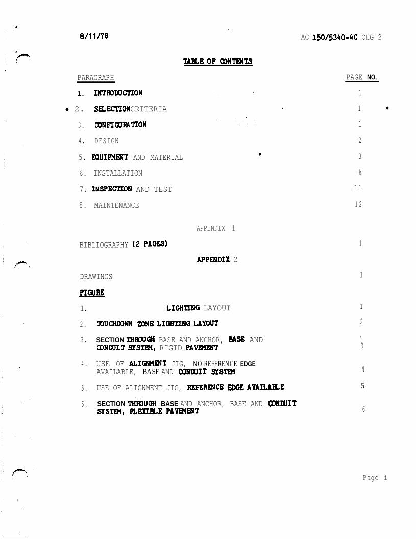
AC CHG 2
PARAGRAPH PAGE NO
1 1
1 2 CRITERIA
13
4 DESIGN 2
5 AND MATERIAL 3
6 INSTALLATION 6
7 AND TEST 1 1
8 MAINTENANCE 1 2
APPENDIX 1
BIBLIOGRAPHY 1
2
DRAWINGS (14 PAGET) 1
1 RUNWAY CENTERZINE LAYOUT 1
22
3 SECTION BASE AND ANCHOR AND RIGID 3
4 USE OF JIG NO REFERENCE EDGE 4AVAILABLE BASE AND
5 USE OF ALIGNMENT JIG 5
6 SECTION BASE AND ANCHOR BASE AND 6
Page i
-
AC
PAGE NO
FOR 7
TYPICAL INSTALLATION INSET TYPE LIGHTING 8
9 TYPICAL INSET TYPE FIXTURES 9
10 TYPICAL LAYOUT INSET TYPE LIGHTINGFIXTURES 1 0
11 JUNCTION FOR INSRT FTXTURR INSTALLATIONS 11
12 ONE LINE DIAGRAM TYPICAL SERIES CIRCUIT i 2
13 TYPICAL WIRING DIAGRAM L-828 REGULATOR WITH INTERNAL 13
14 TYPICAL WIRING L-828 REGULATOR WITH PRIMARY OILSWITCH 14
Page
c AC 2
1 INTRODUCTION centerline and touchdown lighting systems are to facilitate landings rollouts and takeoffs The touchshydown Zone light8 are primarily a landing while the centerline
are wed for both landing and takeoff operations
2 CRITERIA Runway centerline lights and touchdown zone lights are required for Category II and Category III runways and for Category Irunway8 used for landing operations below 2400 feet (750 Runway
Runway centerline lights on runwaysfor takeoff below 1600 feet RVR Although
not operationally required runway centerline lights iwe recomnended for I runways greater than 170 feet (50 m) in width or when
by aircraft with approach speeds over 140 knots
3
a Runway Centerline
(1) The lights are located along the runway centerline(15 intervals as shown in Figure 1 The
of lights is offset a maximum of 2 feet to either the right or left side of the runway marking and should be to the
side of the centerline marking from the major taxlwayturnoffs
portion of the lightshying system is color coded to warn pilots of the impendingrunway end Alternate red and white lights are installed asseen from 3000 feet (900 m) to 1000 feet from the runway end and red lights are installed in the last(300 m) portion
srThe last
Displaced On runway8 centerline lights the centerline are extended into the displaced threshold area the displaced area not used for takeoffs or if the displaced area is used is less than 700 feet in length the centerline are blanked out in the direction For displaced threshold areas over700 feet in length and used for takeoffs the centerline lights in the area are circuited separately from the centerline in the nondisplaced runway area to permit
the centerline lights in the displaced areaduring landing operations If the displaced threshold area also contains a medium intensity approach system the controlof the approach lights and displaced threshold area centerline lights are interlocked to insure that when the approach lights are the displaced area centerline lights are and vice
If the displaced threshold area contains a high intenshysity approach lighting system separate circuiting of the censhyterline lights in the displaced area is not required sincethe high approach lights will the center-line lights
Par1
AC CHG 2
b Touchdown Zone Lighting Touchdown zone lights consist of 2 rows of transverse light bars located symmetrically about the runway centershyline as shown in Figure 2 Each light bar consists of 3 unidirectionshyal lights facing the threshold The of light bars extendto a distance of feet or one-half the runway lengthfor runways less than 6000 feet 800 from the threshold with the first light bars located 100 feet from the threshold
4 DESIGN
a eauence of Installation The installation of lights shouldbe done if possible while the runway is under construction or whenan overlay is made This would allow for the installation of L-857 light base and transformer housings with a conduit system which ispreferred Even though lighting may not be programmed at the time ofrunway paving or overlay installation of bases and a conduit systemshould be considered for future installation of inpavement lightingInstallation of the lighting system after paving is verycostly and requires a lengthy shutdown of the runway
b Lavout Provide a design drawing showing the dimensional layoutof the centerline and touchdown zone lighting systems prior toconstruction Correlate this design with current airport drawingsto utilize available ducts and utilities and to avoid conflict with existing or planned facilities
c Runwav Centerline and Touchdown Zone
iampt Fixtures Design these systems for one of theconditions listed below
lsquo(a) In new rigid pavements and new flexible pavements provideaccess to cables and transformers through the use ofconduits and L-857 transformer bases This type ofinstallation will reduce downtime and repair costs when the underground circuits require maintenance SeeFigures 3 and 6
In pavements being overlaid a base and conduit systemas shown in Figures 3 and 6 may be used Thisthe advantages listed in above
In existing pavements provide recesses or holes for thelight-fixtures and shallow sawed for electrical conduc tore This method does not require the installationof bases and conduits See Figure 7
Par 3
AC
(2) Derign 8ach circuit wing 8 for
m with inputof 2400 fixture with 8
To the of current
250 p1U8 1088e8 in to loop
l8CtriC81 lightingOf
high edge control 120 580 8paci81 a8xt p8r8gr8ph
in the control for future 88 8
The load on the of na-exceed the load plur 060 ohm
it not to 8t8y within 8
lt8m drop b8tweex control tower regulator mr8t be con-8t the be 100 Volt8
be either an be
or 8 low DC control circuit be
Of 8 low control circuit the drop within
with the 120
uiDMaat covered by are referred circular
oil u rfyLf rampamp
other of electrical not covered byAviation
to the of electric81
Page 3P u 4
AC
b Light Fixtutee
Provide runway centerline light fixture8 that conform to
Provide light that conformto AC L-8S0 B (Unidirectional)
Provide 2000watt inrrulating (L-844) that to the of AC and
insulating that conform to The treneformer8 8erve a8 a of the light unit from the high voltage of the circuit a filamant opeae the continuity of circuit maintained by the
ing traorrformr
d and Where required provide L-857bare8 that conform to the requirement8 of The
of a cylindrical body with topand cable entrance an internal grounding lug may be
by the The intUMl lug ir ured where interconnected the duct and the ground wire ir inrtalled
through the duct Certain application8 may require addishytional entrance hub8 Provide cover8 a8 in AC
Rwide L-828 current regulator8 thatconformto the of AC The regulatorfor atep control without interrupting load current
ha8 lightning circuit and overcurrent protective a local control are
wired at the factory a8 a are required but are not with the regulator
various rating8 are available
f Control Panel ba in the control if 8pace i8 available provide an L-821
that to of AC The panel of a top plate and
toggle 8titche8 terminal and bright-88a8 required The of the panel and the of
on the for each lightning prevalent lightning
my be the point8 of thtr panal
Auxiliarv Relay Cabinet auxiliary relay cabinetmanufactured in uce with AC can be for
a DC control circuit protection
Page 4 Par S
LI
AC 1
and 20 pilot
cabinet
h Cable Cable the circuit shsll be single( =8AwO insulation
far direct earthburialTgpeB orCln accordance cable for VAC control
A C
the choose to the med Acceptablesubstitutes are cables to Cable
S-66-524 for the c cables and B cables Cables
sawed cuts In
stranded type
or
Connects Rovlde L-823 camectar64zo the cables rhesoc-arsccni~totharequlrementsof AC Use lnstallatlm In for the 10 to the centerllneandtaampdum 6-e leads
Provldeplastlc AC Item L-108
k and AC
1 Concrete AC Item P-501
AC III or and
Federal
Seal a Use described
Select exceed
Par 5 5
AC
Inset Fixtures Fixtures are held in with Item P-606 material liquid and paste
(3) Joints Use joint sealing material conforming to Item P-605across rigid joints
6
a General This section installation methods and techniquesOther methods and techniques and variations of those outlined heremay be used provided they are approved by the appropriate FAA AirportsDistrict Office Correct placement of the lights is of primeimportance to achieve this careful attention to detail is requiredThe light beam must be aligned parallel to the centerline of therunway with a tolerance of The lighting fixture mustbe level and the top of the fixture edge must be between +0and inch from the pavement top see Figure 2 for applicationof tolerance on sections To achieve this result the light base whether in one piece or in sections must be alignedand held in place with jigs until finally secured This method ofinstallation requires surveying that is precise The installation
be with utmost care to avoid remedial action which is verycostly
b Transformer Base (L-857) and Conduit System
(1) New Rigid Pavement This system is preferred but requires careshyful attention to detail during installation of two conditions will be encountered during installation the edge ofexisting pavement available a reference for the new bases or no existing edge is available and bases be set space The availability of an existing pavement edgesimplifies the task of locating the light base in both cases a jig or fixture is required to hold the base inposition while the concrete anchor is placed See Figures 4 and5 Elevation of the base with respect to the runway surface andazimuth with respect to the centerline are two parameters that must be met It is absolutely necessary that the elevation ofthe flange be at least three-quarters of an inch below the pavement surface If less than three-quarters of an inchis left after paving the lighting fixture will be unacceptablyhigh If more than three-quarters of an inch is left adapterrings can be used to bring the lighting fixtures up to the correctelevation Spacers and adapter rings are basically shims and canbe used to bring the lighting fixture to the correct elevationAt each light location make an excavation in the runway base which is large enough to accommodate the light base thereinforcing steel cage and concrete for the anchor After the
Par 5Page 6
AC
excavation is completed light base and steel held in place with the jig See Figure
The jig will establish the elevation and azimuth of thebase and this position the concrete and anchor
placed practice is to each to the system with a length of liquid tight flexibleconduit as in 3 Flexible conduit will allow
in light base before the concrete anchor is placed must be taken while placing the concrete anchorthat neither the jig nor the light bese alignumnt is disturbed The jig Bust remaia place the concrete has set Duringpaving operations the be fitted with a steel cover plate (mud plate) See Figure After the paving trainhas cleared the light base excess concrete from the top
the base and the edge of the around the base should be to a radius The surface of the pavementaround the light base must be level with the surrounding paveshyment dished and mound areas are acceptable After the
has hardened check the elevation of the top flange inrelation to the finished surface It be necessary toinstall a flange ring or flange and spacer ring to bring the light fixture to correct elevation Next install primary cable
and connectors Connect lighting fixture tosecondary cable Install ring gasket and torquebolts to manufacturers the pavingique utiliees more than one of the paving machine the above procedure is altered as follows a sectional light base isrequired after the bottom sectioa has been installed as described above the first pass is The flange isthen cleaned and the next section is with a sealant equal to as Electric Companybetween flanges and in place The paving proceedsand the fixture is installed as above Base and conduit systemsare subject to water intrusion A well-designed system will beequipped with drains at the low
(2) New Pavement A sectional base is required for flexshyible pavement The bottom sectioa of the light base (includingconcrete anchor) and the conduit system are installed in the runway base as described in the preceding paragraph It isthen paved over The light base concrete anchor and conduit
be higher than the base surface After the paving is completed a hole is bored to accuratelylocate the center punch mark of the bottom section cover plateThis hole is used to the actual distance from the topof the pavement to the top of plate An extension
of an inch less than the distance from the pave-at to the top of the plate should be obtained Also obtain a three-quarter-inch flange ring toallow for future adjustment of elevation When
Page 7
AC
- the extension is received a hole one-half inch larger than the diameter of the light should be drilled and the extensionflange ring and light fixture installed as described above The space between the walls of the hole up to the top ofthe adapter ring should be filled with liquid P-606 sealantSee Figure 6
Flexible Overlay The installation of a light base and conduitsystem in a pavement to be overlaid similar to that of a new flexible pavement except the bottom section of the lightbase and the conduit are set in openings made in the existing pavement The anchor and encasement of the conduit will be similar to that described in (2) New Flexible Pavement The use of a short length of liquid tight flexible conduit necessary to allow proper alignment The of the installation as described in the preceding paragraph
Overlay The installation of a lighting base and conduitsystem require8 acomblnation of techniques outlined inpreceding sections of (1) New Rigid Pavement and (3) FlexibleOverlay The base and conduit are installed as in (3) concrete is placed as in (1)
C Inset Installation
(1) Rigid Pavements Drill holes or recesses in the pavements to the light fixtures Saw to accommodate electrical circuits See typical installation details in Figure8 7 8 and
(a) Pavement Drilling and Sawing Provide appraPrimately l4shyinch clearance for sealer material between the bottom and side of the lneet base receptacle and the recessProvide extra depth where sawed wlreways cross pavement joints See Figure 7 for detail
ght Fixtures Install centerline lights to follow the longitudinal contour Place touchdown zone lights level a horizontal plane Unless otherwise epeclfied the tolerance for being level is
Figure 2
Rlor torsquoplacing the inset base receptacle in the drilledhole clean all external surfaces to assure an adequatebond between fixture sealer and pavement Sand blast if necessary Avoid handling the fixtures by the leads
15053404c CHC 1
Orientate the fixture rrmgethe leedrrsquoproperly with to their in the
temporary if required for blocking the entrance the drilled hole The will retain the realer during of the bare receptacleThe for the bare a line parallel with the rummy centerline
are 88ura proper azimuth levetioa and level
Cover the bottom of the receptacle with 6 paateshytype dhe8Fve material Place a quantity of
in tha hole Place the bare in the drilled hole to force the of the at least
inch be taken to work out entrapped air a liquid (paragraph fill the between
the bare of the hole Liquid rearer 8hould be ppliedonly between the-iaret b88e regeptacle and the
of the hole not be applied the Of the hole and the top 888emb1y
to the of the wires in the pavement chamfer or to -inch radiur vertical
of the at and See Figure 10 clean to properbond between pavement material and the If
have been there with a velocity of after sawing to of the
bedryandclean
(d) Wirer place the lo THWN in th wirewaye from ormarr near the runway edge to the light fixture
an number (3 feet on of or device8 to hold the wires in place at least one-half of an inch below the payment 6urshy
wedge8 are not acceptablethe top of the wedge8 below the pavement Splicethe light fixture lead8 to the lO THWN wirer Use pre-
Make the crimped with a tool that require6 a complete crimp before
the Of the Permit no the conductor except at each light If
the in tape or real the of wire8 to prevent the of moisture Seal in the with P-606 Apply in with AC aad the followins
Page 9Par
_
AC --
Pour sealer in until surface of wire covered
If by the manufacturer pour clean eand into the liquid until a alight smountof sand on the Use clean sand that through a Number40
Fill the remainder of the to pavement level withliquid sealer but in case above pavement level
Sealer material extending above pavement surface be removed
Pavement Install light fixtures and wires flexshyible ilar to the procedures in rigid
with the following precautions
lean the holes and before 80 the dry aggregate of the pavement Fe
exposed
(for on fixtures) so that15 minutes
sealant conform8 to P-606 or Specification E-2373 to real wires in
be installed on runways where See 10 When additional
the inset light removed and the bare is fitted with cover paving then applied lightbase and junction box When the paving is completed
the junction box and light bare by coring RemoveAdd to the junction box and light
bare cover box and on bare
d Vault
(2) Exercise campe while working the vault to preventiron stripping or other foreign
collecting on switches and otherCollect and remove all residue as the
Use cover8 or shields during installashytion wiring protect component8 from foreign matter
in accordance with
10 Par 6
Cable Cable shall be in accordance with L-108Advisory Circular In the event of a conflict between
paragraph L-108 this shell govern Providesufficient slack to enable primary cable connections to beabove ground be splices the cable
light Connections of cable to shall be made with L-823 cable the
primary are taped secondary connections not rubber tape by plastic where connector and cable joinedUse only tape where the two halves cable ends if connections not made
7
8 Conduit Inspection and testing of lightingduring ionare important Certain components
be for corrective action after the final installation
Inspect the installed light to if the has been installed in accordance with the instructions and at the proper elevation
Check the alignment of all units to determine if lightingfixtures have been installed in accordance with design and
Check the fixtures and bases to determine if the securinghardware has been tightened in accordance with the
instructions
inspect the lighting fixture8 to determine if the lenser 8nd channels in front of the are clean
Tart vault equipment and circuit8 in AC L-109 and L-108 respectively
Measure and record all operating voltage8 and currents and insulation resistance
b Inset In addition to the above perform the inspection and for these lights concurrently with the because
of -inaccessibility of soxs coxponents ampfore fillingwireways identify and test the secondary series circuit for each
of runway for continuity and insulation to ground Check the insulation 8 (minimum)insul8tion resirtmce tester An acceptable circuit ha8 aof least so After fixtures and wirer are perform a inspection of the sealer in the and around the fixture8 to determine if 811 voids are filled and that is at the proper level with respect to the surface After these
Par 6rsquo Page 11
AC
tests have been performed and the lighting circuits are completedtest the system by continuous operation for a period of not lessthan one-half hour prior to acceptance The tests include the operation of each control not less than 10 times
a
a General Establish a maintenance program at airports where centershyline and touchdown zone lights are installed to insure properoperation and dependable service from the equipment The effectiveshyness of a will soon depreciate unless it is properlytained Maintenance recommendations are contained in AdvisoryCircular Maintenance Guide for Determiningand Cleaning of Centerline and Touchdown Zone Lights
(1) Perform a daily operational check of all lighting fixturesthe runway centerline and touchdown zone lights and
visually inspect the light output If any lamps are out orfixtures are obscured record the location of the fixtures and replace the lamps or top fittings containing the opticallenses Replace lamps when the circuit is deactivated
(2) Clean the lighting fixtures regularly so that the system canmeet performance requirements for low visibility conditionsClean the lens and channel in front of the lens periodically
in accordance with manufacturers recommendations The regularity and type of cleaning will be dictated by the weatherconditions and the location of the fixtures
(3) Snow should be removed from around the lights with powerbroom if practical If it becomes necessary for snowplows to cross lights it is recommended that the blade be lifted
as a last resort should the blade be allowed to come in contact with the light Rubber and plastic-edge snowplowblades are that are especially suited for plowing wet or slushy snow snow removal techniques arecontained in AC
b
(1) Replacement Group replacement may be beneficial and should belsquoconsidered It is that lamps be replaced when the number hours of operation on top brightness stepequals the lamps rated ltfe
(2) Deenergite the circuit supplying the fixturecontaining the burned-out lamp Remove the top assembly A
practice is to replace the complete top assembly and subsequently it in a clean indoor location Replace the seals if they appear to be worn or damaged Beforethe top assembly is replaced clean and dry the unit Properly
Par 7Page 12
3
C
d
Par
AC
position seat all gaskets Tighten all screws bolts or other securing hardware in accordance with manufacturerrsquos
(If fixture8 are not properly secured theymight be damaged by normal aircraft
Removal of Water The lighting fixtures are designed to excludeboth ground and surface water from entering water someshytimes enters and becomes a serious problem particularly wherefreezing temperatures are encountered If the barer or receptaclesfill withlsquowater freezing cause damage to the fixture byshearing the top assembly hardware or rupturing the base or receptacle To prevent this establish a regular schedule forremoving water especially during the fall and winter monthsEstablish a regular schedule for tightening cover bolts If any of the fixtures contain water remove this water and clean and dry the receptacle lamp and electrical contacts Properlyposition andor seat all and tighten the hardware securingthe top assembly in accordance with the instructions
Cable Check home runs of cables with a (minimum) insulashytion resistance tester before the installation been accepted
records of the resistance values obtained In order to check the condition of the system compare periodic reading6 with theinitial values In an acceptable system the initial insulationresistance value is not less than 50 and much higher (in the order of hundreds of megohms) If the periodicchecks reveal progressive deterioration or faults take steps promptly
(1) Make periodic insulation checks by first the regulator Monthly checks are Open the series disconnects Connect one lead of the insulation
to the load side of one disconnect connect the other lead to a proven ground Operate the test equipment inaccordance with instrument
(2) Maintenance personnel must be that high open-circuitvoltage is present when the secondary of an constant current regulator opened Troublerhooting is complicated by the fact that in instances the interconnecting wiresare sealed in the runway pavement8 and the fixtures are located in an active part of the runway For this reason itis important to check the system during the installation and to establish an effective preventive maintenance program
Page 13
AC
Spare Parts The importance of stocking spare parts cannot be overemphasized Spare example should be procured whenthe lighting system into Operation and when the begin indicates that frantic requests for
delivery of replacement lamps often cannot be met by thesupplier Replaceable parts of fixtures and replaceable componentsof regulators should also be stocked for maintenance purposes
Vault Keep the vault (AC Item L-109) uncluttered toprevent dirt from accumulating in control compartmenta and to allowequipment to be accessible at Mount legible warning
in conapicious places Make periodic checks of supply voltage and output current
Test To the light Of inpavement lightingobtain the equipment described in AC Maintenance Guide for Determining Degradation and Cleaning of Centerline and Touchshydown Zone Lights In addition the following equipment is recomshymended
(minimum) insulation resistance testerVolt-ohm meter and clamp-on ammeterRubber safetyHot stick
Other test equipment as required by a particular
ParPage 14
AC 1
1 ( A C ) F e d e r a l
cl2malarr and thereto It axplains the
sale well free AC also
(1) AC and Statue cb Regulatlau3~
(2) AC for and Alz3iortr Dbltrlct
(3) AC 1505$b619 Taxlway
(4) AC Maintenance Guldt
AC for L-821 Alrpti Llghtlq Panel
(6) AC Electrical Cables
for ~cntstant current
(8) AC for L-841 far Pilot of
for andReceptacle
(10) AC FM 6857~1~-pe LQht
AC for
for Airport Llghtlng
(13) AC Removal ar8
1 AC 1 Appendix 1
b latest Issuance of AC Standards for SpecifyingAirports can be In AC be
obtained from the Superintendent of Documents US Office Washiagton DC
copies of Eleckrlficatian AdministratIon Bulletin for Telephmo Cables and
Bulletin for CablesUS
Washington
Cbtaln copies of (ASG)Power Series Airport Liamphtinamp General
Office EavalSupply Depot 5901 Avenue Philadelphia Pennsylvania Attention Code
4 copies of FAA-E-2373 Adhesive for Sealing Wire in Pavements
Configuration Branch IndependenceAvenue SW Waehingtoa DC 20591
5 IFCEA Publlcatlons S-66-524 of
Electrical Energy and Ribber-insulated and Cable for the and af ElectrIcal Energy be obtained
the Electrical 155
Par 1
-
-
touchdown per
0 centerline
bbI whit
r o w - white red
Conterlinr light8 2rsquo to the or left of runwoy lo avoid the centerline paint
2 Thr crntorlinr l i g h t s m a y 0 o f o o f
3 The 3000 foot 1000 foot of runwoy on alternate and light rignol
4 foot of runwoy on rod signal
touchdown light bon not required to locotrd at thr 2 f o r
1 RUNWAY LIGHTING LAYOUT
S9 NVHL I O N 0 1
3 8
V N I
- - - - -
o f
-
~
BASE VARIES
AR
BASE AND OR SUBBASE
ANCHOR
3 SECTION THROUGH BASE AND ANCHOR BASE AND
AC 1 Appendix 2
JIG FOR ALIGNING BASE I
PC CONCRETE ANCHOR
AOJUSTABLE BAR CAGE
SUBBASE
NOTE
COVER PLATE SHOWN FOR ILLUSTRATION ONLY USE OF MUD PLATES CONSTRUCTION RINGS EXTENSIONS ON PAVING
Page 4
rsquo
1
PAVEMENTshy
PLATE SHOWN FOR ONLY USE MUD PLATES RINGS ON
I
L-550 FIXTURE
L-057 BASE
ASPHALT
BASE AND OR L- 555ASE
VARIES
f
VARIES
)
pnee
FIGURE
I2W Itmiddot
bullc-c middot---middot
NL bull
r n-
)
=n
011 bull fll --
- lfiiCifle1 bull ~ __ ltllt_ _ - - -_
bull _ OttbullY __ _ Wtrbull
INSTAIIATIW pErAILS FOil ToucHDOWN ZONE AND CENTERLINE LlGJflS
7 TYPICALWIREWAY
--
-
-
and
JOINT
DE TAIL
NOTES
w i r e s l e s s t h a n below sea t compound s e e S e c t i o n s A A and f o r d i m e n s i o n s
2 d i m e n s i o n s o f cored hole f o r - 8 5 0 f i x t u r e D e p t h
8 TYPICAL INSTALLATUJN DETAILS INSET LIGHTING FIXTURES
-
Appendix 2
HOUSING INSTALLATION
C U L L
SECTION 0
ARE INSTALLED IN WITH L-106
STANDARDS FOR OF
CONNECTORS-NUMBERS REFER TO L
NUMBERS
TYPICAL XTKES - - -
0 Awe
TRANSFORMER CONNECTIONS
01 3lUl3Id
and fobficote bon IO t h e f o o d i n speciftcaiti L- 850
Fill junction bon with o j u n c t i o n b o x l e v e l w i t h t h ei s t o prevenl waler f r o m h fhe junction b o r
t h e bar and t o oermit ins~ollotion amp v i c eProvide o ond grommets lo
b o a
FIGURE 11 JUNCTION BOX FOR INSET FIXTURE INSTALLATIONS
rsquo
lsquo
l
REGULATOR LOCATED
IN VAULT LIGHTS
W A T l S L - 6 5 0 T Y P E A
L - 8 2 8
SERIES LOOP
CENTERLINE ZONE]
CONSTANT CURRENT
REGULATOR LOCATED IN VAULT I TRANSFORMER L-830
200 WATTS IN L -657 BASE
F IXTURE L-
2 0 0 W T Y P E
TOUCHOOWN ZONE1
LIGHTING FIXTURE 200
12 ONE LINE DIAGRAM SERIES LIGHTING
AC Appendix 2
I
L SrsquoLI-rsquo CONTROL PANEL IN TOWER
L -828
CONTROL 7 C U R R E N T WIRES SEE NOTE S T E P - T Y P E
REGULATOR WITH INTERNAL
PRIMARY OIL
ISW I
I rdquo
I
I
OUTPUT
F U S E D C U T O U T
I
LIGHTNING ARRESTOR
CUTOUT W I T H
REGULATOR)TO RUNWAYNOTE LIGHTING CIRCUIT
C I R C U I T U P A P P R O X 3 0 0 0 O R
D R O P I S N O T D R O P I S I N O R A T CORTROI TERYIRALLOU C O N T R O L S E U S E D
13 WIampG REGULATOR WITH CONTROL AND SWITCH
13
AC
NOTES
AS A ELECTRICAL INSTALLATION CONFORM TO APPLICABLE SECTIONS OF THE NATIONAL ELECTRICAL CODE
PANEL TOWER
REMOTE OIL SWITCH
H2 INPUT
L - 8 2 8 CONSTANT CURRENT STEP TYPE
WITH EXTERNAL PRIMARY OIL
SWITCH
O U T P U T
ARRESTOR SEE NOTE 4
LIGHTNING ARRESTOR SEE NOTE4
7 WIRES SEE NOTE
AND CODES
2 MAY SE USED SEE NOTE I FIGURE
WHEN COUNTERPOISE IS IT INSTALLED IN ACCORDANCE WITH ITEM OF STANDARDS FOR SPECIFYING CONSTRUCTION OF AIRPORTS
4 ARRESTORS FURNISHED REGULATOR
FUSED CUTOUT-
14 TYPICAL REGULATOR WITH CONTROL POWER MD PRIMARY OIL SWITCH
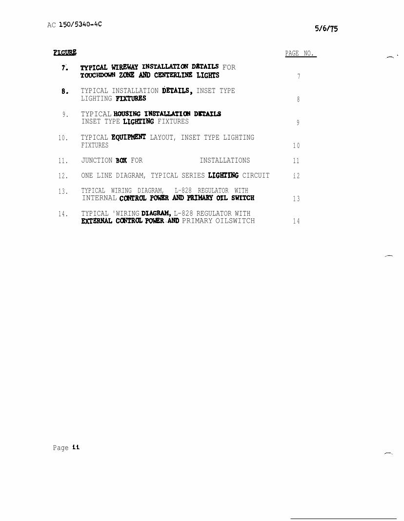
-
AC
PAGE NO
FOR 7
TYPICAL INSTALLATION INSET TYPE LIGHTING 8
9 TYPICAL INSET TYPE FIXTURES 9
10 TYPICAL LAYOUT INSET TYPE LIGHTINGFIXTURES 1 0
11 JUNCTION FOR INSRT FTXTURR INSTALLATIONS 11
12 ONE LINE DIAGRAM TYPICAL SERIES CIRCUIT i 2
13 TYPICAL WIRING DIAGRAM L-828 REGULATOR WITH INTERNAL 13
14 TYPICAL WIRING L-828 REGULATOR WITH PRIMARY OILSWITCH 14
Page
c AC 2
1 INTRODUCTION centerline and touchdown lighting systems are to facilitate landings rollouts and takeoffs The touchshydown Zone light8 are primarily a landing while the centerline
are wed for both landing and takeoff operations
2 CRITERIA Runway centerline lights and touchdown zone lights are required for Category II and Category III runways and for Category Irunway8 used for landing operations below 2400 feet (750 Runway
Runway centerline lights on runwaysfor takeoff below 1600 feet RVR Although
not operationally required runway centerline lights iwe recomnended for I runways greater than 170 feet (50 m) in width or when
by aircraft with approach speeds over 140 knots
3
a Runway Centerline
(1) The lights are located along the runway centerline(15 intervals as shown in Figure 1 The
of lights is offset a maximum of 2 feet to either the right or left side of the runway marking and should be to the
side of the centerline marking from the major taxlwayturnoffs
portion of the lightshying system is color coded to warn pilots of the impendingrunway end Alternate red and white lights are installed asseen from 3000 feet (900 m) to 1000 feet from the runway end and red lights are installed in the last(300 m) portion
srThe last
Displaced On runway8 centerline lights the centerline are extended into the displaced threshold area the displaced area not used for takeoffs or if the displaced area is used is less than 700 feet in length the centerline are blanked out in the direction For displaced threshold areas over700 feet in length and used for takeoffs the centerline lights in the area are circuited separately from the centerline in the nondisplaced runway area to permit
the centerline lights in the displaced areaduring landing operations If the displaced threshold area also contains a medium intensity approach system the controlof the approach lights and displaced threshold area centerline lights are interlocked to insure that when the approach lights are the displaced area centerline lights are and vice
If the displaced threshold area contains a high intenshysity approach lighting system separate circuiting of the censhyterline lights in the displaced area is not required sincethe high approach lights will the center-line lights
Par1
AC CHG 2
b Touchdown Zone Lighting Touchdown zone lights consist of 2 rows of transverse light bars located symmetrically about the runway centershyline as shown in Figure 2 Each light bar consists of 3 unidirectionshyal lights facing the threshold The of light bars extendto a distance of feet or one-half the runway lengthfor runways less than 6000 feet 800 from the threshold with the first light bars located 100 feet from the threshold
4 DESIGN
a eauence of Installation The installation of lights shouldbe done if possible while the runway is under construction or whenan overlay is made This would allow for the installation of L-857 light base and transformer housings with a conduit system which ispreferred Even though lighting may not be programmed at the time ofrunway paving or overlay installation of bases and a conduit systemshould be considered for future installation of inpavement lightingInstallation of the lighting system after paving is verycostly and requires a lengthy shutdown of the runway
b Lavout Provide a design drawing showing the dimensional layoutof the centerline and touchdown zone lighting systems prior toconstruction Correlate this design with current airport drawingsto utilize available ducts and utilities and to avoid conflict with existing or planned facilities
c Runwav Centerline and Touchdown Zone
iampt Fixtures Design these systems for one of theconditions listed below
lsquo(a) In new rigid pavements and new flexible pavements provideaccess to cables and transformers through the use ofconduits and L-857 transformer bases This type ofinstallation will reduce downtime and repair costs when the underground circuits require maintenance SeeFigures 3 and 6
In pavements being overlaid a base and conduit systemas shown in Figures 3 and 6 may be used Thisthe advantages listed in above
In existing pavements provide recesses or holes for thelight-fixtures and shallow sawed for electrical conduc tore This method does not require the installationof bases and conduits See Figure 7
Par 3
AC
(2) Derign 8ach circuit wing 8 for
m with inputof 2400 fixture with 8
To the of current
250 p1U8 1088e8 in to loop
l8CtriC81 lightingOf
high edge control 120 580 8paci81 a8xt p8r8gr8ph
in the control for future 88 8
The load on the of na-exceed the load plur 060 ohm
it not to 8t8y within 8
lt8m drop b8tweex control tower regulator mr8t be con-8t the be 100 Volt8
be either an be
or 8 low DC control circuit be
Of 8 low control circuit the drop within
with the 120
uiDMaat covered by are referred circular
oil u rfyLf rampamp
other of electrical not covered byAviation
to the of electric81
Page 3P u 4
AC
b Light Fixtutee
Provide runway centerline light fixture8 that conform to
Provide light that conformto AC L-8S0 B (Unidirectional)
Provide 2000watt inrrulating (L-844) that to the of AC and
insulating that conform to The treneformer8 8erve a8 a of the light unit from the high voltage of the circuit a filamant opeae the continuity of circuit maintained by the
ing traorrformr
d and Where required provide L-857bare8 that conform to the requirement8 of The
of a cylindrical body with topand cable entrance an internal grounding lug may be
by the The intUMl lug ir ured where interconnected the duct and the ground wire ir inrtalled
through the duct Certain application8 may require addishytional entrance hub8 Provide cover8 a8 in AC
Rwide L-828 current regulator8 thatconformto the of AC The regulatorfor atep control without interrupting load current
ha8 lightning circuit and overcurrent protective a local control are
wired at the factory a8 a are required but are not with the regulator
various rating8 are available
f Control Panel ba in the control if 8pace i8 available provide an L-821
that to of AC The panel of a top plate and
toggle 8titche8 terminal and bright-88a8 required The of the panel and the of
on the for each lightning prevalent lightning
my be the point8 of thtr panal
Auxiliarv Relay Cabinet auxiliary relay cabinetmanufactured in uce with AC can be for
a DC control circuit protection
Page 4 Par S
LI
AC 1
and 20 pilot
cabinet
h Cable Cable the circuit shsll be single( =8AwO insulation
far direct earthburialTgpeB orCln accordance cable for VAC control
A C
the choose to the med Acceptablesubstitutes are cables to Cable
S-66-524 for the c cables and B cables Cables
sawed cuts In
stranded type
or
Connects Rovlde L-823 camectar64zo the cables rhesoc-arsccni~totharequlrementsof AC Use lnstallatlm In for the 10 to the centerllneandtaampdum 6-e leads
Provldeplastlc AC Item L-108
k and AC
1 Concrete AC Item P-501
AC III or and
Federal
Seal a Use described
Select exceed
Par 5 5
AC
Inset Fixtures Fixtures are held in with Item P-606 material liquid and paste
(3) Joints Use joint sealing material conforming to Item P-605across rigid joints
6
a General This section installation methods and techniquesOther methods and techniques and variations of those outlined heremay be used provided they are approved by the appropriate FAA AirportsDistrict Office Correct placement of the lights is of primeimportance to achieve this careful attention to detail is requiredThe light beam must be aligned parallel to the centerline of therunway with a tolerance of The lighting fixture mustbe level and the top of the fixture edge must be between +0and inch from the pavement top see Figure 2 for applicationof tolerance on sections To achieve this result the light base whether in one piece or in sections must be alignedand held in place with jigs until finally secured This method ofinstallation requires surveying that is precise The installation
be with utmost care to avoid remedial action which is verycostly
b Transformer Base (L-857) and Conduit System
(1) New Rigid Pavement This system is preferred but requires careshyful attention to detail during installation of two conditions will be encountered during installation the edge ofexisting pavement available a reference for the new bases or no existing edge is available and bases be set space The availability of an existing pavement edgesimplifies the task of locating the light base in both cases a jig or fixture is required to hold the base inposition while the concrete anchor is placed See Figures 4 and5 Elevation of the base with respect to the runway surface andazimuth with respect to the centerline are two parameters that must be met It is absolutely necessary that the elevation ofthe flange be at least three-quarters of an inch below the pavement surface If less than three-quarters of an inchis left after paving the lighting fixture will be unacceptablyhigh If more than three-quarters of an inch is left adapterrings can be used to bring the lighting fixtures up to the correctelevation Spacers and adapter rings are basically shims and canbe used to bring the lighting fixture to the correct elevationAt each light location make an excavation in the runway base which is large enough to accommodate the light base thereinforcing steel cage and concrete for the anchor After the
Par 5Page 6
AC
excavation is completed light base and steel held in place with the jig See Figure
The jig will establish the elevation and azimuth of thebase and this position the concrete and anchor
placed practice is to each to the system with a length of liquid tight flexibleconduit as in 3 Flexible conduit will allow
in light base before the concrete anchor is placed must be taken while placing the concrete anchorthat neither the jig nor the light bese alignumnt is disturbed The jig Bust remaia place the concrete has set Duringpaving operations the be fitted with a steel cover plate (mud plate) See Figure After the paving trainhas cleared the light base excess concrete from the top
the base and the edge of the around the base should be to a radius The surface of the pavementaround the light base must be level with the surrounding paveshyment dished and mound areas are acceptable After the
has hardened check the elevation of the top flange inrelation to the finished surface It be necessary toinstall a flange ring or flange and spacer ring to bring the light fixture to correct elevation Next install primary cable
and connectors Connect lighting fixture tosecondary cable Install ring gasket and torquebolts to manufacturers the pavingique utiliees more than one of the paving machine the above procedure is altered as follows a sectional light base isrequired after the bottom sectioa has been installed as described above the first pass is The flange isthen cleaned and the next section is with a sealant equal to as Electric Companybetween flanges and in place The paving proceedsand the fixture is installed as above Base and conduit systemsare subject to water intrusion A well-designed system will beequipped with drains at the low
(2) New Pavement A sectional base is required for flexshyible pavement The bottom sectioa of the light base (includingconcrete anchor) and the conduit system are installed in the runway base as described in the preceding paragraph It isthen paved over The light base concrete anchor and conduit
be higher than the base surface After the paving is completed a hole is bored to accuratelylocate the center punch mark of the bottom section cover plateThis hole is used to the actual distance from the topof the pavement to the top of plate An extension
of an inch less than the distance from the pave-at to the top of the plate should be obtained Also obtain a three-quarter-inch flange ring toallow for future adjustment of elevation When
Page 7
AC
- the extension is received a hole one-half inch larger than the diameter of the light should be drilled and the extensionflange ring and light fixture installed as described above The space between the walls of the hole up to the top ofthe adapter ring should be filled with liquid P-606 sealantSee Figure 6
Flexible Overlay The installation of a light base and conduitsystem in a pavement to be overlaid similar to that of a new flexible pavement except the bottom section of the lightbase and the conduit are set in openings made in the existing pavement The anchor and encasement of the conduit will be similar to that described in (2) New Flexible Pavement The use of a short length of liquid tight flexible conduit necessary to allow proper alignment The of the installation as described in the preceding paragraph
Overlay The installation of a lighting base and conduitsystem require8 acomblnation of techniques outlined inpreceding sections of (1) New Rigid Pavement and (3) FlexibleOverlay The base and conduit are installed as in (3) concrete is placed as in (1)
C Inset Installation
(1) Rigid Pavements Drill holes or recesses in the pavements to the light fixtures Saw to accommodate electrical circuits See typical installation details in Figure8 7 8 and
(a) Pavement Drilling and Sawing Provide appraPrimately l4shyinch clearance for sealer material between the bottom and side of the lneet base receptacle and the recessProvide extra depth where sawed wlreways cross pavement joints See Figure 7 for detail
ght Fixtures Install centerline lights to follow the longitudinal contour Place touchdown zone lights level a horizontal plane Unless otherwise epeclfied the tolerance for being level is
Figure 2
Rlor torsquoplacing the inset base receptacle in the drilledhole clean all external surfaces to assure an adequatebond between fixture sealer and pavement Sand blast if necessary Avoid handling the fixtures by the leads
15053404c CHC 1
Orientate the fixture rrmgethe leedrrsquoproperly with to their in the
temporary if required for blocking the entrance the drilled hole The will retain the realer during of the bare receptacleThe for the bare a line parallel with the rummy centerline
are 88ura proper azimuth levetioa and level
Cover the bottom of the receptacle with 6 paateshytype dhe8Fve material Place a quantity of
in tha hole Place the bare in the drilled hole to force the of the at least
inch be taken to work out entrapped air a liquid (paragraph fill the between
the bare of the hole Liquid rearer 8hould be ppliedonly between the-iaret b88e regeptacle and the
of the hole not be applied the Of the hole and the top 888emb1y
to the of the wires in the pavement chamfer or to -inch radiur vertical
of the at and See Figure 10 clean to properbond between pavement material and the If
have been there with a velocity of after sawing to of the
bedryandclean
(d) Wirer place the lo THWN in th wirewaye from ormarr near the runway edge to the light fixture
an number (3 feet on of or device8 to hold the wires in place at least one-half of an inch below the payment 6urshy
wedge8 are not acceptablethe top of the wedge8 below the pavement Splicethe light fixture lead8 to the lO THWN wirer Use pre-
Make the crimped with a tool that require6 a complete crimp before
the Of the Permit no the conductor except at each light If
the in tape or real the of wire8 to prevent the of moisture Seal in the with P-606 Apply in with AC aad the followins
Page 9Par
_
AC --
Pour sealer in until surface of wire covered
If by the manufacturer pour clean eand into the liquid until a alight smountof sand on the Use clean sand that through a Number40
Fill the remainder of the to pavement level withliquid sealer but in case above pavement level
Sealer material extending above pavement surface be removed
Pavement Install light fixtures and wires flexshyible ilar to the procedures in rigid
with the following precautions
lean the holes and before 80 the dry aggregate of the pavement Fe
exposed
(for on fixtures) so that15 minutes
sealant conform8 to P-606 or Specification E-2373 to real wires in
be installed on runways where See 10 When additional
the inset light removed and the bare is fitted with cover paving then applied lightbase and junction box When the paving is completed
the junction box and light bare by coring RemoveAdd to the junction box and light
bare cover box and on bare
d Vault
(2) Exercise campe while working the vault to preventiron stripping or other foreign
collecting on switches and otherCollect and remove all residue as the
Use cover8 or shields during installashytion wiring protect component8 from foreign matter
in accordance with
10 Par 6
Cable Cable shall be in accordance with L-108Advisory Circular In the event of a conflict between
paragraph L-108 this shell govern Providesufficient slack to enable primary cable connections to beabove ground be splices the cable
light Connections of cable to shall be made with L-823 cable the
primary are taped secondary connections not rubber tape by plastic where connector and cable joinedUse only tape where the two halves cable ends if connections not made
7
8 Conduit Inspection and testing of lightingduring ionare important Certain components
be for corrective action after the final installation
Inspect the installed light to if the has been installed in accordance with the instructions and at the proper elevation
Check the alignment of all units to determine if lightingfixtures have been installed in accordance with design and
Check the fixtures and bases to determine if the securinghardware has been tightened in accordance with the
instructions
inspect the lighting fixture8 to determine if the lenser 8nd channels in front of the are clean
Tart vault equipment and circuit8 in AC L-109 and L-108 respectively
Measure and record all operating voltage8 and currents and insulation resistance
b Inset In addition to the above perform the inspection and for these lights concurrently with the because
of -inaccessibility of soxs coxponents ampfore fillingwireways identify and test the secondary series circuit for each
of runway for continuity and insulation to ground Check the insulation 8 (minimum)insul8tion resirtmce tester An acceptable circuit ha8 aof least so After fixtures and wirer are perform a inspection of the sealer in the and around the fixture8 to determine if 811 voids are filled and that is at the proper level with respect to the surface After these
Par 6rsquo Page 11
AC
tests have been performed and the lighting circuits are completedtest the system by continuous operation for a period of not lessthan one-half hour prior to acceptance The tests include the operation of each control not less than 10 times
a
a General Establish a maintenance program at airports where centershyline and touchdown zone lights are installed to insure properoperation and dependable service from the equipment The effectiveshyness of a will soon depreciate unless it is properlytained Maintenance recommendations are contained in AdvisoryCircular Maintenance Guide for Determiningand Cleaning of Centerline and Touchdown Zone Lights
(1) Perform a daily operational check of all lighting fixturesthe runway centerline and touchdown zone lights and
visually inspect the light output If any lamps are out orfixtures are obscured record the location of the fixtures and replace the lamps or top fittings containing the opticallenses Replace lamps when the circuit is deactivated
(2) Clean the lighting fixtures regularly so that the system canmeet performance requirements for low visibility conditionsClean the lens and channel in front of the lens periodically
in accordance with manufacturers recommendations The regularity and type of cleaning will be dictated by the weatherconditions and the location of the fixtures
(3) Snow should be removed from around the lights with powerbroom if practical If it becomes necessary for snowplows to cross lights it is recommended that the blade be lifted
as a last resort should the blade be allowed to come in contact with the light Rubber and plastic-edge snowplowblades are that are especially suited for plowing wet or slushy snow snow removal techniques arecontained in AC
b
(1) Replacement Group replacement may be beneficial and should belsquoconsidered It is that lamps be replaced when the number hours of operation on top brightness stepequals the lamps rated ltfe
(2) Deenergite the circuit supplying the fixturecontaining the burned-out lamp Remove the top assembly A
practice is to replace the complete top assembly and subsequently it in a clean indoor location Replace the seals if they appear to be worn or damaged Beforethe top assembly is replaced clean and dry the unit Properly
Par 7Page 12
3
C
d
Par
AC
position seat all gaskets Tighten all screws bolts or other securing hardware in accordance with manufacturerrsquos
(If fixture8 are not properly secured theymight be damaged by normal aircraft
Removal of Water The lighting fixtures are designed to excludeboth ground and surface water from entering water someshytimes enters and becomes a serious problem particularly wherefreezing temperatures are encountered If the barer or receptaclesfill withlsquowater freezing cause damage to the fixture byshearing the top assembly hardware or rupturing the base or receptacle To prevent this establish a regular schedule forremoving water especially during the fall and winter monthsEstablish a regular schedule for tightening cover bolts If any of the fixtures contain water remove this water and clean and dry the receptacle lamp and electrical contacts Properlyposition andor seat all and tighten the hardware securingthe top assembly in accordance with the instructions
Cable Check home runs of cables with a (minimum) insulashytion resistance tester before the installation been accepted
records of the resistance values obtained In order to check the condition of the system compare periodic reading6 with theinitial values In an acceptable system the initial insulationresistance value is not less than 50 and much higher (in the order of hundreds of megohms) If the periodicchecks reveal progressive deterioration or faults take steps promptly
(1) Make periodic insulation checks by first the regulator Monthly checks are Open the series disconnects Connect one lead of the insulation
to the load side of one disconnect connect the other lead to a proven ground Operate the test equipment inaccordance with instrument
(2) Maintenance personnel must be that high open-circuitvoltage is present when the secondary of an constant current regulator opened Troublerhooting is complicated by the fact that in instances the interconnecting wiresare sealed in the runway pavement8 and the fixtures are located in an active part of the runway For this reason itis important to check the system during the installation and to establish an effective preventive maintenance program
Page 13
AC
Spare Parts The importance of stocking spare parts cannot be overemphasized Spare example should be procured whenthe lighting system into Operation and when the begin indicates that frantic requests for
delivery of replacement lamps often cannot be met by thesupplier Replaceable parts of fixtures and replaceable componentsof regulators should also be stocked for maintenance purposes
Vault Keep the vault (AC Item L-109) uncluttered toprevent dirt from accumulating in control compartmenta and to allowequipment to be accessible at Mount legible warning
in conapicious places Make periodic checks of supply voltage and output current
Test To the light Of inpavement lightingobtain the equipment described in AC Maintenance Guide for Determining Degradation and Cleaning of Centerline and Touchshydown Zone Lights In addition the following equipment is recomshymended
(minimum) insulation resistance testerVolt-ohm meter and clamp-on ammeterRubber safetyHot stick
Other test equipment as required by a particular
ParPage 14
AC 1
1 ( A C ) F e d e r a l
cl2malarr and thereto It axplains the
sale well free AC also
(1) AC and Statue cb Regulatlau3~
(2) AC for and Alz3iortr Dbltrlct
(3) AC 1505$b619 Taxlway
(4) AC Maintenance Guldt
AC for L-821 Alrpti Llghtlq Panel
(6) AC Electrical Cables
for ~cntstant current
(8) AC for L-841 far Pilot of
for andReceptacle
(10) AC FM 6857~1~-pe LQht
AC for
for Airport Llghtlng
(13) AC Removal ar8
1 AC 1 Appendix 1
b latest Issuance of AC Standards for SpecifyingAirports can be In AC be
obtained from the Superintendent of Documents US Office Washiagton DC
copies of Eleckrlficatian AdministratIon Bulletin for Telephmo Cables and
Bulletin for CablesUS
Washington
Cbtaln copies of (ASG)Power Series Airport Liamphtinamp General
Office EavalSupply Depot 5901 Avenue Philadelphia Pennsylvania Attention Code
4 copies of FAA-E-2373 Adhesive for Sealing Wire in Pavements
Configuration Branch IndependenceAvenue SW Waehingtoa DC 20591
5 IFCEA Publlcatlons S-66-524 of
Electrical Energy and Ribber-insulated and Cable for the and af ElectrIcal Energy be obtained
the Electrical 155
Par 1
-
-
touchdown per
0 centerline
bbI whit
r o w - white red
Conterlinr light8 2rsquo to the or left of runwoy lo avoid the centerline paint
2 Thr crntorlinr l i g h t s m a y 0 o f o o f
3 The 3000 foot 1000 foot of runwoy on alternate and light rignol
4 foot of runwoy on rod signal
touchdown light bon not required to locotrd at thr 2 f o r
1 RUNWAY LIGHTING LAYOUT
S9 NVHL I O N 0 1
3 8
V N I
- - - - -
o f
-
~
BASE VARIES
AR
BASE AND OR SUBBASE
ANCHOR
3 SECTION THROUGH BASE AND ANCHOR BASE AND
AC 1 Appendix 2
JIG FOR ALIGNING BASE I
PC CONCRETE ANCHOR
AOJUSTABLE BAR CAGE
SUBBASE
NOTE
COVER PLATE SHOWN FOR ILLUSTRATION ONLY USE OF MUD PLATES CONSTRUCTION RINGS EXTENSIONS ON PAVING
Page 4
rsquo
1
PAVEMENTshy
PLATE SHOWN FOR ONLY USE MUD PLATES RINGS ON
I
L-550 FIXTURE
L-057 BASE
ASPHALT
BASE AND OR L- 555ASE
VARIES
f
VARIES
)
pnee
FIGURE
I2W Itmiddot
bullc-c middot---middot
NL bull
r n-
)
=n
011 bull fll --
- lfiiCifle1 bull ~ __ ltllt_ _ - - -_
bull _ OttbullY __ _ Wtrbull
INSTAIIATIW pErAILS FOil ToucHDOWN ZONE AND CENTERLINE LlGJflS
7 TYPICALWIREWAY
--
-
-
and
JOINT
DE TAIL
NOTES
w i r e s l e s s t h a n below sea t compound s e e S e c t i o n s A A and f o r d i m e n s i o n s
2 d i m e n s i o n s o f cored hole f o r - 8 5 0 f i x t u r e D e p t h
8 TYPICAL INSTALLATUJN DETAILS INSET LIGHTING FIXTURES
-
Appendix 2
HOUSING INSTALLATION
C U L L
SECTION 0
ARE INSTALLED IN WITH L-106
STANDARDS FOR OF
CONNECTORS-NUMBERS REFER TO L
NUMBERS
TYPICAL XTKES - - -
0 Awe
TRANSFORMER CONNECTIONS
01 3lUl3Id
and fobficote bon IO t h e f o o d i n speciftcaiti L- 850
Fill junction bon with o j u n c t i o n b o x l e v e l w i t h t h ei s t o prevenl waler f r o m h fhe junction b o r
t h e bar and t o oermit ins~ollotion amp v i c eProvide o ond grommets lo
b o a
FIGURE 11 JUNCTION BOX FOR INSET FIXTURE INSTALLATIONS
rsquo
lsquo
l
REGULATOR LOCATED
IN VAULT LIGHTS
W A T l S L - 6 5 0 T Y P E A
L - 8 2 8
SERIES LOOP
CENTERLINE ZONE]
CONSTANT CURRENT
REGULATOR LOCATED IN VAULT I TRANSFORMER L-830
200 WATTS IN L -657 BASE
F IXTURE L-
2 0 0 W T Y P E
TOUCHOOWN ZONE1
LIGHTING FIXTURE 200
12 ONE LINE DIAGRAM SERIES LIGHTING
AC Appendix 2
I
L SrsquoLI-rsquo CONTROL PANEL IN TOWER
L -828
CONTROL 7 C U R R E N T WIRES SEE NOTE S T E P - T Y P E
REGULATOR WITH INTERNAL
PRIMARY OIL
ISW I
I rdquo
I
I
OUTPUT
F U S E D C U T O U T
I
LIGHTNING ARRESTOR
CUTOUT W I T H
REGULATOR)TO RUNWAYNOTE LIGHTING CIRCUIT
C I R C U I T U P A P P R O X 3 0 0 0 O R
D R O P I S N O T D R O P I S I N O R A T CORTROI TERYIRALLOU C O N T R O L S E U S E D
13 WIampG REGULATOR WITH CONTROL AND SWITCH
13
AC
NOTES
AS A ELECTRICAL INSTALLATION CONFORM TO APPLICABLE SECTIONS OF THE NATIONAL ELECTRICAL CODE
PANEL TOWER
REMOTE OIL SWITCH
H2 INPUT
L - 8 2 8 CONSTANT CURRENT STEP TYPE
WITH EXTERNAL PRIMARY OIL
SWITCH
O U T P U T
ARRESTOR SEE NOTE 4
LIGHTNING ARRESTOR SEE NOTE4
7 WIRES SEE NOTE
AND CODES
2 MAY SE USED SEE NOTE I FIGURE
WHEN COUNTERPOISE IS IT INSTALLED IN ACCORDANCE WITH ITEM OF STANDARDS FOR SPECIFYING CONSTRUCTION OF AIRPORTS
4 ARRESTORS FURNISHED REGULATOR
FUSED CUTOUT-
14 TYPICAL REGULATOR WITH CONTROL POWER MD PRIMARY OIL SWITCH
AC
b Light Fixtutee
Provide runway centerline light fixture8 that conform to
Provide light that conformto AC L-8S0 B (Unidirectional)
Provide 2000watt inrrulating (L-844) that to the of AC and
insulating that conform to The treneformer8 8erve a8 a of the light unit from the high voltage of the circuit a filamant opeae the continuity of circuit maintained by the
ing traorrformr
d and Where required provide L-857bare8 that conform to the requirement8 of The
of a cylindrical body with topand cable entrance an internal grounding lug may be
by the The intUMl lug ir ured where interconnected the duct and the ground wire ir inrtalled
through the duct Certain application8 may require addishytional entrance hub8 Provide cover8 a8 in AC
Rwide L-828 current regulator8 thatconformto the of AC The regulatorfor atep control without interrupting load current
ha8 lightning circuit and overcurrent protective a local control are
wired at the factory a8 a are required but are not with the regulator
various rating8 are available
f Control Panel ba in the control if 8pace i8 available provide an L-821
that to of AC The panel of a top plate and
toggle 8titche8 terminal and bright-88a8 required The of the panel and the of
on the for each lightning prevalent lightning
my be the point8 of thtr panal
Auxiliarv Relay Cabinet auxiliary relay cabinetmanufactured in uce with AC can be for
a DC control circuit protection
Page 4 Par S
LI
AC 1
and 20 pilot
cabinet
h Cable Cable the circuit shsll be single( =8AwO insulation
far direct earthburialTgpeB orCln accordance cable for VAC control
A C
the choose to the med Acceptablesubstitutes are cables to Cable
S-66-524 for the c cables and B cables Cables
sawed cuts In
stranded type
or
Connects Rovlde L-823 camectar64zo the cables rhesoc-arsccni~totharequlrementsof AC Use lnstallatlm In for the 10 to the centerllneandtaampdum 6-e leads
Provldeplastlc AC Item L-108
k and AC
1 Concrete AC Item P-501
AC III or and
Federal
Seal a Use described
Select exceed
Par 5 5
AC
Inset Fixtures Fixtures are held in with Item P-606 material liquid and paste
(3) Joints Use joint sealing material conforming to Item P-605across rigid joints
6
a General This section installation methods and techniquesOther methods and techniques and variations of those outlined heremay be used provided they are approved by the appropriate FAA AirportsDistrict Office Correct placement of the lights is of primeimportance to achieve this careful attention to detail is requiredThe light beam must be aligned parallel to the centerline of therunway with a tolerance of The lighting fixture mustbe level and the top of the fixture edge must be between +0and inch from the pavement top see Figure 2 for applicationof tolerance on sections To achieve this result the light base whether in one piece or in sections must be alignedand held in place with jigs until finally secured This method ofinstallation requires surveying that is precise The installation
be with utmost care to avoid remedial action which is verycostly
b Transformer Base (L-857) and Conduit System
(1) New Rigid Pavement This system is preferred but requires careshyful attention to detail during installation of two conditions will be encountered during installation the edge ofexisting pavement available a reference for the new bases or no existing edge is available and bases be set space The availability of an existing pavement edgesimplifies the task of locating the light base in both cases a jig or fixture is required to hold the base inposition while the concrete anchor is placed See Figures 4 and5 Elevation of the base with respect to the runway surface andazimuth with respect to the centerline are two parameters that must be met It is absolutely necessary that the elevation ofthe flange be at least three-quarters of an inch below the pavement surface If less than three-quarters of an inchis left after paving the lighting fixture will be unacceptablyhigh If more than three-quarters of an inch is left adapterrings can be used to bring the lighting fixtures up to the correctelevation Spacers and adapter rings are basically shims and canbe used to bring the lighting fixture to the correct elevationAt each light location make an excavation in the runway base which is large enough to accommodate the light base thereinforcing steel cage and concrete for the anchor After the
Par 5Page 6
AC
excavation is completed light base and steel held in place with the jig See Figure
The jig will establish the elevation and azimuth of thebase and this position the concrete and anchor
placed practice is to each to the system with a length of liquid tight flexibleconduit as in 3 Flexible conduit will allow
in light base before the concrete anchor is placed must be taken while placing the concrete anchorthat neither the jig nor the light bese alignumnt is disturbed The jig Bust remaia place the concrete has set Duringpaving operations the be fitted with a steel cover plate (mud plate) See Figure After the paving trainhas cleared the light base excess concrete from the top
the base and the edge of the around the base should be to a radius The surface of the pavementaround the light base must be level with the surrounding paveshyment dished and mound areas are acceptable After the
has hardened check the elevation of the top flange inrelation to the finished surface It be necessary toinstall a flange ring or flange and spacer ring to bring the light fixture to correct elevation Next install primary cable
and connectors Connect lighting fixture tosecondary cable Install ring gasket and torquebolts to manufacturers the pavingique utiliees more than one of the paving machine the above procedure is altered as follows a sectional light base isrequired after the bottom sectioa has been installed as described above the first pass is The flange isthen cleaned and the next section is with a sealant equal to as Electric Companybetween flanges and in place The paving proceedsand the fixture is installed as above Base and conduit systemsare subject to water intrusion A well-designed system will beequipped with drains at the low
(2) New Pavement A sectional base is required for flexshyible pavement The bottom sectioa of the light base (includingconcrete anchor) and the conduit system are installed in the runway base as described in the preceding paragraph It isthen paved over The light base concrete anchor and conduit
be higher than the base surface After the paving is completed a hole is bored to accuratelylocate the center punch mark of the bottom section cover plateThis hole is used to the actual distance from the topof the pavement to the top of plate An extension
of an inch less than the distance from the pave-at to the top of the plate should be obtained Also obtain a three-quarter-inch flange ring toallow for future adjustment of elevation When
Page 7
AC
- the extension is received a hole one-half inch larger than the diameter of the light should be drilled and the extensionflange ring and light fixture installed as described above The space between the walls of the hole up to the top ofthe adapter ring should be filled with liquid P-606 sealantSee Figure 6
Flexible Overlay The installation of a light base and conduitsystem in a pavement to be overlaid similar to that of a new flexible pavement except the bottom section of the lightbase and the conduit are set in openings made in the existing pavement The anchor and encasement of the conduit will be similar to that described in (2) New Flexible Pavement The use of a short length of liquid tight flexible conduit necessary to allow proper alignment The of the installation as described in the preceding paragraph
Overlay The installation of a lighting base and conduitsystem require8 acomblnation of techniques outlined inpreceding sections of (1) New Rigid Pavement and (3) FlexibleOverlay The base and conduit are installed as in (3) concrete is placed as in (1)
C Inset Installation
(1) Rigid Pavements Drill holes or recesses in the pavements to the light fixtures Saw to accommodate electrical circuits See typical installation details in Figure8 7 8 and
(a) Pavement Drilling and Sawing Provide appraPrimately l4shyinch clearance for sealer material between the bottom and side of the lneet base receptacle and the recessProvide extra depth where sawed wlreways cross pavement joints See Figure 7 for detail
ght Fixtures Install centerline lights to follow the longitudinal contour Place touchdown zone lights level a horizontal plane Unless otherwise epeclfied the tolerance for being level is
Figure 2
Rlor torsquoplacing the inset base receptacle in the drilledhole clean all external surfaces to assure an adequatebond between fixture sealer and pavement Sand blast if necessary Avoid handling the fixtures by the leads
15053404c CHC 1
Orientate the fixture rrmgethe leedrrsquoproperly with to their in the
temporary if required for blocking the entrance the drilled hole The will retain the realer during of the bare receptacleThe for the bare a line parallel with the rummy centerline
are 88ura proper azimuth levetioa and level
Cover the bottom of the receptacle with 6 paateshytype dhe8Fve material Place a quantity of
in tha hole Place the bare in the drilled hole to force the of the at least
inch be taken to work out entrapped air a liquid (paragraph fill the between
the bare of the hole Liquid rearer 8hould be ppliedonly between the-iaret b88e regeptacle and the
of the hole not be applied the Of the hole and the top 888emb1y
to the of the wires in the pavement chamfer or to -inch radiur vertical
of the at and See Figure 10 clean to properbond between pavement material and the If
have been there with a velocity of after sawing to of the
bedryandclean
(d) Wirer place the lo THWN in th wirewaye from ormarr near the runway edge to the light fixture
an number (3 feet on of or device8 to hold the wires in place at least one-half of an inch below the payment 6urshy
wedge8 are not acceptablethe top of the wedge8 below the pavement Splicethe light fixture lead8 to the lO THWN wirer Use pre-
Make the crimped with a tool that require6 a complete crimp before
the Of the Permit no the conductor except at each light If
the in tape or real the of wire8 to prevent the of moisture Seal in the with P-606 Apply in with AC aad the followins
Page 9Par
_
AC --
Pour sealer in until surface of wire covered
If by the manufacturer pour clean eand into the liquid until a alight smountof sand on the Use clean sand that through a Number40
Fill the remainder of the to pavement level withliquid sealer but in case above pavement level
Sealer material extending above pavement surface be removed
Pavement Install light fixtures and wires flexshyible ilar to the procedures in rigid
with the following precautions
lean the holes and before 80 the dry aggregate of the pavement Fe
exposed
(for on fixtures) so that15 minutes
sealant conform8 to P-606 or Specification E-2373 to real wires in
be installed on runways where See 10 When additional
the inset light removed and the bare is fitted with cover paving then applied lightbase and junction box When the paving is completed
the junction box and light bare by coring RemoveAdd to the junction box and light
bare cover box and on bare
d Vault
(2) Exercise campe while working the vault to preventiron stripping or other foreign
collecting on switches and otherCollect and remove all residue as the
Use cover8 or shields during installashytion wiring protect component8 from foreign matter
in accordance with
10 Par 6
Cable Cable shall be in accordance with L-108Advisory Circular In the event of a conflict between
paragraph L-108 this shell govern Providesufficient slack to enable primary cable connections to beabove ground be splices the cable
light Connections of cable to shall be made with L-823 cable the
primary are taped secondary connections not rubber tape by plastic where connector and cable joinedUse only tape where the two halves cable ends if connections not made
7
8 Conduit Inspection and testing of lightingduring ionare important Certain components
be for corrective action after the final installation
Inspect the installed light to if the has been installed in accordance with the instructions and at the proper elevation
Check the alignment of all units to determine if lightingfixtures have been installed in accordance with design and
Check the fixtures and bases to determine if the securinghardware has been tightened in accordance with the
instructions
inspect the lighting fixture8 to determine if the lenser 8nd channels in front of the are clean
Tart vault equipment and circuit8 in AC L-109 and L-108 respectively
Measure and record all operating voltage8 and currents and insulation resistance
b Inset In addition to the above perform the inspection and for these lights concurrently with the because
of -inaccessibility of soxs coxponents ampfore fillingwireways identify and test the secondary series circuit for each
of runway for continuity and insulation to ground Check the insulation 8 (minimum)insul8tion resirtmce tester An acceptable circuit ha8 aof least so After fixtures and wirer are perform a inspection of the sealer in the and around the fixture8 to determine if 811 voids are filled and that is at the proper level with respect to the surface After these
Par 6rsquo Page 11
AC
tests have been performed and the lighting circuits are completedtest the system by continuous operation for a period of not lessthan one-half hour prior to acceptance The tests include the operation of each control not less than 10 times
a
a General Establish a maintenance program at airports where centershyline and touchdown zone lights are installed to insure properoperation and dependable service from the equipment The effectiveshyness of a will soon depreciate unless it is properlytained Maintenance recommendations are contained in AdvisoryCircular Maintenance Guide for Determiningand Cleaning of Centerline and Touchdown Zone Lights
(1) Perform a daily operational check of all lighting fixturesthe runway centerline and touchdown zone lights and
visually inspect the light output If any lamps are out orfixtures are obscured record the location of the fixtures and replace the lamps or top fittings containing the opticallenses Replace lamps when the circuit is deactivated
(2) Clean the lighting fixtures regularly so that the system canmeet performance requirements for low visibility conditionsClean the lens and channel in front of the lens periodically
in accordance with manufacturers recommendations The regularity and type of cleaning will be dictated by the weatherconditions and the location of the fixtures
(3) Snow should be removed from around the lights with powerbroom if practical If it becomes necessary for snowplows to cross lights it is recommended that the blade be lifted
as a last resort should the blade be allowed to come in contact with the light Rubber and plastic-edge snowplowblades are that are especially suited for plowing wet or slushy snow snow removal techniques arecontained in AC
b
(1) Replacement Group replacement may be beneficial and should belsquoconsidered It is that lamps be replaced when the number hours of operation on top brightness stepequals the lamps rated ltfe
(2) Deenergite the circuit supplying the fixturecontaining the burned-out lamp Remove the top assembly A
practice is to replace the complete top assembly and subsequently it in a clean indoor location Replace the seals if they appear to be worn or damaged Beforethe top assembly is replaced clean and dry the unit Properly
Par 7Page 12
3
C
d
Par
AC
position seat all gaskets Tighten all screws bolts or other securing hardware in accordance with manufacturerrsquos
(If fixture8 are not properly secured theymight be damaged by normal aircraft
Removal of Water The lighting fixtures are designed to excludeboth ground and surface water from entering water someshytimes enters and becomes a serious problem particularly wherefreezing temperatures are encountered If the barer or receptaclesfill withlsquowater freezing cause damage to the fixture byshearing the top assembly hardware or rupturing the base or receptacle To prevent this establish a regular schedule forremoving water especially during the fall and winter monthsEstablish a regular schedule for tightening cover bolts If any of the fixtures contain water remove this water and clean and dry the receptacle lamp and electrical contacts Properlyposition andor seat all and tighten the hardware securingthe top assembly in accordance with the instructions
Cable Check home runs of cables with a (minimum) insulashytion resistance tester before the installation been accepted
records of the resistance values obtained In order to check the condition of the system compare periodic reading6 with theinitial values In an acceptable system the initial insulationresistance value is not less than 50 and much higher (in the order of hundreds of megohms) If the periodicchecks reveal progressive deterioration or faults take steps promptly
(1) Make periodic insulation checks by first the regulator Monthly checks are Open the series disconnects Connect one lead of the insulation
to the load side of one disconnect connect the other lead to a proven ground Operate the test equipment inaccordance with instrument
(2) Maintenance personnel must be that high open-circuitvoltage is present when the secondary of an constant current regulator opened Troublerhooting is complicated by the fact that in instances the interconnecting wiresare sealed in the runway pavement8 and the fixtures are located in an active part of the runway For this reason itis important to check the system during the installation and to establish an effective preventive maintenance program
Page 13
AC
Spare Parts The importance of stocking spare parts cannot be overemphasized Spare example should be procured whenthe lighting system into Operation and when the begin indicates that frantic requests for
delivery of replacement lamps often cannot be met by thesupplier Replaceable parts of fixtures and replaceable componentsof regulators should also be stocked for maintenance purposes
Vault Keep the vault (AC Item L-109) uncluttered toprevent dirt from accumulating in control compartmenta and to allowequipment to be accessible at Mount legible warning
in conapicious places Make periodic checks of supply voltage and output current
Test To the light Of inpavement lightingobtain the equipment described in AC Maintenance Guide for Determining Degradation and Cleaning of Centerline and Touchshydown Zone Lights In addition the following equipment is recomshymended
(minimum) insulation resistance testerVolt-ohm meter and clamp-on ammeterRubber safetyHot stick
Other test equipment as required by a particular
ParPage 14
AC 1
1 ( A C ) F e d e r a l
cl2malarr and thereto It axplains the
sale well free AC also
(1) AC and Statue cb Regulatlau3~
(2) AC for and Alz3iortr Dbltrlct
(3) AC 1505$b619 Taxlway
(4) AC Maintenance Guldt
AC for L-821 Alrpti Llghtlq Panel
(6) AC Electrical Cables
for ~cntstant current
(8) AC for L-841 far Pilot of
for andReceptacle
(10) AC FM 6857~1~-pe LQht
AC for
for Airport Llghtlng
(13) AC Removal ar8
1 AC 1 Appendix 1
b latest Issuance of AC Standards for SpecifyingAirports can be In AC be
obtained from the Superintendent of Documents US Office Washiagton DC
copies of Eleckrlficatian AdministratIon Bulletin for Telephmo Cables and
Bulletin for CablesUS
Washington
Cbtaln copies of (ASG)Power Series Airport Liamphtinamp General
Office EavalSupply Depot 5901 Avenue Philadelphia Pennsylvania Attention Code
4 copies of FAA-E-2373 Adhesive for Sealing Wire in Pavements
Configuration Branch IndependenceAvenue SW Waehingtoa DC 20591
5 IFCEA Publlcatlons S-66-524 of
Electrical Energy and Ribber-insulated and Cable for the and af ElectrIcal Energy be obtained
the Electrical 155
Par 1
-
-
touchdown per
0 centerline
bbI whit
r o w - white red
Conterlinr light8 2rsquo to the or left of runwoy lo avoid the centerline paint
2 Thr crntorlinr l i g h t s m a y 0 o f o o f
3 The 3000 foot 1000 foot of runwoy on alternate and light rignol
4 foot of runwoy on rod signal
touchdown light bon not required to locotrd at thr 2 f o r
1 RUNWAY LIGHTING LAYOUT
S9 NVHL I O N 0 1
3 8
V N I
- - - - -
o f
-
~
BASE VARIES
AR
BASE AND OR SUBBASE
ANCHOR
3 SECTION THROUGH BASE AND ANCHOR BASE AND
AC 1 Appendix 2
JIG FOR ALIGNING BASE I
PC CONCRETE ANCHOR
AOJUSTABLE BAR CAGE
SUBBASE
NOTE
COVER PLATE SHOWN FOR ILLUSTRATION ONLY USE OF MUD PLATES CONSTRUCTION RINGS EXTENSIONS ON PAVING
Page 4
rsquo
1
PAVEMENTshy
PLATE SHOWN FOR ONLY USE MUD PLATES RINGS ON
I
L-550 FIXTURE
L-057 BASE
ASPHALT
BASE AND OR L- 555ASE
VARIES
f
VARIES
)
pnee
FIGURE
I2W Itmiddot
bullc-c middot---middot
NL bull
r n-
)
=n
011 bull fll --
- lfiiCifle1 bull ~ __ ltllt_ _ - - -_
bull _ OttbullY __ _ Wtrbull
INSTAIIATIW pErAILS FOil ToucHDOWN ZONE AND CENTERLINE LlGJflS
7 TYPICALWIREWAY
--
-
-
and
JOINT
DE TAIL
NOTES
w i r e s l e s s t h a n below sea t compound s e e S e c t i o n s A A and f o r d i m e n s i o n s
2 d i m e n s i o n s o f cored hole f o r - 8 5 0 f i x t u r e D e p t h
8 TYPICAL INSTALLATUJN DETAILS INSET LIGHTING FIXTURES
-
Appendix 2
HOUSING INSTALLATION
C U L L
SECTION 0
ARE INSTALLED IN WITH L-106
STANDARDS FOR OF
CONNECTORS-NUMBERS REFER TO L
NUMBERS
TYPICAL XTKES - - -
0 Awe
TRANSFORMER CONNECTIONS
01 3lUl3Id
and fobficote bon IO t h e f o o d i n speciftcaiti L- 850
Fill junction bon with o j u n c t i o n b o x l e v e l w i t h t h ei s t o prevenl waler f r o m h fhe junction b o r
t h e bar and t o oermit ins~ollotion amp v i c eProvide o ond grommets lo
b o a
FIGURE 11 JUNCTION BOX FOR INSET FIXTURE INSTALLATIONS
rsquo
lsquo
l
REGULATOR LOCATED
IN VAULT LIGHTS
W A T l S L - 6 5 0 T Y P E A
L - 8 2 8
SERIES LOOP
CENTERLINE ZONE]
CONSTANT CURRENT
REGULATOR LOCATED IN VAULT I TRANSFORMER L-830
200 WATTS IN L -657 BASE
F IXTURE L-
2 0 0 W T Y P E
TOUCHOOWN ZONE1
LIGHTING FIXTURE 200
12 ONE LINE DIAGRAM SERIES LIGHTING
AC Appendix 2
I
L SrsquoLI-rsquo CONTROL PANEL IN TOWER
L -828
CONTROL 7 C U R R E N T WIRES SEE NOTE S T E P - T Y P E
REGULATOR WITH INTERNAL
PRIMARY OIL
ISW I
I rdquo
I
I
OUTPUT
F U S E D C U T O U T
I
LIGHTNING ARRESTOR
CUTOUT W I T H
REGULATOR)TO RUNWAYNOTE LIGHTING CIRCUIT
C I R C U I T U P A P P R O X 3 0 0 0 O R
D R O P I S N O T D R O P I S I N O R A T CORTROI TERYIRALLOU C O N T R O L S E U S E D
13 WIampG REGULATOR WITH CONTROL AND SWITCH
13
AC
NOTES
AS A ELECTRICAL INSTALLATION CONFORM TO APPLICABLE SECTIONS OF THE NATIONAL ELECTRICAL CODE
PANEL TOWER
REMOTE OIL SWITCH
H2 INPUT
L - 8 2 8 CONSTANT CURRENT STEP TYPE
WITH EXTERNAL PRIMARY OIL
SWITCH
O U T P U T
ARRESTOR SEE NOTE 4
LIGHTNING ARRESTOR SEE NOTE4
7 WIRES SEE NOTE
AND CODES
2 MAY SE USED SEE NOTE I FIGURE
WHEN COUNTERPOISE IS IT INSTALLED IN ACCORDANCE WITH ITEM OF STANDARDS FOR SPECIFYING CONSTRUCTION OF AIRPORTS
4 ARRESTORS FURNISHED REGULATOR
FUSED CUTOUT-
14 TYPICAL REGULATOR WITH CONTROL POWER MD PRIMARY OIL SWITCH
AC
Inset Fixtures Fixtures are held in with Item P-606 material liquid and paste
(3) Joints Use joint sealing material conforming to Item P-605across rigid joints
6
a General This section installation methods and techniquesOther methods and techniques and variations of those outlined heremay be used provided they are approved by the appropriate FAA AirportsDistrict Office Correct placement of the lights is of primeimportance to achieve this careful attention to detail is requiredThe light beam must be aligned parallel to the centerline of therunway with a tolerance of The lighting fixture mustbe level and the top of the fixture edge must be between +0and inch from the pavement top see Figure 2 for applicationof tolerance on sections To achieve this result the light base whether in one piece or in sections must be alignedand held in place with jigs until finally secured This method ofinstallation requires surveying that is precise The installation
be with utmost care to avoid remedial action which is verycostly
b Transformer Base (L-857) and Conduit System
(1) New Rigid Pavement This system is preferred but requires careshyful attention to detail during installation of two conditions will be encountered during installation the edge ofexisting pavement available a reference for the new bases or no existing edge is available and bases be set space The availability of an existing pavement edgesimplifies the task of locating the light base in both cases a jig or fixture is required to hold the base inposition while the concrete anchor is placed See Figures 4 and5 Elevation of the base with respect to the runway surface andazimuth with respect to the centerline are two parameters that must be met It is absolutely necessary that the elevation ofthe flange be at least three-quarters of an inch below the pavement surface If less than three-quarters of an inchis left after paving the lighting fixture will be unacceptablyhigh If more than three-quarters of an inch is left adapterrings can be used to bring the lighting fixtures up to the correctelevation Spacers and adapter rings are basically shims and canbe used to bring the lighting fixture to the correct elevationAt each light location make an excavation in the runway base which is large enough to accommodate the light base thereinforcing steel cage and concrete for the anchor After the
Par 5Page 6
AC
excavation is completed light base and steel held in place with the jig See Figure
The jig will establish the elevation and azimuth of thebase and this position the concrete and anchor
placed practice is to each to the system with a length of liquid tight flexibleconduit as in 3 Flexible conduit will allow
in light base before the concrete anchor is placed must be taken while placing the concrete anchorthat neither the jig nor the light bese alignumnt is disturbed The jig Bust remaia place the concrete has set Duringpaving operations the be fitted with a steel cover plate (mud plate) See Figure After the paving trainhas cleared the light base excess concrete from the top
the base and the edge of the around the base should be to a radius The surface of the pavementaround the light base must be level with the surrounding paveshyment dished and mound areas are acceptable After the
has hardened check the elevation of the top flange inrelation to the finished surface It be necessary toinstall a flange ring or flange and spacer ring to bring the light fixture to correct elevation Next install primary cable
and connectors Connect lighting fixture tosecondary cable Install ring gasket and torquebolts to manufacturers the pavingique utiliees more than one of the paving machine the above procedure is altered as follows a sectional light base isrequired after the bottom sectioa has been installed as described above the first pass is The flange isthen cleaned and the next section is with a sealant equal to as Electric Companybetween flanges and in place The paving proceedsand the fixture is installed as above Base and conduit systemsare subject to water intrusion A well-designed system will beequipped with drains at the low
(2) New Pavement A sectional base is required for flexshyible pavement The bottom sectioa of the light base (includingconcrete anchor) and the conduit system are installed in the runway base as described in the preceding paragraph It isthen paved over The light base concrete anchor and conduit
be higher than the base surface After the paving is completed a hole is bored to accuratelylocate the center punch mark of the bottom section cover plateThis hole is used to the actual distance from the topof the pavement to the top of plate An extension
of an inch less than the distance from the pave-at to the top of the plate should be obtained Also obtain a three-quarter-inch flange ring toallow for future adjustment of elevation When
Page 7
AC
- the extension is received a hole one-half inch larger than the diameter of the light should be drilled and the extensionflange ring and light fixture installed as described above The space between the walls of the hole up to the top ofthe adapter ring should be filled with liquid P-606 sealantSee Figure 6
Flexible Overlay The installation of a light base and conduitsystem in a pavement to be overlaid similar to that of a new flexible pavement except the bottom section of the lightbase and the conduit are set in openings made in the existing pavement The anchor and encasement of the conduit will be similar to that described in (2) New Flexible Pavement The use of a short length of liquid tight flexible conduit necessary to allow proper alignment The of the installation as described in the preceding paragraph
Overlay The installation of a lighting base and conduitsystem require8 acomblnation of techniques outlined inpreceding sections of (1) New Rigid Pavement and (3) FlexibleOverlay The base and conduit are installed as in (3) concrete is placed as in (1)
C Inset Installation
(1) Rigid Pavements Drill holes or recesses in the pavements to the light fixtures Saw to accommodate electrical circuits See typical installation details in Figure8 7 8 and
(a) Pavement Drilling and Sawing Provide appraPrimately l4shyinch clearance for sealer material between the bottom and side of the lneet base receptacle and the recessProvide extra depth where sawed wlreways cross pavement joints See Figure 7 for detail
ght Fixtures Install centerline lights to follow the longitudinal contour Place touchdown zone lights level a horizontal plane Unless otherwise epeclfied the tolerance for being level is
Figure 2
Rlor torsquoplacing the inset base receptacle in the drilledhole clean all external surfaces to assure an adequatebond between fixture sealer and pavement Sand blast if necessary Avoid handling the fixtures by the leads
15053404c CHC 1
Orientate the fixture rrmgethe leedrrsquoproperly with to their in the
temporary if required for blocking the entrance the drilled hole The will retain the realer during of the bare receptacleThe for the bare a line parallel with the rummy centerline
are 88ura proper azimuth levetioa and level
Cover the bottom of the receptacle with 6 paateshytype dhe8Fve material Place a quantity of
in tha hole Place the bare in the drilled hole to force the of the at least
inch be taken to work out entrapped air a liquid (paragraph fill the between
the bare of the hole Liquid rearer 8hould be ppliedonly between the-iaret b88e regeptacle and the
of the hole not be applied the Of the hole and the top 888emb1y
to the of the wires in the pavement chamfer or to -inch radiur vertical
of the at and See Figure 10 clean to properbond between pavement material and the If
have been there with a velocity of after sawing to of the
bedryandclean
(d) Wirer place the lo THWN in th wirewaye from ormarr near the runway edge to the light fixture
an number (3 feet on of or device8 to hold the wires in place at least one-half of an inch below the payment 6urshy
wedge8 are not acceptablethe top of the wedge8 below the pavement Splicethe light fixture lead8 to the lO THWN wirer Use pre-
Make the crimped with a tool that require6 a complete crimp before
the Of the Permit no the conductor except at each light If
the in tape or real the of wire8 to prevent the of moisture Seal in the with P-606 Apply in with AC aad the followins
Page 9Par
_
AC --
Pour sealer in until surface of wire covered
If by the manufacturer pour clean eand into the liquid until a alight smountof sand on the Use clean sand that through a Number40
Fill the remainder of the to pavement level withliquid sealer but in case above pavement level
Sealer material extending above pavement surface be removed
Pavement Install light fixtures and wires flexshyible ilar to the procedures in rigid
with the following precautions
lean the holes and before 80 the dry aggregate of the pavement Fe
exposed
(for on fixtures) so that15 minutes
sealant conform8 to P-606 or Specification E-2373 to real wires in
be installed on runways where See 10 When additional
the inset light removed and the bare is fitted with cover paving then applied lightbase and junction box When the paving is completed
the junction box and light bare by coring RemoveAdd to the junction box and light
bare cover box and on bare
d Vault
(2) Exercise campe while working the vault to preventiron stripping or other foreign
collecting on switches and otherCollect and remove all residue as the
Use cover8 or shields during installashytion wiring protect component8 from foreign matter
in accordance with
10 Par 6
Cable Cable shall be in accordance with L-108Advisory Circular In the event of a conflict between
paragraph L-108 this shell govern Providesufficient slack to enable primary cable connections to beabove ground be splices the cable
light Connections of cable to shall be made with L-823 cable the
primary are taped secondary connections not rubber tape by plastic where connector and cable joinedUse only tape where the two halves cable ends if connections not made
7
8 Conduit Inspection and testing of lightingduring ionare important Certain components
be for corrective action after the final installation
Inspect the installed light to if the has been installed in accordance with the instructions and at the proper elevation
Check the alignment of all units to determine if lightingfixtures have been installed in accordance with design and
Check the fixtures and bases to determine if the securinghardware has been tightened in accordance with the
instructions
inspect the lighting fixture8 to determine if the lenser 8nd channels in front of the are clean
Tart vault equipment and circuit8 in AC L-109 and L-108 respectively
Measure and record all operating voltage8 and currents and insulation resistance
b Inset In addition to the above perform the inspection and for these lights concurrently with the because
of -inaccessibility of soxs coxponents ampfore fillingwireways identify and test the secondary series circuit for each
of runway for continuity and insulation to ground Check the insulation 8 (minimum)insul8tion resirtmce tester An acceptable circuit ha8 aof least so After fixtures and wirer are perform a inspection of the sealer in the and around the fixture8 to determine if 811 voids are filled and that is at the proper level with respect to the surface After these
Par 6rsquo Page 11
AC
tests have been performed and the lighting circuits are completedtest the system by continuous operation for a period of not lessthan one-half hour prior to acceptance The tests include the operation of each control not less than 10 times
a
a General Establish a maintenance program at airports where centershyline and touchdown zone lights are installed to insure properoperation and dependable service from the equipment The effectiveshyness of a will soon depreciate unless it is properlytained Maintenance recommendations are contained in AdvisoryCircular Maintenance Guide for Determiningand Cleaning of Centerline and Touchdown Zone Lights
(1) Perform a daily operational check of all lighting fixturesthe runway centerline and touchdown zone lights and
visually inspect the light output If any lamps are out orfixtures are obscured record the location of the fixtures and replace the lamps or top fittings containing the opticallenses Replace lamps when the circuit is deactivated
(2) Clean the lighting fixtures regularly so that the system canmeet performance requirements for low visibility conditionsClean the lens and channel in front of the lens periodically
in accordance with manufacturers recommendations The regularity and type of cleaning will be dictated by the weatherconditions and the location of the fixtures
(3) Snow should be removed from around the lights with powerbroom if practical If it becomes necessary for snowplows to cross lights it is recommended that the blade be lifted
as a last resort should the blade be allowed to come in contact with the light Rubber and plastic-edge snowplowblades are that are especially suited for plowing wet or slushy snow snow removal techniques arecontained in AC
b
(1) Replacement Group replacement may be beneficial and should belsquoconsidered It is that lamps be replaced when the number hours of operation on top brightness stepequals the lamps rated ltfe
(2) Deenergite the circuit supplying the fixturecontaining the burned-out lamp Remove the top assembly A
practice is to replace the complete top assembly and subsequently it in a clean indoor location Replace the seals if they appear to be worn or damaged Beforethe top assembly is replaced clean and dry the unit Properly
Par 7Page 12
3
C
d
Par
AC
position seat all gaskets Tighten all screws bolts or other securing hardware in accordance with manufacturerrsquos
(If fixture8 are not properly secured theymight be damaged by normal aircraft
Removal of Water The lighting fixtures are designed to excludeboth ground and surface water from entering water someshytimes enters and becomes a serious problem particularly wherefreezing temperatures are encountered If the barer or receptaclesfill withlsquowater freezing cause damage to the fixture byshearing the top assembly hardware or rupturing the base or receptacle To prevent this establish a regular schedule forremoving water especially during the fall and winter monthsEstablish a regular schedule for tightening cover bolts If any of the fixtures contain water remove this water and clean and dry the receptacle lamp and electrical contacts Properlyposition andor seat all and tighten the hardware securingthe top assembly in accordance with the instructions
Cable Check home runs of cables with a (minimum) insulashytion resistance tester before the installation been accepted
records of the resistance values obtained In order to check the condition of the system compare periodic reading6 with theinitial values In an acceptable system the initial insulationresistance value is not less than 50 and much higher (in the order of hundreds of megohms) If the periodicchecks reveal progressive deterioration or faults take steps promptly
(1) Make periodic insulation checks by first the regulator Monthly checks are Open the series disconnects Connect one lead of the insulation
to the load side of one disconnect connect the other lead to a proven ground Operate the test equipment inaccordance with instrument
(2) Maintenance personnel must be that high open-circuitvoltage is present when the secondary of an constant current regulator opened Troublerhooting is complicated by the fact that in instances the interconnecting wiresare sealed in the runway pavement8 and the fixtures are located in an active part of the runway For this reason itis important to check the system during the installation and to establish an effective preventive maintenance program
Page 13
AC
Spare Parts The importance of stocking spare parts cannot be overemphasized Spare example should be procured whenthe lighting system into Operation and when the begin indicates that frantic requests for
delivery of replacement lamps often cannot be met by thesupplier Replaceable parts of fixtures and replaceable componentsof regulators should also be stocked for maintenance purposes
Vault Keep the vault (AC Item L-109) uncluttered toprevent dirt from accumulating in control compartmenta and to allowequipment to be accessible at Mount legible warning
in conapicious places Make periodic checks of supply voltage and output current
Test To the light Of inpavement lightingobtain the equipment described in AC Maintenance Guide for Determining Degradation and Cleaning of Centerline and Touchshydown Zone Lights In addition the following equipment is recomshymended
(minimum) insulation resistance testerVolt-ohm meter and clamp-on ammeterRubber safetyHot stick
Other test equipment as required by a particular
ParPage 14
AC 1
1 ( A C ) F e d e r a l
cl2malarr and thereto It axplains the
sale well free AC also
(1) AC and Statue cb Regulatlau3~
(2) AC for and Alz3iortr Dbltrlct
(3) AC 1505$b619 Taxlway
(4) AC Maintenance Guldt
AC for L-821 Alrpti Llghtlq Panel
(6) AC Electrical Cables
for ~cntstant current
(8) AC for L-841 far Pilot of
for andReceptacle
(10) AC FM 6857~1~-pe LQht
AC for
for Airport Llghtlng
(13) AC Removal ar8
1 AC 1 Appendix 1
b latest Issuance of AC Standards for SpecifyingAirports can be In AC be
obtained from the Superintendent of Documents US Office Washiagton DC
copies of Eleckrlficatian AdministratIon Bulletin for Telephmo Cables and
Bulletin for CablesUS
Washington
Cbtaln copies of (ASG)Power Series Airport Liamphtinamp General
Office EavalSupply Depot 5901 Avenue Philadelphia Pennsylvania Attention Code
4 copies of FAA-E-2373 Adhesive for Sealing Wire in Pavements
Configuration Branch IndependenceAvenue SW Waehingtoa DC 20591
5 IFCEA Publlcatlons S-66-524 of
Electrical Energy and Ribber-insulated and Cable for the and af ElectrIcal Energy be obtained
the Electrical 155
Par 1
-
-
touchdown per
0 centerline
bbI whit
r o w - white red
Conterlinr light8 2rsquo to the or left of runwoy lo avoid the centerline paint
2 Thr crntorlinr l i g h t s m a y 0 o f o o f
3 The 3000 foot 1000 foot of runwoy on alternate and light rignol
4 foot of runwoy on rod signal
touchdown light bon not required to locotrd at thr 2 f o r
1 RUNWAY LIGHTING LAYOUT
S9 NVHL I O N 0 1
3 8
V N I
- - - - -
o f
-
~
BASE VARIES
AR
BASE AND OR SUBBASE
ANCHOR
3 SECTION THROUGH BASE AND ANCHOR BASE AND
AC 1 Appendix 2
JIG FOR ALIGNING BASE I
PC CONCRETE ANCHOR
AOJUSTABLE BAR CAGE
SUBBASE
NOTE
COVER PLATE SHOWN FOR ILLUSTRATION ONLY USE OF MUD PLATES CONSTRUCTION RINGS EXTENSIONS ON PAVING
Page 4
rsquo
1
PAVEMENTshy
PLATE SHOWN FOR ONLY USE MUD PLATES RINGS ON
I
L-550 FIXTURE
L-057 BASE
ASPHALT
BASE AND OR L- 555ASE
VARIES
f
VARIES
)
pnee
FIGURE
I2W Itmiddot
bullc-c middot---middot
NL bull
r n-
)
=n
011 bull fll --
- lfiiCifle1 bull ~ __ ltllt_ _ - - -_
bull _ OttbullY __ _ Wtrbull
INSTAIIATIW pErAILS FOil ToucHDOWN ZONE AND CENTERLINE LlGJflS
7 TYPICALWIREWAY
--
-
-
and
JOINT
DE TAIL
NOTES
w i r e s l e s s t h a n below sea t compound s e e S e c t i o n s A A and f o r d i m e n s i o n s
2 d i m e n s i o n s o f cored hole f o r - 8 5 0 f i x t u r e D e p t h
8 TYPICAL INSTALLATUJN DETAILS INSET LIGHTING FIXTURES
-
Appendix 2
HOUSING INSTALLATION
C U L L
SECTION 0
ARE INSTALLED IN WITH L-106
STANDARDS FOR OF
CONNECTORS-NUMBERS REFER TO L
NUMBERS
TYPICAL XTKES - - -
0 Awe
TRANSFORMER CONNECTIONS
01 3lUl3Id
and fobficote bon IO t h e f o o d i n speciftcaiti L- 850
Fill junction bon with o j u n c t i o n b o x l e v e l w i t h t h ei s t o prevenl waler f r o m h fhe junction b o r
t h e bar and t o oermit ins~ollotion amp v i c eProvide o ond grommets lo
b o a
FIGURE 11 JUNCTION BOX FOR INSET FIXTURE INSTALLATIONS
rsquo
lsquo
l
REGULATOR LOCATED
IN VAULT LIGHTS
W A T l S L - 6 5 0 T Y P E A
L - 8 2 8
SERIES LOOP
CENTERLINE ZONE]
CONSTANT CURRENT
REGULATOR LOCATED IN VAULT I TRANSFORMER L-830
200 WATTS IN L -657 BASE
F IXTURE L-
2 0 0 W T Y P E
TOUCHOOWN ZONE1
LIGHTING FIXTURE 200
12 ONE LINE DIAGRAM SERIES LIGHTING
AC Appendix 2
I
L SrsquoLI-rsquo CONTROL PANEL IN TOWER
L -828
CONTROL 7 C U R R E N T WIRES SEE NOTE S T E P - T Y P E
REGULATOR WITH INTERNAL
PRIMARY OIL
ISW I
I rdquo
I
I
OUTPUT
F U S E D C U T O U T
I
LIGHTNING ARRESTOR
CUTOUT W I T H
REGULATOR)TO RUNWAYNOTE LIGHTING CIRCUIT
C I R C U I T U P A P P R O X 3 0 0 0 O R
D R O P I S N O T D R O P I S I N O R A T CORTROI TERYIRALLOU C O N T R O L S E U S E D
13 WIampG REGULATOR WITH CONTROL AND SWITCH
13
AC
NOTES
AS A ELECTRICAL INSTALLATION CONFORM TO APPLICABLE SECTIONS OF THE NATIONAL ELECTRICAL CODE
PANEL TOWER
REMOTE OIL SWITCH
H2 INPUT
L - 8 2 8 CONSTANT CURRENT STEP TYPE
WITH EXTERNAL PRIMARY OIL
SWITCH
O U T P U T
ARRESTOR SEE NOTE 4
LIGHTNING ARRESTOR SEE NOTE4
7 WIRES SEE NOTE
AND CODES
2 MAY SE USED SEE NOTE I FIGURE
WHEN COUNTERPOISE IS IT INSTALLED IN ACCORDANCE WITH ITEM OF STANDARDS FOR SPECIFYING CONSTRUCTION OF AIRPORTS
4 ARRESTORS FURNISHED REGULATOR
FUSED CUTOUT-
14 TYPICAL REGULATOR WITH CONTROL POWER MD PRIMARY OIL SWITCH
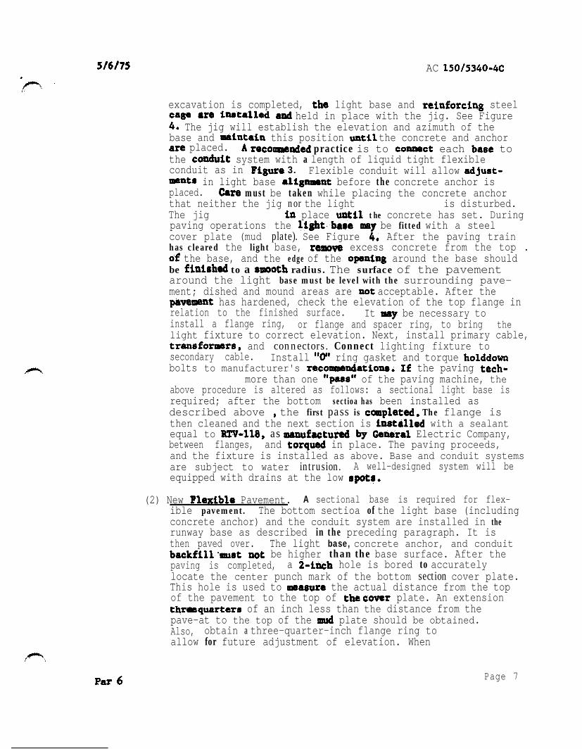
AC
excavation is completed light base and steel held in place with the jig See Figure
The jig will establish the elevation and azimuth of thebase and this position the concrete and anchor
placed practice is to each to the system with a length of liquid tight flexibleconduit as in 3 Flexible conduit will allow
in light base before the concrete anchor is placed must be taken while placing the concrete anchorthat neither the jig nor the light bese alignumnt is disturbed The jig Bust remaia place the concrete has set Duringpaving operations the be fitted with a steel cover plate (mud plate) See Figure After the paving trainhas cleared the light base excess concrete from the top
the base and the edge of the around the base should be to a radius The surface of the pavementaround the light base must be level with the surrounding paveshyment dished and mound areas are acceptable After the
has hardened check the elevation of the top flange inrelation to the finished surface It be necessary toinstall a flange ring or flange and spacer ring to bring the light fixture to correct elevation Next install primary cable
and connectors Connect lighting fixture tosecondary cable Install ring gasket and torquebolts to manufacturers the pavingique utiliees more than one of the paving machine the above procedure is altered as follows a sectional light base isrequired after the bottom sectioa has been installed as described above the first pass is The flange isthen cleaned and the next section is with a sealant equal to as Electric Companybetween flanges and in place The paving proceedsand the fixture is installed as above Base and conduit systemsare subject to water intrusion A well-designed system will beequipped with drains at the low
(2) New Pavement A sectional base is required for flexshyible pavement The bottom sectioa of the light base (includingconcrete anchor) and the conduit system are installed in the runway base as described in the preceding paragraph It isthen paved over The light base concrete anchor and conduit
be higher than the base surface After the paving is completed a hole is bored to accuratelylocate the center punch mark of the bottom section cover plateThis hole is used to the actual distance from the topof the pavement to the top of plate An extension
of an inch less than the distance from the pave-at to the top of the plate should be obtained Also obtain a three-quarter-inch flange ring toallow for future adjustment of elevation When
Page 7
AC
- the extension is received a hole one-half inch larger than the diameter of the light should be drilled and the extensionflange ring and light fixture installed as described above The space between the walls of the hole up to the top ofthe adapter ring should be filled with liquid P-606 sealantSee Figure 6
Flexible Overlay The installation of a light base and conduitsystem in a pavement to be overlaid similar to that of a new flexible pavement except the bottom section of the lightbase and the conduit are set in openings made in the existing pavement The anchor and encasement of the conduit will be similar to that described in (2) New Flexible Pavement The use of a short length of liquid tight flexible conduit necessary to allow proper alignment The of the installation as described in the preceding paragraph
Overlay The installation of a lighting base and conduitsystem require8 acomblnation of techniques outlined inpreceding sections of (1) New Rigid Pavement and (3) FlexibleOverlay The base and conduit are installed as in (3) concrete is placed as in (1)
C Inset Installation
(1) Rigid Pavements Drill holes or recesses in the pavements to the light fixtures Saw to accommodate electrical circuits See typical installation details in Figure8 7 8 and
(a) Pavement Drilling and Sawing Provide appraPrimately l4shyinch clearance for sealer material between the bottom and side of the lneet base receptacle and the recessProvide extra depth where sawed wlreways cross pavement joints See Figure 7 for detail
ght Fixtures Install centerline lights to follow the longitudinal contour Place touchdown zone lights level a horizontal plane Unless otherwise epeclfied the tolerance for being level is
Figure 2
Rlor torsquoplacing the inset base receptacle in the drilledhole clean all external surfaces to assure an adequatebond between fixture sealer and pavement Sand blast if necessary Avoid handling the fixtures by the leads
15053404c CHC 1
Orientate the fixture rrmgethe leedrrsquoproperly with to their in the
temporary if required for blocking the entrance the drilled hole The will retain the realer during of the bare receptacleThe for the bare a line parallel with the rummy centerline
are 88ura proper azimuth levetioa and level
Cover the bottom of the receptacle with 6 paateshytype dhe8Fve material Place a quantity of
in tha hole Place the bare in the drilled hole to force the of the at least
inch be taken to work out entrapped air a liquid (paragraph fill the between
the bare of the hole Liquid rearer 8hould be ppliedonly between the-iaret b88e regeptacle and the
of the hole not be applied the Of the hole and the top 888emb1y
to the of the wires in the pavement chamfer or to -inch radiur vertical
of the at and See Figure 10 clean to properbond between pavement material and the If
have been there with a velocity of after sawing to of the
bedryandclean
(d) Wirer place the lo THWN in th wirewaye from ormarr near the runway edge to the light fixture
an number (3 feet on of or device8 to hold the wires in place at least one-half of an inch below the payment 6urshy
wedge8 are not acceptablethe top of the wedge8 below the pavement Splicethe light fixture lead8 to the lO THWN wirer Use pre-
Make the crimped with a tool that require6 a complete crimp before
the Of the Permit no the conductor except at each light If
the in tape or real the of wire8 to prevent the of moisture Seal in the with P-606 Apply in with AC aad the followins
Page 9Par
_
AC --
Pour sealer in until surface of wire covered
If by the manufacturer pour clean eand into the liquid until a alight smountof sand on the Use clean sand that through a Number40
Fill the remainder of the to pavement level withliquid sealer but in case above pavement level
Sealer material extending above pavement surface be removed
Pavement Install light fixtures and wires flexshyible ilar to the procedures in rigid
with the following precautions
lean the holes and before 80 the dry aggregate of the pavement Fe
exposed
(for on fixtures) so that15 minutes
sealant conform8 to P-606 or Specification E-2373 to real wires in
be installed on runways where See 10 When additional
the inset light removed and the bare is fitted with cover paving then applied lightbase and junction box When the paving is completed
the junction box and light bare by coring RemoveAdd to the junction box and light
bare cover box and on bare
d Vault
(2) Exercise campe while working the vault to preventiron stripping or other foreign
collecting on switches and otherCollect and remove all residue as the
Use cover8 or shields during installashytion wiring protect component8 from foreign matter
in accordance with
10 Par 6
Cable Cable shall be in accordance with L-108Advisory Circular In the event of a conflict between
paragraph L-108 this shell govern Providesufficient slack to enable primary cable connections to beabove ground be splices the cable
light Connections of cable to shall be made with L-823 cable the
primary are taped secondary connections not rubber tape by plastic where connector and cable joinedUse only tape where the two halves cable ends if connections not made
7
8 Conduit Inspection and testing of lightingduring ionare important Certain components
be for corrective action after the final installation
Inspect the installed light to if the has been installed in accordance with the instructions and at the proper elevation
Check the alignment of all units to determine if lightingfixtures have been installed in accordance with design and
Check the fixtures and bases to determine if the securinghardware has been tightened in accordance with the
instructions
inspect the lighting fixture8 to determine if the lenser 8nd channels in front of the are clean
Tart vault equipment and circuit8 in AC L-109 and L-108 respectively
Measure and record all operating voltage8 and currents and insulation resistance
b Inset In addition to the above perform the inspection and for these lights concurrently with the because
of -inaccessibility of soxs coxponents ampfore fillingwireways identify and test the secondary series circuit for each
of runway for continuity and insulation to ground Check the insulation 8 (minimum)insul8tion resirtmce tester An acceptable circuit ha8 aof least so After fixtures and wirer are perform a inspection of the sealer in the and around the fixture8 to determine if 811 voids are filled and that is at the proper level with respect to the surface After these
Par 6rsquo Page 11
AC
tests have been performed and the lighting circuits are completedtest the system by continuous operation for a period of not lessthan one-half hour prior to acceptance The tests include the operation of each control not less than 10 times
a
a General Establish a maintenance program at airports where centershyline and touchdown zone lights are installed to insure properoperation and dependable service from the equipment The effectiveshyness of a will soon depreciate unless it is properlytained Maintenance recommendations are contained in AdvisoryCircular Maintenance Guide for Determiningand Cleaning of Centerline and Touchdown Zone Lights
(1) Perform a daily operational check of all lighting fixturesthe runway centerline and touchdown zone lights and
visually inspect the light output If any lamps are out orfixtures are obscured record the location of the fixtures and replace the lamps or top fittings containing the opticallenses Replace lamps when the circuit is deactivated
(2) Clean the lighting fixtures regularly so that the system canmeet performance requirements for low visibility conditionsClean the lens and channel in front of the lens periodically
in accordance with manufacturers recommendations The regularity and type of cleaning will be dictated by the weatherconditions and the location of the fixtures
(3) Snow should be removed from around the lights with powerbroom if practical If it becomes necessary for snowplows to cross lights it is recommended that the blade be lifted
as a last resort should the blade be allowed to come in contact with the light Rubber and plastic-edge snowplowblades are that are especially suited for plowing wet or slushy snow snow removal techniques arecontained in AC
b
(1) Replacement Group replacement may be beneficial and should belsquoconsidered It is that lamps be replaced when the number hours of operation on top brightness stepequals the lamps rated ltfe
(2) Deenergite the circuit supplying the fixturecontaining the burned-out lamp Remove the top assembly A
practice is to replace the complete top assembly and subsequently it in a clean indoor location Replace the seals if they appear to be worn or damaged Beforethe top assembly is replaced clean and dry the unit Properly
Par 7Page 12
3
C
d
Par
AC
position seat all gaskets Tighten all screws bolts or other securing hardware in accordance with manufacturerrsquos
(If fixture8 are not properly secured theymight be damaged by normal aircraft
Removal of Water The lighting fixtures are designed to excludeboth ground and surface water from entering water someshytimes enters and becomes a serious problem particularly wherefreezing temperatures are encountered If the barer or receptaclesfill withlsquowater freezing cause damage to the fixture byshearing the top assembly hardware or rupturing the base or receptacle To prevent this establish a regular schedule forremoving water especially during the fall and winter monthsEstablish a regular schedule for tightening cover bolts If any of the fixtures contain water remove this water and clean and dry the receptacle lamp and electrical contacts Properlyposition andor seat all and tighten the hardware securingthe top assembly in accordance with the instructions
Cable Check home runs of cables with a (minimum) insulashytion resistance tester before the installation been accepted
records of the resistance values obtained In order to check the condition of the system compare periodic reading6 with theinitial values In an acceptable system the initial insulationresistance value is not less than 50 and much higher (in the order of hundreds of megohms) If the periodicchecks reveal progressive deterioration or faults take steps promptly
(1) Make periodic insulation checks by first the regulator Monthly checks are Open the series disconnects Connect one lead of the insulation
to the load side of one disconnect connect the other lead to a proven ground Operate the test equipment inaccordance with instrument
(2) Maintenance personnel must be that high open-circuitvoltage is present when the secondary of an constant current regulator opened Troublerhooting is complicated by the fact that in instances the interconnecting wiresare sealed in the runway pavement8 and the fixtures are located in an active part of the runway For this reason itis important to check the system during the installation and to establish an effective preventive maintenance program
Page 13
AC
Spare Parts The importance of stocking spare parts cannot be overemphasized Spare example should be procured whenthe lighting system into Operation and when the begin indicates that frantic requests for
delivery of replacement lamps often cannot be met by thesupplier Replaceable parts of fixtures and replaceable componentsof regulators should also be stocked for maintenance purposes
Vault Keep the vault (AC Item L-109) uncluttered toprevent dirt from accumulating in control compartmenta and to allowequipment to be accessible at Mount legible warning
in conapicious places Make periodic checks of supply voltage and output current
Test To the light Of inpavement lightingobtain the equipment described in AC Maintenance Guide for Determining Degradation and Cleaning of Centerline and Touchshydown Zone Lights In addition the following equipment is recomshymended
(minimum) insulation resistance testerVolt-ohm meter and clamp-on ammeterRubber safetyHot stick
Other test equipment as required by a particular
ParPage 14
AC 1
1 ( A C ) F e d e r a l
cl2malarr and thereto It axplains the
sale well free AC also
(1) AC and Statue cb Regulatlau3~
(2) AC for and Alz3iortr Dbltrlct
(3) AC 1505$b619 Taxlway
(4) AC Maintenance Guldt
AC for L-821 Alrpti Llghtlq Panel
(6) AC Electrical Cables
for ~cntstant current
(8) AC for L-841 far Pilot of
for andReceptacle
(10) AC FM 6857~1~-pe LQht
AC for
for Airport Llghtlng
(13) AC Removal ar8
1 AC 1 Appendix 1
b latest Issuance of AC Standards for SpecifyingAirports can be In AC be
obtained from the Superintendent of Documents US Office Washiagton DC
copies of Eleckrlficatian AdministratIon Bulletin for Telephmo Cables and
Bulletin for CablesUS
Washington
Cbtaln copies of (ASG)Power Series Airport Liamphtinamp General
Office EavalSupply Depot 5901 Avenue Philadelphia Pennsylvania Attention Code
4 copies of FAA-E-2373 Adhesive for Sealing Wire in Pavements
Configuration Branch IndependenceAvenue SW Waehingtoa DC 20591
5 IFCEA Publlcatlons S-66-524 of
Electrical Energy and Ribber-insulated and Cable for the and af ElectrIcal Energy be obtained
the Electrical 155
Par 1
-
-
touchdown per
0 centerline
bbI whit
r o w - white red
Conterlinr light8 2rsquo to the or left of runwoy lo avoid the centerline paint
2 Thr crntorlinr l i g h t s m a y 0 o f o o f
3 The 3000 foot 1000 foot of runwoy on alternate and light rignol
4 foot of runwoy on rod signal
touchdown light bon not required to locotrd at thr 2 f o r
1 RUNWAY LIGHTING LAYOUT
S9 NVHL I O N 0 1
3 8
V N I
- - - - -
o f
-
~
BASE VARIES
AR
BASE AND OR SUBBASE
ANCHOR
3 SECTION THROUGH BASE AND ANCHOR BASE AND
AC 1 Appendix 2
JIG FOR ALIGNING BASE I
PC CONCRETE ANCHOR
AOJUSTABLE BAR CAGE
SUBBASE
NOTE
COVER PLATE SHOWN FOR ILLUSTRATION ONLY USE OF MUD PLATES CONSTRUCTION RINGS EXTENSIONS ON PAVING
Page 4
rsquo
1
PAVEMENTshy
PLATE SHOWN FOR ONLY USE MUD PLATES RINGS ON
I
L-550 FIXTURE
L-057 BASE
ASPHALT
BASE AND OR L- 555ASE
VARIES
f
VARIES
)
pnee
FIGURE
I2W Itmiddot
bullc-c middot---middot
NL bull
r n-
)
=n
011 bull fll --
- lfiiCifle1 bull ~ __ ltllt_ _ - - -_
bull _ OttbullY __ _ Wtrbull
INSTAIIATIW pErAILS FOil ToucHDOWN ZONE AND CENTERLINE LlGJflS
7 TYPICALWIREWAY
--
-
-
and
JOINT
DE TAIL
NOTES
w i r e s l e s s t h a n below sea t compound s e e S e c t i o n s A A and f o r d i m e n s i o n s
2 d i m e n s i o n s o f cored hole f o r - 8 5 0 f i x t u r e D e p t h
8 TYPICAL INSTALLATUJN DETAILS INSET LIGHTING FIXTURES
-
Appendix 2
HOUSING INSTALLATION
C U L L
SECTION 0
ARE INSTALLED IN WITH L-106
STANDARDS FOR OF
CONNECTORS-NUMBERS REFER TO L
NUMBERS
TYPICAL XTKES - - -
0 Awe
TRANSFORMER CONNECTIONS
01 3lUl3Id
and fobficote bon IO t h e f o o d i n speciftcaiti L- 850
Fill junction bon with o j u n c t i o n b o x l e v e l w i t h t h ei s t o prevenl waler f r o m h fhe junction b o r
t h e bar and t o oermit ins~ollotion amp v i c eProvide o ond grommets lo
b o a
FIGURE 11 JUNCTION BOX FOR INSET FIXTURE INSTALLATIONS
rsquo
lsquo
l
REGULATOR LOCATED
IN VAULT LIGHTS
W A T l S L - 6 5 0 T Y P E A
L - 8 2 8
SERIES LOOP
CENTERLINE ZONE]
CONSTANT CURRENT
REGULATOR LOCATED IN VAULT I TRANSFORMER L-830
200 WATTS IN L -657 BASE
F IXTURE L-
2 0 0 W T Y P E
TOUCHOOWN ZONE1
LIGHTING FIXTURE 200
12 ONE LINE DIAGRAM SERIES LIGHTING
AC Appendix 2
I
L SrsquoLI-rsquo CONTROL PANEL IN TOWER
L -828
CONTROL 7 C U R R E N T WIRES SEE NOTE S T E P - T Y P E
REGULATOR WITH INTERNAL
PRIMARY OIL
ISW I
I rdquo
I
I
OUTPUT
F U S E D C U T O U T
I
LIGHTNING ARRESTOR
CUTOUT W I T H
REGULATOR)TO RUNWAYNOTE LIGHTING CIRCUIT
C I R C U I T U P A P P R O X 3 0 0 0 O R
D R O P I S N O T D R O P I S I N O R A T CORTROI TERYIRALLOU C O N T R O L S E U S E D
13 WIampG REGULATOR WITH CONTROL AND SWITCH
13
AC
NOTES
AS A ELECTRICAL INSTALLATION CONFORM TO APPLICABLE SECTIONS OF THE NATIONAL ELECTRICAL CODE
PANEL TOWER
REMOTE OIL SWITCH
H2 INPUT
L - 8 2 8 CONSTANT CURRENT STEP TYPE
WITH EXTERNAL PRIMARY OIL
SWITCH
O U T P U T
ARRESTOR SEE NOTE 4
LIGHTNING ARRESTOR SEE NOTE4
7 WIRES SEE NOTE
AND CODES
2 MAY SE USED SEE NOTE I FIGURE
WHEN COUNTERPOISE IS IT INSTALLED IN ACCORDANCE WITH ITEM OF STANDARDS FOR SPECIFYING CONSTRUCTION OF AIRPORTS
4 ARRESTORS FURNISHED REGULATOR
FUSED CUTOUT-
14 TYPICAL REGULATOR WITH CONTROL POWER MD PRIMARY OIL SWITCH
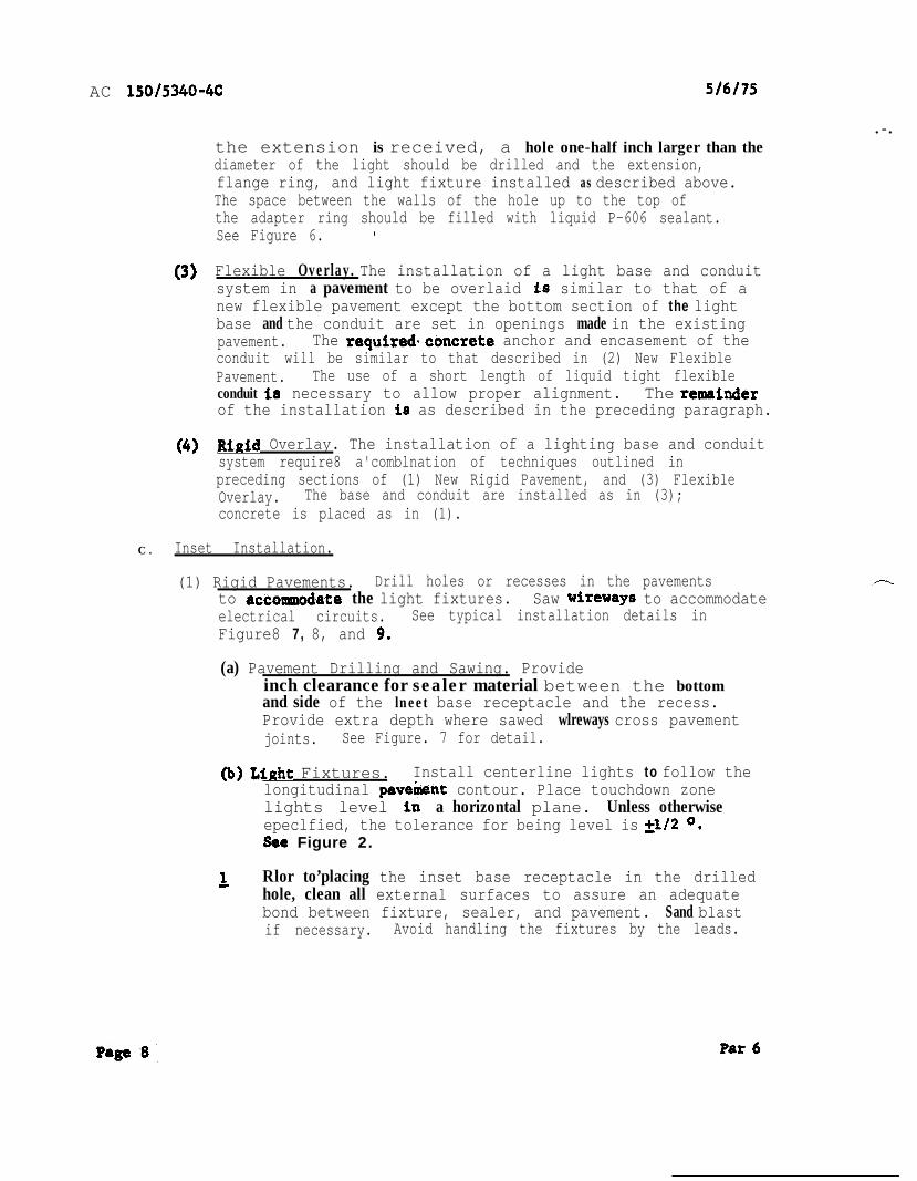
AC
- the extension is received a hole one-half inch larger than the diameter of the light should be drilled and the extensionflange ring and light fixture installed as described above The space between the walls of the hole up to the top ofthe adapter ring should be filled with liquid P-606 sealantSee Figure 6
Flexible Overlay The installation of a light base and conduitsystem in a pavement to be overlaid similar to that of a new flexible pavement except the bottom section of the lightbase and the conduit are set in openings made in the existing pavement The anchor and encasement of the conduit will be similar to that described in (2) New Flexible Pavement The use of a short length of liquid tight flexible conduit necessary to allow proper alignment The of the installation as described in the preceding paragraph
Overlay The installation of a lighting base and conduitsystem require8 acomblnation of techniques outlined inpreceding sections of (1) New Rigid Pavement and (3) FlexibleOverlay The base and conduit are installed as in (3) concrete is placed as in (1)
C Inset Installation
(1) Rigid Pavements Drill holes or recesses in the pavements to the light fixtures Saw to accommodate electrical circuits See typical installation details in Figure8 7 8 and
(a) Pavement Drilling and Sawing Provide appraPrimately l4shyinch clearance for sealer material between the bottom and side of the lneet base receptacle and the recessProvide extra depth where sawed wlreways cross pavement joints See Figure 7 for detail
ght Fixtures Install centerline lights to follow the longitudinal contour Place touchdown zone lights level a horizontal plane Unless otherwise epeclfied the tolerance for being level is
Figure 2
Rlor torsquoplacing the inset base receptacle in the drilledhole clean all external surfaces to assure an adequatebond between fixture sealer and pavement Sand blast if necessary Avoid handling the fixtures by the leads
15053404c CHC 1
Orientate the fixture rrmgethe leedrrsquoproperly with to their in the
temporary if required for blocking the entrance the drilled hole The will retain the realer during of the bare receptacleThe for the bare a line parallel with the rummy centerline
are 88ura proper azimuth levetioa and level
Cover the bottom of the receptacle with 6 paateshytype dhe8Fve material Place a quantity of
in tha hole Place the bare in the drilled hole to force the of the at least
inch be taken to work out entrapped air a liquid (paragraph fill the between
the bare of the hole Liquid rearer 8hould be ppliedonly between the-iaret b88e regeptacle and the
of the hole not be applied the Of the hole and the top 888emb1y
to the of the wires in the pavement chamfer or to -inch radiur vertical
of the at and See Figure 10 clean to properbond between pavement material and the If
have been there with a velocity of after sawing to of the
bedryandclean
(d) Wirer place the lo THWN in th wirewaye from ormarr near the runway edge to the light fixture
an number (3 feet on of or device8 to hold the wires in place at least one-half of an inch below the payment 6urshy
wedge8 are not acceptablethe top of the wedge8 below the pavement Splicethe light fixture lead8 to the lO THWN wirer Use pre-
Make the crimped with a tool that require6 a complete crimp before
the Of the Permit no the conductor except at each light If
the in tape or real the of wire8 to prevent the of moisture Seal in the with P-606 Apply in with AC aad the followins
Page 9Par
_
AC --
Pour sealer in until surface of wire covered
If by the manufacturer pour clean eand into the liquid until a alight smountof sand on the Use clean sand that through a Number40
Fill the remainder of the to pavement level withliquid sealer but in case above pavement level
Sealer material extending above pavement surface be removed
Pavement Install light fixtures and wires flexshyible ilar to the procedures in rigid
with the following precautions
lean the holes and before 80 the dry aggregate of the pavement Fe
exposed
(for on fixtures) so that15 minutes
sealant conform8 to P-606 or Specification E-2373 to real wires in
be installed on runways where See 10 When additional
the inset light removed and the bare is fitted with cover paving then applied lightbase and junction box When the paving is completed
the junction box and light bare by coring RemoveAdd to the junction box and light
bare cover box and on bare
d Vault
(2) Exercise campe while working the vault to preventiron stripping or other foreign
collecting on switches and otherCollect and remove all residue as the
Use cover8 or shields during installashytion wiring protect component8 from foreign matter
in accordance with
10 Par 6
Cable Cable shall be in accordance with L-108Advisory Circular In the event of a conflict between
paragraph L-108 this shell govern Providesufficient slack to enable primary cable connections to beabove ground be splices the cable
light Connections of cable to shall be made with L-823 cable the
primary are taped secondary connections not rubber tape by plastic where connector and cable joinedUse only tape where the two halves cable ends if connections not made
7
8 Conduit Inspection and testing of lightingduring ionare important Certain components
be for corrective action after the final installation
Inspect the installed light to if the has been installed in accordance with the instructions and at the proper elevation
Check the alignment of all units to determine if lightingfixtures have been installed in accordance with design and
Check the fixtures and bases to determine if the securinghardware has been tightened in accordance with the
instructions
inspect the lighting fixture8 to determine if the lenser 8nd channels in front of the are clean
Tart vault equipment and circuit8 in AC L-109 and L-108 respectively
Measure and record all operating voltage8 and currents and insulation resistance
b Inset In addition to the above perform the inspection and for these lights concurrently with the because
of -inaccessibility of soxs coxponents ampfore fillingwireways identify and test the secondary series circuit for each
of runway for continuity and insulation to ground Check the insulation 8 (minimum)insul8tion resirtmce tester An acceptable circuit ha8 aof least so After fixtures and wirer are perform a inspection of the sealer in the and around the fixture8 to determine if 811 voids are filled and that is at the proper level with respect to the surface After these
Par 6rsquo Page 11
AC
tests have been performed and the lighting circuits are completedtest the system by continuous operation for a period of not lessthan one-half hour prior to acceptance The tests include the operation of each control not less than 10 times
a
a General Establish a maintenance program at airports where centershyline and touchdown zone lights are installed to insure properoperation and dependable service from the equipment The effectiveshyness of a will soon depreciate unless it is properlytained Maintenance recommendations are contained in AdvisoryCircular Maintenance Guide for Determiningand Cleaning of Centerline and Touchdown Zone Lights
(1) Perform a daily operational check of all lighting fixturesthe runway centerline and touchdown zone lights and
visually inspect the light output If any lamps are out orfixtures are obscured record the location of the fixtures and replace the lamps or top fittings containing the opticallenses Replace lamps when the circuit is deactivated
(2) Clean the lighting fixtures regularly so that the system canmeet performance requirements for low visibility conditionsClean the lens and channel in front of the lens periodically
in accordance with manufacturers recommendations The regularity and type of cleaning will be dictated by the weatherconditions and the location of the fixtures
(3) Snow should be removed from around the lights with powerbroom if practical If it becomes necessary for snowplows to cross lights it is recommended that the blade be lifted
as a last resort should the blade be allowed to come in contact with the light Rubber and plastic-edge snowplowblades are that are especially suited for plowing wet or slushy snow snow removal techniques arecontained in AC
b
(1) Replacement Group replacement may be beneficial and should belsquoconsidered It is that lamps be replaced when the number hours of operation on top brightness stepequals the lamps rated ltfe
(2) Deenergite the circuit supplying the fixturecontaining the burned-out lamp Remove the top assembly A
practice is to replace the complete top assembly and subsequently it in a clean indoor location Replace the seals if they appear to be worn or damaged Beforethe top assembly is replaced clean and dry the unit Properly
Par 7Page 12
3
C
d
Par
AC
position seat all gaskets Tighten all screws bolts or other securing hardware in accordance with manufacturerrsquos
(If fixture8 are not properly secured theymight be damaged by normal aircraft
Removal of Water The lighting fixtures are designed to excludeboth ground and surface water from entering water someshytimes enters and becomes a serious problem particularly wherefreezing temperatures are encountered If the barer or receptaclesfill withlsquowater freezing cause damage to the fixture byshearing the top assembly hardware or rupturing the base or receptacle To prevent this establish a regular schedule forremoving water especially during the fall and winter monthsEstablish a regular schedule for tightening cover bolts If any of the fixtures contain water remove this water and clean and dry the receptacle lamp and electrical contacts Properlyposition andor seat all and tighten the hardware securingthe top assembly in accordance with the instructions
Cable Check home runs of cables with a (minimum) insulashytion resistance tester before the installation been accepted
records of the resistance values obtained In order to check the condition of the system compare periodic reading6 with theinitial values In an acceptable system the initial insulationresistance value is not less than 50 and much higher (in the order of hundreds of megohms) If the periodicchecks reveal progressive deterioration or faults take steps promptly
(1) Make periodic insulation checks by first the regulator Monthly checks are Open the series disconnects Connect one lead of the insulation
to the load side of one disconnect connect the other lead to a proven ground Operate the test equipment inaccordance with instrument
(2) Maintenance personnel must be that high open-circuitvoltage is present when the secondary of an constant current regulator opened Troublerhooting is complicated by the fact that in instances the interconnecting wiresare sealed in the runway pavement8 and the fixtures are located in an active part of the runway For this reason itis important to check the system during the installation and to establish an effective preventive maintenance program
Page 13
AC
Spare Parts The importance of stocking spare parts cannot be overemphasized Spare example should be procured whenthe lighting system into Operation and when the begin indicates that frantic requests for
delivery of replacement lamps often cannot be met by thesupplier Replaceable parts of fixtures and replaceable componentsof regulators should also be stocked for maintenance purposes
Vault Keep the vault (AC Item L-109) uncluttered toprevent dirt from accumulating in control compartmenta and to allowequipment to be accessible at Mount legible warning
in conapicious places Make periodic checks of supply voltage and output current
Test To the light Of inpavement lightingobtain the equipment described in AC Maintenance Guide for Determining Degradation and Cleaning of Centerline and Touchshydown Zone Lights In addition the following equipment is recomshymended
(minimum) insulation resistance testerVolt-ohm meter and clamp-on ammeterRubber safetyHot stick
Other test equipment as required by a particular
ParPage 14
AC 1
1 ( A C ) F e d e r a l
cl2malarr and thereto It axplains the
sale well free AC also
(1) AC and Statue cb Regulatlau3~
(2) AC for and Alz3iortr Dbltrlct
(3) AC 1505$b619 Taxlway
(4) AC Maintenance Guldt
AC for L-821 Alrpti Llghtlq Panel
(6) AC Electrical Cables
for ~cntstant current
(8) AC for L-841 far Pilot of
for andReceptacle
(10) AC FM 6857~1~-pe LQht
AC for
for Airport Llghtlng
(13) AC Removal ar8
1 AC 1 Appendix 1
b latest Issuance of AC Standards for SpecifyingAirports can be In AC be
obtained from the Superintendent of Documents US Office Washiagton DC
copies of Eleckrlficatian AdministratIon Bulletin for Telephmo Cables and
Bulletin for CablesUS
Washington
Cbtaln copies of (ASG)Power Series Airport Liamphtinamp General
Office EavalSupply Depot 5901 Avenue Philadelphia Pennsylvania Attention Code
4 copies of FAA-E-2373 Adhesive for Sealing Wire in Pavements
Configuration Branch IndependenceAvenue SW Waehingtoa DC 20591
5 IFCEA Publlcatlons S-66-524 of
Electrical Energy and Ribber-insulated and Cable for the and af ElectrIcal Energy be obtained
the Electrical 155
Par 1
-
-
touchdown per
0 centerline
bbI whit
r o w - white red
Conterlinr light8 2rsquo to the or left of runwoy lo avoid the centerline paint
2 Thr crntorlinr l i g h t s m a y 0 o f o o f
3 The 3000 foot 1000 foot of runwoy on alternate and light rignol
4 foot of runwoy on rod signal
touchdown light bon not required to locotrd at thr 2 f o r
1 RUNWAY LIGHTING LAYOUT
S9 NVHL I O N 0 1
3 8
V N I
- - - - -
o f
-
~
BASE VARIES
AR
BASE AND OR SUBBASE
ANCHOR
3 SECTION THROUGH BASE AND ANCHOR BASE AND
AC 1 Appendix 2
JIG FOR ALIGNING BASE I
PC CONCRETE ANCHOR
AOJUSTABLE BAR CAGE
SUBBASE
NOTE
COVER PLATE SHOWN FOR ILLUSTRATION ONLY USE OF MUD PLATES CONSTRUCTION RINGS EXTENSIONS ON PAVING
Page 4
rsquo
1
PAVEMENTshy
PLATE SHOWN FOR ONLY USE MUD PLATES RINGS ON
I
L-550 FIXTURE
L-057 BASE
ASPHALT
BASE AND OR L- 555ASE
VARIES
f
VARIES
)
pnee
FIGURE
I2W Itmiddot
bullc-c middot---middot
NL bull
r n-
)
=n
011 bull fll --
- lfiiCifle1 bull ~ __ ltllt_ _ - - -_
bull _ OttbullY __ _ Wtrbull
INSTAIIATIW pErAILS FOil ToucHDOWN ZONE AND CENTERLINE LlGJflS
7 TYPICALWIREWAY
--
-
-
and
JOINT
DE TAIL
NOTES
w i r e s l e s s t h a n below sea t compound s e e S e c t i o n s A A and f o r d i m e n s i o n s
2 d i m e n s i o n s o f cored hole f o r - 8 5 0 f i x t u r e D e p t h
8 TYPICAL INSTALLATUJN DETAILS INSET LIGHTING FIXTURES
-
Appendix 2
HOUSING INSTALLATION
C U L L
SECTION 0
ARE INSTALLED IN WITH L-106
STANDARDS FOR OF
CONNECTORS-NUMBERS REFER TO L
NUMBERS
TYPICAL XTKES - - -
0 Awe
TRANSFORMER CONNECTIONS
01 3lUl3Id
and fobficote bon IO t h e f o o d i n speciftcaiti L- 850
Fill junction bon with o j u n c t i o n b o x l e v e l w i t h t h ei s t o prevenl waler f r o m h fhe junction b o r
t h e bar and t o oermit ins~ollotion amp v i c eProvide o ond grommets lo
b o a
FIGURE 11 JUNCTION BOX FOR INSET FIXTURE INSTALLATIONS
rsquo
lsquo
l
REGULATOR LOCATED
IN VAULT LIGHTS
W A T l S L - 6 5 0 T Y P E A
L - 8 2 8
SERIES LOOP
CENTERLINE ZONE]
CONSTANT CURRENT
REGULATOR LOCATED IN VAULT I TRANSFORMER L-830
200 WATTS IN L -657 BASE
F IXTURE L-
2 0 0 W T Y P E
TOUCHOOWN ZONE1
LIGHTING FIXTURE 200
12 ONE LINE DIAGRAM SERIES LIGHTING
AC Appendix 2
I
L SrsquoLI-rsquo CONTROL PANEL IN TOWER
L -828
CONTROL 7 C U R R E N T WIRES SEE NOTE S T E P - T Y P E
REGULATOR WITH INTERNAL
PRIMARY OIL
ISW I
I rdquo
I
I
OUTPUT
F U S E D C U T O U T
I
LIGHTNING ARRESTOR
CUTOUT W I T H
REGULATOR)TO RUNWAYNOTE LIGHTING CIRCUIT
C I R C U I T U P A P P R O X 3 0 0 0 O R
D R O P I S N O T D R O P I S I N O R A T CORTROI TERYIRALLOU C O N T R O L S E U S E D
13 WIampG REGULATOR WITH CONTROL AND SWITCH
13
AC
NOTES
AS A ELECTRICAL INSTALLATION CONFORM TO APPLICABLE SECTIONS OF THE NATIONAL ELECTRICAL CODE
PANEL TOWER
REMOTE OIL SWITCH
H2 INPUT
L - 8 2 8 CONSTANT CURRENT STEP TYPE
WITH EXTERNAL PRIMARY OIL
SWITCH
O U T P U T
ARRESTOR SEE NOTE 4
LIGHTNING ARRESTOR SEE NOTE4
7 WIRES SEE NOTE
AND CODES
2 MAY SE USED SEE NOTE I FIGURE
WHEN COUNTERPOISE IS IT INSTALLED IN ACCORDANCE WITH ITEM OF STANDARDS FOR SPECIFYING CONSTRUCTION OF AIRPORTS
4 ARRESTORS FURNISHED REGULATOR
FUSED CUTOUT-
14 TYPICAL REGULATOR WITH CONTROL POWER MD PRIMARY OIL SWITCH
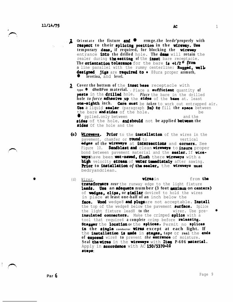
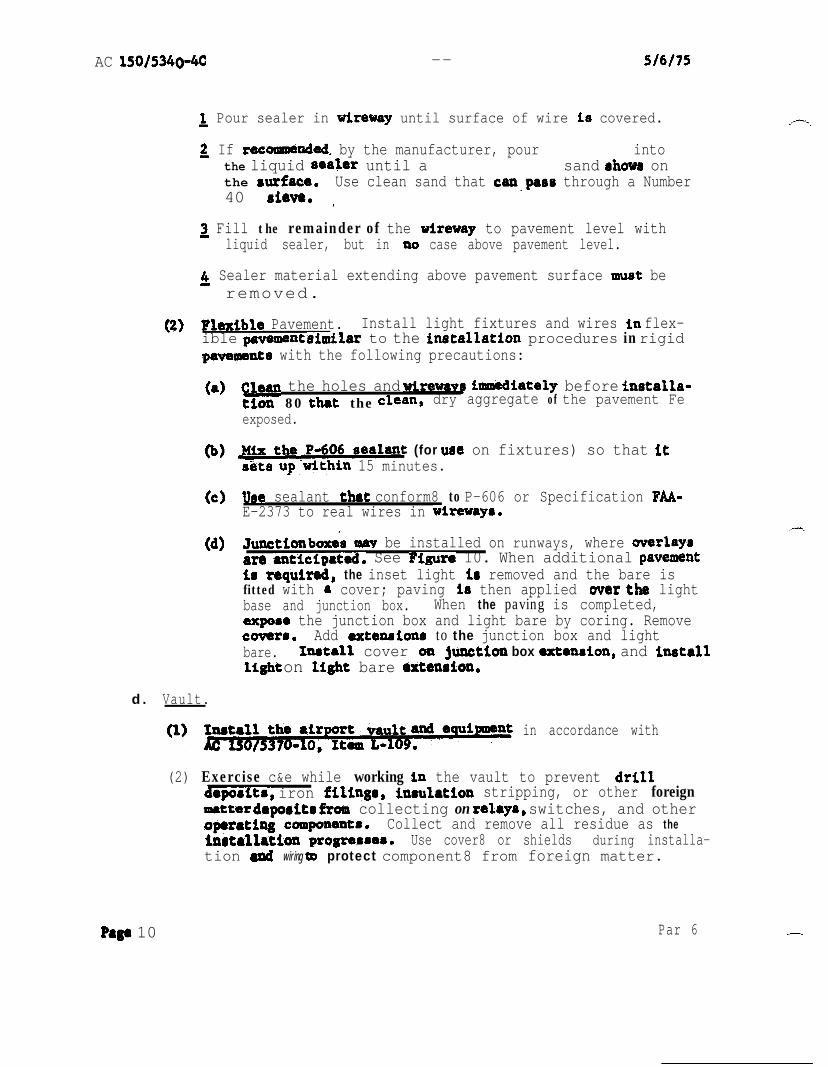
AC
tests have been performed and the lighting circuits are completedtest the system by continuous operation for a period of not lessthan one-half hour prior to acceptance The tests include the operation of each control not less than 10 times
a
a General Establish a maintenance program at airports where centershyline and touchdown zone lights are installed to insure properoperation and dependable service from the equipment The effectiveshyness of a will soon depreciate unless it is properlytained Maintenance recommendations are contained in AdvisoryCircular Maintenance Guide for Determiningand Cleaning of Centerline and Touchdown Zone Lights
(1) Perform a daily operational check of all lighting fixturesthe runway centerline and touchdown zone lights and
visually inspect the light output If any lamps are out orfixtures are obscured record the location of the fixtures and replace the lamps or top fittings containing the opticallenses Replace lamps when the circuit is deactivated
(2) Clean the lighting fixtures regularly so that the system canmeet performance requirements for low visibility conditionsClean the lens and channel in front of the lens periodically
in accordance with manufacturers recommendations The regularity and type of cleaning will be dictated by the weatherconditions and the location of the fixtures
(3) Snow should be removed from around the lights with powerbroom if practical If it becomes necessary for snowplows to cross lights it is recommended that the blade be lifted
as a last resort should the blade be allowed to come in contact with the light Rubber and plastic-edge snowplowblades are that are especially suited for plowing wet or slushy snow snow removal techniques arecontained in AC
b
(1) Replacement Group replacement may be beneficial and should belsquoconsidered It is that lamps be replaced when the number hours of operation on top brightness stepequals the lamps rated ltfe
(2) Deenergite the circuit supplying the fixturecontaining the burned-out lamp Remove the top assembly A
practice is to replace the complete top assembly and subsequently it in a clean indoor location Replace the seals if they appear to be worn or damaged Beforethe top assembly is replaced clean and dry the unit Properly
Par 7Page 12
3
C
d
Par
AC
position seat all gaskets Tighten all screws bolts or other securing hardware in accordance with manufacturerrsquos
(If fixture8 are not properly secured theymight be damaged by normal aircraft
Removal of Water The lighting fixtures are designed to excludeboth ground and surface water from entering water someshytimes enters and becomes a serious problem particularly wherefreezing temperatures are encountered If the barer or receptaclesfill withlsquowater freezing cause damage to the fixture byshearing the top assembly hardware or rupturing the base or receptacle To prevent this establish a regular schedule forremoving water especially during the fall and winter monthsEstablish a regular schedule for tightening cover bolts If any of the fixtures contain water remove this water and clean and dry the receptacle lamp and electrical contacts Properlyposition andor seat all and tighten the hardware securingthe top assembly in accordance with the instructions
Cable Check home runs of cables with a (minimum) insulashytion resistance tester before the installation been accepted
records of the resistance values obtained In order to check the condition of the system compare periodic reading6 with theinitial values In an acceptable system the initial insulationresistance value is not less than 50 and much higher (in the order of hundreds of megohms) If the periodicchecks reveal progressive deterioration or faults take steps promptly
(1) Make periodic insulation checks by first the regulator Monthly checks are Open the series disconnects Connect one lead of the insulation
to the load side of one disconnect connect the other lead to a proven ground Operate the test equipment inaccordance with instrument
(2) Maintenance personnel must be that high open-circuitvoltage is present when the secondary of an constant current regulator opened Troublerhooting is complicated by the fact that in instances the interconnecting wiresare sealed in the runway pavement8 and the fixtures are located in an active part of the runway For this reason itis important to check the system during the installation and to establish an effective preventive maintenance program
Page 13
AC
Spare Parts The importance of stocking spare parts cannot be overemphasized Spare example should be procured whenthe lighting system into Operation and when the begin indicates that frantic requests for
delivery of replacement lamps often cannot be met by thesupplier Replaceable parts of fixtures and replaceable componentsof regulators should also be stocked for maintenance purposes
Vault Keep the vault (AC Item L-109) uncluttered toprevent dirt from accumulating in control compartmenta and to allowequipment to be accessible at Mount legible warning
in conapicious places Make periodic checks of supply voltage and output current
Test To the light Of inpavement lightingobtain the equipment described in AC Maintenance Guide for Determining Degradation and Cleaning of Centerline and Touchshydown Zone Lights In addition the following equipment is recomshymended
(minimum) insulation resistance testerVolt-ohm meter and clamp-on ammeterRubber safetyHot stick
Other test equipment as required by a particular
ParPage 14
AC 1
1 ( A C ) F e d e r a l
cl2malarr and thereto It axplains the
sale well free AC also
(1) AC and Statue cb Regulatlau3~
(2) AC for and Alz3iortr Dbltrlct
(3) AC 1505$b619 Taxlway
(4) AC Maintenance Guldt
AC for L-821 Alrpti Llghtlq Panel
(6) AC Electrical Cables
for ~cntstant current
(8) AC for L-841 far Pilot of
for andReceptacle
(10) AC FM 6857~1~-pe LQht
AC for
for Airport Llghtlng
(13) AC Removal ar8
1 AC 1 Appendix 1
b latest Issuance of AC Standards for SpecifyingAirports can be In AC be
obtained from the Superintendent of Documents US Office Washiagton DC
copies of Eleckrlficatian AdministratIon Bulletin for Telephmo Cables and
Bulletin for CablesUS
Washington
Cbtaln copies of (ASG)Power Series Airport Liamphtinamp General
Office EavalSupply Depot 5901 Avenue Philadelphia Pennsylvania Attention Code
4 copies of FAA-E-2373 Adhesive for Sealing Wire in Pavements
Configuration Branch IndependenceAvenue SW Waehingtoa DC 20591
5 IFCEA Publlcatlons S-66-524 of
Electrical Energy and Ribber-insulated and Cable for the and af ElectrIcal Energy be obtained
the Electrical 155
Par 1
-
-
touchdown per
0 centerline
bbI whit
r o w - white red
Conterlinr light8 2rsquo to the or left of runwoy lo avoid the centerline paint
2 Thr crntorlinr l i g h t s m a y 0 o f o o f
3 The 3000 foot 1000 foot of runwoy on alternate and light rignol
4 foot of runwoy on rod signal
touchdown light bon not required to locotrd at thr 2 f o r
1 RUNWAY LIGHTING LAYOUT
S9 NVHL I O N 0 1
3 8
V N I
- - - - -
o f
-
~
BASE VARIES
AR
BASE AND OR SUBBASE
ANCHOR
3 SECTION THROUGH BASE AND ANCHOR BASE AND
AC 1 Appendix 2
JIG FOR ALIGNING BASE I
PC CONCRETE ANCHOR
AOJUSTABLE BAR CAGE
SUBBASE
NOTE
COVER PLATE SHOWN FOR ILLUSTRATION ONLY USE OF MUD PLATES CONSTRUCTION RINGS EXTENSIONS ON PAVING
Page 4
rsquo
1
PAVEMENTshy
PLATE SHOWN FOR ONLY USE MUD PLATES RINGS ON
I
L-550 FIXTURE
L-057 BASE
ASPHALT
BASE AND OR L- 555ASE
VARIES
f
VARIES
)
pnee
FIGURE
I2W Itmiddot
bullc-c middot---middot
NL bull
r n-
)
=n
011 bull fll --
- lfiiCifle1 bull ~ __ ltllt_ _ - - -_
bull _ OttbullY __ _ Wtrbull
INSTAIIATIW pErAILS FOil ToucHDOWN ZONE AND CENTERLINE LlGJflS
7 TYPICALWIREWAY
--
-
-
and
JOINT
DE TAIL
NOTES
w i r e s l e s s t h a n below sea t compound s e e S e c t i o n s A A and f o r d i m e n s i o n s
2 d i m e n s i o n s o f cored hole f o r - 8 5 0 f i x t u r e D e p t h
8 TYPICAL INSTALLATUJN DETAILS INSET LIGHTING FIXTURES
-
Appendix 2
HOUSING INSTALLATION
C U L L
SECTION 0
ARE INSTALLED IN WITH L-106
STANDARDS FOR OF
CONNECTORS-NUMBERS REFER TO L
NUMBERS
TYPICAL XTKES - - -
0 Awe
TRANSFORMER CONNECTIONS
01 3lUl3Id
and fobficote bon IO t h e f o o d i n speciftcaiti L- 850
Fill junction bon with o j u n c t i o n b o x l e v e l w i t h t h ei s t o prevenl waler f r o m h fhe junction b o r
t h e bar and t o oermit ins~ollotion amp v i c eProvide o ond grommets lo
b o a
FIGURE 11 JUNCTION BOX FOR INSET FIXTURE INSTALLATIONS
rsquo
lsquo
l
REGULATOR LOCATED
IN VAULT LIGHTS
W A T l S L - 6 5 0 T Y P E A
L - 8 2 8
SERIES LOOP
CENTERLINE ZONE]
CONSTANT CURRENT
REGULATOR LOCATED IN VAULT I TRANSFORMER L-830
200 WATTS IN L -657 BASE
F IXTURE L-
2 0 0 W T Y P E
TOUCHOOWN ZONE1
LIGHTING FIXTURE 200
12 ONE LINE DIAGRAM SERIES LIGHTING
AC Appendix 2
I
L SrsquoLI-rsquo CONTROL PANEL IN TOWER
L -828
CONTROL 7 C U R R E N T WIRES SEE NOTE S T E P - T Y P E
REGULATOR WITH INTERNAL
PRIMARY OIL
ISW I
I rdquo
I
I
OUTPUT
F U S E D C U T O U T
I
LIGHTNING ARRESTOR
CUTOUT W I T H
REGULATOR)TO RUNWAYNOTE LIGHTING CIRCUIT
C I R C U I T U P A P P R O X 3 0 0 0 O R
D R O P I S N O T D R O P I S I N O R A T CORTROI TERYIRALLOU C O N T R O L S E U S E D
13 WIampG REGULATOR WITH CONTROL AND SWITCH
13
AC
NOTES
AS A ELECTRICAL INSTALLATION CONFORM TO APPLICABLE SECTIONS OF THE NATIONAL ELECTRICAL CODE
PANEL TOWER
REMOTE OIL SWITCH
H2 INPUT
L - 8 2 8 CONSTANT CURRENT STEP TYPE
WITH EXTERNAL PRIMARY OIL
SWITCH
O U T P U T
ARRESTOR SEE NOTE 4
LIGHTNING ARRESTOR SEE NOTE4
7 WIRES SEE NOTE
AND CODES
2 MAY SE USED SEE NOTE I FIGURE
WHEN COUNTERPOISE IS IT INSTALLED IN ACCORDANCE WITH ITEM OF STANDARDS FOR SPECIFYING CONSTRUCTION OF AIRPORTS
4 ARRESTORS FURNISHED REGULATOR
FUSED CUTOUT-
14 TYPICAL REGULATOR WITH CONTROL POWER MD PRIMARY OIL SWITCH
AC
Spare Parts The importance of stocking spare parts cannot be overemphasized Spare example should be procured whenthe lighting system into Operation and when the begin indicates that frantic requests for
delivery of replacement lamps often cannot be met by thesupplier Replaceable parts of fixtures and replaceable componentsof regulators should also be stocked for maintenance purposes
Vault Keep the vault (AC Item L-109) uncluttered toprevent dirt from accumulating in control compartmenta and to allowequipment to be accessible at Mount legible warning
in conapicious places Make periodic checks of supply voltage and output current
Test To the light Of inpavement lightingobtain the equipment described in AC Maintenance Guide for Determining Degradation and Cleaning of Centerline and Touchshydown Zone Lights In addition the following equipment is recomshymended
(minimum) insulation resistance testerVolt-ohm meter and clamp-on ammeterRubber safetyHot stick
Other test equipment as required by a particular
ParPage 14
AC 1
1 ( A C ) F e d e r a l
cl2malarr and thereto It axplains the
sale well free AC also
(1) AC and Statue cb Regulatlau3~
(2) AC for and Alz3iortr Dbltrlct
(3) AC 1505$b619 Taxlway
(4) AC Maintenance Guldt
AC for L-821 Alrpti Llghtlq Panel
(6) AC Electrical Cables
for ~cntstant current
(8) AC for L-841 far Pilot of
for andReceptacle
(10) AC FM 6857~1~-pe LQht
AC for
for Airport Llghtlng
(13) AC Removal ar8
1 AC 1 Appendix 1
b latest Issuance of AC Standards for SpecifyingAirports can be In AC be
obtained from the Superintendent of Documents US Office Washiagton DC
copies of Eleckrlficatian AdministratIon Bulletin for Telephmo Cables and
Bulletin for CablesUS
Washington
Cbtaln copies of (ASG)Power Series Airport Liamphtinamp General
Office EavalSupply Depot 5901 Avenue Philadelphia Pennsylvania Attention Code
4 copies of FAA-E-2373 Adhesive for Sealing Wire in Pavements
Configuration Branch IndependenceAvenue SW Waehingtoa DC 20591
5 IFCEA Publlcatlons S-66-524 of
Electrical Energy and Ribber-insulated and Cable for the and af ElectrIcal Energy be obtained
the Electrical 155
Par 1
-
-
touchdown per
0 centerline
bbI whit
r o w - white red
Conterlinr light8 2rsquo to the or left of runwoy lo avoid the centerline paint
2 Thr crntorlinr l i g h t s m a y 0 o f o o f
3 The 3000 foot 1000 foot of runwoy on alternate and light rignol
4 foot of runwoy on rod signal
touchdown light bon not required to locotrd at thr 2 f o r
1 RUNWAY LIGHTING LAYOUT
S9 NVHL I O N 0 1
3 8
V N I
- - - - -
o f
-
~
BASE VARIES
AR
BASE AND OR SUBBASE
ANCHOR
3 SECTION THROUGH BASE AND ANCHOR BASE AND
AC 1 Appendix 2
JIG FOR ALIGNING BASE I
PC CONCRETE ANCHOR
AOJUSTABLE BAR CAGE
SUBBASE
NOTE
COVER PLATE SHOWN FOR ILLUSTRATION ONLY USE OF MUD PLATES CONSTRUCTION RINGS EXTENSIONS ON PAVING
Page 4
rsquo
1
PAVEMENTshy
PLATE SHOWN FOR ONLY USE MUD PLATES RINGS ON
I
L-550 FIXTURE
L-057 BASE
ASPHALT
BASE AND OR L- 555ASE
VARIES
f
VARIES
)
pnee
FIGURE
I2W Itmiddot
bullc-c middot---middot
NL bull
r n-
)
=n
011 bull fll --
- lfiiCifle1 bull ~ __ ltllt_ _ - - -_
bull _ OttbullY __ _ Wtrbull
INSTAIIATIW pErAILS FOil ToucHDOWN ZONE AND CENTERLINE LlGJflS
7 TYPICALWIREWAY
--
-
-
and
JOINT
DE TAIL
NOTES
w i r e s l e s s t h a n below sea t compound s e e S e c t i o n s A A and f o r d i m e n s i o n s
2 d i m e n s i o n s o f cored hole f o r - 8 5 0 f i x t u r e D e p t h
8 TYPICAL INSTALLATUJN DETAILS INSET LIGHTING FIXTURES
-
Appendix 2
HOUSING INSTALLATION
C U L L
SECTION 0
ARE INSTALLED IN WITH L-106
STANDARDS FOR OF
CONNECTORS-NUMBERS REFER TO L
NUMBERS
TYPICAL XTKES - - -
0 Awe
TRANSFORMER CONNECTIONS
01 3lUl3Id
and fobficote bon IO t h e f o o d i n speciftcaiti L- 850
Fill junction bon with o j u n c t i o n b o x l e v e l w i t h t h ei s t o prevenl waler f r o m h fhe junction b o r
t h e bar and t o oermit ins~ollotion amp v i c eProvide o ond grommets lo
b o a
FIGURE 11 JUNCTION BOX FOR INSET FIXTURE INSTALLATIONS
rsquo
lsquo
l
REGULATOR LOCATED
IN VAULT LIGHTS
W A T l S L - 6 5 0 T Y P E A
L - 8 2 8
SERIES LOOP
CENTERLINE ZONE]
CONSTANT CURRENT
REGULATOR LOCATED IN VAULT I TRANSFORMER L-830
200 WATTS IN L -657 BASE
F IXTURE L-
2 0 0 W T Y P E
TOUCHOOWN ZONE1
LIGHTING FIXTURE 200
12 ONE LINE DIAGRAM SERIES LIGHTING
AC Appendix 2
I
L SrsquoLI-rsquo CONTROL PANEL IN TOWER
L -828
CONTROL 7 C U R R E N T WIRES SEE NOTE S T E P - T Y P E
REGULATOR WITH INTERNAL
PRIMARY OIL
ISW I
I rdquo
I
I
OUTPUT
F U S E D C U T O U T
I
LIGHTNING ARRESTOR
CUTOUT W I T H
REGULATOR)TO RUNWAYNOTE LIGHTING CIRCUIT
C I R C U I T U P A P P R O X 3 0 0 0 O R
D R O P I S N O T D R O P I S I N O R A T CORTROI TERYIRALLOU C O N T R O L S E U S E D
13 WIampG REGULATOR WITH CONTROL AND SWITCH
13
AC
NOTES
AS A ELECTRICAL INSTALLATION CONFORM TO APPLICABLE SECTIONS OF THE NATIONAL ELECTRICAL CODE
PANEL TOWER
REMOTE OIL SWITCH
H2 INPUT
L - 8 2 8 CONSTANT CURRENT STEP TYPE
WITH EXTERNAL PRIMARY OIL
SWITCH
O U T P U T
ARRESTOR SEE NOTE 4
LIGHTNING ARRESTOR SEE NOTE4
7 WIRES SEE NOTE
AND CODES
2 MAY SE USED SEE NOTE I FIGURE
WHEN COUNTERPOISE IS IT INSTALLED IN ACCORDANCE WITH ITEM OF STANDARDS FOR SPECIFYING CONSTRUCTION OF AIRPORTS
4 ARRESTORS FURNISHED REGULATOR
FUSED CUTOUT-
14 TYPICAL REGULATOR WITH CONTROL POWER MD PRIMARY OIL SWITCH
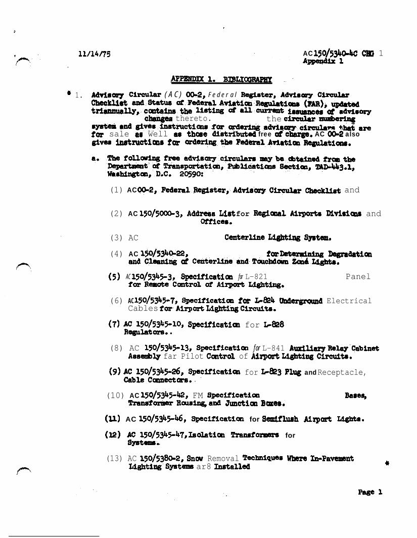
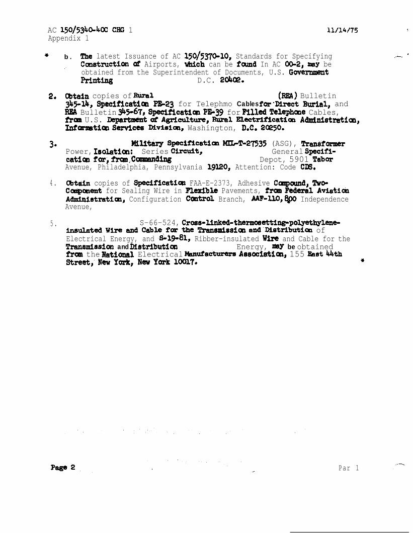
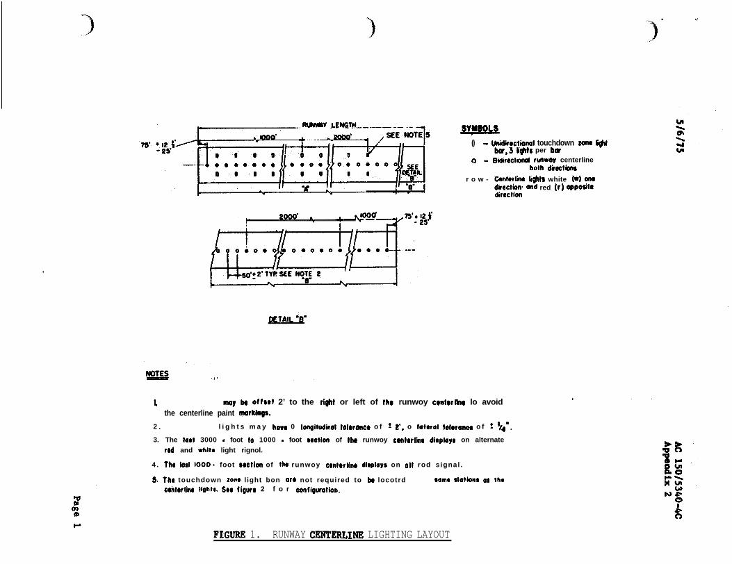
-
-
touchdown per
0 centerline
bbI whit
r o w - white red
Conterlinr light8 2rsquo to the or left of runwoy lo avoid the centerline paint
2 Thr crntorlinr l i g h t s m a y 0 o f o o f
3 The 3000 foot 1000 foot of runwoy on alternate and light rignol
4 foot of runwoy on rod signal
touchdown light bon not required to locotrd at thr 2 f o r
1 RUNWAY LIGHTING LAYOUT
S9 NVHL I O N 0 1
3 8
V N I
- - - - -
o f
-
~
BASE VARIES
AR
BASE AND OR SUBBASE
ANCHOR
3 SECTION THROUGH BASE AND ANCHOR BASE AND
AC 1 Appendix 2
JIG FOR ALIGNING BASE I
PC CONCRETE ANCHOR
AOJUSTABLE BAR CAGE
SUBBASE
NOTE
COVER PLATE SHOWN FOR ILLUSTRATION ONLY USE OF MUD PLATES CONSTRUCTION RINGS EXTENSIONS ON PAVING
Page 4
rsquo
1
PAVEMENTshy
PLATE SHOWN FOR ONLY USE MUD PLATES RINGS ON
I
L-550 FIXTURE
L-057 BASE
ASPHALT
BASE AND OR L- 555ASE
VARIES
f
VARIES
)
pnee
FIGURE
I2W Itmiddot
bullc-c middot---middot
NL bull
r n-
)
=n
011 bull fll --
- lfiiCifle1 bull ~ __ ltllt_ _ - - -_
bull _ OttbullY __ _ Wtrbull
INSTAIIATIW pErAILS FOil ToucHDOWN ZONE AND CENTERLINE LlGJflS
7 TYPICALWIREWAY
--
-
-
and
JOINT
DE TAIL
NOTES
w i r e s l e s s t h a n below sea t compound s e e S e c t i o n s A A and f o r d i m e n s i o n s
2 d i m e n s i o n s o f cored hole f o r - 8 5 0 f i x t u r e D e p t h
8 TYPICAL INSTALLATUJN DETAILS INSET LIGHTING FIXTURES
-
Appendix 2
HOUSING INSTALLATION
C U L L
SECTION 0
ARE INSTALLED IN WITH L-106
STANDARDS FOR OF
CONNECTORS-NUMBERS REFER TO L
NUMBERS
TYPICAL XTKES - - -
0 Awe
TRANSFORMER CONNECTIONS
01 3lUl3Id
and fobficote bon IO t h e f o o d i n speciftcaiti L- 850
Fill junction bon with o j u n c t i o n b o x l e v e l w i t h t h ei s t o prevenl waler f r o m h fhe junction b o r
t h e bar and t o oermit ins~ollotion amp v i c eProvide o ond grommets lo
b o a
FIGURE 11 JUNCTION BOX FOR INSET FIXTURE INSTALLATIONS
rsquo
lsquo
l
REGULATOR LOCATED
IN VAULT LIGHTS
W A T l S L - 6 5 0 T Y P E A
L - 8 2 8
SERIES LOOP
CENTERLINE ZONE]
CONSTANT CURRENT
REGULATOR LOCATED IN VAULT I TRANSFORMER L-830
200 WATTS IN L -657 BASE
F IXTURE L-
2 0 0 W T Y P E
TOUCHOOWN ZONE1
LIGHTING FIXTURE 200
12 ONE LINE DIAGRAM SERIES LIGHTING
AC Appendix 2
I
L SrsquoLI-rsquo CONTROL PANEL IN TOWER
L -828
CONTROL 7 C U R R E N T WIRES SEE NOTE S T E P - T Y P E
REGULATOR WITH INTERNAL
PRIMARY OIL
ISW I
I rdquo
I
I
OUTPUT
F U S E D C U T O U T
I
LIGHTNING ARRESTOR
CUTOUT W I T H
REGULATOR)TO RUNWAYNOTE LIGHTING CIRCUIT
C I R C U I T U P A P P R O X 3 0 0 0 O R
D R O P I S N O T D R O P I S I N O R A T CORTROI TERYIRALLOU C O N T R O L S E U S E D
13 WIampG REGULATOR WITH CONTROL AND SWITCH
13
AC
NOTES
AS A ELECTRICAL INSTALLATION CONFORM TO APPLICABLE SECTIONS OF THE NATIONAL ELECTRICAL CODE
PANEL TOWER
REMOTE OIL SWITCH
H2 INPUT
L - 8 2 8 CONSTANT CURRENT STEP TYPE
WITH EXTERNAL PRIMARY OIL
SWITCH
O U T P U T
ARRESTOR SEE NOTE 4
LIGHTNING ARRESTOR SEE NOTE4
7 WIRES SEE NOTE
AND CODES
2 MAY SE USED SEE NOTE I FIGURE
WHEN COUNTERPOISE IS IT INSTALLED IN ACCORDANCE WITH ITEM OF STANDARDS FOR SPECIFYING CONSTRUCTION OF AIRPORTS
4 ARRESTORS FURNISHED REGULATOR
FUSED CUTOUT-
14 TYPICAL REGULATOR WITH CONTROL POWER MD PRIMARY OIL SWITCH
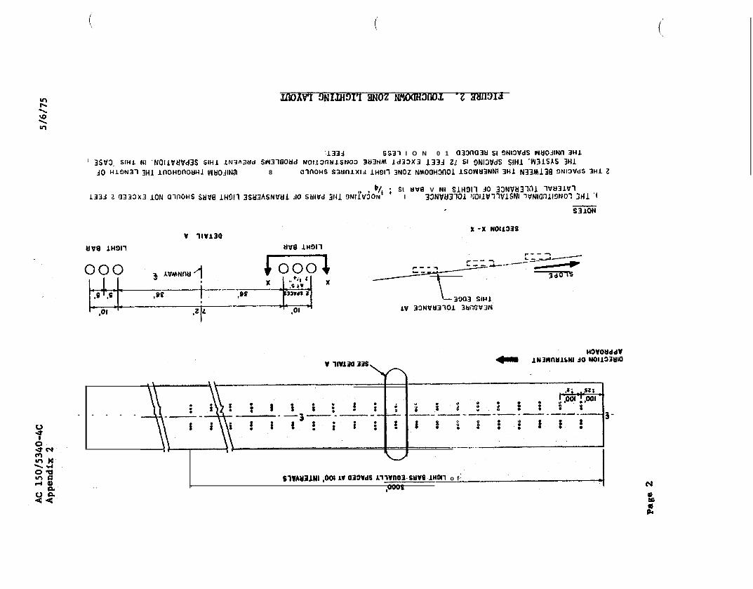
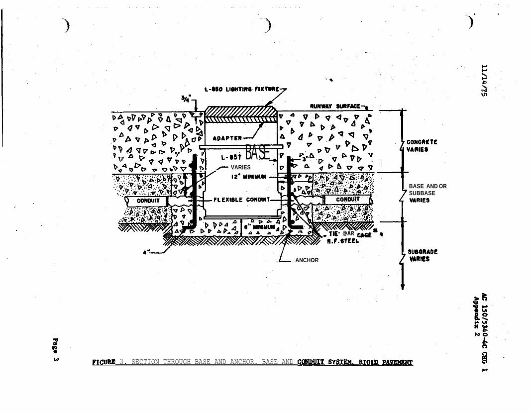
-
~
BASE VARIES
AR
BASE AND OR SUBBASE
ANCHOR
3 SECTION THROUGH BASE AND ANCHOR BASE AND
AC 1 Appendix 2
JIG FOR ALIGNING BASE I
PC CONCRETE ANCHOR
AOJUSTABLE BAR CAGE
SUBBASE
NOTE
COVER PLATE SHOWN FOR ILLUSTRATION ONLY USE OF MUD PLATES CONSTRUCTION RINGS EXTENSIONS ON PAVING
Page 4
rsquo
1
PAVEMENTshy
PLATE SHOWN FOR ONLY USE MUD PLATES RINGS ON
I
L-550 FIXTURE
L-057 BASE
ASPHALT
BASE AND OR L- 555ASE
VARIES
f
VARIES
)
pnee
FIGURE
I2W Itmiddot
bullc-c middot---middot
NL bull
r n-
)
=n
011 bull fll --
- lfiiCifle1 bull ~ __ ltllt_ _ - - -_
bull _ OttbullY __ _ Wtrbull
INSTAIIATIW pErAILS FOil ToucHDOWN ZONE AND CENTERLINE LlGJflS
7 TYPICALWIREWAY
--
-
-
and
JOINT
DE TAIL
NOTES
w i r e s l e s s t h a n below sea t compound s e e S e c t i o n s A A and f o r d i m e n s i o n s
2 d i m e n s i o n s o f cored hole f o r - 8 5 0 f i x t u r e D e p t h
8 TYPICAL INSTALLATUJN DETAILS INSET LIGHTING FIXTURES
-
Appendix 2
HOUSING INSTALLATION
C U L L
SECTION 0
ARE INSTALLED IN WITH L-106
STANDARDS FOR OF
CONNECTORS-NUMBERS REFER TO L
NUMBERS
TYPICAL XTKES - - -
0 Awe
TRANSFORMER CONNECTIONS
01 3lUl3Id
and fobficote bon IO t h e f o o d i n speciftcaiti L- 850
Fill junction bon with o j u n c t i o n b o x l e v e l w i t h t h ei s t o prevenl waler f r o m h fhe junction b o r
t h e bar and t o oermit ins~ollotion amp v i c eProvide o ond grommets lo
b o a
FIGURE 11 JUNCTION BOX FOR INSET FIXTURE INSTALLATIONS
rsquo
lsquo
l
REGULATOR LOCATED
IN VAULT LIGHTS
W A T l S L - 6 5 0 T Y P E A
L - 8 2 8
SERIES LOOP
CENTERLINE ZONE]
CONSTANT CURRENT
REGULATOR LOCATED IN VAULT I TRANSFORMER L-830
200 WATTS IN L -657 BASE
F IXTURE L-
2 0 0 W T Y P E
TOUCHOOWN ZONE1
LIGHTING FIXTURE 200
12 ONE LINE DIAGRAM SERIES LIGHTING
AC Appendix 2
I
L SrsquoLI-rsquo CONTROL PANEL IN TOWER
L -828
CONTROL 7 C U R R E N T WIRES SEE NOTE S T E P - T Y P E
REGULATOR WITH INTERNAL
PRIMARY OIL
ISW I
I rdquo
I
I
OUTPUT
F U S E D C U T O U T
I
LIGHTNING ARRESTOR
CUTOUT W I T H
REGULATOR)TO RUNWAYNOTE LIGHTING CIRCUIT
C I R C U I T U P A P P R O X 3 0 0 0 O R
D R O P I S N O T D R O P I S I N O R A T CORTROI TERYIRALLOU C O N T R O L S E U S E D
13 WIampG REGULATOR WITH CONTROL AND SWITCH
13
AC
NOTES
AS A ELECTRICAL INSTALLATION CONFORM TO APPLICABLE SECTIONS OF THE NATIONAL ELECTRICAL CODE
PANEL TOWER
REMOTE OIL SWITCH
H2 INPUT
L - 8 2 8 CONSTANT CURRENT STEP TYPE
WITH EXTERNAL PRIMARY OIL
SWITCH
O U T P U T
ARRESTOR SEE NOTE 4
LIGHTNING ARRESTOR SEE NOTE4
7 WIRES SEE NOTE
AND CODES
2 MAY SE USED SEE NOTE I FIGURE
WHEN COUNTERPOISE IS IT INSTALLED IN ACCORDANCE WITH ITEM OF STANDARDS FOR SPECIFYING CONSTRUCTION OF AIRPORTS
4 ARRESTORS FURNISHED REGULATOR
FUSED CUTOUT-
14 TYPICAL REGULATOR WITH CONTROL POWER MD PRIMARY OIL SWITCH
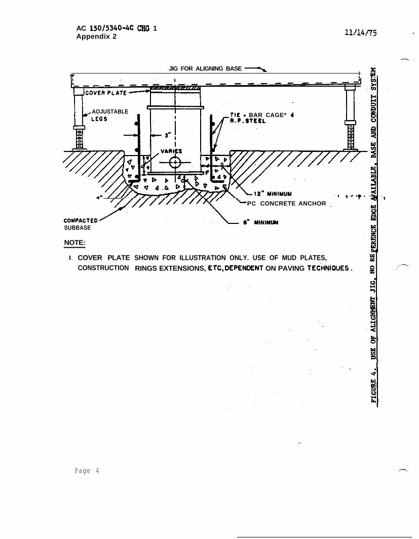
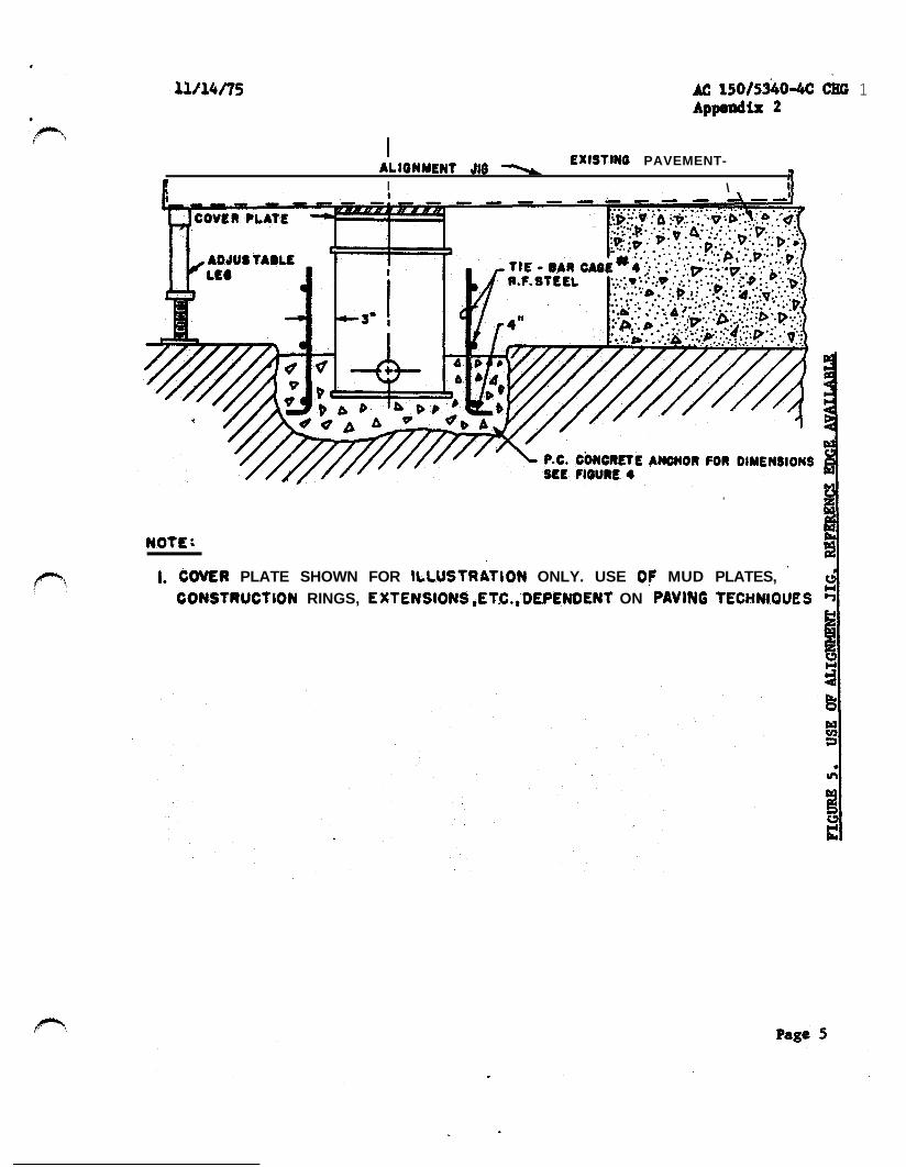
rsquo
1
PAVEMENTshy
PLATE SHOWN FOR ONLY USE MUD PLATES RINGS ON
I
L-550 FIXTURE
L-057 BASE
ASPHALT
BASE AND OR L- 555ASE
VARIES
f
VARIES
)
pnee
FIGURE
I2W Itmiddot
bullc-c middot---middot
NL bull
r n-
)
=n
011 bull fll --
- lfiiCifle1 bull ~ __ ltllt_ _ - - -_
bull _ OttbullY __ _ Wtrbull
INSTAIIATIW pErAILS FOil ToucHDOWN ZONE AND CENTERLINE LlGJflS
7 TYPICALWIREWAY
--
-
-
and
JOINT
DE TAIL
NOTES
w i r e s l e s s t h a n below sea t compound s e e S e c t i o n s A A and f o r d i m e n s i o n s
2 d i m e n s i o n s o f cored hole f o r - 8 5 0 f i x t u r e D e p t h
8 TYPICAL INSTALLATUJN DETAILS INSET LIGHTING FIXTURES
-
Appendix 2
HOUSING INSTALLATION
C U L L
SECTION 0
ARE INSTALLED IN WITH L-106
STANDARDS FOR OF
CONNECTORS-NUMBERS REFER TO L
NUMBERS
TYPICAL XTKES - - -
0 Awe
TRANSFORMER CONNECTIONS
01 3lUl3Id
and fobficote bon IO t h e f o o d i n speciftcaiti L- 850
Fill junction bon with o j u n c t i o n b o x l e v e l w i t h t h ei s t o prevenl waler f r o m h fhe junction b o r
t h e bar and t o oermit ins~ollotion amp v i c eProvide o ond grommets lo
b o a
FIGURE 11 JUNCTION BOX FOR INSET FIXTURE INSTALLATIONS
rsquo
lsquo
l
REGULATOR LOCATED
IN VAULT LIGHTS
W A T l S L - 6 5 0 T Y P E A
L - 8 2 8
SERIES LOOP
CENTERLINE ZONE]
CONSTANT CURRENT
REGULATOR LOCATED IN VAULT I TRANSFORMER L-830
200 WATTS IN L -657 BASE
F IXTURE L-
2 0 0 W T Y P E
TOUCHOOWN ZONE1
LIGHTING FIXTURE 200
12 ONE LINE DIAGRAM SERIES LIGHTING
AC Appendix 2
I
L SrsquoLI-rsquo CONTROL PANEL IN TOWER
L -828
CONTROL 7 C U R R E N T WIRES SEE NOTE S T E P - T Y P E
REGULATOR WITH INTERNAL
PRIMARY OIL
ISW I
I rdquo
I
I
OUTPUT
F U S E D C U T O U T
I
LIGHTNING ARRESTOR
CUTOUT W I T H
REGULATOR)TO RUNWAYNOTE LIGHTING CIRCUIT
C I R C U I T U P A P P R O X 3 0 0 0 O R
D R O P I S N O T D R O P I S I N O R A T CORTROI TERYIRALLOU C O N T R O L S E U S E D
13 WIampG REGULATOR WITH CONTROL AND SWITCH
13
AC
NOTES
AS A ELECTRICAL INSTALLATION CONFORM TO APPLICABLE SECTIONS OF THE NATIONAL ELECTRICAL CODE
PANEL TOWER
REMOTE OIL SWITCH
H2 INPUT
L - 8 2 8 CONSTANT CURRENT STEP TYPE
WITH EXTERNAL PRIMARY OIL
SWITCH
O U T P U T
ARRESTOR SEE NOTE 4
LIGHTNING ARRESTOR SEE NOTE4
7 WIRES SEE NOTE
AND CODES
2 MAY SE USED SEE NOTE I FIGURE
WHEN COUNTERPOISE IS IT INSTALLED IN ACCORDANCE WITH ITEM OF STANDARDS FOR SPECIFYING CONSTRUCTION OF AIRPORTS
4 ARRESTORS FURNISHED REGULATOR
FUSED CUTOUT-
14 TYPICAL REGULATOR WITH CONTROL POWER MD PRIMARY OIL SWITCH
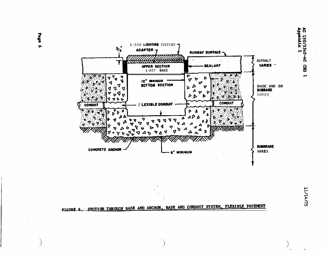
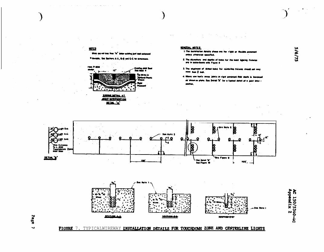
)
pnee
FIGURE
I2W Itmiddot
bullc-c middot---middot
NL bull
r n-
)
=n
011 bull fll --
- lfiiCifle1 bull ~ __ ltllt_ _ - - -_
bull _ OttbullY __ _ Wtrbull
INSTAIIATIW pErAILS FOil ToucHDOWN ZONE AND CENTERLINE LlGJflS
7 TYPICALWIREWAY
--
-
-
and
JOINT
DE TAIL
NOTES
w i r e s l e s s t h a n below sea t compound s e e S e c t i o n s A A and f o r d i m e n s i o n s
2 d i m e n s i o n s o f cored hole f o r - 8 5 0 f i x t u r e D e p t h
8 TYPICAL INSTALLATUJN DETAILS INSET LIGHTING FIXTURES
-
Appendix 2
HOUSING INSTALLATION
C U L L
SECTION 0
ARE INSTALLED IN WITH L-106
STANDARDS FOR OF
CONNECTORS-NUMBERS REFER TO L
NUMBERS
TYPICAL XTKES - - -
0 Awe
TRANSFORMER CONNECTIONS
01 3lUl3Id
and fobficote bon IO t h e f o o d i n speciftcaiti L- 850
Fill junction bon with o j u n c t i o n b o x l e v e l w i t h t h ei s t o prevenl waler f r o m h fhe junction b o r
t h e bar and t o oermit ins~ollotion amp v i c eProvide o ond grommets lo
b o a
FIGURE 11 JUNCTION BOX FOR INSET FIXTURE INSTALLATIONS
rsquo
lsquo
l
REGULATOR LOCATED
IN VAULT LIGHTS
W A T l S L - 6 5 0 T Y P E A
L - 8 2 8
SERIES LOOP
CENTERLINE ZONE]
CONSTANT CURRENT
REGULATOR LOCATED IN VAULT I TRANSFORMER L-830
200 WATTS IN L -657 BASE
F IXTURE L-
2 0 0 W T Y P E
TOUCHOOWN ZONE1
LIGHTING FIXTURE 200
12 ONE LINE DIAGRAM SERIES LIGHTING
AC Appendix 2
I
L SrsquoLI-rsquo CONTROL PANEL IN TOWER
L -828
CONTROL 7 C U R R E N T WIRES SEE NOTE S T E P - T Y P E
REGULATOR WITH INTERNAL
PRIMARY OIL
ISW I
I rdquo
I
I
OUTPUT
F U S E D C U T O U T
I
LIGHTNING ARRESTOR
CUTOUT W I T H
REGULATOR)TO RUNWAYNOTE LIGHTING CIRCUIT
C I R C U I T U P A P P R O X 3 0 0 0 O R
D R O P I S N O T D R O P I S I N O R A T CORTROI TERYIRALLOU C O N T R O L S E U S E D
13 WIampG REGULATOR WITH CONTROL AND SWITCH
13
AC
NOTES
AS A ELECTRICAL INSTALLATION CONFORM TO APPLICABLE SECTIONS OF THE NATIONAL ELECTRICAL CODE
PANEL TOWER
REMOTE OIL SWITCH
H2 INPUT
L - 8 2 8 CONSTANT CURRENT STEP TYPE
WITH EXTERNAL PRIMARY OIL
SWITCH
O U T P U T
ARRESTOR SEE NOTE 4
LIGHTNING ARRESTOR SEE NOTE4
7 WIRES SEE NOTE
AND CODES
2 MAY SE USED SEE NOTE I FIGURE
WHEN COUNTERPOISE IS IT INSTALLED IN ACCORDANCE WITH ITEM OF STANDARDS FOR SPECIFYING CONSTRUCTION OF AIRPORTS
4 ARRESTORS FURNISHED REGULATOR
FUSED CUTOUT-
14 TYPICAL REGULATOR WITH CONTROL POWER MD PRIMARY OIL SWITCH
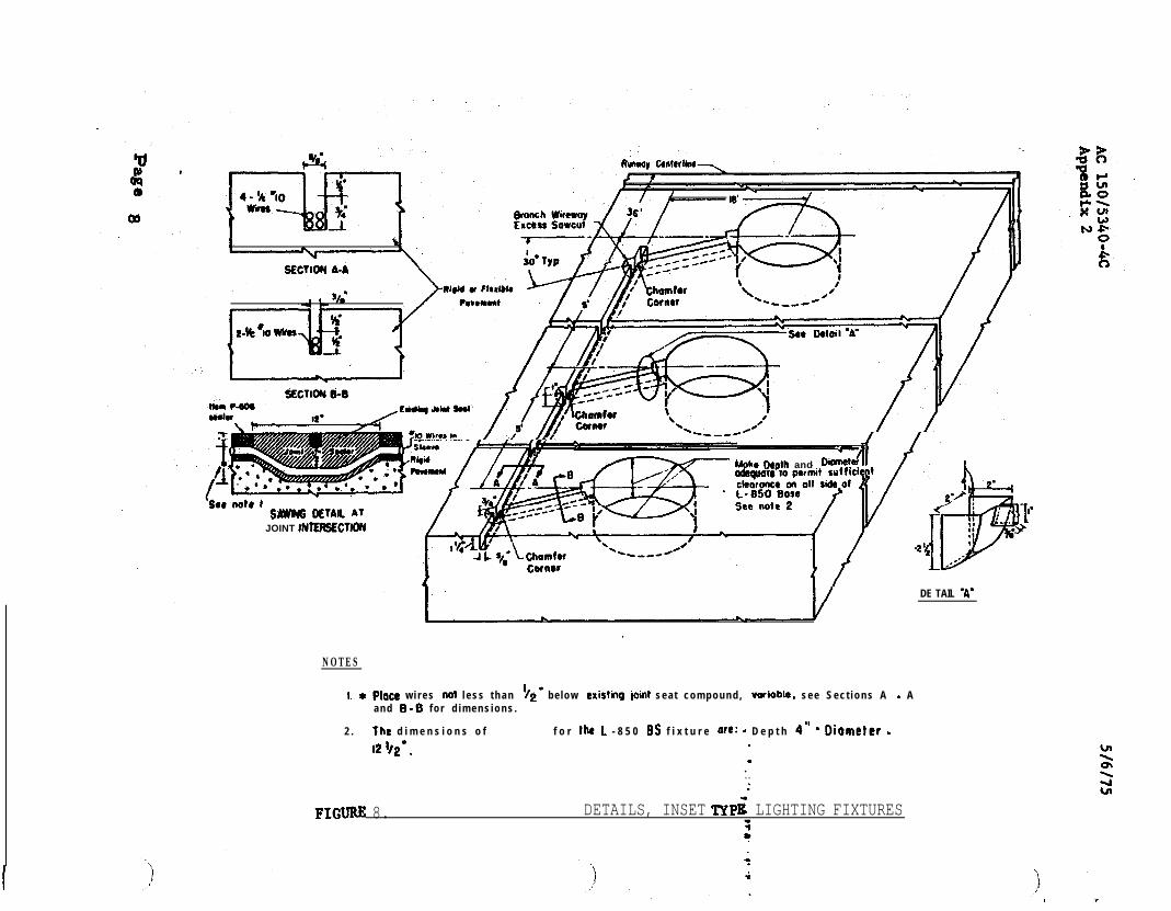
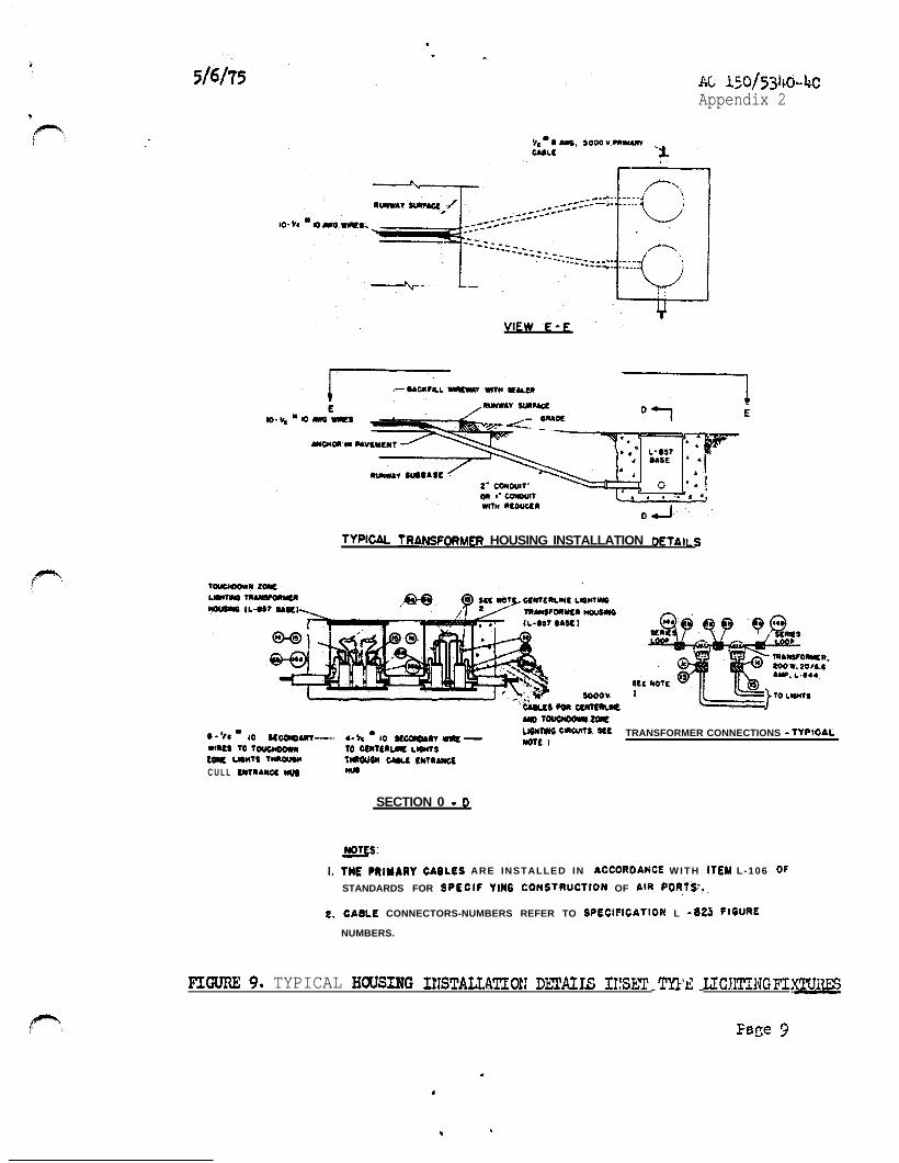
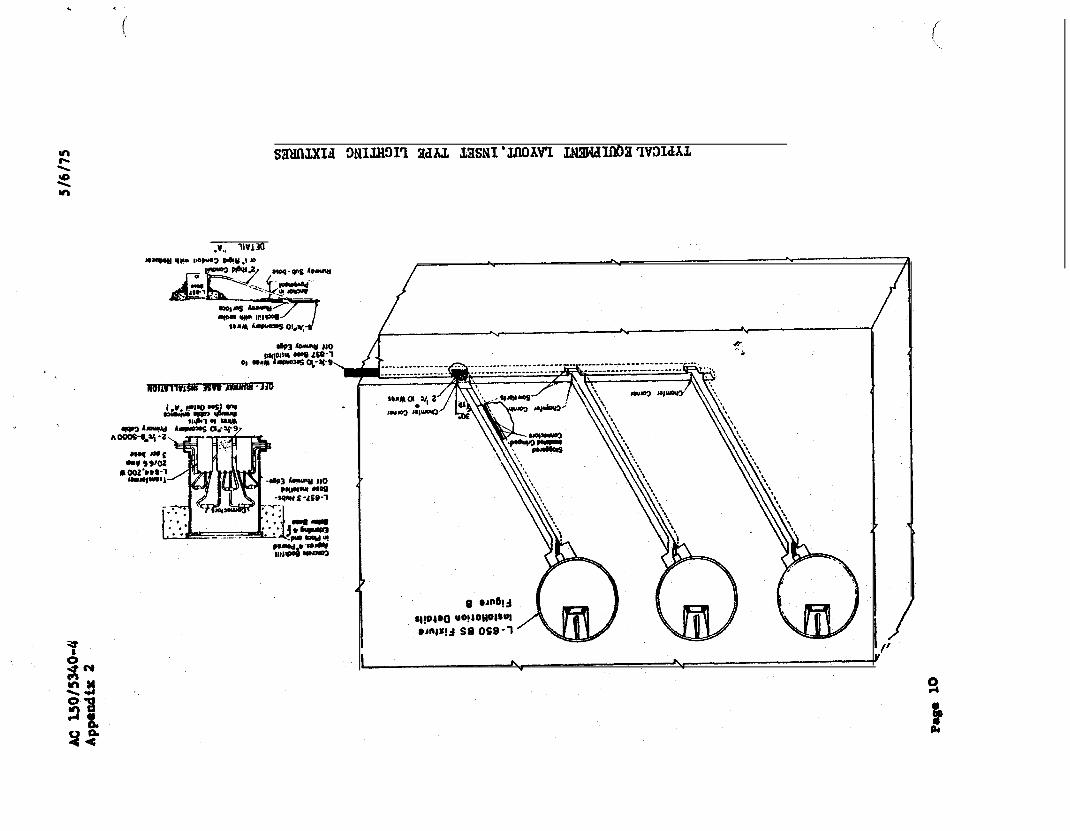
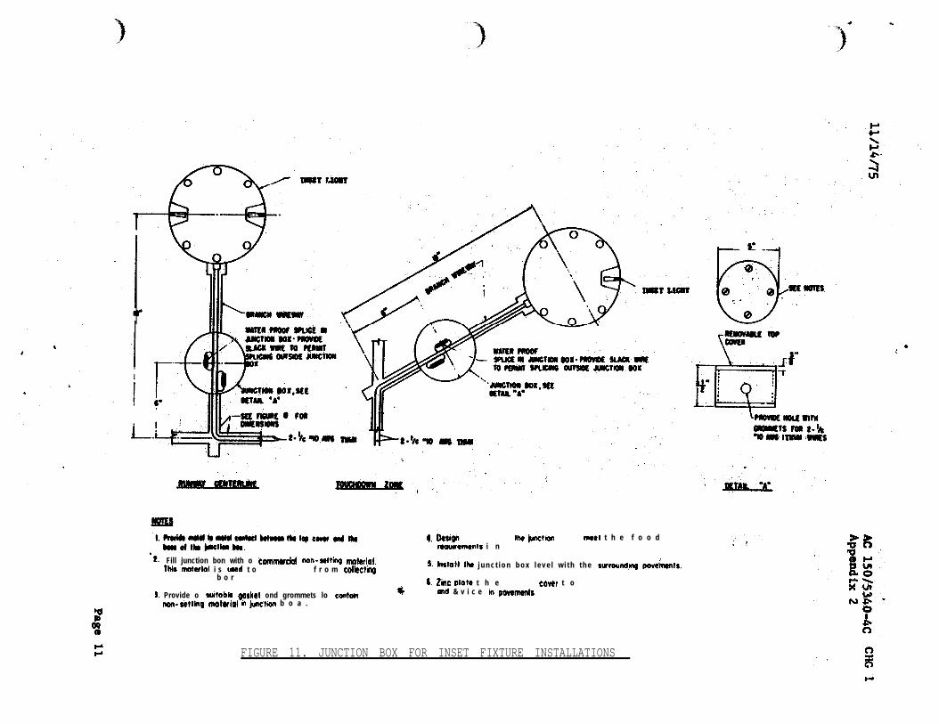
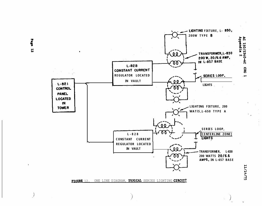
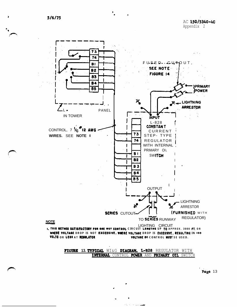
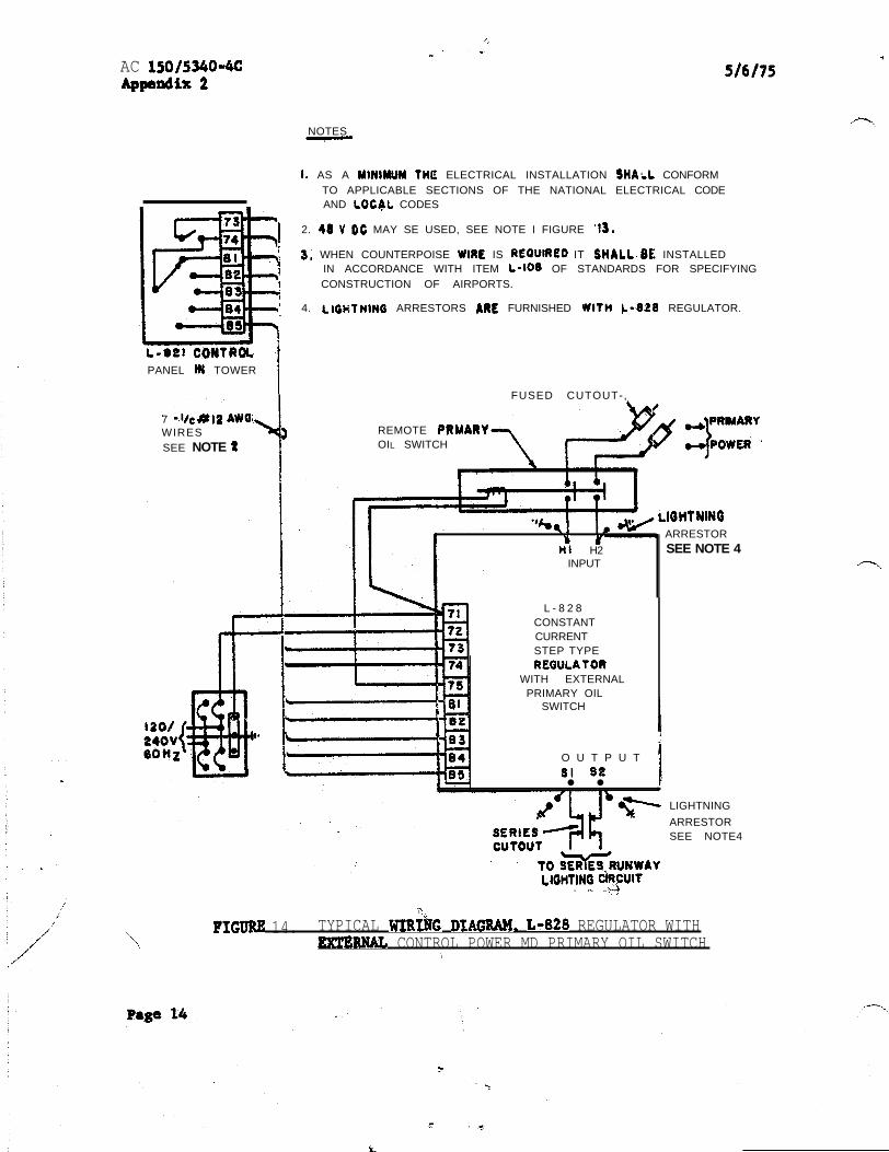