Embed Size (px)
Citation preview
AC Circuits
Physics 102Professor Lee
CarknerLecture 24

PAL #23 Alternating Current 240 lightbulb, Vrms = 120 V, 60 Hz
the rms current Vrms = IrmsR, Irms = Vrms/R = 120/240 =
the maximum current Imax = (2)½Irms = (2)½(0.5) =
the maximum power Pmax = I2maxR = (0.707)2(240) =
the average power Pav = I2rmsR =(0.5)2(240) =
the power at time equals 1/120 second I = Imax sint = Imax sin(2ft) = Imax sin [(2)()(60)(120)-1] = P =
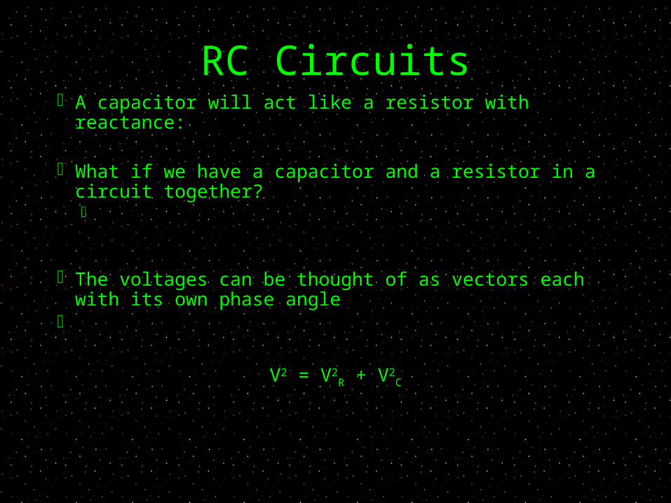
RC Circuits A capacitor will act like a resistor with reactance:
What if we have a capacitor and a resistor in a
circuit together?
The voltages can be thought of as vectors each with its own phase angle
V2 = V2R + V2
C
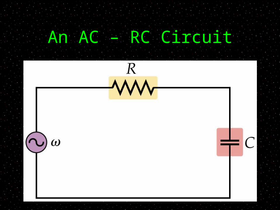
An AC – RC Circuit

Phase Diagram

Impedance We can write the voltages in terms of the currents:
If the resistor and the capacitor are in series they each have the same current, which we can factor out
We can rewrite as:
Where: Z = (R2 + X2
C)½
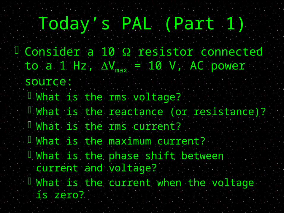
Today’s PAL (Part 1) Consider a 10 resistor connected to a
1 Hz, Vmax = 10 V, AC power source: What is the rms voltage? What is the reactance (or resistance)? What is the rms current? What is the maximum current? What is the phase shift between current
and voltage? What is the current when the voltage is
zero?
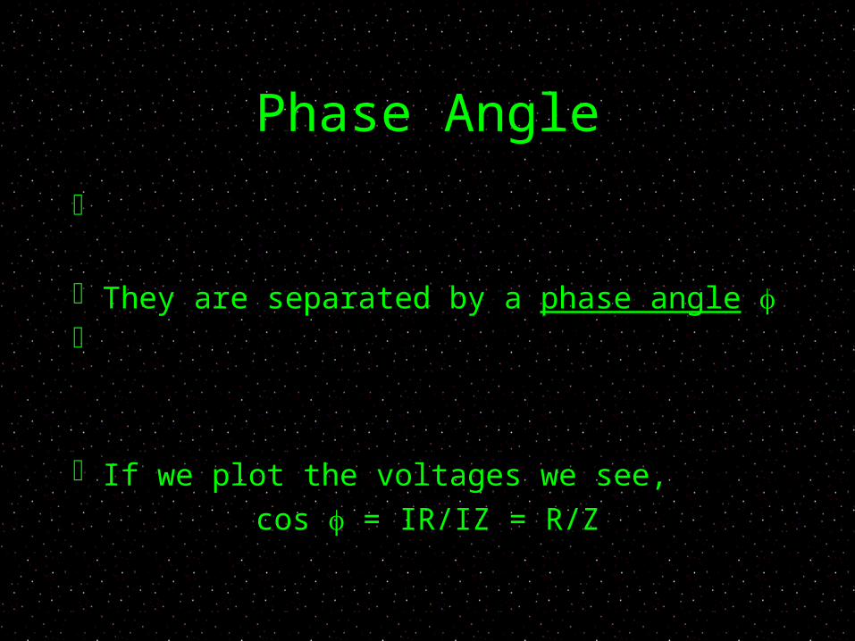
Phase Angle
They are separated by a phase angle
If we plot the voltages we see,cos = IR/IZ = R/Z
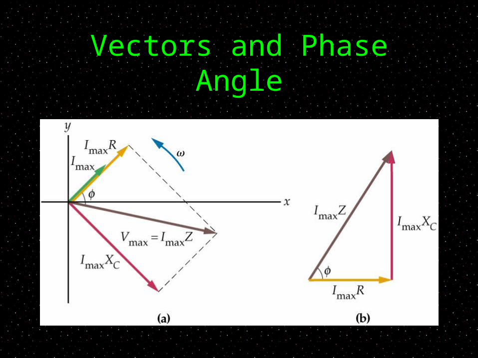
Vectors and Phase Angle

Phase and Power We know that power can be written P = IV
We can re-write power in terms of by using:
R = Z cos
Pav = IrmsVrms cos The average power depends not just on the
magnitude of I and V but also their phase
If they are shifted 90 deg (/2) they “average” out to zero power

Phase and Resistance Since cos = R/Z, we can think of cos as
the ratio of resistance to the total impedance If cos is small, R is small relative to Z
However, we also know that if cos is large, power is large Only the resistor dissipates power in a RC circuit

V, I , and Power
Today’s PAL (Part 2) Consider a 10 F capacitor connected to
a 1 Hz, Vmax = 10 V, AC power source: What is the rms voltage? What is the reactance (or resistance)? What is the rms current? What is the maximum current? What is the phase shift between current
and voltage? What is the current when the voltage is
zero?
Inductors and AC
The changing current produces an induced back emf in the inductor (VL)
The induced voltage is maximum when the current is zero (since that is where it is changing the most)
The voltage leads the current by 90 degrees (V is max 1/4 cycle before I)

AC Circuit With Inductor

Inductive Reactance We can define the way in which an inductor
impedes the current with the inductive reactance:
XL = L
We can relate the current and the potential difference across the inductor with:
Compare to the capacitive reactance:
XC = 1/(C)

Reactance and Frequency

Phase for R, L and C The phase angle for a circuit with just one R, L or C
is as follows: For just resistor:
=
For just capacitor: = -
Voltage is max 1/4 cycle after current
For just inductor =
Voltage is max 1/4 before current

Today’s PAL (Part 3) Consider a 10 inductor connected to
a 1 Hz, Vmax = 10 V, AC power source: What is the rms voltage? What is the reactance (or resistance)? What is the rms current? What is the maximum current? What is the phase shift between current
and voltage? What is the current when the voltage is
zero?
RCL and AC
For a series circuit, all elements have a
common current If you combine a resistor, capacitor and
an inductor into one series circuit, they all will have the same current but all will have difference voltages at any one time

RLC Circuit

RLC Impedance
Z = (R2 + (XL - XC)2)½
The voltages for the inductor and capacitor are 180 degrees opposed and so subtract
V = IZ

Next Time
Read 21.14 Homework Ch 21, P 64, 65, 69, 70