Embed Size (px)
Citation preview

AC-DC Single Output Power Module

One module now contains the functions previously
only obtainable by combining a front-end module
with a high voltage input DC-DC converter. The
product is made using a wide range input AC-DC
front end function (harmonic current control and
power factor correction) and DC-DC back-end
(voltage conversion and isolation) in 1 package).
PFHC is provided, primary and secondary isolation
for better safety and wide input range. High
efficiency with up to 100 base plate temperatures.
(PFE500S-12, PFE500F-12: Up to 85)
By utilizing output current balancing function, parallel operation up to 6 units is possible.
ON/OFF Control. ON/OFF control is possible even there is no ON/OFF in input circuit. ON/OFF control circuit is in between primary & secondary isolation.
Inverter Operation Good signal
Auxiliary Supply available
It is possible to clear 6kV surge voltage in normal
and common mode (absorber is installed in the input
filter).
PFE series features offer many reliable solutionsThanks to its compact size and reduction in cost, power distribution is easier to construct than before. More over, high power density and N+1 redundant parallel operation increase the reliability. High base plate temperature and 6kV surge immunity level makes PFE series suitable to be used in harsh outdoor environment. After all, new functions are added to each models to give reliable solution to many market demands.
PFE Series
AC Input Regulated Output
12V,28V,48V
EMI Filter Load
【Application Example】
【Huge reduction in space】
(old product) (PFE Series)
PFHC (AC-DC Conversion) and DC-DCConversion Integrated in One Package.PFHC (AC-DC Conversion) and DC-DCConversion Integrated in One Package.
2-in-1 Design Concept
Enhanced Surge Immunity Level
Full Function (F type)
High Power Density:0.95/High Efficiency:89%/Input Voltage:85~265VAC
Solution to Serve Different Kinds of Market Demands

3・All contents are subject to change without notice.
PFE-F SERIES
Product Line up
AC-DC Single Output Power Module
PFE 500 F-12 / Model naming method
OptionBlank: standard typeT: mounting standφ3.3 (non-thread,through hole)FG: 1.5kVDC (output-base plate); 48V output only
Output voltageFunctionF: Full Function
Output powerSeries name
YEARS
warranty2
Output Voltage500W 1000W
Output Current Model Output Current Model12V 42A PFE500F-12 60A PFE1000F-1228V 18A PFE500F-28 36A PFE1000F-2848V 10.5A PFE500F-48 21A PFE1000F-48
Features PFHC &DC-DC conversion integrated in one package Wide input voltage range: 85-265VAC High power factor: 0.95, meet PFHC standard
(EN-61000-3-2) High efficiency: max. 86% Wide base plate temperatures: -40 to +100 Full function model N+1 Redundant parallel operation Current sharing (load current balancing) IOG (Inverter Operation Good signal) Auxiliary supply available ON/OFF control Power ON signal Built-in capacitor: ceramic capacitors only (high reli-
ability)
PFE-F.(AC85-265Vin)
UL60950-1 EN60950-1 Low Voltage DirectiveCSA C22.2 No.60950-1
This means that, in conformity with EU Directive 2002/95/EC, lead, cadmium, mercury, hexavalent chromium, and specific bromine-based flame retardants, PBB and PBDE, have not been used, except for ex-empted applications.
Conformity to RoHS Directive Applications

PFE500F
4 ・All contents are subject to change without notice.
PFE500F Specifications
(*1) At 100VAC/200VAC and maximum output power. (Baseplate Temperature = +25°C.) (*2) For cases where conformance to various safety specs (UL, CSA, EN) are required, input voltage range will be 100 - 240VAC(50/60Hz). (*3) Ratings - refer to Derating Curve on the right. (*4) Heatsink has to be chosen according to Instruction manual. (*5) External components are needed for operation. (Refer to basic connection and instruction manual.) (*6) Refer to Instruction manual. (*7) Ambient Temperature min=-40°C (*8) OVP reset : Line off or Control off. (Refer to instruction manual.)
Derating Curve
100
80
60
40
20
0-40 -20 0 20 40 60 80
Baseplate Temperature()
Load(%)
85100
PFE500F-12PFE500F-28、48
ITEMS/UNITS MODEL PFE500F-12 PFE500F-28 PFE500F-48
Input
Voltage Range (*2) (*5) V 85 - 265 VAC
Frequency (*2) Hz 47 - 63
Power Factor (*1)(*5) 0.95
Efficiency (Typ) (*1) % 81 / 83 84 / 86
Current (*1) A 6.8 / 3.4 6.4 / 3.2
Inrush Current (Typ) (*1)(*5) A 20 / 40 peak
Output
Nominal Voltage (*1) VDC 12 28 48
Maximum Current A 42 18 10.5
Maximum Power W 504
Voltage Setting Accuracy % +/-2
Maximum Line Regulation mV 48 56 96
Maximum Load Regulation mV 48 56 96
Maximum Ripple & Noise (*5) mVp-p 120 280 480
Voltage Adjustable Range % -20 / +20
Function
Over Current Protection 105% - 140% (Automatic recovery method)
Over Voltage Protection (*8) 125% - 145% (Inverter shutdown method)
Remote Sensing (*6) Possible
Remote ON/OFF Control (*6) Possible
Parallel Operation (*6) Possible
Series Operation (*6) Possible
Environment
Operating Temperature (*3)(*7) -40 - +85(Baseplate) -40 - +100(Baseplate)
Storage Temperature -40 - +100
Operating Humidity %RH 20 - 95 (No Dewdrop)
Storage Humidity %RH 10 - 95 (No Dewdrop)
Vibration At no operating, 10-55Hz (Sweep for 1min.)
Amplitude 0.825mm constant (Maximum 49.0m/s²) X,Y,Z 1 hour each
Shock 196.1m/s²
Cooling (*4) Conduction Cooled
Standards Safety Standards Approved by UL60950-1, CSA C22.2 No.60950-1, EN60950-1
IsolationWithstand Voltage
Input-Baseplate : 2.5kVAC, Input-Output : 3.0kVAC for 1min.
Output-Baseplate : 500VDC for 1min.
Isolation Resistance Output-Baseplate 500VDC more than 100MΩ (25°C,70%RH)
MechanicalWeight (Typ) g 300
Size (W x H x D) mm 70 x 12.7 x 122 (Refer to Outline Drawing)

PFE500F
5・All contents are subject to change without notice.
PFE500F Outline DrawingLC
AC(L) +V
-V
AUX-ON/OFF+ON/OFF
PC-S +S
TRIMIOGENACOM
MADE IN JAPANR
AC (L)
AC (N) PFE500F-48
AC-DC
+BC -BC
50/60HzOUTPUT:48V 10.5A
INPUT:100-240VAC 8A
-ON/OFF
AUX
+ON/OFF
PC
-S
COM
ENA
IOG
TRIM
+S
+V
-V
LC
AC(N)
+V
-V
AUX-ON/OFF+ON/OFF
PC-S +S
TRIMIOGENACOM
MADE IN JAPANR
BAR CODE
AC-DC
+BC -BC
0E N 5906
CL
12.7
12.0
5.78
5.0±
0.5
see note Asee note D see note C
see note E
see note B
29.73
70.0±0.5
59.7±0.5
R +BC -BC
5.26
15.0 15.0
54.12
111.8±0.5
122.0±0.5
2.54
2.54
9.93
12.0
2.54
2.54 3.7
2.54
5.78
Lot No. seal
+0.7
-0.3
NOTES:A: Model name, input voltage range, Nominal output voltage, Maximum output current, country of manufacture and safety marking (C-UL-US, BSI & CE marking) are shown here in accordance with the specifications.B: M3 tapped holes 4 for customer chassis mounting (FG). C: Output terminal : 2-Φ2D: Input and Intermediate terminal : 5-Φ1E: Signal pin (+S, -S, TRIM, ENA, IOG, AUX, +ON/OFF, -ON/OFF, PC, COM) : 10-0.64F: Unless otherwise specified dimensional tolerance : ±0.3

PFE500F
6 ・All contents are subject to change without notice.
Basic Connection
L=50mm
INPUT
OUTP
UT
++
+v+s
-s
PC
TRIM
ENA
IOGAUX
+ON/OFF-ON/OFF
COM
-v
AC(L)
AC(N)
BASE-
R +BC -BC
C9
C8
TFR1
F1
*1
*2,3
*2,3
*5
*2,3
*4
*5*6 *6
L1 L2
C2
C1
C3
C10
C11
C12
PLATE
C4
R1
C5C6
C7
C13
C14
C15
C16 C17
+
+
PFE500F
Input Filter(For VCCI-classA)
F1 AC250V 15A C12 2200pF
R1 0.5W 470kΩ C13 0.033uF
C1 AC250V 1uF (Film) C14 0.033uF
C2 2200pF
C15
12V: 25V 1000uF (Elec.)
C3 2200pF 28V: 50V 470uF (Elec.)
C4 AC250V 1uF (Film) 48V: 100V 220uF (Elec.)
C5 AC250V 1uF (Film) C16 100V 2.2uF (Ceramic)
C6 2200pF
C17
12V: 25V 1000uF (Elec.)
C7 2200pF 28V: 50V 470uF (Elec.)
C8 450V 1uF (Film) 48V: 100V 220uF (Elec.)
C9 450V 1uF (Film) TFR1 10Ω 139°C (Res., Thermal fuse)
C10 450V 390uF (Elec.) L1 6mH
C11 450V 390uF (Elec.) L2 6mH
(*1) Use an external fuse of fast blow type for each unit.
(*2) The allowable ripple current of capacitor must be more than 3A(rms).
(*3) Put this capacitor near the terminal as close as possible.
(*4) The maximum capacitance that can be used is less than 1200uF(Rated capacitance). Avoid the connection of capacitance which is more than above, else it will lead to module to damage.
(*5) The inrush current at AC throw in can be suppressed by the external Resistor (Built-in thermal fuse) connected between the R and +BC terminals.
(*6) If the ambient temperature is less than -20°C, use twice the recommended capacitor above.
(*7) Refer to instruction manual for further details.

PFE500F
7・All contents are subject to change without notice.
Block Diagram
PFHC DC/DC Converter R
AC(L)
AC(N)
+BC -BC
+V
+S
-S
PC
TRIM
ENA
IOG
AUX
+ON/OFF-ON/OFF
COM
-V
Output vo
ltage
detector
PFHC
& BPS
Control c
ircuit
DC-DC
Con
trol c
ircuit
Sec
onda
ryCon
trol
Iutput voltage
detector
Iutput v
oltage
detector(DC-DC
)
Boost v
oltage
detector
Bias pow
ersupply
Iutput current
detector OCP
Rec
tifier
Filte
r
Rec
tifier
Switc
hing
circ
uit
Outpu
t filte
r
OVP
OCP
OVP
OTP(PF
HC)
OTP(DC
-DC)
OCP
Inrush current
limiting circ
uit
PFHC circuit
Switching FrequencyPFHC circuit (fixed) : 100kHzDC/DC converter (fixed) : 230kHz (primary),460kHz (secondary)

PFE500F
8 ・All contents are subject to change without notice.
Sequence Time Chart
H
L
390VDC(typ)
H
L
H
L
H
L
H
L
IOG
ENA
AUX
ON/OFFComtrol
Input Voltage(AC)
(Boost Voltage)
Output Voltage
OVP Trip
OTP
Trip
BC Terminal Voltage
Input L
ine
ON
Contro
l OFF
Contro
l OFF
Contro
l OFF
Contro
l ON
Contro
l ON
Contro
l ON
Input L
ine
OFF
Input L
ine
ON
OCP
Active
OCP
Release
V* voltage level: Refer to Application Notes “13.Power ON Signal” section.

・All contents are subject to change without notice.
PFE1000F Specifications
PFE1000F
9
100
80
60
40
20
0-40 -20 0 20 40 60 80
Baseplate Temperature()
(720W) (1008W)
Load
(%)
Load
(%)
100
100
80
60
40
20
0-40 -20 0 20 40 60 80
Baseplate Temperature()
85 100
85VAC≦Vin<170VAC170VAC≦Vin<265VAC
(*1) At 100VAC/200VAC and maximum output power. (Baseplate Temperature = +25°C.) (*2) For cases where conformance to various safety specs (UL, CSA, EN) are required, input voltage range will be 100 - 240VAC(50/60Hz). (*3) External components are needed for operation. (Refer to basic connection and instruction manual.) (*4) Constant current limiting. (The unit automatically shutdown when left in OCP condition, with the output voltageless than the LVP level. Refer to instruction manual.) (*5) Reset : Line off or Control off. (Refer to instruction manual.) (*6) Refer to Instruction manual. (*7) Ambient Temperature min=-40°C (*8) Ratings - refer to Derating Curve. (*9) Heatsink has to be chosen according to Instruction manual.
Derating CurvePFE1000F-12 PFE1000F-28,48
ITEMS/UNITS MODEL PFE1000F-12 PFE1000F-28 PFE1000F-48
Input
Voltage Range (*2)(*3) V 85 - 265 VAC
Frequency (*2) Hz 47 - 63
Power Factor (*1)(*3) 0.95
Efficiency (Typ) (*1) % 80 / 82 84 / 86
Current (*1) A 9.8 / 4.8 13.6 / 6.6 13.4 / 6.5
Inrush Current (Typ) (*1)(*3) A 20 / 40 peak
Output
Nominal Voltage (*1) VDC 12 28 48
Maximum Current A 60 36 21
Maximum Power W 720 1008
Voltage Setting Accuracy % +/-2
Maximum Line Regulation mV 48 56 96
Maximum Load Regulation mV 48 56 96
Maximum Ripple & Noise (*3) mVp-p 120 280 480
Voltage Adjustable Range % -20 / +20
Function
Over Current Protection (*4)(*5) 105% - 140%
Over Voltage Protection (*5) 125% - 145% (Inverter shutdown method)
Remote Sensing (*6) Possible
Remote ON/OFF Control (*6) Possible
Parallel Operation (*6) Possible
Series Operation (*6) Possible
Environment
Operating Temperature (*7)(*8) -40 - +100(Baseplate)
Storage Temperature -40 - +100
Operating Humidity %RH 20 - 95 (No Dewdrop)
Storage Humidity %RH 10 - 95 (No Dewdrop)
Vibration At no operating, 10-55Hz (Sweep for 1min.)
Amplitude 0.825mm constant (Maximum 49.0m/s²) X,Y,Z 1 hour each
Shock 196.1m/s²
Cooling (*9) Conduction Cooled
IsolationWithstand Voltage
Input-Baseplate : 2.5kVAC, Input-Output : 3.0kVAC for 1min.
Output-Baseplate : 500VDC for 1min.
Isolation Resistance Output to Baseplate 500VDC more than 100MΩ (25°C,70%RH)
Standards Safety Standards Approved by UL60950-1, CSA60950-1, EN60950-1
MechanicalWeight (Typ) g 500
Size (W x H x D) mm 100 x 13.4 x 160 (Refer to Outline Drawing)

・All contents are subject to change without notice.
PFE1000F Outline Drawing
88.5±0.5
100.0±
0.5
148.5±0.5160.0±0.5
16.215.0 15.0 71.7
10.15
6.35
2.54
2.542.5
42.54 3.7
13.4±
0.55.0±
0.5
12.0
19.0
43.7
2.54
Lot No. seal
147.7±0.5
6.35
6.35
6.35
8.75
AC(N)
AC(L)
R +BC -BC
AUX-ON/OFF+ON/OFF
PC-S +S
TRIMIOGENACOM
73.7
10.42
±0.5
+S
TRIM
IOG
ENA
COM
R +BC -BCMADE IN JAPAN
AC (L)
AC (N) PFE1000F-48OUTPUT : 48V 21A
INPUT : 100-240VAC 16A 50/60Hz
BAR CODE
AC-DC
-V
+V+V
+V
-V
AUX
-ON/OFF
-V
+ON/OFF
PC
-S
-V-V-V
+V+V+V
0E N 5906
CL
C L
see note D see note Asee note E
see note C
see note B
NOTES:A: Model name, input voltage range, Nominal output voltage, Maximum output current, country of manufacture and safety marking (C-UL-US, BSI & CE marking) are shown here in accordance with the specifications.B: M3 tapped holes 4 for customer chassis mounting (FG). C: Output terminal : 6-Φ2D: Input and Intermediate terminal : 5-Φ2E: Signal pin (+S, -S, TRIM, ENA, IOG, AUX, +ON/OFF, -ON/OFF, PC, COM) : 10-0.64F: Unless otherwise specified dimensional tolerance : ±0.3
PFE1000F
10

・All contents are subject to change without notice.
Basic Connection
L=50mm
++
+v+s
-s
PC
TRIM
ENA
IOGAUX
+ON/OFF-ON/OFF
COM
-v
AC(L)
AC(N)
BASE-
R +BC -BC
C10
C9
TFR2
TFR1
F1
*1
*2,3
*2,3
*5
*2,3
*4
*4
*3*6 *6
L1 L2 L3
C2
C1
C3
C13
*4C12
*4C11
C14
PLATE
C4 C5
C6
C7
C15
C16
C17
C18 C19
+
+
C8R1
+
+
PFE1000F
*5
INPUT
OUTP
UT
Input Filter(For VCCI-classA)
F1 F25AH250V C15 0.033uF
C1 AC250V 1uF (Film) C16 0.033uF
C2 470pF
C17
12V:25V 1000uF (Elec.)
C3 470pF 28V:50V 470uF (Elec.)
C4 AC250V 1uF (Film) 48V:100V 220uF (Elec.)
C5 AC250V 1uF (Film) C18 100V 2.2uF (Ceramic)
C6 4700pF
C19
12V:25V 1000uF (Elec.)
C7 4700pF 28V:50V 470uF (Elec.)
C8 AC250V 1uF (Film) 48V:100V 220uF (Elec.)
C9 450V 1uF (Film) R1 0.5W470kΩC10 450V 1uF (Film) TFR1 5.1Ω139 (Res., Thermal fuse)
C11 450V 390uF (Elec.) TFR2 5.1Ω139 (Res., Thermal fuse)
C12 450V 390uF (Elec.) L1 2mH
C13 450V 390uF (Elec.) L2 2mH
C14 450V 390uF (Elec.) L3 2mH
(*1) Use an external fuse of fast blow type for each unit.
(*2) The allowable ripple current of capacitor must be more than 3A(rms).
(*3) Put this capacitor near the terminal as close as possible.
(*4) The maximum capacitance that can be used is less than 2300uF(Rated capacitance). Avoid the connection of capacitance which is more than above of else it will lead to module damage.
(*5) The inrush current at AC throw in can be suppressed by the external Resistor (Built-in thermal fuse) connected between the R and +BC terminals.
(*6) If the ambient temperature is less than -20°C, use twice the recommended capacitor above.
(*7) Refer to instruction manual for further details.
PFE1000F
11

・All contents are subject to change without notice.
Block Diagram
R
AC(L)
AC(N)
+BC -BC
+V
+S
-S
PC
TRIM
ENA
IOG
AUX
+ON/OFF-ON/OFF
COM
-V
PFHC DC/DC Converter
Output vo
ltage
detector
PFHC
& BPS
Control c
ircuit
DC-DC
Contro
l circ
uit
Secondary
Contro
l
Iutput voltage
detector
Iutpu
t volt
age
detector(DC-DC
)
Boost v
oltage
detector
Bias pow
ersupply
Iutput current
detector OCP
Rectifier
Filte
r
Rectifier
Switc
hing circ
uit
Output fi
lter
OVP
OCP
LVP
OVP
OTP(PF
HC)
OTP(DC
-DC)
OCP
Inrush current
limiting circ
uit
PFHC circuit
Switching FrequencyPFHC circuit (fixed) : 100kHzDC/DC converter (fixed) : 230kHz (primary),460kHz (secondary)
PFE1000F
12

・All contents are subject to change without notice.
Sequence Time Chart
H
L
OVP Trip Point
V*V**
V*
H
L
H
L
H
L
H
L
OCP Trip PointLVP Trip Point
IOG
ENA
AUX
ON/OFFComtrol
Input Voltage(AC)
(Boost Voltage)
Output Voltage
OVP Trip
LVP Trip
OTP
Trip
BC Terminal VoltageInput L
ine
ON
Contro
l OFF
Contro
l OFF
Contro
l OFF
Contro
l OFF
Contro
l ON
Contro
l ON
Contro
l ON
Contro
l ON
Input L
ine
OFF
Input L
ine
ON
OCP
Active
390VDC(typ)
V* voltage level: Refer to Application Notes “13.Power ON Signal” section.V** voltage level: Refer to Application Notes “6.Over Current Protection” section.
PFE1000F
13

・All contents are subject to change without notice.
PFE500F・1000F SERIES
14
PFE500F, 1000F SERIES Instruction Manual
Be sure to read this instruction manual thoroughly before using this product. Pay attention to all cautions and warnings before using this product. Incorrect usage could lead to an electrical shock, damage to the unit or a fire hazard
DANGER
Never use this product in locations where flammable gas or ignitable substances are present.
WARNING
Do not make unauthorized changes to power supply unit, oth-erwise you might have electric shock and void your warranty.
Do not touch this unit and the internal components in opera-tion or shortly after shut down. They might have high voltage or high temperature and as the unit dissipates its heat so the surface of the unit is hot. You might receive electric shock or burn.
When the unit is operating, keep your hands and face away from it; you might be injured by an accident.
Do not use unit under unusual condition such as emission of smoke or abnormal smell and sound etc. It might cause fire and electric shock. In such case, please contact us; do not repair by yourself, as it is dangerous for the user.
Do not drop or insert anything into unit. It might cause failure and fire.
Do not operate these units under condensation condition. It might cause fire and electric shock.
CAUTION
As a component part, compliance with the standard will be based upon installation in the final application. This product must be installed in a restricted access location, accessible to authorized competent personnel only. These AC to DC converters have reinforced insulation between the input and the output. The outputs of these products are energy haz-ards. All models with an output greater than 48V model are considered to be non-SELV. As such, the instructions for use must refer to these energy hazardous outputs and Non-SELV outputs in that the outputs must not be accessible to the operator. The installer must also provide protection against inadvertent contact by a service engineer.
The equipment has been evaluated for use in a Pollution De-gree 2 environment.
This power supply is primarily designed and manufactured to be used and enclosed in other equipment.
Confirm connections to input/output terminals and signal ter-minals are correct as indicated in the instruction manual.
Attach a fast acting external fuse to each module to ensure safety operation and compliance to each safety standard ap-proval. The recommended input fuse rating within the instruc-tions manual. The breaking capacity and voltage rating of this fuse might be subject to the end use application.
Input voltage, Output current, Output power, ambient temper-ature and ambient humidity should be used within specifica-tions, otherwise the unit will be damaged.
For application equipment, which requires very high reliability (Nuclear related equipment, traffic control equipment, medi-cal equipment, etc.), please provide fail safety function in the equipment.
Do not use the product in environment with strong electro-magnetic field, corrosive gas and conductive substance.
Do not operate and store this unit at an environment where condensation occurs. In such case, waterproof treatment is necessary
Never operate the unit under over current or shorted condi-tions for 30 seconds or more and out of Input Voltage Range as specification. Insulation failure, smoking, burning or other damage might occur to the unit.
The output voltage of this power supply unit is considered to be a hazardous energy level (The voltage is 2V or more and the electric power is 240VA or more). Prevention from direct contact with output terminal is highly necessary. While installing or servicing this power supply unit, avoid dropping tools by mistake or direct contact with output terminal. This might cause an electrical shock. While repairing this power supply unit, the AC input power must be switched off and the input and output voltage should be level.
To maintain the SELV output for outputs less than 28VDC, under fault conditions, the output must be connected to earth in the final application.
The application circuits and their parameter are for reference only. Be sure to verify effectiveness of application circuits and their parameters before finalizing circuit design.
Do not inject abnormal voltage to output terminal and signal terminal from the outside. The injection of reverse voltage or over voltage exceeding nominal output voltage to output ter-minals might cause damage to internal components.
This information in this document is subject to change with-out prior notice. For actual design-in, please refer to the lat-est publications of data sheet, etc., for the most up-to date specifications of the unit.
Design the board of an application circuit implementing this product in consideration of components layout, pattern layout and pattern width.
No part of this document might be copied or reproduced in any form without prior written consent of TDK-Lambda.
Note : CE MARKING
CE Marking when applied to a product covered by this handbook indicates compliance with the low voltage directive (2006/95/EC) in that it complies with EN60950-1.
BEFORE USING THE POWER SUPPLY UNIT

・All contents are subject to change without notice.
PFE500F・1000F SERIES
15
AC(N) -V
+VAC(L)
R +BC -BC
-SPC
+ON/OFF-ON/OFF
AUX
+STRIM
IOGENACOM
Name Plate
PFE500F Series
1. Terminal Explanation
[Input side terminals]
AC(L) : Input terminal live lineAC(N) : Input terminal neutral line
+BC : +Boost voltage terminal-BC : -Boost voltage terminalR : External inrush current limiting resistor terminal
[Output side terminals]
+V : +Output terminal-V : -Output terminal
+S : +Remote sensing terminal-S : -Remote sensing terminalPC : Output current balance terminalTRIM : Output voltage trimming terminalIOG : Inverter operation good terminalENA : Power on signal terminal+ON/OFF : +ON/OFF control terminal-ON/OFF : -ON/OFF control terminalAUX : Auxiliary power supply terminal for external circuitsCOM : Common ground terminal
・Baseplate can be connected to FG through M3 mounting tapped holes.・Consider contact resistance when connecting AC (L), AC (N), R, +BC, -BC, +V, -V. ・Note that +BC and -BC terminals is a primary voltage with high voltage (390VDC). Do not connect load to these terminals. It might result in power module damage.

・All contents are subject to change without notice.
AC(N)
-V-V-V
+V+V
+V
AC(L)
R +BC -BC
-SPC
+ON/OFF-ON/OFF
AUX
+STRIM
IOGENACOM
Name Plate
PFE1000F Series
PFE500F・1000F SERIES
16
[Input side terminals]
AC(L) : Input terminal live lineAC(N) : Input terminal neutral line
+BC : +Boost voltage terminal-BC : -Boost voltage terminalR : External inrush current limiting resistor terminal
[Output side terminals]
+V : +Output terminal-V : -Output terminal
+S : +Remote sensing terminal-S : -Remote sensing terminalPC : Output current balance terminalTRIM : Output voltage trimming terminalIOG : Inverter operation good terminalENA : Power on signal terminal+ON/OFF : +ON/OFF control terminal-ON/OFF : -ON/OFF control terminalAUX : Auxiliary power supply terminal for external circuitsCOM : Common ground terminal
・Baseplate can be connected to FG through M3 mounting tapped holes.・Consider contact resistance when connecting AC (L), AC (N), R, +BC, -BC, +V, -V. ・Note that +BC and -BC terminals is a primary voltage with high voltage (390VDC). Do not connect load to these terminals. It might result in power module damage.

・All contents are subject to change without notice.
1 Input Voltage RangeInput voltage range is indicated below. Take care not to apply input voltage which is above this specified range or under this specified range for more than 30 seconds. Nor
should a DC input voltage be applied as this would result into power module damage.
Input Voltage Range : Single Phase 85 to 265VAC Line Frequency Range : 47 to 63Hz
Basic Connection
Fig. 1-1-(1) Basic Connection for PFE500F Series
L=50mm
Load+
+
-
+
+V+S
-S
PC
TRIM
ENA
IOGAUX
+ON/OFF-ON/OFF
COM
-V
AC(L)
AC(N)
BASE-
R +BC -BC
C9
C8
TFR1
Fuse L1 L2
C2
C1
C3
C10
C11
C12
PLATE
C4 R1 C5C6
C7
C13
C14
C15
C16
C17
+
+
Input Filter(For VCCI-classA)
PFE500F
Fig. 1-1-(2) Basic Connection for PFE1000F Series
L=50mm
Load+
+
-
+
+V+S
-S
PC
TRIM
ENA
IOGAUX
+ON/OFF-ON/OFF
COM
-V
AC(L)
AC(N)
BASE-
R +BC -BC
C110
C109
Fuse L101 L102
C102
C101
C103
C111
C112
C114
C113
PLATE
C104 R101 C108
C106
C107
C115
C116
C117
C118
C119
+
+
+
+
Input Filter(For VCCI-classA)
L103
C105
PFE1000F
TFR101
TFR102
Note) To meet the surge immunity, evaluate the addition of the surge protection components. Refer to separate document“PFE500F Series IEC Data”and“PFE1000F Series IEC Data”.
PFE500F・1000F SERIES
17
2. Explanations on Specifications

・All contents are subject to change without notice.
F1 : External Input FuseThis power module has no internal fuse. Use external fuse to acquire each Safety Standard and to further improve safety. Further, Fast-Blow type fuse must be used per one module. Also, in-rush surge current flows during line throw-in. Be sure to check I2t capability of external switch and fuse.
Recommended External FusePFE500F : F15AH, 250VPFE1000F : F25AH, 250V
Note)Select fuse based on rated voltage, rated current and break-ing capacity.
(1)Voltage Ratings100VAC line : AC125V200VAC line : AC250V
(2)Current RatingsRated current is selected by the maximum input current based on operating conditions and can be calculated by the following formula.
Iin (max):Maximum Input CurrentPout : Maximum Output PowerVin : Minimum Input VoltageEff : EfficiencyPF : Power Factor
(3)Breaking CapacityThe breaking capacity may be subject to the end use application. Please select a suitably rated breaking capacity fuse for end use application.For Efficiency and Power Factor values, refer to separate document “PFE500F Series Evaluation Data” and “PFE1000F Series Evaluation Data”.
C1, C4, C5 : 1uF (Film Capacitor)C101, C104, C105, C108 : 1uF (Film Capacitor)Ripple current flows through this capacitor. When selecting capacitor, be sure to check the allowable maximum ripple current rating of this capacitor. Verify the actual ripple cur-rent flowing through this capacitor by doing actual mea-surement.
Recommended Voltage Rating : 250VAC
Note)Connect C5, C108 as near as possible towards the input terminals of this power module.
Audible noise may occur depending on type of film capaci-tor.
L1, L2 : 6mHL101, L102, L103 : 2mHAdd common mode choke coil to conform to EMI/EMS standard. When using multiple modules, connect coil to each module.Note) Depending on the input filter used, noise might increase or
power module might malfunction due to filter resonance.
C2, C3, C6, C7, C12: 2,200pF (Ceramic Capacitor)C102, C103 : 470pF (Ceramic Capacitor)C106, C107 : 4,700pF (Ceramic Capacitor)Connect ceramic capacitor to conform to EMI/EMS standard. Be sure to note the leakage current of your equipment when connecting this capacitor.High withstand voltage are applied across this capacitor de-pending on the application. Select capacitors with high with-stand voltage rating.
R1, R101 : 470kohmConnect bleeder resistor across AC(L) and AC(N) termi-nals.
C8, C9 : 1uF (Film Capacitor)C109, C110 : 1uF (Film Capacitor)Ripple current flows through this capacitor. When selecting capacitor, be sure to check the allowable maximum ripple current rating of this capacitor. Verify the actual ripple cur-rent flowing through this capacitor by doing actual mea-surement.
Recommended Voltage Rating : 450VDC
Note) Select Capacitor with more than 3A (rms) rating. Connect C8, C9, C109, C110 as near as possible towards the termi-nals of this power module.
C10, C11: 390uF (Electrolytic Capacitor) C111, C112, C113, C114 : 390uF (Electrolytic Capacitor) Refer to “Selection Method of External Bulk Capacitor for Boost Voltage”.Allowable External Capacitance at nominal capacitor val-ue is shown below.
Recommended Voltage Rating : 450VDC Recommended Total Capacitor : 390uF to 1,200uF (PFE500F Series) 780uF to 2,300uF (PFE1000F Series)
Note)1. Do not connect capacitors with more than the above capacitance value as this might result in power module damage.
2. When using module between 390uF ‒ 600uF for PFE500F Series, 780uF ‒ 1,200uF for PFE1000F Se-ries total capacitor value, it is necessary to reduce output power as shown in Fig1-3.
3. When using module below -20 deg C ambient temperature, AC ripple of boost voltage, output ripple voltage and start
up characteristics might be affected by ESR characteris-tics of the bulk capacitors.
Therefore, be sure to verify characteristics by actual evaluation.
C13, C14, C115, C116 : 0.033uFConnect ceramic or film capacitor to conform to EMI/EMS standard and to reduce output spike noise voltage.Note)High Voltage is applied across this capacitor during with-
stand voltage test depending on the application. Connect C13, C14, C115, C116 as near as possible to-
wards the terminals of this power module.
Iin (max)=Pout
Vin×Eff×PF(Arms) (Formula 1-1)
PFE500F・1000F SERIES
18

・All contents are subject to change without notice.
C15, C117 : Refer to Table 1-1To reduce output ripple voltage and to stabilize operation, connect electrolytic capacitors across +V and ‒V termi-nals.Note)Connect C15, C117 as near as possible to the +V and -V
terminals of this power module.
Vout C15 , C11712V 25V 1,000uF28V 50V 470uF48V 100V 220uF
Table 1-1 C15, C117:Recommended external capacitance
C16, C118 : 2.2uF (Ceramic Capacitor)Connect ceramic capacitor within 50mm from the output ter-minals +V and -V of the power module to reduce output spike noise voltage. Also, note that output spike noise voltage might vary depending on the wiring pattern of the printed circuit board.
C17, C119 : Refer to Table 1-2Connect C17, C119 within 50mm from the output termi-nals +V and -V of the power module to stabilize operation and to reduce output ripple noise voltage.Note that the output ripple and line turn off characteristics of the power module might be affected by the ESR and ESL of the electrolytic capacitor.Also, note that output ripple voltage might vary depending on the wiring pattern of the printed circuit board. Fluctuation in output voltage due to sudden load change or sudden input voltage change can be reduced by in-creasing external output capacitor value.
Vout C17 , C11912V 25V 1,000uF28V 50V 470uF48V 100V 220uF
Table 1-2 C17, C119:Recommended external capacitance
Note) 1. Use low-impedance electrolytic capacitors with excellent temperature characteristics.
(Nippon Chemi-con LXY Series or equivalent) (Nichicon PM Series or equivalent) 2. For module operation at ambient temperature -20 deg C
or less, output ripple voltage might be affected by ESR characteristics of the electrolytic capacitors. Increase the capacitor values shown in Table 1-1 and 1-2 according to the table below.
Vout C15 , C17 , C117 , C119
12V 25V 1,000uF x 2 parallel
28V 50V 470uF x 2 parallel
48V 100V 220uF x 2 parallel
Table 1-3 C15, C17, C117, C119 :Recommended external capacitance (Ambient Temperature < -20 deg C)
3. Take note of the allowable maximum ripple current of the electrolytic capacitor used. Especially, for sudden load current changes, verify actual ripple current and make sure that allowable maximum ripple current is not ex-ceeded.
Selection Method of External Bulk Capacitor for Boost Voltage
Boost voltage bulk capacitor is selected by ripple volt-age, ripple current and output hold-up time.
Select capacitor value such that boost voltage ripple voltage does not exceed 15Vp-p.
Note) When ambient temperature is -20 deg C or less, ripple voltage of the boost voltage might increase due to ESR characteristics. Therefore, verify above char-acteristics by actual evaluation.
For output hold-up time, refer to separate document “PFE500F Series Evaluation Data” or “PFE1000F Series Evaluation Data” and use appropriate capaci-tor up to 1,200uF maximum for PFE500F Series, 2,300uF maximum for PFE1000F Series. (It is rec-ommended that verification should be done through actual evaluation).
For allowable ripple current value, refer to Fig. 1-2 and select a capacitor with higher ripple current rating.
PFE500F・1000F SERIES
19

・All contents are subject to change without notice.
The recommended boost voltage bulk capacitor value range is 390uF-1,200uF for PFE500F Series, 780uF-2,300uF for PFE1000F Series. When using with reduced the bulk capacitor value, it is necessary to reduce output power as shown in Fig1-3. Note that reducing the bulk capacitance affects output hold-up time, dynamic line response and dynamic load re-sponse characteristics.It is recommended that verification should be done through actual evaluation.
TFR1 : 10 to 100 ohmTFR101, TFR102 : 10 to 50 ohm (Total value)By connecting resistor across R and +BC terminals as shown in Fig. 1-1, in-rush current during line throw-in can be sup-pressed. Failures due to in-rush current such as melting of external fuse, welding of relay or switch connecting joints or shutdown of No-Fuse Breakers (NFB) might occur. Therefore, select TFR1, TFR101, TFR102 in consideration of the surge current capability of the external components. (TFR1, TFR101, TFR102 are recommended to use the Thermal Fuse Resistor.)
Note) 1.Do not connect resistors that is out of range from the values shown above as this might result in power module damage.
2.Note that this module will not operate without this exter-nal resistor.
Selection Method of External Resistor(1)Calculating Resistance Value for External Resistor Resistance can be calculated by the formula below.
R : Resistance Value for External resistorVin : Input Voltage converted to DC value =Input Votlage (rms)×√2Irush : Input surge current value
(2)Required Surge Current Rating Sufficient surge current withstand capability is required for external resistor. Required Surge Current Rating can be selected by I2t. (Current squared multiplied by time)
I2t : Current-squared multiplied by timeCo : Boost Voltage Bulk CapacitanceVin : Input Voltage converted to DC value =Input Voltage (rms)×√2R : Resistance Value for External Resistor
2 Output Voltage Adjustment Range(TRIM terminal)Output voltage can be adjusted within the range below by connecting fixed and variable resistors or applying external
R=VinIrush
Ω (Formula 1-2)
I2t=Co×Vin2
2×R(A2s) (Formula 1-3)
PFE500F・1000F SERIES
20
100
80
60
40
20
00 200 400 600 800 1000 1200
Outpu
t Pow
er(%)
Bulk Cap.(uF)
390uF
1200uF
Tbp:25
2000
1600
1200
800
400
00 20 40 60 80 100
200VAC
100VAC
Ripple Current(mA rm
s)
Load Current(%)
2000
1600
1200
800
400
00 20 40 60 80 100
Ripple Current(mA rm
s)
Load Current(%)
200VAC
100VAC
100
80
60
40
20
00 500 1000 1500 2000 2500
780uF
2300uF
Tbp:25
Outpu
t Pow
er(%)
Bulk Cap.(uF)
Fig. 1-2-(1) Ripple current value for PFE500F Series(A value per one of Fig. 1-1-(1) connection)
Fig. 1-3-(1) Output Power v.s. Boost Voltage Bulk Capacitance For PFE500F Series
Fig. 1-2-(2) Ripple current value for PFE1000F Series(A value per one of Fig. 1-1-(2) connection)
Fig. 1-3-(2) Output Power v.s. Boost Voltage Bulk Capacitance For PFE1000F Series

・All contents are subject to change without notice.
voltage.However, take care not to exceed the output voltage range shown below because OVP function will activate.In the PFE1000F Series, be careful not to drop from the following range, because a Low Voltage Protection (LVP) function will be activate.
Output Voltage Adjustment Range :+/-20% of the typical voltage rating
When increasing or decreasing output voltage, it must not exceed maximum output current and power.Even if the output voltage is adjusted using external circuit shown in Fig. 2-1, remote sensing can be done. For details on Remote Sensing function, refer to“9. Remote Sens-ing”.
Output Voltage Adjustment using Fixed and Vari-able ResistorsExternal resistor (R1) and variable resistor (VR) values, as well as, circuit connection is shown below.For this case, remote programming of the output voltage can be done through the remote programming resistor VR. Be sure to connect the remote programming resistor be-tween +S and +V terminals
12V 28V 48VR1 18k 18k 18kVR 10k 20k 50k
unit:[ohm]External Resistor : Tolerance +/-5% or lessVariable Resistor : Total Tolerance +/-20% or less Remain Resistance 1% or less
Table 2-1External Resistor and Variable Resistor Value
(For +/-20% Output Adjustment)
Fig. 2-1 External Resistor Connection Example
Output Voltage Adjustment by applying external voltageBy applying external voltage at the TRIM terminal, output voltage can be adjusted within the same output voltage adjustment range as the output voltage adjustment by external resistor or variable resistor. For this case, output voltage can be determined by the formula shown below.
Output Voltage = TRIM Terminal Voltage x Nominal Output Voltage
Fig. 2-2 Output Voltage Adjustment by applying external voltage
For applications other than the above, refer to the TRIM circuit as shown in fig.2-3 and determine external circuit and components values.
Fig.2-3 Internal TRIM Circuit (For the Reference)
3 Maximum Ripple and NoiseThis value is measured according to the description below in accordance with JEITA-9131B(Section 7.16, 7.17 and 7.18).In the basic connection shown in Fig. 1-1, additional connection shown in Fig. 3-1 is done for measurement. Capacitor (Ceramic Capacitor : 2.2µF and Electrolytic Capacitor : Refer to Table 1-2) must be connected within 50mm from the output terminals. Then, connect coaxial cable with JEITA attachment across the ceramic capaci-tor electrodes. Use 100MHz bandwidth oscilloscope or equivalent. Also, note that output ripple voltage and output spike noise voltage might vary depending on the wiring pattern of the printed circuit board. In general, output ripple voltage and output spike noise voltage can be reduced by increasing external capaci-tance
Error amplifier+S
-S
1kΩ32.4kΩ
7.32kΩ
1.225VReferencevoltage
TRIM
+S
-S
+V
-V
TRIM
+ +
+
+
-
-
Load
PFE500F・1000F SERIES
21
+S
-S
+V
-V
VR
R1TRIM
+ +
+
-
Load

・All contents are subject to change without notice.
Fig. 3-1Output Ripple Voltage (including Spike Noise)
Measurement Method
4 Maximum Line RegulationMaximum line regulation is defined as the maximum output voltage change when input voltage is gradually changed (Steady-State) within specification range.
5 Maximum Load RegulationMaximum load regulation is defined as the maximum out-put voltage change when output load current is gradually changed (Steady-State) within specification range.When using power module in dynamic load mode, audible sound could be heard from the power module or large output voltage change might occur. Make prior evaluation thoroughly before using this power module.
6 Over Current Protection (OCP)This module is equipped with OCP function. Constant current limiting with automatic recovery for PFE500F Series. Output will automatically recover when short circuit or overload condition is released. Constant current limiting with delay shutdown for PFE1000F Series. Output will be shutdown when output about under 70 % by short circuit or overload condition that continue about 0.5s. When the shutdown function ac-tivates, first cut off input line and verify that boost voltage has dropped down to 20V or less. Then, recover output by recycling input line. In other method, reset to ON/OFF control. OCP value is fixed and cannot be adjusted exter-nally.Note that continuous short circuit or overload condition more than 30s, might result in power module damage.
7 Over Voltage Protection (OVP)This module is equipped with OVP function. This value is set between 125% to 145% of nominal output voltage.When the OVP function activates, first cut off input line and verify that boost voltage has dropped down to 20V or less. Then, recover output by recycling input line. In other method, reset to ON/OFF control. OVP value is fixed and cannot be set externally.
8 Over Temperature Protection (OTP)This module is equipped with OTP function. This func-tion activates and shuts down the output when ambient temperature or internal temperature abnormal rises. OTP activates at following baseplate temperature.
PFE500F-12 : 90 to 115 deg CPFE500F-28, 48 : 105 to 130 deg CPFE1000F-* : 105 to 130 deg C
When OTP function operates, output can be recovered by cooling down the baseplate sufficiently and letting the boost voltage drop down to 20V or less before recycling the input line. In other method, reset to ON/OFF control.
9 Remote Sensing (+S, -S terminals)This module has remote sensing terminals to compensate for voltage line drop from the output terminals to the output load. When remote sensing is not required, (local sensing) short +S to +V and -S to -V terminals respectively.Note that line drop (voltage drop due to wiring ) compen-sation voltage range must be such that the output voltage is within the output voltage adjustment range and that the voltage between -V and -S must be within 0.5V.Consider power loss due to line drop and use power mod-ule within the maximum allowable output power. Reduce the effect of noise to the remote sensing line by using a shield line, a twist pair, or a parallel pattern, etc.When remote sensing line is long, add the electrolytic ca-pacitor as shown in Fig 9-1.
Fig. 9-1 Remote Sensing is used
Fig. 9-2 Remote Sensing is not used (Local Sensing)
PFE500F・1000F SERIES
22
+S
-S
+V
-V
++
+
-
Load
Stabilize the output voltageat output terminal
+S
-S
+V
-V
++
+
-
Load
Stabilize the output voltageat load terminal
Twist pair
+
+
+
Wires must be as short as possible
+
+
+V
-V
+
-
Load
Oscilloscope
R:50ΩC:4700pF
C
R
JEITAAttachment
1.5m 50ΩCoaxial Cable50mm

・All contents are subject to change without notice.
10 ON/OFF Control (+ON/OFF, -ON/OFF terminal)This module is equipped with ON/OFF control function. Without turning the input supply on and off, the output can be enabled and disabled using this function.The ON/OFF control circuit is isolated from input circuit of the power supply by photo-coupler. Fig. 10-1 and Fig. 10-2 is connection example of ON/OFF control. When the ON/OFF control is not used, short +ON/OFF to AUX and -ON/OFF to COM terminals re-spectively.
Fig. 10-1 ON/OFF Control Connection Example 1(ON/OFF Control by External Voltage)
Select the external voltage and external resistance, as the ON/OFF terminals current is shown below.
ON/OFF terminal current Output Voltage2.5mA (+/-0.5mA) ONLess than 0.15mA OFF
Table 10-1 Recommended ON/OFF Terminal Current
Fig. 10-2 ON/OFF Control Connection Example 2(ON/OFF Control by Built-in AUX)
Fig. 10-3 ON/OFF Control Connection Example 3(ON/OFF Control is not used)
11 Series OperationSeries operation is possible for PFE500F Series and PFE1000F Series. Connections shown in Fig. 11-1 and Fig. 11-2 are possible.
Fig. 11-1 Series Operationfor High Output Voltage Applications
Fig. 11-2 +/-Output Series Applications
12 Parallel Operation (PC terminal)By connecting the PC terminal of each power module, output current can be equally drawn from each module. A maximum of 6 units of the same model can be connected.
AUX
COM
11V
+ON/OFF
4.7k
-ON/OFF
+S
+
+
+
-
Load
-S
+V
-V
+S
-S
+V
-V
+S
+
+
+
-
Load
+
-
Load
-S
+V
-V
+S
-S
+V
-V
PFE500F・1000F SERIES
23
AUX
COM
11V
+ON/OFF
4.7k
-ON/OFF
ON
RExternalvoltage
OFF
AUX
COM
11V
+ON/OFF
4.7k
-ON/OFF
ON
OFF

・All contents are subject to change without notice.
However, maximum output current is derated by parallel operation units as shown in Table 12-1.Note that usage of power module at out-of-rated condition might result in power module temperature abnormal rise or damage.
Parallel units Maximum output current~ 3 units 90% of nominal output current4 ~ 6 units 85% of nominal output current
Table 12-1 Condition for Parallel Operation
Set the accuracy of the output voltage within +/-1% when adjust the output voltage for parallel operation.When adjust the output voltage by applying external volt-age at the TRIM terminal, insert a about 10k ohm resistor between TRIM terminal and external source.Moreover, external circuits are necessary for TRIM termi-nal at each individual module.
Fig. 12-1 Output Voltage Adjustment by applying external voltage(For parallel operation)
At parallel operation, +BC, -BC and R terminals must not be connected in parallel with other modules. It might result in power module damage.Refer to “Parallel Operation” of the PH-Series Application Notes for details.
13 Power ON Signal (ENA terminal)This signal is located at the secondary side (output side) and it is an open collector output. (Maximum sink current is 10mA and maximum applied voltage is 75V.)Return line for ENA terminal is the COM terminal.When output voltage goes over a specified voltage level at start up, Power ON signal is LOW.Output voltage threshold level is as follows.
PFE500F・1000F-12 : 8V (TYP)PFE500F・1000F-28 : 19V (TYP)PFE500F・1000F-48 : 33V (TYP)
On the other hand, output voltage threshold level for Pow-er ON signal to turn HIGH is as follows.
PFE500F・1000F-12 : 6V (TYP)PFE500F・1000F-28 : 15V (TYP)PFE500F・1000F-48 : 28V (TYP)
14 I.O.G signal (IOG terminal)Normal or abnormal operation of the power module can be monitored by using the IOG terminal. Output of this signal monitor is located at secondary side (output side) and is an open collector output. This signal is LOW when inverter is normally operating and HIGH when inverter stops or when inverter is operating ab-normally. (maximum sink current is 5mA, maximum applied voltage is 35V)Ground for the IOG terminal is the COM terminal.Also note that IOG becomes unstable for following condi-tions:
・Operation of Over Current Protection (OCP)・Light load conditions at parallel operation・Dynamic load operation
15Auxiliary power supply for external circuits (AUX terminal)
For AUX terminal, output voltage value is within 10 ~14VDC range, maximum output current is 20mA. Ground for the AUX terminal is COM terminal. Avoid short circuit of AUX terminal with other terminals as this would lead to power module damage.
16 Operating Temperature RangeThese products can be used in any mounting direction but be sure to consider enough airflow to avoid heat accumu-lation around the module.Consider surrounding components layout and set the PCB mounting direction such that air can flow through the heat-sink by forced or convection cooling .This product can operate at actual mounting condition when baseplate temperature is maintained at or below the following baseplate temperature.
PFE500F-12:85PFE500F-28,48:100PFE1000F-12:100PFE1000F-28,48:85(85VAC≦Vin<170VAC) 100(170VAC≦Vin≦ 265VAC)
Verify baseplate temperature at worst case operating con-dition at the measuring point as shown in Fig. 16-1.For Thermal Design details, refer to Power Module Appli-cation Notes “Thermal Design” section.
PFE500F・1000F SERIES
24
-
+S
-S
+V
-V
TRIM
PC
+
+
+
+
-
Load

・All contents are subject to change without notice.
100
80
60
40
20
0
-40 -20 0 20 40 60 80
Base-plate temperature()
Load(%)
85100
PFE500F-12
PFE500F-28、48
Fig. 16-1 Baseplate Measuring Point
Baseplate temperature range is limited according to Fig. 16-2.
Fig. 16-2-(1) PFE500F Series Derating Curve
Fig. 16-2-(2) PFE1000F-12 Derating Curve
Fig. 16-2-(3) PFE1000F-28,48 Derating Curve
To further improve the reliability, it is recommended to use this module with baseplate temperature derating.
17 Operating HumidityNote that dewdrop might cause power module abnormal operation or damage.
18 Storage TemperatureNote that rapid temperature change causes dewdrop causing harmful effect on soldering condition of the termi-nal pins.
19 Storage HumidityStorage under high temperature and high humidity causes rust on terminal pins that causes deterioration of soldering conditions. Take enough caution when storing this module.
20 Cooling MethodFor details of thermal design, refer to Power Module Appli-cation Notes “Thermal Design” section.
21 Withstand VoltageThis module is designed to withstand applied voltage 2.5kVAC between input and baseplate, 3kVAC between input and output for a duration of 1 minute. When doing this test during incoming inspection, set the current limit of test equipment to 20mA. This module is designed to withstand applied voltage 500VDC between output and baseplate for 1 minute. When doing this test during incoming inspection, be sure to apply DC voltage only. Avoid applying AC voltage during this test because this will damage the module. Refrain from injecting high test voltage suddenly. Be sure to gradually increase the applied voltage during test-ing and gradually reduce the voltage after the test. Especially, when using timer switch of the test equipment, impulse voltage which is higher than the applied set volt-age, is generated when the timer switch is cut off. This causes damage to the power module. Connect each ter-minal according to the circuit diagram shown below. For basic connection shown in Fig. 1-1, do the same terminal connections.
PFE500F・1000F SERIES
25
100
80
60
40
20
0
-40 -20 0 20 40 60 80 100
Base-plate temperature()
Load(%)
100
80
60
40
20
0
-40 -20 0 20 40 60 8085
100
85VAC≦Vin<170VAC
170VAC≦Vin<265VAC
Base-plate temperature()
Load(%)
BaseplateTenperatureMeasuring Point

・All contents are subject to change without notice.
2.5kVAC 1 minute (20mA)Fig. 21-1 Input to Baseplate Withstand Voltage
Test Method
3kVAC 1 minute (20mA)Fig.21-2 Input to Output Withstand Voltage
Test Method
500VDC 1 minute Fig.21-3 Output to Baseplate Withstand Voltage
Test Method
22 Insulation ResistanceUse DC Insulation Resistance test equipment (MAX.500V) between output and baseplate.Insulation Resistance must be 100Mohm or more at 500VDC. Take caution that some types of test equipment generate high pulse voltage when switching applied volt-age. After test, discharge this module using resistor, etc.
100Mohm or more at 500VDCFig. 22-1 Insulation Resistance Test Method
Recommended Soldering ConditionRecommended soldering temperature is as follows.(1)Soldering Dip : 260 , within 10 seconds
Preheat : 130 , within 60 seconds(2)Soldering iron : 350 , within 3 seconds
PFE500F・1000F SERIES
26
Isolation tester
AC(L)AC(N)
BASE-PLATE
PFE500FPFE1000F
R +BC -BC
+V
+S-S
PCTRIM
ENAIOG
AUX+ON/OFF-ON/OFF
COM
-V
23
Withstand voltagetester
AC(L)
AC(N)
BASE-PLATE
PFE500FPFE1000F
R +BC -BC
+V
+S-SPC
TRIM
ENAIOG
AUX+ON/OFF-ON/OFF
COM
-V
AC(L)AC(N)
BASE-PLATE
PFE500FPFE1000F
R +BC -BC
+V
+S-S
PCTRIM
ENAIOG
AUX+ON/OFF-ON/OFF
COM
-V
Withstand voltagetester
AC(L)AC(N)
BASE-PLATE
PFE500FPFE1000F
R +BC -BC
+V
+S-S
PCTRIM
ENAIOG
AUX+ON/OFF-ON/OFF
COM
-V
Withstand voltagetester

Verify following items before concluding power module damage.
1) No output voltageIs specified input voltage applied?During output voltage adjustment, is the fixed resistor or variable resistor setting correct?
Is there no abnormality with the output load?Is the actual baseplate temperature within the specified operating temperature of this module?
Are the ON/OFF control terminals (+ON/OFF,-ON/OFF) correctly connected?
2) Output voltage is highAre the remote sensing terminals (+S, -S) correctly connected?
Is the measurement done at the sensing points?During output voltage adjustment, is the fixed resistor or variable resistor setting correct?
3) Output voltage is lowIs specified input voltage applied?Are the remote sensing terminals (+S, -S) correctly connected?
Is the measurement done at the sensing points?During output voltage adjustment, is the fixed resistor or variable resistor setting correct?
Is there no abnormality with the output load?
4) Load regulation or line regulation is largeIs specified input voltage applied?Are the input or output terminals firmly connected? Is the measurement done at the sensing points?Are the input and output wires too thin?
5) Large output rippleIs the measurement done according to methods described Application Notes or is it an equivalent method?
3. Before Concluding Power Module Damage
PFE500F・1000F SERIES
27・All contents are subject to change without notice.

Option Standard heat sinks
Heat sink for[PFE500F](HAL-F12T)
Adaptution
Model Size(W×H×Dmm) Standard heat sinks Thermal resistancePFE500F 122×35×69.9 HAL-F12T 0.97 /WPFE1000F 160×33.4×100 HAM-F10T 0.78 /W
Heat sink for[PFE1000F](HAM-F10T)LC
122.0
69.9
4-Ø3.5
59.7
111.8
()
4.5
R0.5
1.2
35.0
P3.5x28=98.0
R0.5
160.0
100.0
4-Ø3.5
88.5
148.5
()
8.0
R0.5
1.8
33.4
P4x34=136.0
R0.5
LC
PFE500F・1000F SERIES
28 ・All contents are subject to change without notice.

29・All contents are subject to change without notice.
PFE-S SERIES
Product Line up
Single Output AC-DC Power Module
PFE 500 S-12 / Model naming method
OptionNone: Standard typeT: Mounting stand φ3.3 (Non-thread, Through hole)
Output voltageFunctionS: Simple Function
Output powerSeries name
This means that, in conformity with EU Directive 2002/95/EC, lead, cadmium, mercury, hexava-lent chromium, and specific bromine-based flame retardants, PBB and PBDE, have not been used, except for exempted applications.
Conformity to RoHS Directive
YEARS
warranty2
Output Voltage300W 500W 700W
Output Current Model Output Current Model Output Current Model12V 25A PFE300S-12 33A PFE500S-12 - -28V 10.8A PFE300S-28 18A PFE500S-28 - -48V 6.3A PFE300S-48 10.5A PFE500S-48 - -
50-57V(Semi-regulated) - - - - 14A PFE700S-48
Features PFHC and DC/DC conversion integrated into a full brick
package Wide input voltage range: 85-265VAC High power factor: 0.95, meeting PFHC standard (EN61000-
3-2) High efficiency: 86% max (PFE300S,500S), 89% max (PFE700S) Wide operating temperature
Baseplace temperature: -40 to +100 Stable output voltage type (PFE300S,500S) and high power
semi-regulated type (PFE700S) in the line-up Parallel operation supported (PFE700S only) Built-in capacitor: Ceramic type only (high reliability)
Applications
PFE-S.(AC85-265Vin)
UL60950-1/ EN60950 Low Voltage DirectiveCSA C22.2 No.60950-1
Note) PFE300S/PFE500S are of the stable output voltage type, and they are constant-voltage power supplies as they are. PFE700S is of the semi-regulated type, and a multiple-output power supply can be configured by connecting other multiple DC/DC converters on the back of PFE700S.

30 ・All contents are subject to change without notice.
PFE300S Specifications
PFE300S
100
80
60
40
20
0
Baseplate Temperature()-40 -20 0 20 40 60 80 100
Load(%)
Derating Curve
(*1) At 100VAC/200VAC and maximum output power. (Baseplate temperature = +25.)
(*2) For cases where conformance to various safety specs (UL, CSA, EN) are required, input voltage range will be 100 - 240VAC (50/60Hz).
(*3) Ratings - refer to derating curve below.
(*4) Heatsink has to be chosen according to instruction manual.
(*5) External components are needed for operation. (Refer to basic connection and instruction manual.)
(*6) Refer to instruction manual.
(*7) Ambient temperature min=-40
ITEMS/UNITS MODEL PFE300S-12 PFE300S-28 PFE300S-48
Input
Voltage Range (*2)(*5) V AC85 - 265
Frequency (*2) Hz 47 - 63
Power Factor (min) (*1)(*5) 0.95
Efficiency (typ) (*1) % 81 / 83 83 / 85
Current (*1) A 4.0 / 2.0
Inrush Current (typ) (*1)(*5) A 20 / 40 peak
Output
Nominal Voltage (*1) VDC 12 28 48
Maximum Current A 25 10.8 6.3
Maximum Power W 300 302.4
Voltage Setting Accuracy % ±2
Maximum Line Regulation mV 48 56 96
Maximum Load Regulation mV 48 56 96
Maximum Ripple Voltage (*5) mVp-p 120 280 480
Voltage Adjustable Range -20% / +20%
Function
Over Current Protection 105% - 140% (Automatic recovery method)
Over Voltage Protection 125% - 145% (Inverter shutdown method)
Parallel Operation -
Series Operation (*6) Possible
Environment
Operating Temperature (*3)(*7) -40 to +100 (Baseplate)
Storage Temperature -40 to +100
Operating Humidity %RH 20 - 95 (No dewdrop)
Storage Humidity %RH 10 - 95 (No dewdrop)
Vibration At no operating, 10-55Hz (sweep for 1min.)
Amplitude 0.825mm constant (maximum 49.0m/s²) X, Y, Z 1 hour each
Shock 196.1m/s²
Cooling (*4) Conduction cooled
IsolationWithstand Voltage
Input-Baseplate : 2.5kVAC, Input-Output : 3.0kVAC for 1min.
Output-Baseplate : 1.5kVDC for 1min.
Isolation Resistance Output to Baseplate 500VDC more than 100MΩ (25, 70%RH)
Standards Safety Standards Approved by UL60950-1, CSA C22.2 No.60950-1, EN60950-1
MechanicalWeight (typ) g 250
Size (W x H x D) mm 61 x 12.7 x 116.8 (Refer to outline drawing.)

31・All contents are subject to change without notice.
PFE500S Specifications
100
80
60
40
20
0
Baseplate Temperature()-40 -20 0 20 40 60 80 100
85
Load(%)
PFE500S-12
PFE500S-28,48
Derating Curve
PFE500S
(*1) At 100VAC/200VAC and maximum output power. (Baseplate temperature = +25.)
(*2) For cases where conformance to various safety specs (UL, CSA, EN) are required, input voltage range will be 100 ~ 240VAC (50/60Hz).
(*3) Ratings - refer to derating curve on the right.
(*4) Heatsink has to be chosen according to instruction manual.
(*5) External components are needed for operation. (Refer to basic connection and instruction manual.)
(*6) Refer to instruction manual.
(*7) Ambient temperature min=-40
ITEMS/UNITS MODEL PFE500S-12 PFE500S-28 PFE500S-48
Input
Voltage Range (*2)(*5) V AC85 - 265
Frequency (*2) Hz 47 - 63
Power Factor (min) (*1)(*5) 0.95
Efficiency (typ) (*1) % 82 / 83 84 / 86
Current (*1) A 5.0 / 3.0 6.2 / 3.2
Inrush Current (typ) (*1)(*5) A 20 / 40 peak
Output
Nominal Voltage (*1) VDC 12 28 48
Maximum Current A 33 18 10.5
Maximum Power W 396 504
Voltage Setting Accuracy % ±2
Maximum Line Regulation mV 48 56 96
Maximum Load Regulation mV 48 56 96
Maximum Ripple & Noise (*5) mVp-p 120 280 480
Voltage Adjustable Range -20% / +20%
Function
Over Current Protection 105% - 140% (Automatic recovery method)
Over Voltage Protection 125% - 145% (Inverter shutdown method)
Parallel Operation -
Series Operation (*6) Possible
Environment
Operating Temperature (*3)(*7) -40 to +85 (Baseplate) -40 to +100 (Baseplate)
Storage Temperature -40 to +100
Operating Humidity %RH 20 - 95 (No dewdrop)
Storage Humidity %RH 10 - 95 (No dewdrop)
Vibration At no operating, 10-55Hz (sweep for 1min.)
Amplitude 0.825mm constant (maximum 49.0m/s²) X, Y, Z 1 hour each
Shock 196.1m/s²
Cooling (*4) Conduction cooled
IsolationWithstand Voltage
Input-Baseplate : 2.5kVAC, Input-Output : 3.0kVAC for 1min. Output-Baseplate : 1.5kVDC for 1min.
Isolation Resistance Output to Baseplate 500VDC more than 100MΩ (25, 70%RH)
Standards Safety Standards Approved by UL60950-1, CSA C22.2 No.60950-1, EN60950-1
MechanicalWeight (typ) g 250
Size (W x H x D) mm 61 x 12.7 x 116.8 (Refer to outline drawing.)

32 ・All contents are subject to change without notice.
Outline Drawing
4.04.04.0
5.2
Lot No. Seal
25.3
5.7
15.015.0
See note CSee note D
See note B
See note A
5.0±0.5
12.7±0.5
9.0
10.0
10.0
5.2
106.7±0.5
116.8±0.5
50.8±0.5
61.0±0.5
LC
LC
+BC
AC-DCBAR CODE
R +BC
RENA
TRIM
MADE IN JAPAN
-BC
-BC
6060NENE 959500 +S
-S
TRIMENA
-S+S
INPUT:100-240VAC 8A
OUTPUT:48V 10.5A50/60Hz
PFE500S-48AC(N)
AC(L) AC (L)
AC (N)
+V
-V
+V
-V
(unit : mm)
PFE300S, 500S
Basic Connection
AC(N)
PFE300SPFE500S
BASE-PLATE
TFR1
TRIMENA
F1
Load
L=50mm
L1
C1C2
C3
C4
C5
C6
C7
C8
C9
C10
C11
C12
C13C14
C15 C16
AC(L)
R1
L2
-V
+V
+BCR
-S
-BC
+S
Input Filter(For VCCI-classA)
F1 AC250V 15A C9 450V 1uF (Film) C15 100V 2.2uF (Ceramic)C1 AC250V 1uF (Film) C10 PFE300S:450V 470uF x1 (Elec.) C16 12V: 25V 1000uF (Elec.)C2 4700pF PFE500S:450V 390uF x2 (Elec.) 28V: 50V 470uF (Elec.)C3 4700pF C11 1000pF 48V: 100V 220uF (Elec.)C4 AC250V 1uF (Film) C12 0.033uF R1 2W 470kΩC5 AC250V 1uF (Film) C13 0.033uF TFR1 10Ω 139 (Res., Thermal fuse)C6 1000pF C14 12V: 25V 1000uF (Elec.) L1 6mHC7 1000pF 28V: 50V 470uF (Elec.) L2 6mHC8 450V 1uF (Film) 48V: 100V 220uF (Elec.)
NOTES:A: Model name, input voltage range, nominal
output voltage, maximum output current, country of manufacture and safety marking(C-UL-US, BSI & CE marking) are shown here in accordance with the specifications.
B: M3 tapped holes 4 for customer chassis mounting (FG).
C: Output terminal : 2-Φ2D: Input, Intermediate terminal and signal pin:
9-Φ1E: Unless otherwise specified dimensional
tolerance : ±0.3
Note: Except C10, above components list is for both PFE300S and PFE500S SeriesPlease select component standards, withstand voltage, etc based on the application.

33・All contents are subject to change without notice.
ITEMS/UNITS MODEL PFE700S-48
Input
Voltage Range (*2)(*5) V AC 85 - 265
Frequency (*2) Hz 47 - 63
Power Factor (min) (*1)(*5) 0.95
Efficiency (typ) (*1) % 86 / 89
Current (*1) A 8.8 / 4.4
Inrush Current (typ) (*1)(*5) A 20 / 40 peak
Output
Nominal Voltage (*1) VDC 51
Voltage Regulation Range (*7) V 50 - 57
Maximum Current A 14
Maximum Power W 714
Voltage Setting Accuracy (*1) ±1 V
Maximum Ripple & Noise (*5) 4 Vp-p
Function
Over Current Protection 105% - 140% (Automatic recovery method)
Over Voltage Protection VDC 60.0 - 69.6 (Inverter shutdown method)
Parallel Operation (*6) Possible
Series Operation (*6) Possible
Environment
Operating Temperature (*3) -40 to +100 (Baseplate), Ambient temperature min=-40Storage Temperature -40 to +100
Operating Humidity %RH 20 - 95 (No dewdrop)
Storage Humidity %RH 10 - 95 (No dewdrop)
Vibration At no operating, 10-55Hz (sweep for 1min.)
Amplitude 0.825mm constant (maximum 49.0m/s²) X, Y, Z 1 hour each
Shock 196.1m/s²
Cooling (*4) Conduction cooled
IsolationWithstand Voltage
Input-Baseplate : 2.5kVAC, Input-Output : 3.0kVAC for 1min.
Output-Baseplate : 1.5kVDC for 1min.
Isolation Resistance Output to baseplate 500VDC more than 100MΩ (25, 70%RH)
Standards Safety Standards Approved by UL60950-1, CSA C22.2 No.60950-1, EN60950-1
MechanicalWeight (typ) g 250
Size (W x H x D) mm 61 x 12.7 x 116.8 (Refer to outline drawing.)
(*1) At 100VAC/200VAC and maximum output power. (Baseplate temperature = +25.)
(*2) For cases where conformance to various safety specs (UL, CSA, EN) are required, input voltage range will be 100 ~ 240VAC (50/60Hz).
(*3) Ratings - refer to Derating Curve on the right.
(*4) Heatsink has to be chosen according to Instruction manual.
(*5) External components are needed for operation. (Refer to basic connection and instruction manual.)
(*6) Refer to Instruction manual.
(*7) For all input voltage, output load and temperature range.
PFE700S
PFE700S Specifications
Derating Curve
100
80
60
40
20
0
Baseplate Temperature()-40 -20 0 20 40 60 80 100
Load(%)
85
85%
100
80
60
40
20
0
Input Voltage(VAC)80 100 120 140 160 180 200 220 240 260
Load(%)
Tbp:85
Tbp:10085%
70%
26585

34 ・All contents are subject to change without notice.
PFE700S
Outline Drawing
AC(N) -V
AC(L) +V
-VM
R +BC -BC
+VM
ENANC
61.0±0.5
50.8±0.5
116.8±0.5
106.7±0.5
5.2
10.0
10.0
9.0
12.7±0.5
5.0±0.5
See note A
See note B
See note DSee note C
15.0 15.0
5.7
25.3
CL
C L
Lot No. Seal
5.2
4.0
4.0
4.0
INPUT:100-240VAC 11A
OUTPUT:51V 14A50/60Hz
PFE700S-48-V
+V
ENA
NC
+VM
-VM
-BC+BC
AC (N)
AC (L)
RMADE IN JAPAN
AC-DCBAR CODE
6060NENE 959500
Basic Connection
AC(N)
BASE-PLATE
TFR1
NC-VM
F1
Load
L=50mm
L1
C1C2
C3
C4
C5 C7
C6
C8
C9
C10
C11
C12
C13C14
C15 C16
AC(L)
R1
L2
-V
+V+VM
+BCR -BCENA
PFE700S
Input Filter(For VCCI-classA)
NOTES:A: Model name, input voltage range, Nominal out-
put voltage, Maximum output current, country of manufacture and safety marking (C-UL-US, BSI & CE marking) are shown here in accordance with the specifications.
B: M3 tapped holes 4 for customer chassis mounting (FG).
C: Output terminal : 2-Φ2D: Input, Intermediate terminal and signal pin: 9-Φ1
(NC : Make no external connection)E: Unless otherwise specified dimensional tolerance :
±0.3
F1 AC250V 15A C7 1000pF C14 48V: 100V 220uF (Elec.)C1 AC250V 1uF (Film) C8 450V 1uF (Film) C15 100V 2.2uF (Ceramic)C2 4700pF C9 450V 1uF (Film) C16 100V 220uF (Elec.)C3 4700pF C10 450V 390uF x2 Parallel (Elec.) R1 2W 470kΩC4 AC250V 1uF (Film) C11 1000pF TFR1 10Ω 139 (Res., Thermal fuse)C5 AC250V 1uF (Film) C12 0.033uF L1 6mHC6 1000pF C13 0.033uF L2 6mH
Note: Please select component standards, withstand voltage, etc based on the application.

35・All contents are subject to change without notice.
PFE300S, 500S
Sequence Time Chart
Input Voltage(AC)
(Boosted Voltage)
Output Voltage
H
L
H
L
OVP
Activate
385VDC (Typ)BC Terminal Voltage
ENA Signal
Input Line
Throw-in
Input Line
Cut-off
Input Line
Cut-off
Input Line
Cut-off
Input Line
Throw-in
Input Line
Throw-in
Input Line
Throw-in
OTPCircuit
Activate
OCP
Activate
OCP
Release
Block Diagram
PFHC Circuit DC/DC Converter Circuit
Bias powersupply
Outputvoltagedetector
OVP
R +BC
+V
ENA
TRIM
‒BC
‒V
+S
‒S
AC (L)
AC (N)
Rectifier Filter
Rectifier
Switching circuit
Output filterInrush
current limiting circuit
PFHC circuit
Input voltage detector
Boosted voltage detector
OVP OCPInput current detector
Control circuit
OTP Control circuit
Switching FrequencyPFHC circuit (fixed) : 100kHzDC/DC converter (fixed) : 230kHz (primary),460kHz (secondary)
Note : This product has no remote ON/OFF function.

36 ・All contents are subject to change without notice.
Block Diagram
Sequence Time Chart
PFHC Circuit DC/DC Converter
Bias powersupply
Outputvoltagedetector
OVP
R +BC
+V
ENA
‒BC
‒V
+VM
‒VM
AC(L)
AC(N)
Rectifier Filter
Rectifier
Switching circuit
Output filterInrush
current limiting circuit
PFHC circuit
Input voltage detector
Boosted voltage detector
OVP OCP
Input current
detector
Control circuit
OTP Control circuit
Input Voltage(AC)
(Boosted Voltage)
Output Voltage
H
L
H
L
OVP
Activate
385VDC (Typ)BC Terminal Voltage
ENA Signal
Input Line
Throw-in
Input Line
Cut-off
Input Line
Cut-off
Input Line
Cut-off
Input Line
Throw-in
Input Line
Throw-in
Input Line
Throw-in
OTPCircuit
Activate
OCP
Activate
OCP
Release
Note : This product has no remote ON/OFF function.
Switching FrequencyPFHC circuit (fixed) : 100kHzDC/DC converter (fixed) : 180kHz (primary), 360kHz (secondary)
PFE700S

PFE300S, 500S
37・All contents are subject to change without notice.
PFE300S, 500S Instruction Manual
Be sure to read this instruction manual thoroughly before using this product. Pay attention to all cautions and warnings before using this product. Incorrect usage could lead to an electrical shock, damage to the unit or a fire hazard.
WARNING
Do not make unauthorized changes to power supply unit, oth-erwise you may have electric shock and void your warranty.
Do not touch this unit and the internal components in opera-tion or shortly after shut down. They may have high voltage or high temperature and as the unit dissipates its heat so the surface of the unit is hot. You may receive electric shock or burn.
When the unit is operating, keep your hands and face away from it; you may be injured by an accident
Do not use unit under unusual condition such as emission of smoke or abnormal smell and sound etc. It might cause fire and electric shock. In such case, please contact us; do not repair by yourself, as it is dangerous for the user.
Do not drop or insert anything into unit. It might cause failure and fire.
Do not operate these units under condensation condition. It may cause fire and electric shock.
CAUTION
As a component part, compliance with the standard will be based upon installation in the final application. This product must be installed in a restricted access location, accessible to authorized competent personnel only. These AC to DC converters have reinforced insulation between the input and the output. The outputs of these products are energy haz-ards. All models with an output greater than 48V model are considered to be non-SELV. As such, the instructions for use must refer to these energy hazardous outputs and Non-SELV outputs in that the outputs must not be accessible to the operator. The installer must also provide protection against inadvertent contact by a service engineer.
The equipment has been evaluated for use in a Pollution De-gree 2 environment.
This power supply is primarily designed and manufactured to be used and enclosed in other equipment.
Confirm connections to input/output terminals and signal ter-minals are correct as indicated in the instruction manual.
Attach an HBC external fuse to each module to ensure safety operation and compliance to each safety standard approval. The recommended input fuse rating within the instructions is as follows: -15AHBC, 250V fast acting fuse. The breaking capacity and voltage rating of this fuse may be subject to the end use application.
Input voltage, output current, output power, ambient tempera-ture and ambient humidity should be used within specifica-tions, otherwise the unit will be damaged.
For application equipment, which requires very high reliability (nuclear related equipment, traffic control equipment, medi-cal equipment, etc.), please provide fail safety function in the equipment.
Do not use the product in environment with strong electro-magnetic field, corrosive gas and conductive substance.
Do not operate and store this unit at an environment where condensation occurs. In such case, waterproof treatment is necessary
Never operate the unit under over current or shorted condi-tions for 30 seconds or more and out of Input Voltage Range as specification. Insulation failure, smoking, burning or other damage may occur to the unit.
The output voltage of this power supply unit is considered to be a hazardous energy level. (The voltage is 2V or more and the electric power is 240VA or more.) Prevention from direct contact with output terminal is highly necessary. While installing or servicing this power supply unit, avoid dropping tools by mistake or direct contact with output terminal. This might cause an electric shock. While repairing this power supply unit, the AC input power must be switched off and the input and output voltage should be level.
To maintain the SELV output for outputs less than 28VDC, under fault conditions, the output must be connected to earth in the final application.
The application circuits and their parameter are for reference only. Be sure to verify effectiveness of application circuits and their parameters before finalizing circuit design.
Do not inject abnormal voltage to output terminal and signal terminal from the outside. The injection of reverse voltage or over voltage exceeding nominal output voltage to output ter-minals might cause damage to internal components.
This information in this document is subject to change with-out prior notice. For actual design-in, please refer to the lat-est publications of data sheet, etc., for the most up-to-date date specifications of the unit.
No part of this document may be copied or reproduced in any form without prior written consent of TDK-Lambda.
Note : CE MARKING
CE Marking when applied to a product covered by this handbook indicates compliance with the low voltage directive (2006/95/EC) in that it complies with EN60950-1.
BEFORE USING THE POWER SUPPLY UNIT

PFE300S, 500S
38 ・All contents are subject to change without notice.
AC(N)
PFE300SPFE500S
BASE-PLATE
TFR1
TRIMENA
F1
Load
L=50mm
L1
C1C2
C3
C4
C5
C6
C7
C8
C9
C10
C11
C12
C13C14
C15 C16
AC(L)
R1
L2
-V
+V
+BCR
-S
-BC
+S
Input Filter(For VCCI-classA)
[Input side terminals]
AC(L) : Input terminal live lineAC(N) : Input terminal neutral line
+BC : +Boosted voltage terminal-BC : -Boosted voltage terminalR : External inrush current limiting resistor
[Output side terminals]
+V : +Output terminal-V : -Output terminal
+S : +Remote sensing terminal-S : -Remote sensing terminalTRIM : Output voltage trimming terminalENA : Power on signal terminal
1. Terminal Explanation
AC(N) -V
+V
TRIMENA
-S
-BC
+S
+BCR
AC(L)
Name Plate
・Baseplate can be connected to FG through M3 mounting tapped holes.・Consider contact resistance when connecting AC(L), AC(N), R, +BC, -BC, +V, -V. ・Note that +BC and -BC terminals is a primary voltage with high voltage (385VDC).Do not connect load from these terminals.
Fig. 1-1 Basic Connection
2. Explanations on Specifications
1 Input Voltage RangeInput voltage range is indicated below. Take care not to apply input voltage which is out of this specified range nor should a DC input voltage be applied as this would result into power module damage.
Input Voltage Range: Single Phase 85 to 265VACLine Frequency Range: 47 to 63Hz
This manual explains based on “Fig.1-1 Basic Connection”.Please do actual evaluation when changing circuit from Fig.1-1.

PFE300S, 500S
39・All contents are subject to change without notice.
F1: External Input FuseThis power module has no internal fuse. Use external fuse to acquire each safety standard and to further improve safety. Further, Fast-Blow type fuse must be used per one module. Also, in-rush surge current flows during line throw-in. Be sure to check I2t rating of external switch and exter-nal fuse.
Recommended External Fuse: 15A
Select fuse based on rated voltage, rated current and surge current capability.(1)Voltage Ratings 100VAC line: AC125V 200VAC line: AC250V(2)Current Ratings Rated current is determined by the maximum input
current based on operating conditions and can be cal-culated by the following formula.
lin(max) =
Pout (Arms) (Formula 1-1)
Vin x Eff x PFIin (max): Maximum Input CurrentPout: Maximum Output PowerVin: Minimum Input VoltageEff: EfficiencyPF: Power Factor
For efficiency and power factor values, refer to separate "Evaluation Data of each product".
C1, C4, C5: 1uF (Film Capacitor)Ripple current flows through this capacitor. When selecting capacitor, be sure to check the allowable maximum ripple current rating of this capacitor. Verify the actual ripple current flowing through this capacitor by doing actual mea-surement.
Recommended Voltage Rating: 250VAC
Note)Connect C5 as near as possible towards the input termi-nals of this power module.
L1, L2: 6mHAdd common mode choke coil as EMI/EMS counter-mea-sure. When using multiple modules, connect coil to each module.Note)Depending on the input filter used, noise might increase
or power module might malfunction due to filter reso-nance.
C2, C3: 4,700pF (Ceramic Capacitor)Add ceramic capacitor as EMI/EMS countermeasure. Be sure to consider leakage current of your equipment when adding this capacitor.High withstand voltage are applied across this capacitor depending on the application. Select capacitors with high withstand voltage rating.
R1: 470kΩConnect bleeder resistor across AC(L) and AC(N) termi-nals.
C6, C7: 1000pF (Ceramic Capacitor) Add ceramic capacitor as EMI/EMS countermeasure. Be sure to consider leakage current of your equipment when adding this capacitor.High withstand voltage are applied across this capacitor during withstand voltage test depending on the application. Select capacitors with high withstand voltage rating.Also, connect C6, C7 as close as possible to the termi-nals.
C8, C9: 1uF (Film Capacitor)Ripple current flows through this capacitor. When selecting capacitor, be sure to check the allowable maximum ripple current rating of this capacitor. Verify the actual ripple current flowing through this capacitor by doing actual mea-surement.
Recommended Voltage Rating : 450VDCNote)Select Capacitor with more than 3A (rms) rating. Connect
C8, C9 as near as possible towards the output terminals of this power module.
C10: Electrolytic CapacitorPFE300S: 470μF×1PFE500S: 390μF×2 pcs in parallel
Refer to "Selection Method of External Bulk Capacitor for Boost Voltage" below. Allowable External Capacitance at nominal capacitor value is shown below.
Recommended Voltage Rating: 450VDCRecommended Total Capacitor: 390uF to 1,200uF
Note)1. Do not connect capacitors with more than the above capacitance value as this would result into power module damage.
2. When using module below -20 ambient temperature, AC ripple of boost voltage, output ripple voltage and stand up characteristics might be affected by ESR characteristics of the bulk capacitor. Therefore, be sure to verify characteristics by actual evaluation.
C11: 1000pF (Ceramic Capacitor)Add ceramic capacitor as EMI/EMS countermeasure. High withstand voltage are applied across this capacitor during withstand voltage test depending on the application. Select capacitors with high withstand voltage rating.Also, connect C11 as close as possible to the terminals.
C12, C13: 0.033uFConnect ceramic or film capacitor as EMI/EMS counter-measure and to reduce spike noise.Note)High Voltage is applied across this capacitor during
withstand voltage test depending on the application. Connect C12, C13 as near as possible towards the out-
put terminals of this power module.

PFE300S, 500S
40 ・All contents are subject to change without notice.
C14: Refer to Table 1-1To reduce output ripple noise voltage, connect electrolytic capacitors across +V and -V. Note)Connect C14 as near as possible to the +V and -V out-
put terminals of this power module.
Vout C14
12V 25V 1,000uF
28V 50V 470uF
48V 100V 220uF
Table 1-1 C14 : Recommended external capacitance
C15: 2.2uFConnect chip ceramic capacitor within 50mm from the output terminals +V and -V of the power module to reduce output spike noise. Also, note that output spike voltage may vary depending on the wiring pattern of the printed circuit board.
C16 : Refer to Table 1-2Connect C16 within 50mm from the output terminals +V and -V of the power module to stabilize operation.Note that the output ripple and line turn off characteristics of the power module might be affected by the ESR and ESL of the electrolytic capacitor.Also, note that output ripple voltage may vary depending on the wiring pattern of the printed circuit board. Sudden change in output voltage due to sudden load change or sudden input voltage change can be reduced by increasing external output capacitor value.
Vout C16
12V 25V 1,000uF
28V 50V 470uF
48V 100V 220uF
Table 1-2 C16 : Recommended external capacitance
Note)1. Use low-impedance electrolytic capacitors with excel-lent temperature characteristics.(Nihon Chemi-con LXY Series or equivalent) (Nichicon PM Series or equivalent)
2. For module operation at ambient temperature -20 or less, output ripple voltage might be affected by ESR characteristics of the electrolytic capacitors. Increase the capacitor values shown in Table 1-1 and 1-2 ac-cording to the table below.
Vout C14,C16
12V 25V 1,000uF x 2parallel
28V 50V 470uF x 2parallel
48V 100V 220uF x 2parallel
Table 1-3 C14, C16 : Recommended external capacitance
(Ambient Temperature < -20 deg C)
3. Take note of the maximum allowable ripple current of the electrolytic capacitor used. Especially, for sudden
load current changes, verify actual ripple current and make sure that allowable maximum ripple current is not be exceeded.
Selection Method of External Bulk Capacitor for Boost Voltage
Boost voltage bulk capacitor is determined by boost volt-age ripple voltage, ripple current and hold-up time.Select capacitor value such that boost voltage ripple volt-age does not exceed 15Vp-p.Note)When ambient temperature is -20 or less,
Boost voltage might increase due to ESR characteristics.Therefore, verify above characteristics by actual evalua-tion.
For output hold-up time, refer to separate document "PFE 300S Series Evaluation Data" or "PFE500S Series Evalu-ation Data" and use appropriate capacitor up to 1,200uF maximum. (It is recommended that verification should be done through actual evaluation). For allowable ripple current value, refer to Fig. 1-2 and se-lect a capacitor with higher ripple current rating.
0
500
1000
1500
2000
2500
0 20Load current (%)
Ripple Current (mA rms)
40 60 80 100
100VAC
200VAC
Fig. 1-2 Allowable ripple current value
TFR1 : 10 to 100ΩBy connecting thermal fuse resistor across R and +BC terminals as shown in Fig.1-1, in-rush current during line throw-in can be suppressed. Failures due to in-rush current such as melting of external fuse, welding of relay or switch connecting joints or shutdown of No-Fuse Breakers (NFB) can occur. Therefore, be sure to connect this external ther-mal fuse resistor.Note that this module will not operate without this external resistor.
Selection Method of External Resistor(1)Calculating Resistance Value for TFR1
Resistance can be calculated by the formula below.
R= Vin
(Ω) (Formula 1-2) lrush
R: Resistance Value for External TFR1 Vin: Input Voltage converted to DC value =Input Votlage (rms) ×√‾2Irush: Input surge current value
(2)Required Surge Current RatingSufficient surge current withstand capability is required for external TFR1. Required Surge Current Rating can be selected by I2t. (Current squared multiplied by time).

PFE300S, 500S
41・All contents are subject to change without notice.
l2t=
Co x Vin2 (A2s) (Formula 1-3)
2 x RI2t: Current-squared multiplied by timeCo: Booster Voltage Bulk CapacitanceVin: Input Voltage converted to DC value = Input Voltage (rms) x √‾2 R: Resistance Value for External TFR1
2 Output Voltage Adjustment RangeOutput Voltage can be adjusted within the range below by connecting fixed and variable resistors. However, take care not to exceed the output voltage range shown below be-cause OVP function will activate. Output Voltage Adjustment Range :
±20% of the typical voltage ratingWhen increasing output voltage, reduce output current so as not to exceed maximum output power. Even if the output voltage is adjusted using external circuit shown in Fig.2-1, remote sensing can be done. For details on remote sensing function, refer to "9. Remote Sensing".
Output Voltage Adjustment using Fixed and Variable ResistorsExternal resistor (R1) and variable resistor (VR) values, as well as, circuit connection is shown below.For this case, remote programming of the output voltage can be done through the remote programming resistor VR. Be sure to connect the remote programming resistor be-tween +S and +V terminals.
12V 28V 48V R1 10k 47k 100k VR 10k 20k 30k
unit: [Ω]
External Resistor: Tolerance ±5% or less Variable Resistor: Total Tolerance ±20% or less End Resistance 1% or less Table 2-1 External Resistor and Variable Resistor Value
(For ±20% Output Adjustment)
+S
+
-
+V
+
VR
+
-S
TRIMR1
Load
-V
Fig. 2-1 External Resistor Connection Example
3 Maximum Ripple and NoiseThis value is measured according to the description below in accordance with JEITA-9131A (Section 7.12 and Sec-tion 7.13).In the basic connection shown in Fig.1-1, additional connection shown in Fig.3-1 is done for measurement. Capacitor (Ceramic Capacitor: 2.2μF and Electrolytic
Capacitor: Refer to Table 1-2) must be connected within 50mm from the output terminals. Then, connect coaxial cable with JEITA attachment across the ceramic capacitor electrodes. Use 100MHz bandwidth oscilloscope or equiv-alent. Also, note that output ripple voltage and output spike noise may vary depending on the wiring pattern of the printed circuit board. In general, output ripple voltage and output spike noise can be reduced by increasing external capacitor value.
+
-
+V
Load
Wires must be as short as possible
50mm
JEITAAttachment R: 50Ω C: 4700pF
OscilloscopeR
C
1.5m 50ΩCoaxial Cable
-V
Fig. 3-1 Output Ripple Voltage (including Spike Noise) Measurement Method
4 Maximum Line RegulationMaximum line regulation is defined as the maximum output voltage change when input voltage is gradually changed (Steady-State) within specification range.
5 Maximum Load RegulationMaximum load regulation is defined as the maximum out-put voltage change when output load current is gradually changed (Steady-State) within specification range.When using power module in dynamic load mode, audible sound could be heard from the power module or large out-put voltage change can occur. Make prior evaluation thor-oughly before using this power module.
6 Over Current Protection (OCP)This module is equipped with OCP function. Output will automatically recover when short circuit or overload condition is removed. OCP value is fixed and can-not be adjusted externally.Note that continuous short circuit or overload condition might result in power module damage.
7 Over Voltage Protection (OVP)This module is equipped with OVP function. This value is set between 125% to 145% of nominal output voltage.When the OVP function activates, first cut off input line and verify that boost voltage has dropped down to 20V or less. Then, recover output by recycling input line. OVP value is fixed and cannot be set externally.

PFE300S, 500S
42 ・All contents are subject to change without notice.
8 Over Temperature Protection (OTP)This module is equipped with OTP function. This func-tion will activate and shutdown the output when ambient temperature or internal temperature abnormally rises. OTP activates at following baseplate temperature.
PFE300S-12, 28, 48: 105 to 130PFE500S-12: 90 to 115PFE500S-28, 48: 105 to 130
When OTP function operates, output can be recovered by cooling down the baseplate sufficiently and letting the boost voltage drop down to 20V or less before recycling the input line.
9 Remote Sensing (+S, -S Terminals)This module has remote sensing terminals to compensate for voltage line drop from the output terminals to the output load. When remote sensing is not required (local sensing) short +S to +V and -S to -V terminals respectively. Note that line drop (voltage drop due to wiring ) compen-sation voltage range must be such that the output voltage is within the output voltage adjustment range and that the voltage between -V and -S must be within 2V.Consider power loss due to line drop and use power mod-ule within the maximum allowable output power. Reduce the effect of noise to the remote sensing line by using a shield line, a twist pair, or a parallel pattern, etc.
+SOutput Voltage stable at Load Terminal
Twisted Pair(Example)
+V
-S
+
-
Load
-V
Fig. 9-1 Remote Sensing is used
+S
+ +
+
-
+V
-S
Load
Output Voltage stable atPower Module Output Terminals
-V
Fig. 9-2 Remote Sensing is not used (Local Sensing)
10 Series OperationSeries operation is possible for PFE300S, 500S Series.Connections shown in Fig.10-1 and Fig.10-2 are possible.
+S+
-
+V
-SLoad
-V
+S+V
-S-V
Fig. 10-1 Series Operation for High Output Voltage Applications
+S+
-
+V
-S
Load
+
-
Load
-V
+S+V
-S-V
Fig. 10-2 ±Output Series Applications
11 Power ON Signal (ENA Terminal)This signal is located at the secondary side (output side) and is an open collector output. (Maximum sink current is 10mA and maximum applied volt-age is 75V.)Return line for ENA terminal is the -V terminal.When output voltage goes over a specified voltage level at start up, Power ON signal is "Low level".Output voltage threshold level is as follows.
PFE300S or PFE500-12:9V (TYP)PFE300S or PFE500-28:21V(TYP)PFE300S or PFE500-48:37V(TYP)
On the other hand, output voltage threshold level for Power ON signal to turn high level at shutdown varies according to output condition. Therefore, be sure to do actual verifi-cation.
12 Operating Ambient Temperature RangeThese products can be used in any orientation but be sure to consider enough airflow to avoid heat accumulation around the module. Consider surrounding components lay-out and set the PCB mounting direction such that air can flow through the heatsink by forced or convection cooling.This product can operate at actual mounting condition when baseplate temperature is maintained at or below the following baseplate temperature:
PFE300S-12, 28, 48: 100PFE500S-12: 85PFE500S-28, 48: 100

PFE300S, 500S
43・All contents are subject to change without notice.
Verify baseplate temperature at worst case operating con-dition at the measuring point shown in Fig. 12-1.For Thermal Design details, refer to Application Notes "Thermal Design" section.
BaseplateTemperatureMeasuring Point
Fig. 12-1 Baseplate Measuring Point
Baseplate temperature range is limited according to Fig. 12-2.
-40 -20 0
0
20
40
60
80
100
20 40 60
PFE 500S-12PFE 500S-28, 48PFE 300S-12, 28, 48
8085
100
Baseplate Temperature ()
Load Current (%)
Fig. 12-2 Derating Curve
To further improve the reliability, it is recommended to use this module with baseplate temperature derating.
13 Operating Ambient HumidityNote that dewdrop might cause power module abnormal operation or damage.
14 Storage Ambient TemperatureNote that rapid temperature change causes dewdrop. caus-ing harmful effect on soldering condition of the terminal pins.
15 Storage Ambient HumidityStorage under high temperature and high humidity causes rust on terminal pins that causes deterioration of soldering conditions. Take enough caution when storing this module.
16 Cooling MethodFor details of thermal design, refer to Application Notes "Thermal Design" section.
17 Withstand VoltageThis module is designed to withstand applied voltage 2.5kVAC between input and baseplate, 3kVAC between
input and output for a duration of 1 minute. When doing this test during incoming inspection, set the current limit of test equipment to 20mA. This module is designed to withstand applied voltage 1.5kVDC between output and baseplate for 1 minute. When doing this test during incoming inspection, be sure to apply DC voltage only. Avoid applying AC voltage dur-ing this test because this will damage the module. Refrain from injecting high test voltage suddenly. Be sure to gradually increase the applied withstand voltage during testing and gradually reduce the voltage after the test.Especially, when using timer switch of the test equipment, impulse voltage which is higher than the applied set volt-age, is generated when the timer switch is cut off. This causes damage to the power module. Connect each termi-nal according to the circuit diagram shown below.For basic connection shown in Fig.1-1, do the same termi-nal connections.
BASE-PLATE
AC(N)
AC(L)
R +BC -BC
+V
-V
+STRIMENA
-S
PFE300S, PFE500S
WithstandVoltage Tester
(Top View)
2.5kVAC 1 minute (20mA)Fig. 17-1 Input to Baseplate Withstand Voltage Test
Method
BASE-PLATE
AC(N)
AC(L)
R +BC -BC
+V
-V
+STRIMENA
-S
WithstandVoltage Tester
PFE300S, PFE500S(Top View)
3kVAC 1 minute (20mA)Fig.17-2 Input to Output Withstand Voltage Test Method
PFE300S, PFE500S(Top View)
BASE-PLATE
AC(N)
AC(L)
R +BC -BC
+V
-V
+STRIMENA
-S
WithstandVoltage Tester
1.5kVDC 1 minuteFig.17-3 Output to Baseplate Withstand Voltage Test
Method

PFE300S, 500S
44 ・All contents are subject to change without notice.
18 Insulation ResistanceUse DC Insulation Resistance test equipment (MAX.500V) between output and baseplate.Insulation Resistance must be 100MΩ or more at 500VDC. Take caution that some types of test equipment generate high pulse voltage when switching applied voltage. After test, discharge this module using resistor, etc.
BASE-PLATE
AC(N)
AC(L)
R +BC -BC
+V
-V
+STRIMENA
-S
PFE300S, PFE500S(Top View)
Insulation Resistance Tester
100MΩ or more at 500VDCFig. 18-1 Insulation Resistance Test Method
19 Recommended Soldering ConditionRecommended soldering temperature is as follows.(1)Soldering Dip : 260, within 10 secondsPreheat : 130, within 60 seconds(2)Soldering iron : 350, within 3 seconds
Verify following items before concluding power module damage.
1)No output voltage Is specified input voltage applied? During output voltage adjustment, is the fixed resis-
tor or variable resistor setting correct? Is there no abnormality with the output load? Is the actual baseplate temperature within the speci-
fied operating temperature of this module?
2)Output voltage is high Are the remote sensing terminals (+S, -S) correctly
connected? Is the measurement done at the sensing points? During output voltage adjustment, is the fixed resis-
tor or variable resistor setting correct?
3)Output voltage is low Is specified input voltage applied? Are the remote sensing terminals (+S, -S) correctly
connected? Is the measurement done at the sensing points? During output voltage adjustment, is the fixed resis-
tor or variable resistor setting correct? Is there no abnormality with the output load?
4)Load regulation or line regulation is large Is specified input voltage applied? Are the input or output terminals firmly connected? Is the measurement done at the sensing points? Are the input and output wires too thin?
5)Large output ripple Is the measurement done according to methods
described Application Notes or is it an equivalent method?
3. Before Concluding Power Module Damage
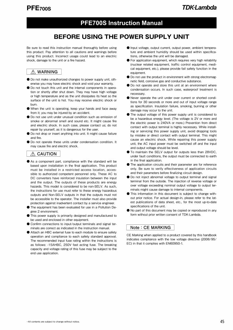
PFE700S
45・All contents are subject to change without notice.
PFE700S Instruction Manual
Be sure to read this instruction manual thoroughly before using this product. Pay attention to all cautions and warnings before using this product. Incorrect usage could lead to an electric shock, damage to the unit or a fire hazard.
WARNING
Do not make unauthorized changes to power supply unit, oth-erwise you may have electric shock and void your warranty.
Do not touch this unit and the internal components in opera-tion or shortly after shut down. They may have high voltage or high temperature and as the unit dissipates its heat so the surface of the unit is hot. You may receive electric shock or burn.
When the unit is operating, keep your hands and face away from it; you may be injured by an accident.
Do not use unit under unusual condition such as emission of smoke or abnormal smell and sound etc. It might cause fire and electric shock. In such case, please contact us; do not repair by yourself, as it is dangerous for the user.
Do not drop or insert anything into unit. It might cause failure and fire.
Do not operate these units under condensation condition. It may cause fire and electric shock.
CAUTION
As a component part, compliance with the standard will be based upon installation in the final application. This product must be installed in a restricted access location, acces-sible to authorized competent personnel only. These AC to DC converters have reinforced insulation between the input and the output. The outputs of these products are energy hazards. This model is considered to be non-SELV. As such, the instructions for use must refer to these energy hazardous outputs and Non-SELV outputs in that the outputs must not be accessible to the operator. The installer must also provide protection against inadvertent contact by a service engineer.
The equipment has been evaluated for use in a Pollution De-gree 2 environment.
This power supply is primarily designed and manufactured to be used and enclosed in other equipment.
Confirm connections to input/output terminals and signal ter-minals are correct as indicated in the instruction manual.
Attach an HBC external fuse to each module to ensure safety operation and compliance to each safety standard approval. The recommended input fuse rating within the instructions is as follows: -15AHBC, 250V fast acting fuse. The breaking capacity and voltage rating of this fuse may be subject to the end use application.
Input voltage, output current, output power, ambient tempera-ture and ambient humidity should be used within specifica-tions, otherwise the unit will be damaged.
For application equipment, which requires very high reliability (nuclear related equipment, traffic control equipment, medi-cal equipment, etc.), please provide fail safety function in the equipment.
Do not use the product in environment with strong electromag-netic field, corrosive gas and conductive substance.
Do not operate and store this unit at an environment where condensation occurs. In such case, waterproof treatment is necessary.
Never operate the unit under over current or shorted condi-tions for 30 seconds or more and out of input voltage range as specification. Insulation failure, smoking, burning or other damage may occur to the unit.
The output voltage of this power supply unit is considered to be a hazardous energy level. (The voltage is 2V or more and the electric power is 240VA or more.) Prevention from direct contact with output terminal is highly necessary. While install-ing or servicing this power supply unit, avoid dropping tools by mistake or direct contact with output terminal. This might cause an electric shock. While repairing this power supply unit, the AC input power must be switched off and the input and output voltage should be level.
To maintain the SELV output for outputs less than 28VDC, under fault conditions, the output must be connected to earth in the final application.
The application circuits and their parameter are for reference only. Be sure to verify effectiveness of application circuits and their parameters before finalizing circuit design.
Do not inject abnormal voltage to output terminal and signal terminal from the outside. The injection of reverse voltage or over voltage exceeding nominal output voltage to output ter-minals might cause damage to internal components.
This information in this document is subject to change with-out prior notice. For actual design-in, please refer to the lat-est publications of data sheet, etc., for the most up-to-date specifications of the unit.
No part of this document may be copied or reproduced in any form without prior written consent of TDK-Lambda.
Note:CE MARKING
CE Marking when applied to a product covered by this handbook indicates compliance with the low voltage directive (2006/95/EC) in that it complies with EN60950-1.
BEFORE USING THE POWER SUPPLY UNIT

PFE700S
46 ・All contents are subject to change without notice.
[Input side terminals]
AC(L): Input terminal live lineAC(N): Input terminal neutral line
+BC : +Boost voltage terminal-BC : -Boost voltage terminalR : External inrush current limiting resistor
[Output side terminals]
+V : +Output terminal-V : -Output terminal
+VM : +VOutput monitor terminal-VM : -VOutput monitor terminalNC : Make no external connectionENA : Power on signal terminal
1. Terminal Explanation
・ Baseplate can be connected to FG through M3 mounting tapped holes.・ Consider contact resistance when connecting AC(L), AC(N), R, +BC, -BC, +V, -V.・ Note that +BC and -BC terminals are primary voltage with high voltage (385VDC). Do not connect load from these terminals.・ Do not make external connection to NC terminal.
Fig. 1-1 Basic Connection
2. Explanations on Specifications
1 Input Voltage RangeInput voltage range is indicated below. Take care not to apply input voltage which is out of this specified range nor should a DC input voltage be applied as this would result into power module damage.
Input Voltage Range: Single Phase 85 to 265VACLine Frequency Range : 47 to 63Hz
AC(N) –V
+V
NC
ENA
–VM
–BC
+VM
+BCR
AC(L)
Name Plate
AC(N)
BASE-PLATE
TFR1
NC-VM
F1
Load
L=50mm
L1
C1C2
C3
C4
C5 C7
C6
C8
C9
C10
C11
C12
C13C14
C15 C16
AC(L)
R1
L2
-V
+V+VM
+BCR -BCENA
PFE700S
Imput Filter(For VCCI-classA)
This manual explains based on "Fig. 1-1 Basic Connection." Please do actual evaluation when changing circuit from Fig.1-1.

PFE700S
47・All contents are subject to change without notice.
F1: External Input FuseThis power module has no internal fuse. Use external fuse to acquire each safety standard and to further improve safety. Further, Fast-Blow type fuse must be used per one module. Also, in-rush surge current flows during line throw-in. Be sure to check I2t rating of external switch and exter-nal fuse.
Recommended External Fuse:15A
Select fuse based on rated voltage, rated current and surge current capability. (1)Voltage Ratings 100VAC line:AC125V 200VAC line:AC250V(2)Current Ratings Rated current is determined by the maximum input
current based on operating conditions and can be cal-culated by the following formula.
lin(max)=
Pout (Arms)(Formula 1-1)
Vin×Eff×PFIin(max):Maximum Input CurrentPout: Maximum Output PowerVin: Minimum Input VoltageEff: EfficiencyPF: Power Factor
For efficiency and power factor values, refer to sepa-rate document "PFE700S Series Evaluation Data".
C1, C4, C5:1μF(Film Capacitor)Ripple current flows through this capacitor. When selecting capacitor, be sure to check the allowable maximum ripple current rating of this capacitor. Verify the actual ripple current flowing through this capacitor by doing actual mea-surement.
Recommended Voltage Rating: 250VACNote)Connect C5 as near as possible towards the input termi-
nals of this power module.
L1, L2:6mHAdd common mode choke coil as EMI/EMS counter-mea-sure. When using multiple modules, connect coil to each module.Note)Depending on the input filter used, noise might increase
or power module might malfunction due to filter reso-nance.
C2, C3: 4,700pF(Ceramic Capacitor)Add ceramic capacitor as EMI/EMS countermeasure. Be sure to consider leakage current of your equipment when adding this capacitor.High withstand voltage are applied across this capacitor depending on the application. Select capacitors with high withstand voltage rating.
R1:470kΩConnect bleeder resistor across AC(L) and AC(N) termi-nals.
C6, C7: 1000pF(Ceramic Capacitor)Add ceramic capacitor as EMI/EMS countermeasure. Be sure to consider leakage current of your equipment when adding this capacitor.High withstand voltage are applied across this capacitor during withstand voltage test depending on the application. Select capacitors with high withstand voltage rating.Also, connect C6, C7 as close as possible to the termi-nals.
C8, C9:1μF(Film Capacitor)Ripple current flows through this capacitor. When selecting capacitor, be sure to check the allowable maximum ripple current rating of this capacitor. Verify the actual ripple current flowing through this capacitor by doing actual mea-surement.
Recommended Voltage Rating:450VDC
Note) Select Capacitor with more than 3A (rms) rating. Con-nect C8, C9 as near as possible towards the output ter-minals of this power module.
C10:780μF(390μF×2 pcs. in parallel) (Electrolytic Capacitor) Refer to "Selection Method of External Bulk Capacitor for Boost Voltage" below.Allowable external capacitance at nominal capacitor value is shown below.
Recommended Voltage Rating:450VDCRecommended Total Capacitor: 390uF to 1,200uF
Note)1. Do not connect capacitors with more than the above capacitance value as this would result into power module damage.
2. When using module below -20 deg C ambient temper-ature, AC ripple of boost voltage, output ripple voltage and start up characteristics might be affected by ESR characteristics of the bulk capacitors. Therefore, be sure to verify characteristics by actual evaluation.
C11: 1000pF(Ceramic Capacitor)Add ceramic capacitor as EMI/EMS countermeasure. High withstand voltage are applied across this capacitor during withstand voltage test depending on the application. Select capacitors with high withstand voltage rating.Also, connect C11 as close as possible to the terminals.
C12, C13:0.033μFConnect ceramic or film capacitor as EMI/EMS counter-measure and to reduce spike noise.Note)High voltage is applied across this capacitor during with-
stand voltage test depending on the application.Connect C12, C13 as near as possible towards the output terminals of this power module.
C14:220μFTo reduce output ripple noise voltage, connect electrolytic capacitors across +V and -V.Note)Connect C14 as near as possible to the +V and -V
output terminals of this power module.

PFE700S
48 ・All contents are subject to change without notice.
Recommended Voltage Rating:100VDC
C15:2.2μFConnect chip ceramic capacitor within 50mm from the out-put terminals +V and -V of the power module to reduce output spike noise. Also, note that output spike voltage may vary depending on the wiring pattern of the printed circuit board.
C16:220μFConnect C13 within 50mm from the output terminals +V and -V of the power module to stabilize operation.Note that the output ripple and line turn off characteristics of the power module might be affected by the ESR and ESL of the electrolytic capacitor.Also, note that output ripple voltage may vary depending on the wiring pattern of the printed circuit board. Sudden change in output voltage due to sudden load change or sudden input voltage change can be reduced by increasing external output capacitor value.
Recommended Voltage Rating:100VDCNote)1. Use low-impedance electrolytic capacitors with excel-
lent temperature characteristics. (Nichicon PM Series or equivalent)
2. For module operation at ambient temperature -20 deg C or less, output ripple voltage might be affected by ESR characteristics of the electrolytic capacitors. Increase the capacitor values shown below.
C14, C16: 100V 220μF x 2 parallel(Ambient Temperature<-20 deg C)
3. Take note of the maximum allowable ripple current of the electrolytic capacitor used. Especially, for sudden load current changes, verify actual ripple current and make sure that allowable maximum ripple current is not be exceeded.
Selection Method of External Bulk Capacitor for Boost Voltage
Boost voltage bulk capacitor is determined by boost volt-age ripple voltage, ripple current and hold-up time.Select capacitor value such that boost voltage ripple volt-age does not exceed 15Vp-p.Note) When ambient temperature is -20 deg C or less, Boost
voltage might increase due to ESR characteristics. Therefore, verify above characteristics by actual evalua-tion.
For output hold-up time, refer to separate document "PFE700S Series Evaluation Data" and use appropriate capacitor up to 1,200uF maximum. (It is recommended that verification should be done through actual evaluation).
For allowable ripple current value, refer to Fig.1-2 and se-lect a capacitor with higher ripple current rating.
0
500
1000
1500
2000
2500
0 20 40 60 80 100
100VAC
200VAC
Load Current (%)
Ripple Current (mA rms)
Fig. 1-2 Allowable ripple current value
TFR1:10 to 100 ohmBy connecting thermal fuse resistor across R and +BC terminals as shown in Fig.1-1, in-rush current during line throw-in can be suppressed. Failures due to in-rush current such as melting of external fuse, welding of relay or switch connecting joints or shutdown of No-Fuse Breakers (NFB) might occur. Therefore, be sure to connect this external thermal fuse resistor.Note that this module will not operate without this external resistor. Selection Method of External Resistor(1)Calculating Resistance Value for TFR1 Resistance can be calculated by the formula below.
R= Vin
(Ω)(Formula 1-2) lrush
R: Resistance Value for External TFR1Vin: Input Voltage converted to DC value = Input Voltage(rms)×√‾2Irush:Input surge current value
(2)Required Surge Current Rating Sufficient surge current withstand capability is re-
quired for external TFR1. Required surge current rat-ing can be selected by l2t. (Current squared multiplied by time)
l2t= Co×Vin2
(A2s)(Formula 1-3) 2×R
I2t: Current-squared multiplied by timeCo: Boost Voltage Bulk CapacitanceVin:Input Voltage converted to DC value = Input Voltage(rms)×√‾2R: Resistance Value for External TFR1
2 Maximum Ripple and NoiseThis value is measured according to the description below in accordance with JEITA-9131A (Section 7.12 and Sec-tion 7.13).In the basic connection shown in Fig.1-1, additional connection shown in Fig.2-1 is done for measurement. Capacitor (ceramic capacitor 2.2μF and electrolytic capacitor: 220μF) must be connected within 50mm from the output terminals. Then, connect coaxial cable with JEITA attachment across the ceramic capacitor electrodes. Use 100MHz bandwidth oscilloscope or equivalent. Also, note that output ripple voltage and output spike noise may vary depending on the wiring pattern of the printed circuit board. In general, output ripple voltage and output spike noise can be reduced by increasing external capacitor value.

PFE700S
49・All contents are subject to change without notice.
+
-
+V
Load
Wires must be as short as possible
50mm
JEITAAttachment R: 50Ω C: 4700pF
OscilloscopeR
C
1.5m 50ΩCoaxial Cable
-V
Fig. 2-1 Output Ripple Voltage (including Spike Noise) Measurement Method
3 Maximum Line RegulationMaximum line regulation is defined as the maximum output voltage change when input voltage is gradually changed (steady-state) within specification range.
4 Maximum Load RegulationMaximum load regulation is defined as the maximum out-put voltage change when output load current is gradually changed (steady-state) within specification range.When using power module in dynamic load mode, audible sound could be heard from the power module or large out-put voltage change can occur. Make prior evaluation thor-oughly before using this power module.
5 Over Current Protection (OCP)This module is equipped with OCP function. Output will automatically recover when short circuit or overload condition is removed. OCP value is fixed and can-not be adjusted externally.Note that continuous short circuit or overload condition might result in power module damage.
6 Over Voltage Protection (OVP)This module is equipped with OVP function. This value is set between 60.0V to 69.6V.When the OVP function activates, first cut off input line and verify that boost voltage has dropped down to 20V or less. Then, recover output by recycling input line. OVP value is fixed and cannot be set externally.
7 Over Temperature Protection (OTP)This module is equipped with OTP function. This func-tion will activate and shut down the output when ambient temperature or internal temperature abnormally rises. OTP activates at following baseplate temperature.
OTP operating temperature:105 to 130 deg C
When OTP function operates, output can be recovered by cooling down the baseplate sufficiently and letting the boost voltage drop down to 20V or less before recycling the input line.
8 Parallel Operation Current share parallel operation is possible for PFE700S Series by connecting the output terminal of each power module. Verify the allowable maximum total output current by actual evaluation such that maximum output current rat-ing of each module is not exceeded.Consult us for details when using PFE700S Series at par-allel operation.
9 Series OperationSeries operation is possible for PFE700S Series. Connections shown in Fig.9-1 and Fig.9-2 are possible.
+
-
+V
Load
-V
+V
-V
Fig. 9-1 Series Operation for High Output Voltage Applications
+
-
+VLoad
+
-Load
-V
+V
-V
Fig. 9-2 +/-Output Series Applications
10 Power ON Signal (ENA Terminal)This signal is located at the secondary side (output side) and is an open collector output.(Maximum sink current is 10mA and maximum applied volt-age is 75V.)When output voltage goes over 46V(TYP) at start up, Pow-er ON signal is "Low Level". On the other hand, output voltage threshold level for Power ON signal to turn "High Level" at shutdown varies accord-ing to output condition. Therefore, be sure to do actual verification.
11 Operating Ambient Temperature RangeThese products can be used in any orientation but be sure to consider enough airflow to avoid heat accumulation around the module. Consider surrounding components lay-out and set the PCB mounting direction such that air can flow through the heatsink by forced or convection cooling.This product can operate at actual mounting condition when baseplate temperature is maintained at or below the 100 deg C.Verify baseplate temperature at worst case operating con-dition at the measuring point shown in Fig.11-1.For Thermal Design details, refer to Application Notes "Thermal Design" section.

PFE700S
50 ・All contents are subject to change without notice.
Baseplate TemperatureMeasuring Point
Fig.11-1 Baseplate Measuring Point
Baseplate temperature range is limited according to Fig. 11-2.
-40 -20 0
0
20
40
60
80
100
20 40 60 8085
85
85
70
100Baseplate temperature ()
Load current (%)
80 100 120
0
20
40
60
80
100
140 160 180
Tbp:85Tbp:100
20085 265
220 240 260Input Voltage (VAC)
Load current (%)
Fig. 11-2 Derating Curve
To further improve the reliability, it is recommended to use this module with baseplate temperature derating.
12 Operating Ambient HumidityNote that dewdrop might cause power module abnormal operation or damage.
13 Storage Ambient TemperatureNote that rapid temperature change causes dewdrop caus-ing harmful effect on soldering condition of the terminal pins.
14 Storage Ambient HumidityStorage under high temperature and high humidity causes rust on terminal pins that causes deterioration of soldering conditions. Take enough caution when storing this module.
15 Cooling MethodFor details of thermal design, refer to Application Notes "Thermal Design" section.
16 Withstand VoltageThis module is designed to withstand applied voltage 2.5kVAC between input and baseplate, 3kVAC between input and output for a duration of 1 minute. When doing this test during incoming inspection, set the current limit of test equipment to 20mA. This module is designed to withstand applied voltage 1.5kVDC between output and baseplate for 1 minute. When doing this test during incoming inspection, be sure
to apply DC voltage only. Avoid applying AC voltage dur-ing this test because this will damage the module. Refrain from injecting high test voltage suddenly. Be sure to gradually increase the applied withstand voltage during testing and gradually reduce the voltage after the test.Especially, when using timer switch of the test equipment, impulse voltage which is higher than the applied set volt-age, is generated when the timer switch is cut off. This causes damage to the power module. Connect each termi-nal according to the circuit diagram shown below.For basic connection shown in Fig.1-1, do the same termi-nal connections.
Withstand Voltage TesterBASE-PLATE
AC(N)
AC(L)
R +BC -BC
+V
-V
+VMNCENA
-VM
PFE700S(Top View)
2.5kVAC 1 minute (20mA)Fig. 16-1 Input to Baseplate Withstand Voltage Test Method
BASE-PLATE
AC(N)
AC(L)
R +BC -BC
+V
-V
+VMNCENA
ーVM
PFE700S
Withstand Voltege Tester
(Top View)
3kVAC 1 minute (20mA)Fig.16-2 Input to Output Withstand Voltage Test Method
BASE-PLATE
AC(N)
AC(L)
R +BC -BC
+V
-V
+VMNCENA
-VM
PFE700S
Withstand Voltage Tester
(Top View)
1.5kVDC 1 minute Fig.16-3 Output to Baseplate Withstand Voltage Test Method

PFE700S
51・All contents are subject to change without notice.
Verify following items before concluding power module damage.
1)No output voltage Is specified input voltage applied? Is there no abnormality with the output load? Is the actual baseplate temperature within the speci-
fied operating temperature of this module?
2)Output voltage is low Is specified input voltage applied? Is there no abnormality with the output load?
3)Load regulation or line regulation is large Is specified input voltage applied? Are the input or output terminals firmly connected? Are the input and output wires too thin?
4)Large output ripple Is the measurement done according to methods
described Application Notes or is it an equivalent method?
3. Before Concluding Power Module Damage
17 Insulation ResistanceUse DC Insulation Resistance test equipment (MAX.500V) between output and baseplate.Insulation Resistance must be 100Mohm or more at 500VDC. Take caution that some types of test equipment generate high pulse voltage when switching applied volt-age. After test, discharge this module using resistor, etc.
BASE-PLATE
AC(N)
AC(L)
R +BC -BC
+V
-V
+VMNCENA
ーVM
PFE700S
Insulation Resistance Tester
(Top View)
100M ohm or more at 500VDCFig. 17-1 Insulation Resistance Test Method
18 Recommended Soldering ConditionRecommended soldering temperature is as follows.(1)Soldering Dip : 260, within 10 secondsPreheat : 130, within 60 seconds(2)Soldering iron : 350, within 3 seconds

52

・All specifications are subject to change without notice.
Precautions for Use
WARNING Do not modify, disassemble, or open this product. Failure to do so can cause electric shock hazard. TDK-Lambda cannot be held responsible for damage caused by modifications to this product.
Internal voltage can be retained inside the product. Do not touch any parts inside the product be-cause there can be high-voltage and high-temperature parts even when the electric current is not applied. This can cause an electric shock hazard or burn injury.
There can be high-voltage and high-temperature parts even in products without a cover. Do not touch them. Touching them can cause an electric shock hazard or burn injury.
While electric current is being applied, keep your hands and face away from it. This may cause in-jury or an unexpected accident.
CAUTION Be sure to read the catalogue and instruction manual before using this product. For strictly ac-curate information, request the specifications of the delivered product to check the information. Incorrect usage could lead to an electric shock, damage to the product or a fire hazard.
If there are differences between the specific information given for your product and this document, the specific information given for your product has priority.
Use this product within the specified input voltage, output power, output voltage, output current, and range of ambient temperature/ambient humidity. Using this product in conditions beyond the specification limits can shorten the lifetime of the product, or can cause, damage to the product, electric shock, or a fire hazard.
Also, measure the temperature inside the device to check that there are no problems. Check the direction the product should face and the conditions for ventilation in the specifications of the delivered product, and use the product in the correct manner.
Disconnect the power input before connecting inputs and outputs. If an internal fuse becomes burned out, do not use the unit by replacing the fuse. This can cause trouble inside the unit. Be sure to request us to repair the unit.
Insert fuses in the input circuit for products in which protection circuits (elements, fuses, etc.) are not installed, to prevent smoking or burning. Also for products with protection circuits installed inside, an appropriate use of protection circuits is recommended as there is possibility that the in-ternal protection circuit may not operate depending on the usage conditions.
Use only the fuses specified or recommended by TDK-Lambda for external fuses. This product is designed and manufactured as a component part to be installed in electronic de-vices. Attach the warning label to the unit and insert the notes in the instruction manual.
Malfunction and failure may be caused if this product is used in a strong electromagnetic field. Failure may be caused in the power supply unit due to corrosion if used in environments with corrosive gas (hydrogen sulfide, sulfur dioxide, etc.).
Malfunction and failure may be caused if this product is used in environments with conductive sub-stances or dust.
Be sure to take protective measures against the surge voltage caused by lightning, etc. Damage to the unit may be caused due to irregular voltage.
Connect the frame ground terminal of the power supply unit to the earth terminal of the device, for safety and to reduce noise. If grounding is not made, it may cause an electric shock hazard.
It is necessary to exchange consumable parts (built-in fan, electrolytic capacitor) periodically. Set an appropriate overhaul interval period for the performance of maintenance. There may be some cases where overhaul maintenance cannot be conducted due to unavailability of parts due to pro-duction discontinuation.
This product might fail accidentally or through unexpected conditions. When using this product with application devices, in which an extremely high reliability is required (Nuclear-related devices, traffic control devices, medical devices, etc.), be sure to ensure that the fail-safe function is effec-tive in the devices.
* As for EMI or immunity, they are measured in the TDK-Lambda standard conditions. It is not guar-anteed that this product meets industry standards or regulations when being used in different conditions of mounting and wiring. Assess and evaluate values on the actual device before use.
* To export this product, follow the necessary procedures of application for the export license by the government of Japan, etc., complying with the regulations of the Foreign Exchange and Foreign Trade Control Law.
* The information in this catalogue is subject to change without prior notice.
53