Embed Size (px)
Citation preview
Data code L6210057
V5.0
AC Drive | PLC | HMI | Servo Drive | Motor | MV Drive | New Energy
TUV Rheinland Group
ISO9001 Certified
Innova
tion
Advance+
NEVER STOP IMPROVING
Industrial Automation Integration
220V
CHARGE
L1
L2
L
L
B
B
B
CN3CN4
CN1CN2
Contact info of agency
Copyright Inovance. All Rights Reserved.©
Shenzhen lnovance Technology Co.,Ltd.Add.: Building E, Hongwei Industry Park, Liuxian Road, Baocheng No. 70 Zone, Bao’an District, ShenzhenTel: +86-755-2979 9595Fax: 86-755-2961 9897Service Hotline: 400-777-1260http://www.inovance.cn
Suzhou lnovance Technology Co.,Ltd.Add. No 16 Youxiang Rd, Yuexi Town, Wuzhong District,Suzhou 215104, P.R. ChinaTel 86-512-6637 6666Fax 86-512-6285 6720Service Hotline: 400-777-1260http //www inovance cn
+
: . ,
:+:+
: . .
Platform Advantages
Testing
With leading traction motor test bench
With Labs equipped with advanced testing equipment for EMC, IGBTs,
vibration and high/low temperature tests, and etc
With leading electric low/high-voltage test stations
Manufacturing
Flexible manufacturing
Reliable quality
Advanced manufacturing equipment
Fast delivery
Strict testing methods
EMC test
Vibration test bed
Walk-in high and low temperature humidity test chamber
About INOVANCE
NEVER STOP IMPROVING 01/02
As a leading industrial automation product and solution provider,
Inovance Technology (Stock code: 300124) is specialized in R&D,
manufacturing and sales of automation control products. Thanks to
a massive array of cutting-edge industrial automation control
technologies and fast delivery of customized solutions, we are able
to maximize value for both Inovance and our customers, mainly mid-
to-high-end equipment manufacturers.
Our products mainly include low-to-mid-voltage AC drives for
general and engineering purposes, high-voltage AC drives,
integrated and special drives, servo systems, PLCs, HMIs, PMSMs,
and new-energy vehicle controllers. We have now seized a
dominant share in the domestic mid-to-low-voltage AC drive market
and also pioneered in developing integrated and special products
for various sectors.
As a national high-tech company, we have 213 patents by December
31, 2013, including 16 invention, 154 utility model, 43 design
patents in addition to 80 software copyrights. Besides, we have mastered a series of core platform technologies such as high-
performance vector converter, PLC, servo, and PMSM technologies. Moreover, we have set up a R&D team with numerous R&D
professionals experienced in R&D of core platform technologies, applied technologies and products. Inovance released the IPO
on the GEM Board of the Shenzhen Stock Exchange in September 2010.
Inovance Suzhou Factory (Phase-2)
Large R&D investmentR&D team: around 500 engineers;Invest 10% of previous year’s sales revenue on R&D.
IGBT test platformSimulation analysis of different limit working conditions (stray inductance, temperature simulation) of IGBT;Pre-research analysis of high volume drives.
Strong-electricity finite element analysis platformTopology simulation analysis;Busbar current simulation analysis.
Simulation analysis of drive algorithm and heat designAlgorithm simulation, comparison and verification;Thermal simulation analysis for structure design.
Vibration test platformSimulation of various vibration tests
R&D
Full-automatic SMT line Traction motor test bench
India
Italy
Japan
Malaysia
Thailand
Turkey
Zimbabwe
South Africa
Spain
Poland
Netherlands
Brazil
Philippines
Indonesia
UAE
Egypt
Bosnia and Herzegovina
Russia
Canada
Taiwan
Changchun Huitong Optoelectronic Co., Ltd. (Weton)
Nanjing Inovance Industrial Vision Technology Co., Ltd.
Hangzhou Huikun Control Technology Co., Ltd.
Shenzhen Inovance Technology Co., Ltd.
European Technical Center Inova Automation Italy srl
Inova Automation Pvt., Ltd.
Inova Automation Co., Limited
Jiangsu Huicheng Motor Co., Ltd.
Beijing Inovance Technology Co., Ltd.
Suzhou Inovance Technology Co., Ltd.
Ningbo EST Technology Co., Ltd.
Korea
Vietnam
Hong Kong
Overseas branch
Overseas distributor
Overseas distributor in plan
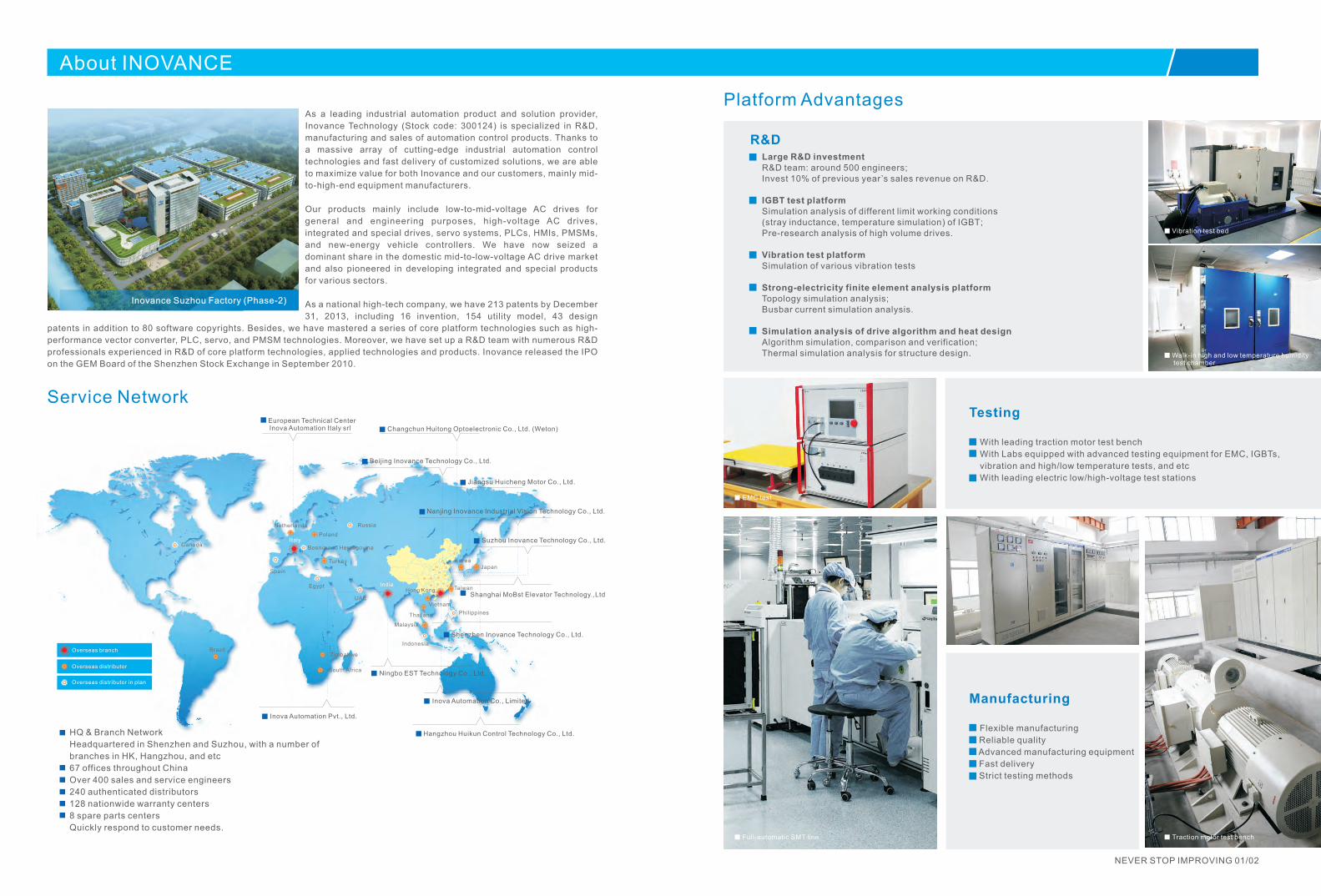
Service Network
HQ & Branch Network
Headquartered in Shenzhen and Suzhou, with a number of
branches in HK, Hangzhou, and etc
67 offices throughout China
Over 400 sales and service engineers
240 authenticated distributors
128 nationwide warranty centers
8 spare parts centers
Quickly respond to customer needs.
Shanghai MoBst Elevator Technology.,Ltd
Our Strengths
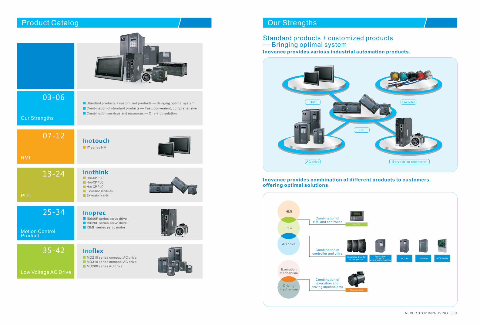
Standard products + customized products — Bringing optimal systemInovance provides various industrial automation products.
HMI
PLC
Servo drive and motor AC drive
Encoder
Inovance provides combination of different products to customers, offering optimal solutions.
HMI
PLC
Combination of HMI and controller
H0U-XP
AC drive
Execution mechanism
Driving mechanism Torque motor
Integrated drive for air compressor
Product Catalog
Our Strengths
Standard products + customized products — Bringing optimal system
Combination of standard products — Fast, convenient, comprehensive
Combination services and resources — One-stop solution
HMI
PLC
Motion Control Product
Low Voltage AC Drive
IT series HMI
H2U-XP PLC
H1U-XP PLC
H0U-XP PLC
Extension modules
Extension cards
IS600P series servo drive
IS620P series servo drive
ISMH series servo motor
MD210 series compact AC drive
MD310 series compact AC drive
MD280 series AC drive
NEVER STOP IMPROVING 03/04
03-06
07-12
13-24
25-34
35-42NICE seriesCAN600MD330
Specialized drive for
wire drawing machine
Combination of controller and drive
Combination of execution and
driving mechanisms
Our Strengths
Combination of standard products — Fast, convenient, comprehensive『Fast』
CAN
link CANlink
HMI
Software
PLC software Autoshop
Servo drive software
HMI software Editor
Automatic control
AC drive
MotioncontrolM
odbus
RT
U
Modbus R
TU
Modbus R
TU
Rapid and efficient connection between Inovance products can be realized through CANlink bus communication.
『Convenient』
Parameters of the AC drive or servo drive in the system can be modified by simply plugging in a U disk into the HMI.
HMI
PLC
AC drive Servo drive
HMI
PLC
『Comprehensive』
Modbus
POWERLINKETHE NET
P R O F I
B U SPROCESS FIELD BUS
E heronformance testedC
Inovance products support most mainstream communication protocols and thus are able to communication with other products.
CANlinkCANlink
Note: Part of the above communication networking is under development.
Combination services and resources One-stop solution—
Usertechnical
call center
One-stop solution
『Service Integration』
Inovance has set up a technical call center and a team of single-product service engineers to offer one-stop solutions for users.
『Resource Integration』
+ ++
PLC software Autoshop HMI software EditorServo drive software IS-OperaAC drive software Insight
InoSYS is a powerful monitoring software that combines Inovance Autoshop, Insight, IS-Opera and Editor together, which is convenient and easy to use.
AC drive
PLC
HMI
Servo drive and servo motor
Comprehensive Background SoftwareLogin Interface
Ino-auto Comprehensive Background Software
NEVER STOP IMPROVING 05/06
Programs of the PLC/HMI or parameters of the AC drive or servo drive in the system can be modified by sampling adding a downloading cable to the PC.
AC drive Servo drive

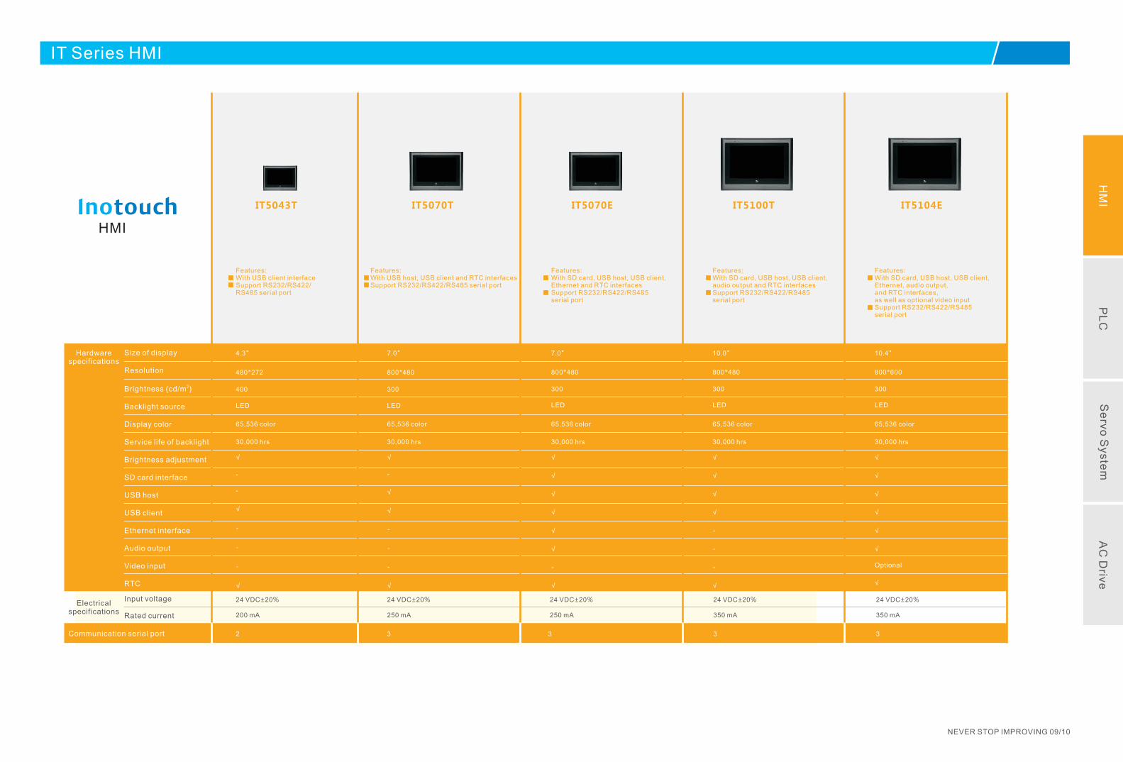
IT Series HMI
IT Series HMI
NEVER STOP IMPROVING 07/08
Hardware specifications
HMI
Electrical specifications
Communication serial port
Input voltage
Rated current
Size of display
Resolution
2Brightness (cd/m )
Backlight source
Display color
Service life of backlight
Brightness adjustment
SD card interface
USB host
USB client
Ethernet interface
Audio output
Video input
RTC
Features:With USB client interfaceSupport RS232/RS422/RS485 serial port
24 VDC±20%
200 mA
2
IT5043T
4.3"
480*272
400
LED
Features:With USB host, USB client and RTC interfacesSupport RS232/RS422/RS485 serial port
3
IT5070T
7.0"
800*480
300
LED
24 VDC±20%
250 mA
Features:With SD card, USB host, USB client,Ethernet and RTC interfacesSupport RS232/RS422/RS485serial port
3
IT5070E
7.0"
800*480
300
LED
24 VDC±20%
250 mA
Features:With SD card, USB host, USB client,audio output and RTC interfacesSupport RS232/RS422/RS485 serial port
3
IT5100T
10.0"
800*480
300
LED
24 VDC±20%
350 mA
Features:With SD card, USB host, USB client, Ethernet, audio output, and RTC interfaces, as well as optional video input Support RS232/RS422/RS485 serial port
IT5104E
10.4"
800*600
300
LED
24 VDC±20%
350 mA
3
IT Series HMI
NEVER STOP IMPROVING 09/10
HM
IP
LC
Se
rvo S
yste
mA
C D
rive
65,536 color
30,000 hrs
√
-
-
√
-
-
-
√
√
-
√
√
-
-
-
√
65,536 color
30,000 hrs
√
√
√
√
√
√
-
√
√
√
√
√
-
-
-
√
√
√
√
√
√
√
Optional
√
65,536 color
30,000 hrs
65,536 color
30,000 hrs
65,536 color
30,000 hrs
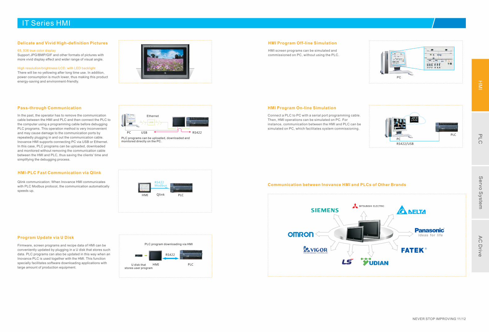
HMI Program Off-line Simulation
HMI screen programs can be simulated and
commissioned on PC, without using the PLC.
PC
Program Update via U Disk
Firmware, screen programs and recipe data of HMI can be
conveniently updated by plugging in a U disk that stores such
data. PLC programs can also be updated in this way when an
Inovance PLC is used together with the HMI. This function
specially facilitates software downloading applications with
large amount of production equipment.U disk that
stores user program
PLC program downloading via HMI
PLCHMI
RS422
HMI Program On-line Simulation
Connect a PLC to PC with a serial port programming cable.
Then, HMI operations can be simulated on PC. For
instance, communication between the HMI and PLC can be
simulated on PC, which facilitates system commissioning.
PC
RS422/USB
PLC
Pass-through Communication
In the past, the operator has to remove the communication
cable between the HMI and PLC and then connect the PLC to
the computer using a programming cable before debugging
PLC programs. This operation method is very inconvenient
and may cause damage to the communication ports by
repeatedly plugging in and out the communication cable.
Inovance HMI supports connecting PC via USB or Ethernet.
In this case, PLC programs can be uploaded, downloaded
and monitored without removing the communication cable
between the HMI and PLC, thus saving the clients’ time and
simplifying the debugging process.
LAN
PC USB
Ethernet
PLC programs can be uploaded, downloaded and monitored directly on the PC.
RS422
Delicate and Vivid High-definition Pictures
65, 536 true color display
High resolution/brightness LCD, with LED backlight
Support JPG/BMP/GIF and other formats of pictures with
more vivid display effect and wider range of visual angle.
There will be no yellowing after long time use. In addition,
power consumption is much lower, thus making this product
energy-saving and environment-friendly.
HMI-PLC Fast Communication via Qlink
Qlink communication: When Inovance HMI communicates
with PLC Modbus protocol, the communication automatically
speeds up.
HMI PLC
Modbus
Qlink
RS422Communication between Inovance HMI and PLCs of Other Brands
MITSUBISHI ELECTRIC
ideas for life
NEVER STOP IMPROVING 11/12
IT Series HMI
HM
IP
LC
Se
rvo S
yste
mA
C D
rive

H2U/1U Series PLC/0U-XP
H2U/1U Series PLC/0U-XP
NEVER STOP IMPROVING 13/14
Points of main module
High speed input
High speed output
Communicationprotocols
Technical specifications
PLC
Extensibility
Communication ports
Options
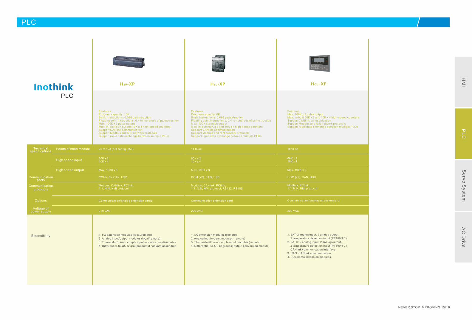
Features:Program capacity: 16KBasic instructions: 0.098 μs/instructionFloating point instructions: 0.4 to hundreds of μs/instructionMax. 100K x 3 pulse outputMax. in-built 60K x 2 and 10K x 4 high-speed countersSupport CANlink communicationSupport Modbus and N:N network protocolsSupport rapid data exchange between multiple PLCs
H2U-XP
20 to 128 (full config. 256)
220 VAC
60K x 210K x 4
Max. 100K x 3
Modbus, CANlink, PClink, 1:1, N:N, HMI protocol
1. I/O extension modules (local/remote)
2. Analog input/output modules (local/remote)
3. Thermistor/thermocouple input modules (local/remote)
4. Differential-to-OC (2 groups) output conversion module
COM (x3), CAN, USB
Communication/analog extension cards
PLC
NEVER STOP IMPROVING 15/16
Voltage of power supply
H1U-XP
14 to 60
Modbus, CANlink, PClink, 1:1, N:N, HMI protocol, RS422, RS485
1. I/O extension modules (remote)
2. Analog input/output modules (remote)
3. Thermistor/thermocouple input modules (remote)
4. Differential-to-OC (2 groups) output conversion module
Features:Program capacity: 8KBasic instructions: 0.098 μs/instructionFloating point instructions: 0.4 to hundreds of μs/instructionMax. 100K x 3 pulse outputMax. in-built 60K x 2 and 10K x 4 high-speed countersSupport CANlink communicationSupport Modbus and N:N network protocolsSupport rapid data exchange between multiple PLCs
60K x 210K x 4
Max. 100K x 3
COM (x2), CAN, USB
Communication extension card
220 VAC
HOU-XP
16 to 32
60K x 210K x 4
Modbus, PClink, 1:1, N:N, HMI protocol
1. 6AT: 2 analog input, 2 analog output,
2 temperature detection input (PT100/TC)
2. 6ATC: 2 analog input, 2 analog output,
2 temperature detection input (PT100/TC),
CANlink communication interface
3. CAN: CANlink communication
4. I/O remote extension modules
Features:Max. 100K x 2 pulse outputMax. in-built 60K x 2 and 10K x 4 high-speed countersSupport CANlink communicationSupport Modbus and N:N network protocolsSupport rapid data exchange between multiple PLCs
Max. 100K x 2
COM (x2), CAN, USB
Communication/analog extension card
220 VAC
HM
IP
LC
Se
rvo S
yste
mA
C D
rive
H2U-XP Series PLC
Features of H2U-XP Series PLC
Provide multi-channel high frequency/speed I/O ports, and various motion and positioning control functions;
Provide 3 separate communication ports (extensible to 4); provide various communication protocols and instructions,
which facilitates system integration;
Provide sub-program encryption and protection to user program uploading to protect user’s property rights.
Provide large program memory with up to 16k steps; automatically save memory data upon power failure;
Support up to 128 sub-programs and 21 interrupt sub-programs, with fast computing speed;
Integrate large capacity power which can provide power directly to sensors, HMI and external auxiliary relays.
Models of H2U-XP Series PLC
H2U-3232MR/T-XP
H2U-3624MR/T-XP
H2U-6464MR/T-XPH2U-4040MR/T-XP
H2U-1616MR/T-XP
H2U-2416MR/T-XP
H2U-1010MR/T-XP
Technical Specifications of H2U-XP Series PLC
NEVER STOP IMPROVING 17/18
I/O: 24 inputs 16 outputs, 40-point relay output (60K x2/10K x4 high speed inputs)H2U-2416MR-XP
I/O: 24 inputs 16 outputs, 40-point transistor output (60K x2/10K x4 high speed inputs; 100K x2 high speed outputs)H2U-2416MT-XP
I/O: 36 inputs 24 outputs, 60-point relay output (60K x2/10K x4 high speed inputs)H2U-3624MR-XP
I/O: 36 inputs 24 outputs, 60-point transistor output (60K x2/10K x4 high speed inputs; 100K x2 high speed outputs)H2U-3624MT-XP
I/O: 32 inputs 32 outputs, 64-point relay output (60K x6 high speed inputs)H2U-3232MR-XP
I/O: 32 inputs 32 outputs, 64-point transistor output (60K x6 high speed inputs; 100K x3 high speed outputs)H2U-3232MT-XP
I/O: 40 inputs 40 outputs, 80-point relay output (60K x6 high speed inputs)H2U-4040MR-XP
I/O: 40 inputs 40 outputs, 80-point transistor output high speed inputs; high speed outputs) (60K x6 100K x3 H2U-4040MT-XP
I/O: 64 inputs 64 outputs, 128-point relay output (60K x6 high speed inputs)H2U-6464MR-XP
I/O: 64 inputs 64 outputs, 128-point transistor output (60K x6 high speed inputs; 100K x3 high speed outputs)H2U-6464MT-XP
I/O: 10 inputs 10 outputs, 20-point relay output (60K x2/10Kx4 high speed inputs)H2U-1010MR-XP
I/O: 60K /10K high speed inputs; 100K high speed outputs)10 inputs 10 outputs, 20-point transistor output ( x2 x4 x3H2U-1010MT-XP
I/O: 16 inputs 16 outputs, 32-point relay output x6 high speed inputs) (60K H2U-1616MR-XP
I/O: 16 inputs 16 outputs, 32-point transistor output (60K x6 high speed inputs; 100K x3 high speed outputs)H2U-1616MT-XP
DescriptionModel
I/O: 32 inputs 32 outputs, 64-point transistor output (100K x6 high speed inputs; 100K x5 high speed outputs)H2U-3232MTQ
I/O: 32 inputs 32 outputs, 64-point transistor output (100K x8 high speed outputs)H2U-3232MTP
I/O: 40 inputs 40 outputs, 80-point relay output (100K x8 AB-phase high speed outputs)H2U-4040MR-8AB
I/O: 16 inputs 16 outputs, 32-point transistor output (dedicated for hydropower industry)H2U-1616MTS
Specialized controller configured with analog I/O: 8DI, 10DO, 9AI, 1IO, SCIx4H2U-8A91G-XP
Circular scanning, interrupt commands
Batch processing (when executing END instruction); instant refresh I/O
Step ladder, instruction list and SFC
27 sequence instructions, 2 step ladder instructions
0.098 μs/instruction
0.4 to hundreds of μs/instruction
X000 to X377 (octal): 256 points
16K steps (including notes file register)
Y000 to Y377 (octal): 256 points
Octal: 256 points
SFC & STL
Applied instruction
Basic instruction
Applied instruction
Total input points (with extension)
Total output points (with extension)
Total I/O points (with extension)
General use ※1
Retentive use ※2
Retentive use ※3
Special use
Initialization
General use ※1
Retentive use ※2
Signal use ※2
100 ms
10 ms
1 ms accumulative ※3
100 ms accumulative ※3
16-bit single direction ※1
16 ※2-bit single direction
32 ※1-bit dual-direction
Operation control mode
I/O control mode
Programming language
Max. memory capacity
Type of instructions
I/O points
Auxiliary relay
Status register
Timer (time limit)
32 ※2-bit dual-direction
32
※2
-bit high speed
dual-direction
16 ※1-bit (general use)
16 ※2-bit (retentive use)
16 ※3-bit (retentive use)
Counter
D
(two registers: 32 bit)
ata register
16-bit (special use)
16-bit (indexed addressing)
CALL and CJ jump
PointerInput interrupt
Counting interrupt
Timing interrupt
Main controlNesting
Decimal (K)
Hexadecimal (H)Constant
Item
298 instructions
Processing speed
M0 to M499: 500 points
M500 M1023: to 524 points
M1024 M3071: to 2048 points
M8000 M8511: to 512 points
T0 to T199: 200 points (0.1 to 3,276.7s)
T246 to T249: 4 points (0.001 to 32.767s)
T250 to T255: 6 points (0.1 to 3276.7s)
C0 to C99: 100 points (0 to 32767 counting)
C100 to C199: 100 points (0 to 32767 counting)
T200 to T245: 46 points (0.01 to 327.67s)
C200 to C219: 20 points (-2147483648 to +2147483647 counting)
C220 to C234: 15 points (-2147483648 to +2147483647 counting)
C235 to 21 points (-2147483648 to +2147483647C255: counting)
D0 to D199: 200 points
D200 to D511: 312 points
D512 to D7999: 7488 points(File register can be set at a unit of500 points after D1000.)
D8000 D8511: to 512 points
V0 to V7, Z0 to Z7: 16 points
P0 to P127: 128 points
I00X I50X: to 6 points
I010 to I060: 6 points
I6XX I8XX: to 3 points
N0 to N7: 8 points
16 bit: -32,768 +32,767;
to
32 bit: -2,147,483,648 to +2,147,483,647
16 bit: 0 to FFFF; 32 bit: 0 to FFFFFFFF
※1 Non-battery storage area: can be set as “Battery storage area”.
※2 Battery storage area: can be set as “Non-battery storage area”.
※3 Fixed battery storage area: storage feature cannot be changed.
H2U-XP
HM
IP
LC
Se
rvo S
yste
mA
C D
rive
S0 to S9
S10 to S499
S500 to S899
S900 to S999
H1U-3624MR/T-XPH1U-2416MR/T-XPH1U-1614MR/T-XPH1U-1410MR/T-XPH1U-0806MR/T-XP
NEVER STOP IMPROVING 19/20
Description
I/O: 14 inputs 10 outputs, 24-point relay output (60K x2/10K x4 high speed inputs)H1U-1410MR-XP
I/O: 14 inputs 10 outputs, 24-point transistor output (60K x2/10K x4 high speed inputs; 100K x3 high speed outputs)H1U-1410MT-XP
I/O: 16 inputs 14 outputs, 30-point relay output (60K x2/10K x4 high speed inputs)H1U-1614MR-XP
I/O: 16 inputs 14 outputs, 30-point transistor output (60K x2/10K x4 high speed inputs; 100K x3 high speed outputs)H1U-1614MT-XP
I/O: 24 inputs 16 outputs, 40-point relay output (60K x2/10K x4 high speed inputs)H1U-2416MR-XP
I/O: 24 inputs 16 outputs, 40-point transistor output (60K x2/10K x4 high speed inputs; 100K x3 high speed outputs)H1U-2416MT-XP
I/O: 28 inputs 20 outputs, 48-point relay output (60K x2/10K x4 high speed inputs)H1U-2820MR-XP
I/O: 28 inputs 20 outputs, 48-point transistor output high speed inputs; high speed outputs) (60K x2/10K x4 100K x3 H1U-2820MT-XP
I/O: 36 inputs 24 outputs, 60-point relay output (60K x2/10K x4 high speed inputs)H1U-3624MR-XP
I/O: 36 inputs 24 outputs, 60-point transistor output (60K x2/10K x4 high speed inputs; 100K x3 high speed inputs)H1U-3624MT-XP
I/O: 8 inputs 6 outputs, 14-point relay output (60K x2/10K x4 high speed inputs)H1U-0806MR-XP
I/O: 8 inputs 6 outputs, 14-point transistor output high speed inputs; high speed outputs) (60K x2/10K x4 100K x3 H1U-0806MT-XP
I/O: 12 inputs 8 outputs, 20-point relay output high speed inputs) (60K x2/10K x4 H1U-1208MR-XP
I/O: 12 inputs 8 outputs, 20-point transistor output (60K x2/10K x4 high speed inputs; 100K x3 high speed outputs)H1U-1208MT-XP
Model
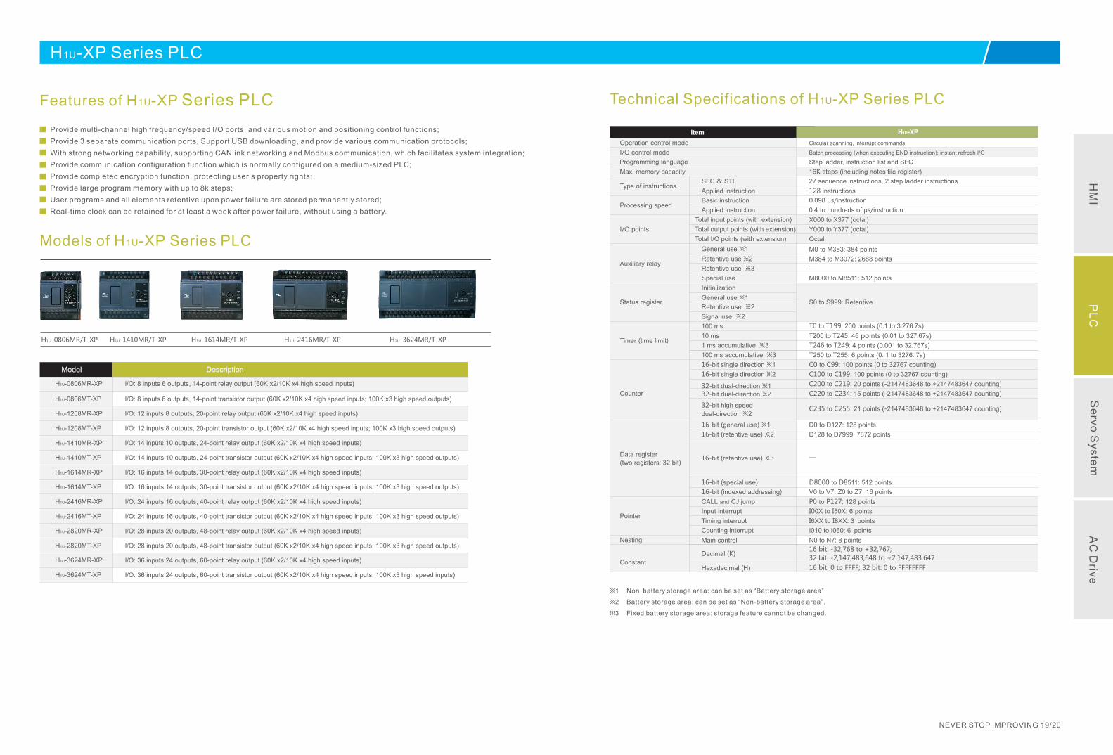
Technical Specifications of H1U-XP Series PLC
Circular scanning, interrupt commands
Batch processing (when executing END instruction); instant refresh I/O
Step ladder, instruction list and SFC
27 sequence instructions, 2 step ladder instructions
128 instructions
0.098 μs/instruction
0.4 to hundreds of μs/instruction
X000 to X377 (octal)
16K steps (including notes file register)
Y000 to Y377 (octal)
Octal
SFC & STL
Applied instruction
Basic instruction
Applied instruction
Total input points (with extension)
Total output points (with extension)
Total I/O points (with extension)
General use ※1
Retentive use ※2
Retentive use ※3
Special use
Initialization
General use ※1
Retentive use ※2
Signal use ※2
100 ms
10 ms
1 ms accumulative ※3
100 ms accumulative ※3
16-bit single direction ※1
16 ※2-bit single direction
32 ※1-bit dual-direction
Operation control mode
I/O control mode
Programming language
Max. memory capacity
Type of instructions
I/O points
Auxiliary relay
Status register
Timer (time limit)
32 ※2-bit dual-direction
32
※2
-bit high speed
dual-direction
16 ※1-bit (general use)
16 ※2-bit (retentive use)
16 ※3-bit (retentive use)
Counter
D
(two registers: 32 bit)
ata register
16-bit (special use)
16-bit (indexed addressing)
CALL and CJ jump
PointerInput interrupt
Counting interrupt
Timing interrupt
Main controlNesting
Decimal (K)
Hexadecimal (H)Constant
Item
Processing speed
M0 to M383: 384 points
M384 to M3072: 2688 points
—
M8000 to M8511: 512 points
T0 to T199: 200 points (0.1 to 3,276.7s)
T246 to T249: 4 points (0.001 to 32.767s)
T250 to T255: 6 points (0.1 to 3276.7s)
C0 to C99: 100 points (0 to 32767 counting)
C100 to C199: 100 points (0 to 32767 counting)
T200 to T245: 46 points (0.01 to 327.67s)
C200 to C219: 20 points (-2147483648 to +2147483647 counting)
C220 to C234: 15 points (-2147483648 to +2147483647 counting)
C235 to 21 points (-2147483648 to +2147483647C255: counting)
D0 to D127: 128 points
D128 to D7999: 7872 points
—
D8000 to D8511: 512 points
V0 to V7, Z0 to Z7: 16 points
P0 to P127: 128 points
I00X I50X: to 6 points
I010 to I060: 6 points
I6XX I8XX: to 3 points
N0 to N7: 8 points
16 bit: -32,768 +32,767;
to
32 bit: -2,147,483,648 to +2,147,483,647
16 bit: 0 to FFFF; 32 bit: 0 to FFFFFFFF
※1 Non-battery storage area: can be set as “Battery storage area”.
※2 Battery storage area: can be set as “Non-battery storage area”.
※3 Fixed battery storage area: storage feature cannot be changed.
S0 to S999: Retentive
H1U-XP
Models of H1U-XP Series PLC
Features of H1U-XP Series PLC
H1U-XP Series PLC
Provide multi-channel high frequency/speed I/O ports, and various motion and positioning control functions;
Provide 3 separate communication ports, Support USB downloading, and provide various communication protocols;
With strong networking capability, supporting CANlink networking and Modbus communication, which facilitates system integration;
Provide communication configuration function which is normally configured on a medium-sized PLC;
Provide completed encryption function, protecting user’s property rights;
Provide large program memory with up to 8k steps;
User programs and all elements retentive upon power failure are stored permanently stored;
Real-time clock can be retained for at least a week after power failure, without using a battery.
HM
IP
LC
Se
rvo S
yste
mA
C D
rive
H0U-XP Series PLC
H0U-0808MR-XP
Attributes
of
Display
Memory
Display area
LCD type
Backlight
Displayed language
External size
Size of display
Weight
Power supply
Flash
SpecificationsModel
192*64
Yellow green background,
dark blue text
Yellow green LED backlight
Chinese, English
130*65 mm
104*39 mm
105 g
3.3 V
56 K
Operation control mode
Programming language
Processing speed
Retentive upon power
failure
User program capacity
I/O points
High-speed processing
Communication
SpecificationsItem
Circular scanning
Step ladder, instruction list and SFC
0.26 ns (basic instructions)
Flash ROM retentive
8K steps
8 inputs 8 outputs, 16 inputs 16 outputs
High-speed counter x 2, pulse output x 2
RS485, USB
『Text Specifications』 『PLC Specifications』
Extension Modules of H2U/H1U-XP Series PLC
NEVER STOP IMPROVING 21/22
H2U-2ADH2U-4ADH2U-4ADR
H2U-2DAH2U-4DAH2U-4DAR
H2U-4AMH2U-6AMH2U-6CM
H2U-4PT-XPH2U-4PTR-XPH2U-4TC-XPH2U-4TCR-XP
H2U-1600ENNH2U-1600ENDRH2U-0800ENDR
H2U-0016ERNH2U-0016ERDRH2U-0016ETNH2U-0016ETDRH2U-0008ERNH2U-0008ETN
H2U-0404ERNH2U-0404ETNH2U-0808ERNH2U-0808ERDRH2U-0808ETNH2U-0808ETDR
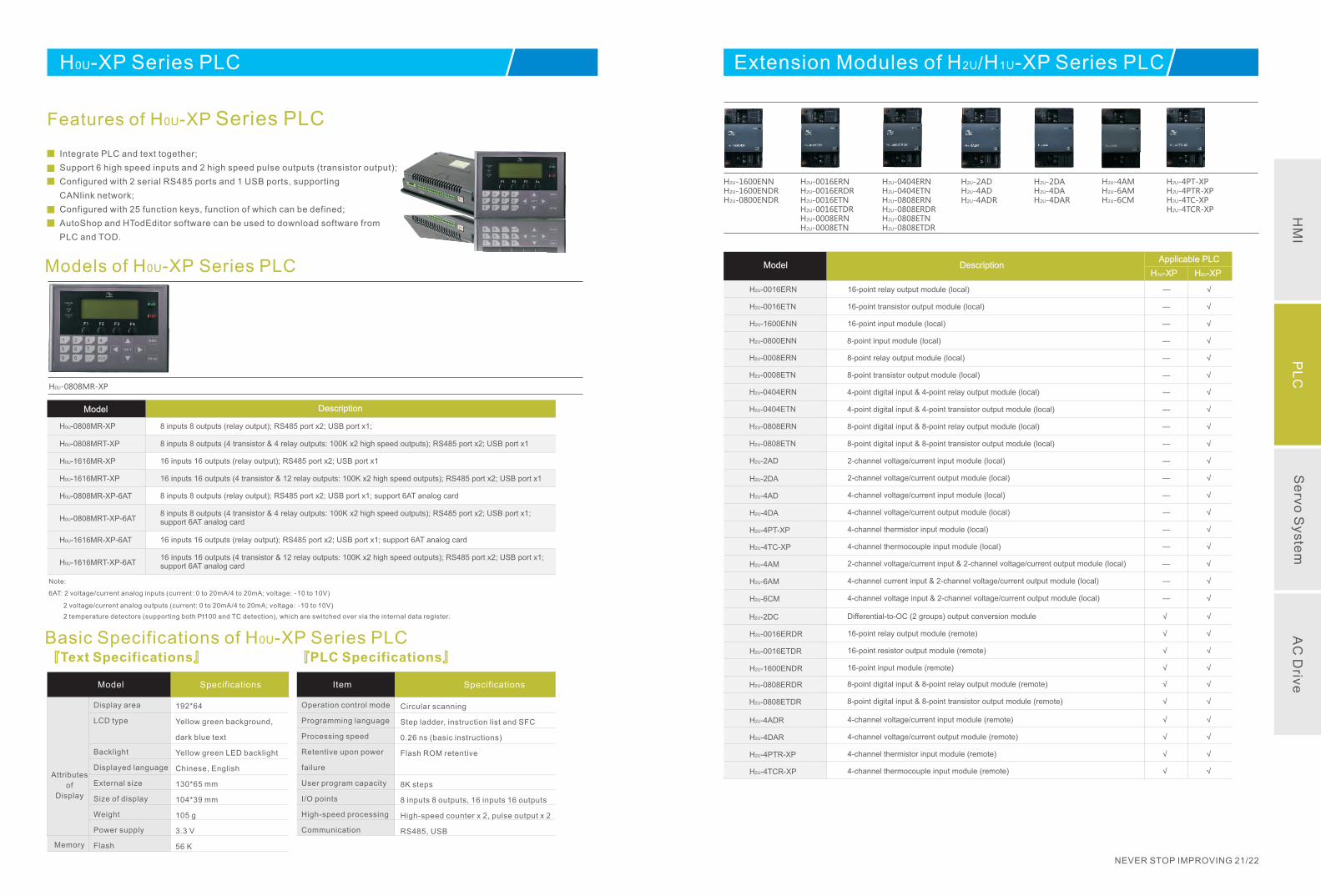
Features of H0U-XP Series PLC
Integrate PLC and text together;
Support 6 high speed inputs and 2 high speed pulse outputs (transistor output);
Configured with 2 serial RS485 ports and 1 USB ports, supporting
CANlink network;
Configured with 25 function keys, function of which can be defined;
AutoShop and HTodEditor software can be used to download software from
PLC and TOD.
Models of H0U-XP Series PLC
8 inputs 8 outputs (relay output); RS485 port x2; USB port x1; support 6AT analog cardH0U-0808MR-XP-6AT
8 inputs 8 outputs (4 transistor & 4 relay outputs: 100K x2 high speed outputs); RS485 port x2; USB port x1; support 6AT analog card H0U-0808MRT-XP-6AT
16 inputs 16 outputs (relay output); RS485 port x2; USB port x1; support 6AT analog cardH0U-1616MR-XP-6AT
16 inputs 16 outputs (4 transistor & 12 relay outputs: 100K x2 high speed outputs); RS485 port x2; USB port x1; support 6AT analog card H0U-1616MRT-XP-6AT
8 inputs 8 outputs (relay output); RS485 port x2; USB port x1; H0U-0808MR-XP
8 inputs 8 outputs (4 transistor & 4 relay outputs: 100K x2 high speed outputs); RS485 port x2; USB port x1H0U-0808MRT-XP
16 inputs 16 outputs (relay output); RS485 port x2; USB port x1H0U-1616MR-XP
16 inputs 16 outputs (4 transistor & 12 relay outputs: 100K x2 high speed outputs); RS485 port x2; USB port x1 H0U-1616MRT-XP
DescriptionModel
Note:
6AT: 2 voltage/current analog inputs (current: 0 to 20mA/4 to 20mA; voltage: -10 to 10V)
2 voltage/current analog outputs (current: 0 to 20mA/4 to 20mA; voltage: -10 to 10V)
2 temperature detectors (supporting both Pt100 and TC detection), which are switched over via the internal data register.
Basic Specifications of H0U-XP Series PLC
DescriptionModelApplicable PLC
H1U-XP H2U-XP
16-point relay output module (local)H2U-0016ERN — √
16-point transistor output module (local) H2U-0016ETN — √
16 input module (local)-point H2U-1600ENN — √
Differential-to-OC (2 groups) output conversion moduleH2U-2DC
2-channel voltage/current output module (local)H2U-2DA — √
4-channel voltage/current input module (local)H2U-4AD — √
4-channel voltage/current output module (local)H2U-4DA — √
4-channel thermistor input module (local)H2U-4PT-XP — √
4-channel thermocouple input module (local)H2U-4TC-XP — √
2-channel voltage/current input module (local)H2U-2AD — √
2-channel voltage/current input & 2-channel voltage/current output module (local)H2U-4AM — √
4-channel current input & 2-channel voltage/current output module (local)H2U-6AM — √
4-channel voltage input & 2-channel voltage/current output module (local)H2U-6CM — √
4-channel voltage/current input module (remote)H2U-4ADR √ √
4-channel voltage/current output module (remote)H2U-4DAR √ √
4-channel thermistor input module (remote)H2U-4PTR-XP √ √
4-channel thermocouple input module (remote) H2U-4TCR-XP √ √
8-point input module (local)H2U-0800ENN — √
8-point relay output module (local) H2U-0008ERN — √
8-point transistor output module (local) H2U-0008ETN — √
4 digital input & 4 point relay output module (local) -point -H2U-0404ERN — √
4-point digital input & 4-point transistor output module (local) H2U-0404ETN — √
8-point digital input & 8-point relay output module (local) H2U-0808ERN — √
8-point digital input & 8-point transistor output module (local) H2U-0808ETN — √
8-point digital input & 8-point relay output module (remote)H2U-0808ERDR √ √
8-point digital input & 8-point transistor output module (remote)H2U-0808ETDR √ √
16-point relay output module (remote)H2U-0016ERDR √ √
16-point resistor output module (remote)H2U-0016ETDR √ √
16-point input module (remote)H2U-1600ENDR √ √
√ √
HM
IP
LC
Se
rvo S
yste
mA
C D
rive
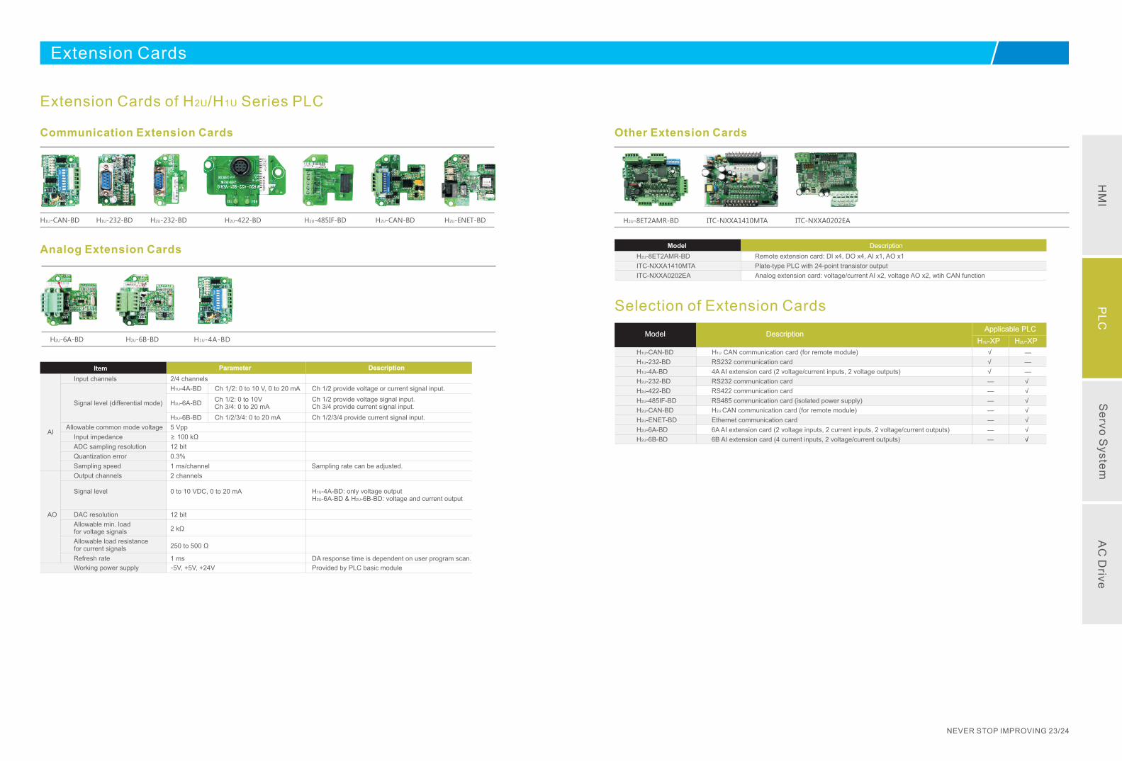
Extension Cards
Extension Cards of H2U/ Series PLCH1U
Communication Extension Cards
H2U-485IF-BDH2U-232-BD H2U-422-BD H2U-CAN-BD H2U-ENET-BD
Analog Extension Cards
H2U-6B-BDH2U-6A-BD
ITC-NXXA1410MTAH2U-8ET2AMR-BD
Other Extension Cards
ITC-NXXA0202EAH1U-232-BDH1U-CAN-BD
H1U-4A-BD
NEVER STOP IMPROVING 23/24
Allowable common mode voltage
Input impedance
ADC sampling resolution
Quantization error
Sampling speed
Output channels
Signal level
DAC resolution
Allowable min. load for voltage signals
Allowable load resistance for current signals
Refresh rate
Working power supply
Input channels
Signal level (differential mode)
AI
Item Parameter
2/4 channels
Ch 1/2: 0 to 10 V, 0 to 20 mA
Ch 1/2: 0 to 10VCh 3/4: 0 to 20 mA
Ch 1/2/3/4: 0 to 20 mA
5 Vpp
≥ 100 kΩ
12 bit
0.3%
1 ms/channel
2 channels
0 to 10 VDC, 0 to 20 mA
12 bit
2 kΩ
250 to 500 Ω
1 ms
-5V, +5V, +24V
Description
Ch 1/2 provide voltage or current signal input.
Ch 1/2 provide voltage signal input.Ch 3/4 provide current signal input.
Ch 1/2/3/4 provide current signal input.
Sampling rate can be adjusted.
H1U-4A-BD: only voltage outputH2U-6A-BD & H2U-6B-BD: voltage and current output
DA response time is dependent on user program scan.
Provided by PLC basic module
H1U-4A-BD
H2U-6A-BD
H2U-6B-BD
AO
Description
Remote extension card: DI x4, DO x4, AI x1, AO x1
Plate-type PLC with 24-point transistor output
Analog extension card: voltage/current AI x2, voltage AO x2, wtih CAN function
H2U-8ET2AMR-BD
ITC-NXXA1410MTA
ITC-NXXA0202EA
Model
Selection of Extension Cards
Description
H1U CAN communication card (for remote module)
RS232 communication card
4A AI extension card (2 voltage/current inputs, 2 voltage outputs)
RS422 communication card
RS485 communication card (isolated power supply)
H2U CAN communication card (for remote module)
Ethernet communication card
6A AI extension card (2 voltage inputs, 2 current inputs, 2 voltage/current outputs)
RS232 communication card
6B AI extension card (4 current inputs, 2 voltage/current outputs)
H2U-422-BD
H2U-485IF-BD
H2U-CAN-BD
H2U-ENET-BD
H2U-6A-BD
H2U-6B-BD
H1U-CAN-BD
H1U-232-BD
H1U-4A-BD
H2U-232-BD
ModelApplicable PLC
H1U-XP H2U-XP
√
√
√
—
—
—
—
—
—
—
—
—
—
√
√
√
√
√
√
√
HM
IP
LC
Se
rvo S
yste
mA
C D
rive

IS Series Servo System
IS Series Servo System
NEVER STOP IMPROVING 25/26
IS Series Servo System
NEVER STOP IMPROVING 27/28
A bandwidth at 700 Hz can be realized at a resolution of 2500 ppr, which satisfies general-purpose industrial automation requirements.
Response frequency 700 Hz
Applications: Textile industry, electric spark, line manipulator, electronic manufacturing equipment
-3
-10
Grain (dB)
500 700 Frequency (Hz)
700Hz
IS600P
Previous drives
IS600P Series Servo System
General-purpose Function-enhanced
IS620P Series Servo System
Ap
plic
atio
n F
ield
sS
afe
Pra
ctic
al
welding and cutting equipment, warp knitting machine, electronic manufacturing equipment, lithium equipment, printing industry, cable equipment, line manipulator, food production line, packaging production line, detection equipment, winding machine, material feeding machine, ceramic equipment, injection molding machine
Textile equipment, glass equipment, wire cutting, electric spark, machine, CNC, machine tool, miller, grinder, wood carving machine, glass machine, wire cutting, electric spark, welding and cutting equipment, warp knitting machine, electronic manufacturing equipment, LED industry, lithium equipment, joint manipulator, printing industry, cable equipment, line manipulator, food production line, packaging production line, detection equipment, winding machine, material feeding machine, ceramic equipment, injection molding machine, glass machine
Engraving and milling machine, carving machine, specular
Input/Output pulses: 4 Mpps
Low cogging torque
Overload capacity up to 3 times
Response frequency 700 Hz
Inte
llige
nt
-3
-10
Grain (dB)
500 1200 Frequency (Hz)
1.2kHz
IS600 Series Servo Drive
10,000p/r
1,048,576p/r
100 times
Hig
h P
erfo
rma
nce
Ric
h A
pp
lica
tion
Fu
nctio
ns
Input/Output pulses: 4 Mpps
Low cogging torque
Overload capacity up to 3 times
20 bit incremental encoder
Analog reference resolution: 16 bit (1/65536)
(customized function)
Response frequency 1.2 kHz
Convenient gain adjustment
Automatic/Manual notch filter
Automatic/Manual damping filter
Load inertia identification
Motor IP level IP65/67, satisfying water-proof and dust-proof requirements
CE certified
Optional safe torque off (STO) function
PDFF control coefficient (H08-24)
Various communication modes
Tailored motors for path tracking control
Downsized servo drives and motors
Disturbance torque compensation gain & filter time
Braking energy treatment
Torque limit switchover
Gain switchover
I/O signal distribution
Powerful monitoring software
Friction/Torque compensation
Interrupted position control
Multi-position control
Dual-PG full closed-loop control
Interrupted position control
CANlink communication
Electronic cam control
Gantry synchronization
Multi-position control
Dual-PG full closed-loop control
IS620 Series Servo Drive
High response control based on torque feedforward can reduce response delay. Optimal adjusting time of position can reach 1 ms.
Response frequency 1.2 kHz
Applications: LED industry, lithium industry, manipulator, machine tool
IS620P
Previous drives
IS620 Series Servo Drive
Inovance self-developed 20-bit encoder, with a resolution up to 1,048,576 pulses/revolutionThis encoder adapts the phase array technology and has excellent performance on response frequency, working temperature and reliability. This encoder uses resin materials, which helps on improving its anti-vibration performance.Working temperature of this encoder can reach up to
120, which helps the servo motor function to a
larger extent.
20 bit incremental encoder
Applications: machine tool, electronic manufacturing equipment, wood carving machine, packaging equipment, detection equipment, glass machinery
IS620P
Previous drives
IS620 Series Servo Drive
IS620P series servo drive is configured with two
analog channels AI1 and AI2 to satisfy both general
and high precision analog reference requirement.
Resolution of AI1 is 12 bit; resolution of AI2 can be
selected as 12 bit or 16 bit via software switch.
Analog reference resolution: 16 bit (1/65536)
Input voltage
Speed
Speed range: 0 to 6000 rpm
-10 V
10 V
Applications: engraving and milling machine, glassmachinery, electronic manufacturing equipment
Note: Analog reference with high precision
resolution is a customized function.
16 bit
HM
IP
LC
Se
rvo S
yste
mA
C D
rive
NEVER STOP IMPROVING 29/30
IS600P/IS620P Series Servo Drive
IS Series Servo System
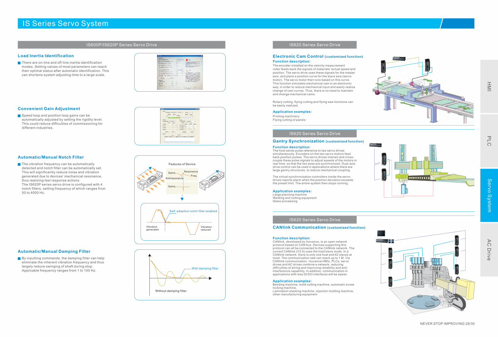
Load Inertia Identification
There are on-line and off-line inertia identification modes. Setting values of most parameters can reach their optimal status after automatic identification. This can shortens system adjusting time to a large scale.
Convenient Gain Adjustment
Speed loop and position loop gains can be automatically adjusted by setting the rigidity level. This could reduce difficulties of commissioning for different industries.
Automatic/Manual Notch Filter
The vibration frequency can be automatically detected and notch filter can be automatically set. This will significantly reduce noise and vibration generated due to devices’ mechanical resonance, thus realizing fast response actions. The IS620P series servo drive is configured with 4 notch filters, setting frequency of which ranges from 50 to 4000 Hz.
Automatic/Manual Damping Filter
By inputting commands, the damping filter can help eliminate the inherent vibration frequency and thus largely reduce swinging of shaft during stop. Applicable frequency ranges from 1 to 100 Hz.
Features of Device
Gains
Gains
Antiresonance
Resonance
Freq.
Self-adaptive notch filter enabled
Vibration generated
Vibration reduced
Without damping filter
With damping filter
IS620 Series Servo Drive
Rotary cutting, flying cutting and flying saw functions can be easily realized.
The encoder installed on the velocity measurement roller feeds back the signals of materials' actual speed and position. The servo drive uses these signals for the master axis, and plans a position curve for the slave axis (servo motor). The servo motor then runs based on this curve. This function simulates mechanical cam in an electronic way, in order to reduce mechanical input and easily realize change of cam curves. Thus, there is no need to maintain and change mechanical cams.
Printing machineryFlying cutting of panels
Electronic Cam Control (customized function)
Gantry Synchronization (customized function)
Function description:
Application examples:
Function description:
Application examples:
The host sends pulse reference to two servo drives simultaneously. Encoders on the two servo motors feed back position pulses. The servo drives interact and cross-couple these pulse signals to adjust speeds of the motors in real time, so that the two axes are synchronized. Dual-axis drive control can be used in applications where there are large gantry structures, to reduce mechanical coupling.
The virtual synchronization controllers inside the servo drives reports alarm when the position deviation exceeds the preset limit. The entire system then stops running.
Large planning machineWelding and cutting equipmentGlass processing
IS620 Series Servo Drive
CANlink Communication (customized function)
Function description:
Application examples:
CANlink, developed by Inovance, is an open network protocol based on CAN bus. Devices supporting this protocol can all be connected to the CANlink network. The current CANlink (V3.0) uses the host/slave mode. In a CANlink network, there is only one host and 62 slaves at most. The communication rate can reach up to 1 M. Via CANlink communication, Inovance HMIs, PLCs, servo drives and AC drives combine a network, reducing difficulties of wiring and improving reliability and anti-interference capability. In addition, communication in applications with less DI/DO interfaces will be easier.
Bending machine, mold cutting machine, automatic screw locking machine,Lamination stacking machine, injection molding machine, other manufacturing equipment
IS620 Series Servo Drive
HM
IP
LC
Se
rvo S
yste
mA
C D
rive
IS600P Series Servo System
NEVER STOP IMPROVING 31/32
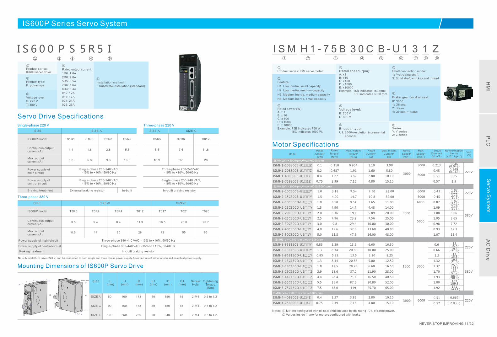
I S 6 0 0 P S 5 R 5 I① ② ③ ④ ⑤
①Product series: IS600 servo drive
②
Product type:P: pulse type
ISMH1(Vn=3000rpm,Vmax=6000rpm)
220VISMH1- 120B30CB-U Z 0.2 0.637 1.91 1.60 5.80 0.45 0.149(0.163)
ISMH1- 140B30CB-U 1Z 0.4 1.27 3.82 2.80 10.10 0.51 0.25
ISMH1- 175B30CB-U 1Z 0.75 2.39 7.16 4.80 15.10 0.57 1.3
ISMH2- Y10C30CB-U1 1.0 3.18 9.54 7.50 23.00 0.43 1.87(3.12)
ISMH2(Vn=3000rpm,Vmax=6000/5000rpm)
ISMH2- Y10C30CD-U1 1.0 3.18 9.54 3.65 11.00 0.87 1.87(3.12)
ISMH2- Y15C30CD-U1 1.5 4.90 14.7 4.48 14.00 1.09 2.46(3.71)
ISMH2- 1 Y20C30CD-U 1 2.0 6.36 19.1 5.89 20.00 1.08 3.06
ISMH2- 1 Y25C30CD-U 1 2.5 7.96 23.9 7.56 25.00 1.05 3.65
ISMH2- 1 Y30C30CD-U 1 3.0 9.8 29.4 10.00 30.00 0.98 7.72
ISMH2- 1 Y40C30CD-U 1 4.0 12.6 37.8 13.60 40.80 0.93 12.1
ISMH2- 1 Y50C30CD-U 1 5.0 15.8 47.6 16.00 48.00 1.07 15.4
380V
220V
ISMH3- D-U1 Y13C15C 1.3 8.34 20.85 5.00 12.50 1.32 19.3(21.8)
ISMH3- D-U1 Y18C15C 1.8 11.5 28.75 6.60 16.50 1.37 25.5(28)
ISMH3- Y85B15CB-U1 0.85 5.39 13.5 6.60 16.50 0.6 13(15.5)
ISMH3- Y13C15CB-U1 1.3 8.34 20.85 10.00 25.00 0.66 19.3(21.8)
2.9 18.6 37.2 11.90 28.00 1.70 55(57.2)ISMH3-29C15CD-U1 Z
ISMH3- 144C15CD-U Z 4.4 28.4 71.1 16.50 40.50 1.93 88.9(90.8)
ISMH3- 155C15CD-U Z 5.5 35.0 87.6 20.80 52.00 1.80 107(109.5)
ISMH3- 175C15CD-U Z 7.5 48.0 119 25.70 65.00 1.92 141(143.1)
220V
380V
ISMH3- Y85B15CD-U1 0.85 5.39 13.5 3.30 8.25 1.2 13(15.5)
ISMH2- Y15C30CB-U1 1.5 4.90 14.7 10.8 32.00 0.45 2.46(3.71)
ISMH3(Vn=1500rpm,Vmax=3000rpm)
ISMH4(Vn=3000rpm,Vmax=6000rpm)
3000
3000
1500
3000ISMH4- 440B30CB-U1 Z 0.4 1.27 3.82 2.80 10.10 0.51
ISMH1-10B30CB-U Z1 0.1 0.318 0.954 1.10 3.90 0.213 0.046(0.048)
6000
6000
6000
5000
3000
5000
6000
5000
I S M H 1 - 7 5 B 3 0 C B - U 1 3 1 Z① ② ③ ④ ⑤ ⑥ ⑦ ⑧ ⑨
220VISMH4- 475B30CB-U1 Z 0.75 2.39 7.16 4.80 15.10 0.57
(0.667)
(2.033)
③
Voltage level:S: 220 VT: 380 V
④
Rated output current:
1R6: 1.6A
2R8 2.8A
5R5 5.5A
7R6 7.6A
8R4 8.4A
012 12A
017 17A
021 21A
026 26A
:
:
:
:
:
:
:
:
⑤
Installation method:I: Substrate installation (standard)
Servo Drive Specifications
Mounting Dimensions of IS600P Servo Drive
IS600P model
Continuous output current (A)
Max. output current (A)
Power supply of main circuit
Power supply of control circuit
Braking treatment
S1R6
1.6
5.8
S2R8
2.8
9.3
S5R5
5.5
16.9
Single-phase 200-240 VAC,10%, 50/60 Hz-15% to +
Single-phase 200-240 VAC,-15% to +10%, 50/60 Hz
External braking resistor In-built
SIZE-A
SIZE-C SIZE-E
IS600P model
Continuous output current (A)
Max. output current (A)
T3R5
3.5
8.5
T5R4
5.4
14
T8R4
8.4
20
T012
11.9
28
T017
16.5
42
T021
20.8
55
T026
25.7
65
Three-phase 380 V
Three-phase 220 VSingle-phase 220 V
Power supply of main circuit Three-phase 380-440 VAC, -15% to +10%, 50/60 Hz
Power supply of control circuit Single-phase 380-440 VAC, -15% to +10%, 50/60 Hz
Braking treatment In-built braking resistor
Note: Model S5R5 drive (220 V) can be connected to both single and three phase power supply. User can select either one based on actual power supply.
SIZE
SIZE
S5R5
5.5
16.9
S7R6
7.6
17
S012
11.6
28
Three-phase 200-240 VAC,-15% to +10%, 50/60 Hz
Single-phase 200-240 VAC,-15% to +10%, 50/60 Hz
In-built braking resistor
SIZE-A SIZE-C
TighteningTorque(Nm)
ScrewHole
D1(mm)
H1(mm)
L1(mm)
D(mm)
H(mm)
Lmm)(
SIZE A 50 160 173 40 150 75 2-M4 0.6 to 1.2
SIZE C 90 160 183 80 150 75 2-M4 0.6 1.2 to
SIZE E 100 250 230 90 240 75 2-M4 0.6 1.2 to
SIZED
L
H
D1
L1
Screw hole
H1
S1R1
1.1
5.8
Model
Rated
Output*
(kW)
Rated
Torque*
(N•m)
Max. Instant
Torque*
(N•m)
Rated
Current*
(A)
Max. Instant
Current*(A)
Rated
Speed* ( )-1min
Max.
Speed* -1(min )
TorqueConstant( )N•m/A
Rotor RotationInertia
( )-4 2×10 kg•m
Volt.V)(
Notes: ① Motors configured with oil seal shall be used by de-rating 10% of rated power.
② are for motors configured with brake. Values inside ( )
①
Product series: ISM servo motor
②
Feature:
H1: Low inertia, small capacity
H2:
H3:
H4:
Low inertia, medium capacity
Medium inertia, medium capacity
Medium inertia, small capacity
⑤
Voltage level:B: 200 VD: 400 V
⑥
Encoder type: U1: 2500-resolution incremental encoder
⑦
Shaft connection mode:1: Protruding shaft3: Solid shaft with key and thread
④
Rated speed (rpm):A: x1B 10C 100D 1000E 10000Example: 15B indicates 150 rpm; 30C indicates 3000 rpm.
: x: x: x: x
③Rated power W):A: x 1B: 10C: 100D: 1000E: 10000Example: 75B indicates 750 W; 15C indicates 1500 W.
(
x x x x
⑧
Brake, gear box & oil seal:
0: None1: Oil seal2: Brake4: Oil seal + brake
⑨Series:Y: Y seriesZ: Z series
Motor Specifications
HM
IP
LC
Se
rvo S
yste
mA
C D
rive
NEVER STOP IMPROVING 33/34
ISMH1(Vn=3000rpm,Vmax=6000rpm)
200VISMH1- 220B30CB-U Z 0.2 0.637 1.91 1.60 5.80 0.45 0.149(0.163)
ISMH1- 240B30CB-U 1Z 0.4 1.27 3.82 2.80 10.10 0.51 0.25
ISMH1- 275B30CB-U 1Z 0.75 2.39 7.16 4.80 15.10 0.57 1.3
ISMH2- 2 Y10C30CB-U 1.0 3.18 9.54 7.50 23.00 0.43 1.87(3.12)
ISMH2(Vn=3000rpm,Vmax=6000/5000rpm)
ISMH2- 2 Y10C30CD-U 1.0 3.18 9.54 3.65 11.00 0.87 1.87(3.12)
ISMH2- 2 Y15C30CD-U 1.5 4.90 14.7 4.48 14.00 1.09 2.46(3.71)
400V
200V
ISMH3- D-U2 Y13C15C 1.3 8.34 20.85 5.00 12.50 1.32 19.3(21.8)
ISMH3- D-U2 Y18C15C 1.8 11.5 28.75 6.60 16.50 1.37 25.5(28)
ISMH3- 2 Y85B15CB-U 0.85 5.39 13.5 6.60 16.50 0.6 13(15.5)
ISMH3- 2 Y13C15CB-U 1.3 8.34 20.85 10.00 25.00 0.66 19.3(21.8)
200V
ISMH3- 2 Y85B15CD-U 0.85 5.39 13.5 3.30 8.25 1.2 13(15.5)
ISMH2- 2 Y15C30CB-U 1.5 4.90 14.7 10.8 32.00 0.45 2.46(3.71)
ISMH3(Vn=1500rpm,Vmax=3000rpm)
ISMH4(Vn=3000rpm,Vmax=6000rpm)
3000
3000
1500
3000ISMH4- 240B30CB-U Z 0.4 1.27 3.82 2.80 10.10 0.51
ISMH1-10B30CB-U Z2 0.1 0.318 0.954 1.10 3.90 0.213 0.046(0.048)
6000
6000
6000
3000
5000
6000
5000
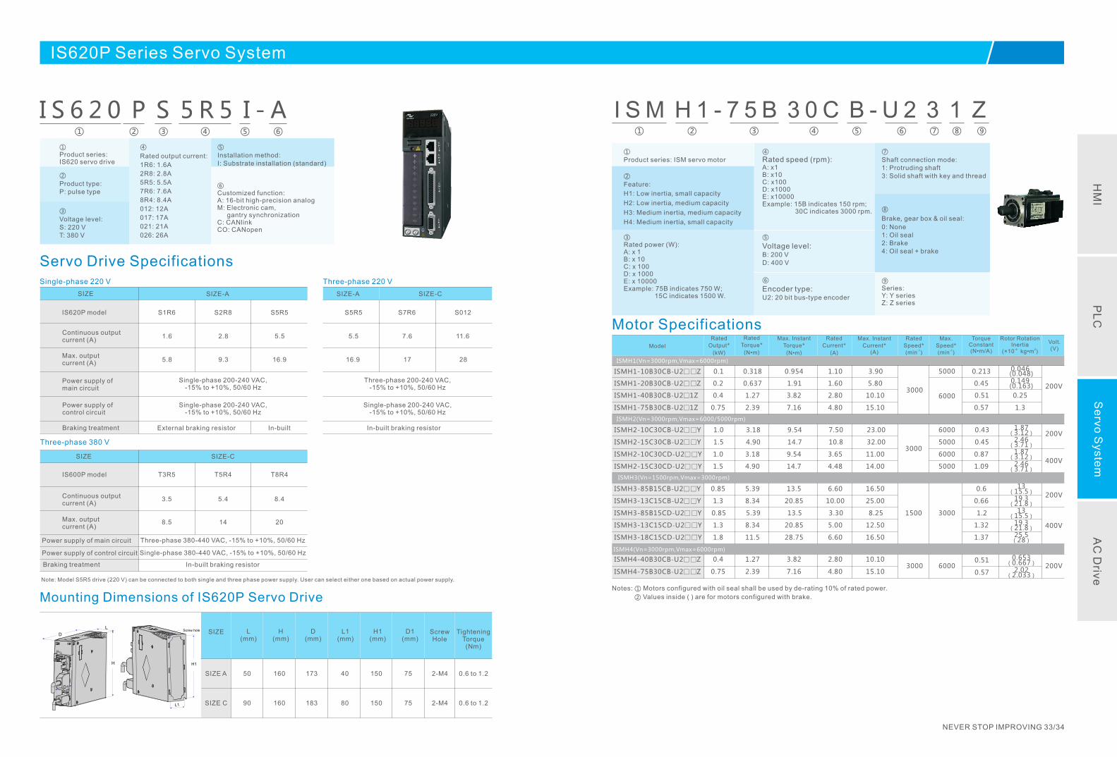
I S M H 1 - 7 5 B 3 0 C B - U 2 3 1 Z① ② ③ ④ ⑤ ⑥ ⑦ ⑧ ⑨
200VISMH4- 275B30CB-U Z 0.75 2.39 7.16 4.80 15.10 0.57
0.653(0.667)
2.02 (2.033)
5000
400V
I S 6 2 0 P S 5 R 5 I - A① ② ③ ④ ⑤ ⑥
IS620P Series Servo System
①Product series: IS620 servo drive
②
Product type:P: pulse type
③
Voltage level:S: 220 VT: 380 V
④
Rated output current:
1R6: 1.6A
2R8 2.8A
5R5 5.5A
7R6 7.6A
8R4 8.4A
012 12A
017 17A
021 21A
026 26A
:
:
:
:
:
:
:
:
⑤
Installation method:I: Substrate installation (standard)
Servo Drive Specifications
Mounting Dimensions of IS620P Servo Drive
IS620P model
Continuous output current (A)
Max. output current (A)
Power supply of main circuit
Power supply of control circuit
Braking treatment
S1R6
1.6
5.8
S2R8
2.8
9.3
S5R5
5.5
16.9
Single-phase 200-240 VAC,10%, 50/60 Hz-15% to +
Single-phase 200-240 VAC,-15% to +10%, 50/60 Hz
External braking resistor In-built
SIZE-A
SIZE-C
IS600P model
Continuous output current (A)
Max. output current (A)
T3R5
3.5
8.5
T5R4
5.4
14
T8R4
8.4
20
Three-phase 380 V
Three-phase 220 VSingle-phase 220 V
Power supply of main circuit Three-phase 380-440 VAC, -15% to +10%, 50/60 Hz
Power supply of control circuit Single-phase 380-440 VAC, -15% to +10%, 50/60 Hz
Braking treatment In-built braking resistor
Note: Model S5R5 drive (220 V) can be connected to both single and three phase power supply. User can select either one based on actual power supply.
SIZE
SIZE
S5R5
5.5
16.9
S7R6
7.6
17
S012
11.6
28
Three-phase 200-240 VAC,-15% to +10%, 50/60 Hz
Single-phase 200-240 VAC,-15% to +10%, 50/60 Hz
In-built braking resistor
SIZE-A SIZE-C
TighteningTorque(Nm)
ScrewHole
D1(mm)
H1(mm)
L1(mm)
D(mm)
H(mm)
Lmm)(
SIZE A 50 160 173 40 150 75 2-M4 0.6 to 1.2
SIZE C 90 160 183 80 150 75 2-M4 0.6 1.2 to
SIZED
L
H
D1
L1
Screw hole
H1
⑥Customized function:A: 16-bit high-precision analog M: Electronic cam, gantry synchronizationC: CANlinkCO: CANopen
Model
Rated
Output*
(kW)
Rated
Torque*
(N•m)
Max. Instant
Torque*
(N•m)
Rated
Current*
(A)
Max. Instant
Current*(A)
Rated
Speed* ( )-1min
Max.
Speed* -1(min )
TorqueConstant( )N•m/A
Rotor RotationInertia
( )-4 2×10 kg•m
Volt.V)(
①
Product series: ISM servo motor
②
Feature:
H1: Low inertia, small capacity
H2:
H3:
H4:
Low inertia, medium capacity
Medium inertia, medium capacity
Medium inertia, small capacity
⑤
Voltage level:B: 200 VD: 400 V
⑥
Encoder type: U2: 20 bit bus-type encoder
⑦
Shaft connection mode:1: Protruding shaft3: Solid shaft with key and thread
④
Rated speed (rpm):A: x1B 10C 100D 1000E 10000Example: 15B indicates 150 rpm; 30C indicates 3000 rpm.
: x: x: x: x
③Rated power W):A: x 1B: 10C: 100D: 1000E: 10000Example: 75B indicates 750 W; 15C indicates 1500 W.
(
x x x x
⑧
Brake, gear box & oil seal:
0: None1: Oil seal2: Brake4: Oil seal + brake
⑨Series:Y: Y seriesZ: Z series
Motor Specifications
Notes: ① Motors configured with oil seal shall be used by de-rating 10% of rated power.
② are for motors configured with brake. Values inside ( )
HM
IP
LC
Se
rvo S
yste
mA
C D
rive

MD Series AC Drive
MD Series AC Drive
NEVER STOP IMPROVING 35/36

MD Series AC Drive
Input voltage
Applicable motor (kW)
Input current (A)
Output current (A)
Power capacity (kVA)
Max. frequency
Control mode
Startup torque
Speed stabilizing precision
Torque control precision
Overload capacity
Options
Communication
Technical data
Technical specifications
AC Drive
Single-phase 220V, 3-phase 380V
0.4~450kW
5.4~883
2.3~820
1.0~630
630 Hz (3200 Hz at maximum for customized models)
V/F control, flux vector control
150%
±1%
G type: 150% rated current for 60sP type: 130% rated current for 60s
-
In-built/external braking unit, energy feedback unit, external keypad, extended cable
Modbus
Note: For MD280 AC drive, 15 kW and below models are configured with an in-built braking unit.
Single-phase 220V, 3-phase 380V, 3-phase 220V
0.4~ kW18.5
1.9~38.5
1.5~37.0
1.0~24.0
500 Hz (V/F), 300 Hz (SVC)
SVC, V/F control, V/F separated control
SVC: 0. 5Hz/150%V/F: 1Hz/100%
±0.5% (SVC), 1% (V/F)
150% rated current for 1 min;180% rated current for 2s
-
I/O, CANlink, CANopen extension cards,External keypad
Modbus RTU, CANlink CANopen,
NEVER STOP IMPROVING 37/38
MD210 Series Economic General-purpose AC Drive
Application fields:Glass machinery, wood-working machinery, electronic equipment, food machinery, small fans and pumps, conveyors, blenders, grinding millers, medical centrifuges, small hoisters, stereo garages, farm machinery, automatic rolling doors
Features:Compact size, convenient operation and maintenance,In-built PID, multi-speed PLC function, virtual I/O, Modbus communication, configured with braking unit
Single-phase 220V, 3-phase 380V, 3-phase 220V
0.4~ kW2.2
1.9~23
1.5~9.6
1.0~4.0
500 Hz
V/F control
1 Hz/100%
1%
150% rated current for 1 min;180% rated current for 2s
-
Modbus
None
MD310 Series Multi-function Vector AC Drive
Application fields:Ceramic machinery, wood-working machinery, small machine tools, grinders, drillers, millers, glass machinery, textile machinery, ribbon looms, circular knitting machines, small fans and pumps, conveyors, stereo garages, coating equipment, small hoisters, farm machinery, automatic rolling doors, grinding millers, medical centrifuges.
Features:Support high-performance current vector control, V/F control, and V/F separated control; Built-in PID, simple PLC function, swing frequency, virtual I/O function, four groups of motor parameters;RS485 communication port supports Modbus RTU communication; CANopen and CANlink communication can be extended.Configured with braking unit
MD280 Series General-purpose AC Drive
Application fields:Fan and pump, ceramic equipment, dyeing and finishing equipment, dry cleaning equipment, transmission device, etc
Features:PID control, multi-point V/F curve setting, Oscillation suppression function, RS485 communication,Rapid current limit, rapid start/stop function
HM
IP
LC
Se
rvo S
yste
mA
C D
rive
MD210 Series Economic General-purpose AC Drive
Power range: 0.4 to 2.2 kW;
Compact structure and feasibility of parallel installation reduce size of control cabinet;
Easy and simple to use;
Convenient maintenance: host computer software facilitates parameter management;
Built-in PID, multi-speed PLC, virtual I/O function, Modbus communication.
Features:
Technical Data
1.0
1.5
3.0
4.0
1.5
3.0
4.0
5.9
1.2
1.5
3.0
4.0
5.4
8.2
14.0
23.0
3.4
5.0
5.8
10.5
1.9
3.4
5.0
5.8
2.3
4.0
7.0
9.6
2.1
3.8
5.1
9.0
1.5
2.1
3.8
5.1
0.4
0.75
1.5
2.2
0.4
0.75
1.5
2.2
0.4
0.75
1.5
2.2
Power Capacity (kVA)
Input Current (A)
Output Current (A)
Power of Adaptable MotorAC Drive Model
(kW) (HP)
0.5
1
2
3
0.5
1
2
3
0.5
1
2
3
Single-phase 220V, 50/60 Hz
MD210S0.4B
MD210S0.7B
MD210S1.5B
MD210S2.2B
Three-phase 220V, 50/60 Hz
MD210-2T0.4B
MD210-2T0.7B
MD210-2T1.1B
MD210-2T2.2B
Three-phase 380V, 50/60 Hz
MD210T0.4B
MD210T0.7B
MD210T1.5B
MD210T2.2B
1.0
1.5
3.0
4.0
1.5
3.0
4.0
5.9
8.9
17.0
21.0
1.0
1.5
3.0
4.0
5.9
8.9
11.0
17.0
21.0
24.0
5.4
8.2
14.0
23.0
3.4
5.0
5.8
10.5
14.6
26.0
35.0
1.9
3.4
5.0
5.8
10.5
14.6
20.5
26.0
35.0
38.5
2.3
4.0
7.0
9.6
2.1
3.8
5.1
9.0
13.0
25.0
32.0
1.5
2.1
3.8
5.1
9.0
13.0
17.0
25.0
32.0
37.0
0.4
0.75
1.5
2.2
0.4
0.75
1.5
2.2
3.7
5.5
7.5
0.4
0.75
1.5
2.2
3.7
5.5
7.5
11.0
15.0
18.5
0.5
1
2
3
0.5
1
2
3
5
7.5
10
0.5
1
2
3
5
7.5
10
15
20
25
Single-phase 220V, 50/60 Hz
MD310S0.4B
MD310S0.7B
MD310S1.5B
MD310S2.2B
Three-phase 220V, 50/60 Hz
MD310-2T0.4B
MD310-2T0.75B
MD310-2T1.1B
MD310-2T2.2B
MD310-2T3.7B
MD310-2T5.5B
MD310-2T7.5B
Three-phase 380V, 50/60 Hz
MD310T0.4B
MD310T0.7B
MD310T1.5B
MD310T2.2B
MD310T3.7B
MD310T5.5B
MD310T7.5B
MD310T11B
MD310T15B
MD310T18.5B
NEVER STOP IMPROVING 39/40
MD310 Series Multi-function Vector AC Drive
Application fields:
Glass machinery, wood-working machinery, electronic equipment, food machinery, small
fans and pumps, conveyors, blenders, grinding millers, medical centrifuges, small hoisters,
stereo garages, farm machinery, automatic rolling doors
Power range: 0.4 to 18.5 kW;
Support high-performance current vector control, V/F control, and V/F separated control;
Built-in PID, simple PLC function, swing frequency, virtual I/O function, four groups of
motor parameters;
Rs485 communication port supports Modbus RTU communication; CANopen and
CANlink communication can be extended.
Features:
Technical Data
Application fields:
Ceramic machinery, wood-working machinery, small machine tools, grinders, drillers,
millers, glass machinery, textile machinery, ribbon looms, circular knitting machines, small
fans and pumps, conveyors, stereo garages, coating equipment, small hoisters, farm
machinery, automatic rolling doors, grinding millers, medical centrifuges.
Power Capacity (kVA)
Input Current (A)
Output Current (A)
Power of Adaptable MotorAC Drive Model
(kW) (HP)
HM
IP
LC
Se
rvo S
yste
mA
C D
rive
MD280 Series General-purpose AC Drive
MD280NS0.4GB
MD280NS0.7GB
MD280NS1.5GB
MD280NS2.2GB
MD280NT0.7GB
MD280NT1.5GB
MD280NT2.2GB
MD280NT3.7GB/5.5PB
MD280NT5.5GB/7.5PB
MD280NT7.5GB/11PB
MD280NT11GB/15PB
MD280NT15GB/18.5PB
MD280NT18.5G/22P
MD280NT22G/30P
MD280NT30G/37P
MD280NT37G/45P
MD280NT45G/55P
MD280NT55G/75P
MD280NT75G/90P
MD280NT90G/110P
MD280NT110G/132PH
MD280NT132G/160PH
MD280NT160G/200PH
MD280NT200G/220P
MD280NT220G/250P
MD280NT250G/280P
MD280NT280G/315P
MD280NT315G/355P
MD280NT355G/400P
MD280NT400G/450P
1.0
1.5
3.0
4.0
1.5
3.0
4.0
8.9
11.0
17.0
21.0
24.0
30.0
40.0
57.0
69.0
85.0
114.0
134.0
160.0
192.0
231.0
250.0
280.0
355.0
396.0
445.0
500.0
565.0
630.0
5.4
8.2
14.0
23.0
3.4
5.0
5.8
14.6
20.5
26.0
35.0
38.5
46.5
62.0
76.0
92.0
113.0
157.0
180.0
214.0
256.0
307.0
385.0
430.0
468.0
525.0
590.0
665.0
785.0
883.0
2.3
4.0
7.0
9.6
2.1
3.8
5.1
9.0/13.0
13.0/17.0
17.0/25.0
25.0/32.0
32.0/37.0
37.0/45.0
45.0/60.0
60.0/75.0
75.0/91.0
91.0/112.0
112.0/150.0
150.0/176.0
176.0/210.0
210.0/253.0
253.0/304.0
304.0/377.0
377.0/426.0
426.0/465.0
465.0/520.0
520.0/585.0
585.0/650.0
650.0/725.0
752.0/820.0
0.4
0.75
1.5
2.2
0.75
1.5
2.2
3.7/5.5
5.5/7.5
7.5/11
11/15
15/18.5
18.5/22
22/30
30/37
37/45
45/55
55/75
75/90
90/110
110/132
132/160
160/200
200/220
220/250
250/280
280/315
315/355
355/400
400/450
Three-phase 380V,Range: -15% to 20%
Single-phase 220V,Range: -15% to 20%
Input VoltagePower Capacity
(kVA)Input Current
(A)Rated Output Current (A)
Adaptable Motor (kW)
Technical Data
NEVER STOP IMPROVING 41/42
Functions and Performance
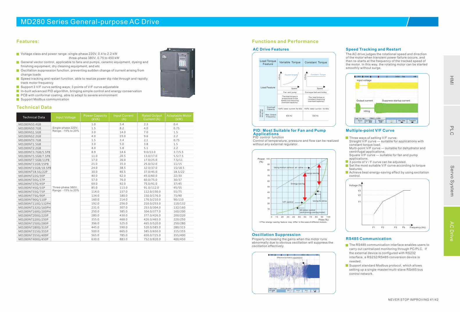
Voltage class and power range: single-phase 220V, 0.4 to 2.2 kW
three-phase 380V, 0.75 to 450 kW
General vector control, applicable to fans and pumps, ceramic equipment, dyeing and
finishing equipment, dry cleaning equipment, and etc
Oscillation suppression function, preventing sudden change of current arising from
change loads
Speed tracking and restart function, able to realize power dip ride through and rapidly
track motor frequency
Support 3 V/F curve setting ways; 3 points of V/F curve adjustable
In-built advanced PID algorithm, bringing simple control and energy conservation
PCB with conformal coating, able to adapt to severe environment
Support Modbus communication
Features:
Technical Data
AC Drive Features
Load Feature
Overload Capacity
Max. Output Frequency 630 Hz 630 Hz
130 rated current for 60s%
The load torque is proportional to the
speed (not requiringoverload capacity).
The lconstant (requiring overload capacity).
oad torque is
Conveyer belt and trolleyFan and pump
Load TorqueFeature
Variable Torque Constant Torque
To
rqu
e
To
rqu
e
Speed Speed
Square torque Constant Torque
AC
Driv
e
Fe
atu
res
150% for 60srated current
PID: Most Suitable for Fan and Pump Applications
Control of temperature, pressure and flow can be realized without any external regulator.
PID control function
Oscillation Suppression Properly increasing the gains when the motor runs abnormally due to obvious oscillation will suppress the oscillation effectively.
Effective oscillation suppression
100
90
80
70
60
50
40
30
20
10
0 1 0 2 0 3 0 4 0 5 0 6 0 7 0 8 0 9 0 1 0 0
Using motion valve or air valve
Energy-saving
Energy-saving
V/F control
AC drive control(auto energy-saving mode)
Using AC drive
Power
(%)
※The energy-saving feature may differ in the case of different motors.Flow (%)
Speed Tracking and RestartThe AC drive judges the rotational speed and direction of the motor when transient power failure occurs, and then re-starts at the frequency of the tracked speed of the motor. In this way, the rotating motor can be started smoothly without surge.
Input voltage
Output current Suppress startup current
Idling
Multiple-point V/F Curve
Three ways of setting V/F curve:Straight V/F curve — suitable for applications with constant torque load.Multi-point V/F curve — suitable for dehydrator and centrifugal applications.Square V/F curve — suitable for fan and pump applications.3 points of V / F curve can be adjusted.Set the most suitable V/F curve according to torque features.Achieve best energy-saving effect by using excitation control.
Voltage (%)
V3
V2
V1
F1 F2 F3 Fb Frequency (Hz)
RS485 Communication
The RS485 communication interface enables users to
carry out centralized monitoring through PC/PLC. If
the external device is configured with RS232
interface, a RS232/RS485 conversion device is
needed.
Support standard Modbus protocol, which allows
setting up a single-master/multi-slave RS485 bus
control network.
HM
IP
LC
Se
rvo S
yste
mA
C D
rive


![FA Equipment for Beginners(HMIs) THA.ppt [互換モード] · CPU PLC HMI PLC I-IMI "HMI HMI HMI FA Equipment for Beginners(HMIs) THA 1.1 HMI](https://img.pdfslide.net/doc/110x75/5bd44ddf09d3f209338bbd79/fa-equipment-for-beginnershmis-thappt-cpu-plc-hmi-plc-i-imi.jpg)