Embed Size (px)
Citation preview
© KEMET Electronics Corporation • P.O. Box 5928 • Greenville, SC 29606 • 864-963-6300 • www.kemet.com F3023_F43 • 3/16/2018 1One world. One KEMET
Benefits
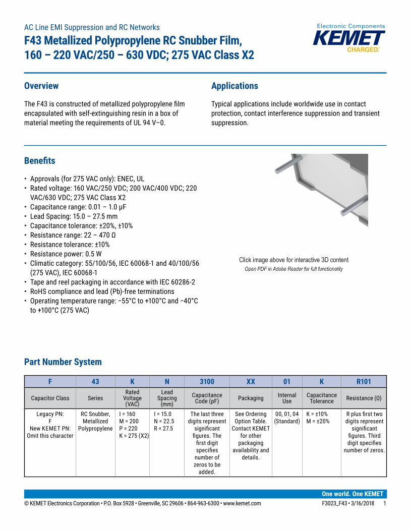
• Approvals (for 275 VAC only): ENEC, UL• Rated voltage: 160 VAC/250 VDC; 200 VAC/400 VDC; 220
VAC/630 VDC; 275 VAC Class X2• Capacitance range: 0.01 – 1.0 µF • Lead Spacing: 15.0 – 27.5 mm• Capacitance tolerance: ±20%, ±10%• Resistancerange:22–470Ω• Resistance tolerance: ±10%• Resistance power: 0.5 W• Climatic category: 55/100/56, IEC 60068-1 and 40/100/56
(275 VAC), IEC 60068-1• Tape and reel packaging in accordance with IEC 60286-2• RoHS compliance and lead (Pb)-free terminations• Operatingtemperaturerange:−55°Cto+100°Cand−40°Cto+100°C(275VAC)
Overview
TheF43isconstructedofmetallizedpolypropylenefilmencapsulated with self-extinguishing resin in a box of material meeting the requirements of UL 94 V–0.
Applications
Typical applications include worldwide use in contact protection, contact interference suppression and transient suppression.
AC Line EMI Suppression and RC Networks
F43 Metallized Polypropylene RC Snubber Film,160 – 220 VAC/250 – 630 VDC; 275 VAC Class X2
Part Number System
F 43 K N 3100 XX 01 K R101
Capacitor Class SeriesRated
Voltage (VAC)
Lead Spacing
(mm)Capacitance
Code (pF) Packaging Internal Use
Capacitance Tolerance Resistance(Ω)
Legacy PN: F
New KEMET PN: Omit this character
RC Snubber, Metallized
Polypropylene
I = 160M = 200P = 220K = 275 (X2)
I = 15.0 N = 22.5 R = 27.5
The last three digits represent
significantfigures.Thefirstdigitspecifies
number of zeros to be
added.
See Ordering Option Table.
Contact KEMET for other
packaging availability and
details.
00, 01, 04 (Standard)
K = ±10% M = ±20%
Rplusfirsttwodigits represent
significantfigures.Thirddigitspecifies
number of zeros.
© KEMET Electronics Corporation • P.O. Box 5928 • Greenville, SC 29606 • 864-963-6300 • www.kemet.com F3023_F43 • 3/16/2018 2
Film Capacitors – AC Line EMI Suppression and RC NetworksF43 Metallized Polypropylene RC Snubber Film, 160 – 220 VAC/250 – 630 VDC; 275 VAC Class X2
Ordering Options Table
Lead SpacingNominal
(mm)Type of Leads and Packaging Lead Length
(mm)
Lead and Packaging
Code
1522.527.5
Standard Lead and Packaging Options
Bulk (Bag) – Short leads 4+2/−0 00Ammo Pack H0 = 18.5 ±0.5 DQ
Other Lead and Packaging Options
Tape & Reel (Large Reel Ø = 500 mm) H0 = 18.5 ±0.5 CKBulk (Bag) – Long leads 30+5/−0 40Bulk (Bag) – Long leads 25+2/−1 50
Bulk (Bag) – Insulated rigid leads 30+5/-0(sp8±2) 51Bulk(Bag)–Insulatedflexibleleads 150 ±5 (sp 8 ±2) 52
Contact KEMET for availability and details for special leads or packing.
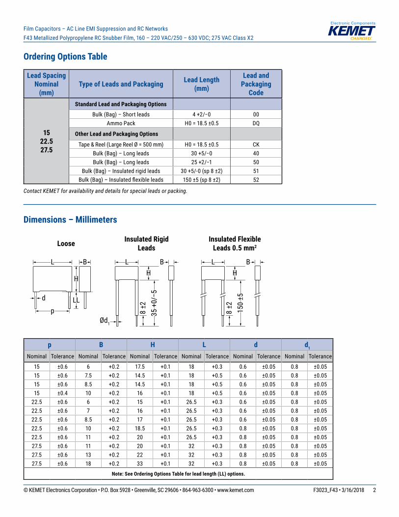
Dimensions – Millimeters
d
8 ±2
8 ±2
Ød1
Loose Insulated RigidLeads
Insulated FlexibleLeads 0.5 mm2
BL L
HH
LLp 35
+0/−5
B LH
B
150
±5
p B H L d d1 Nominal Tolerance Nominal Tolerance Nominal Tolerance Nominal Tolerance Nominal Tolerance Nominal Tolerance
15 ±0.6 6 +0.2 17.5 +0.1 18 +0.3 0.6 ±0.05 0.8 ±0.0515 ±0.6 7.5 +0.2 14.5 +0.1 18 +0.5 0.6 ±0.05 0.8 ±0.0515 ±0.6 8.5 +0.2 14.5 +0.1 18 +0.5 0.6 ±0.05 0.8 ±0.0515 ±0.4 10 +0.2 16 +0.1 18 +0.5 0.6 ±0.05 0.8 ±0.05
22.5 ±0.6 6 +0.2 15 +0.1 26.5 +0.3 0.6 ±0.05 0.8 ±0.0522.5 ±0.6 7 +0.2 16 +0.1 26.5 +0.3 0.6 ±0.05 0.8 ±0.0522.5 ±0.6 8.5 +0.2 17 +0.1 26.5 +0.3 0.6 ±0.05 0.8 ±0.0522.5 ±0.6 10 +0.2 18.5 +0.1 26.5 +0.3 0.8 ±0.05 0.8 ±0.0522.5 ±0.6 11 +0.2 20 +0.1 26.5 +0.3 0.8 ±0.05 0.8 ±0.0527.5 ±0.6 11 +0.2 20 +0.1 32 +0.3 0.8 ±0.05 0.8 ±0.0527.5 ±0.6 13 +0.2 22 +0.1 32 +0.3 0.8 ±0.05 0.8 ±0.0527.5 ±0.6 18 +0.2 33 +0.1 32 +0.3 0.8 ±0.05 0.8 ±0.05
Note: See Ordering Options Table for lead length (LL) options.
© KEMET Electronics Corporation • P.O. Box 5928 • Greenville, SC 29606 • 864-963-6300 • www.kemet.com F3023_F43 • 3/16/2018 3
Film Capacitors – AC Line EMI Suppression and RC NetworksF43 Metallized Polypropylene RC Snubber Film, 160 – 220 VAC/250 – 630 VDC; 275 VAC Class X2
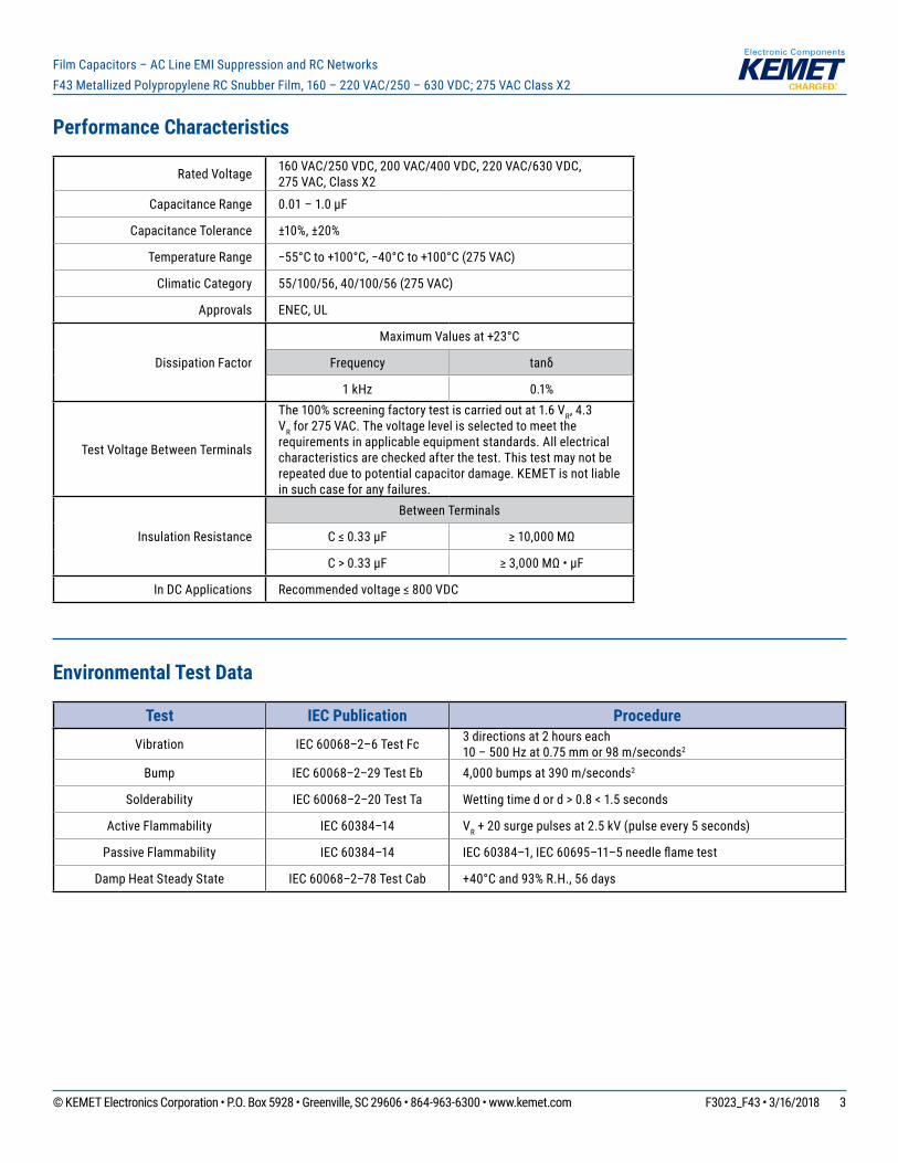
Performance Characteristics
Rated Voltage 160 VAC/250 VDC, 200 VAC/400 VDC, 220 VAC/630 VDC, 275 VAC, Class X2
Capacitance Range 0.01 – 1.0 µF
Capacitance Tolerance ±10%, ±20%
Temperature Range −55°Cto+100°C,−40°Cto+100°C(275VAC)
Climatic Category 55/100/56, 40/100/56 (275 VAC)
Approvals ENEC, UL
Dissipation Factor
MaximumValuesat+23°C
Frequency tanδ
1 kHz 0.1%
Test Voltage Between Terminals
The 100% screening factory test is carried out at 1.6 VR, 4.3 VR for 275 VAC. The voltage level is selected to meet the requirements in applicable equipment standards. All electrical characteristics are checked after the test. This test may not be repeated due to potential capacitor damage. KEMET is not liable in such case for any failures.
Insulation Resistance
Between Terminals
C≤0.33µF ≥10,000MΩ
C > 0.33 µF ≥3,000MΩ•µF
In DC Applications Recommendedvoltage≤800VDC
Environmental Test Data
Test IEC Publication Procedure
Vibration IEC 60068–2–6 Test Fc 3 directions at 2 hours each 10 – 500 Hz at 0.75 mm or 98 m/seconds2
Bump IEC 60068–2–29 Test Eb 4,000 bumps at 390 m/seconds2
Solderability IEC 60068–2–20 Test Ta Wetting time d or d > 0.8 < 1.5 seconds
Active Flammability IEC 60384–14 VR+20surgepulsesat2.5kV(pulseevery5seconds)
Passive Flammability IEC 60384–14 IEC60384–1,IEC60695–11–5needleflametest
Damp Heat Steady State IEC 60068–2–78 Test Cab +40°Cand93%R.H.,56days
© KEMET Electronics Corporation • P.O. Box 5928 • Greenville, SC 29606 • 864-963-6300 • www.kemet.com F3023_F43 • 3/16/2018 4
Film Capacitors – AC Line EMI Suppression and RC NetworksF43 Metallized Polypropylene RC Snubber Film, 160 – 220 VAC/250 – 630 VDC; 275 VAC Class X2
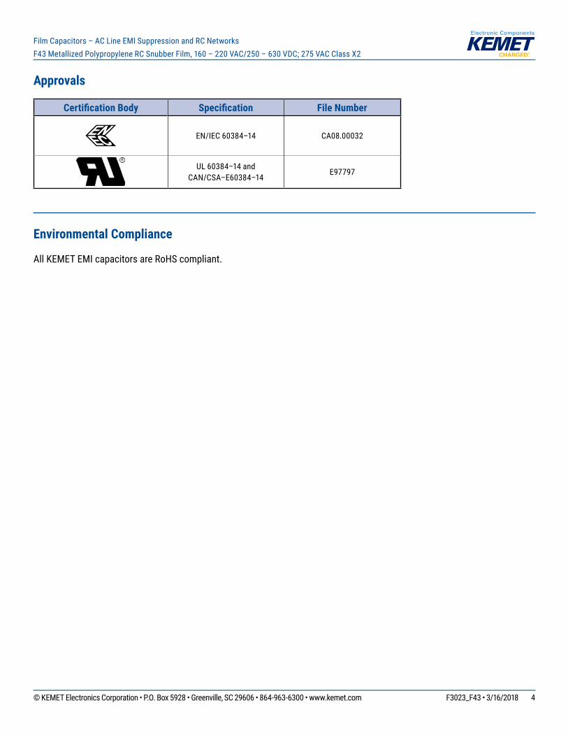
Approvals
Certification Body Specification File Number
EN/IEC 60384–14 CA08.00032
UL 60384–14 and CAN/CSA–E60384–14
E97797
Environmental Compliance
All KEMET EMI capacitors are RoHS compliant.
© KEMET Electronics Corporation • P.O. Box 5928 • Greenville, SC 29606 • 864-963-6300 • www.kemet.com F3023_F43 • 3/16/2018 5
Film Capacitors – AC Line EMI Suppression and RC NetworksF43 Metallized Polypropylene RC Snubber Film, 160 – 220 VAC/250 – 630 VDC; 275 VAC Class X2
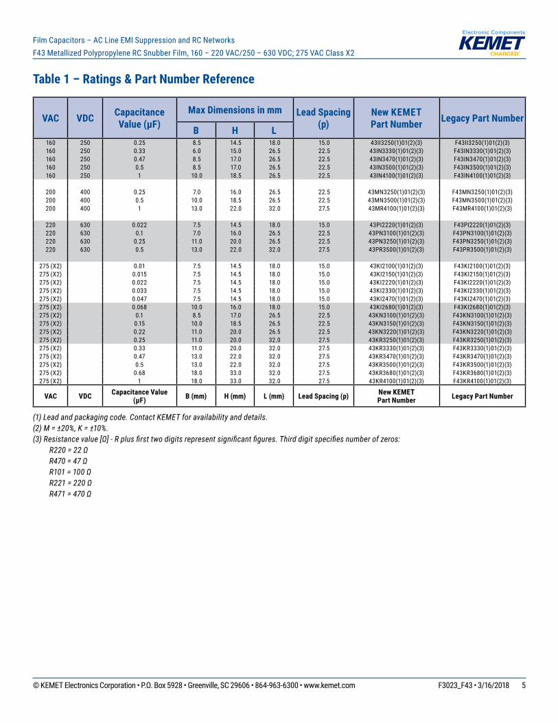
Table 1 – Ratings & Part Number Reference
VAC VDC Capacitance Value (µF)
Max Dimensions in mm Lead Spacing (p)
New KEMETPart Number Legacy Part Number
B H L160 250 0.25 8.5 14.5 18.0 15.0 43II3250(1)01(2)(3) F43II3250(1)01(2)(3)160 250 0.33 6.0 15.0 26.5 22.5 43IN3330(1)01(2)(3) F43IN3330(1)01(2)(3)160 250 0.47 8.5 17.0 26.5 22.5 43IN3470(1)01(2)(3) F43IN3470(1)01(2)(3)160 250 0.5 8.5 17.0 26.5 22.5 43IN3500(1)01(2)(3) F43IN3500(1)01(2)(3)160 250 1 10.0 18.5 26.5 22.5 43IN4100(1)01(2)(3) F43IN4100(1)01(2)(3)
200 400 0.25 7.0 16.0 26.5 22.5 43MN3250(1)01(2)(3) F43MN3250(1)01(2)(3)200 400 0.5 10.0 18.5 26.5 22.5 43MN3500(1)01(2)(3) F43MN3500(1)01(2)(3)200 400 1 13.0 22.0 32.0 27.5 43MR4100(1)01(2)(3) F43MR4100(1)01(2)(3)
220 630 0.022 7.5 14.5 18.0 15.0 43PI2220(1)01(2)(3) F43PI2220(1)01(2)(3)220 630 0.1 7.0 16.0 26.5 22.5 43PN3100(1)01(2)(3) F43PN3100(1)01(2)(3)220 630 0.25 11.0 20.0 26.5 22.5 43PN3250(1)01(2)(3) F43PN3250(1)01(2)(3)220 630 0.5 13.0 22.0 32.0 27.5 43PR3500(1)01(2)(3) F43PR3500(1)01(2)(3)
275 (X2) 0.01 7.5 14.5 18.0 15.0 43KI2100(1)01(2)(3) F43KI2100(1)01(2)(3)275 (X2) 0.015 7.5 14.5 18.0 15.0 43KI2150(1)01(2)(3) F43KI2150(1)01(2)(3)275 (X2) 0.022 7.5 14.5 18.0 15.0 43KI2220(1)01(2)(3) F43KI2220(1)01(2)(3)275 (X2) 0.033 7.5 14.5 18.0 15.0 43KI2330(1)01(2)(3) F43KI2330(1)01(2)(3)275 (X2) 0.047 7.5 14.5 18.0 15.0 43KI2470(1)01(2)(3) F43KI2470(1)01(2)(3)275 (X2) 0.068 10.0 16.0 18.0 15.0 43KI2680(1)01(2)(3) F43KI2680(1)01(2)(3)275 (X2) 0.1 8.5 17.0 26.5 22.5 43KN3100(1)01(2)(3) F43KN3100(1)01(2)(3)275 (X2) 0.15 10.0 18.5 26.5 22.5 43KN3150(1)01(2)(3) F43KN3150(1)01(2)(3)275 (X2) 0.22 11.0 20.0 26.5 22.5 43KN3220(1)01(2)(3) F43KN3220(1)01(2)(3)275 (X2) 0.25 11.0 20.0 32.0 27.5 43KR3250(1)01(2)(3) F43KR3250(1)01(2)(3)275 (X2) 0.33 11.0 20.0 32.0 27.5 43KR3330(1)01(2)(3) F43KR3330(1)01(2)(3)275 (X2) 0.47 13.0 22.0 32.0 27.5 43KR3470(1)01(2)(3) F43KR3470(1)01(2)(3)275 (X2) 0.5 13.0 22.0 32.0 27.5 43KR3500(1)01(2)(3) F43KR3500(1)01(2)(3)275 (X2) 0.68 18.0 33.0 32.0 27.5 43KR3680(1)01(2)(3) F43KR3680(1)01(2)(3)275 (X2) 1 18.0 33.0 32.0 27.5 43KR4100(1)01(2)(3) F43KR4100(1)01(2)(3)
VAC VDC Capacitance Value (µF) B (mm) H (mm) L (mm) Lead Spacing (p) New KEMET
Part Number Legacy Part Number
(1) Lead and packaging code. Contact KEMET for availability and details.(2) M = ±20%, K = ±10%.(3) Resistance value [Ω] - R plus first two digits represent significant figures. Third digit specifies number of zeros: R220 = 22 Ω R470 = 47 Ω R101 = 100 Ω R221 = 220 Ω R471 = 470 Ω
© KEMET Electronics Corporation • P.O. Box 5928 • Greenville, SC 29606 • 864-963-6300 • www.kemet.com F3023_F43 • 3/16/2018 6
Film Capacitors – AC Line EMI Suppression and RC NetworksF43 Metallized Polypropylene RC Snubber Film, 160 – 220 VAC/250 – 630 VDC; 275 VAC Class X2
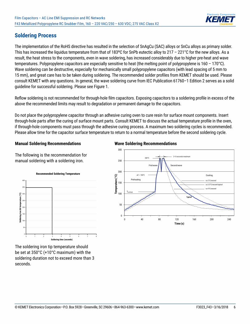
Manual Soldering Recommendations
The following is the recommendation for manual soldering with a soldering iron.
The soldering iron tip temperature should besetat350°C(+10°Cmaximum)withthesoldering duration not to exceed more than 3 seconds.
Recommended Soldering Temperature
0
50
100
150
200
250
300
350
400
0 1 2 3 4 5 6 7 8
Soldering time (seconds)
Sold
erin
g iro
n bi
t tem
pera
ture
(°C)
Soldering Process
The implementation of the RoHS directive has resulted in the selection of SnAgCu (SAC) alloys or SnCu alloys as primary solder. Thishasincreasedtheliquidustemperaturefromthatof183ºCforSnPbeutecticalloyto217–221°Cforthenewalloys.Asaresult, the heat stress to the components, even in wave soldering, has increased considerably due to higher pre-heat and wave temperatures.Polypropylenecapacitorsareespeciallysensitivetoheat(themeltingpointofpolypropyleneis160–170°C).Wave soldering can be destructive, especially for mechanically small polypropylene capacitors (with lead spacing of 5 mm to 15mm),andgreatcarehastobetakenduringsoldering.TherecommendedsolderprofilesfromKEMETshouldbeused.Pleaseconsult KEMET with any questions. In general, the wave soldering curve from IEC Publication 61760–1 Edition 2 serves as a solid guideline for successful soldering. Please see Figure 1.
Reflowsolderingisnotrecommendedforthrough-holefilmcapacitors.Exposingcapacitorstoasolderingprofileinexcessoftheabove the recommended limits may result to degradation or permanent damage to the capacitors.
Do not place the polypropylene capacitor through an adhesive curing oven to cure resin for surface mount components. Insert through-holepartsafterthecuringofsurfacemountparts.ConsultKEMETtodiscusstheactualtemperatureprofileintheoven,if through-hole components must pass through the adhesive curing process. A maximum two soldering cycles is recommended. Please allow time for the capacitor surface temperature to return to a normal temperature before the second soldering cycle.
Wave Soldering Recommendations
0
50
100
150
200
250
300
0 40 80 120 160 200 240
Tem
pera
ture
(°C)
Time (s)
ca 2°C/second
ca 3.5°C/second typical
ca 5°C/second
Cooling
2 +3 seconds maximum
115 °C maxTpreheat
∆T < 150°C
100 °C
Preheating
Typical
First wave Second wave
260°C
© KEMET Electronics Corporation • P.O. Box 5928 • Greenville, SC 29606 • 864-963-6300 • www.kemet.com F3023_F43 • 3/16/2018 7
Film Capacitors – AC Line EMI Suppression and RC NetworksF43 Metallized Polypropylene RC Snubber Film, 160 – 220 VAC/250 – 630 VDC; 275 VAC Class X2
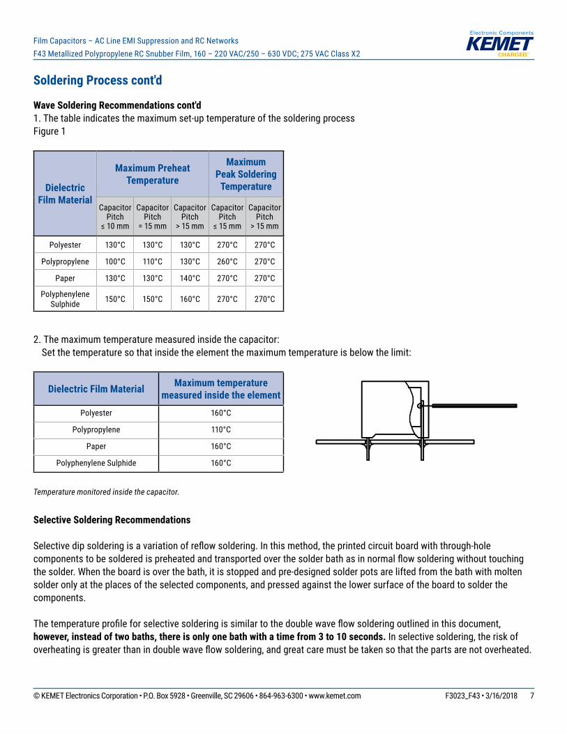
Soldering Process cont'd
Wave Soldering Recommendations cont'd1. The table indicates the maximum set-up temperature of the soldering processFigure 1
Dielectric Film Material
Maximum Preheat Temperature
Maximum Peak Soldering
Temperature
Capacitor Pitch
≤10mm
Capacitor Pitch
= 15 mm
Capacitor Pitch
> 15 mm
Capacitor Pitch
≤15mm
Capacitor Pitch
> 15 mm
Polyester 130°C 130°C 130°C 270°C 270°C
Polypropylene 100°C 110°C 130°C 260°C 270°C
Paper 130°C 130°C 140°C 270°C 270°C
Polyphenylene Sulphide 150°C 150°C 160°C 270°C 270°C
2. The maximum temperature measured inside the capacitor: Set the temperature so that inside the element the maximum temperature is below the limit:
Dielectric Film Material Maximum temperature measured inside the element
Polyester 160°C
Polypropylene 110°C
Paper 160°C
Polyphenylene Sulphide 160°C
Temperature monitored inside the capacitor.
Selective Soldering Recommendations
Selectivedipsolderingisavariationofreflowsoldering.Inthismethod,theprintedcircuitboardwiththrough-holecomponentstobesolderedispreheatedandtransportedoverthesolderbathasinnormalflowsolderingwithouttouchingthe solder. When the board is over the bath, it is stopped and pre-designed solder pots are lifted from the bath with molten solder only at the places of the selected components, and pressed against the lower surface of the board to solder the components.
Thetemperatureprofileforselectivesolderingissimilartothedoublewaveflowsolderingoutlinedinthisdocument,however, instead of two baths, there is only one bath with a time from 3 to 10 seconds. In selective soldering, the risk of overheatingisgreaterthanindoublewaveflowsoldering,andgreatcaremustbetakensothatthepartsarenotoverheated.
© KEMET Electronics Corporation • P.O. Box 5928 • Greenville, SC 29606 • 864-963-6300 • www.kemet.com F3023_F43 • 3/16/2018 8
Film Capacitors – AC Line EMI Suppression and RC NetworksF43 Metallized Polypropylene RC Snubber Film, 160 – 220 VAC/250 – 630 VDC; 275 VAC Class X2
Marking
• KEMET’s logo• Series• Capacitance• Rated resistance• Rated voltage• Capacitor class• Approval marks• IEC climatic category• Passiveflammabilityclass• Manufacturing date code
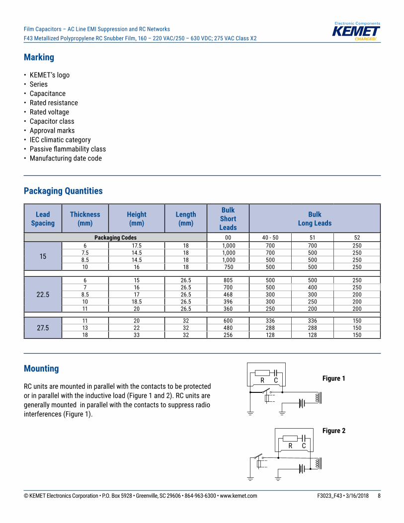
Packaging Quantities
Lead Spacing
Thickness (mm)
Height (mm)
Length (mm)
Bulk Short Leads
Bulk Long Leads
Packaging Codes 00 40 - 50 51 52
156 17.5 18 1,000 700 700 250
7.5 14.5 18 1,000 700 500 2508.5 14.5 18 1,000 500 500 25010 16 18 750 500 500 250
22.5
6 15 26.5 805 500 500 2507 16 26.5 700 500 400 250
8.5 17 26.5 468 300 300 20010 18.5 26.5 396 300 250 20011 20 26.5 360 250 200 200
27.511 20 32 600 336 336 15013 22 32 480 288 288 15018 33 32 256 128 128 150
Mounting
RC units are mounted in parallel with the contacts to be protected or in parallel with the inductive load (Figure 1 and 2). RC units are generally mounted in parallel with the contacts to suppress radio interferences (Figure 1).
R C
R C
Figure 2
Figure 1
© KEMET Electronics Corporation • P.O. Box 5928 • Greenville, SC 29606 • 864-963-6300 • www.kemet.com F3023_F43 • 3/16/2018 9
Film Capacitors – AC Line EMI Suppression and RC NetworksF43 Metallized Polypropylene RC Snubber Film, 160 – 220 VAC/250 – 630 VDC; 275 VAC Class X2
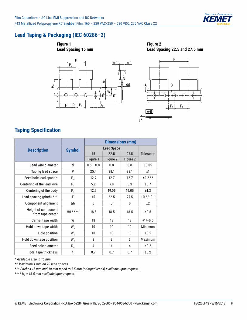
Lead Taping & Packaging (IEC 60286–2)
Taping Specification
Description Symbol
Dimensions (mm)Lead Space
Tolerance15 22.5 27.5Figure 1 Figure 2 Figure 2
Lead wire diameter d 0.6 – 0.8 0.8 0.8 ±0.05
Taping lead space P 25.4 38.1 38.1 ±1
Feed hole lead space * P0 12.7 12.7 12.7 ±0.2 **
Centering of the lead wire P1 5.2 7.8 5.3 ±0.7
Centering of the body P2 12.7 19.05 19.05 ±1.3
Lead spacing (pitch) *** F 15 22.5 27.5 +0.6/−0.1
Component alignment ∆h 0 0 0 ±2
Height of component from tape center H0 **** 18.5 18.5 18.5 ±0.5
Carrier tape width W 18 18 18 +1/−0.5
Hold down tape width W0 10 10 10 Minimum
Hole position W1 10 10 10 ±0.5
Hold down tape position W2 3 3 3 Maximum
Feed hole diameter D0 4 4 4 ±0.2
Total tape thickness t 0.7 0.7 0.7 ±0.2
* Available also in 15 mm.** Maximum 1 mm on 20 lead spaces.*** Pitches 15 mm and 10 mm taped to 7.5 mm (crimped leads) available upon request.**** H0 = 16.5 mm available upon request.
PP2
P0F
H0
W
h
P1 D0W
2
W1
W0
h
ød
P
P2P1
Figure 1Lead Spacing 15 mm
Figure 2Lead Spacing 22.5 and 27.5 mm
t
A-B
A B
© KEMET Electronics Corporation • P.O. Box 5928 • Greenville, SC 29606 • 864-963-6300 • www.kemet.com F3023_F43 • 3/16/2018 10
Film Capacitors – AC Line EMI Suppression and RC NetworksF43 Metallized Polypropylene RC Snubber Film, 160 – 220 VAC/250 – 630 VDC; 275 VAC Class X2
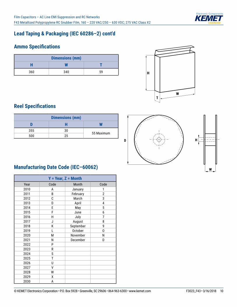
Lead Taping & Packaging (IEC 60286–2) cont'd
Ammo Specifications
Dimensions (mm)H W T
360 340 59
Reel Specifications
Dimensions (mm)D H W
355 3055 Maximum
500 25
Manufacturing Date Code (IEC–60062)
Y = Year, Z = MonthYear Code Month Code2010 A January 12011 B February 22012 C March 32013 D April 42014 E May 52015 F June 62016 H July 72017 J August 82018 K September 92019 L October O2020 M November N2021 N December D2022 P2023 R2024 S2025 T2026 U2027 V2028 W2029 X2030 A
D
W
H
H
TW

© KEMET Electronics Corporation • P.O. Box 5928 • Greenville, SC 29606 • 864-963-6300 • www.kemet.com F3023_F43 • 3/16/2018 11
Film Capacitors – AC Line EMI Suppression and RC NetworksF43 Metallized Polypropylene RC Snubber Film, 160 – 220 VAC/250 – 630 VDC; 275 VAC Class X2
KEMET Electronics Corporation Sales Offi ces
Foracompletelistofourglobalsalesoffices,pleasevisitwww.kemet.com/sales.
DisclaimerAllproductspecifications,statements,informationanddata(collectively,the“Information”)inthisdatasheetaresubjecttochange.Thecustomerisresponsibleforchecking and verifying the extent to which the Information contained in this publication is applicable to an order at the time the order is placed.
All Information given herein is believed to be accurate and reliable, but it is presented without guarantee, warranty, or responsibility of any kind, expressed or implied.
StatementsofsuitabilityforcertainapplicationsarebasedonKEMETElectronicsCorporation’s(“KEMET”)knowledgeoftypicaloperatingconditionsforsuchapplications,butarenotintendedtoconstitute–andKEMETspecificallydisclaims–anywarrantyconcerningsuitabilityforaspecificcustomerapplicationoruse.The Information is intended for use only by customers who have the requisite experience and capability to determine the correct products for their application. Any technical advice inferred from this Information or otherwise provided by KEMET with reference to the use of KEMET’s products is given gratis, and KEMET assumes no obligation or liability for the advice given or results obtained.
Although KEMET designs and manufactures its products to the most stringent quality and safety standards, given the current state of the art, isolated component failures may still occur. Accordingly, customer applications which require a high degree of reliability or safety should employ suitable designs or other safeguards (suchasinstallationofprotectivecircuitryorredundancies)inordertoensurethatthefailureofanelectricalcomponentdoesnotresultinariskofpersonalinjuryorproperty damage.
Although all product–related warnings, cautions and notes must be observed, the customer should not assume that all safety measures are indicted or that other measures may not be required.
KEMET is a registered trademark of KEMET Electronics Corporation.