Embed Size (px)
Citation preview
9991035 Rev. J
A.C. MODULAR GENERATOR SYSTEM
OWNERS MANUAL
MODEL#: HR-6.2, HR-8, HR-10 and HR-110
Smart Power Systems® A. C. MODULAR GENERATOR SYSTEM
Page 1 of 51
Table of Contents
Section Page
Disclaimer .......................................................................................................................... 5
Description of Product ...................................................................................................... 6
System Specifications ...................................................................................................... 9
Pre-Installation Guide ..................................................................................................... 11
Installation Guide ............................................................................................................ 17
Hose Installation Guidelines .......................................................................................... 21
Operation ......................................................................................................................... 29
Special Operating Instructions ...................................................................................... 35
Maintenance Instructions ............................................................................................... 36
Troubleshooting Guide ................................................................................................... 39
SPS Model Matrix ............................................................................................................ 47
Pump Adjustment............................................................................................................ 48
Doc. 9991035 Rev. J
ECO # 16219

Smart Power Systems® A. C. MODULAR GENERATOR SYSTEM
Page 2 of 51
WARNING:
Do not install or operate the A.C. modular generator system without reading this entire manual.
The A.C. modular generator system will generate enough voltage to produce a fatal electrical shock. Do not perform any wiring installations or modifications while the system is operating. Never touch any live connections while the system is operating. Never operate the system with the generator wiring enclosure open. Install and secure cover before operating.
The installation of the Smart Power A.C. modular generator system is to be done in accordance with applicable sections in the National Fire Protection Association’s document NFPA 1901, National Electrical Code®, and/or other applicable, recognized electrical codes and by a certified electrician.
Never directly expose the generator to any liquids, especially water, oil, or solvents. Electrical shock, fire and/or damage to the generator can occur and will void the system’s warranty.
Smart Power hydraulic generators, as well as all generators, must be sufficiently protected from the environment to prevent damage to the stator. Smart Power stators go through a very important double-dip coating process prior to generator assembly, however, exposure to direct water sprays can cause the stator to electrically short. Generator damage and electrical shock can occur. Caution should be taken during truck pressure washing, since water damage to the generator can occur if directly sprayed with high water pressure. Though Smart Power Systems® (SPS) generators are enclosed as much as possible, direct spray through the cooler, fan or open lid can still cause such damage. Excessive road spray/salt can also cause an electrical short of the stator in the generator and can also shorten the generator’s operating life. To prevent this type of damage, do not mount the system where it will be exposed to road spray. Evidence of water damage, road spray/salt infiltration, and improper mounting will void the generator warranty. Avoid physical contact with any of the components of the A.C. modular generator system during its operation or immediately after its use. The components of this system will get hot enough to cause burns and could ignite combustible materials.
Do not mount or locate anything inside of the framework. System overheating could result and void the system’s warranty.
Smart Power Systems® A. C. MODULAR GENERATOR SYSTEM
Page 3 of 51
Never operate the system with leaks of any type. Clean up any hydraulic fluid that is spilled or has leaked out of the system. Hydraulic fluid is combustible, and ignition may occur.
With the exception of instructions within this manual, never modify or remove any of the components within the tray assembly.
Never modify or remove any of the components within the pump or the controls mounted to the pump. This includes all fittings and tubing that are originally provided with the A.C. modular generator system.
Never make any adjustments to the pump other than for flow control. If it appears the pump needs to be adjusted, contact Smart Power Systems® at (231) 832-5525 before proceeding. Damage to the generator from improper pump adjustment will void the system’s warranty.
Never attempt any adjustments or repairs to the A.C. modular generator system (other than pump flow control) while the vehicle engine is running and the PTO is engaged.
Never operate the system with the hydraulic fluid exceeding 195F. Above this temperature, hydraulic fluid can rapidly oxidize and deteriorate causing generator
performance problems. Operating the system while the hydraulic fluid is above 195F will void the system’s warranty.
Hydraulic fluid is combustible and toxic. In the event of human contact with hydraulic fluid, generously flush body part (eyes, skin, etc.) with running water. Avoid inhalation of any oil mist or vapor. Do not ingest hydraulic fluid. In case of fire, use foam, dry chemical or carbon dioxide to extinguish flame.
Do not exceed the wattage rating of the generator. The generator may be permanently damaged and the generator and hydraulic components may reach temperatures that could cause severe burns upon human contact with the components. Operating the generator system at wattages above the system’s rating will void the system’s warranty.
Disengage the system immediately if a hydraulic fluid leak is detected. Operation of the A.C. modular generator system with low fluid level will result in permanent damage to the hydraulic components in the system and will void the system’s warranty.
Do not tamper with the hydraulic fluid level sensor.
Never attempt to operate the system without hydraulic fluid. Always maintain a fluid level between ½ to ¾ full in the sight plug. When installing the system, fill the pump case with a minimum of 1 pint of hydraulic fluid (Dexron III) before engaging the system. Failing to do so will void the system’s warranty.
Operating the A.C. modular generator system in the presence of flammable vapors may result in an explosion.
Smart Power Systems® A. C. MODULAR GENERATOR SYSTEM
Page 4 of 51
Use only hoses that meet or exceed the minimum requirements specified in this manual. A ruptured hose can cause personal injury and/or damage to the generator system.
Do not operate the system under electrical load with air in the hydraulic fluid (the system will make a growling sound). Do not allow anything to contact the hydraulic hoses that will cause a kink, pinch or chaffing. The A.C. modular hydraulic system generates hydraulic pressures approaching 3600 psi. A ruptured hose may result from abrasion, discharging hot, high-pressure hydraulic fluid, which can cause serious personal injury, fire, and/or damage to the system.
Never remove the guards on the generator to expose the rotating fan or motor coupling. Personal injury will result if fingers, hair or loose clothing come in contact with rotating components.

Smart Power Systems® A. C. MODULAR GENERATOR SYSTEM
Page 5 of 51
Disclaimer
Although SPS has taken all reasonable care to ensure that the information contained in this installation manual (including without limitation, references, databases, resources, specifications, illustrations and instructions) was accurate in all material respects at the time of publication, SPS PROVIDES NO ASSURANCE, REPRESENTATION, WARRANTY OR GUARANTEE, expressed or implied (including third party liability), with regard to this manual, including without limiting the generality of the foregoing, with regard to its accuracy, reliability or completeness. The entire information contained in this installation manual is provided by SPS “AS IS” and without warranty of any kind, express or implied, including (but not limited to) any implied warranties or merchantability, fitness for any particular purpose, or non-infringement. Accordingly, by using the SPS unit and this information, you agree that, to the greatest extent permitted by law, SPS (including, without limitation, its subsidiaries, affiliates, agents, officers, directors, employees and insurers) is not and will not be liable for losses or damages resulting from this installation manual, its use, any information contained therein or the installation of the SPS unit. This installation manual contains references to certain database and resources. As SPS has no control over these database and resources, you acknowledge and agree that SPS is not responsible or liable for any content, advertising, products, information or other materials on or available from such database or resources. You further acknowledge and agree that SPS shall not be responsible or liable, directly or indirectly, for any damage or loss caused or alleged to be caused by or in connection with use of or reliance on any such content, information goods or services available on or through any such database or resources. All product illustrations and specifications are based upon current information at the time of publication. Although descriptions are believed correct, complete accuracy cannot be guaranteed. SPS reserves the right to make changes of any kind at any time, without notice or obligation, in the information contained on this installation manual. All data and information of any kind are subject to change without notice and SPS assumes no obligation to update or correct information in this manual. As some states do not allow the exclusion or limitation of liability for consequential or incidental damages, the limitation contained herein may not apply to you. In such states, SPS’ liability is limited to the greatest extent liability limitation is permitted by applicable law.
Smart Power Systems® A. C. MODULAR GENERATOR SYSTEM
Page 6 of 51
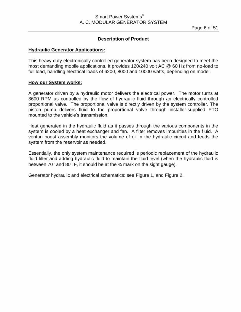
Description of Product Hydraulic Generator Applications: This heavy-duty electronically controlled generator system has been designed to meet the most demanding mobile applications. It provides 120/240 volt AC @ 60 Hz from no-load to full load, handling electrical loads of 6200, 8000 and 10000 watts, depending on model. How our System works: A generator driven by a hydraulic motor delivers the electrical power. The motor turns at 3600 RPM as controlled by the flow of hydraulic fluid through an electrically controlled proportional valve. The proportional valve is directly driven by the system controller. The piston pump delivers fluid to the proportional valve through installer-supplied PTO mounted to the vehicle’s transmission. Heat generated in the hydraulic fluid as it passes through the various components in the system is cooled by a heat exchanger and fan. A filter removes impurities in the fluid. A venturi boost assembly monitors the volume of oil in the hydraulic circuit and feeds the system from the reservoir as needed. Essentially, the only system maintenance required is periodic replacement of the hydraulic fluid filter and adding hydraulic fluid to maintain the fluid level (when the hydraulic fluid is
between 70 and 80 F, it should be at the ¾ mark on the sight gauge). Generator hydraulic and electrical schematics: see Figure 1, and Figure 2.
Smart Power Systems® A. C. MODULAR GENERATOR SYSTEM
Page 7 of 51
CASE DRAINx
y
RESERVOIR
PUMP
PROPORTIONAL
VALVE
CASE DRAIN
MOTOR
COOLER
FILTER
BOOST BLOCK
VENTURI BOOST
CHECK
VALVE
IN
BP
REG
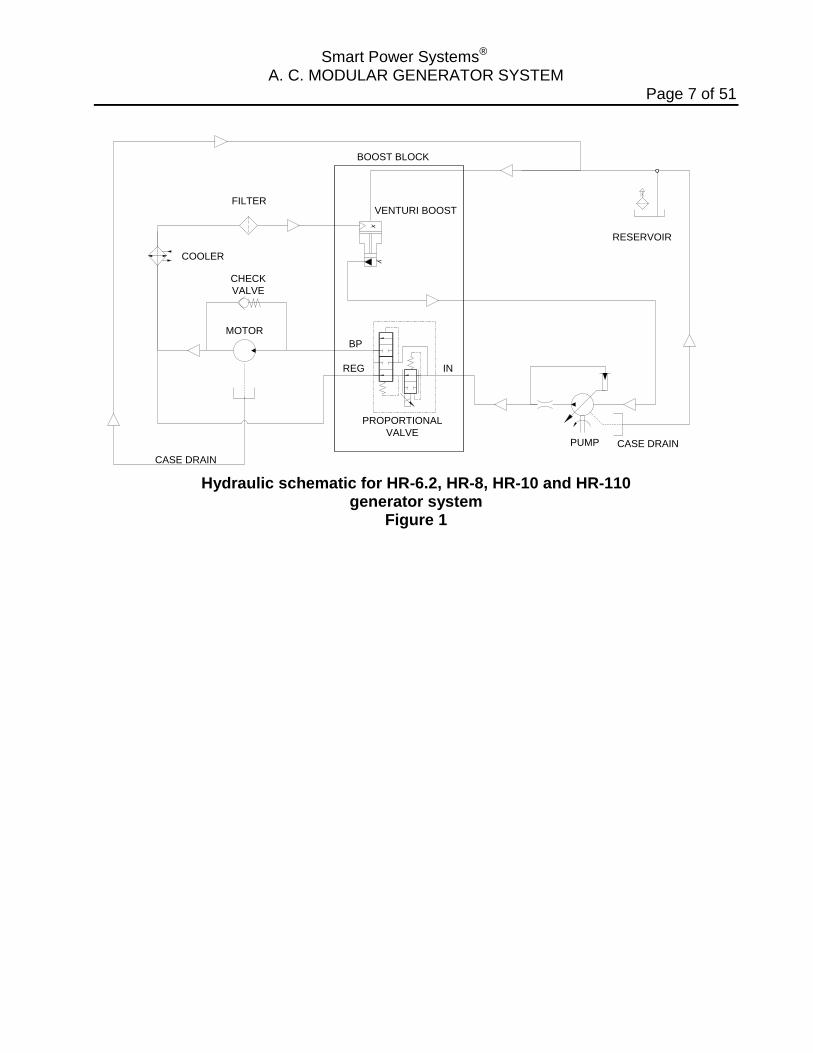
Hydraulic schematic for HR-6.2, HR-8, HR-10 and HR-110
generator system Figure 1
Smart Power Systems® A. C. MODULAR GENERATOR SYSTEM
Page 8 of 51
+ -
Fan
Mo
tor
22
11
221
1
3
2 3
2
11
BU
ZZER
432
432
11
432
432
11
IND
ICA
TOR
BU
LB
VEH
ICLE
+12V
SU
PP
LY
VEH
ICLE
+12V
SU
PP
LY
VEH
ICLE
+12V
SU
PP
LY
NO
T P
RO
VID
ED
GR
N
BLK
PIN
K
BLU
YELL
PU
RP
/YELL
GR
N/W
HT
BLK
/WH
TP
UR
P
YELL
OW
BLK
OR
G
OR
G
GR
Y
BR
N/W
HT
RIN
G O
R S
PLI
CE
RED
VEH
ICLE
GN
D
VEH
ICLE
+12V
SU
PP
LY
GR
N/W
HT
BLK
/WH
TP
UR
P
YELL
OW
COMMAND & CONTROL
CENTER
P/N 1500047
ASM
, O
IL T
EM
P.
SEN
SO
R
P/N
3310736
PR
OP
. C
ON
TRO
L
VA
LVE
P/N
8594452
PR
ESSU
RE S
WIT
CH
P/N
8594019
SY
STE
M C
ON
TRO
LLER
P/N
8505035 (
HR
-6.2
, H
R-8
, H
R-1
0, H
R-1
10)
GEN
ER
ATO
R
OU
TPU
T
GEN
ER
ATO
R
OU
TPU
T
WH
T/BLU
WH
T/R
ED
WH
T
BLK
GR
N
WIN
DIN
G A
WIN
DIN
G B
GEN
ER
ATO
R
OU
TPU
T
BLU
/WH
T
OR
G/W
HT
RED
GEN
ER
ATO
R
OU
TPU
T
CU
RR
EN
T TR
AN
S.
P/N
1500035
CO
NN
4
CO
NN
6C
ON
N 1
CO
NN
5
CO
NN
2
SP
S D
ISP
LAY
WIR
E H
AR
NESS
P/N
3722004
PU
RP
/WH
T
RED
/WH
T
CO
NN
3 11 2
2221
1
GEN
ER
ATO
R
CU
RR
EN
T TR
AN
S.
P/N
1500035
CH
ASSIS
1 2 3 4
ASM
, O
IL L
EV
EL
SEN
SO
R
P/N
3320106
11 2
2
BLK
/YELL
YELL
OW
CO
NN
5
221
1
REM
OTE
EN
B. SW
(M
UST
BE
A M
OM
EN
TAR
Y S
WIT
CH
)
WA
RN
ING
:
12 V
OLT
S D
C M
UST
BE D
IREC
TLY
APPLI
ED
TO
TH
E G
EN
ER
ATO
R S
YSTE
M
CO
NTR
OLL
ER
WH
EN
EV
ER
TH
E H
YD
RA
ULI
C P
UM
P IS E
NG
AG
ED
.
FAIL
UR
E T
O D
O S
O M
AY
CA
USE E
XC
ESSIV
E F
LUID
TEM
PER
ATU
RE,
DA
MA
GIN
G T
HE S
YSTE
M C
OM
PO
NEN
TS A
ND
WIL
L V
OID
TH
E W
AR
RA
NTY
.
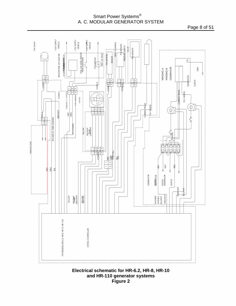
Electrical schematic for HR-6.2, HR-8, HR-10
and HR-110 generator systems Figure 2

Smart Power Systems® A. C. MODULAR GENERATOR SYSTEM
Page 9 of 51
System Specifications MODEL OF GENERATOR
HR-6.2 HR-8 HR-10 HR-110
Generator Type Speed Frequency Voltage
Amperage
Output Power
AC Inductive 3600 RPM 60 Hz 240 VAC or 120/240 VAC 52A @ 120 VAC or 26A @ 240 VAC 6.2 KW continuous 7.5 KW peak
AC Inductive 3600 RPM 60 Hz 240 VAC or 120/240 VAC 67A @ 120 VAC or 34A @ 240 VAC 8 KW continuous 9 KW peak
AC Inductive 3600 RPM 60 Hz 240 VAC or 120/240 VAC 84A @ 120 VAC or 42A @ 240 VAC 10 KW continuous 12 KW peak
AC Inductive 3600 RPM 60 Hz 240 VAC or 120/240 VAC 84A @ 120 VAC or 42A @ 240 VAC 10 KW continuous 12 KW peak
Hydraulic Motor Maximum Speed Motor Shaft Size Port Size
Gear Type, 8cc 4000 RPM 0.626 inches 9 tooth spline 7/8” – 14 SAE 7/8” – 14 SAE
Gear Type, 8cc 4000 RPM 0.626 inches 9 tooth spline 7/8” – 14 SAE 7/8” – 14 SAE
Gear Type, 11cc
4000 RPM 0.626 inches 9 tooth spline 7/8” – 14 SAE 7/8” – 14 SAE
Gear Type, 11cc
4000 RPM 0.626 inches 9 tooth spline 7/8” – 14 SAE 7/8” – 14 SAE
Hydraulic Pump Operating Speed Standard Shaft
Optional Shaft
Mounting Flange Displacement Continuous Pressure (Max) Peak Pressure Standard Rotation
Dry Weight
Piston w/pressure compensated control 880-3000 RPM continuous duty SAE B 7/8”-13 Tooth Spline SAE 1” parallel with key SAE B-B 1” 15T Spline SAE B-2 bolt mount 45cc per revolution 3500 psi (250 bar) 4600 psi (315 bar) Engine right-hand rotation (opposite engine rotation available upon request) 46 lbs
Piston w/pressure compensated control 880-3000 RPM continuous duty SAE B 7/8”-13 Tooth Spline SAE 1” parallel with key SAE B-B 1” 15T Spline SAE B-2 bolt mount 45cc per revolution 3500 psi (250 bar) 4600 psi (315 bar) Engine right-hand rotation (opposite engine rotation available upon request) 46 lbs
Piston w/pressure compensated control 1100-3000 RPM continuous duty SAE B 7/8”-13 Tooth Spline SAE 1” parallel with key SAE B-B 1” 15T Spline SAE B-2 bolt mount 45cc per revolution 3500 psi (250 bar) 4600 psi (315 bar) Engine right-hand rotation (opposite engine rotation available upon request) 46 lbs
Piston w/pressure compensated control 850-2700 RPM continuous duty SAE B-B 1” 15 Tooth Spline SAE 1¼” parallel with key SAE B-2 bolt mount 60cc per revolution 3500 psi (250 bar) 4600 psi (315 bar) Engine right-hand rotation (opposite engine rotation available upon request) 51 lbs
Table 1
Smart Power Systems® A. C. MODULAR GENERATOR SYSTEM
Page 10 of 51
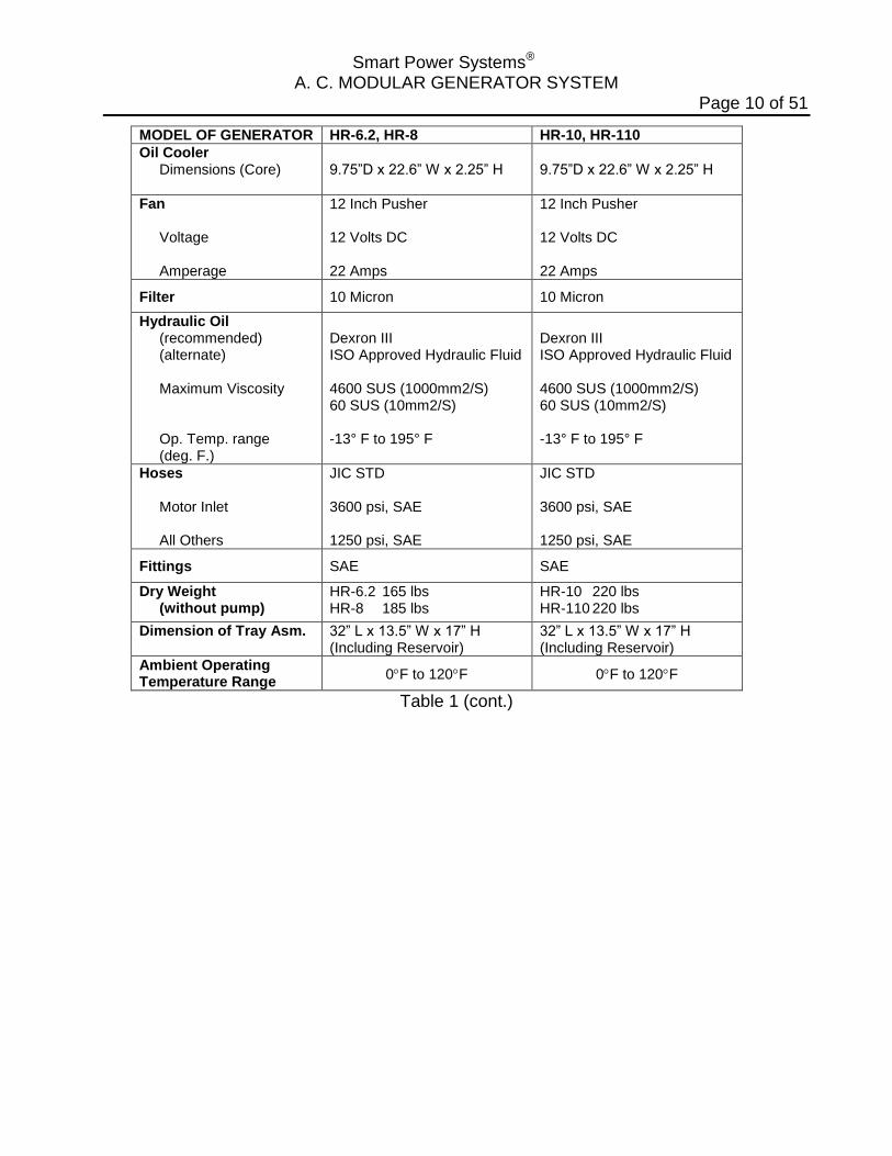
MODEL OF GENERATOR HR-6.2, HR-8 HR-10, HR-110
Oil Cooler Dimensions (Core)
9.75”D x 22.6” W x 2.25” H
9.75”D x 22.6” W x 2.25” H
Fan Voltage Amperage
12 Inch Pusher 12 Volts DC 22 Amps
12 Inch Pusher 12 Volts DC 22 Amps
Filter 10 Micron 10 Micron
Hydraulic Oil (recommended) (alternate) Maximum Viscosity Op. Temp. range (deg. F.)
Dexron III ISO Approved Hydraulic Fluid 4600 SUS (1000mm2/S) 60 SUS (10mm2/S) -13° F to 195° F
Dexron III ISO Approved Hydraulic Fluid 4600 SUS (1000mm2/S) 60 SUS (10mm2/S) -13° F to 195° F
Hoses Motor Inlet All Others
JIC STD 3600 psi, SAE 1250 psi, SAE
JIC STD 3600 psi, SAE 1250 psi, SAE
Fittings SAE SAE
Dry Weight (without pump)
HR-6.2 165 lbs HR-8 185 lbs
HR-10 220 lbs HR-110 220 lbs
Dimension of Tray Asm. 32” L x 13.5” W x 17” H (Including Reservoir)
32” L x 13.5” W x 17” H (Including Reservoir)
Ambient Operating Temperature Range
0F to 120F 0F to 120F
Table 1 (cont.)
Smart Power Systems® A. C. MODULAR GENERATOR SYSTEM
Page 11 of 51
Pre-Installation Guide Pre-Installation Check List 1. Verify that the Power Take Off (PTO) and the pump rotations match. To identify the pump rotation, check the pump part number found on the metal tag
attached to side of the pump. A right hand rotating pump (the standard pump offered by Smart Power® Systems), will have the letter “R” in its part number.
Example: A10VO (45 or 60) DFR-1/52 R PUC. A left hand rotating pump will have the letter “L” in its part number. Example: A10VO (45 or 60) DRF-1/52 L PUC. Depending on genset model, a 45cc or 60cc pump is supplied. To determine the
PTO rotation, check the PTO manufacturer’s specification or observe the PTO when it is engaged with the vehicle’s engine running.
A right hand rotating pump requires a PTO that turns counter-clockwise when looking
at the free end of the PTO shaft. A left hand rotating pump requires a PTO that turns clockwise when looking at the free end of the PTO shaft.
WARNING:
Operating the pump with reverse rotation will damage the pump and void the system’s warranty. 2. Verify that the PTO ratio is properly sized to provide adequate speed to the
hydraulic pump during normal operation of the generator system. The PTO speed must be between in the range specified in Table 1 for your model generator.
Example: For an HR-8 System that is to operate at 650 RPM engine speed: PTO Ratio = 880 RPM ÷ 650 RPM = 1.35 or 135% (or higher)
WARNING: Never exceed the maximum pump shaft speed. Pump failure or premature pump wear will result. Doing so will void the system’s warranty.
Smart Power Systems® A. C. MODULAR GENERATOR SYSTEM
Page 12 of 51
3. Verify the combined weight of the pump and hoses filled with hydraulic fluid do not exceed the PTO manufacturer’s weight restriction. If the pump weight does exceed this restriction, the installer has two options: A) a bracket to support the pump can be implemented, or B) the pump can be mounted to the vehicle chassis, connected to the PTO with a drive shaft.
4. Verify that the pump shaft will mount to the PTO. Pumps supplied by Smart Power
Systems® have an SAE B 2 bolt flange. The standard pumps supplied by Smart Power Systems® have either a SAE B 7/8” 13 tooth spline for Models HR-6.2, HR-8 and HR-10; OR a SAE B-B 1” 15 tooth spline on the HR-110 model.
Upon special order, a 1” keyed shaft or 1” 15 tooth spline is available on Models
HR-6, HR-8 and HR-10. A 1 ¼” keyed shaft is available on the HR-110 Model. Check the PTO manufacturer’s specification to verify that the pump supplied with the system will mount to the PTO installed on the vehicle.
Note: In some cases it may be necessary to mount the pump remote from the PTO
and drive it with a drive shaft. Contact the PTO manufacturer for information on the proper mounting configuration under these conditions.
WARNING:
The installer must provide guarding to prevent damage to the pump seals from road debris if the pump is remotely located. Also, properly sized and installed vibration isolators must be used if the pump is mounted to the chassis. Failure to do either will void the system’s warranty. Never use an unbalanced drive shaft to drive a remotely located pump. An unbalanced drive shaft will cause premature wear of the pump and will void the system’s warranty. Do not approach a running A.C. modular generator when wearing long, loose items such as hair, jewelry, ties, clothing, etc. Direct contact with a rotating drive shaft can cause serious personal injury and/or damage to the system. 5. Obtain the following hoses of the necessary length for the installation:
a) Pump inlet hose: 1” SAE 100R1AT-16 hose (use Parker hose ends P/N 10643-16-16). Note: Maximum hose length is 20’.
b) Pump outlet hose: 1/2” SAE 100R9AT-8 rated to 4000 PSI (use Parker hose ends, part number 10643-8-8). Note: Maximum hose length is 20’.
c) Pump case drain hose: 5/8” SAE 100R1AT-10 (use Parker hose ends, part number 10643-10-10). Note: Maximum hose length is 20’.
Smart Power Systems® A. C. MODULAR GENERATOR SYSTEM
Page 13 of 51
WARNING:
Do not install hose ends until proper hose length has been determined. Never install a hose in a location where it will rub against another surface or abrasive member. Do not position hoses with tight bend radii. Consult the hose manufacturer’s installation guidelines. Tight bends may kink and cause serious damage to the system and will void the system’s warranty. Use caution when tightening the hose ends to prevent the hose from becoming twisted. Never install a 90° fitting at the pump inlet or outlet. Avoid the use of flow restricting fittings. Do not form loops in the hose that may collect air or kink. Run hoses as straight as possible (but not taut) between connections. Do not exceed hose lengths of 20 feet. 6. SPS models HR-6.2, HR-8, HR-10 and HR-110 can be mounted on top of a
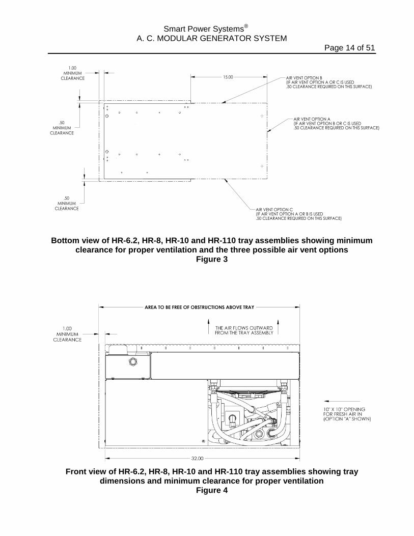
vehicle, in the open, without requiring any additional coverings. Reference Figure 3, Figure 4 and Figure 5 for the minimum clearances around the perimeter of the generator tray assembly. Also, do not position any obstructions directly in front of the system’s oil cooler. If the system cannot be installed without maintaining the minimum clearances as indicated, or if you have any questions relative to the installation of these systems, contact Smart Power Systems® at (231) 832-5525.
Smart Power Systems® A. C. MODULAR GENERATOR SYSTEM
Page 14 of 51
MINIMUM
1.00
CLEARANCE
CLEARANCEMINIMUM
.50
.50
MINIMUMCLEARANCE
15.00
AIR VENT OPTION A(IF AIR VENT OPTION B OR C IS USED.50 CLEARANCE REQUIRED ON THIS SURFACE)
AIR VENT OPTION B(IF AIR VENT OPTION A OR C IS USED.50 CLEARANCE REQUIRED ON THIS SURFACE)
AIR VENT OPTION C(IF AIR VENT OPTION A OR B IS USED.50 CLEARANCE REQUIRED ON THIS SURFACE)
Bottom view of HR-6.2, HR-8, HR-10 and HR-110 tray assemblies showing minimum
clearance for proper ventilation and the three possible air vent options Figure 3
Front view of HR-6.2, HR-8, HR-10 and HR-110 tray assemblies showing tray
dimensions and minimum clearance for proper ventilation Figure 4
Smart Power Systems® A. C. MODULAR GENERATOR SYSTEM
Page 15 of 51
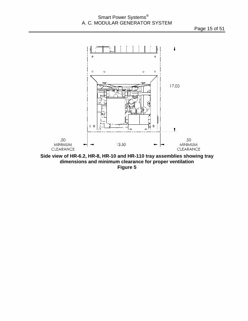
Side view of HR-6.2, HR-8, HR-10 and HR-110 tray assemblies showing tray
dimensions and minimum clearance for proper ventilation Figure 5
Smart Power Systems® A. C. MODULAR GENERATOR SYSTEM
Page 16 of 51
WARNING: Do not mount the hydraulic pump or tray assembly in any location that is not well ventilated. External heat sources elevating the hydraulic fluid and/or the generator temperature will result in premature wear and degraded system performance and void the system’s warranty. 7. The tray assembly must be mounted in a position that is higher than the pump. If
the pump inlet hose is 10’ in length or less, the tray and reservoir assemblies must be a minimum of 12” higher than the pump. If the pump inlet hose is longer than 10’, elevate the tray and reservoir assemblies an additional 12” for every additional 10’ of pump inlet hose length. See below for examples of minimum tray assembly elevations above the pump:
Pump inlet hose length Minimum tray and reservoir elevation
(above pump) 0 – 10 ft. 12 inches 15 ft. 18 inches 20 ft. 24 inches
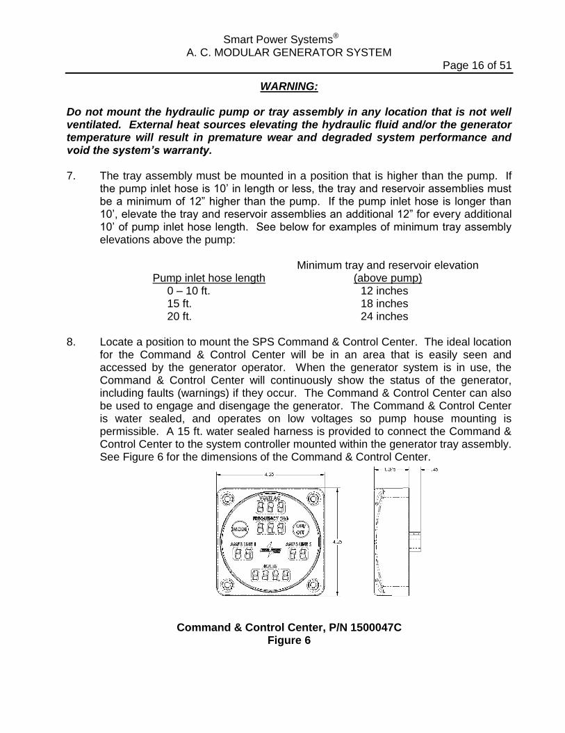
8. Locate a position to mount the SPS Command & Control Center. The ideal location
for the Command & Control Center will be in an area that is easily seen and accessed by the generator operator. When the generator system is in use, the Command & Control Center will continuously show the status of the generator, including faults (warnings) if they occur. The Command & Control Center can also be used to engage and disengage the generator. The Command & Control Center is water sealed, and operates on low voltages so pump house mounting is permissible. A 15 ft. water sealed harness is provided to connect the Command & Control Center to the system controller mounted within the generator tray assembly. See Figure 6 for the dimensions of the Command & Control Center.
Command & Control Center, P/N 1500047C Figure 6

Smart Power Systems® A. C. MODULAR GENERATOR SYSTEM
Page 17 of 51
Installation Guide 1. Mount the pump securely to the Power Take-Off (PTO). This may require attaching
a mounting bracket to the PTO housing prior to mounting the pump.
WARNING: Always mount the hydraulic pump in a position with the pump controls up. Mounting the pump in any other orientation will not allow hydraulic fluid in the pump to reach the correct level before starting, causing premature wear of the pump, thus voiding the system’s warranty. The pump and undercarriage components will corrode if they are left unprotected. It is advisable to paint them before completing the installation. 2. Locate and bore mounting holes for generator tray assembly as shown in Figure 7.
Maintain minimum clearances as indicated in Figure 3, Figure 4 and Figure 5.
Hole pattern for mounting HR-6.2, HR-8, HR-10 and HR-110 tray assemblies
Figure 7
Smart Power Systems® A. C. MODULAR GENERATOR SYSTEM
Page 18 of 51
3. Mount the tray assembly as high as possible within the structure of the vehicle. The ideal location for the generator is at the top of the truck in the dunnage area. The manufacturer must also take sufficient precautions to ensure that the generator is not mounted in the path of the deck gun/water cannon.
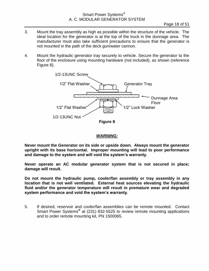
4. Mount the hydraulic generator tray securely to vehicle. Secure the generator to the
floor of the enclosure using mounting hardware (not included), as shown (reference Figure 8).
1/2-13UNC Screw 1/2” Flat Washer Generator Tray Dunnage Area Floor 1/2” Flat Washer 1/2” Lock Washer 1/2-13UNC Nut
Figure 8
WARNING: Never mount the Generator on its side or upside down. Always mount the generator upright with its base horizontal. Improper mounting will lead to poor performance and damage to the system and will void the system’s warranty. Never operate an AC modular generator system that is not secured in place; damage will result. Do not mount the hydraulic pump, cooler/fan assembly or tray assembly in any location that is not well ventilated. External heat sources elevating the hydraulic fluid and/or the generator temperature will result in premature wear and degraded system performance and void the system’s warranty. 5. If desired, reservoir and cooler/fan assemblies can be remote mounted. Contact
Smart Power Systems® at (231) 832-5525 to review remote mounting applications and to order remote mounting kit, PN 1500065.
Smart Power Systems® A. C. MODULAR GENERATOR SYSTEM
Page 19 of 51
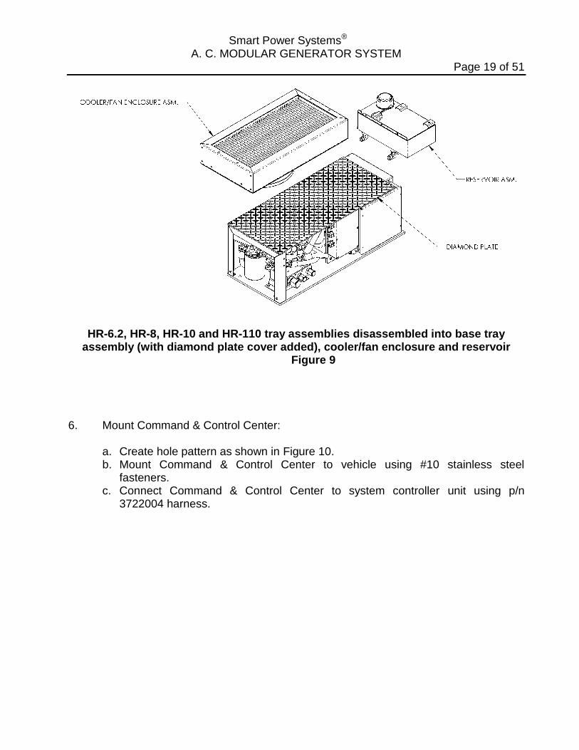
HR-6.2, HR-8, HR-10 and HR-110 tray assemblies disassembled into base tray assembly (with diamond plate cover added), cooler/fan enclosure and reservoir
Figure 9
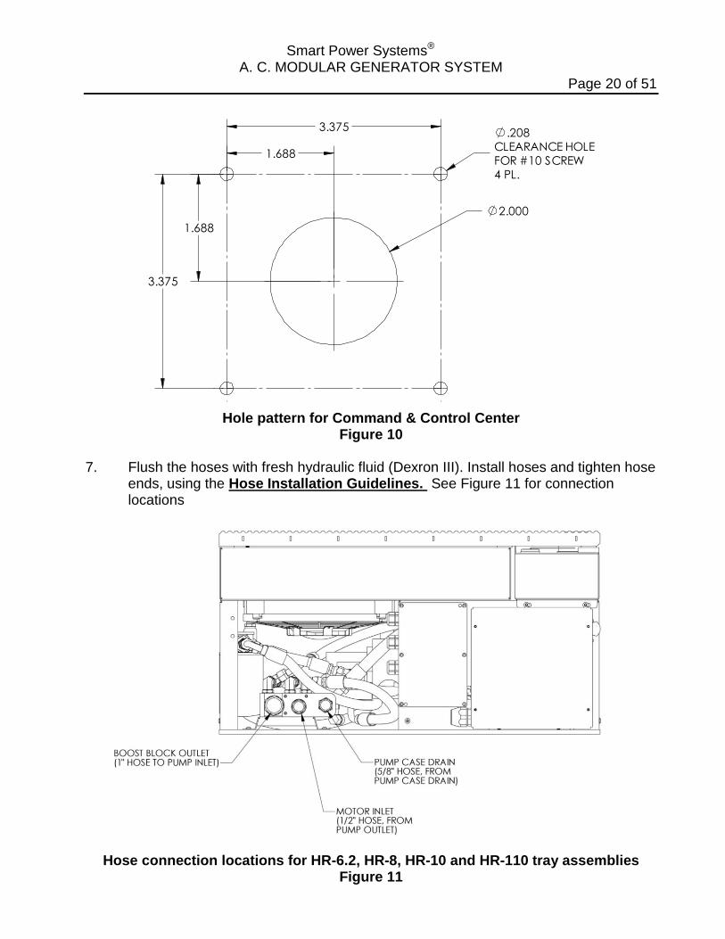
6. Mount Command & Control Center:
a. Create hole pattern as shown in Figure 10. b. Mount Command & Control Center to vehicle using #10 stainless steel
fasteners. c. Connect Command & Control Center to system controller unit using p/n
3722004 harness.
Smart Power Systems® A. C. MODULAR GENERATOR SYSTEM
Page 20 of 51
.208CLEARANCE HOLEFOR #10 SCREW4 PL.
2.000
3.375
3.375
1.688
1.688
Hole pattern for Command & Control Center
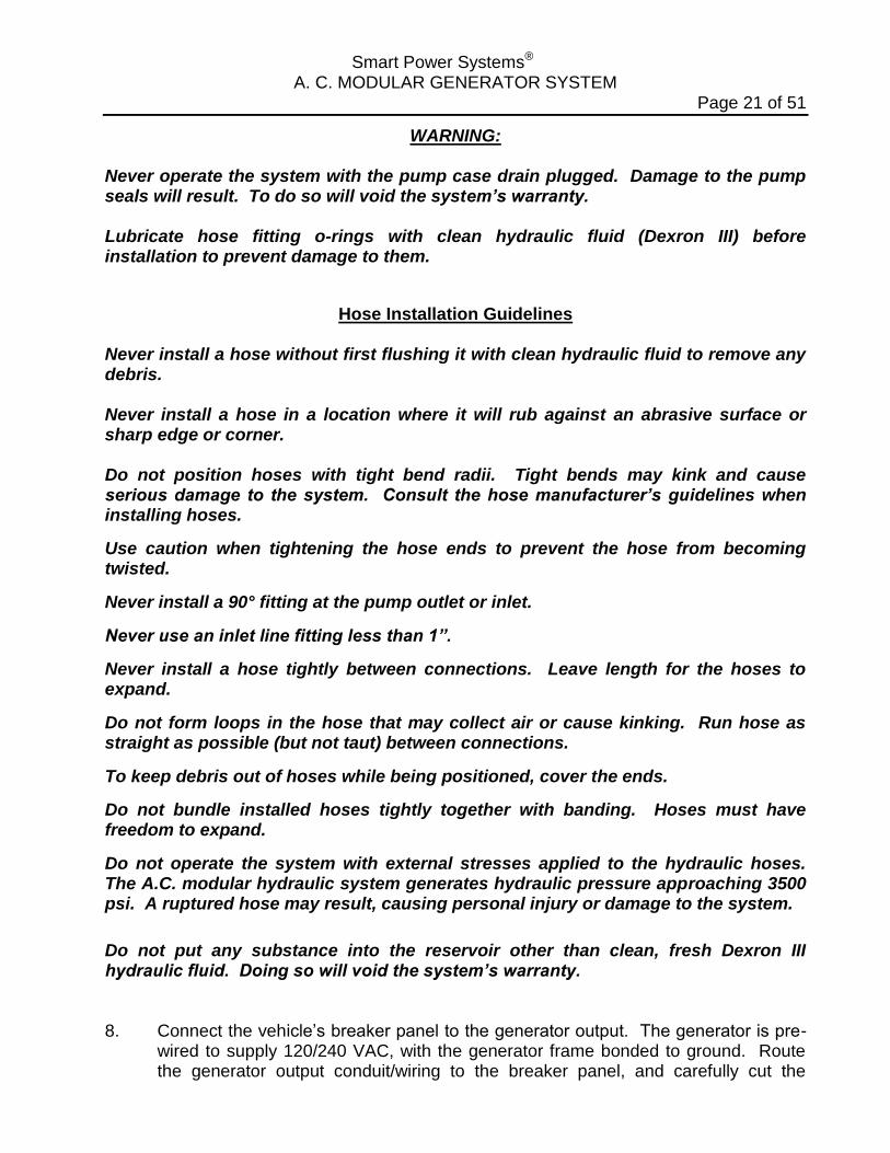
Figure 10 7. Flush the hoses with fresh hydraulic fluid (Dexron III). Install hoses and tighten hose
ends, using the Hose Installation Guidelines. See Figure 11 for connection locations
Hose connection locations for HR-6.2, HR-8, HR-10 and HR-110 tray assemblies
Figure 11
Smart Power Systems® A. C. MODULAR GENERATOR SYSTEM
Page 21 of 51
WARNING: Never operate the system with the pump case drain plugged. Damage to the pump seals will result. To do so will void the system’s warranty. Lubricate hose fitting o-rings with clean hydraulic fluid (Dexron III) before installation to prevent damage to them.
Hose Installation Guidelines Never install a hose without first flushing it with clean hydraulic fluid to remove any debris. Never install a hose in a location where it will rub against an abrasive surface or sharp edge or corner. Do not position hoses with tight bend radii. Tight bends may kink and cause serious damage to the system. Consult the hose manufacturer’s guidelines when installing hoses.
Use caution when tightening the hose ends to prevent the hose from becoming twisted.
Never install a 90° fitting at the pump outlet or inlet.
Never use an inlet line fitting less than 1”.
Never install a hose tightly between connections. Leave length for the hoses to expand.
Do not form loops in the hose that may collect air or cause kinking. Run hose as straight as possible (but not taut) between connections.
To keep debris out of hoses while being positioned, cover the ends.
Do not bundle installed hoses tightly together with banding. Hoses must have freedom to expand.
Do not operate the system with external stresses applied to the hydraulic hoses. The A.C. modular hydraulic system generates hydraulic pressure approaching 3500 psi. A ruptured hose may result, causing personal injury or damage to the system.
Do not put any substance into the reservoir other than clean, fresh Dexron III hydraulic fluid. Doing so will void the system’s warranty. 8. Connect the vehicle’s breaker panel to the generator output. The generator is pre-
wired to supply 120/240 VAC, with the generator frame bonded to ground. Route the generator output conduit/wiring to the breaker panel, and carefully cut the
Smart Power Systems® A. C. MODULAR GENERATOR SYSTEM
Page 22 of 51
conduit to length without cutting the wire insulation. A conduit connector has been provided to connect the conduit to the breaker panel. Connect the (4) four generator output wires to the breaker panel as follows (see Figure 2 for electrical schematic and wiring diagram):
Phase A: Black wire (120 VAC) Phase B: Red wire (120 VAC) Neutral: White wire Ground: Green wire To completely utilize the generator’s output capabilities, the 120 VAC loads must be
equally divided between the generator’s two main windings. Before wiring the vehicle, calculate the wattage of each 120 VAC load that will be connected to the generator. Next, create two groups of loads based on total wattage (add the individual wattage of each load together). Exchange loads between the two groups until the total wattage of the two groups is as close as possible to being equal. Wire the system with one group connected to Phase A (BLACK) and neutral, with the other group connected to Phase B (RED) and neutral.
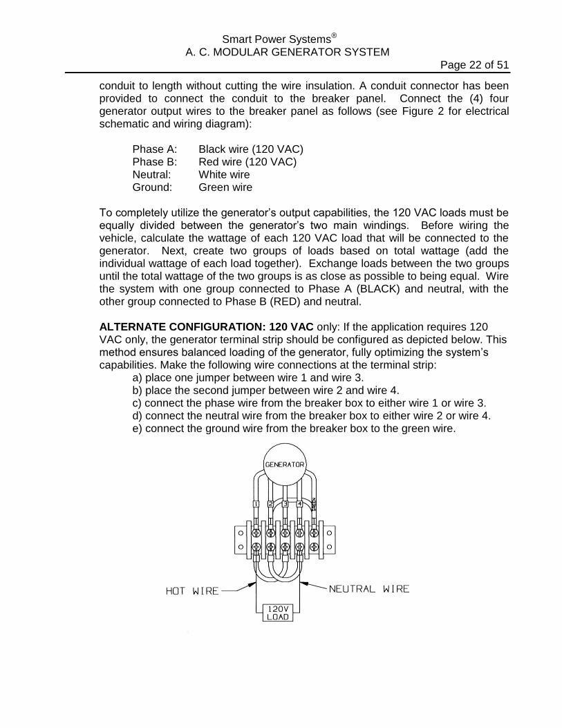
ALTERNATE CONFIGURATION: 120 VAC only: If the application requires 120 VAC only, the generator terminal strip should be configured as depicted below. This method ensures balanced loading of the generator, fully optimizing the system’s capabilities. Make the following wire connections at the terminal strip:
a) place one jumper between wire 1 and wire 3. b) place the second jumper between wire 2 and wire 4. c) connect the phase wire from the breaker box to either wire 1 or wire 3. d) connect the neutral wire from the breaker box to either wire 2 or wire 4. e) connect the ground wire from the breaker box to the green wire.
Smart Power Systems® A. C. MODULAR GENERATOR SYSTEM
Page 23 of 51
WARNING:
To ensure proper voltage regulation, during the operation of generator system, the load difference between Phase A and Phase B must never exceed 20%. Damage to generator system caused by operating it with an unbalance load will void the system’s warranty. Wiring of the A.C. modular generator system and electrical distribution throughout the vehicle must be done in accordance with applicable sections in the National Fire Protection Association’s document NFPA 1901, the National Electrical Code® and/or other applicable, recognized electrical code and by a certified electrician. Smart Power Systems® A.C. modular generators are supplied with the neutral bonded to ground. Refer to National Fire Protection Association’s document NFPA
1901, National Electrical Code, and/or other applicable recognized electrical codes before wiring an SPS A.C. modular generator system. Never wire any loads to the generator’s output without a circuit breaker in series with the load. Damage to the generator, to the components within that circuit, electrical shock, or fire may result if a short occurs in an unprotected circuit. Run all 120 VAC and 240 VAC electrical connections between the generator and the distribution panel in conduit. Bypassing the SPS factory installed breaker will void the system’s warranty. Replacement breakers must be obtained from Smart Power Systems® approved sources only. Do not perform any wiring installations or modifications while the system is operating. The A.C. modular generator system will generate enough voltage to produce a fatal shock. Never touch any live connections while the system is operating. 9. Connect 12 VDC (vehicle battery positive) to the generator’s system controller input
(reference Figure 2). Connect the RED wire from the system controller, marked “Vehicle +12V supply” to the vehicle’s ignition circuit through a 30 amp fuse. Connect the BLACK wire to the vehicle’s ground (vehicle battery negative).
WARNING: 12 volts DC must be directly applied to the generator system controller whenever the hydraulic pump is engaged. Failure to do so may cause excessive fluid temperature, damaging the system components and will void the warranty. Never come near a running fan with loose items such as long hair, clothing, jewelry, ties, items that can fall out of pockets, etc.
Smart Power Systems® A. C. MODULAR GENERATOR SYSTEM
Page 24 of 51
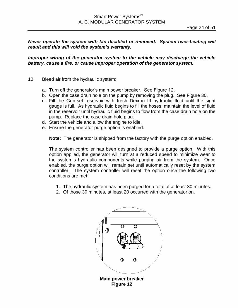
Never operate the system with fan disabled or removed. System over-heating will result and this will void the system’s warranty. Improper wiring of the generator system to the vehicle may discharge the vehicle battery, cause a fire, or cause improper operation of the generator system. 10. Bleed air from the hydraulic system:
a. Turn off the generator’s main power breaker. See Figure 12. b. Open the case drain hole on the pump by removing the plug. See Figure 30. c. Fill the Gen-set reservoir with fresh Dexron III hydraulic fluid until the sight
gauge is full. As hydraulic fluid begins to fill the hoses, maintain the level of fluid in the reservoir until hydraulic fluid begins to flow from the case drain hole on the pump. Replace the case drain hole plug.
d. Start the vehicle and allow the engine to idle. e. Ensure the generator purge option is enabled.
Note: The generator is shipped from the factory with the purge option enabled.
The system controller has been designed to provide a purge option. With this option applied, the generator will turn at a reduced speed to minimize wear to the system’s hydraulic components while purging air from the system. Once enabled, the purge option will remain set until automatically reset by the system controller. The system controller will reset the option once the following two conditions are met:
1. The hydraulic system has been purged for a total of at least 30 minutes. 2. Of those 30 minutes, at least 20 occurred with the generator on.
Main power breaker
Figure 12
Smart Power Systems® A. C. MODULAR GENERATOR SYSTEM
Page 25 of 51
WARNING:
Never operate the system without the filler/breather plug installed. Contaminants may enter the hydraulic fluid through the filler opening, causing premature wear on the hydraulic components and void the system’s warranty. Never apply a load to the generator while there is air trapped in the hydraulic fluid. Damage to the system’s hydraulic components, as well as ruptured hoses, may result and void the system’s warranty. Always run the purge cycle after installation, after replacing the hydraulic fluid and the filter, or after making any other repairs that may allow air into the hydraulic system. Failure to do so will void the system’s warranty.
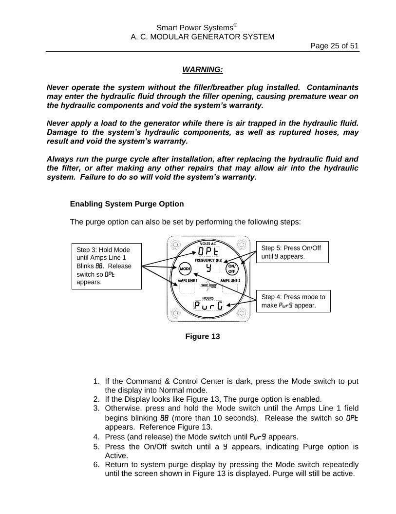
Enabling System Purge Option
The purge option can also be set by performing the following steps:
Step 3: Hold Mode until Amps Line 1
Blinks . Release
switch so appears.
Step 4: Press mode to
make appear.
Step 5: Press On/Off
until appears.
Figure 13
1. If the Command & Control Center is dark, press the Mode switch to put
the display into Normal mode. 2. If the Display looks like Figure 13, The purge option is enabled. 3. Otherwise, press and hold the Mode switch until the Amps Line 1 field
begins blinking (more than 10 seconds). Release the switch so appears. Reference Figure 13.
4. Press (and release) the Mode switch until appears.
5. Press the On/Off switch until a appears, indicating Purge option is Active.
6. Return to system purge display by pressing the Mode switch repeatedly until the screen shown in Figure 13 is displayed. Purge will still be active.
Smart Power Systems® A. C. MODULAR GENERATOR SYSTEM
Page 26 of 51
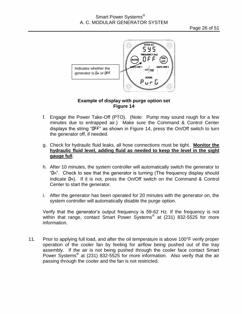
Indicates whether the
generator is or
Example of display with purge option set Figure 14
f. Engage the Power Take-Off (PTO). (Note: Pump may sound rough for a few
minutes due to entrapped air.) Make sure the Command & Control Center
displays the string “” as shown in Figure 14, press the On/Off switch to turn the generator off, if needed.
g. Check for hydraulic fluid leaks, all hose connections must be tight. Monitor the
hydraulic fluid level, adding fluid as needed to keep the level in the sight gauge full.
h. After 10 minutes, the system controller will automatically switch the generator to
“”. Check to see that the generator is turning (The frequency display should
indicate ). If it is not, press the On/Off switch on the Command & Control Center to start the generator.
i. After the generator has been operated for 20 minutes with the generator on, the
system controller will automatically disable the purge option.
Verify that the generator’s output frequency is 59-62 Hz. If the frequency is not within that range, contact Smart Power Systems® at (231) 832-5525 for more information.
11. Prior to applying full load, and after the oil temperature is above 100°F verify proper
operation of the cooler fan by feeling for airflow being pushed out of the tray assembly. If the air is not being pushed through the cooler face contact Smart Power Systems® at (231) 832-5525 for more information. Also verify that the air passing through the cooler and the fan is not restricted.

Smart Power Systems® A. C. MODULAR GENERATOR SYSTEM
Page 27 of 51
WARNING:
The SPS Model HR-6.2, HR-8, HR-10 and HR-110 have been pre-set at the factory to provide correct frequency and voltage. No pump adjustment is required. If it appears the pump needs to be adjusted, contact Smart Power Systems® at (231) 832-5525 before proceeding. Damage to generator from improper pump adjustment will void the system’s warranty. Improper ventilation will result in system overheating, reduced performance and possible damage to the system and/or cause personal injury. If the system is installed such that improper ventilation exists, the system’s warranty will be voided. 12. Set “auto-start” option.
If the auto-start option is enabled, the generator will begin generating electricity whenever the PTO is engaged. If the auto-start option is disabled, the generator will not output electricity after PTO engagement until the “on/off” switch is pressed. Select the auto-start function by performing the following steps:
Step b: Hold Mode until
Amps Line 1 Blinks .
Release switch so
and appear.
Step c: Press On/Off until the desired value appears
Figure 15
Smart Power Systems® A. C. MODULAR GENERATOR SYSTEM
Page 28 of 51
Enabling Auto-Start Option
a. If the Command & Control Center is dark, press the Mode switch to put the
Command & Control Center into Normal mode.
b. Press and hold the Mode switch until the Amps Line 1 field begins blinking
(more than 10 seconds). Release the switch so and appear. Reference Figure 15.
c. Press the On/Off switch until the desired value appears. A means Auto-Start
is enabled, an means Auto-Start is disabled.
d. Return to Normal mode by pressing Mode.
Smart Power Systems® A. C. MODULAR GENERATOR SYSTEM
Page 29 of 51
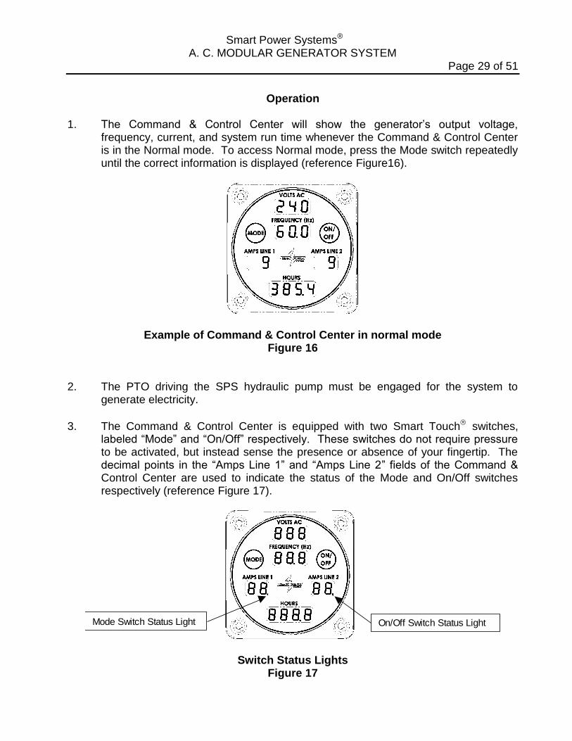
Operation 1. The Command & Control Center will show the generator’s output voltage,
frequency, current, and system run time whenever the Command & Control Center is in the Normal mode. To access Normal mode, press the Mode switch repeatedly until the correct information is displayed (reference Figure16).
Example of Command & Control Center in normal mode Figure 16
2. The PTO driving the SPS hydraulic pump must be engaged for the system to
generate electricity.
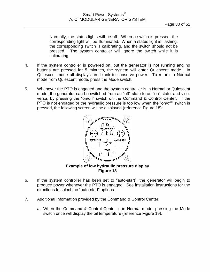
3. The Command & Control Center is equipped with two Smart Touch switches, labeled “Mode” and “On/Off” respectively. These switches do not require pressure to be activated, but instead sense the presence or absence of your fingertip. The decimal points in the “Amps Line 1” and “Amps Line 2” fields of the Command & Control Center are used to indicate the status of the Mode and On/Off switches respectively (reference Figure 17).
Mode Switch Status Light On/Off Switch Status Light
Switch Status Lights Figure 17
Smart Power Systems® A. C. MODULAR GENERATOR SYSTEM
Page 30 of 51
Normally, the status lights will be off. When a switch is pressed, the corresponding light will be illuminated. When a status light is flashing, the corresponding switch is calibrating, and the switch should not be pressed. The system controller will ignore the switch while it is calibrating.
4. If the system controller is powered on, but the generator is not running and no
buttons are pressed for 5 minutes, the system will enter Quiescent mode. In Quiescent mode all displays are blank to conserve power. To return to Normal mode from Quiescent mode, press the Mode switch.
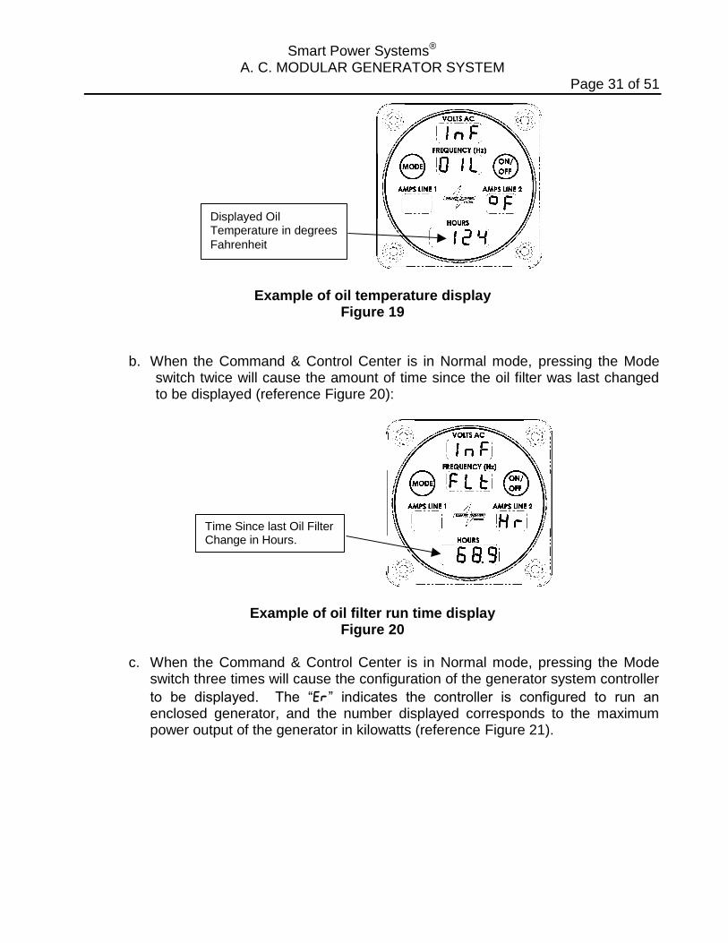
5. Whenever the PTO is engaged and the system controller is in Normal or Quiescent
mode, the generator can be switched from an “off” state to an “on” state, and vise-versa, by pressing the “on/off” switch on the Command & Control Center. If the PTO is not engaged or the hydraulic pressure is too low when the “on/off” switch is pressed, the following screen will be displayed (reference Figure 18):
Example of low hydraulic pressure display
Figure 18 6. If the system controller has been set to “auto-start”, the generator will begin to
produce power whenever the PTO is engaged. See installation instructions for the directions to select the “auto-start” options.
7. Additional Information provided by the Command & Control Center:
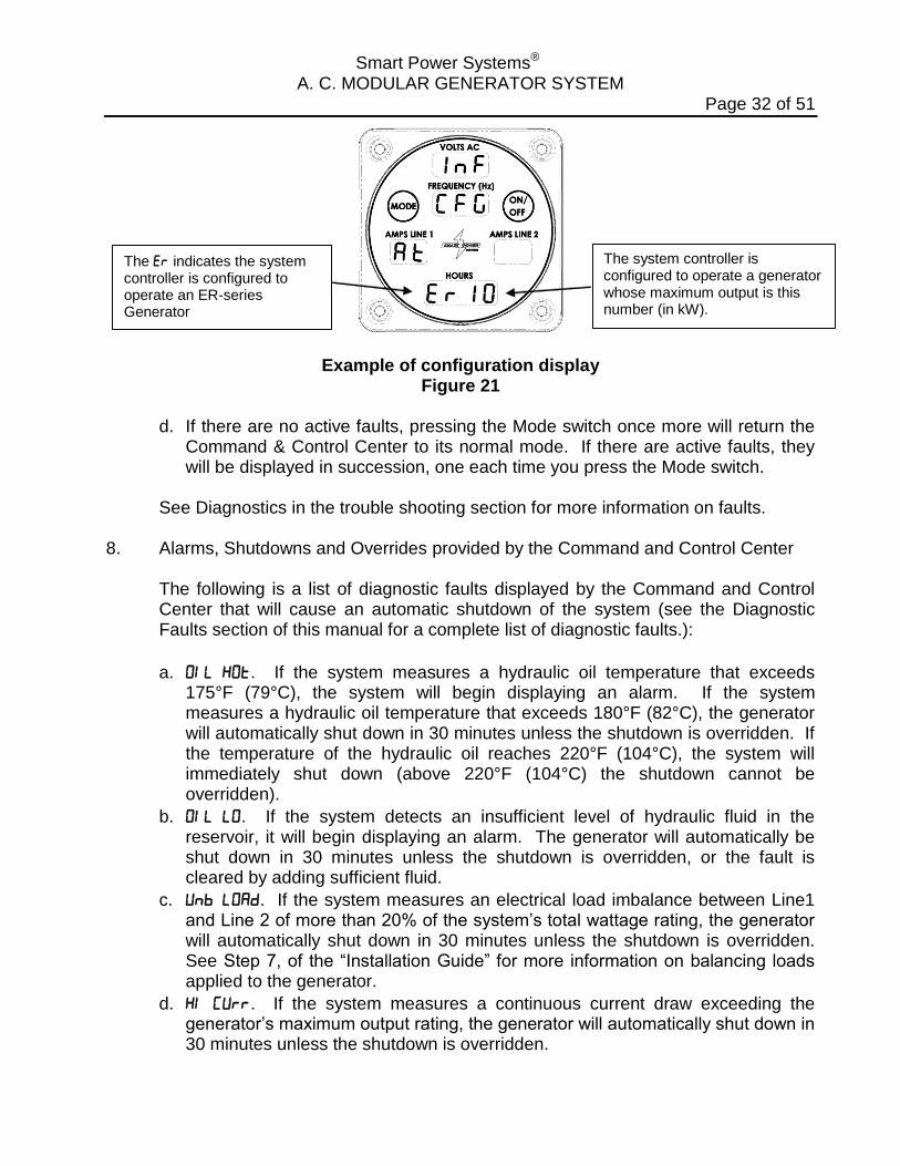
a. When the Command & Control Center is in Normal mode, pressing the Mode switch once will display the oil temperature (reference Figure 19).
Smart Power Systems® A. C. MODULAR GENERATOR SYSTEM
Page 31 of 51
Displayed Oil Temperature in degrees
Fahrenheit
Example of oil temperature display Figure 19
b. When the Command & Control Center is in Normal mode, pressing the Mode switch twice will cause the amount of time since the oil filter was last changed to be displayed (reference Figure 20):
Time Since last Oil Filter Change in Hours.
Example of oil filter run time display Figure 20
c. When the Command & Control Center is in Normal mode, pressing the Mode
switch three times will cause the configuration of the generator system controller
to be displayed. The “” indicates the controller is configured to run an enclosed generator, and the number displayed corresponds to the maximum power output of the generator in kilowatts (reference Figure 21).
Smart Power Systems® A. C. MODULAR GENERATOR SYSTEM
Page 32 of 51
The system controller is configured to operate a generator whose maximum output is this number (in kW).
The indicates the system controller is configured to operate an ER-series Generator
Example of configuration display
Figure 21
d. If there are no active faults, pressing the Mode switch once more will return the Command & Control Center to its normal mode. If there are active faults, they will be displayed in succession, one each time you press the Mode switch.
See Diagnostics in the trouble shooting section for more information on faults.
8. Alarms, Shutdowns and Overrides provided by the Command and Control Center
The following is a list of diagnostic faults displayed by the Command and Control Center that will cause an automatic shutdown of the system (see the Diagnostic Faults section of this manual for a complete list of diagnostic faults.):
a. . If the system measures a hydraulic oil temperature that exceeds 175°F (79°C), the system will begin displaying an alarm. If the system measures a hydraulic oil temperature that exceeds 180°F (82°C), the generator will automatically shut down in 30 minutes unless the shutdown is overridden. If the temperature of the hydraulic oil reaches 220°F (104°C), the system will immediately shut down (above 220°F (104°C) the shutdown cannot be overridden).
b. . If the system detects an insufficient level of hydraulic fluid in the reservoir, it will begin displaying an alarm. The generator will automatically be shut down in 30 minutes unless the shutdown is overridden, or the fault is cleared by adding sufficient fluid.
c. . If the system measures an electrical load imbalance between Line1 and Line 2 of more than 20% of the system’s total wattage rating, the generator will automatically shut down in 30 minutes unless the shutdown is overridden. See Step 7, of the “Installation Guide” for more information on balancing loads applied to the generator.
d. . If the system measures a continuous current draw exceeding the generator’s maximum output rating, the generator will automatically shut down in 30 minutes unless the shutdown is overridden.
Smart Power Systems® A. C. MODULAR GENERATOR SYSTEM
Page 33 of 51
e. . If the system measures an output voltage that is too low or too high the generator will automatically shut down in 30 minutes unless the shutdown is overridden.
f. . If the system detects a faulty temperature sensor, the generator will automatically shut down in 30 minutes unless the shutdown is overridden.
g. . If the oil filter service warning is ignored, and the oil filter is not changed following the procedure outlined in the “Maintenance Instructions” section of this manual, the generator will automatically shut down in 30 minutes unless the shutdown is overridden.
WARNING:
Overriding an automatic system shutdown may result in permanent damage to the system and/or degrade the system’s performance. Overriding an automatic system shutdown may void warranty. The system’s electronic controller records whenever an override function is performed. Always avoid overriding a shutdown if possible.
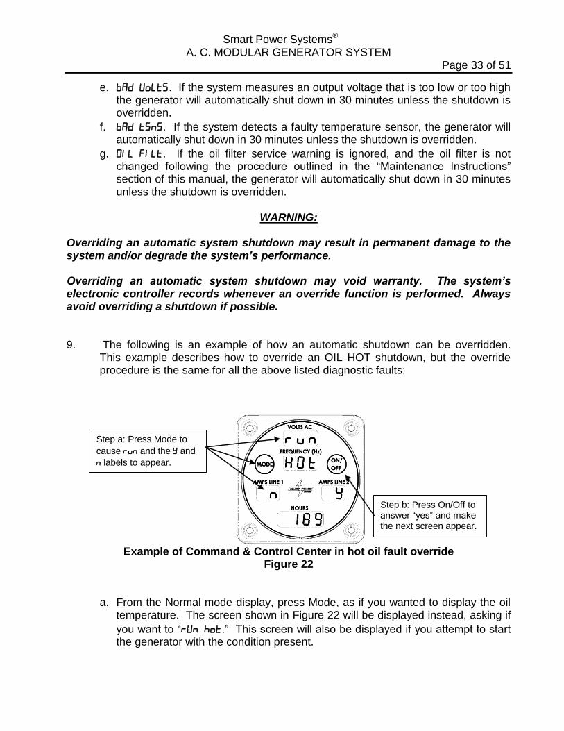
9. The following is an example of how an automatic shutdown can be overridden. This example describes how to override an OIL HOT shutdown, but the override procedure is the same for all the above listed diagnostic faults:
Step a: Press Mode to
cause and the and
labels to appear.
Step b: Press On/Off to answer “yes” and make the next screen appear.
Example of Command & Control Center in hot oil fault override
Figure 22
a. From the Normal mode display, press Mode, as if you wanted to display the oil temperature. The screen shown in Figure 22 will be displayed instead, asking if
you want to “.” This screen will also be displayed if you attempt to start the generator with the condition present.
Smart Power Systems® A. C. MODULAR GENERATOR SYSTEM
Page 34 of 51
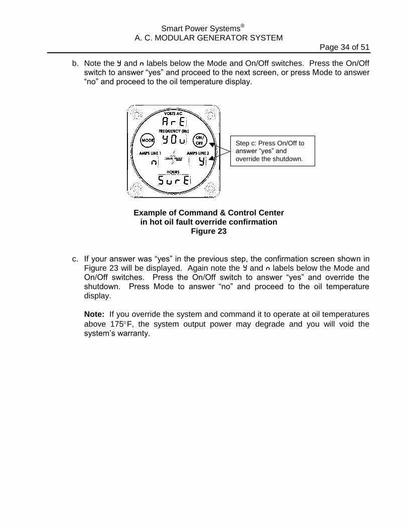
b. Note the and labels below the Mode and On/Off switches. Press the On/Off switch to answer “yes” and proceed to the next screen, or press Mode to answer “no” and proceed to the oil temperature display.
Step c: Press On/Off to answer “yes” and
override the shutdown.
Example of Command & Control Center in hot oil fault override confirmation
Figure 23
c. If your answer was “yes” in the previous step, the confirmation screen shown in Figure 23 will be displayed. Again note the y and n labels below the Mode and On/Off switches. Press the On/Off switch to answer “yes” and override the shutdown. Press Mode to answer “no” and proceed to the oil temperature display.
Note: If you override the system and command it to operate at oil temperatures
above 175F, the system output power may degrade and you will void the system’s warranty.

Smart Power Systems® A. C. MODULAR GENERATOR SYSTEM
Page 35 of 51
Special Operating Instructions Cold Weather Procedure: It is strongly recommended that the generator PTO be engaged prior to leaving a heated garage or fire station in cold weather. The system will generate enough heat to keep its hydraulic fluid viscosity low enough for proper operation, in all but the most extremes of low ambient air temperatures.
If the generator system is “started” when the hydraulic oil temperature is below 40F, the following message will be displayed on the Command & Control Center (reference Figure 24):
Message advising theoil is cold (less than
40F)
Measured oiltemperature in
degrees fahrenheit
Example of Command & Control Center when operating with cold hydraulic fluid
Figure 24 Operating Modes when the system START button is activated (or when the system is in “autostart”):
When the meter displays hydraulic oil temperatures below 20F, the hydraulic system will bypass the generator motor and the generator will not produce power. This mode warms the hydraulic oil.
When the meter displays hydraulic oil temperatures between 20 and 40F, the generator rotor will turn at a reduced RPM and the generator will not produce
power. This warms the hydraulic oil to 40F.
When the meter displays hydraulic oil temperatures that exceed 40F, the system will then commence full power generating operations.
Smart Power Systems® A. C. MODULAR GENERATOR SYSTEM
Page 36 of 51
Maintenance Instructions
WARNING: Do not perform maintenance while system is running. 1. Perform regular, periodic checks to verify:
a. The cooler, the cooler fan and generator vents are not plugged by debris. b. There are no fluid leaks within the framework of the generator, along the hoses,
or at the pump. c. The hoses are not cut, chaffed, bulged or kinked. d. That no electrical connections are loose. e. That the hydraulic fluid level in the reservoir is between ½ to ¾ full in the sight
gage and the hydraulic fluid is clean and bright red in color. f. That the bolts mounting the pump to the PTO are not loose. g. If the hydraulic fluid appears dirty or black in the reservoir sight gage, replace
the fluid and filter immediately. Also, if the hydraulic fluid sustains a temperature over 175° F, replace the fluid immediately. Oxidation can occur naturally over time and can be accelerated with over temperature operation, affecting generator output. Always change the filter when the hydraulic fluid is changed.
WARNING:
When adding or replacing hydraulic fluid, always use clean, new Dexron III fluid. Do not power wash the generator. Doing so will void the system’s warranty. Do not allow liquid to enter the generator. If the outside of the generator requires cleaning, wipe surface with a damp cloth. Clean the Command and Control Center using soap and water with a soft cloth only. Improper cleaning, handling and use that may scratch, gouge, chip, fade or otherwise damage the surface coating and display surfaces are not covered under the device warranty. 2. Replace the oil filter after every 250 hours of operation, or every three (3) years
(whichever comes first). Use Dexron III fluid and one of the following filters:
Hydac 0080 MA010 P Puralator 20101 Fram P-1653-A (10 Micron 8 GPM) WIX 51551 (10 Micron 8 GPM)
Lubricate the oil filter gasket with Dexron III before installation to permit proper sealing of the filter.
Smart Power Systems® A. C. MODULAR GENERATOR SYSTEM
Page 37 of 51
WARNING:
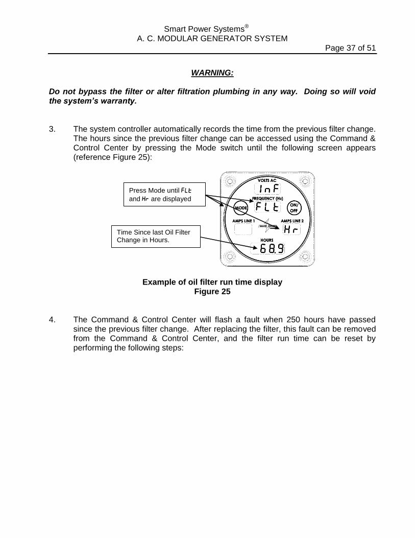
Do not bypass the filter or alter filtration plumbing in any way. Doing so will void the system’s warranty. 3. The system controller automatically records the time from the previous filter change.
The hours since the previous filter change can be accessed using the Command & Control Center by pressing the Mode switch until the following screen appears (reference Figure 25):
Time Since last Oil Filter Change in Hours.
Press Mode until
and are displayed
Example of oil filter run time display Figure 25
4. The Command & Control Center will flash a fault when 250 hours have passed since the previous filter change. After replacing the filter, this fault can be removed from the Command & Control Center, and the filter run time can be reset by performing the following steps:
Smart Power Systems® A. C. MODULAR GENERATOR SYSTEM
Page 38 of 51
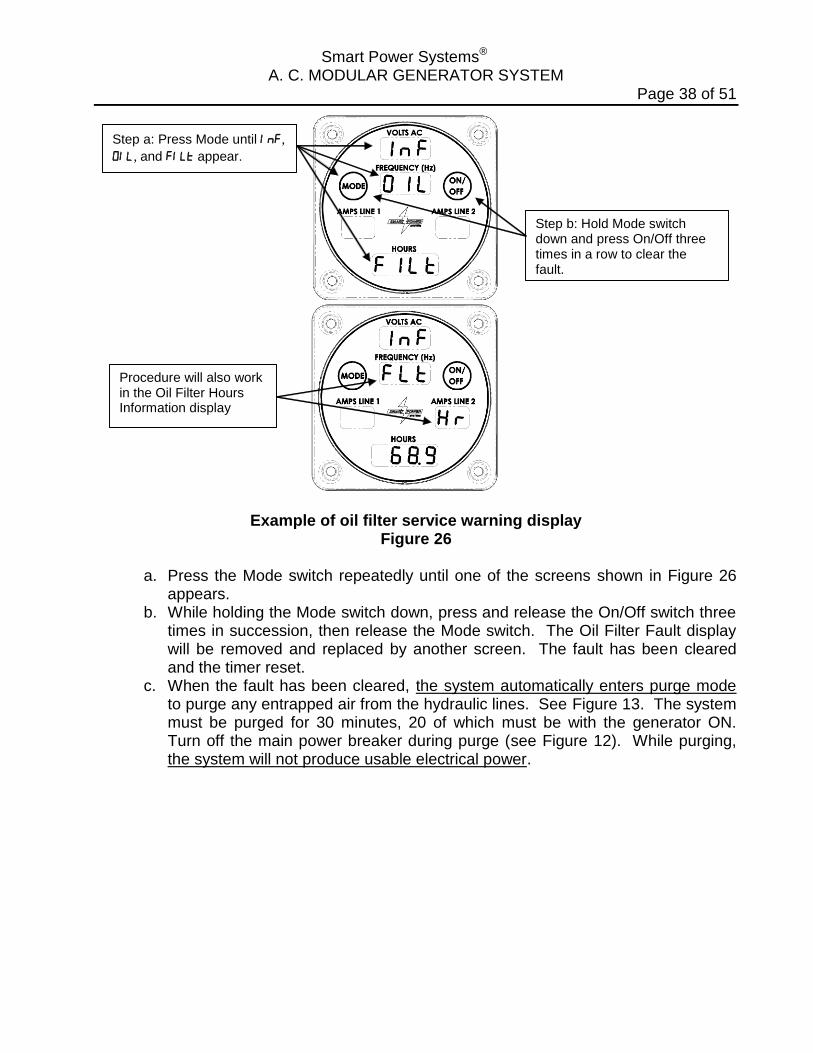
Step a: Press Mode until ,
, and appear.
Step b: Hold Mode switch down and press On/Off three times in a row to clear the fault.
Procedure will also work in the Oil Filter Hours Information display
Example of oil filter service warning display Figure 26
a. Press the Mode switch repeatedly until one of the screens shown in Figure 26
appears. b. While holding the Mode switch down, press and release the On/Off switch three
times in succession, then release the Mode switch. The Oil Filter Fault display will be removed and replaced by another screen. The fault has been cleared and the timer reset.
c. When the fault has been cleared, the system automatically enters purge mode to purge any entrapped air from the hydraulic lines. See Figure 13. The system must be purged for 30 minutes, 20 of which must be with the generator ON. Turn off the main power breaker during purge (see Figure 12). While purging, the system will not produce usable electrical power.
Smart Power Systems® A. C. MODULAR GENERATOR SYSTEM
Page 39 of 51
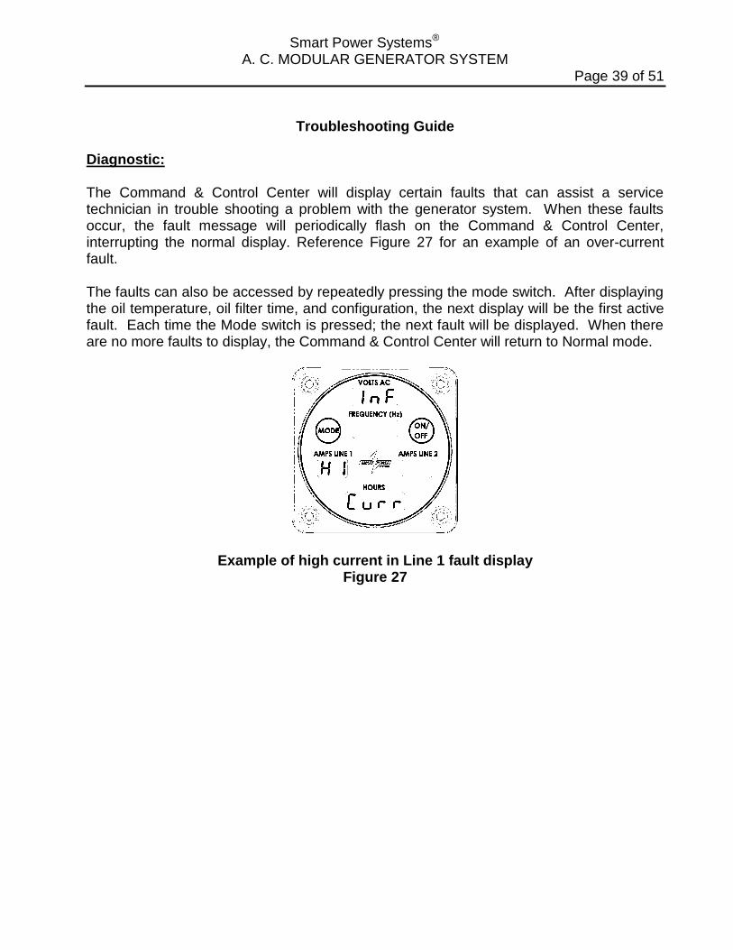
Troubleshooting Guide Diagnostic: The Command & Control Center will display certain faults that can assist a service technician in trouble shooting a problem with the generator system. When these faults occur, the fault message will periodically flash on the Command & Control Center, interrupting the normal display. Reference Figure 27 for an example of an over-current fault. The faults can also be accessed by repeatedly pressing the mode switch. After displaying the oil temperature, oil filter time, and configuration, the next display will be the first active fault. Each time the Mode switch is pressed; the next fault will be displayed. When there are no more faults to display, the Command & Control Center will return to Normal mode.
Example of high current in Line 1 fault display Figure 27
Smart Power Systems® A. C. MODULAR GENERATOR SYSTEM
Page 40 of 51
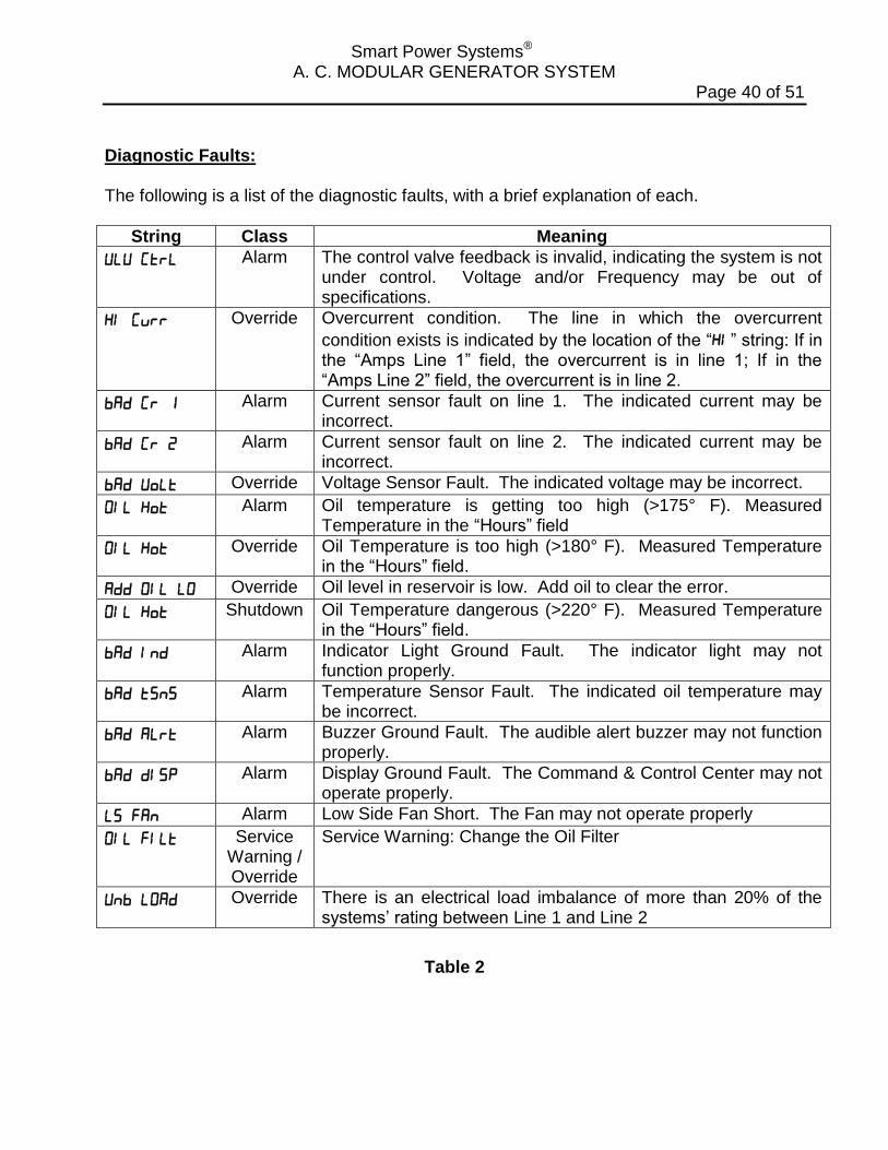
Diagnostic Faults: The following is a list of the diagnostic faults, with a brief explanation of each.
String Class Meaning
Alarm The control valve feedback is invalid, indicating the system is not under control. Voltage and/or Frequency may be out of specifications.
Override Overcurrent condition. The line in which the overcurrent
condition exists is indicated by the location of the “” string: If in the “Amps Line 1” field, the overcurrent is in line 1; If in the “Amps Line 2” field, the overcurrent is in line 2.
Alarm Current sensor fault on line 1. The indicated current may be incorrect.
Alarm Current sensor fault on line 2. The indicated current may be incorrect.
Override Voltage Sensor Fault. The indicated voltage may be incorrect.
Alarm Oil temperature is getting too high (>175° F). Measured Temperature in the “Hours” field
Override Oil Temperature is too high (>180° F). Measured Temperature in the “Hours” field.
Override Oil level in reservoir is low. Add oil to clear the error.
Shutdown Oil Temperature dangerous (>220° F). Measured Temperature in the “Hours” field.
Alarm Indicator Light Ground Fault. The indicator light may not function properly.
Alarm Temperature Sensor Fault. The indicated oil temperature may be incorrect.
Alarm Buzzer Ground Fault. The audible alert buzzer may not function properly.
Alarm Display Ground Fault. The Command & Control Center may not operate properly.
Alarm Low Side Fan Short. The Fan may not operate properly
Service Warning / Override
Service Warning: Change the Oil Filter
Override There is an electrical load imbalance of more than 20% of the systems’ rating between Line 1 and Line 2
Table 2
Smart Power Systems® A. C. MODULAR GENERATOR SYSTEM
Page 41 of 51
Note: The fault “Classes” are defined in the table below:
Class Meaning Service Warning Normal maintenance needs to take place.
Alarm A condition requires the immediate attention of the operator.
Shutdown A condition causes the immediate shutdown of the generator.
Override A condition that will cause the generator to be shut down in 30 minutes unless explicitly overridden by the operator.
Table 3 Hydraulic Problems: 1. Cavitation:
Cavitation is caused by trying to pump more fluid than is available at the pump inlet due to system restrictions. Pump cavitation sounds like “marbles” passing through the pump. Conditions frequently associated with cavitation are the following: a. Too many restrictive fittings such as elbows and reducers on the pump inlet
hose. b. Tight bends or kinks in pump inlet hose and/or tubing. c. Insufficient tray height above the pump, resulting in low head pressures. d. Under sized pump inlet hose (minimum pump inlet hose size is 1”). e. Excessive long inlet hose (may be corrected by using larger hose). f. Cold hydraulic fluid.
Finding the cause and correcting it should stop cavitation. Install a 0-25 psig gauge in line between inlet hose fitting and pump inlet port. Engage PTO. Operate genset with no load for twenty minutes to purge air out of the system. Observe the pressure reading. The pressure should always be positive. If the pressure is not positive, system repair/rework is required.
2. Aeration:
Aeration results from air being drawn into the system through leak paths or a low fluid condition. Aeration makes a “growling” sound and produces visible bubbles in the fluid stream and/or reservoir. Conditions frequently associated with aeration are the following:
a. Air leaks in the pump inlet flow path. b. Low fluid level allowing air to be drawn into the system.
Verify there are no air bubbles in the fluid by viewing inside the reservoir. If there are air bubbles, check fluid level, tighten all fittings, and look for cracked fittings or hose leaks on the pump inlet line. Replace any suspect parts and adjust fluid level.
Smart Power Systems® A. C. MODULAR GENERATOR SYSTEM
Page 42 of 51
After correcting any problems, again operate the generator twenty minutes to purge air out of the hydraulic fluid. Note that any bubbles seen in the reservoir indicate leakage in the pump inlet line.
3. Differential Pressure:
Differential pressure between the inlet pressure and the case pressure over 7 psig causes the piston shoes to lift off the swash plate. This occurs due to the excessive lower pressure created on the fill (down) stroke of the piston. When the swash plate begins its upstroke, with pump rotation, it comes back into contact with the piston shoe, creating chatter. NOTE: This is NOT NORMAL. The piston shoes should always remain in contact with the swash plate. The causes of and correction for this problem are the same as for cavitation above.
With the pressure gauge still installed in the suction line at the pump inlet port, install a second gauge (0-50 psig pressure gauge) in the case drain line at the pump case port. Next, engage the PTO and operate the genset with no load for twenty minutes to purge air out of the fluid. Note both gauge readings. If the differential pressure at the case is greater than 7 psig, the suction side plumbing will require evaluation.
Note the following pressure measurements!
Inlet pressures: Should always be positive. Outlet pressure: Approximately 500 psig with no load on the generator. Note: If the gauge is fluctuating, record limits. Case drain pressure to inlet pressure differential: The difference between pump inlet pressure and case drain pressure should not exceed 7 psig. Pump inlet pressure minus case drain pressure should never be less than 7 psig. Verify the installation of the following hydraulic generator hose diameters: a. Inlet hose (suction) on hydraulic pump (attaches to Port “S” on back of pump): 1
inch b. Outlet hose (pressure) on hydraulic pump (attaches to Port “B” on back of
pump): 5/8 inch c. Case drain to hydraulic pump (attaches to Port “L” top side, mid-length of pump):
5/8 inch
Note: The hose diameter appears in print along the length of the hose.
Smart Power Systems® A. C. MODULAR GENERATOR SYSTEM
Page 43 of 51
4. System Overheating:
System overheating may be caused by re-circulation of hot air through oil cooler, dirty or obstructed oil cooler fins, restricted hydraulic fluid flow, excessive generator load, restricted airflow, previously overheated (old) fluid, non-functional fan, or improperly adjusted pump.
a. Check the oil cooler fins for debris or damage. Clean and/or replace cooler. b. Verify that the generator load is not excessive. c. Verify that there is proper ventilation. d. Verify that the DC fan motor is operating properly. e. Verify that warm air from the fan outlet is not being re-circulated through the
cooler. f. Check the hydraulic fluid to see if it is black or darkened. This indicates
overheating or aging. Drain and flush the system. g. Fill with new, clean hydraulic fluid. h. Adjust pump, if necessary, only after contacting Smart Power Systems® at (231)
832-5525. 5. Low Hydraulic Fluid Level In Reservoir:
Low hydraulic fluid level in reservoir can be caused by leaking fittings, hoses or pipes.
a. Check all the fittings for leaks. Tighten any loose fittings that are found (but do
not over-tighten). b. Replace defective fittings. c. Check all tubing for leaks. Repair or replace as necessary.
Smart Power Systems® A. C. MODULAR GENERATOR SYSTEM
Page 44 of 51
Electrical Problems 1. No Output Voltage:
a. No output voltage may be caused by excessive current draw opening the circuit breakers. (The circuit breakers can be found mounted on the generator wiring enclosure.) Remove all electrical loads from the generator and reset breaker(s). Re-engage electrical load in increments. If possible, monitor current draw with the Command & Control Center to determine which portion of the load is causing the breaker to open.
b. The PTO is faulty. Verify that the drive shaft that links the pump to the hydraulic
pump is spinning when the PTO is engaged. If the shaft is not turning, the probable cause of the failure is a non-functional PTO. Contact the PTO manufacture or qualified representative for further information.
c. The generator’s system controller has lost power (reference Figure 2). The
Command & Control Center would stay dark even after the mode and/or on/off switch is pressed. Verify that the vehicle +12V supply has both +12 volts and ground. If 12 volts is not available check the vehicle for a blown fuse or a loose/open electrical connection.
d. The stator field may be shorted or open. With a flashlight, check the generator
windings visible through the ventilation slots. If the windings appear burnt in any area, the generator must be replaced. If the windings are not burnt, disconnect wires 1, 2, 3, and 4 from the terminal strip located in the generator wiring enclosure and make resistance measurement. The resistance between wires 1 and 2, and wires 3 and 4 should be between essentially 0 ohms. Contact Smart Power® Systems at (231) 832-5525 if any problems are found.
WARNING: Do not attempt to measure stator field resistance while the system is operating. Electrical shock may occur.
e. The exciter field may be shorted or open. With a flashlight, check the generator windings visible through the ventilation slots. If the windings appear burnt in any area, the generator must be replaced. If the windings are not burnt, disconnect the exciter field from the field capacitor. Measure the resistance of the exciter field using an ohmmeter. The resistance of the exciter field should be essentially 0 ohms. Contact Smart Power Systems® at (231) 832-5525 if the resistance is outside this range.
Smart Power Systems® A. C. MODULAR GENERATOR SYSTEM
Page 45 of 51
WARNING: Do not attempt to measure the exciter field resistance while the system is operating. Electrical shock may occur.
f. Exciter field capacitor may be faulty. Disconnect the exciter field from the field capacitor. Using a screwdriver, short leads of capacitor together to discharge capacitor. Measure capacitance against its printed rating using a capacitance meter. Note that the capacitors must be disconnected from the generator and each other (if there is more than one) before measuring.
WARNING:
Do not attempt to test the field capacitor with the system running. Electrical shock may occur.
g. The generator drive motor or coupling is faulty. Observe the generator while the
system is engaged. If the coupling is not turning, or if it is turning but the generator is not, one or more of the coupling components may be damaged and must be replaced. Also, verify that the coupling halves are mating. If the coupling halves are not mating, remove the hydraulic motor from the generator to inspect coupling and the rubber insert between the coupling halves. Replace components as necessary, reposition and tighten coupling setscrew so both halves of the coupling are mating correctly.
h. The pump is faulty. If no faults are found in steps a. through g., the problem is
likely to be a non-functional pump. Contact Smart Power Systems® at (231) 832-5525 for further instructions.
Smart Power Systems® A. C. MODULAR GENERATOR SYSTEM
Page 46 of 51
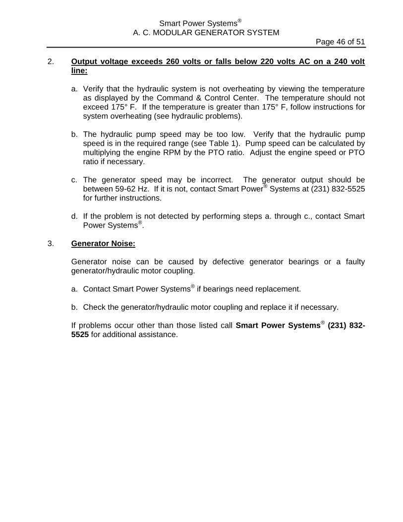
2. Output voltage exceeds 260 volts or falls below 220 volts AC on a 240 volt line:
a. Verify that the hydraulic system is not overheating by viewing the temperature
as displayed by the Command & Control Center. The temperature should not exceed 175° F. If the temperature is greater than 175° F, follow instructions for system overheating (see hydraulic problems).
b. The hydraulic pump speed may be too low. Verify that the hydraulic pump
speed is in the required range (see Table 1). Pump speed can be calculated by multiplying the engine RPM by the PTO ratio. Adjust the engine speed or PTO ratio if necessary.
c. The generator speed may be incorrect. The generator output should be
between 59-62 Hz. If it is not, contact Smart Power® Systems at (231) 832-5525 for further instructions.
d. If the problem is not detected by performing steps a. through c., contact Smart
Power Systems®. 3. Generator Noise:
Generator noise can be caused by defective generator bearings or a faulty generator/hydraulic motor coupling.
a. Contact Smart Power Systems® if bearings need replacement. b. Check the generator/hydraulic motor coupling and replace it if necessary.
If problems occur other than those listed call Smart Power Systems® (231) 832-5525 for additional assistance.
Smart Power Systems® A. C. MODULAR GENERATOR SYSTEM
Page 47 of 51
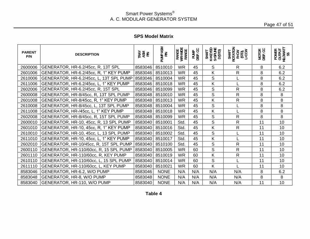
SPS Model Matrix
PARENT P/N
DESCRIPTION
TR
AY
ASM
P/N
PU
MP A
SM
P/N
RA
NG
E
WR
=WID
E
RA
NG
E
PU
MP
DIS
P. C
C
SH
AFT
K=K
EYED
S=S
PLIN
E
D (S
TD
)
SH
AFT
RO
TA
TIO
N
R=C
W
(STD
),
L=C
CW
MO
TO
R
DIS
P. C
C
PO
WER
OU
TPU
T
KIL
OW
ATT
S5
2600006 GENERATOR, HR-6.2/45cc, R, 13T SPL PUMP
8583046 8510010 WR 45 S R 8 6.2
2601006 GENERATOR, HR-6.2/45cc, R, 1” KEY PUMP 8583046 8510013 WR 45 K R 8 6.2
2610006 GENERATOR, HR-6.2/45cc, L, 13T SPL PUMP 8583046 8510004 WR 45 S L 8 6.2
2611006 GENERATOR, HR-6.2/45cc, L, 1” KEY PUMP 8583046 8510018 WR 45 K L 8 6.2
2602006 GENERATOR, HR-6.2/45cc, R, 15T SPL PUMP
8583046 8510099 WR 45 S R 8 6.2
2600008 GENERATOR, HR-8/45cc, R, 13T SPL PUMP 8583048 8510010 WR 45 S R 8 8
2601008 GENERATOR, HR-8/45cc, R, 1” KEY PUMP 8583048 8510013 WR 45 K R 8 8
2610008 GENERATOR, HR-8/45cc, L, 13T SPL PUMP 8583048 8510004 WR 45 S L 8 8
2611008 GENERATOR, HR-/45cc, L, 1” KEY PUMP 8583048 8510018 WR 45 K L 8 8
2602008 GENERATOR, HR-8/45cc, R, 15T SPL PUMP 8583048 8510099 WR 45 S R 8 8
2600010 GENERATOR, HR-10, 45cc, R, 13 SPL PUMP 8583040 8510001 Std. 45 S R 11 10
2601010 GENERATOR, HR-10, 45cc, R, 1” KEY PUMP 8583040 8510016 Std. 45 K R 11 10
2610010 GENERATOR, HR-10, 45cc, L, 13 SPL PUMP 8583040 8510002 Std. 45 S L 11 10
2611010 GENERATOR, HR-10, 45cc, L, 1” KEY PUMP 8583040 8510017 Std. 45 K L 11 10
2602010 GENERATOR, HR-10/45cc, R, 15T SPL PUMP 8583040 8510100 Std. 45 S R 11 10
2600110 GENERATOR, HR-110/60cc, R, 15 SPL PUMP 8583040 8510005 WR 60 S R 11 10
2601110 GENERATOR, HR-110/60cc, R, KEY PUMP 8583040 8510019 WR 60 K R 11 10
2610110 GENERATOR, HR-110/60cc, L, 15 SPL PUMP 8583040 8510014 WR 60 S L 11 10
2611110 GENERATOR, HR-110/60cc, L, KEY PUMP 8583040 8510021 WR 60 K L 11 10
8583046 GENERATOR, HR-6.2, W/O PUMP 8583046 NONE N/A N/A N/A N/A 8 6.2
8583048 GENERATOR, HR-8, W/O PUMP 8583048 NONE N/A N/A N/A N/A 8 8
8583040 GENERATOR, HR-110, W/O PUMP 8583040 NONE N/A N/A N/A N/A 11 10
Table 4
Smart Power Systems® A. C. MODULAR GENERATOR SYSTEM
Page 48 of 51
Pump Adjustment
WARNING:
The SPS Electronic Controlled Generators have been pre-set at the factory to provide correct frequency and voltage, no pump adjustments are required. If it appears the pump need to be adjusted, contact SPS at (231) 832-5525 before proceeding. Damage to the generator from improper pump adjustments will void the system’s warranty. To prevent permanent, un-repairable damage to the generator, never adjust the hydraulic pump so the generator’s output frequency exceeds 65 Hz. Make adjustments to the hydraulic pump flow control with all electrical loads disconnected from generator. Never adjust the pump’s pressure control. Reasons for adjusting the pump: 1. Generated output frequency is “too low.” Verify output frequency when the vehicle
is in fast idle and oil temperature is below 160F. If the frequency drops below 59Hz, the pump output flow may need to be increased.
2. The hydraulic system is running excessively hot: If the system’s oil temperature is
running above 160F with an ambient air temperature of 80F, the pump output flow may need to be decreased. Before making any adjustment, verify the system is getting adequate ventilation, that the fans are both operating, the oil cooler air passageways are not plugged and the hot air exiting the cooler is not being drawn back through the cooler. Operate system after correcting ventilation problems to validate whether the system still overheats prior to making pump adjustment.
Note: The generator’s output frequency cannot be decreased by adjusting the pump flow. If the generator output frequency is too high, contact SPS at (231) 832-5525 for further instructions.
Pump adjustment procedure: 1. Enable the generator Pump Set option.
The system controller has been designed to provide a Pump Set option. With this option applied, the generator will turn at the maximum speed allowed by the hydraulic pump to allow proper adjustment of the pump’s flow.
Smart Power Systems® A. C. MODULAR GENERATOR SYSTEM
Page 49 of 51
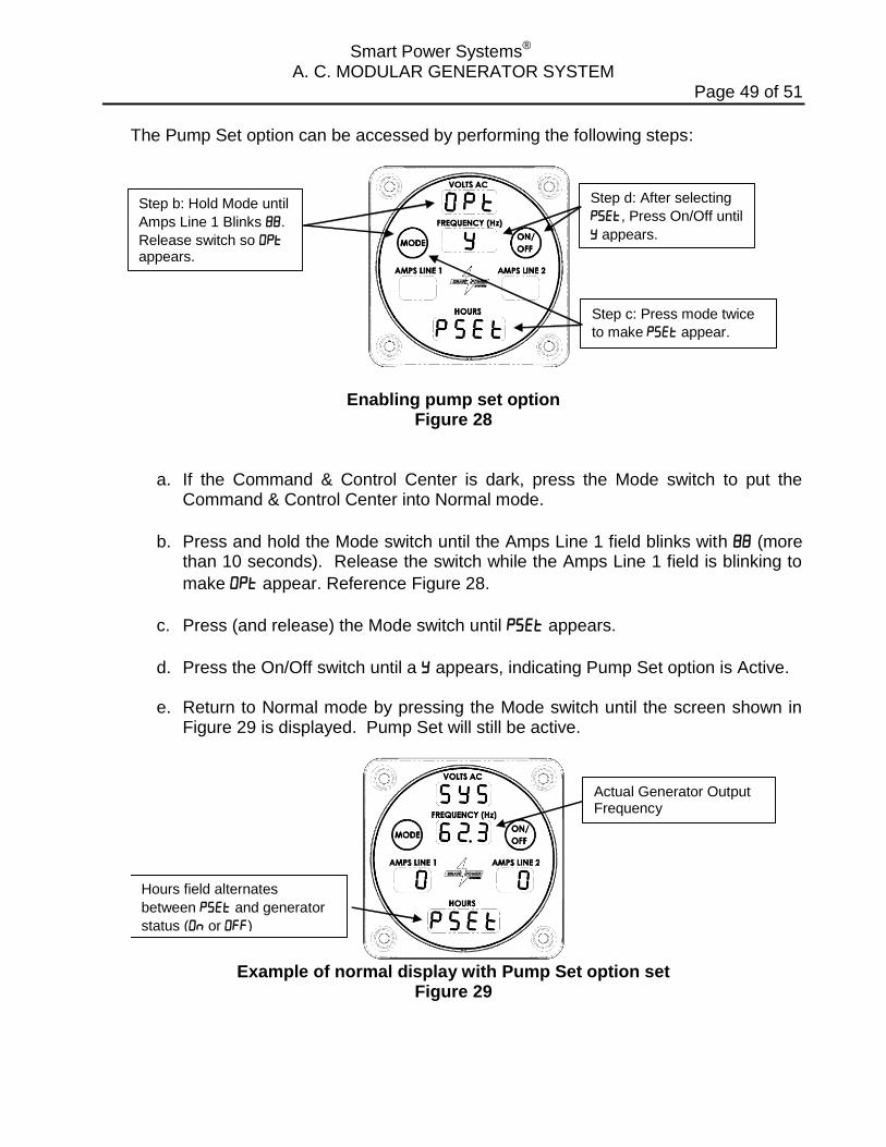
The Pump Set option can be accessed by performing the following steps:
Step b: Hold Mode until
Amps Line 1 Blinks .
Release switch so appears.
Step c: Press mode twice
to make appear.
Step d: After selecting
, Press On/Off until
appears.
Enabling pump set option Figure 28
a. If the Command & Control Center is dark, press the Mode switch to put the Command & Control Center into Normal mode.
b. Press and hold the Mode switch until the Amps Line 1 field blinks with (more than 10 seconds). Release the switch while the Amps Line 1 field is blinking to
make appear. Reference Figure 28.
c. Press (and release) the Mode switch until appears.
d. Press the On/Off switch until a appears, indicating Pump Set option is Active.
e. Return to Normal mode by pressing the Mode switch until the screen shown in Figure 29 is displayed. Pump Set will still be active.
Hours field alternates
between and generator
status ( or )
Actual Generator Output Frequency
Example of normal display with Pump Set option set
Figure 29
Smart Power Systems® A. C. MODULAR GENERATOR SYSTEM
Page 50 of 51
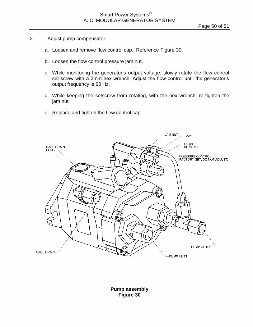
2. Adjust pump compensator:
a. Loosen and remove flow control cap. Reference Figure 30. b. Loosen the flow control pressure jam nut. c. While monitoring the generator’s output voltage, slowly rotate the flow control
set screw with a 3mm hex wrench. Adjust the flow control until the generator’s output frequency is 65 Hz.
d. While keeping the setscrew from rotating, with the hex wrench, re-tighten the
jam nut. e. Replace and tighten the flow control cap.
Pump assembly Figure 30
Smart Power Systems® A. C. MODULAR GENERATOR SYSTEM
Page 51 of 51
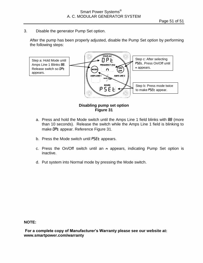
3. Disable the generator Pump Set option.
After the pump has been properly adjusted, disable the Pump Set option by performing the following steps:
Step a: Hold Mode until
Amps Line 1 Blinks .
Release switch so appears.
Step b: Press mode twice
to make appear.
Step c: After selecting
, Press On/Off until
appears.
Disabling pump set option Figure 31
a. Press and hold the Mode switch until the Amps Line 1 field blinks with (more than 10 seconds). Release the switch while the Amps Line 1 field is blinking to
make appear. Reference Figure 31.
b. Press the Mode switch until appears.
c. Press the On/Off switch until an appears, indicating Pump Set option is inactive.
d. Put system into Normal mode by pressing the Mode switch.
NOTE:
For a complete copy of Manufacturer’s Warranty please see our website at: www.smartpower.com/warranty