Embed Size (px)
Citation preview

www.octop lex.com | 866.550.91001
The AC Power Distribution units provide the boat builder with up to 8, 13 or 19 remotely controlled hydraulic-magnetic circuit breakers in one package that can be mounted in virtually any dry areas of the vessel. AC Circuit breakers are available from 1 to 100 amps and are remotely controlled via external solenoids. Each breaker can also be manually actuated. The AC units utilize a 16 bit microprocessor that controls the on/off function of each circuit breaker and provides interfacing to a dual CAN bus network. The AC unit enclosures are made from white, high strength, injection molded plastic that will provide years of protection.
AC Power Distribution Unit
Product Highlights
(8 Position Unit)
• 50 Amps Maximum Capacity
• Remote Actuation of Breakers
• Dual CAN BUS Communication
(13/19 Position Unit)
• 100 Amps Maximum Capacity
• Remote Actuation of Breakers
• Dual CAN BUS Connection/Communication
• Three Phase Power Capability;
120/208VAC or 230/415VAC
PRODUCTS
PART NUMBER 1 DESCRIPTIONNUMBER OF POSITION 2
8 13 19
A3000-X-1 AC Power Distribution Unit - 120V (No Main Breaker) X X X
A3000-X-1M AC Power Distribution Unit - 120V (With Main Breaker) X X X
A3000-X-2 AC Power Distribution Unit - 120/240V (No Main Breaker) X X X
A3000-X-2M AC Power Distribution Unit - 120/240V (With Main Breaker) X X X
A3000-X-3 AC Power Distribution Unit - 120/208V (No Main Breaker) N/A X X
A3000-X-3M AC Power Distribution Unit - 120/208V (With Main Breaker) N/A X X
A3000-X-4 AC Power Distribution Unit - 230V Single Pole (No Main Breaker) X X X
A3000-X-4M AC Power Distribution Unit - 230V Single Pole (With Main Breaker) X X X
A3000-X-5 AC Power Distribution Unit - 230V Double Pole (No Main Breaker) X X X
A3000-X-5M AC Power Distribution Unit - 230V Double Pole (With Main Breaker) X X X
A3000-X-6 AC Power Distribution Unit - 230/415V (No Main Breaker) N/A X X
A3000-X-6M AC Power Distribution Unit - 230/415V (With Main Breaker) N/A X X
Notes: 1. “X” designates the number of breaker positions available for that voltage configuration; see Number of Positions Column
www.octop lex.com | 866.550.91002
N2K Analyzer Configuration Parameters
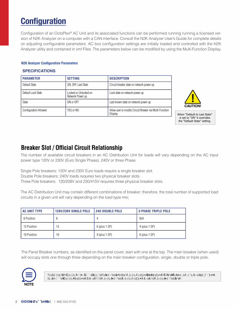
Configuration of an OctoPlex® AC Unit and its associated functions can be performed running running a licensed ver-sion of N2K Analyzer on a computer with a CAN interface. Consult the N2K Analyzer User’s Guide for complete details on adjusting configurable parameters. AC box configuration settings are initially loaded and controlled with the N2K Analyzer utility and contained in xml Files. The parameters below can be modified by using the Multi-Function Display.
Configuration
Breaker Slot / Official Circuit Relationship
SPECIFICATIONS
PARAMETER SETTING DESCRIPTION
Default State ON, OFF, Last State Circuit breaker state on network power up
Default Lock State Locked or Unlocked on Network Power up
Lock state on network power up
State ON or OFF Last known state on network power up
Configuration Allowed YES or NO Allow user to modify Circuit Breaker via Multi-Function Display
The number of available circuit breakers in an AC Distribution Unit for loads will vary depending on the AC input power type 120V or 230V (Euro Single Phase), 240V or three Phase.
Single Pole breakers: 120V and 230V Euro loads require a single breaker slot. Double Pole breakers: 240V loads requires two physical breaker slots.Three Pole breakers: 120/208V and 230/415V requires three physical breaker slots.
The AC Distribution Unit may contain different combinations of breaker; therefore, the total number of supported load circuits in a given unit will vary depending on the load type mix;
The Panel Breaker numbers, as identified on the panel cover, start with one at the top. The main breaker (when used) will occupy slots one through three depending on the main breaker configuration, single, double or triple pole.
AC UNIT TYPE 120V/230V SINGLE POLE 24O DOUBLE POLE 3-PHASE TRIPLE POLE
8 Position 8 4 N/A
13 Position 13 6 (plus 1 SP) 4 (plus 1 SP)
19 Position 19 9 (plus 1 SP) 6 (plus 1 SP)
CAUTION!
When “Default to Last State” is set to “ON” it overrides
the “Default State” setting.
Th e h ig h est AC Break er Rat ing (am p s) sh ou ld b e installed in lowest b reak er p osit ion (i.e. Posit ion 1 , 2 , etc.) to ensu re p rop er load dist r ib u t ion. For exam p le: Break er Posit ions 1 -2 h as 1 0 0 A b reak er installed; b reak er p osit ion 3 h as 70 A b reak er installed; etc.
NOTE

www.octop lex.com | 866.550.91003
If t h e m ain b reak er is exter nal to b ox, t h en loads star t at p osit ion nu m b er 1
NOTE
Breaker Control By Discrete I/O Function
Analog input signals to the System Interface Unit Monitor (SIU) can trigger a Discrete I/O function in the AC processor, which can be used to control the behavior of a Circuit Breaker. Sixteen Discrete I/O’s per AC Unit can be programmed. One Discrete I/O can control multiple breakers up to the unit limit. Discrete I/O functions are configured using N2K Analyzer.
Discrete I/O Description
Off & Lock Turn AC Breaker OFF and Lock in OFF position
Always Turn On Turn AC Breaker ON but does not turn breaker OFF
Always Turn Off Turn AC Breaker OFF but does not turn breaker ON
Toggle On/Off Toggle the state of the AC Breaker
AC Breaker Assignment ConsiderationsThe relationship between the AC units physical breaker positions, the main breaker type & the load breaker assignment (Single Pole, Double Pole, Three Pole) must be taken into consideration & assigned accordingly to the Multi-Function Display AC Unit configuration. The table below illustrates this relationship.
18 Single Pole slots available Double Pole uses 2 positions Single Pole uses 1 positionDouble Pole uses 2 positionsThree Pole uses 3 positions
UNIT BREAKER POSITION
SINGLE POLE
GROUP LINE DOUBLE POLE
GROUP LINE THREE POLE GROUP LINE
1 Main L1 32 L1 Main L1 32 L1 Main L1 32 L12 Load 1 1 L1 Main L2 32 L2 Main L2 32 L23 Load 2 2 L1 Load 1 1 L1 Main L3 32 L34 Load 3 3 L1 Load 2 2 L2 Load 1 1 L15 Load 4 4 L1 Load 3 3 L1 Load 2 2 L26 Load 5 5 L1 Load 4 4 L2 Load 3 3 L37 Load 6 6 L1 Load 5 5 L1 Load 4 4 L18 Load 7 7 L1 Load 6 6 L2 Load 5 5 L29 Load 8 8 L1 Load 7 7 L1 Load 6 6 L310 Load 9 9 L1 Load 8 8 L2 Load 7 7 L111 Load 10 10 L1 Load 9 9 L1 Load 8 8 L212 Load 11 11 L1 Load 10 10 L2 Load 9 9 L313 Load 12 12 L1 Load 11 11 L1 Load 10 10 L114 Load 13 13 L1 Load 12 12 L2 Load 11 11 L215 Load 14 14 L1 Load 13 13 L1 Load 12 12 L316 Load 15 15 L1 Load 14 14 L2 Load 13 13 L117 Load 16 16 L1 Load 15 15 L1 Load 14 14 L218 Load 17 17 L1 Load 16 16 L2 Load 15 15 L3

www.octop lex.com | 866.550.91004
AC No Main Circuit Breaker Installed - Unit Configurations
Line 2
Line 2
Line 1
Line 1Single Phase Dual Line 120/240VAC: Line Bus Bars 1 and 2 are not tied together at the factory, allowing two legs of 120/240VAC to be brought into the unit for single or double pole circuit breaker installation. Breaker position 1 is line 1, breaker position 2 is line 2, and then they alternate.
AC Main Circuit Breaker Installed - Unit Configurations
Single Phase 120VAC or Euro 230VAC: Line Bus Bars 1 and 2 are connected together at the factory using a bus bar jumper.
There are three distinct AC Distribution Unit configurations depending on the type of line input; each requires different hardware options depending on the input line configuration. This configuration must be determined prior to ordering the AC Units.
1. Single Phase 120VAC or Euro 230VAC 2. Single Phase Dual Line 120/240VAC 3. Three Phase 120/208VAC or 230/415VAC
Line 1
Line 2 Single Phase Dual Line 120/240VAC: Line Bus Bars 1 and 2 are not tied together at the factory, allowing two legs of 120/240VAC to be brought into the unit for single or double pole circuit breaker installation.
Line 1
Line 2
Three Phase 120/208VAC or 230/415VAC: Line Bus Bars 1, 2 and 3 are brought into the box separately allowing for single, double or three pole circuit breaker installation.Line 3
Line 2Line 1

www.octop lex.com | 866.550.91005
Mounting
AC Main Connections
These units should be mounted in a location that is accessible for manual/override control and serviceability. These units must be mounted in vertical position only. Installations in horizontal position (flat) with breakers facing up or down can compromise the accuracy of the AC circuit breaker function.
Depending on configuration, connection points are provided for single 120VAC, Single 240VAC (Euro), dual 120/240VAC or three phase (120/208VAC or 230/415VAC) AC line inputs. Bus bars are provided for AC neutral (White or Blue) and grounding (Green or Green-Yellow) conductors. Main feed wires entering the panel are secured to prevent strain using a clamp provided at the opening on the outside of the panel.
Lethal voltages are present inside the AC unit. Verify that all AC power is shut off or disconnected before working inside the unit. Required Torque for each AC breaker terminal screw is 35 inch-lbs. This torque requirement must be applied to all circuit breaker terminal screws, no exceptions. Failure to properly torque each connection may result in damage to the AC Unit or vessel.
The installer is responsible for verifying that the wire gauge used for the main power feed is appropriately sized for the loads being fed from the AC unit. The unit is designed to accept up to #1 gauge wire for the main power feed. All personnel performing installation or maintenance work on the AC Unit will need to have a calibrated torque screwdriver in order to verify proper installation of the circuit breakers and associated connections.
AC Branch Circuit ConnectionsBranch circuit wires enter the AC Power Distribution Unit through the openings at the bottom of the panel. Line conductors are connected to their respective circuit breaker. Neutral and grounding conductors are connected to bus bars provided. Branch wires entering the panel are secured to prevent strain using a screw down “clamp” provided inside of the panel. Circuit breakers are in sequential order from top to bottom. “Tie bars” connecting circuit breaker handles for double and triple pole breakers must be used.
CAN ConnectionsTwo male Micro-C connectors are provided at the bottom left side of the 8 Position or at the top left side of the 13/19 Position unit for connection to the primary and secondary CAN bus via drop cables.
InstallationThe AC Power Distribution Unit is designed to be installed in an environmentally protected, non-explosive area of the vessel. Take precautions to mount the unit in an area that will be away from direct exposure to water, weather and combustible fumes.
HIGH VOLTAGE!
WARNING!
CAUTION!
NOTE
Use the shortest drop length possible when connecting the AC Unit to the CAN backbone. NMEA2000® spec is maximum 6 meters for drop cables.

www.octop lex.com | 866.550.91006
Standard AC Power Distribution Unit Screen LayoutsThe AC Distribution Power Unit screen shows the AC Breaker Label and the current state of the AC Breakers. State of the breaker options include: ON, OFF, Trip, Group Control (ON or OFF), Load Shedding (ON or OFF) or Locked Status (Locked ON or Locked OFF). The user can also scroll forward or backwards to select a specific AC Distribution Power Unit (Example AC Panel #3). For breaker status flags, refer to the appendix page.
OperationDepending on the AC Unit power configuration, 120VAC, Single 240VAC (Euro), dual 120/240VAC or three phase (120/208VAC or 230/415VAC), there are two groups of up to three LED’s visible through the cover of the AC Power Distribution Unit. These LEDs signify that AC power is present inside the unit (“Power In”) and after the Main breaker (“Power Out”). As long as AC power is present, the AC Unit will be recognized by the Multi-Function Display (MFD). When AC power is not present, you will not be able to control the AC circuit breakers.
NOTE
This page can vary between installations, as format is determined and/or customizable by the boat builder or owner.

www.octop lex.com | 866.550.91007
CAN LEDsThe two LEDs labeled “BUS A” and “BUS B” indicate the status of their respective CAN buses, flashing approximately once a second which also serves as a “Heartbeat” indicator from the onboard processor. The possible colors, and their meaning are:
Manual OperationAll AC Circuit Breakers can be controlled directly from the AC Power Distribution Unit (bypassing control from the Multi-Function Display(s)). Follow the instructions below to manually control an AC Circuit Breaker:
Step #1:Remove the cover to the AC Power Distribution Unit by unscrewing the four screws located at each corner of the unit.
Step #2:Operate the toggle lever for the desired circuit breaker. Replace the cover when done.
Lethal voltages are present inside the AC Unit. Verify that all AC power is shut off or disconnected before working inside the unit. When a circuit breaker is turned off manually, it can still be controlled via the Multi-Function Display (MFD). This could present a hazard when performing maintenance on a circuit. It is good practice to “lock” a breaker in the “OFF” position from the Multi-Function Display (MFD) when performing any required maintenance on a circuit. Refer to page 11 for Locking Function.
When manually controlling AC circuit breakers, any time you turn one to the “OFF” position, the system will consider this a tripped breaker and activate the audible alarm if configured to do so. The system sees this as a trip because the system did not command the breaker “OFF”.
AC Processor Protection CircuitThe AC Distribution Unit contains electronics (TVSS) that protect the AC Processor Board from transient voltages and surges; it does not protect the Line Voltages supplied by the AC breakers. The TVSS is mounted inside the AC Distribution Unit near the AC Processor Board. Two (2) keyed connectors connect the TVSS to the input voltage and to the AC Processor Board. A green indicator LED inside the TVSS is lit when all line voltages are present and the TVSS is operating and protecting the AC Processor Board; the case of the TVSS is clear plastic so that the indicator LED can be seen from any angle. The Indicator LED will turn off if the TVSS is at the end of life (provided that all line voltages are present). A TVSS that is at end of life will not compromise the protection of the AC Unit electronics, but could cut off AC power to the electronics if not replaced before exposure to more transients and surges. It is highly recommended to replace the TVSS as soon as possible when end of life is reached.
LED COLOR DESCRIPTION
Flashing Green Bus is healthy
Flashing Orange Bus has transmit or receive data errors, but is still usable
CAUTION!
WARNING!

www.octop lex.com | 866.550.91008
Breaker ReplacementThe AC circuit breakers are not interchangeable like the breakers in the DC Units. If an AC breaker value/rating needs to be changed, the AC Power Distribution Unit will need to be disassembled. Below are the steps required for replacing an AC breaker:
MaintenanceThe AC Unit was designed to require minimal, if any, maintenance. The only field serviceable parts in the AC Unit are the Circuit Breakers and Solenoids.
Step #1:Turn off the main power feeding the AC Power Distribution Unit at the source. Turn all breakers to OFF position. Do not remove the front panel if the LED’s are lit (indicating that AC power is being provided to the panel).
Step #2:Remove front cover by unscrewing the four slotted-head screws located at the corners. Once the screws are removed, the front cover can be lifted straight up and away.
Step #3:Turn the main AC breaker to the OFF position, if configured. Remove sub-cover by unscrewing the four slotted-head screws located at the corners. Once the screws are removed, the sub-cover can be lifted straight up and away.
Step #4 (For 8 Position):Remove the circuit breaker hold down bar by unscrewing the phillips-head screw at the top of the bar. Once the screw is loosened, the hold down bar can be lifted straight up and away.
Step #4 (For 13 & 19 Position):Remove the circuit breaker hold down bar by unscrewing the phillips-head screw at the bottom of the bar. Once the screw is loosened, lift the bottom of the bar straight up and pull the bar out of the slot at the top.
Electric ShockRISK
Hold Down
Bar
Hold Down Bar
1
2
WARNING!
Lethal voltages are present inside the AC Unit. Verify that all AC power is shut off or disconnected before working inside the unit.

www.octop lex.com | 866.550.91009
Step #5:Locate and pull up on the red colored solenoid lock.Remove load terminal connection by unscrewing the load terminal screw
Step #6:Slide the solenoid away from the circuit breaker as shown.
Step #7:Position the Removal Tool and insert hook into circuit breaker slot as shown.
Step #8:Once the Removal Tool hook is inserted in the circuit breaker slot, snap the other side down to secure the connection to the circuit breaker.
Step #9:The circuit breaker can now by removed by pulling the Removal Tool straight up and away from the AC enclosure.
Step #10:Ensure that the replacement circuit breaker actuator is in the OFF position with solenoid installed and the solenoid tab in the locked position. Position breaker above slot, push straight down until the circuit breaker is in its full seated position.
Note: The Removal Tool is only used to remove the circuit breaker. You cannot install the breaker with the Removal Tool.
Solenoid Lock
Removal Tool
Breaker Replacement (continued)
WARNING!
Make sure main power feeding the AC Power Distribution Unit at the source is

www.octop lex.com | 866.550.910010
Step #11:Install load wire ring terminal to circuit breaker as shown.
Step #12 (For 8 Position):Re-Install the circuit breaker hold down bar by placing it as shown and screwing the phillips-head screw at the top of the bar.
Step #12 (For 13 & 19 Position):Re-Install the circuit breaker hold down bar by pushing the top of the bar into the slot of the unit and then pushing the bottom of the bar down. Screw the phillips-head screw at the bottom of the bar.
Hold Down Bar
Hold Down Bar
2
1
Step #14:Re-Install the front cover by screwing the four slotted-head screws located at the corners. Turn the main power feeding the AC Power Distribution Unit at the source to the ON position.
Step #13:Re-Install the sub-cover by screwing the four slotted-head screws located at the corners. Turn the main AC breaker to the ON position.
Breaker Replacement (continued)
WARNING!
Required Torque for each AC breaker terminal screw is 35 inch-lbs. This torque requirement must be applied to all circuit breaker
terminal screws, no exceptions. Failure to properly torque each connection may result in damage to the AC Unit or vessel.
CAUTION!
All personnel performing installation or maintenance work on the AC Unit will need to have a calibrated torque screwdriver in order to
verify proper installation of the circuit breakers and associated connections.

www.octop lex.com | 866.550.910011
Step #4:Locate the input and output connectors of the TVSS and pull them apart.
Step #5:Remove the two (2) screws holding the TVSS to the AC Unit case and remove the old TVSS.
AC Processor Protection Circuit Replacement
Step #1:Turn off the main power feeding the AC Power Distribution Unit at the source. Turn all breakers to OFF position. Do not remove the front panel if the LED’s are lit (indicating that AC power is being provided to the panel).
Step #2:Remove front cover by unscrewing the four slotted-head screws located at the corners. Once the screws are removed, the front cover can be lifted straight up and away.
Step #3:Turn the main AC breaker to the OFF position, if configured. Remove sub-cover by unscrewing the four slotted-head screws located at the corners. Once the screws are removed, the sub-cover can be lifted straight up and away.
Electric ShockRISK

www.octop lex.com | 866.550.910012
Step #6:Install new TVSS connecting the input and output connectors and reinstall the two (2) screws.
Step #8:Re-Install the front cover by screwing the four slotted-head screws located at the corners. Turn the main power feeding the AC Power Distribution Unit at the source to the ON position.
Step #7:Re-Install the sub-cover by screwing the four slotted-head screws located at the corners. Turn the main AC breaker to the ON position.
AC Processor Protection Circuit Replacement (continued)
CAUTION!
All personnel performing installation or maintenance work on the AC Unit will need to have a calibrated torque screwdriver in order to verify proper installation of the circuit breakers and associated connections.

www.octop lex.com | 866.550.910013
Tech Specs
ELECTRICAL
Operating Voltage, Power Input
(Single Phase) 120VAC; Euro 230VAC
(Double Phase) 120/240VAC
(Three Phase) 120/208VAC; 230/415 VAC
CAN Bus Operating Voltage 9 VDC – 16 VDC, 15 VDC Nominal
MECHANICAL
Dimensions 12.36” X 11.63” X 4.98”
Dimensions 20.66” X 13.39” X 4.98”
CAN Bus Connectors Two (2) Micro-C Male
CAN A Bus LED Indicator Green / Red
CAN B Bus LED Indicator Green / Red
MAIN Power In Indicator Green (3)
MAIN Power Out Indicator Green (3)
8 Position Mounting 4 each
19 Position Mounting 10 each
ENVIRONMENTAL
Radiated, RF Field Immunity IEC-61000-4-3
Electrical Fast Transient/Burst Immunity
IEC 61000-4-4
Voltage Surge Immunity IEC 61000-4-5
Conducted, Immunity IEC 61000-4-6
Conducted Emissions IEC 60945
Voltage Variation Immunity IEC 61000-4-11
Conducted LF Immunity IEC 61000-4-16
ESD Immunity IEC-61000-4-2
Insulation Resistance IEC-60092-504
Operating Temperature -40°C to +55°C
Storage Temperature -40°C to +55°C
Vibration IEC-60068-2-6 Test Fc
Temperature Cycle IEC 60945
Humidity IEC-60068-2-30 Test Db
Corrosion IEC 60945
CERTIFICATIONS
NMEA 2000 Category B
Lloyd’s Register Lloyd’s Type Approved, Test Specification #1, Env 2

www.octop lex.com | 866.550.910014
8 Circuit AC Power Distribution Unit A3000-08-[ ]
Dimensional Specs in. [mm]
12.36[313.90]
12.29[312.20]
11.63 [295.30]
4.54 [115.40]
4.98 [126.50]
0.85 [21.60]
0.205 [5.21]
0.28[7.00]
2.68[68.10]
2.55[64.80]
1.28[32.40]
1.18 [29.90]
3.63 [92.20]0.61
[15.40]
3.36[85.20]
1.50[38.10]
1.43[36.20]
SEE DETAIL A2.34
[59.436]
2.06[52.324]
4.03[102.36]
5.54[140.71]
10.63[270.00]
0.84[21.34]
3.32[84.33]
6.24[158.50]
2.06[52.32]
Ø 0.22 [5.59]
DETAIL A
Mounting Dimensions shown in Blue represented underneath cover.
Ø 0.44 [11.18]
0.31[7.87]
0.22[5.59]

www.octop lex.com | 866.550.910015
13 Circuit AC Power Distribution Unit A3000-13-[ ]
Dimensional Specs in. [mm]
13.39 [340.00]12.50 [317.58]
12.70 [322.58]
15.18 [385.60]
16.13 [409.77]6.35
[161.29]
10.13 [257.30]
11.625 [295.28]
5.105[129.67]
www.octop lex.com | 866.550.910016
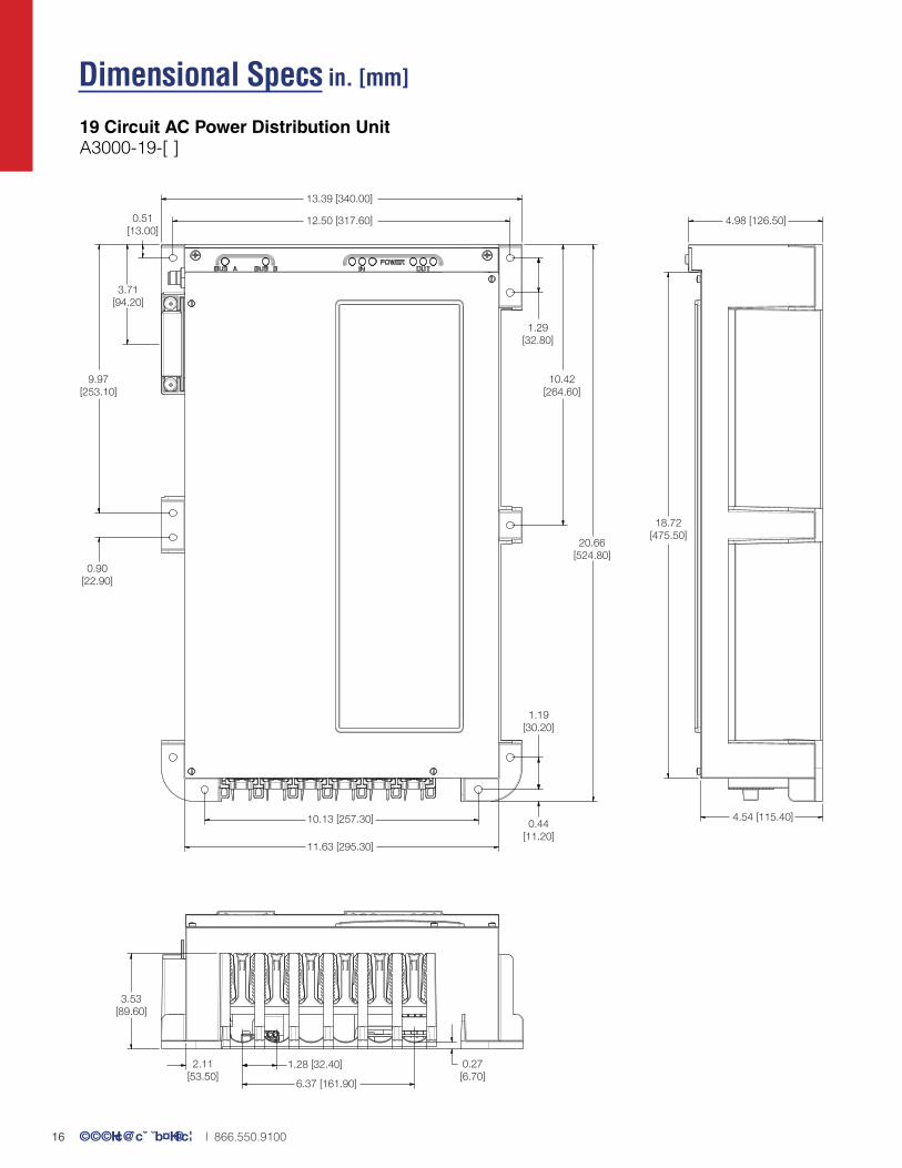
19 Circuit AC Power Distribution Unit A3000-19-[ ]
13.39 [340.00]
12.50 [317.60] 4.98 [126.50]0.51[13.00]
3.71[94.20]
9.97[253.10]
1.29[32.80]
10.42[264.60]
20.66[524.80]
0.90[22.90]
1.19[30.20]
0.44[11.20]
11.63 [295.30]
10.13 [257.30]
18.72[475.50]
4.54 [115.40]
0.27[6.70]
6.37 [161.90]
1.28 [32.40]2.11[53.50]
3.53[89.60]
Dimensional Specs in. [mm]