Embed Size (px)
Citation preview
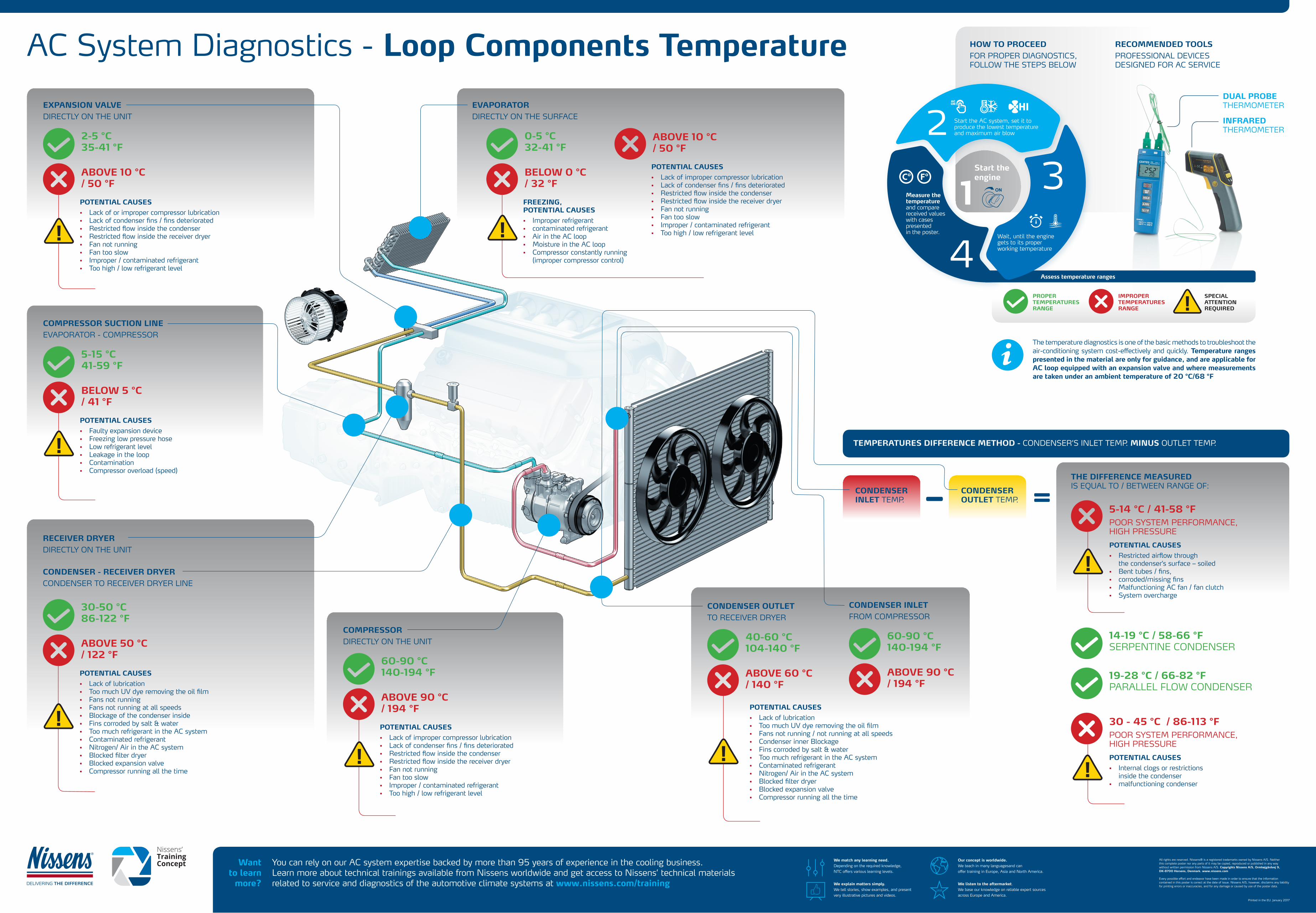
EXPANSION VALVE DIRECTLY ON THE UNIT
EVAPORATOR DIRECTLY ON THE SURFACE
RECEIVER DRYER DIRECTLY ON THE UNIT
You can rely on our AC system expertise backed by more than 95 years of experience in the cooling business.Learn more about technical trainings available from Nissens worldwide and get access to Nissens’ technical materials related to service and diagnostics of the automotive climate systems at www.nissens.com/training
All rights are reserved. Nissens® is a registered trademarks owned by Nissens A/S. Neitherthis complete poster nor any parts of it may be copied, reproduced or published in any waywithout written permission from Nissens A/S. Copyrights Nissens A/S, Ormhøjgårdvej 9, DK-8700 Horsens, Denmark. www.nissens.com
Every possible effort and endeavor have been made in order to ensure that the informationcontained in this poster is correct at the date of issue. Nissens A/S, however, disclaims any liability for printing errors or inaccuracies, and for any damage or caused by use of the poster data.
Printed in the EU. January 2017
Wantto learn
more?
CONDENSER - RECEIVER DRYER CONDENSER TO RECEIVER DRYER LINE
COMPRESSOR SUCTION LINE EVAPORATOR - COMPRESSOR
COMPRESSOR DIRECTLY ON THE UNIT
CONDENSER INLET FROM COMPRESSOR
CONDENSER OUTLET TO RECEIVER DRYER
THE DIFFERENCE MEASURED IS EQUAL TO / BETWEEN RANGE OF:
CONDENSER INLET TEMP.
CONDENSER OUTLET TEMP.
TEMPERATURES DIFFERENCE METHOD - CONDENSER’S INLET TEMP. MINUS OUTLET TEMP.
2-5 °C 35-41 °F
0-5 °C32-41 °F
30-50 °C 86-122 °F
5-15 °C41-59 °F
60-90 °C140-194 °F
60-90 °C140-194 °F
40-60 °C104-140 °F
14-19 °C / 58-66 °FSERPENTINE CONDENSER
19-28 °C / 66-82 °FPARALLEL FLOW CONDENSER
ABOVE 10 °C / 50 °F
BELOW 0 °C / 32 °F
ABOVE 10 °C / 50 °F
ABOVE 50 °C / 122 °F
BELOW 5 °C / 41 °F
ABOVE 90 °C/ 194 °F
ABOVE 90 °C/ 194 °F
ABOVE 60 °C/ 140 °F
5-14 °C / 41-58 °FPOOR SYSTEM PERFORMANCE, HIGH PRESSURE
30 - 45 °C / 86-113 °FPOOR SYSTEM PERFORMANCE, HIGH PRESSURE
POTENTIAL CAUSES
• Lack of or improper compressor lubrication• Lack of condenser fins / fins deteriorated • Restricted flow inside the condenser• Restricted flow inside the receiver dryer• Fan not running• Fan too slow• Improper / contaminated refrigerant• Too high / low refrigerant level
FREEZING, POTENTIAL CAUSES
• Improper refrigerant• contaminated refrigerant• Air in the AC loop• Moisture in the AC loop• Compressor constantly running (improper compressor control)
POTENTIAL CAUSES
• Lack of improper compressor lubrication• Lack of condenser fins / fins deteriorated • Restricted flow inside the condenser• Restricted flow inside the receiver dryer• Fan not running• Fan too slow• Improper / contaminated refrigerant• Too high / low refrigerant level
POTENTIAL CAUSES
• Lack of lubrication• Too much UV dye removing the oil film• Fans not running• Fans not running at all speeds• Blockage of the condenser inside• Fins corroded by salt & water• Too much refrigerant in the AC system• Contaminated refrigerant• Nitrogen/ Air in the AC system• Blocked filter dryer• Blocked expansion valve• Compressor running all the time
POTENTIAL CAUSES
• Faulty expansion device• Freezing low pressure hose• Low refrigerant level• Leakage in the loop• Contamination• Compressor overload (speed)
POTENTIAL CAUSES
• Lack of improper compressor lubrication• Lack of condenser fins / fins deteriorated • Restricted flow inside the condenser• Restricted flow inside the receiver dryer• Fan not running• Fan too slow• Improper / contaminated refrigerant• Too high / low refrigerant level
POTENTIAL CAUSES
• Lack of lubrication• Too much UV dye removing the oil film• Fans not running / not running at all speeds• Condenser inner Blockage• Fins corroded by salt & water• Too much refrigerant in the AC system• Contaminated refrigerant• Nitrogen/ Air in the AC system• Blocked filter dryer• Blocked expansion valve• Compressor running all the time
POTENTIAL CAUSES
• Restricted airflow through the condenser’s surface – soiled• Bent tubes / fins, • corroded/missing fins• Malfunctioning AC fan / fan clutch• System overcharge
POTENTIAL CAUSES
• Internal clogs or restrictions inside the condenser• malfunctioning condenser
1
2
3
4
Start theengine
Start the AC system, set it to produce the lowest temperature and maximum air blow
Wait, until the engine gets to its proper working temperature
Measure thetemperature and comparereceived valueswith cases presentedin the poster.
HOW TO PROCEED FOR PROPER DIAGNOSTICS, FOLLOW THE STEPS BELOW
Assess temperature ranges
PROPERTEMPERATURESRANGE
IMPROPERTEMPERATURESRANGE
SPECIALATTENTIONREQUIRED
AC System Diagnostics - Loop Components Temperature RECOMMENDED TOOLS PROFESSIONAL DEVICES DESIGNED FOR AC SERVICE
DUAL PROBETHERMOMETER
INFRAREDTHERMOMETER
The temperature diagnostics is one of the basic methods to troubleshoot the air-conditioning system cost-effectively and quickly. Temperature ranges presented in the material are only for guidance, and are applicable for AC loop equipped with an expansion valve and where measurements are taken under an ambient temperature of 20 °C/68 °F
We match any learning need. Depending on the required knowledge, NTC offers various learning levels.
We explain matters simply. We tell stories, show examples, and present very illustrative pictures and videos.
Our concept is worldwide.We teach in many languagesand can offer training in Europe, Asia and North America.
We listen to the aftermarket. We base our knowledge on reliable expert sources across Europe and America.