Embed Size (px)
Citation preview
AD
HESIV
ES
www.powers.com 1
TECH MAN
UAL – ADHESIVES ©2016 PO
WERS VO
LUME 1 – REV. M
GENERAL INFORMATION
SECTION CONTENTS
General Information ......................1Reference data (ASD) ....................2Strength Design (SD) .....................7Installation Instructions (Solid Base Materials) .................22Installation Instructions (Hollow Base Materials)..............23Reference Tables For Installation ....................................24Ordering Information ..................25
AC100+ GOLD COAXIAL CARTRIDGE WITH MIXING NOZZLE
AC100+ GOLD DUAL CARTRIDGE WITH MIXING NOZZLE AND EXTENSION
PACKAGINGCoaxial Cartridge
• 10 fl . oz. (280 ml or 17.1 in3)Dual (side-by-side Cartridge)
• 12 fl . oz. (345 ml or 21.0 in3)• 28 fl . oz. (825 ml or 50.3 in3)
STORAGE LIFE & CONDITIONSEighteen months in a dry, dark environment with temperature ranging from 32°F and 86°F (-0°C to 30°C)
ANCHOR SIZE RANGE (TYP.)• 3/8" to 1-1/4" diameter rod• No. 3 to No. 10 rebar
SUITABLE BASE MATERIALS• Normal-weight Concrete• Grouted concrete masonry (CMU)• Hollow concrete masonry (CMU)• Brick masonry
PERMISSIBLE INSTALLATION CONDITIONS (ADHESIVE)• Dry concrete• Water-saturated concrete (wet)• Water-fi lled holes (fl ooded)
GENERAL INFORMATION
AC100+ GOLD®
Vinylester Injection Adhesive Anchoring System
PRODUCT DESCRIPTION
The AC100+ Gold is a two-component vinylester adhesive anchoring system. The system includes injection adhesive in plastic cartridges, mixing nozzles, dispensing tools and hole cleaning equipment. The AC100+ Gold is designed for bonding threaded rod and reinforcing bar elements into drilled holes in concrete and masonry base materials.
GENERAL APPLICATIONS AND USES
• Bonding threaded rod and reinforcing bar into hardened concrete and masonry
• Evaluated for use in dry and water-saturated concrete (including water fi lled holes)
• Suitable to resist loads in cracked or uncracked concrete base materials
• Can be installed in a wide range of base material temperatures; qualifi ed for structural applications in concrete as low as 14ºF
• Qualifi ed for seismic (earthquake) and wind loading
FEATURES AND BENEFITS
+ Designed for use with threaded rod and reinforcing bar hardware elements
+ Consistent performance in low and high strength concrete
+ Evaluated and recognized for freeze/thaw performance (interior and exterior applications)
+ Evaluated and recognized for a range of embedments
+ Versatile low odor formula with quick cure time
+ Evaluated and recognized for long term and short term loading (see performance tables)
+ Mixing nozzles proportion adhesive and provide simple delivery method into drilled holes
+ Cartridge design allows for multiple uses using extra mixing nozzles
APPROVALS AND LISTINGS
• International Code Council, Evaluation Service (ICC-ES) ESR-2582 for concrete
• International Code Council, Evaluation Service (ICC-ES) ESR-3200 for masonry
• Code compliant with the 2015 IRC, 2015 IBC, 2012 IBC, 2012 IRC, 2009 IBC, and 2009 IRC.
• Tested in accordance with ASTM E488 / ACI 355.4 and ICC-ES AC308 for use in structural concrete with ACI 318-14 Chapter 17 or ACI 318-11/08 Appendix D.
• Compliant with NSF/ANSI Standard 61 for drinking water system components – health effects; meets requirements for materials in contact with potable water and water treatment
• Conforms to requirements of ASTM C 881 and AASHTO M235, Types I, II, IV and V, Grade 3, Classes A & B (meets Type III with exception of elongation)
• Department of Transportation listings – see www.powers.com or contact transportation agency
GUIDE SPECIFICATIONS
CSI Divisions: 03 16 00 - Concrete Anchors, 04 05 19.16 - Masonry Anchors and 05 05 19 - Post-Installed Concrete Anchors. Adhesive anchoring system shall be AC100+ Gold as supplied by Powers Fasteners Inc., Towson, MD. Anchors shall be installed in accordance with published instructions and requirements of the Authority Having Jurisdiction.
QU
A L I F I C A T I ON
SEIS
M IC REGION
CR
AC
K E D C O N C RE
TE
TE
NS ION ZONE
code listedICC-ES ESR-2582
CONCRETE
This Product Available In
®
Powers Design AssistReal-Time Anchor Design Softwarewww.powersdesignassist.com

www.powers.com 2
AD
HESIV
ES
REFERENCE DATA (ASD)
TECH
MAN
UAL
– AD
HESI
VES
©20
16 P
OW
ERS
VO
LUM
E 1
– R
EV. M
REFERENCE DATA (ASD)
Allowable Stress Design (ASD) Installation Table for AC100+ Gold (Solid Concrete Base Materials)
Dimension/Property Notation Units Nominal Anchor Size
Threaded rod - - 3/8" 1/2" - 5/8" 3/4’" 7/8" 1" - 1-1/4" -
Reinforcing bar - - #3 - #4 #5 #6 #7 #8 #9 - #10
Nominal anchor diameter d in.(mm)
0.375(9.5)
0.500(12.7)
0.625(15.9)
0.750(19.1)
0.875(22.2)
1.000(25.4)
1.125(28.6)
1.250(31.8)
1.250(31.8)
Nominal diameter of drilled hole dbit in. 7/16ANSI
9/16ANSI
5/8ANSI
11/16or 3/4ANSI
7/8ANSI
1ANSI
1-1/8ANSI
1-3/8ANSI
1-3/8ANSI
1-1/2ANSI
Minimum nominal embedment depth hnomin.
(mm)2-3/8(61)
2-3/4(70)
3-1/8(79)
3-1/2(89)
3-1/2(89)
4(102)
4-1/2(114)
5(127)
5(127)
Maximum torque(only possible after full cure time of adhesive)
A36 or F1554carbon steel rod Tmax
ft.-lb.(N-m)
10(13)
25(34)
50(68)
90(122)
125(169)
165(224) - 280
(379) -
F593 Condition CW stainless steel rod or ASTM A193, Grade B7 carbon steel rod
Tmaxft.-lb.(N-m)
16(22)
33(45)
60(81)
105(142)
125(169)
165(224) - 280
(379) -
Allowable Stress Design (ASD) Installation Table for AC100+ Gold (Hollow Base Material with Screen Tube)Dimension/Property Notation Units Nominal Size - Stainless Steel Nominal Size - Plastic
Threaded Rod - - 1/4" 3/8" 1/2" 5/8" 3/4" 1/4" 3/8" 1/2" 5/8"
Nominal threaded rod diameter d in.(mm)
0.250(6.4)
0.375(9.5)
0.500(12.7)
0.625(15.9)
0.750(19.1)
0.250(6.4)
0.375(9.5)
0.500(12.7)
0.625(15.9)
Nominal screen tube diameter - in. 1/4 3/8 1/2 5/8 3/4 1/4 3/8 1/2 5/8
Nominal diameter of drilled hole dbit in.
(mm)3/8
ANSI1/2
ANSI5/8
ANSI3/4
ANSI7/8
ANSI1/2
ANSI9/16ANSI
3/4ANSI
7/8ANSI
Maximum torque(only possible after full cure time of adhesive) Tmax
ft.-lbf.(N-m)
4(5)
6(8)
10(14)
10(14)
10(14)
4(5)
6(8)
10(14)
10(14)
Detail of Steel Hardware Elements used with Injection Adhesive System
Threaded Rod and Deformed Reinforcing Bar Material Properties
Tmax
hnom
h
c
c
s
d
do(dbit)
Threaded Rodor Rebar
Nomenclature
d = Diameter of anchordbit = Diameter of drilled holeh = Base material thickness
The greater of:[hnom + 1-1/4"] and [hnom + 2dbit]
hnom = Minimum embedment depth
Steel Description (General)
Steel Specification
(ASTM)
Nominal Anchor Size
(inch)
Minimum Yield Strength,
fy (ksi)
Minimum Ultimate Strength,
fu (ksi)
Carbon Rod A 36 or F1554 Grade 36 3/8 through 1-1/4 36.0 58.0
Stainless Rod(Alloy 304 / 316)
F 593,Condition CW
3/8 through 5/8 65.0 100.0
3/4 through 1-1/4 45.0 85.0
High Strength Carbon Rod
A 193Grade B7 3/8 through 1-1/4 105.0 125.0
Grade 60Reinforcing Bar
A 615, A 767, or A 996
3/8 through 1-1/4(#3 through #10) 60.0 90.0
Grade 40Reinforcing Bar A 615 or A 767 3/8 through 1-1/4
(#3 through #6) 40.0 60.0
AD
HESIV
ES
www.powers.com 3
TECH MAN
UAL – ADHESIVES ©2016 PO
WERS VO
LUME 1 – REV. M
REFERENCE DATA (ASD)
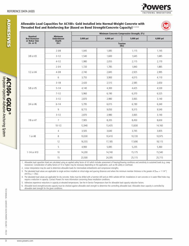
Allowable Load Capacities for AC100+ Gold Installed into Normal-Weight Concrete with Threaded Rod and Reinforcing Bar (Based on Bond Strength/Concrete Capacity)1,2,3,4,5,6
Nominal Rod Diameteror Rebar Size
(in. or #)
MinimumEmbedment
Depth(in.)
Minimum Concrete Compressive Strength, (f’c)
3,000 psi 4,000 psi 5,000 psi 6,000 psi
Tension(lbs)
3/8 or #3
2-3/8 1,045 1,085 1,115 1,145
3-1/2 1,540 1,600 1,645 1,685
4-1/2 1,980 2,055 2,115 2,170
1/2 or #4
2-3/4 1,720 1,785 1,840 1,885
4-3/8 2,740 2,845 2,925 2,995
6 3,755 3,900 4,015 4,110
5/8 or #5
3-1/8 2,420 2,515 2,585 2,650
5-1/4 4,140 4,300 4,425 4,530
7-1/2 5,960 6,190 6,370 6,525
3/4 or #6
3-1/2 2,870 2,980 3,065 3,140
6-1/4 5,795 6,015 6,190 6,340
9 8,715 9,050 9,315 9,540
7/8 or #7
3-1/2 2,870 2,980 3,065 3,140
7 7,905 8,205 8,450 8,650
10-1/2 12,940 13,435 13,830 14,160
1 or #8
4 3,505 3,640 3,745 3,835
8 10,030 10,410 10,720 10,975
12 16,555 17,185 17,690 18,115
1-1/4 or #10
5 4,900 5,085 5,235 5,360
10 14,200 14,740 15,175 15,540
15 23,500 24,395 25,115 25,715
1. Allowable load capacities listed are calculated using an applied safety factor of 4.0 which includes assessment of freezing/thawing conditions and sensitivity to sustained loads (e.g. creep resistance). Consideration of safety factors of 10 or higher may be necessary depending on the application, such as life safety or overhead.
2. Linear interpolation may be used to determine allowable loads for intermediate embedments and compressive strengths.3. The tabulated load values are applicable to single anchors installed at critical edge and spacing distances and where the minimum member thickness is the greater of [hnom + 1-1/4"]
and [hnom + 2dbit].4. The tabulated load values are applicable for dry concrete. Holes must be drilled with a hammer drill and an ANSI carbide drill bit. Installations in wet concrete or in water-filled holes may
require a reduction in capacity. Contact Powers for more information concerning these installation conditions.5. Adhesives experience reductions in capacity at elevated temperatures. See the In-Service Temperature chart for allowable load capacity reduction factors.6. Allowable bond strength/concrete capacity must be checked against allowable steel strength to determine the controlling allowable load. Allowable shear capacity is controlled by
allowable steel strength for the given conditions.

www.powers.com 4
AD
HESIV
ES
REFERENCE DATA (ASD)
TECH
MAN
UAL
– AD
HESI
VES
©20
16 P
OW
ERS
VO
LUM
E 1
– R
EV. M
Allowable Load Capacities for AC100+ Gold Installed into Normal-Weight Concrete with Threaded Rod and Reinforcing Bar (Based on Steel Strength)1,2,3
Nominal Rod
Diameter or Rebar Size (in.
or #)
Steel Elements - Threaded Rod and Reinforcing Bar
A36 or F1554, Grade 36 A 193, Grade B7 or F1554, Grade 105 F 593, CW (SS) Grade 60 Rebar Grade 40 Rebar
Tensionlbs
(kN)
Shearlbs
(kN)
Tensionlbs
(kN)
Shearlbs
(kN)
Tensionlbs
(kN)
Shearlbs
(kN)
Tensionlbs
(kN)
Shearlbs
(kN)
Tensionlbs
(kN)
Shearlbs
(kN)
3/8 or #3 2,115(9.4)
1,090(4.8)
4,555(20.3)
2,345(10.4)
3,645(16.2)
1,880(8.4)
3,280(14.6)
1,690(7.5)
2,185(9.7)
1,125(5.0)
1/2 or #4 3,760(16.7)
1,935(8.6)
8,100(36.0)
4,170(18.5)
6,480(28.8)
3,340(14.9)
5,830(25.9)
3,005(13.4)
3,890(17.3)
2,005(8.9)
5/8 or #5 5,870(26.1)
3,025(13.5)
12,655(56.3)
6,520(29.0)
10,125(45.0)
5,215(23.2)
9,110(40.5)
4,695(20.9)
6,075(27.0)
3,130(13.9)
3/4 or #6 8,455(37.6)
4,355(19.4)
18,225(81.1)
9,390(41.8)
12,390(55.1)
6,385(28.4)
13,120(58.4)
6,760(30.1)
8,745(38.9)
4,505(20.0)
7/8 or #7 11,510(51.2)
5,930(26.4)
24,805(110.3)
12,780(56.8)
16,865(75.0)
8,690(38.7)
17,860(79.4)
9,200(40.9)
11,905(53.0)
6,135(27.3)
1 or #8 15,035(66.9)
7,745(34.5)
32,400(144.1)
16,690(74.2)
22,030(98.0)
11,350(50.5)
23,325(103.8)
12,015(53.4)
15,550(69.2)
8,010(35.6)
#9 - - - - - - 29,680(132.0)
15,290(68.0)
19,785(88.0)
10,195(45.3)
1-1/4 23,490(104.5)
12,100(53.8)
50,620(225.2)
26,080(116.0)
34,425(153.1)
17,735(78.9) - - - -
#10 - - - - - - 37,625(167.4)
19,380(86.2)
25,080(111.6)
12,920(57.5)
AISC defined steel strength (ASD): Tensile = 0.33 • Fu • Anom, Shear = 0.17 • Fu • Anom
1. Allowable load capacities listed are calculated for the steel element type. Consideration of applying additional safety factors may be necessary depending on the application, such as life safety or overhead.
2. Allowable bond strength/concrete capacity must be checked against allowable steel strength to determine the controlling allowable load.3. Allowable shear capacity is controlled by steel strength for the given conditions described on the previous page.
Load-Temperature Reduction CurveConcrete Base Materials
Load-Temperature Reduction CurveMasonry Units
0%
10%
20%
30%
40%
50%
60%
70%
80%
90%
100%
Base Material Temperature, ºF
% o
f Allo
wab
le L
oad
Bond
Str
engt
h @
70º
F
30ºF 45ºF 60ºF 75ºF 90ºF 105ºF 120ºF 135ºF 150ºF 165ºF15ºF 180ºF0%
10%
20%
30%
40%
50%
60%
70%
80%
90%
100%
Base Material Temperature, ºF
% o
f Allo
wab
le L
oad
Bond
Str
engt
h @
70º
F
30ºF 45ºF 60ºF 75ºF 90ºF 105ºF 120ºF 135ºF 150ºF 165ºF15ºF 180ºF

AD
HESIV
ES
www.powers.com 5
TECH MAN
UAL – ADHESIVES ©2016 PO
WERS VO
LUME 1 – REV. M
REFERENCE DATA (ASD)
Allowable Load Capacities for Threaded Rod Installed with AC100+ Gold into Grout Filled Concrete Masonry (Based on Bond Strength/Masonry Strength)1,2,3,7,9,12,17
AnchorDiameter
d(inch)
Minimum Embedment
hnom(inch)
Critical Spacing Distance
scr(inch)
Minimum Edge Distance
cmin(inch)
Minimum End Distance
cmin(inch)
Tension Load (lbs)
Direction of Shear Loading
Shear Load(lbs)
Anchor Installed Into Grouted Masonry Wall Faces4,5,6,8,10,11,13
3/8 3
6 3 3 615 Towards Edge/End 2756 3 3 615 Away From Edge/End 3406 3 4 73517 Any 49017
6 12 12 96017 Any 85517
1/2 4
8 3 3 720 Towards Edge/End 4298 3 3 720 Away From Edge/End 13208 4 4 98517 Any 65517
8 12 12 960 Towards Edge/End 14308 12 12 960 Away From Edge/End 17608 7-3/4 (Bed Joint) 3 935 Load To Edge 460
5/8 5
10 3 3 712 Towards Edge/End 45910 3 3 712 Away From Edge/End 141010 12 12 1095 Towards Edge/End 153010 12 12 1095 Away From Edge/End 188010 7-3/4 (Bed Joint) 3 103017 Load To Edge 59017
3/4 6
12 4 4 754 Towards Edge/End 62812 4 4 754 Away From Edge/End 144812 12 12 1160 Towards Edge/End 157012 12 12 1160 Away From Edge/End 193012 7-3/4 (Bed Joint) 4 945 Load To Edge 565
Anchor Installed Into Tops of Grouted Masonry Walls14,15
Anchor Diameter
d(inch)
Minimum Embedment
hnom(inch)
Minimum Spacing Distance
Minimum Edge Distance
cmin(inch)
Minimum End Distance
cmin(inch)
Tension Load (lbs)
Direction of Shear Loading
Shear Load(lbs)
1/2
2.75 1 anchor per cell 1.75 4 59517 Any 30017
4 1 anchor per cell 1.75 3 520 Load To Edge 1904 1 anchor per cell 1.75 3 520 Load To End 30010 1 anchor per block16 1.75 10.5 1670 Load To Edge 19010 1 anchor per block16 1.75 10.5 1670 Load To End 300
5/8
5 1 anchor per cell 1.75 3 745 Load To Edge 2405 1 anchor per cell 1.75 3 745 Load To End 300
12.5 1 anchor per block16 2.75 10.5 2095 Load To Edge 24012.5 1 anchor per block16 2.75 10.5 2095 Load To End 300
3/46 1 anchor per cell 2.75 4 1260 Load To Edge 4106 1 anchor per cell 2.75 4 1260 Load To End 490
1. Tabulated load values are for anchors installed in nominal 8-inch wide (203 mm) Grade N, Type II, lightweight, medium-weight or normal-weight grout filled concrete masonry units with a minimum masonry strength, f’m, of 1,500 psi (10.3 MPa) conforming to ASTM C 90. If the specified compressive strength of the masonry, f’m, is 2,000 psi (13.8 MPa) minimum the tabulated values may be increased by 4 percent (multiplied by 1.04).
2. Allowable bond or masonry strengths in tension and shear are calculated using a safety factor of 5.0 and must be checked against the allowable tension and shear capacities for threaded rod based on steel strength to determine the controlling factor. See allowable load table based on steel strength.
3. Embedment is measured from the outside surface of the concrete masonry unit to the embedded end of the anchor.4. Anchors may be installed in the grouted cells, cell webs and bed joints not closer than 1-1/2-inch from the vertical mortar joint (head joint) provided the minimum edge and end distances
are maintained. Anchors may be placed in the head joint if the vertical joint is mortared full-depth.5. A maximum of two anchors may be installed in a single masonry cell in accordance with the spacing and edge or end distance requirements.6. The critical spacing, scr, for use with the anchor values shown in this table is 16 anchor diameters. The critical spacing, scr, distance is the distance where the full load values in the table
may be used. The minimum spacing distance, smin, is the minimum anchor spacing for which values are available and installation is permitted. For 3/8-inch diameter anchors, the spacing may be reduced to 8 anchor diameters when using a tension reduction factor of 0.70 and a shear reduction factor of 0.45. For ½ - and 5/8 – inch diameter anchors, the spacing may be reduced to 8 anchor diameters when using a tension reduction factor of 0.85 and a shear reduction factor of 0.45. For 3/4-inch diameter anchors, the spacing may be reduced to 8 anchor diameters when using a tension reduction factor of 1.00 and a shear reduction factor of 0.45.
7. Spacing distance is measured from the centerline to centerline between two anchors.8. The critical edge or end distance, ccr, is the distance where full load values in the table may be used. The minimum edge or end distance, cmin, is the minimum distance for which values
are available and installation is permitted.9. Edge or end distance is measured from anchor centerline to the closest unrestrained edge.10. Linear interpolation of load values between the minimum spacing, smin, and critical spacing, scr, distances and between minimum edge or end distance, cmin, and critical edge or end
distance, ccr, is permitted.11. The tabulated values are applicable for anchors in the ends of grout-filled concrete masonry units where minimum edge and end distances are maintained.12. The tabulated values must be adjusted for increased in-service base material temperatures in accordance with the In-Service Temperature chart, as applicable.13. Concrete masonry width (wall thickness) must be equal to or greater than 1.5 times the anchor embedment depth (e.g. 3/8-inch and 1/2-inch diameter anchors are permitted in nominally
6-inch-thick concrete masonry). The 5/8-inch and 3/4-inch diameter anchors must be installed in minimum nominally 8-inch-thck concrete masonry. 14. Anchors must be installed into the grouted cell; anchors are not permitted to be installed in a head joint, flange or wen of the concrete masonry unit.15. Allowable shear loads parallel or perpendicular to the edge of a masonry wall may be applied in or out of plane.16. Anchors with minimum spacing distance of one anchor per block may not be installed in adjacent cells (i.e. one cell must separate the anchor locations).17. Tabulated values not included in ESR-3200.
www.powers.com 6
AD
HESIV
ES
REFERENCE DATA (ASD)
TECH
MAN
UAL
– AD
HESI
VES
©20
16 P
OW
ERS
VO
LUM
E 1
– R
EV. M
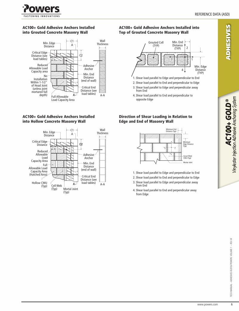
AC100+ Gold Adhesive Anchors Installed into Grouted Concrete Masonry Wall
AC100+ Gold Adhesive Anchors Installed into Top of Grouted Concrete Masonry Wall
AC100+ Gold adhesive anchors installed into grouted concrete masonry wall
Wall Thickness
C2
Min. Edge Distance
Critical Edge Distance (see
load tables)
Reduced Allowable Load
Capacity areaNo
Installation Within 1-1/2" of Head Joint (unless joint
mortared full depth)
Adhesive Anchor
Full Allowable Load Capacity Area
Critical End Distance (see load tables)
Min. End Distance
(end of wall)
A
C1A
A-A
AC100+ Gold Adhesive Anchors Installed into the Top of Grouted Concrete Masonry Wall
Min. End Distance
(TYP)
Min. Edge Distance
(TYP)
Grouted Cell(TYP)
1
2
3
4
1. Shear load parallel to Edge and perpendicular to End
2. Shear load parallel to End and perpendicular to Edge
3. Shear load parallel to Edge and perpendicular away from End
4. Shear load parallel to End and perpendicular to opposite Edge
AC100+ Gold Adhesive Anchors Installed into Hollow Concrete Masonry Wall
Direction of Shear Loading in Relation to Edge and End of Masonry Wall
AC100+ Gold Adhesive Anchors Installed into Hollow Concrete Masonry Wall
Wall Thickness
C2
Min. Edge Distance
Critical Edge Distance
Reduced Allowable
Load Capacity Area
Full Allowable Load
Capacity Area(Hatched Area)
Adhesive Anchor
Cell Web (Typ)
Critical End Distance (see load tables)
Min. End Distance
(end of wall)
A
C1A
A-AHollow CMU (Typ)
Mortal Joint (Typ)
AC100+ Gold Direction of Shead Loading in Relation to Edge and End of Masonry Wall
1. Shear load parallel to Edge and perpendicular to End
2. Shear load parallel to End and perpendicular to Edge
3. Shear load parallel to Edge and perpendicular away from End
4. Shear load parallel to End and perpendicular away from Edge
Minimum End Distance (Typ)
Minimum Edge Distance (Typ)
Grout Filled CMU (Typ)
Mortar Joint
1
2
3
4

AD
HESIV
ES
www.powers.com 7
TECH MAN
UAL – ADHESIVES ©2016 PO
WERS VO
LUME 1 – REV. M
REFERENCE DATA (ASD)
Allowable Load Capacities for Threaded Rod Installed with AC100+ Gold Into Hollow Concrete Masonry Walls with Stainless Steel and Plastic Screen Tubes1,2,3,4,5,6,7,8,9,10,11,12,13
AnchorDiameter
d(inch)
Screen Tube(type)
Minimum Embedment
hnom(inch)
Critical Spacing Distance
scr(inch)
Minimum Edge
Distancecmin(inch)
Minimum End Distance
cmin(inch)
Allowable Load
Tension Load (lbs)
Direction of Shear Loading
Shear Load(lbs)
1/4 (6.4)
Stainless Steel
1-1/4(31.8)
4(101.6)
1-1/2(38.1)
1-1/2(38.1)
280(1.2) Towards Edge/End 140
(0.6)1-1/4(31.8)
4(101.6)
3(76.2)
3(76.2)
350(1.6) Towards Edge/End 275
(1.2)1-1/4(31.8)
4(101.6)
1-1/2(38.1)
1-1/2(38.1)
280(1.2) Away From Edge/End 235
(1.0)1-1/4(31.8)
4(101.6)
3(76.2)
3(76.2)
350(1.6) Away From Edge/End 465
(2.1)
Plastic14 1-1/4(31.8)
1 anchor per cell
3(76.2)
3(76.2)
140(0.6) Towards Edge/End 235
(1.0)
3/8 (9.5)
Stainless Steel
1-1/4(31.8)
6(152.4)
1-7/8(47.6)
1-7/8(47.6)
320(1.4) Towards Edge/End 145
(0.6)1-1/4(31.8)
6(152.4)
3-3/4(95.3)
3-3/4(95.3)
400(1.8) Towards Edge/End 290
(1.3)1-1/4(31.8)
6(152.4)
1-7/8(47.6)
1-7/8(47.6)
320(1.4) Away From Edge/End 245
(1.1)1-1/4(31.8)
6(152.4)
3-3/4(95.3)
3-3/4(95.3)
400(1.8) Away From Edge/End 490
(2.2)
Plastic 1-1/4(31.8)
1 anchor per cell
3(76.2)
3(76.2)
140(0.6) Towards Edge/End 235
(1.0)
1/2 (12.7)
Stainless Steel
1-1/4(31.8)
8(203.2)
3-3/4(95.3)
3-3/4(95.3)
380(1.7) Towards Edge/End 215
(1.0)1-1/4(31.8)
8(203.2)
11-1/4(285.8)
11-1/4(285.8)
400(1.8) Towards Edge/End 430
(1.9)1-1/4(31.8)
8(203.2)
3-3/4(95.3)
3-3/4(95.3)
380(1.7) Away From Edge/End 365
(1.6)1-1/4(31.8)
8(203.2)
11-1/4(285.8)
11-1/4(285.8)
400(1.8) Away From Edge/End 730
(3.2)
Plastic 1-1/4(31.8)
1 anchor per cell
3(76.2)
3(76.2)
150(0.7) Towards Edge/End 215
(1.0)
5/8 (15.9)
Stainless Steel
1-1/4(31.8)
8(203.2)
3-3/4(95.3)
3-3/4(95.3)
380(1.7) Towards Edge/End 215
(1.0)1-1/4(31.8)
8(203.2)
11-1/4(285.8)
11-1/4(285.8)
400(1.8) Towards Edge/End 430
(1.9)1-1/4(31.8)
8(203.2)
3-3/4(95.3)
3-3/4(95.3)
380(1.7) Away From Edge/End 365
(1.6)1-1/4(31.8)
8(203.2)
11-1/4(285.8)
11-1/4(285.8)
400(1.8) Away From Edge/End 730
(3.2)
Plastic 1-1/4(31.8)
1 anchor per cell
3(76.2)
3(76.2)
150(0.7) Towards Edge/End 215
(1.0)
3/4 (19.1) Stainless Steel
1-1/4(31.8)
8(203.2)
3-3/4(95.3)
3-3/4(95.3)
380(1.7) Towards Edge/End 215
(1.0)1-1/4(31.8)
8(203.2)
11-1/4(285.8)
11-1/4(285.8)
400(1.8) Towards Edge/End 430
(1.9)1-1/4(31.8)
8(203.2)
3-3/4(95.3)
3-3/4(95.3)
380(1.7) Away From Edge/End 365
(1.6)1-1/4(31.8)
8(203.2)
11-1/4(285.8)
11-1/4(285.8)
400(1.8) Away From Edge/End 730
(3.2)1. Tabulated load values are for anchors installed in hollow concrete masonry with minimum masonry strength, f’m, of 1,500 psi (10.3 MPa). Concrete masonry units must be lightweight,
medium-weight or normal-weight conforming to ASTM C 90. Allowable loads have been calculated using a safety factor of 5.0.2. Anchors must be installed into the hollow cell; anchors are not permitted to be installed in a mortar joint, flange or web of the concrete masonry unit.3. A maximum of two anchor may be installed in a single masonry cell in accordance with the spacing and edge distance requirements, except as noted in the table.4. Embedment is measured from the outside surface of the concrete masonry unit to the embedded end of the anchor.5. Edge or end distance is measured from anchor centerline to the closest unrestrained edge of the CMU block.6. The critical spacing, scr, for use with the anchor values shown in this table is 16 anchor diameters, except as noted in the table. The critical spacing, scr, distance is the distance where the
full load values in the table may be used. The minimum spacing distance, smin, is the minimum anchor spacing for which values are available and installation is permitted. The spacing may be reduced to 8 anchor diameters by multiplying the tension load value by a reduction factor of 0.60 and multiplying the shear load value by a reduction factor of 0.45.
7. Spacing distance is measured from the centerline to centerline between two anchors.8. Linear interpolation of load values between the minimum spacing, smin, and critical spacing, scr, distances and between minimum edge or end distance, cmin, and critical edge or end
distance, ccr, is permitted if applicable.9. Concrete masonry width (wall thickness) may be minimum nominal 6-inch-thick provided the minimum embedment (i.e. face shell thickness) is maintained.10. The tabulated values are applicable for anchors in the ends of hollow concrete masonry units where minimum face shell thickness, minimum edge and end distances are maintained.11. Anchors are recognized to resist dead, live and wind tension and shear load applications.12. Allowable loads must be the lesser of the adjusted masonry or bond values tabulated above and the steel strength values.13. The tabulated values must be adjusted for increased in-service base material temperatures in accordance with the In-Service Temperature chart, as applicable.14. Tabulated values not included in ESR-3200.

www.powers.com 8
AD
HESIV
ES
REFERENCE DATA (ASD)
TECH
MAN
UAL
– AD
HESI
VES
©20
16 P
OW
ERS
VO
LUM
E 1
– R
EV. M
Ultimate and Allowable Load Capacities for Threaded Rod Installed with AC100+ Gold into Brick Masonry Walls1,2,3
AnchorDiameter
din.
DrillDiameter
dbitin.
Minimum Embedment
Depthin.
Minimum End Distance
in.
Minimum Edge Distance
in.
Ultimate Load Allowable Load
Tensionlbs.(kN)
Shearlbs.(kN)
Tensionlbs.(kN)
Shearlbs.(kN)
Anchors Installed into the Face of Brick Masonry Walls
3/8 1/2
3.5(88.9)
2.5(63.5)
2.5(63.5)
3,600(16.0)
4,505(20.0)
720(3.2)
900(4.0)
3.5(88.9)
6(152.4)
6(152.4)
5,845(26.0)
4,580(20.4)
1,170(5.2)
915(4.1)
6(152.4)
6(152.4)
6(152.4)
10,420(46.4) - 2,085
(9.3) -
1/2 5/8 6(152.4)
8(203.2)
8(203.2)
11,500(51.2)
9,300(41.4)
2,300(10.2)
1,860(8.3)
Anchors Installed into the Top of Brick Masonry Walls
3/8 1/2 3.5(88.9)
2.5(63.5)
2.5(63.5)
3,665(16.3)
2,435(10.8)
735(3.3)
485(2.2)
1. Tabulated load values are for anchors installed in minimum 2 wythe, Grade SW, solid clay brick masonry conforming to ASTM C 62. Motar must be N, S or M.2. Allowable loads are calculated using an applied safety factor or 5.0. Consideration of safety factors of 10 or higher may be necessary depending on the application, such as life safety.3. Allowable loads apply to installations in the face of brick or mortar joint.

AD
HESIV
ES
www.powers.com 9
TECH MAN
UAL – ADHESIVES ©2016 PO
WERS VO
LUME 1 – REV. M
STRENGTH DESIGN (SD)
STRENGTH DESIGN (SD)
Strength Design Installation Table for AC100+ Gold code listedICC-ES ESR-2582
Parameter Symbol UnitsFractional Nominal Rod Diameter (Inch) / Reinforcing Bar Size
3/8 or #3 1/2 #4 5/8 or #5 3/4 or #6 7/8 or #7 1 or #8 #9 1-1/4 #10
Threaded rodoutside diameter d inch
(mm)0.375(9.5)
0.500(12.7)
0.625(15.9)
0.750(19.1)
0.875(22.2)
1.000(25.4) - 1.250
(31.8) -
Rebar nominal outside diameter d inch(mm)
0.375(9.5)
0.500(12.7)
0.625(15.9)
0.750(19.1)
0.875(22.2)
1.000(25.4)
1.125(28.7) - 1.250
(31.8)
Carbide drill bit nominal size do (dbit) inch 7/16 9/16 5/8 11/16 or 3/4 7/8 1 11/8 13/8 13/8 11/2
Minimum embedment hef,mininch(mm)
2-3/8(60)
2-3/4(70)
3-1/8(79)
3-1/2(89)
3-1/2(89)
4(102)
4-1/2(114)
5(127)
5(127)
Maximum embedment hef,maxinch(mm)
4-1/2(114)
6(152)
7-1/2(191)
9(229)
10-1/2(267)
12(305)
13-1/2(343)
15(381)
15(381)
Minimum member thickness hmininch(mm)
hef + 1-1/4(hef + 30) hef + 2do
Minimum anchor spacing smininch(mm)
1-7/8(48)
2-1/2(64)
3-1/8(79)
3-3/4(95)
4-3/8(111)
5(127)
5-5/8(143)
6-1/4(159)
6-1/4(159)
Minimum edge distance cmininch(mm)
17/8(48)
2-1/2(64)
3-1/8(79)
3-3/4(95)
4-3/8(111)
5(127)
5-5/8(143)
6-1/4(159)
6-1/4(159)
Max. rod torque2 Tmax ft-lbs 15 33 60 105 125 165 - 280 -
Max. torque2,3
(A36/Grade 36 rod) Tmax ft-lbs 10 25 50 90 125 165 - 280 -
Max. torque2,4
(Class 1 SS rod) Tmax ft-lbs 5 20 40 60 100 165 - 280 -
Minimum edge distance, reduced5 cmin,redinch(mm)
1-3/4(45)
1-3/4(45)
1-3/4(45)
1-3/4(45)
1-3/4(45)
1-3/4(45)
2-3/4(70)
2-3/4(70)
2-3/4(70)
For pound-inch units: 1 mm = 0.03937 inch, 1 N-m = 0.7375 ft-lbf. For SI: 1 inch = 25.4 mm, 1 ft-lbf = 1.356 N-m.1. For use with the design provisions of ACI 318-14 Ch. 17 or ACI 318-11 Appendix D as applicable and ICC-ES AC308, Section 4.2 and ESR-25822. Torque may not be applied to the anchors until the full cure time of the adhesive has been achieved.3. These torque values apply to ASTM A 36 / F 1554 Grade 36 carbon steel threaded rods4. These torque values apply to ASTM A 193 Grade B8/B8M (Class 1) stainless steel threaded rods.5. For installation between the minimum edge distance, cmin, and the reduced minimum edge distance, cmin,red, the maximum torque must be reduced (multiplied) by a factor of 0.45.
Detail of Steel Hardware Elementsused with Injection Adhesive System
Tmax
hef
h
c
c
s
d
do(dbit)
Threaded Rodor Rebar
Threaded Rod and Deformed Reinforcing Bar Material Properties
Steel Description (General)
Steel Specification (ASTM)
Nominal Anchor Size (inch)
Minimum Yield
Strength, fy (ksi)
Minimum Ultimate Strength,
fu (ksi)
Carbon rod
ASTM A 36 and F 1554 Grade 36 3/8 through 1-1/4 36.0 58.0
ASTM F 1554 Grade 55 3/8 through 1-1/4 55.0 75.0
ASTM A 4493/8 through 1 92.0 120.0
1-1/4 81.0 105.0
High Strength Carbon rod
ASTM A 193Grade B7 and
F 1554 Grade 1053/8 through 1-1/4 105.0 125.0
Stainless rod(Alloy 304/316)
ASTM F 593 Condition CW3/8 through 5/8 65.0 100.0
3/4 through 1-1/4 45.0 85.0
ASTM A 193 Grade B8/B8M, Class 1 3/8 through 1-1/4 30.0 75.0
ASTM A 193 Grade B8/B8M2, Class 2B 3/8 through 1-1/4 75.0 95.0
Reinforcing Bar
ASTM A 615, A 767, Grade 75 3/8 through 1-1/4(#3 through #10) 75.0 100.0
ASTM A 615, A 767, Grade 60 3/8 through 1-1/4(#3 through #10) 60.0 90.0
ASTM A 706, A 767, Grade 60 3/8 through 1-1/4(#3 through #10) 60.0 80.0
ASTM A 615, A 767, Grade 40 3/8 through 1-1/4(#3 through #10) 40.0 60.0

www.powers.com 10
AD
HESIV
ES
STRENGTH DESIGN (SD)
TECH
MAN
UAL
– AD
HESI
VES
©20
16 P
OW
ERS
VO
LUM
E 1
– R
EV. M
Steel Tension and Shear Design for Threaded Rod in Normal Weight Concrete(For use with load combinations taken from ACI 318-14 Section 5.3)
code listedICC-ES ESR-2582
Design Information Symbol UnitsNominal Rod Diameter1 (inch)
3/8 1/2 5/8 3/4 7/8 1 1-1/4
Threaded rod nominal outside diameter d inch(mm)
0.375(9.5)
0.500(12.7)
0.625(15.9)
0.750(19.1)
0.875(22.2)
1.000(25.4)
1.250(31.8)
Threaded rod effective cross-sectional area Aseinch2
(mm2)0.0775
(50)0.1419
(92)0.2260(146)
0.3345(216)
0.4617(298)
0.6057(391)
0.9691(625)
ASTM A 36 and
ASTM F 1554 Grade 36
Nominal strength as governed by steel strength (for a single anchor)
Nsalbf
(kN)4,495(20.0)
8,230(36.6)
13,110(58.3)
19,400(86.3)
26,780(119.1)
35,130(156.3)
56,210(250.0)
Vsalbf
(kN)2,695(12.0)
4,940(22.0)
7,860(35.0)
11,640(51.8)
16,070(71.4)
21,080(93.8)
33,725(150.0)
Reduction factor for seismic shear αV,seis - 0.80 0.80 0.80 0.80 0.80 0.80 0.80Strength reduction factor for tension2 φ - 0.75
Strength reduction factor for shear2 φ - 0.65
ASTM F 1554 Grade 55
Nominal strength as governed by steel strength(for a single anchor)
Nsalbf
(kN)5,810(25.9)
10,640(47.3)
16,950(75.4)
25,085(111.6)
34,625(154.0)
45,425(202.0)
72,680(323.3)
Vsalbf
(kN)3,485(15.5)
6,385(28.4)
10,170(45.2)
15,050(67.0)
20,775(92.4)
27,255(121.2)
43,610(194.0)
Reduction factor for seismic shear αV,seis - 0.80 0.80 0.80 0.80 0.80 0.80 0.80Strength reduction factor for tension2 φ - 0.75
Strength reduction factor for shear2 φ - 0.65
ASTM A 193Grade B7
and ASTM F 1554
Grade 105
Nominal strength as governed by steel strength (for a single anchor)
Nsalbf
(kN)9,685(43.1)
17,735(78.9)
28,250(125.7)
41,810(186.0)
57,710(256.7)
75,710(336.8)
121,135(538.8)
Vsalbf
(kN)5,815(25.9)
10,640(7.3)
16,950(75.4)
25,085(111.6)
34,625(154.0)
45,425(202.1)
72,680(323.3)
Reduction factor for seismic shear αV,seis - 0.80 0.80 0.80 0.80 0.80 0.80 0.80Strength reduction factor for tension2 φ - 0.75
Strength reduction factor for shear2 φ - 0.65
ASTM A 449
Nominal strength asgoverned by steel strength(for a single anchor)
Nsalbf
(kN)9,300(41.4)
17,025(75.7)
27,120(120.6)
40,140(178.5)
55,905(248.7)
72,685(323.3)
101,755(452.6)
Vsalbf
(kN)5,580(24.8)
10,215(45.4)
16,270(72.4)
24,085(107.1)
33,540(149.2)
43,610(194.0)
61,050(271.6)
Reduction factor for seismic shear αV,seis - 0.80 0.80 0.80 0.80 0.80 0.80 0.80Strength reduction factor for tension2 φ - 0.75
Strength reduction factor for shear2 φ - 0.65
ASTM F 593CW Stainless(Types 304 and 316)
Nominal strength as governed by steel strength (for a single anchor)
Nsalbf
(kN)7,750(34.5)
14,190(63.1)
22,600(100.5)
28,430(126.5)
39,245(174.6)
51,485(229.0)
82,370(366.4)
Vsalbf
(kN)4,650(20.7)
8,515(37.9)
13,560(60.3)
17,060(75.9)
23,545(104.7)
30,890(137.4)
49,425(219.8)
Reduction factor for seismic shear αV,seis - 0.70 0.70 0.80 0.80 0.80 0.80 0.80Strength reduction factor for tension3 φ - 0.65
Strength reduction factor for shear3 φ - 0.60
ASTM A 193Grade B8/B8M,
Class 1 Stainless
(Types 304and 316)
Nominal strength as governed by steel strength (for a single anchor)4
Nsalbf
(kN)4,420(19.7)
8,090(36.0)
12,880(57.3)
19,065(84.8)
26,315(117.1)
34,525(153.6)
55,240(245.7)
Vsalbf
(kN)2,650(11.8)
4,855(21.6)
7,730(34.4)
11,440(50.9)
15,790(70.2)
20,715(92.1)
33,145(147.4)
Reduction factor for seismic shear αV,seis - 0.70 0.70 0.80 0.80 0.80 0.80 0.80Strength reduction factor for tension2 φ - 0.75
Strength reduction factor for shear2 φ - 0.65
ASTM A 193Grade B8/
B8M2,Class 2B Stainless
(Types 304 and 316)
Nominal strength as governed by steel strength (for a single anchor)
Nsalbf
(kN)7,365(32.8)
13,480(60.0)
21,470(95.5)
31,775(141.3)
43,860(195.1)
57,545(256.0)
92,065(409.5)
Vsalbf
(kN)4,420(19.7)
8,085(36.0)
12,880(57.3)
19,065(84.8)
26,315(117.1)
34,525(153.6)
55,240(245.7)
Reduction factor for seismic shear αV,seis - 0.70 0.70 0.80 0.80 0.80 0.80 0.80Strength reduction factor for tension2 φ - 0.75
Strength reduction factor for shear2 φ - 0.65For SI: 1 inch = 25.4 mm, 1 lbf = 4.448 N. For pound-inch units: 1 mm = 0.03937 inches, 1 N = 0.2248 lbf.1. Values provided for steel element material types are based on minimum specified strengths and calculated in accordance with ACI 318-14 Eq. 17.4.1.2 and Eq. 17.5.1.2b or ACI 318-11
Eq. (D-2) and Eq. (D-29), as applicable, except where noted. Nuts and washers must be appropriate for the rod. Nuts must have specified proof load stresses equal to or greater than the minimum tensile strength of the specified threaded rod.
2. The tabulated value of φ applies when the load combinations of Section 1605.2 of the IBC, ACI 318-14 5.3 or ACI 318-11 9.2, as applicable, are used in accordance with ACI 318-14 17.3.3 or ACI 318-11 D.4.3, as applicable. If the load combinations of ACI 318-11 Appendix C are used, the appropriate value of φ must be determined in accordance with ACI 318 D.4.4. Values correspond to ductile steel elements.
3. The tabulated value of φ applies when the load combinations of Section 1605.2 of the IBC, ACI 318-14 5.3 or ACI 318-11 9.2, as applicable, are used in accordance with ACI 318-14 17.3.3 or ACI 318-11 D.4.3, as applicable. If the load combinations of ACI 318-11 Appendix C are used, the appropriate value of φ must be determined in accordance with ACI 318 D.4.4. Values correspond to brittle steel elements
4. In accordance with ACI 318-14 17.4.1.2 and 17.5.1.2 or ACI 318-11 D.5.1.2 and D.6.1.2, as applicable, the calculated values for nominal tension and shear strength for ASTM A193 Grade B8/B8M Class 1 stainless steel threaded rods are based on limiting the specified tensile strength of the anchor steel to 1.9fy or 57,000 psi (393 MPa).

AD
HESIV
ES
www.powers.com 11
TECH MAN
UAL – ADHESIVES ©2016 PO
WERS VO
LUME 1 – REV. M
STRENGTH DESIGN (SD)
Steel Tension and Shear Design for Reinforcing Bars in Normal Weight Concrete(For use with load combinations taken from ACI 318-14 Section 5.3)
code listedICC-ES ESR-2582
Design Information Symbol UnitsNominal Reinforcing Bar Size (Rebar)1
No. 3 No. 4 No. 5 No. 6 No. 7 No. 8 No. 9 No. 10
Rebar nominal outside diameter d inch(mm)
0.375(9.5)
0.500(12.7)
0.625(15.9)
0.750(19.1)
0.875(22.2)
1.000(25.4)
1.125(28.7)
1.250(32.3)
Rebar effective cross-sectional area Aseinch2
(mm2)0.110(71.0)
0.200(129.0)
0.310(200.0)
0.440(283.9)
0.600(387.1)
0.790(509.7)
1.000(645.2)
1.270(819.4)
ASTMA 615
Grade 75
Nominal strength as governed by steel strength (for a single anchor)
Nsalbf
(kN)11,000(48.9)
20,000(89.0)
31,000(137.9)
44,000(195.7)
60,000(266.9)
79,000(351.4)
100,000(444.8)
127,000(564.9)
Vsalbf
(kN)6,600(29.4)
12,000(53.4)
18,600(82.7)
26,400(117.4)
36,000(160.1)
47,400(210.8)
60,000(266.9)
76,200(338.9)
Reduction factor for seismic shear αV,seis - 0.70 0.70 0.80 0.80 0.80 0.80 0.80 0.80
Strength reduction factor for tension3 φ - 0.65
Strength reduction factor for shear3 φ - 0.60
ASTMA 615
Grade 60
Nominal strength as governed by steel strength (for a single anchor)
Nsalbf
(kN)9,900(44.0)
18,000(80.1)
27,900(124.1)
39,600(176.1)
54,000(240.2)
71,100(316.3)
90,000(400.3)
114,300(508.4)
Vsalbf
(kN)5,940(26.4)
10,800(48.0)
16,740(74.5)
23,760(105.7)
32,400(144.1)
42,660(189.8)
54,000(240.2)
68,580(305.0)
Reduction factor for seismic shear αV,seis - 0.70 0.70 0.80 0.80 0.80 0.80 0.80 0.80
Strength reduction factor for tension2 φ - 0.75
Strength reduction factor for shear2 φ - 0.65
ASTM A 706 Grade 60
Nominal strength as governed by steel strength (for a single anchor)
Nsalbf
(kN)8,800(39.1)
16,000(71.2)
24,800(110.3)
35,200(156.6)
48,000(213.5)
63,200(281.1)
80,000(355.9)
101,600(452.0)
Vsalbf
(kN)5,280(23.5)
9,600(42.7)
14,880(66.2)
21,120(94.0)
28,800(128.1)
37,920(168.7)
48,000(213.5)
60,960(271.2)
Reduction factor for seismic shear αV,seis - 0.70 0.70 0.80 0.80 0.80 0.80 0.80 0.80
Strength reduction factor for tension2 φ - 0.75
Strength reduction factor for shear2 φ - 0.65
ASTM A 615 Grade 40
Nominal strength as governed by steel strength (for a single anchor)
Nsalbf
(kN)6,600(29.4)
12,000(53.4)
18,600(82.7)
26,400(117.4) In accordance with ASTM A 615, Grade 40
bars are furnished only in sizes No. 3 through No. 6Vsa
lbf(kN)
3,960(17.6)
7,200(32.0)
11,160(49.6)
15,840(70.5)
Reduction factor for seismic shear αV,seis - 0.70 0.70 0.80 0.80
Strength reduction factor for tension2 φ - 0.75
Strength reduction factor for shear2 φ - 0.65
1. Values provided for reinforcing bar material types based on minimum specified strengths and calculated in accordance with ACI 318-14 Eq. 17.4.1.2 and Eq. 17.5.1.2b or ACI 318-11 Eq. (D-2) and Eq. (D-29), as applicable.
2. The tabulated value of φ applies when the load combinations of Section 1605.2 of the IBC, ACI 318-14 5.3 or ACI 318-11 9.2, as applicable, are used in accordance with ACI 318-14 17.3.3 or ACI 318-11 D.4.3, as applicable. If the load combinations of ACI 318-11 Appendix C are used, the appropriate value of φ must be determined in accordance with ACI 318 D.4.4. Values correspond to ductile steel elements. In accordance with ACI 318-14 17.2.3.4.3(a)(vi) or ACI 318-11 D.3.3.4.3(a)6, as applicable, deformed reinforcing bars meeting this specification used as ductile steel elements to resist earthquake effects shall be limited to reinforcing bars satisfying the requirements of ACI 318-14 20.2.2.4 and 20.2.2.5 or ACI 318-11 21.1.5.2 (a) and (b), as applicable.
3. The tabulated value of φ applies when the load combinations of Section 1605.2 of the IBC, ACI 318-14 5.3 or ACI 318-11 9.2, as applicable, are used in accordance with ACI 318-14 17.3.3 or ACI 318-11 D.4.3, as applicable. If the load combinations of ACI 318-11 Appendix C are used, the appropriate value of φ must be determined in accordance with ACI 318 D.4.4. Values correspond to brittle steel elements.

www.powers.com 12
AD
HESIV
ES
STRENGTH DESIGN (SD)
TECH
MAN
UAL
– AD
HESI
VES
©20
16 P
OW
ERS
VO
LUM
E 1
– R
EV. M
Concrete Breakout Design Information for Threaded Rod and Reinforcing Bars (For use with loads combinations taken from ACI 318-14 Section 5.3)1
code listedICC-ES ESR-2582
Design Information Symbol UnitsNominal Rod Diameter (inch) / Reinforcing Bar Size
3/8 or #3 1/2 or #4 5/8 or #5 3/4 or #6 7/8 or #7 1 or #8 #9 1-1/4 or #10
Effectiveness factor forcracked concrete kc,cr
-(SI)
Not Applicable
17(7.1)
Effectiveness factor foruncracked concrete kc,uncr
-(SI)
24(10.0)
Minimum embedment hef,mininch(mm)
2-3/8(60)
2-3/4(70)
3-1/8(79)
3-1/2(89)
3-1/2(89)
4(102)
4-1/2(114)
5(127)
Maximum embedment hef,maxinch(mm)
4-1/2(114)
6(152)
7-1/2(191)
9(229)
10-1/2(267)
12(305)
13-1/2(343)
15(381)
Minimum anchor spacing smininch(mm)
1-7/8(48)
2-1/2(64)
3-1/8(79)
3-3/4(95)
4-3/8(111)
5(127)
5-5/8(143)
6-1/4(159)
Minimum edge distance2 cmininch(mm) 5d where d is nominal outside diameter of the anchor
Minimum edge distance, reduced2 cmin,redinch(mm)
1-3/4(45)
1-3/4(45)
1-3/4(45)
1-3/4(45)
1-3/4(45)
1-3/4(45)
2-3/4(70)
2-3/4(70)
Minimum member thickness hmininch(mm)
hef + 1-1/4(hef + 30) hef + 2do where do is hole diameter;
Critical edge distance—splitting (for uncracked concrete only)3 cac
inch cac = hef ∙ (τuncr
1160)0.4 ∙ [3.1-0.7 hhef
]
(mm) cac = hef ∙ (τuncr
8 )0.4 ∙ [3.1-0.7 hhef
]
Strength reduction factor for tension, concrete failure modes, Condition B4
φ - 0.65
Strength reduction factor for shear, concrete failure modes, Condition B4 φ - 0.70
For SI: 1 inch = 25.4 mm, 1 lbf = 4.448 N. For pound-inch units: 1 mm = 0.03937 inch, 1 N = 0.2248 lbf.1. Additional setting information is described in the installation instructions.2. For installation between the minimum edge distance, cmin, and the reduced minimum edge distance, cmin,red, the maximum torque applied must be reduced (multiplied) by a factor of 0.45.3. τk,uncr need not be taken as greater than: τk,uncr = √ hef • f'ckuncr •
π • d
and hhef
need not be taken as larger than 2.4.
4. Condition A requires supplemental reinforcement, while Condition B applies where supplemental reinforcement is not provided or where pryout governs, as set forth in ACI 318-14 17.3.3 or ACI 318-11 D.4.3, as applicable. The tabulated value of φ applies when the load combinations of Section 1605.2 of the IBC, ACI 318-14 5.3 or ACI 318-11 9.2, as applicable, are used in accordance with ACI 318-14 17.3.3 or ACI 318-11 D.4.3, as applicable. If the load combinations of ACI 318-11 Appendix C are used, the appropriate value of φ must be determined in accordance with ACI 318 D.4.4.
FLOWCHART FOR THE ESTABLISHMENT OF DESIGN BOND STRENGTH
Cracked Concrete
Normal or Lightweight Concrete
DryConcrete
Water Saturated Concrete
Water-FilledHole
(Flooded)
φd φws φwf
Hammer-Drill
τk,cr
f’c
Uncracked Concrete
Normal or Lightweight Concrete
DryConcrete
Water Saturated Concrete
Water-FilledHole
(Flooded)
φd φws φwf
Hammer-Drill
τk,uncr
f’c

AD
HESIV
ES
www.powers.com 13
TECH MAN
UAL – ADHESIVES ©2016 PO
WERS VO
LUME 1 – REV. M
STRENGTH DESIGN (SD)
Bond Strength Design Information for Threaded Rods(For use with load combinations taken from ACI 318-14 Section 5.3)1,2
Design Information Symbol UnitsNominal Rod Diameter (Inch) / Reinforcing Bar Size
3/8 1/2 5/8 3/4 7/8 1 1-1/4
Minimum embedment hef,mininch(mm)
2-3/8(60)
2-3/4(70)
3-1/8(79)
3-1/2(89)
3-1/2(89)
4(102)
5(127)
Maximum embedment hef,maxinch(mm)
4-1/2(114)
6(152)
7-1/2(191)
9 (229)
10-1/2 (267)
12(305)
15(381)
75°F (24°C) Maximum Long-Term Service Temperature;
104°F (40°C) Maximum Short-Term Service Temperature4,9
Characteristic bond strength in
cracked concrete4,7τk,cr
psi(N/mm2)
Not Applicable
871(6.0)
907(6.3)
907(6.3)
907(6.3)
918(6.3)
918(6.3)
Characteristic bond strength in
uncracked concrete4,8τk,uncr
psi(N/mm2)
1,450(10.0)
1,450(10.0)
1,450(10.0)
1,450(10.0)
1,450(10.0)
1,305(9.0)
1,030(7.1)
122°F (50°C) Maximum Long-Term Service Temperature;
176°F (80°C) Maximum Short-Term Service Temperature3,4
Characteristic bond strength in
cracked concrete4,7τk,cr
psi(N/mm2)
Not Applicable
498(3.4)
519(3.6)
519(3.6)
519(3.6)
519(3.6)
525(3.6)
Characteristic bond strength in
uncracked concrete4,8τk,uncr
psi(N/mm2)
823(5.7)
823(5.7)
823(5.7)
823(5.7)
823(5.7)
743(5.1)
588(4.1)
Not applicable in water-filled hole
installation condition
162°F (72°C) Maximum Long-Term Service Temperature;
248°F (120°C) Maximum Short-Term Service Temperature3,4
Characteristic bond strength in
cracked concrete4,7τk,cr
psi(N/mm2)
Not Applicable
245(1.7)
255(1.8)
255(1.8)
255(1.8)
255(1.8)
255(1.8)
Characteristic bond strength in
uncracked concrete4,8τk,uncr
psi(N/mm2)
405(2.8)
405(2.8)
405(2.8)
405(2.8)
405(2.8)
366(2.5)
Not ApplicableNot applicable in
water-filled hole installation condition
Permissible installation conditions6
Dry concrete φd - 0.65 0.65 0.65 0.65
Water-saturated concrete φws - 0.55 0.55 0.55 0.55
Water-filled hole (flooded)
φwf - 0.45 0.45 0.45 0.45
κwf 0.78 0.70 0.69 0.67
Reduction factor for seismic tension αN ,seis - 0.95
For SI: 1 inch = 25.4 mm, 1 psi = 0.006894 MPa. For pound-inch units: 1 mm = 0.03937 inch, 1 MPa = 145.0 psi.1. Bond strength values correspond to a normal-weight concrete compressive strength f'c = 2,500 psi (17.2 MPa). For concrete compressive strength, f'c between 2,500 psi and 8,000 psi
(17.2 MPa and 55.2 MPa), the tabulated characteristic bond strength may be increased by a factor of (f'c / 2,500)0.13 [For SI: (f'c / 17.2)0.13]. 2. The modification factor for bond strength of adhesive anchors in lightweight concrete shall be taken as given in ACI 318-14 17.2.6 where applicable.3. Long-term and short-term temperatures meet the requirements of Section 8.5 of ACI 355.4 and Table 9.1, Temperature Category A.4. Short-term base material service temperatures are those that occur over brief intervals, e.g. as a result of diurnal cycling. Long-term base material service temperatures are roughly
constant over significant periods of time.5. Characteristic bond strengths are for sustained loads including dead and live loads.6. Permissible installation conditions include dry concrete, water-saturated concrete and water-filled holes. Water-filled holes include applications in dry or water-saturated concrete where
the drilled holes contain standing water at the time of anchor installation. 7. For structures assigned to Seismic Design Categories C, D, E or F, the tabulated bond strength values for cracked concrete must be adjusted by an additional reduction factor, αN,seis,
as given in this table. 8. Bond strength values for uncracked concrete are applicable for structures assigned to Seismic Design Categories A and B only.9. Room temperature range is not recognized by ACI 318-14 or ACI 318-11 and does not meet the minimum temperature requirement of ACI 355.4, Table 8.1 and
consequently is not applicable to design under ACI 318-14, ACI 318-11 or current and past editions of the International Building Code (IBC). The tabulated values are provided for analysis and evaluation of existing conditions only.

www.powers.com 14
AD
HESIV
ES
STRENGTH DESIGN (SD)
TECH
MAN
UAL
– AD
HESI
VES
©20
16 P
OW
ERS
VO
LUM
E 1
– R
EV. M
Bond Strength Design Information for Reinforcing Bar(For use with load combinations taken from ACI 318-14 Section 5.3)1,2
Design Information Symbol UnitsNominal Rod Diameter (Inch) / Reinforcing Bar Size
#3 #4 #5 #6 #7 #8 #9 #10
Minimum embedment hef,mininch(mm)
2-3/8(60)
2-3/4(70)
3-1/8(79)
3-1/2(89)
3-1/2(89)
4(102)
4-1/2(114)
5(127)
Maximum embedment hef,maxinch(mm)
4-1/2(114)
6(152)
7-1/2(191)
9 (229)
10-1/2 (267)
12(305)
13-1/2(343)
15(381)
75°F (24°C) Maximum Long-Term Service Temperature;
104°F (40°C) Maximum Short-Term Service Temperature4,9
Characteristic bond strength in
cracked concrete4,7τk,cr
psi(N/mm2)
Not Applicable
871(6.0)
907(6.3)
907(6.3)
907(6.3)
918(6.3)
918(6.3)
918(6.3)
Characteristic bond strength in
uncracked concrete4,8τk,uncr
psi(N/mm2)
1,450(10.0)
1,450(10.0)
1,450(10.0)
1,450(10.0)
1,450(10.0)
1,305(9.0)
1,160(8.0)
1,030(7.1)
122°F (50°C) Maximum Long-Term Service Temperature;
176°F (80°C) Maximum Short-Term Service Temperature3,4
Characteristic bond strength in
cracked concrete4,7τk,cr
psi(N/mm2)
Not Applicable
331(2.3)
345(2.4)
345(2.4)
345(2.4)
345(2.4)
349(2.4)
349(2.4)
Characteristic bond strength in
uncracked concrete4,8τk,uncr
psi(N/mm2)
823(5.7)
823(5.7)
823(5.7)
823(5.7)
823(5.7)
743(5.1)
655(4.5)
588(4.1)
Not applicable in water-filled hole installation condition
162°F (72°C) Maximum Long-Term Service Temperature;
248°F (120°C) Maximum Short-Term Service Temperature3,4
Characteristic bond strength in
cracked concrete4,7τk,cr
psi(N/mm2)
Not Applicable
163(1.1)
170(1.2)
170(1.2)
170(1.2)
170(1.2)
170(1.2)
170(1.2)
Characteristic bond strength in
uncracked concrete4,8τk,uncr
psi(N/mm2)
405(2.8)
405(2.8)
405(2.8)
405(2.8)
405(2.8)
366(2.5)
329(2.3) Not
ApplicableNot applicable in water-filled hole installation condition
Permissible installation conditions6
Dry concrete φd - 0.65 0.65 0.65 0.65 0.65
Water-saturated concrete φws - 0.55 0.55 0.55 0.55 0.55
Water-filled hole (flooded)
φwf - 0.45 0.45 0.45 0.45 0.45
κwf 0.78 0.70 0.69 0.68 0.67
Reduction factor for seismic tension αN ,seis - 0.95
For SI: 1 inch = 25.4 mm, 1 psi = 0.006894 MPa. For pound-inch units: 1 mm = 0.03937 inch, 1 MPa = 145.0 psi.1. Bond strength values correspond to a normal-weight concrete compressive strength f'c = 2,500 psi (17.2 MPa). For concrete compressive strength, f'c between 2,500 psi and 8,000 psi
(17.2 MPa and 55.2 MPa), the tabulated characteristic bond strength may be increased by a factor of (f'c / 2,500)0.13 [For SI: (f'c / 17.2)0.13].2. The modification factor for bond strength of adhesive anchors in lightweight concrete shall be taken as given in ACI 318-14 17.2.6 where applicable.3. Long-term and short-term temperatures meet the requirements of Section 8.5 of ACI 355.4 and Table 9.1, Temperature Category A.4. Short-term base material service temperatures are those that occur over brief intervals, e.g. as a result of diurnal cycling. Long-term base material service temperatures are roughly
constant over significant periods of time.5. Characteristic bond strengths are for sustained loads including dead and live loads.6. Permissible installation conditions include dry concrete, water-saturated concrete and water-filled holes. Water-filled holes include applications in dry or water-saturated concrete where
the drilled holes contain standing water at the time of anchor installation. 7. For structures assigned to Seismic Design Categories C, D, E or F, the tabulated bond strength values for cracked concrete must be adjusted by an additional reduction factor, αN,seis, as
given in this table. 8. Bond strength values for uncracked concrete are applicable for structures assigned to Seismic Design Categories A and B only.9. Room temperature range is not recognized by ACI 318-14 or ACI 318-11 and does not meet the minimum temperature requirement of ACI 355.4, Table 8.1 and
consequently is not applicable to design under ACI 318-14, ACI 318-11 or current and past editions of the International Building Code (IBC). The tabulated values are provided for analysis and evaluation of existing conditions only.
AD
HESIV
ES
www.powers.com 15
TECH MAN
UAL – ADHESIVES ©2016 PO
WERS VO
LUME 1 – REV. M
STRENGTH DESIGN (SD)
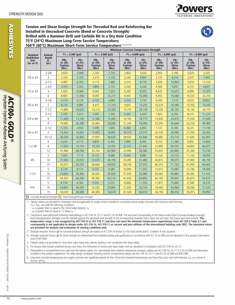
Tension and Shear Design Strength for Threaded Rod and Reinforcing Bar Installed in Uncracked Concrete (Bond or Concrete Strength)Drilled with a Hammer-Drill and Carbide Bit in a Dry Hole Condition75°F (24°C) Maximum Long-Term Service Temperature; 104°F (40°C) Maximum Short-Term Service Temperature1,2,3,4,5,6,7,8
Nominal Rod/Rebar
Size(in. or #)
Embed.Depth
hef
(in.)
Minimum Concrete Compressive Strength
f'c = 2,500 (psi) f'c = 3,000 (psi) f'c = 4,000 (psi) f'c = 6,000 (psi) f'c = 8,000 (psi)
φNcb
or φNa
Tension(lbs.)
φVcb
or φVcp
Shear(lbs.)
φNcb
or φNa
Tension(lbs.)
φVcb
or φVcp
Shear(lbs.)
φNcb
or φNa
Tension(lbs.)
φVcb
or φVcp
Shear(lbs.)
φNcb
or φNa
Tension(lbs.)
φVcb
or φVcp
Shear(lbs.)
φNcb
or φNa
Tension(lbs.)
φVcb
or φVcp
Shear(lbs.)
3/8 or #3
2-3/8 2,635 2,490 2,700 2,755 2,805 3,020 2,955 3,180 3,070 3,305
3 3,330 3,705 3,410 4,100 3,540 4,805 3,735 6,010 3,875 7,045
4-1/2 4,995 6,765 5,115 7,480 5,310 8,770 5,600 10,965 5,810 12,520
1/2 or #4
2-3/4 3,555 3,305 3,895 3,755 4,330 4,520 4,560 5,655 4,735 6,625
4 5,920 6,560 6,065 7,255 6,295 8,505 6,635 10,635 6,890 12,470
6 8,885 11,950 9,095 13,215 9,445 15,490 9,955 19,380 10,335 22,255
5/8 or #5
3-1/8 4,310 4,120 4,720 4,680 5,450 5,720 6,400 7,510 6,625 8,805
5 8,720 9,985 9,475 11,310 9,835 13,255 10,370 16,580 10,765 19,430
7-1/2 13,880 18,625 14,210 20,595 14,755 24,140 15,550 30,195 16,145 34,775
3/4 or #6
3-1/2 5,105 5,015 5,595 5,700 6,460 6,970 7,805 9,255 8,315 11,275
6 11,465 13,595 12,560 15,445 14,165 18,715 14,930 23,410 15,500 27,440
9 19,985 26,300 20,465 29,085 21,245 34,090 22,395 42,640 23,250 49,980
7/8 or #7
3-1/2 5,105 4,930 5,595 5,605 6,460 6,855 7,725 9,100 8,225 11,130
7 14,445 16,605 15,825 18,865 18,275 23,075 20,320 29,490 21,095 34,565
10-1/2 26,540 32,800 27,855 36,635 28,920 42,940 30,485 53,710 31,645 62,955
1 or #8
4 6,240 6,115 6,835 6,945 7,895 8,495 9,255 11,280 9,850 13,800
8 17,650 19,750 19,335 22,435 22,325 27,440 23,890 34,530 24,800 40,475
12 31,980 38,790 32,745 42,900 33,995 50,280 35,835 62,895 37,200 73,720
#9
5 7,445 7,110 8,155 8,080 9,420 9,880 10,535 13,125 11,220 16,055
10 21,060 23,055 23,070 26,190 25,495 31,480 26,875 39,375 27,900 46,150
15 35,975 44,235 36,840 48,920 38,240 57,335 40,310 71,720 41,850 84,065
1-1/4
5 8,720 8,170 9,555 9,285 10,990 11,355 12,015 15,085 12,740 18,300
10 24,665 26,380 26,920 29,930 27,950 35,080 29,460 43,880 30,585 51,435
15 39,435 49,290 40,385 54,510 41,920 63,895 44,190 79,920 45,875 93,675
#10
5 8,720 8,160 9,555 9,270 10,865 11,335 11,875 15,060 12,585 18,270
10 24,665 26,430 26,920 29,985 27,950 35,145 29,460 43,960 30,585 51,525
15 39,435 49,385 40,385 54,610 41,920 64,010 44,190 80,070 45,875 93,850
■ - Concrete Breakout Strength ■ - Bond Strength/Pryout Strength
1. Tabular values are provided for illustration and are applicable for single anchors installed in uncracked normal-weight concrete with minimum slab thickness, ha = hmin, and with the following conditions: - ca1 is greater than or equal to the critical edge distance, cac
- ca2 is greater than or equal to 1.5 times ca1.2. Calculations were performed following methodology in ACI 318-14, Ch.17 and ICC-ES AC308. The load level corresponding to the failure mode listed [Concrete breakout strength,
bond strength/pryout strength] must be checked against the tabulated steel strength of the corresponding threaded rod or rebar size and type, the lowest load level controls. This temperature range is not recognized by ACI 318-14 or ACI 318-11 and does not meet the minimum temperature requirements from ACI 355.4 Table 8.1 and consequently is not applicable to design under ACI 318-14, ACI 318-11 or current and past editions of the international building code (IBC). The tabulated values are provided for analysis and evaluation of existing conditions only.
3. Strength reduction factors (φ) for concrete breakout strength are based on ACI 318-14 Section 5.3 for load combinations. Condition B was assumed. 4. Strength reduction factors (φ) for bond strength are determined from reliability testing and qualification in accordance with ICC-ES AC308 and are tabulated in this product information
and in ESR-2582.5. Tabular values are permitted for short-term static loads only, seismic loading is not considered with these tables. 6. For designs that include combined tension and shear, the interaction of tension and shear loads must be calculated in accordance with ACI 318-14, Ch.17.7. Interpolation is not permitted to be used with the tabular values. For intermediate base material compressive strengths, please see ACI 318-14, Ch.17, ICC-ES AC308 and information
included in this product supplement. For other design conditions including seismic considerations please see ACI 318-14, Ch.17 and ICC-ES AC308 and ESR-2582. 8. Long term concrete temperatures are roughly constant over significant periods of time. Short-term elevated temperatures are those that occur over brief intervals, e.g. as a result of
diurnal cycling.

www.powers.com 16
AD
HESIV
ES
STRENGTH DESIGN (SD)
TECH
MAN
UAL
– AD
HESI
VES
©20
16 P
OW
ERS
VO
LUM
E 1
– R
EV. M
Tension and Shear Design Strength for Threaded Rod and Reinforcing Bar Installed in Uncracked Concrete (Bond or Concrete Strength)Drilled with a Hammer-Drill and Carbide Bit in a Dry Hole Condition122°F (50°C) Maximum Long-Term Service Temperature; 176°F (80°C) Maximum Short-Term Service Temperature1,2,3,4,5,6,7,8,9
®
Nominal Rod/Rebar
Size(in. or #)
Embed.Depth
hef
(in.)
Minimum Concrete Compressive Strength
f'c = 2,500 (psi) f'c = 3,000 (psi) f'c = 4,000 (psi) f'c = 6,000 (psi) f'c = 8,000 (psi)
φNcb
or φNa
Tension(lbs.)
φVcb
or φVcp
Shear(lbs.)
φNcb
or φNa
Tension(lbs.)
φVcb
or φVcp
Shear(lbs.)
φNcb
or φNa
Tension(lbs.)
φVcb
or φVcp
Shear(lbs.)
φNcb
or φNa
Tension(lbs.)
φVcb
or φVcp
Shear(lbs.)
φNcb
or φNa
Tension(lbs.)
φVcb
or φVcp
Shear(lbs.)
3/8 or #3
2-3/8 1,495 1,610 1,535 1,650 1,590 1,715 1,675 1,805 1,740 1,875
3 1,890 2,955 1,935 3,270 2,010 3,830 2,120 4,565 2,200 4,735
4-1/2 2,835 5,395 2,905 5,965 3,015 6,495 3,180 6,845 3,300 7,105
1/2 or #4
2-3/4 2,310 2,780 2,365 3,075 2,455 3,605 2,590 4,505 2,690 5,280
4 3,360 5,230 3,440 5,785 3,575 6,780 3,765 8,110 3,910 8,420
6 5,040 9,530 5,165 10,540 5,360 11,545 5,650 12,170 5,865 12,630
5/8 or #5
3-1/8 3,280 3,695 3,360 4,085 3,490 4,785 3,680 5,990 3,820 7,020
5 5,250 8,155 5,380 9,015 5,585 10,565 5,885 12,675 6,110 13,160
7-1/2 7,880 14,850 8,065 16,420 8,375 18,035 8,825 19,015 9,165 19,735
3/4 or #6
3-1/2 4,285 4,730 4,380 5,230 4,535 6,130 4,760 7,670 4,925 8,990
6 7,565 11,515 7,745 12,730 8,040 14,925 8,475 18,250 8,795 18,950
9 11,345 20,970 11,615 23,190 12,060 25,975 12,710 27,380 13,195 28,420
7/8 or #7
3-1/2 4,370 4,930 4,475 5,470 4,635 6,410 4,865 8,020 5,040 9,400
7 10,295 14,500 10,540 16,035 10,940 18,795 11,535 23,510 11,975 25,790
10-1/2 15,440 26,410 15,810 29,210 16,415 34,235 17,300 37,265 17,960 38,685
1 or #8
4 5,210 6,045 5,325 6,685 5,515 7,835 5,795 9,800 6,000 11,490
8 12,140 17,000 12,430 18,800 12,905 22,040 13,600 27,565 14,120 30,410
12 18,205 30,965 18,645 34,245 19,355 40,140 20,400 43,940 21,180 45,615
#9
5 5,795 6,845 5,925 7,570 6,135 8,875 6,445 11,100 6,670 13,010
10 13,545 19,320 13,865 21,365 14,395 25,045 15,175 31,325 15,755 33,930
15 20,315 35,195 20,800 38,920 21,595 45,620 22,760 49,025 23,630 50,895
1-1/4
5 6,575 7,695 6,720 8,510 6,955 9,975 7,305 12,480 7,565 14,625
10 15,010 21,630 15,370 23,920 15,955 28,035 16,820 35,065 17,460 37,605
15 22,515 39,390 23,055 43,560 23,930 51,060 25,225 54,335 26,190 56,405
#10
5 6,490 7,685 6,635 8,495 6,870 9,960 7,215 12,455 7,470 14,600
10 15,010 21,665 15,370 23,960 15,955 28,085 16,820 35,130 17,460 37,605
15 22,515 39,465 23,055 43,640 23,930 51,155 25,225 54,335 26,190 56,405
■ - Concrete Breakout Strength ■ - Bond Strength/Pryout Strength
1. Tabular values are provided for illustration and are applicable for single anchors installed in uncracked normal-weight concrete with minimum slab thickness, ha = hmin, and with the following conditions: - ca1 is greater than or equal to the critical edge distance, cac
- ca2 is greater than or equal to 1.5 times ca1.2. Calculations were performed according to ACI 318-14, Ch.17 and ICC-ES AC308. The load level corresponding to the failure mode listed [Concrete breakout strength, bond strength/
pryout strength] must be checked against the tabulated steel strength of the corresponding threaded rod or rebar size and type, the lowest load level controls.3. Strength reduction factors (φ) for concrete breakout strength are based on ACI 318-14 Section 5.3 for load combinations. Condition B was assumed. 4. Strength reduction factors (φ) for bond strength are determined from reliability testing and qualification in accordance with ICC-ES AC308 and are tabulated in this product information
and in ESR-2582.5. Tabular values are permitted for static loads only, seismic loading is not considered with these tables. Periodic special inspection must be performed where required by code, see ESR-2582
for applicable information.6. For anchors subjected to tension resulting from sustained loading a supplemental check must be performed according to ACI 318-14 17.3.1.2.7. For designs that include combined tension and shear, the interaction of tension and shear loads must be calculated in accordance with ACI 318-14, Ch.17.8. Interpolation is not permitted to be used with the tabular values. For intermediate base material compressive strengths, please see ACI 318-14, Ch.17, ICC-ES AC308 and information
included in this product supplement. For other design conditions including seismic considerations please see ACI 318-14, Ch.17 and ICC-ES AC308 and ESR-2582.9. Long term concrete temperatures are roughly constant over significant periods of time. Short-term elevated temperatures are those that occur over brief intervals, e.g. as a result of
diurnal cycling.

AD
HESIV
ES
www.powers.com 17
TECH MAN
UAL – ADHESIVES ©2016 PO
WERS VO
LUME 1 – REV. M
STRENGTH DESIGN (SD)
Tension and Shear Design Strength for Threaded Rod and Reinforcing Bar Installed in Uncracked Concrete (Bond or Concrete Strength)Drilled with a Hammer-Drill and Carbide Bit in a Dry Hole Condition162°F (72°C) Maximum Long-Term Service Temperature; 248°F (120°C) Maximum Short-Term Service Temperature1,2,3,4,5,6,7,8,9
®
Nominal Rod/Rebar
Size(in. or #)
Embed.Depth
hef
(in.)
Minimum Concrete Compressive Strength
f'c = 2,500 (psi) f'c = 3,000 (psi) f'c = 4,000 (psi) f'c = 6,000 (psi) f'c = 8,000 (psi)
φNcb
or φNa
Tension(lbs.)
φVcb
or φVcp
Shear(lbs.)
φNcb
or φNa
Tension(lbs.)
φVcb
or φVcp
Shear(lbs.)
φNcb
or φNa
Tension(lbs.)
φVcb
or φVcp
Shear(lbs.)
φNcb
or φNa
Tension(lbs.)
φVcb
or φVcp
Shear(lbs.)
φNcb
or φNa
Tension(lbs.)
φVcb
or φVcp
Shear(lbs.)
3/8 or #3
2-3/8 735 795 755 810 785 845 825 890 855 925
3 930 2,005 955 2,050 990 2,130 1,045 2,245 1,080 2,330
4-1/2 1,395 3,005 1,430 3,080 1,485 3,195 1,565 3,370 1,625 3,495
1/2 or #4
2-3/4 1,135 2,095 1,165 2,315 1,210 2,605 1,275 2,745 1,325 2,850
4 1,655 3,565 1,695 3,650 1,760 3,785 1,855 3,990 1,925 4,145
6 2,480 5,345 2,540 5,470 2,635 5,680 2,780 5,990 2,885 6,215
5/8 or #5
3-1/8 1,615 2,780 1,655 3,075 1,715 3,605 1,810 3,900 1,880 4,045
5 2,585 5,565 2,645 5,700 2,745 5,915 2,895 6,235 3,005 6,475
7-1/2 3,875 8,350 3,970 8,550 4,120 8,875 4,345 9,355 4,510 9,715
3/4 or #6
3-1/2 2,170 3,560 2,225 3,940 2,310 4,615 2,435 5,240 2,525 5,440
6 3,720 8,015 3,810 8,210 3,955 8,520 4,170 8,980 4,330 9,325
9 5,580 12,025 5,715 12,310 5,935 12,780 6,255 13,475 6,495 13,985
7/8 or #7
3-1/2 2,265 3,725 2,315 4,120 2,400 4,830 2,520 5,425 2,610 5,620
7 5,065 10,910 5,185 11,170 5,385 11,600 5,675 12,225 5,890 12,690
10-1/2 7,600 16,365 7,780 16,760 8,075 17,395 8,515 18,340 8,840 19,035
1 or #8
4 2,700 4,555 2,760 5,035 2,860 5,905 3,005 6,465 3,110 6,695
8 5,980 12,810 6,120 13,185 6,355 13,690 6,700 14,430 6,955 14,980
12 8,970 19,315 9,185 19,780 9,535 20,535 10,050 21,645 10,435 22,470
#9
4 3,060 5,200 3,130 5,750 3,240 6,740 3,400 7,325 3,520 7,580
8 6,800 14,650 6,965 15,000 7,230 15,575 7,620 16,415 7,915 17,045
12 10,205 21,975 10,450 22,505 10,845 23,360 11,435 24,625 11,870 25,565
■ - Concrete Breakout Strength ■ - Bond Strength/Pryout Strength
1. Tabular values are provided for illustration and are applicable for single anchors installed in uncracked normal-weight concrete with minimum slab thickness, ha = hmin, and with the following conditions: - ca1 is greater than or equal to the critical edge distance, cac
- ca2 is greater than or equal to 1.5 times ca1.2. Calculations were performed according to ACI 318-14 Ch.17 and ICC-ES AC308. The load level corresponding to the failure mode listed [Concrete breakout strength, bond strength/pryout
strength] must be checked against the tabulated steel strength of the corresponding threaded rod or rebar size and type, the lowest load level controls.3. Strength reduction factors (φ) for concrete breakout strength are based on ACI 318-14 Section 5.3 for load combinations. Condition B was assumed. 4. Strength reduction factors (φ) for bond strength are determined from reliability testing and qualification in accordance with ICC-ES AC308 and are tabulated in this product information
and in ESR-2582.5. Tabular values are permitted for static loads only, seismic loading is not considered with these tables. Periodic special inspection must be performed where required by code, see ESR-2582
for applicable information.6. For anchors subjected to tension resulting from sustained loading a supplemental check must be performed according to ACI 318-14 17.3.1.2.7. For designs that include combined tension and shear, the interaction of tension and shear loads must be calculated in accordance with ACI 318-14 Ch.17.8. Interpolation is not permitted to be used with the tabular values. For intermediate base material compressive strengths, please see ACI 318-14 Ch.17, ICC-ES AC308 and information
included in this product supplement. For other design conditions including seismic considerations please see ACI 318-14 Ch.17 and ICC-ES AC308 and ESR-2582.9. Long term concrete temperatures are roughly constant over significant periods of time. Short-term elevated temperatures are those that occur over brief intervals, e.g. as a result of
diurnal cycling.

www.powers.com 18
AD
HESIV
ES
STRENGTH DESIGN (SD)
TECH
MAN
UAL
– AD
HESI
VES
©20
16 P
OW
ERS
VO
LUM
E 1
– R
EV. M
Tension and Shear Design Strength for Threaded Rod and Reinforcing Bar Installed in Cracked Concrete (Bond or Concrete Strength)Drilled with a Hammer-Drill and Carbide Bit in a Dry Hole Condition75°F (24°C) Maximum Long-Term Service Temperature; 104°F (40°C) Maximum Short-Term Service Temperature1,2,3,4,5,6,7,8
Nominal Rod/Rebar
Size(in. or #)
Embed.Depth
hef
(in.)
Minimum Concrete Compressive Strength
f'c = 2,500 (psi) f'c = 3,000 (psi) f'c = 4,000 (psi) f'c = 6,000 (psi) f'c = 8,000 (psi)
φNcb
or φNa
Tension(lbs.)
φVcb
or φVcp
Shear(lbs.)
φNcb
or φNa
Tension(lbs.)
φVcb
or φVcp
Shear(lbs.)
φNcb
or φNa
Tension(lbs.)
φVcb
or φVcp
Shear(lbs.)
φNcb
or φNa
Tension(lbs.)
φVcb
or φVcp
Shear(lbs.)
φNcb
or φNa
Tension(lbs.)
φVcb
or φVcp
Shear(lbs.)
1/2 or #4
2-3/4 2,445 2,360 2,505 2,680 2,600 3,230 2,740 4,040 2,845 4,730
4 3,555 4,685 3,645 5,185 3,780 6,075 3,985 7,600 4,140 8,905
6 5,335 8,535 5,465 9,440 5,670 11,065 5,980 12,880 6,205 13,370
5/8 or #5
3-1/8 3,050 2,940 3,345 3,340 3,675 4,085 4,005 5,365 4,145 6,290
5 5,790 7,135 5,925 8,075 6,155 9,465 6,485 11,840 6,735 13,880
7-1/2 8,680 13,300 8,890 14,710 9,230 17,245 9,730 20,955 10,100 21,750
3/4 or #6
3-1/2 3,620 3,580 3,965 4,070 4,450 4,980 4,880 6,610 5,200 8,055
6 8,120 9,710 8,535 11,035 8,860 13,370 9,340 16,725 9,695 19,600
9 12,500 18,785 12,800 20,775 13,290 24,350 14,010 30,175 14,545 31,325
7/8 or #7
3-1/2 3,620 3,525 3,965 4,000 4,430 4,895 4,835 6,500 5,145 7,950
7 10,230 11,860 11,210 13,475 12,060 16,485 12,710 21,065 13,195 24,690
10-1/2 17,015 23,430 17,425 26,170 18,090 30,670 19,070 38,365 19,795 42,635
1 or #8
4 4,420 4,365 4,840 4,960 5,590 6,065 6,510 8,060 6,930 9,855
8 12,500 14,105 13,695 16,025 15,815 19,600 16,805 24,665 17,445 28,910
12 22,495 27,710 23,035 30,640 23,910 35,915 25,205 44,925 26,165 52,655
#9
5 5,275 5,080 5,780 5,770 6,670 7,060 8,170 9,375 8,880 11,465
10 14,920 16,465 16,340 18,710 18,870 22,485 21,270 28,125 22,080 32,965
15 27,405 31,595 29,155 34,940 30,265 40,955 31,900 51,230 33,120 60,045
1-1/4
5 6,175 5,835 6,765 6,630 7,815 8,110 9,570 10,775 11,050 13,070
10 17,470 18,845 19,140 21,380 22,100 25,060 26,255 31,345 27,255 36,740
15 32,095 35,210 35,160 38,935 37,365 45,640 39,385 57,085 40,885 66,910
#10
5 6,175 5,830 6,765 6,620 7,815 8,100 9,570 10,755 11,050 13,050
10 17,470 18,880 19,140 21,415 22,100 25,100 26,255 31,400 27,255 36,800
15 32,095 35,275 35,160 39,010 37,365 45,720 39,385 57,190 40,885 67,035
■ - Concrete Breakout Strength ■ - Bond Strength/Pryout Strength
1. Tabular values are provided for illustration and are applicable for single anchors installed in uncracked normal-weight concrete with minimum slab thickness, ha = hmin, and with the following conditions: - ca1 is greater than or equal to the critical edge distance, cac
- ca2 is greater than or equal to 1.5 times ca1.2. Calculations were performed following methodology in ACI 318-14 Ch.17 and ICC-ES AC308. The load level corresponding to the failure mode listed [Concrete breakout strength,
bond strength/pryout strength] must be checked against the tabulated steel strength of the corresponding threaded rod or rebar size and type, the lowest load level controls. This temperature range is not recognized by ACI 318-14 or ACI 318-11 and does not meet the minimum temperature requirements from ACI 355.4 Table 8.1 and consequently is not applicable to design under ACI 318-14, ACI 318-11 or current and past editions of the international building code (IBC). The tabulated values are provided for analysis and evaluation of existing conditions only.
3. Strength reduction factors (φ) for concrete breakout strength are based on ACI 318-14 Section 5.3 for load combinations. Condition B was assumed. 4. Strength reduction factors (φ) for bond strength are determined from reliability testing and qualification in accordance with ICC-ES AC308 and are tabulated in this product information
and in ESR-2582.5. Tabular values are permitted for short-term static loads only, seismic loading is not considered with these tables. 6. For designs that include combined tension and shear, the interaction of tension and shear loads must be calculated in accordance with ACI 318-14 Ch.17.7. Interpolation is not permitted to be used with the tabular values. For intermediate base material compressive strengths, please see ACI 318-14 Ch.17, ICC-ES AC308 and information
included in this product supplement. For other design conditions including seismic considerations please see ACI 318-14 Ch.17 and ICC-ES AC308 and ESR-2582. 8. Long term concrete temperatures are roughly constant over significant periods of time. Short-term elevated temperatures are those that occur over brief intervals, e.g. as a result of
diurnal cycling.

AD
HESIV
ES
www.powers.com 19
TECH MAN
UAL – ADHESIVES ©2016 PO
WERS VO
LUME 1 – REV. M
STRENGTH DESIGN (SD)
Tension and Shear Design Strength for Threaded Rod Installed in Cracked Concrete (Bond or Concrete Strength)Drilled with a Hammer-Drill and Carbide Bit in a Dry Hole Condition122°F (50°C) Maximum Long-Term ServiceTemperature; 176°F (80°C) Maximum Short-Term Service Temperature1,2,3,4,5,6,7,8,9
®
Nominal Rod/Rebar
Size(in.)
Embed.Depth
hef
(in.)
Minimum Concrete Compressive Strength
f'c = 2,500 (psi) f'c = 3,000 (psi) f'c = 4,000 (psi) f'c = 6,000 (psi) f'c = 8,000 (psi)
φNcb
or φNa
Tension(lbs.)
φVcb
or φVcp
Shear(lbs.)
φNcb
or φNa
Tension(lbs.)
φVcb
or φVcp
Shear(lbs.)
φNcb
or φNa
Tension(lbs.)
φVcb
or φVcp
Shear(lbs.)
φNcb
or φNa
Tension(lbs.)
φVcb
or φVcp
Shear(lbs.)
φNcb
or φNa
Tension(lbs.)
φVcb
or φVcp
Shear(lbs.)
1/2
2-3/4 1,400 1,985 1,430 2,195 1,485 2,575 1,565 3,220 1,625 3,505
4 2,035 3,735 2,085 4,130 2,160 4,655 2,280 4,910 2,365 5,095
6 3,050 6,570 3,125 6,730 3,245 6,985 3,420 7,365 3,550 7,645
5/8
3-1/8 2,070 2,640 2,120 2,915 2,200 3,420 2,320 4,275 2,410 5,015
5 3,310 5,825 3,390 6,440 3,520 7,550 3,710 7,995 3,855 8,300
7-1/2 4,970 10,605 5,085 10,955 5,280 11,375 5,565 11,990 5,780 12,445
3/4
3-1/2 2,705 3,380 2,760 3,735 2,860 4,380 3,000 5,480 3,105 6,420
6 4,770 8,225 4,885 9,095 5,070 10,660 5,345 11,510 5,550 11,950
9 7,155 14,980 7,325 15,780 7,605 16,380 8,015 17,265 8,320 17,925
7/8
3-1/2 2,755 3,525 2,820 3,910 2,920 4,580 3,070 5,730 3,180 6,715
7 6,490 10,360 6,645 11,455 6,900 13,425 7,275 15,665 7,550 16,265
10-1/2 9,735 18,865 9,970 20,865 10,350 22,295 10,910 23,500 11,325 24,395
1
4 3,640 4,320 3,720 4,775 3,855 5,595 4,045 7,000 4,190 8,205
8 8,480 12,145 8,680 13,430 9,015 15,740 9,500 19,690 9,865 21,240
12 12,720 22,120 13,025 24,460 13,520 28,670 14,250 30,695 14,795 31,865
1-1/4
5 5,870 5,495 6,000 6,080 6,210 7,125 6,525 8,915 6,755 10,445
10 13,400 15,450 13,720 17,085 14,245 20,025 15,015 25,050 15,590 29,360
15 20,100 28,135 20,585 31,115 21,370 36,470 22,525 45,620 23,385 50,365
■ - Concrete Breakout Strength ■ - Bond Strength/Pryout Strength
1. Tabular values are provided for illustration and are applicable for single anchors installed in uncracked normal-weight concrete with minimum slab thickness, ha = hmin, and with the following conditions: - ca1 is greater than or equal to the critical edge distance, cac
- ca2 is greater than or equal to 1.5 times ca1.2. Calculations were performed according to ACI 318-14 Ch.17 and ICC-ES AC308. The load level corresponding to the failure mode listed [Concrete breakout strength, bond strength/pryout
strength] must be checked against the tabulated steel strength of the corresponding threaded rod or rebar size and type, the lowest load level controls.3. Strength reduction factors (φ) for concrete breakout strength are based on ACI 318-14 Section 5.3 for load combinations. Condition B was assumed. 4. Strength reduction factors (φ) for bond strength are determined from reliability testing and qualification in accordance with ICC-ES AC308 and are tabulated in this product information
and in ESR-2582.5. Tabular values are permitted for static loads only, seismic loading is not considered with these tables. Periodic special inspection must be performed where required by code, see ESR-2582
for applicable information.6. For anchors subjected to tension resulting from sustained loading a supplemental check must be performed according to ACI 318-14 17.3.1.2.7. For designs that include combined tension and shear, the interaction of tension and shear loads must be calculated in accordance with ACI 318-14 Ch.17.8. Interpolation is not permitted to be used with the tabular values. For intermediate base material compressive strengths, please see ACI 318-14 Ch.17, ICC-ES AC308 and information
included in this product supplement. For other design conditions including seismic considerations please see ACI 318-14 Ch.17 and ICC-ES AC308 and ESR-2582.9. Long term concrete temperatures are roughly constant over significant periods of time. Short-term elevated temperatures are those that occur over brief intervals, e.g. as a result of
diurnal cycling.

www.powers.com 20
AD
HESIV
ES
STRENGTH DESIGN (SD)
TECH
MAN
UAL
– AD
HESI
VES
©20
16 P
OW
ERS
VO
LUM
E 1
– R
EV. M
Tension and Shear Design Strength for Reinforcing Bar Installed in Cracked Concrete (Bond or Concrete Strength)Drilled with a Hammer-Drill and Carbide Bit in a Dry Hole Condition122°F (50°C) Maximum Long-Term Service Temperature; 176°F (80°C) Maximum Short-Term Service Temperature1,2,3,4,5,6,7,8,9
®
Nominal Rod/Rebar
Size(#)
Embed.Depth
hef
(in.)
Minimum Concrete Compressive Strength
f'c = 2,500 (psi) f'c = 3,000 (psi) f'c = 4,000 (psi) f'c = 6,000 (psi) f'c = 8,000 (psi)
φNcb
or φNa
Tension(lbs.)
φVcb
or φVcp
Shear(lbs.)
φNcb
or φNa
Tension(lbs.)
φVcb
or φVcp
Shear(lbs.)
φNcb
or φNa
Tension(lbs.)
φVcb
or φVcp
Shear(lbs.)
φNcb
or φNa
Tension(lbs.)
φVcb
or φVcp
Shear(lbs.)
φNcb
or φNa
Tension(lbs.)
φVcb
or φVcp
Shear(lbs.)
#4
2-3/4 930 1,985 950 2,050 990 2,130 1,040 2,245 1,080 2,330
4 1,350 2,910 1,385 2,980 1,435 3,095 1,515 3,265 1,575 3,385
6 2,030 4,365 2,075 4,470 2,155 4,645 2,270 4,895 2,360 5,080
#5
3-1/8 1,375 2,640 1,410 2,915 1,465 3,150 1,540 3,320 1,600 3,445
5 2,200 4,740 2,255 4,855 2,340 5,040 2,465 5,315 2,560 5,515
7-1/2 3,300 7,115 3,380 7,285 3,510 7,560 3,700 7,970 3,840 8,275
#6
3-1/2 1,795 3,380 1,835 3,735 1,900 4,095 1,995 4,300 2,065 4,450
6 3,170 6,830 3,245 6,990 3,370 7,260 3,550 7,650 3,690 7,945
9 4,755 10,240 4,870 10,490 5,055 10,890 5,330 11,475 5,530 11,915
#7
3-1/2 1,830 3,525 1,875 3,910 1,945 4,185 2,040 4,395 2,110 4,550
7 4,315 9,295 4,420 9,515 4,585 9,880 4,835 10,415 5,020 10,810
10-1/2 6,475 13,940 6,630 14,275 6,880 14,820 7,255 15,620 7,530 16,215
#8
4 2,420 4,320 2,475 4,775 2,560 5,515 2,690 5,795 2,785 6,000
8 5,635 12,140 5,770 12,430 5,990 12,905 6,315 13,600 6,555 14,120
12 8,455 18,210 8,655 18,645 8,985 19,355 9,475 20,405 9,835 21,180
#9
5 3,090 4,890 3,155 5,410 3,270 6,340 3,435 7,395 3,555 7,655
10 7,215 13,800 7,390 15,260 7,670 16,520 8,085 17,415 8,395 18,080
15 10,825 23,315 11,085 23,870 11,505 24,780 12,130 26,125 12,590 27,120
#10
5 3,855 5,490 3,940 6,070 4,080 7,115 4,280 8,900 4,435 9,550
10 8,910 15,475 9,120 17,115 9,470 20,060 9,980 21,500 10,365 22,320
15 13,365 28,190 13,685 29,470 14,205 30,595 14,975 32,250 15,545 33,480
■ - Concrete Breakout Strength ■ - Bond Strength/Pryout Strength
1. Tabular values are provided for illustration and are applicable for single anchors installed in uncracked normal-weight concrete with minimum slab thickness, ha = hmin, and with the following conditions: - ca1 is greater than or equal to the critical edge distance, cac
- ca2 is greater than or equal to 1.5 times ca1.2. Calculations were performed according to ACI 318-14 Ch.17 and ICC-ES AC308. The load level corresponding to the failure mode listed [Concrete breakout strength, bond strength/pryout
strength] must be checked against the tabulated steel strength of the corresponding threaded rod or rebar size and type, the lowest load level controls.3. Strength reduction factors (φ) for concrete breakout strength are based on ACI 318-14 Section 5.3 for load combinations. Condition B was assumed. 4. Strength reduction factors (φ) for bond strength are determined from reliability testing and qualification in accordance with ICC-ES AC308 and are tabulated in this product information
and in ESR-2582.5. Tabular values are permitted for static loads only, seismic loading is not considered with these tables. Periodic special inspection must be performed where required by code, see ESR-2582
for applicable information.6. For anchors subjected to tension resulting from sustained loading a supplemental check must be performed according to ACI 318-14 17.3.1.2.7. For designs that include combined tension and shear, the interaction of tension and shear loads must be calculated in accordance with ACI 318-14 Ch.17.8. Interpolation is not permitted to be used with the tabular values. For intermediate base material compressive strengths, please see ACI 318-14 Ch.17, ICC-ES AC308 and information
included in this product supplement. For other design conditions including seismic considerations please see ACI 318-14 Ch.17 and ICC-ES AC308 and ESR-2582.9. Long term concrete temperatures are roughly constant over significant periods of time. Short-term elevated temperatures are those that occur over brief intervals, e.g. as a result of
diurnal cycling.

AD
HESIV
ES
www.powers.com 21
TECH MAN
UAL – ADHESIVES ©2016 PO
WERS VO
LUME 1 – REV. M
STRENGTH DESIGN (SD)
Tension and Shear Design Strength for Threaded Rod Installed in Cracked Concrete (Bond or Concrete Strength)Drilled with a Hammer-Drill and Carbide Bit in a Dry Hole Condition162°F (72°C) Maximum Long-Term Service Temperature; 248°F (120°C) Maximum Short-Term Service Temperature1,2,3,4,5,6,7,8,9
®
Nominal Rod/Rebar
Size(in.)
Embed.Depth
hef
(in.)
Minimum Concrete Compressive Strength
f'c = 2,500 (psi) f'c = 3,000 (psi) f'c = 4,000 (psi) f'c = 6,000 (psi) f'c = 8,000 (psi)
φNcb
or φNa
Tension(lbs.)
φVcb
or φVcp
Shear(lbs.)
φNcb
or φNa
Tension(lbs.)
φVcb
or φVcp
Shear(lbs.)
φNcb
or φNa
Tension(lbs.)
φVcb
or φVcp
Shear(lbs.)
φNcb
or φNa
Tension(lbs.)
φVcb
or φVcp
Shear(lbs.)
φNcb
or φNa
Tension(lbs.)
φVcb
or φVcp
Shear(lbs.)
1/2
2-3/4 690 1,480 705 1,515 730 1,575 770 1,660 800 1,725
4 1,000 2,155 1,025 2,205 1,065 2,290 1,120 2,415 1,165 2,505
6 1,500 3,235 1,535 3,310 1,595 3,435 1,680 3,620 1,745 3,760
5/8
3-1/8 1,015 1,985 1,040 2,195 1,080 2,330 1,140 2,455 1,185 2,550
5 1,625 3,505 1,665 3,590 1,730 3,725 1,825 3,925 1,895 4,075
7-1/2 2,440 5,255 2,500 5,385 2,595 5,590 2,735 5,890 2,840 6,115
3/4
3-1/2 1,365 2,545 1,400 2,815 1,455 3,130 1,530 3,300 1,590 3,425
6 2,345 5,045 2,400 5,170 2,490 5,365 2,625 5,655 2,725 5,870
9 3,515 7,570 3,600 7,750 3,735 8,045 3,940 8,485 4,090 8,805
7/8
3-1/2 1,425 2,660 1,460 2,945 1,510 3,255 1,585 3,415 1,640 3,535
7 3,190 6,870 3,265 7,035 3,390 7,300 3,575 7,700 3,710 7,990
10-1/2 4,785 10,305 4,900 10,550 5,085 10,955 5,360 11,545 5,565 11,985
1
4 1,885 3,255 1,925 3,595 1,990 4,215 2,090 4,505 2,165 4,665
8 4,165 8,970 4,265 9,190 4,430 9,540 4,670 10,055 4,845 10,435
12 6,250 13,460 6,400 13,780 6,640 14,305 7,000 15,080 7,270 15,655
■ - Concrete Breakout Strength ■ - Bond Strength/Pryout Strength
1. Tabular values are provided for illustration and are applicable for single anchors installed in uncracked normal-weight concrete with minimum slab thickness, ha = hmin, and with the following conditions: - ca1 is greater than or equal to the critical edge distance, cac
- ca2 is greater than or equal to 1.5 times ca1.2. Calculations were performed according to ACI 318-14 Ch.17 and ICC-ES AC308. The load level corresponding to the failure mode listed [Concrete breakout strength, bond strength/pryout
strength] must be checked against the tabulated steel strength of the corresponding threaded rod or rebar size and type, the lowest load level controls.3. Strength reduction factors (φ) for concrete breakout strength are based on ACI 318-14 Section 5.3 for load combinations. Condition B was assumed. 4. Strength reduction factors (φ) for bond strength are determined from reliability testing and qualification in accordance with ICC-ES AC308 and are tabulated in this product information
and in ESR-2582.5. Tabular values are permitted for static loads only, seismic loading is not considered with these tables. Periodic special inspection must be performed where required by code, see ESR-2582
for applicable information.6. For anchors subjected to tension resulting from sustained loading a supplemental check must be performed according to ACI 318-14 17.3.1.2.7. For designs that include combined tension and shear, the interaction of tension and shear loads must be calculated in accordance with ACI 318-14 Ch.17.8. Interpolation is not permitted to be used with the tabular values. For intermediate base material compressive strengths, please see ACI 318-14 Ch.17, ICC-ES AC308 and information
included in this product supplement. For other design conditions including seismic considerations please see ACI 318-14 Ch.17 and ICC-ES AC308 and ESR-2582.9. Long term concrete temperatures are roughly constant over significant periods of time. Short-term elevated temperatures are those that occur over brief intervals, e.g. as a result of
diurnal cycling.

www.powers.com 22
AD
HESIV
ES
STRENGTH DESIGN (SD)
TECH
MAN
UAL
– AD
HESI
VES
©20
16 P
OW
ERS
VO
LUM
E 1
– R
EV. M
Tension and Shear Design Strength for Reinforcing Bar Installed in Cracked Concrete (Bond or Concrete Strength)Drilled with a Hammer-Drill and Carbide Bit in a Dry Hole Condition162°F (72°C) Maximum Long-Term Service Temperature;248°F (120°C) Maximum Short-Term Service Temperature1,2,3,4,5,6,7,8,9
®
Nominal Rod/Rebar
Size(#)
Embed.Depth
hef
(in.)
Minimum Concrete Compressive Strength
f'c = 2,500 (psi) f'c = 3,000 (psi) f'c = 4,000 (psi) f'c = 6,000 (psi) f'c = 8,000 (psi)
φNcb
or φNa
Tension(lbs.)
φVcb
or φVcp
Shear(lbs.)
φNcb
or φNa
Tension(lbs.)
φVcb
or φVcp
Shear(lbs.)
φNcb
or φNa
Tension(lbs.)
φVcb
or φVcp
Shear(lbs.)
φNcb
or φNa
Tension(lbs.)
φVcb
or φVcp
Shear(lbs.)
φNcb
or φNa
Tension(lbs.)
φVcb
or φVcp
Shear(lbs.)
#4
2-3/4 460 985 470 1,010 485 1,050 515 1,105 530 1,145
4 665 1,435 680 1,470 710 1,525 745 1,605 775 1,670
6 1,000 2,150 1,025 2,200 1,060 2,285 1,120 2,410 1,160 2,500
#5
3-1/8 680 1,460 695 1,495 720 1,550 760 1,635 790 1,700
5 1,085 2,335 1,110 2,395 1,155 2,485 1,215 2,620 1,260 2,720
7-1/2 1,625 3,505 1,665 3,590 1,730 3,725 1,825 3,925 1,895 4,075
#6
3-1/2 910 1,965 935 2,010 970 2,085 1,020 2,200 1,060 2,285
6 1,560 3,365 1,600 3,445 1,660 3,575 1,750 3,770 1,815 3,915
9 2,345 5,045 2,400 5,170 2,490 5,365 2,625 5,655 2,725 5,870
#7
3-1/2 950 2,050 975 2,095 1,005 2,170 1,055 2,280 1,095 2,360
7 2,125 4,580 2,175 4,690 2,260 4,870 2,385 5,130 2,475 5,325
10-1/2 3,190 6,870 3,265 7,035 3,390 7,300 3,575 7,700 3,710 7,990
#8
4 1,255 2,705 1,285 2,765 1,330 2,860 1,395 3,005 1,445 3,110
8 2,775 5,980 2,845 6,125 2,950 6,360 3,110 6,705 3,230 6,960
12 4,165 8,970 4,265 9,190 4,430 9,540 4,670 10,055 4,845 10,435
#9
5 1,580 3,405 1,615 3,480 1,675 3,605 1,755 3,785 1,820 3,915
10 3,515 7,570 3,600 7,750 3,735 8,045 3,940 8,485 4,090 8,805
15 5,270 11,355 5,400 11,630 5,605 12,070 5,910 12,725 6,135 13,210
■ - Concrete Breakout Strength ■ - Bond Strength/Pryout Strength
1. Tabular values are provided for illustration and are applicable for single anchors installed in uncracked normal-weight concrete with minimum slab thickness, ha = hmin, and with the following conditions: - ca1 is greater than or equal to the critical edge distance, cac
- ca2 is greater than or equal to 1.5 times ca1.2. Calculations were performed according to ACI 318-14 Ch.17 and ICC-ES AC308. The load level corresponding to the failure mode listed [Concrete breakout strength, bond strength/pryout
strength] must be checked against the tabulated steel strength of the corresponding threaded rod or rebar size and type, the lowest load level controls.3. Strength reduction factors (φ) for concrete breakout strength are based on ACI 318-14 Section 5.3 for load combinations. Condition B was assumed. 4. Strength reduction factors (φ) for bond strength are determined from reliability testing and qualification in accordance with ICC-ES AC308 and are tabulated in this product information
and in ESR-2582.5. Tabular values are permitted for static loads only, seismic loading is not considered with these tables. Periodic special inspection must be performed where required by code, see ESR-2582
for applicable information.6. For anchors subjected to tension resulting from sustained loading a supplemental check must be performed according to ACI 318-14 17.3.1.2.7. For designs that include combined tension and shear, the interaction of tension and shear loads must be calculated in accordance with ACI 318-14 Ch.17.8. Interpolation is not permitted to be used with the tabular values. For intermediate base material compressive strengths, please see ACI 318-14 Ch.17, ICC-ES AC308 and information
included in this product supplement. For other design conditions including seismic considerations please see ACI 318-14 Ch.17 and ICC-ES AC308 and ESR-2582.9. Long term concrete temperatures are roughly constant over significant periods of time. Short-term elevated temperatures are those that occur over brief intervals, e.g. as a result of
diurnal cycling.

AD
HESIV
ES
www.powers.com 23
TECH MAN
UAL – ADHESIVES ©2016 PO
WERS VO
LUME 1 – REV. M
STRENGTH DESIGN (SD)
Tension Design of Steel Elements (Steel Strength)1,2
®
Steel Elements - Threaded Rod and Reinforcing Bar
Nominal Rod/Rebar
Size(in. or No.)
ASTM A36 and ASTM
F1554 Grade 36
ASTM F1554
Grade 55
ASTM A193 Grade B7 and ASTM
F1554 Grade 105
ASTM F593 CW Stainless
(Types 304 and 316)
ASTM A193 Grade B8/B8M, Class 1 Stainless (Types 304 and 316)
ASTM A193 Grade B8/
B8M2, Class 2B Stainless
(Types 304 and 316)
ASTM A615 Grade 75
Rebar
ASTM A615 Grade 60
Rebar
ASTM A706 Grade 60
Rebar
ASTM A615 Grade 40
Rebar
ØNsa
Tension(lbs.)
ØNsa
Tension(lbs.)
ØNsa
Tension(lbs.)
ØNsa
Tension(lbs.)
ØNsa
Tension(lbs.)
ØNsa
Tension(lbs.)
ØNsa
Tension(lbs.)
ØNsa
Tension(lbs.)
ØNsa
Tension(lbs.)
ØNsa
Tension(lbs.)
3/8 or #3 3,370 4,360 7,265 5,040 3,315 5,525 7,150 7,425 6,600 4,950
1/2 or #4 6,175 7,980 13,300 9,225 6,070 10,110 13,000 13,500 12,000 9,000
5/8 or #5 9,835 12,715 21,190 14,690 9,660 16,105 20,150 20,925 18,600 13,950
3/4 or #6 14,550 18,815 31,360 18,480 14,300 23,830 28,600 29,700 26,400 19,800
7/8 or #7 20,085 25,970 43,285 25,510 19,735 32,895 39,000 40,500 36,000 -
1 or #8 26,350 34,070 56,785 33,465 25,895 43,160 51,350 53,325 47,400 -
#9 - - - - - - 65,000 67,500 60,000 -
1-1/4 or #10 42,160 54,510 9,100 53,540 41,430 69,050 82,550 85,725 76,200 -
■ - Steel Strength
1. Steel tensile design strength according to ACI 318-14 Ch.17 Appendix D, φNsa = φ • Ase,N • futa
2. The tabulated steel design strength in tension must be checked against the bond strength/concrete capacity design strength to determine the controlling failure mode, the lowest load level controls.
Shear Design of Steel Elements (Steel Strength)1,2
Steel Elements - Threaded Rod and Reinforcing Bar
Nominal Rod/Rebar
Size(in. or No.)
ASTM A36 and ASTM
F1554 Grade 36
ASTM F1554
Grade 55
ASTM A193 Grade B7 and ASTM
F1554 Grade 105
ASTM F593 CW Stainless
(Types 304 and 316)
ASTM A193 Grade B8/B8M, Class 1 Stainless (Types 304 and 316)
ASTM A193 Grade B8/
B8M2, Class 2B Stainless
(Types 304 and 316)
ASTM A615 Grade 75
Rebar
ASTM A615 Grade 60
Rebar
ASTM A706 Grade 60
Rebar
ASTM A615 Grade 40
Rebar
ØNsa
Tension(lbs.)
ØNsa
Tension(lbs.)
ØNsa
Tension(lbs.)
ØNsa
Tension(lbs.)
ØNsa
Tension(lbs.)
ØNsa
Tension(lbs.)
ØNsa
Tension(lbs.)
ØNsa
Tension(lbs.)
ØNsa
Tension(lbs.)
ØNsa
Tension(lbs.)
3/8 or #3 1,755 2,265 3,775 2,790 1,725 2,870 3,960 3,860 3,430 2,575
1/2 or #4 3,210 4,150 6,915 5,110 3,155 5,255 7,200 7,020 6,240 4,680
5/8 or #5 5,115 6,610 11,020 8,135 5,025 8,375 11,160 10,880 9,670 7,255
3/4 or #6 7,565 9,785 16,305 10,235 7,435 12,390 15,840 15,445 13,730 10,295
7/8 or #7 10,445 13,505 22,505 14,130 10,265 17,105 21,600 21,060 18,720 -
1 or #8 13,700 17,715 29,525 18,535 13,465 22,445 28,440 27,730 24,650 -
#9 - - - - - - 36,000 35,100 31,200 -
1-1/4 or #10 21,920 28,345 4,735 29,655 21,545 35,905 45,720 44,575 39,625 -
■ - Steel Strength
1. Steel shear design strength according to ACI 318-14 Ch.17 Appendix D, φVsa = φ • 0.60 • Ase,V • futa
2. The tabulated steel design strength in shear must be checked against the bond strength/concrete capacity design strength to determine the controlling failure mode, the lowest load level controls.

www.powers.com 24
AD
HESIV
ES
INSTALLATION INSTRUCTIONS (SOLID BASE MATERIALS)
TECH
MAN
UAL
– AD
HESI
VES
©20
16 P
OW
ERS
VO
LUM
E 1
– R
EV. M
INSTALLATION INSTRUCTIONS (SOLID BASE MATERIALS)DRILLING
1- Drill a hole into the base material with a rotary hammer drill tool to the size and embedment required by the selected steel anchor element (see installation specifications for threaded rod and reinforcing bar). The tolerances of the carbide drill bit must meet ANSI Standard B212.15.
• Precaution: Use suitable eye and skin protection. Avoid inhalation of dust during drilling and/or removal.
• Note! In case of standing water in the drilled hole (flooded hole condition), all the water has to be removed from the hole (e.g. vacuum, compressed air, etc.) prior to cleaning.
HOLE CLEANING DRY (BLOW 4X, BRUSH 4X, BLOW 4X)
4X
2a- Starting from the bottom or back of the anchor hole, blow the hole clean using a compressed air nozzle (min. 90 psi) or a hand pump (supplied by Powers Fasteners) a minimum of four times (4x).
• Use a compressed air nozzle (min. 90 psi) or a hand pump (min. volume 25 fl. oz.) for anchor rod 3/8" to 3/4" diameter or reinforcing bar (rebar) sizes #3 to #6.
• Use a compressed air nozzle (min. 90 psi) for anchor rod 7/8" to 1-1/4" diameter and rebar sizes #7 to #10. A hand pump shall not be used with these anchor sizes.
4X
2b- Determine wire brush diameter (see installation specifications) and attach the brush with adaptor to a rotary drill tool or battery screwgun. Brush the hole with the selected wire brush a minimum of four times (4x). A brush extension (supplied by Powers Fasteners, Cat. #08282) should be used for holes drilled deeper than the listed brush length.
• The wire brush diameter should be checked periodically during use. The brush must be replaced if it becomes worn and does not come into contact with the sides of the drilled hole.
4X
2c- Finally, blow the hole clean again a minimum of four times (4x).• Use a compressed air nozzle (min. 90 psi) or a hand pump (min. volume 25 fl. oz.) for anchor rod 3/8" to 3/4" diameter or reinforcing bar
(rebar) sizes #3 to #6.• Use a compressed air nozzle (min. 90 psi) for anchor rod 7/8" to 1-1/4" diameter and rebar sizes #7 to #10. A hand pump shall not be used
with these anchor sizes.• When finished the hole should be clean and free of dust, debris, ice, grease, oil or other foreign material.
PREPARING3- Check adhesive expiration date on cartridge label. Do not use expired product. Review Safety Data Sheet (SDS) before use. Cartridge
temperature must be between 23°F - 95°F (-5°C - 35°C) when in use unless otherwise noted. Review gel (working) and cure time table. Consideration should be given to the reduced gel time of the adhesive in warm temperatures.
• Attach a supplied mixing nozzle to the cartridge. Do not modify the mixer in any way and make sure the mixing element is inside the nozzle. Load the cartridge into the correct dispensing tool.
• Note: Always use a new mixing nozzle with new cartridges of adhesive and also for all work interruptions exceeding the published working time of the adhesive.
hef
4- Prior to inserting the anchor rod or rebar into the filled bore hole, the position of the embedment depth has to be marked on the anchor• Verify anchor element is straight and free of surface damage.
3X
5- Adhesive must be properly mixed to achieve published properties. Prior to dispensing adhesive into the drilled hole, separately dispense at least three full strokes of adhesive through the mixing nozzle until the adhesive is a consistent GRAY color. Do not attach a used nozzle when changing to a new cartridge.
• Review and note the published working and cure times (see gel time and curing time table) prior to injection of the mixed adhesive into the cleaned anchor hole.
INSTALLATION6- Fill the cleaned hole half to two-thirds full with mixed adhesive starting from the bottom or back of the anchor hole. Slowly
withdraw the mixing nozzle as the hole fills to avoid creating air pockets or voids. For embedment depth greater than 7-1/2" an extension nozzle must be used with the mixing nozzle.
• Piston plugs (see installation specifications) must be used with and attached to the mixing nozzle and extension tube for horizontal and overhead installations in concrete except with anchor rod 3/8" and rebar size #3. Insert piston plug to the back of the drilled hole and inject as described in the method above. During installation the piston plug will be naturally extruded from the drilled holeby the adhesive pressure.
• Attention! Do not install anchors overhead without proper training and installation hardware provided by Powers Fasteners. Contact Powers for details prior to use.
WITH PISTON PLUG:
7- The anchor should be free of dirt, grease, oil or other foreign material. Push clean threaded rod or reinforcing bar into the anchor hole while turning slightly to ensure positive distribution of the adhesive until the embedment depth is reached. Observe the gel (working) time.
8- Be sure that the anchor is fully seated at the bottom of the hole and that some adhesive has flowed from the hole and all around the top of the anchor. If there is not enough adhesive in the hole, the installation must be repeated. The anchor shall not be moved after placement and during cure.
CURING AND LOADINGe.g.
68˚F
45min
9- Allow the adhesive anchor to cure to the specified full curing time prior to applying any load (reference gel time and curing time table).
• Do not disturb, torque or load the anchor until it is fully cured.
Tmax
10- After full curing of the adhesive anchor, a fixture can be installed to the anchor and tightened up to the maximum torque (reference gel time and curing table) by using a calibrated torque wrench.
• Take care not to exceed the maximum torque for the selected anchor.

AD
HESIV
ES
www.powers.com 25
TECH MAN
UAL – ADHESIVES ©2016 PO
WERS VO
LUME 1 – REV. M
INSTALLATION INSTRUCTIONS (HOLLOW BASE MATERIALS)
INSTALLATION INSTRUCTIONS (HOLLOW BASE MATERIALS)
DRILLING
1- Drill a hole into the base material with a rotary drill tool to the size and embedment for the required by the selected screen tube size and steel anchor element (see installation specifications for threaded rod in hollow base material with screen tube supplied by Powers Fasteners). The tolerances of the drill bit used should meet the requirements of ANSI B212.15.
• Precaution: Wear suitable eye and skin protection. Avoid inhalation of dust during drilling and/or removal.
HOLE CLEANING ( BLOW 2X, BRUSH 2X, BLOW 2X)
2X
2- Starting from the bottom or back of the anchor hole, blow the hole clean with a hand pump (min. volume 25 fl.oz. supplied by Powers Fasteners) or compressed air nozzle a minimum of two times (2x).
2X
• Determine the wire brush diameter (see installation specifications) and attach the brush with adaptor to a rotary drill tool or battery screw gun. Brush the hole with the selected wire brush a minimum of two times (2x). A brush extension (supplied by Powers Fasteners, Cat #08282) should be used for holes drilled deeper than the listed brush length.
• The wire brush should be checked periodically during use. The brush must be replaced if it becomes worn and does not come in contact with sides of the drill hole.
2X
• Finally, blow the hole clean again a minimum of two times (2x)
• When finished the hole should be clean and free of dust, debris, ice, grease, oil or other foreign material.
PREPARING3- Check adhesive expiration date on cartridge label. Do not use expired product. Review Safety Data Sheet (SDS) before use. Cartridge
temperature must be between 23°F - 95°F (-5°C - 35°C) when in use unless otherwise noted. Review gel (working) time and curingtime table. Consideration should be given to the reduced gel (working) time of the adhesive in warm temperatures.
• Attach a supplied mixing nozzle to the cartridge. Do not modify the mixer in any way and make sure the mixing element is inside the nozzle. Load the cartridge into the correct dispensing tool.
• Note: Always use a new mixing nozzle with new cartridges of adhesive and also for all work interruptions exceeding the published working time of the adhesive.
hef
4- Prior to inserting the anchor into the filled screen tube, the position of the embedment depth has to be marked on the anchor.Verify anchor element is straight and free of surface damage.
3X
5- Adhesive must be properly mixed to achieve published properties. Prior to dispensing adhesive into the drilled hole, separately dispense at least three full strokes of adhesive through the mixing nozzle until the adhesive is a consistent GRAY color. Do not attach a used nozzle when changing to a new cartridge.
• Review and note the published working and cure times (see gel time and curing time table) prior to injection of the mixed adhesive into the screen tube.
INSTALLATION
6- Select a screen tube of suitable length (supplied by Powers Fasteners). Fill the screen tube full with adhesive starting from the bottom or back of the tube. Slowly withdraw the mixing nozzle as the screen fills to avoid creating air pockets or voids. A plastic extension tube supplied by Powers Fasteners must be used with the mixing nozzle if the back of the screen tube cannot be reached.
7- Insert the screen tube filled with adhesive into the cleaned anchor hole.
8- Prior to inserting the anchor rod into the screen tube inspect it to ensure that it is free of dirt, grease, oil or other foreign material.
• Push the threaded rod into the screen tube while turning slightly to ensure positive distribution of the adhesive until back of the tube is reached.
CURING AND FIXTURE
e.g.
68˚F
45mins
9- Allow the adhesive anchor to cure to the specified full curing time prior to applying any load.
• Do not disturb, torque or load the anchor until it is fully cured (see gel time and curing time table).
Tmax10- After full curing of the adhesive anchor, a fixture can be installed to the anchor and tightened up to the maximum torque (see installation
specifications for threaded rod in hollow base material) by using a calibrated torque wrench.
• Take care not to exceed the maximum torque for the selected anchor.

www.powers.com 26
AD
HESIV
ES
REFERENCE TABLES FOR INSTALLATION
TECH
MAN
UAL
– AD
HESI
VES
©20
16 P
OW
ERS
VO
LUM
E 1
– R
EV. M
REFERENCE TABLES FOR INSTALLATIONGel (working) Time and Curing Table
Temperature of Base MaterialGel (working) Time Full Curing Time
˚F ˚C
14 -10 90 minutes 24 hours
23 -5 90 minutes 14 hours
32 0 45 minutes 7 hours
41 5 25 minutes 2 hours
50 10 15 minutes 90 minutes
68 20 6 minutes 45 minutes
86 30 4 minutes 25 minutes
95 35 2 minutes 20 minutes
104 40 1.5 minutes 15 minutes
The gel (working) times listed for 32o
F to 95o
F are also applicable for the temperature of the adhesive and use of mixing nozzes during installation.For installations in base material temperatures between 14
o
F and 23o
F (-10ºC and -5ºC) the cartridge temperature must be conditioned to between 68o
F and 95o
F (20o
C - 35o
C).
Hole Cleaning Equipment Selection Table for AC100+ GoldThreaded Rod
Diameter(inch)
Rebar Size(no.)
ANSI Drill BitDiameter
(inch)
Min. BrushDiameter, Dmin
(inches)
Brush Length, L(inches)
Steel WireBrush
(Cat. #)
Blowout Tool
Number of Cleaning Actions
Solid Base Material
3/8 #3 7/16 0.475 6-3/4 08284
Hand-pump(Cat#08280)
orcompressed air
nozzle 4x blowing4x brushing4x blowing
1/2 - 9/16 0.600 6-3/4 08285
- #4 5/8 0.670 6-3/4 08275
5/8 #5 11/16 0.735 7-7/8 08286
5/8 #5 3/4 0.780 7-7/8 08278
3/4 #6 7/8 0.920 7-7/8 08287
7/8 #7 1 1.045 11-7/8 08288
Compressed airnozzle only
1 #8 1-1/8 1.175 11-7/8 08289
1-1/4 #9 1-3/8 1.425 11-7/8 08290
- #10 1-1/2 1.550 11-7/8 08291
Hollow Base Material
3/8 - 1/2 0.600 6-3/4 08285
Hand pump (Cat# 08280) or compressed air
nozzle
2x blowing2x brushing2x blowing
3/8 -- 9/16 0.735 7-7/8 08286
1/2 - 5/8 0.735 7-7/8 08286
1/2 -- 3/4 0.780 7-7/8 08278
5/8 - 3/4 0.780 7-7/8 08278
5/8 - 7/8 0.920 7-7/8 08287
An SDS-plus adaptor (Cat. #08283) or Jacobs chuck style adaptor (Cat. #08296) is required to attach a steel wire brush to the drill tool.A brush extension (Cat#08282) must be used for holes drilled deeper than the listed brush length.
Adhesive Piston PlugsThreaded Rod
Diameter(inch)
RebarSize(no.)
ANSI Drill BitDiameter
(inch)
PlugSize
(inch)
PlasticPlug
(Cat. #)
HorizontalInstallations
1/2 #4 9/16 9/16 08302
- #4 5/8 5/8 08304
5/8 #5 11/16 11/16 08258
3/4 3/4 08259
3/4 #6 7/8 7/8 08300
7/8 #7 1 1 08301
1 #8 1-1/8 1-1/8 08303
1-1/4 #9 1-3/8 1-3/8 08305
- #10 1-1/2 1-1/2 08309
A plastic extension tube (3/8" dia.) must be used with piston plugs.
PERMISSIBLE INSTALLATION CONDITIONS (ADHESIVE)Dry Concrete: cured concrete that, at the time of adhesive anchor installation, has not been exposed to water for the preceding 14 days.Water-Saturated Concrete (wet): cured concrete that, at the time of adhesive anchor installation, has been exposed to water over a suffi cient length of time to have the maximum possible amount of absorbed water into the concrete pore structure to a depth equal to the anchor embedment depth.Water-Filled Holes (fl ooded): cured concrete that is water-saturated and where the drilled hole contains standing water at the time of anchor installation.

AD
HESIV
ES
www.powers.com 27
TECH MAN
UAL – ADHESIVES ©2016 PO
WERS VO
LUME 1 – REV. M
ORDERING INFORMATION
ORDERING INFORMATION
AC100+ Gold CartridgesCat No. Description Std. Box Std. Carton Pallet
8478SD AC100+ Gold 10 fl. oz. Quik-Shot 12 - 972
8486SD AC100+ Gold 12 fl. oz. dual cartridge 12 - 864
8490SD AC100+ Gold 28 fl. oz. dual cartridge 8 - 400
One AC100+ Gold mixing nozzle is packaged with each cartridge.AC100+ Gold mixing nozzles must be used to ensure complete and proper mixing of the adhesive.
Cartridge System Mixing Nozzles
Cat No. Description Std. Pack/Box Std. Carton
08293 Extra mixing nozzle for AC100+ Gold (10 oz. & 12 oz.) 2 24
08294 Extra mixing nozzle (with a 8" extension) for AC100+ Gold 28 oz. 2 24
08281 Mixing nozzle extension, 8" minimum 2 24
08297 Mixing nozzle extension, 20" long
Dispensing Tools for Injection Adhesive
Cat No. Description Std. Box Std. Carton
08437 Manual caulking gun for Quik-Shot 1 12
08479 High performance caulking gun for Quik-Shot 1 6
08485 AC100+ Gold 10 oz. & 12 oz. high performance manual tool 1 20
08494 AC100+ Gold 28 oz. standard all metal manual tool 1 -
08496 AC100+ Gold 28 oz. pneumatic tool 1 -
DCE59501 AC100+ Gold 28 oz. 20v battery powered dispensing tool 1 -
Hole Cleaning Tools and Accessories
Cat No. Description Std. Box
08284 Wire brush for 7/16"ANSI hole (3/8" rod or #3 rebar), 6-3/4" length 1
08285 Wire brush for 9/16"ANSI hole (1/2" rod or #4 rebar), 6-3/4" length 1
08286 Wire brush for 11/16"ANSI hole (5/8" rod or #5 rebar), 7-7/8" length 1
08278 Wire brush for 3/4"ANSI hole (5/8" rod or #5 rebar), 7-7/8" length 1
08287 Wire brush for 7/8"ANSI hole (3/4" rod or #6 rebar), 7-7/8" length 1
08288 Wire brush for 1"ANSI hole (7/8" rod or #7 rebar), 11-7/8" length 1
08289 Wire brush for 1-1/8"ANSI hole (1" rod or #8 rebar), 11-7/8" length 1
08290 Wire brush for 1-3/8"ANSI hole (1-1/4" rod or #9 rebar), 11-7/8" length 1
08291 Wire brush for 1-1/2"ANSI hole ( #10 rebar), 11-7/8" length 1
08283 SDS-plus adapter for steel brushes 1
08296 Standard drill adapter for steel brushes (e.g. Jacobs Chuck) 1
08282 Steel brush extension, 12" length 1
08280 Hand pump/dust blower (25 fl. oz. cylinder volume) 1
08292 Air compressor nozzle with extension, 18" length 1
52073Adhesive cleaning kit, includes 4 wire brushes (08284, 08285, 08286, 08287), steel brush extension (08282), SDS-plus adapter (08283), standard drill adapter (08296),
hand pump/dust blower (08280), gloves and safety glasses1

www.powers.com 28
AD
HESIV
ES
ORDERING INFORMATION
TECH
MAN
UAL
– AD
HESI
VES
©20
16 P
OW
ERS
VO
LUM
E 1
– R
EV. M
Adhesive Piston Plugs
Cat. No. Description ANSI Drill Dia.
Reinforcing Bar Size
Threaded Rod Size Std. Bag Std. Ctd.
08302 9/16" Plug 9/16" 1/2" #4 10 100
08304 5/8" Plug 5/8" - #4 10 100
08258 11/16" Plug 11/16"5/8" #5
10 100
08259 3/4" Plug 3/4" 10 100
08300 7/8" Plug 7/8" #6 3/4" 10 100
08301 1" Plug 1" #7 7/8" 10 100
08303 1-1/8" Plug 1-1/8" #8 1" 10 100
08305 1-3/8" Plug 1-3/8" #9 1-1/4" 10 100
08309 1-1/2" Plug 1-1/2" #10 - 10 100
Stainless Steel Screen TubesCat. No. Description Drill Diameter Standard Carton
07960 1/4" x 2" Screen Tube 3/8" 25
07862 1/4" x 6" Screen Tube* 3/8" 25
07864 1/4" x 8"Screen Tube* 3/8" 25
07856 3/8" x 2" Screen Tube 1/2" 25
07961 3/8" x 3-1/2" Screen Tube 1/2" 25
07962 3/8" x 6" Screen Tube* 1/2" 25
07963 3/8" x 8" Screen Tube* 1/2" 25
07964 3/8" x 10" Screen Tube* 1/2" 25
07959 3/8" x 12" Screen Tube* 1/2" 25
07857 1/2" x 2" Screen Tube 5/8" 25
07965 1/2" x 3-1/2" Screen Tube 5/8" 25
07966 1/2" x 6" Screen Tube* 5/8" 25
07967 1/2" x 8" Screen Tube* 5/8" 25
07968 1/2" x 10" Screen Tube* 5/8" 25
07858 5/8" x 2" Screen Tube 3/4" 25
07969 5/8" x 4-1/2" Screen Tube 3/4" 20
07970 5/8" x 6" Screen Tube 3/4" 20
07971 5/8" x 8" Screen Tube* 3/4" 20
07972 5/8" x 10" Screen Tube* 3/4" 20
07859 3/4" x 2" Screen Tube 7/8" 25
07855 15/16" x 2" Screen Tube 1" 25
Screen tubes are made from a 300 series stainless steel. The nominal diameter of the screen listed indicates the matching rod diameter.
*Includes extension tubing.
Plastic Screen TubesCat. No. Description Drill Diameter Standard Carton
08470 1/4" x 1-3/4" Plastic Screen 1/2" 25
08473 3/8" x 2-3/4" Plastic Screen 9/16" 25
08310 3/8" x 3-1/2" Plastic Screen 9/16" 25
08311 3/8" x 6" Plastic Screen 9/16" 25
08313 3/8" x 8" Plastic Screen 9/16" 25
08315 1/2" x 3-1/2" Plastic Screen 3/4" 25
08317 1/2" x 6" Plastic Screen 3/4" 25
08321 5/8" x 6" Plastic Screen 7/8" 25