Embed Size (px)
DESCRIPTION
Air cooled condenser v
Citation preview
GEA Heat Exchangers
Direct Air Cooled Condensing vs. Indirect Air Cooled Condensing Comparison Studies
ACC User Group Presentation
GEA Heat Exchangers
Topics of Discussion
Heller Process Diagram
Major Components of Heller Cooling Systems Case Studies
GEA Heat Exchangers
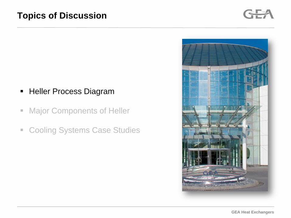
Flow Diagram
3
GEA Heat Exchangers
Topics of Discussion
Heller Process Diagram
Major Components of Heller Cooling Systems Case Studies
GEA Heat Exchangers
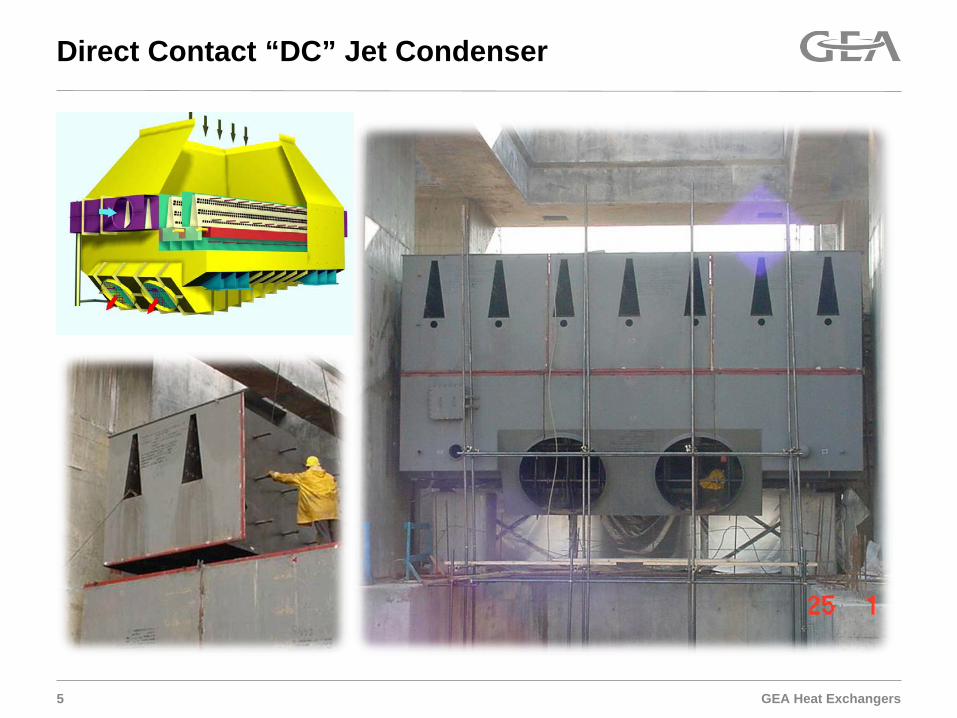
Direct Contact “DC” Jet Condenser
5
GEA Heat Exchangers 6
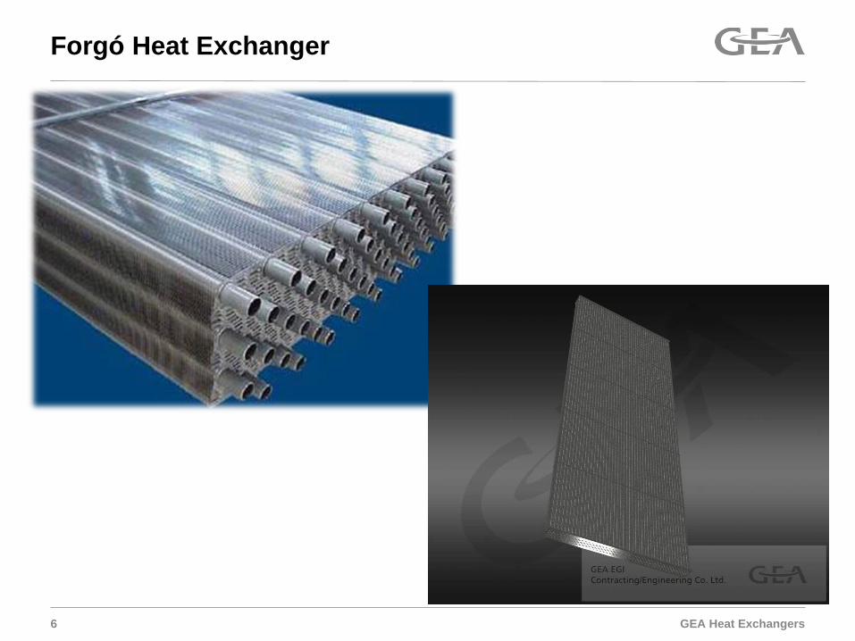
Forgó Heat Exchanger
GEA Heat Exchangers
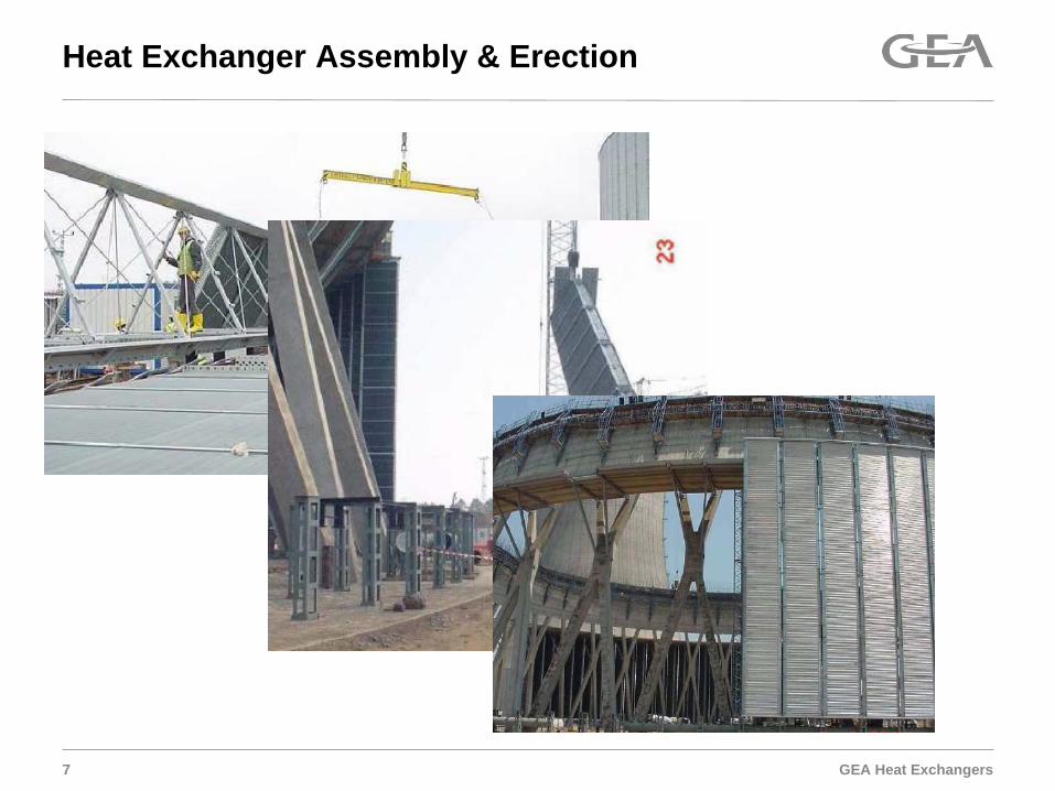
Heat Exchanger Assembly & Erection
7
GEA Heat Exchangers
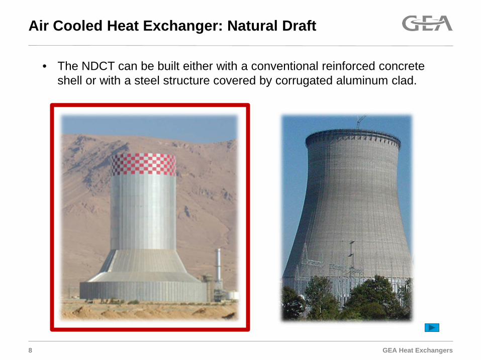
Air Cooled Heat Exchanger: Natural Draft
8
• The NDCT can be built either with a conventional reinforced concrete shell or with a steel structure covered by corrugated aluminum clad.

GEA Heat Exchangers
Air Cooled Heat Exchanger: Mechanical Draft
9
GEA Heat Exchangers
Topics of Discussion
Heller Process Diagram
Major Components of Heller Cooling Systems Case Studies

GEA Heat Exchangers
Illustrative Case Study 1
1. Aux Power Benefit (NDT) 2. Cold Condensing
GEA Heat Exchangers 12 Copyright by GEA EGI
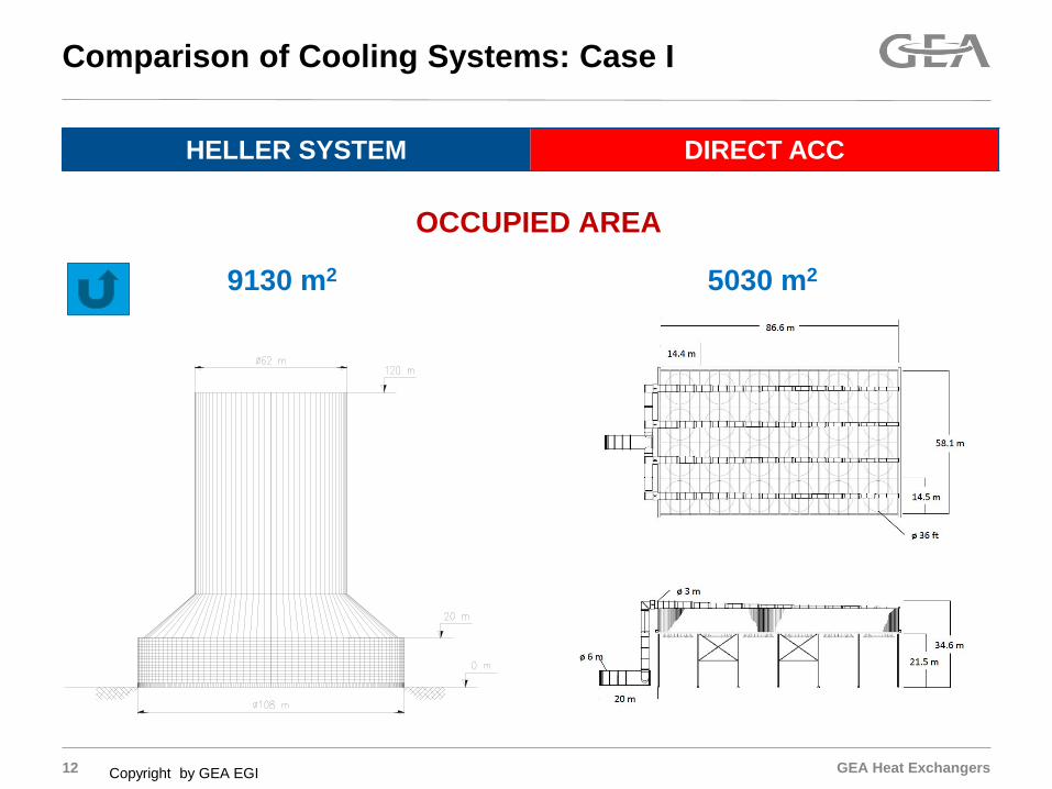
HELLER SYSTEM DIRECT ACC
OCCUPIED AREA
5030 m2 9130 m2
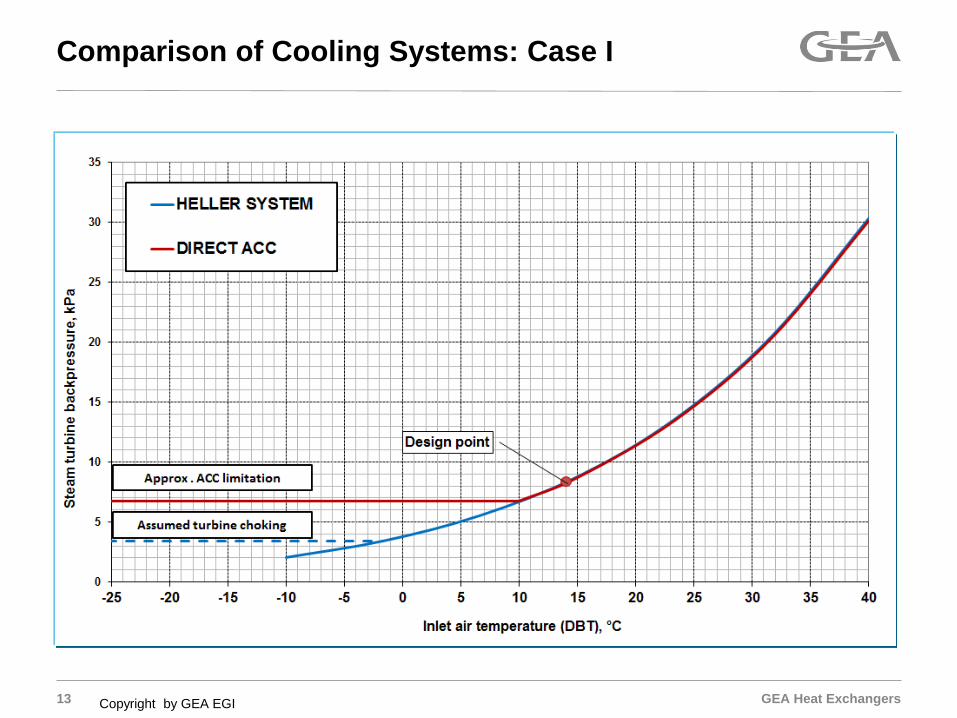
Comparison of Cooling Systems: Case I
GEA Heat Exchangers 13 Copyright by GEA EGI
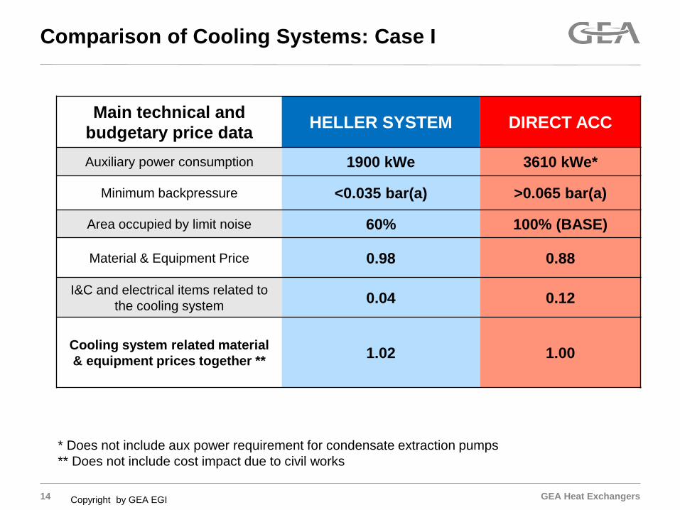
Comparison of Cooling Systems: Case I
GEA Heat Exchangers 14 Copyright by GEA EGI
Main technical and budgetary price data HELLER SYSTEM DIRECT ACC
Auxiliary power consumption 1900 kWe 3610 kWe*
Minimum backpressure <0.035 bar(a) >0.065 bar(a)
Area occupied by limit noise 60% 100% (BASE)
Material & Equipment Price 0.98 0.88
I&C and electrical items related to the cooling system 0.04 0.12
Cooling system related material & equipment prices together **
1.02 1.00
Comparison of Cooling Systems: Case I
* Does not include aux power requirement for condensate extraction pumps ** Does not include cost impact due to civil works
GEA Heat Exchangers
Illustrative Case Study 2
1. Aux Power Benefit (NDT) 2. Efficient Use of Limited Wet Evaporative Cooling
GEA Heat Exchangers
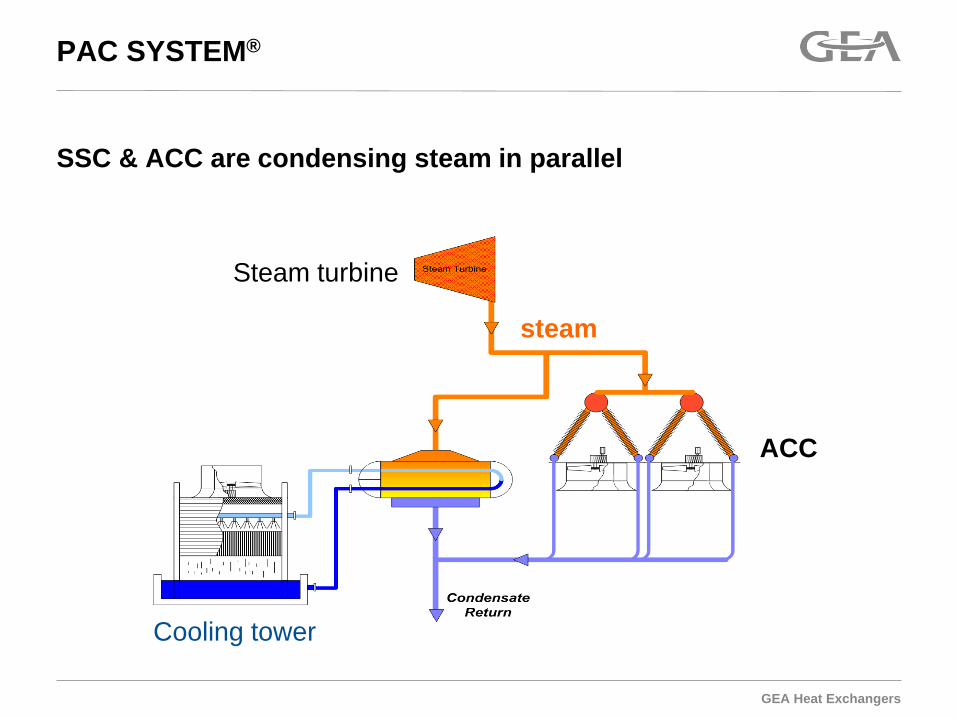
SSC & ACC are condensing steam in parallel
PAC SYSTEM®
Cooling tower
ACC
Steam turbine
steam

GEA Heat Exchangers
Dry/Wet Separate Circuit For Combination System
17
Dry ACHE Tower (Mechanical Draft or Natural Draft)
Hybrid Condenser
Wet Cooling Tower
GEA Heat Exchangers
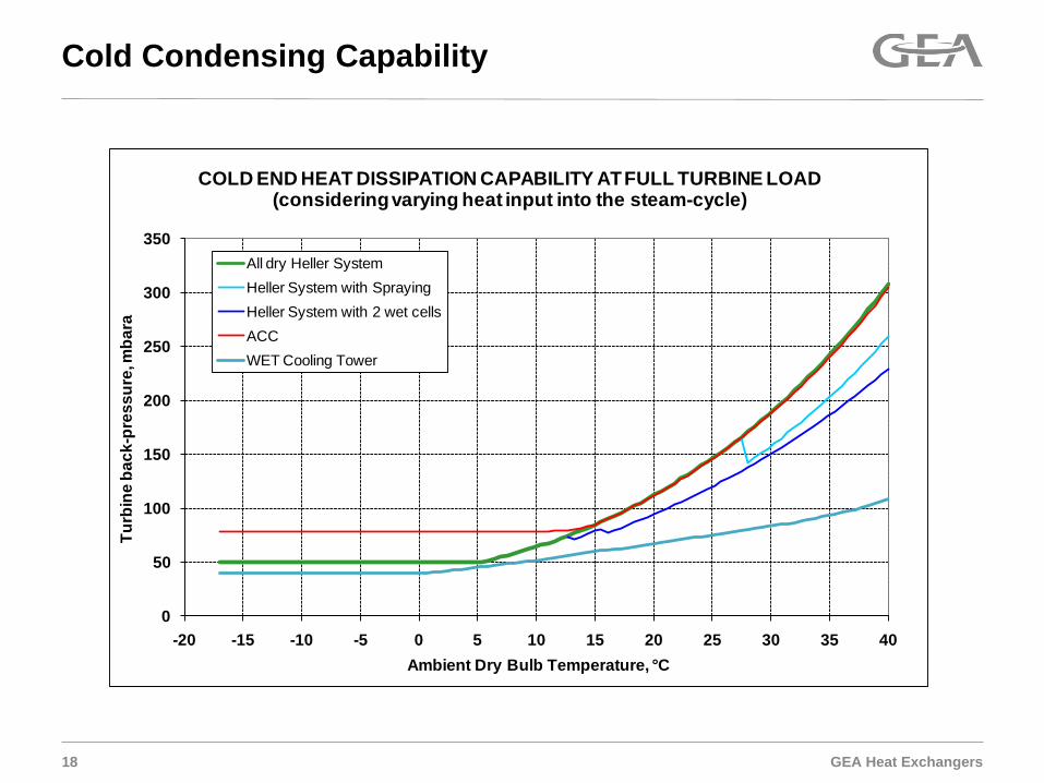
Cold Condensing Capability
18
0
50
100
150
200
250
300
350
-20 -15 -10 -5 0 5 10 15 20 25 30 35 40
Turb
ine
back
-pre
ssur
e, m
bara
Ambient Dry Bulb Temperature, °C
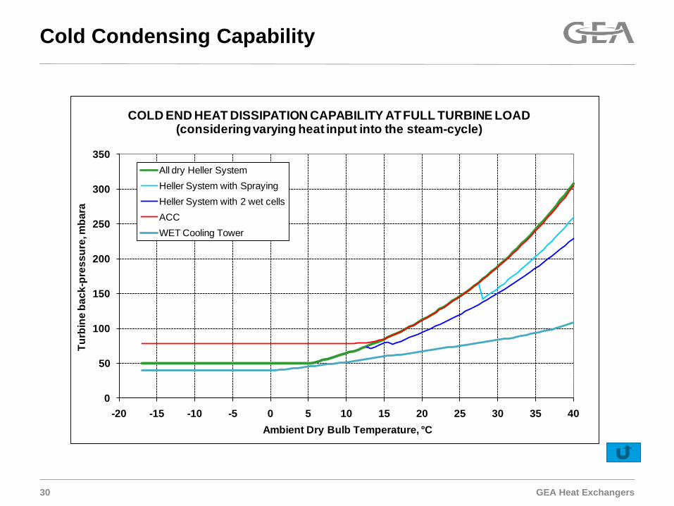
COLD END HEAT DISSIPATION CAPABILITY AT FULL TURBINE LOAD(considering varying heat input into the steam-cycle)
All dry Heller SystemHeller System with SprayingHeller System with 2 wet cellsACCWET Cooling Tower
GEA Heat Exchangers 19 Copyright by GEA EGI
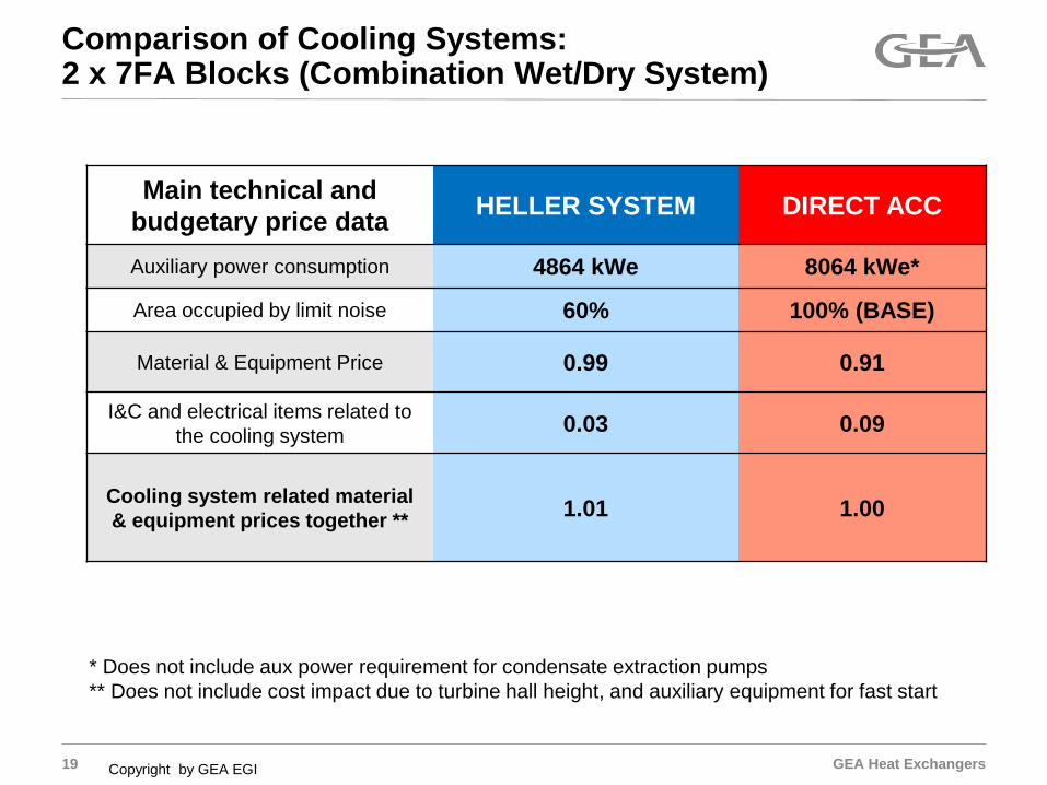
Main technical and budgetary price data HELLER SYSTEM DIRECT ACC
Auxiliary power consumption 4864 kWe 8064 kWe*
Area occupied by limit noise 60% 100% (BASE)
Material & Equipment Price 0.99 0.91
I&C and electrical items related to the cooling system 0.03 0.09
Cooling system related material & equipment prices together **
1.01 1.00
Comparison of Cooling Systems: 2 x 7FA Blocks (Combination Wet/Dry System)
* Does not include aux power requirement for condensate extraction pumps ** Does not include cost impact due to turbine hall height, and auxiliary equipment for fast start
GEA Heat Exchangers
Illustrative Case Study 3
1. Footprint / Layout Flexibility (MDT) 2. Rapid Response
GEA Heat Exchangers 21
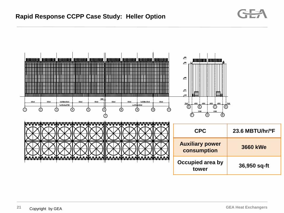
Rapid Response CCPP Case Study: Heller Option
Copyright by GEA
CPC 23.6 MBTU/hr/ºF
Auxiliary power consumption 3660 kWe
Occupied area by tower 36,950 sq-ft
GEA Heat Exchangers 22
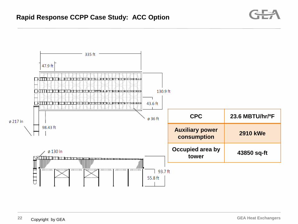
Rapid Response CCPP Case Study: ACC Option
Copyright by GEA
CPC 23.6 MBTU/hr/ºF
Auxiliary power consumption 2910 kWe
Occupied area by tower 43850 sq-ft
GEA Heat Exchangers 23 Copyright by GEA
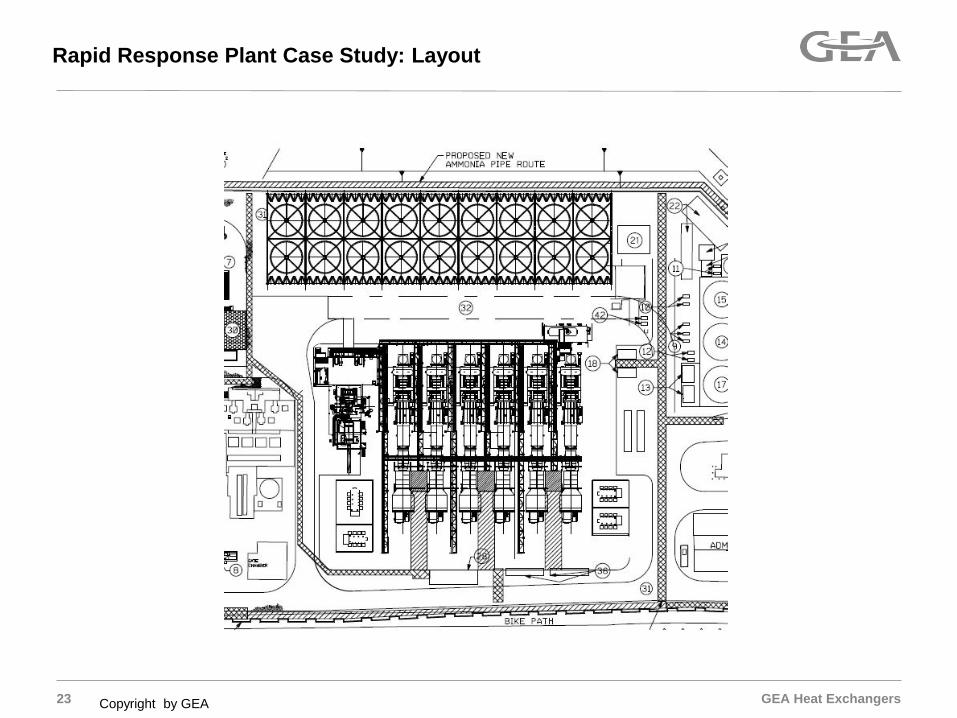
Rapid Response Plant Case Study: Layout

GEA Heat Exchangers 24
Rapid Response Study: Comparison Cooling System Options
Copyright by GEA
Main technical and budgetary price data HELLER SYSTEM DIRECT ACC
Auxiliary power consumption 3660 kWe 2910 kWe
Minimum backpressure <0.035 bar(a) >0.06 bar(a)
Material & Equipment Price 1 0.97 1.00
1. Does not include: (i) electrical and civil works, and mechanical erection (ACC > Heller), (ii) O&M impact (Heller < ACC)
GEA Heat Exchangers 25
Rapid Response Study: Comparison Cooling System Options
Copyright by GEA
Three Rapid Response Power Plants have been permitted with Heller despite 0.75MW aux power penalty. Why? Unless extreme/expensive measures are taken, an ACC would
delay a warm/hot start by 8 minutes To “overcome” an 8 minute delay, a rapid response CCPP would
need to run 26 hours. “Super Peak Periods” average 50 minutes in duration
GEA Heat Exchangers
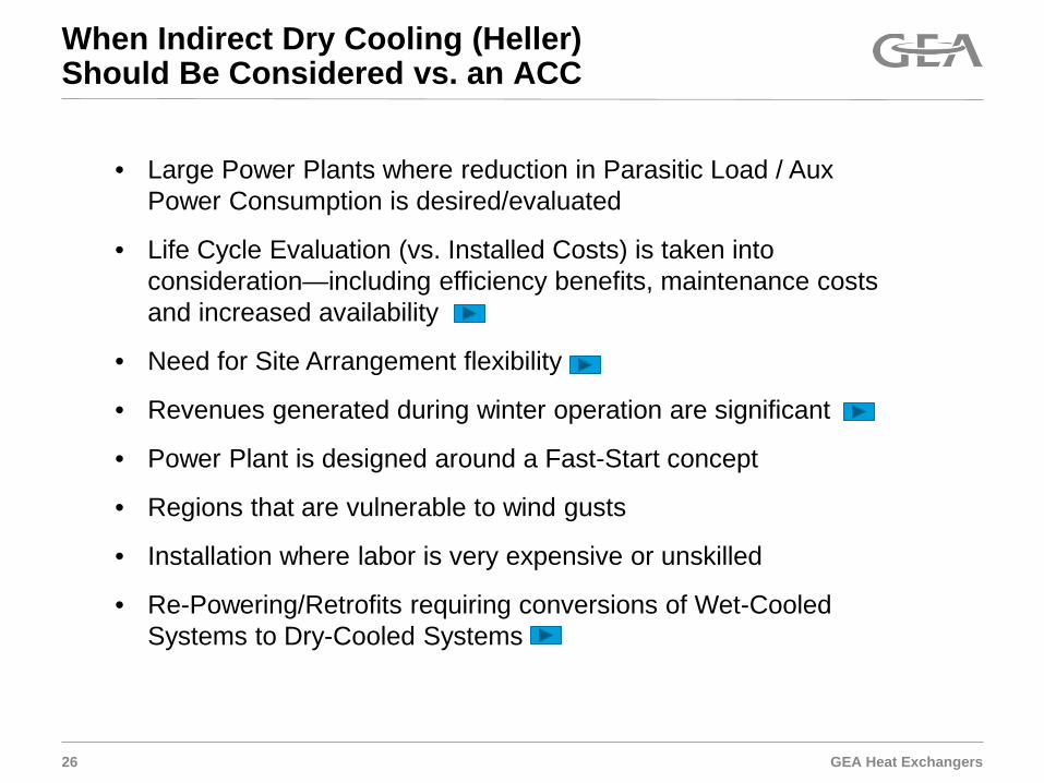
When Indirect Dry Cooling (Heller) Should Be Considered vs. an ACC
26
• Large Power Plants where reduction in Parasitic Load / Aux Power Consumption is desired/evaluated
• Life Cycle Evaluation (vs. Installed Costs) is taken into consideration—including efficiency benefits, maintenance costs and increased availability
• Need for Site Arrangement flexibility
• Revenues generated during winter operation are significant
• Power Plant is designed around a Fast-Start concept
• Regions that are vulnerable to wind gusts
• Installation where labor is very expensive or unskilled
• Re-Powering/Retrofits requiring conversions of Wet-Cooled Systems to Dry-Cooled Systems
GEA Heat Exchangers
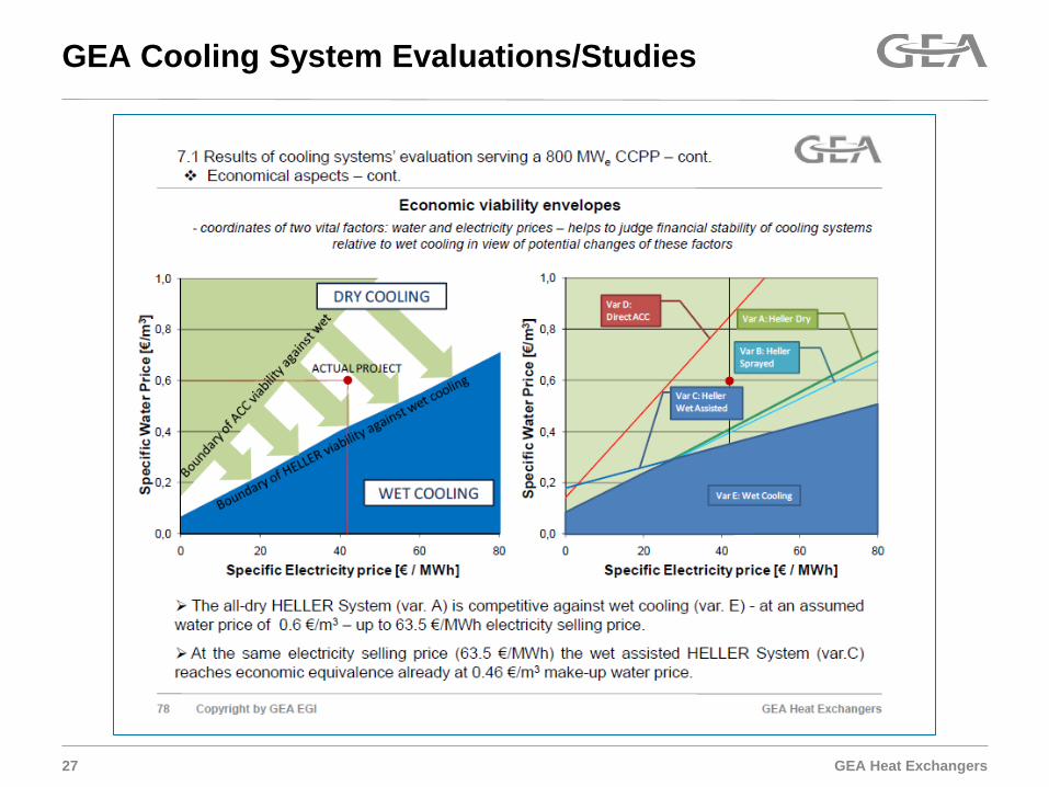
GEA Cooling System Evaluations/Studies
27

GEA Heat Exchangers
Appendices, Enclosures, Attachments, etc
29
GEA Heat Exchangers
Cold Condensing Capability
30
0
50
100
150
200
250
300
350
-20 -15 -10 -5 0 5 10 15 20 25 30 35 40
Turb
ine
back
-pre
ssur
e, m
bara
Ambient Dry Bulb Temperature, °C
COLD END HEAT DISSIPATION CAPABILITY AT FULL TURBINE LOAD(considering varying heat input into the steam-cycle)
All dry Heller SystemHeller System with SprayingHeller System with 2 wet cellsACCWET Cooling Tower

GEA Heat Exchangers
Noise Generation Study
31
Impact of cooling systems on noise emmission Sound pressure levels around the 800 MWe CCPP equipped with functionally
equivalent dry cooling systems: natural draft HELLER System and mechanical draft direct ACC :
Direct ACC HELLER System
90 ha occupied by noise > 45 dB(A) 54 ha occupied by noise > 45 dB(A)
GEA Heat Exchangers
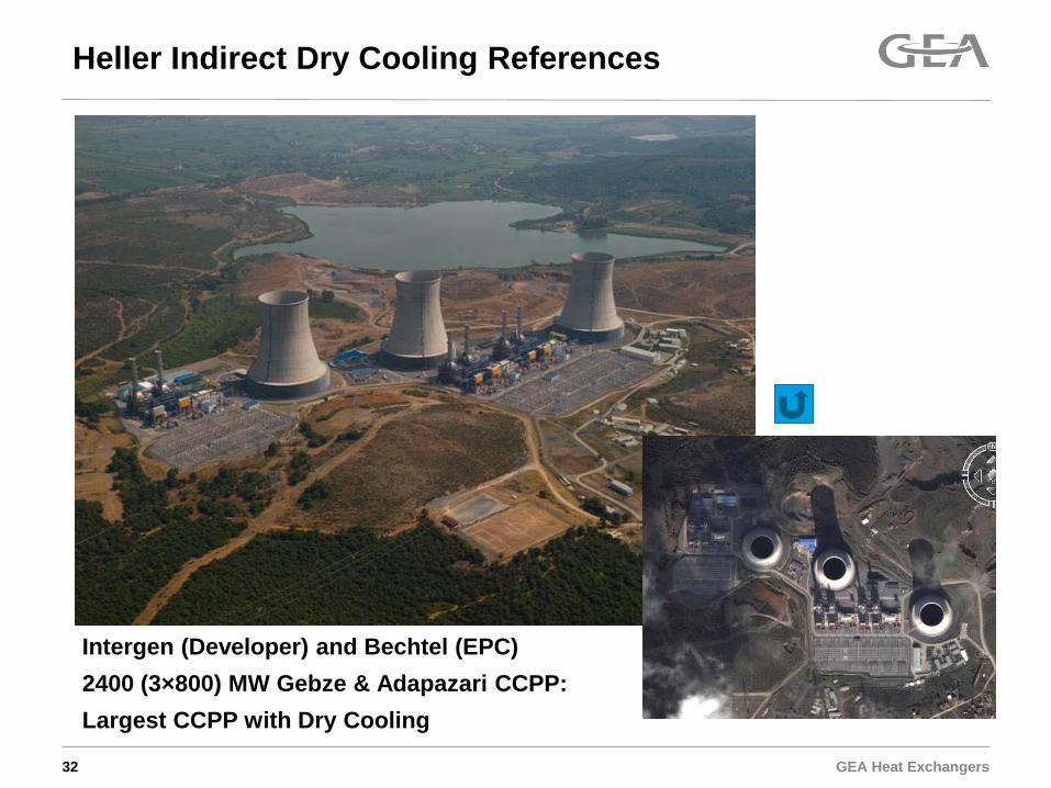
Intergen (Developer) and Bechtel (EPC) 2400 (3×800) MW Gebze & Adapazari CCPP: Largest CCPP with Dry Cooling
32
Heller Indirect Dry Cooling References

GEA Heat Exchangers
800 MWe Modugno CCPP, Italy (EPC: Alstom, owner: Energia SpA) Heller System with DC Jet condenser
No bypass stack for gas turbines, cooling system supports plant reliability
Select References, Mechanical Draft Heller Systems
24 main cooler cells with single fan 2 auxiliary cooler cells with four fans each
This document is proprietary to GEA EGI Contracting/Engineering Co. Ltd. All rights reserved.

GEA Heat Exchangers 34
Natural Draft Tower Design Flexibility
GEA Heat Exchangers
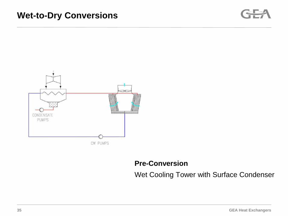
Wet-to-Dry Conversions
35
Pre-Conversion Wet Cooling Tower with Surface Condenser
GEA Heat Exchangers
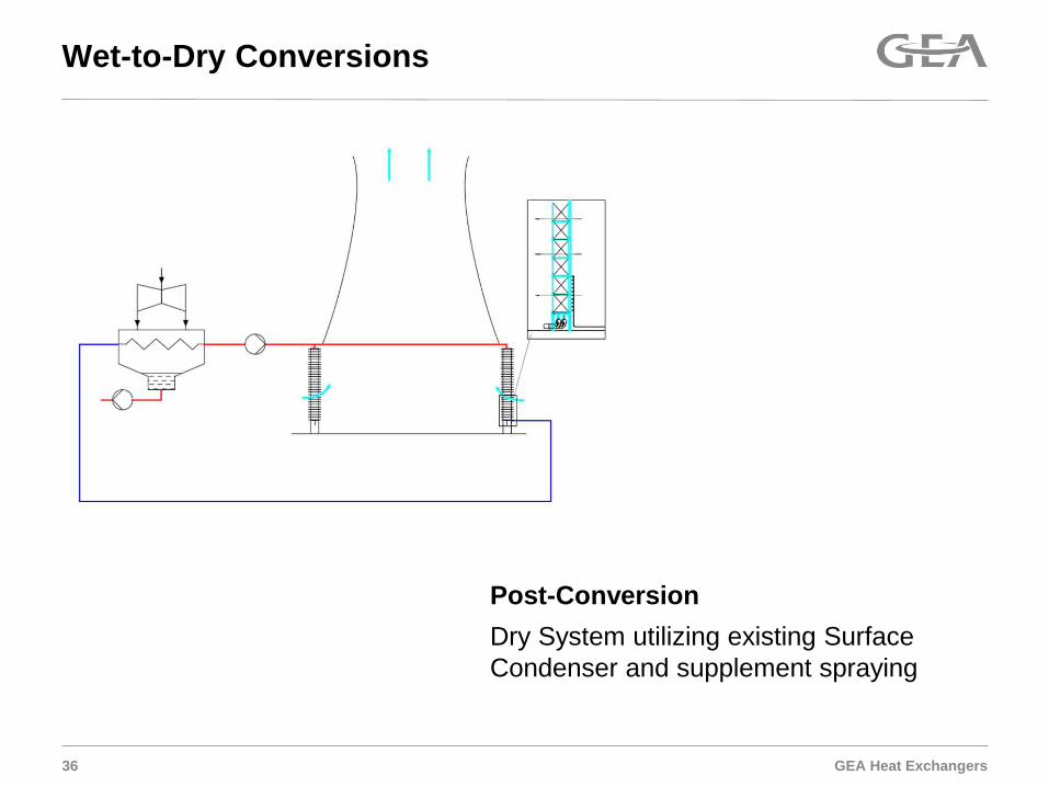
Wet-to-Dry Conversions
36
Post-Conversion Dry System utilizing existing Surface Condenser and supplement spraying
GEA Heat Exchangers
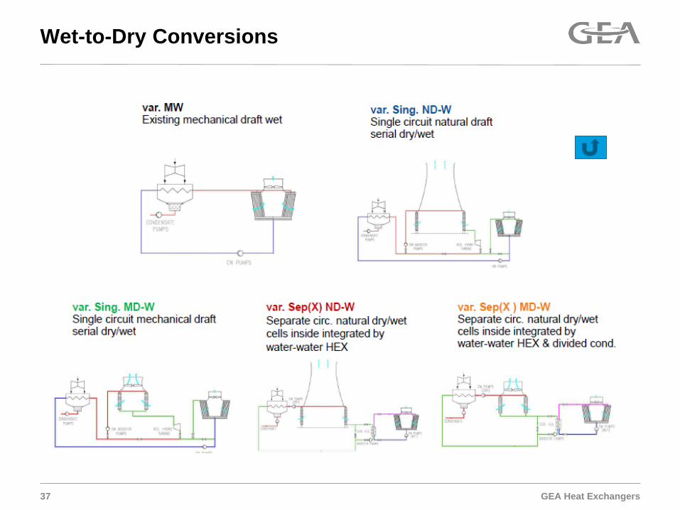
Wet-to-Dry Conversions
37