Embed Size (px)
Citation preview

i
NIST Technical Note 1751
Accelerated Weathering of Firefighter Protective Clothing Containing
Melamine Fiber Blends
Shonali Nazaré Shaun Flynn
Rick Davis Joannie Chin
http://dx.doi.org/10.6028/NIST.TN.1751

ii
NIST Technical Note 1751
Accelerated Weathering of Firefighter Protective Clothing Containing
Melamine Fiber Blends
Shonali Nazaré Shaun Flynn
Rick Davis Flammability Reduction Group
Fire Research Division Engineering Laboratory
Joannie Chin
Polymeric Materials Group Materials and Structural Systems Division
Engineering Laboratory
http://dx.doi.org/10.6028/NIST.TN.1751
August 2012
U.S. Department of Commerce Rebecca M. Blank, Acting Secretary
National Institute of Standards and Technology
Patrick D. Gallagher, Under Secretary of Commerce for Standards and Technology and Director
iii
Certain commercial entities, equipment, or materials may be identified in this document in order to describe an experimental procedure or concept adequately.
Such identification is not intended to imply recommendation or endorsement by the National Institute of Standards and Technology, nor is it intended to imply that the entities, materials, or equipment are necessarily the best available for the purpose.
National Institute of Standards and Technology Technical Note Natl. Inst. Stand. Techn. Techn. Report XXX, 37 pages (August 2012)
CODEN: NTNUE2

iv
Abstract In this study, the mechanical properties critical to the protective performance of firefighter turnout gear were evaluated in environmentally stressed outer shell (OS) fabrics containing melamine fiber blends. Environmental stress factors that affect the durability of turnout gear include temperature, ultraviolet (UV) radiation, moisture, abrasion, and laundering. The effect of fiber blend, fabric construction, and finishing processes including water repellent coatings and pigmented melamine- containing OS fabrics were also studied. Melamine-containing OS fabrics show comparable thermal protective performance and have superior tear resistance when compared to the traditionally used polyaramid blends. This study reveals that the thermal protective protection (TPP) rating of fabric assemblies incorporating environmentally stressed OS fabrics containing melamine fiber blends is well above the NFPA minimum TPP requirement of 35 Cal/cm2. However, the tear strength (measured using ASTM D 5587 standard test method ) of all melamine-containing OS fabrics exposed to environmental stresses was observed to have significantly deteriorated, and most OS fabrics, depending on fiber blend and fabric structure, would fail to meet requirements of NFPA 1971 standard. The study thus suggests that environmental stressing has a more detrimental impact on the tear strength than the thermal protective performance of OS fabrics. Deterioration in tear strength of all UV exposed OS fabrics is largely due to photodegradation of constituent fibers. Changes in tear strength of OS fabrics subjected to thermal exposures and laundering is cumulative effect of loss in tensile strength of single yarns and dimensional stability of the fabric itself. Furthermore, finishing treatments affect performance properties of fabric by increasing fiber packing factor in yarn, changing yarn crimp and yarn spacing thereby making dimensional changes to the fabric. Surface coatings alter tear resistance of fabric by influencing yarn slippage and fabric rigidity. Fabrics dyed with black and dark blue dyes cause less UV degradation of fibers than bright yellow and brown dyes. Keywords Accelerated weathering, UV irradiation, abrasion, laundering, heat exposures, fire fighter turnout gear, melamine fibers.

v
This page left intentionally blank.

vi
Contents List of Tables ............................................................................................................................... vii List of Figures ............................................................................................................................. viii List of Acronyms .......................................................................................................................... ix 1. Introduction ............................................................................................................................ 11 2. Experimental .......................................................................................................................... 12
2.1. Fabrics ............................................................................................................................ 12 2.2. Environmental stressing ................................................................................................. 13
2.2.1. UV aging ................................................................................................................. 13 2.2.2. Laundering .............................................................................................................. 13 2.2.3. Abrasion and wear .................................................................................................. 13 2.2.4. Heat exposures ........................................................................................................ 14
2.3. Mechanical testing ......................................................................................................... 14 2.3.1. Tear strength ........................................................................................................... 14 2.3.2. Tensile strength ....................................................................................................... 15
2.4. Thermal protective performance testing ........................................................................ 15 3. Results and Discussion ........................................................................................................... 17
3.1. Tear resistance ............................................................................................................... 17 3.2. Tensile strength of yarn ................................................................................................. 20 3.3. Thermal protective performance of fabric ensemble ..................................................... 21
4. Summary and Conclusions ................................................................................................... 24 5. References ............................................................................................................................... 35
vii
List of Tables Table 1. Description of outer shell fabrics. ............................................................................... 12 Table 2. Tear strength of OS fabrics containing melamine fiber blends. Uncertainties in measurement of tear strength are expressed as experimental standard deviations. ................... 18 Table 3. Tensile properties of yarns extracted from OS fabrics. Uncertainties in measurement of tensile strength are expressed as experimental standard deviations. ..................................... 20 Table 4. Protection time for OS fabrics containing melamine fiber blends. Uncertainties in measurement of time to second degree burn are expressed as experimental standard deviations..................................................................................................................................................... 22 Table 5. Percent reduction in TPP values: Individual and combined effects of environmental stressing on thermal protective performance of OS fabrics. ...................................................... 23

viii
List of Figures Figure 1. Schematic of: (a) Martindale type abrader and (b) modified assembly of Martindale type abrader. ............................................................................................................................... 26 Figure 2. Schematic of TPP test apparatus. .............................................................................. 27 Figure 3. Single tear fabric configuration [26]. ........................................................................ 28 Figure 4. Deterioration in tear strength of OS fabrics exposed to simulated UV radiation. Error bars are ± experimental standard deviation. ..................................................................... 30 Figure 5. Percentage reduction in tear strength of environmentally stressed OS fabrics. ........ 30 Figure 6. Deterioration in tensile strength of OS fabrics exposed to simulated UV radiation. Error bars are ± experimental standard deviation. ..................................................................... 32 Figure 7. Percentage reduction in tensile strength of yarn unraveled from environmentally stressed OS fabrics. .................................................................................................................... 33 Figure 8. Thermal protective performance of environmentally stressed OS fabrics. Error bars are ± experimental standard deviation. ...................................................................................... 34

ix
List of Acronyms AATCC American Association of Textile Chemists and Colorist ASTM ASTM International LbL Layer-by-Layer LOI Limiting Oxygen Index MB Moisture Barrier NC Natural Conditions exposure NFPA National Fire Protection Association NIST National Institute of Standards and Technology OS Outer Shell RH Relative Humidity SPHERE Simulated Photodegradation via High Energy Radiant Exposure TGC Turnout Gear Conditions TiO2 TL TPP
Titanium dioxide Thermal Liner Thermal protective performance
UPF Ultraviolet Protection Factor UV Ultraviolet

x
This page left intentionally blank.

11
1. Introduction Most turnout gear commonly used by firefighters in the United States is comprised of three layers, each performing a distinct function. The outer shell (OS) fabric provides flame protection and serves as a primary defense to mechanical injury, heat, and fire. The waterproof middle layer acts as a moisture barrier (MB), and the thermal liner (TL) which is next to the skin, provides thermal insulation and protects the wearer from burn injury. The outer shell fabric is predominantly made from fiber blends of poly(m-phenylene isophthalamide) (PPI), poly(p-phenylene terephthalamide) (PPT), polybenzimidazole (PBI), and polyphenylenebenzobisozazole (PBO). Selection of fiber type and blend ratios are often driven by cost. Very recently, melamine fibers are finding applications in high performance clothing. Heat resistance and thermal properties of these fibers are comparable to inherently fire resistant fibers traditionally used in OS fabrics. OS fabrics containing blends of aramid fibers have been studied in detail and extensively reported [1,2,3,4,5,6,7,8,9]. However, few studies have been carried out and reported in the literature on OS fabrics containing melamine fibers.
The melamine fibers, more accurately termed melamine-formaldehyde fibers, are produced via a condensation reaction between melamine and formaldehyde in a molar ratio of 2:1. Hydroxyoxaalkylmelamines and other additives are also utilized in small amounts. Melamine fibers have excellent heat resistance (e.g., limiting oxygen index (LOI) of 32 %, no melting, and high temperature strength retention) and have tenacity of 2.0 g/denier to 2.3 g/denier. High heat stability is primarily due to the cross-linked nature of the polymer. When exposed to heat/flame, the fibers char without shrinking. Melamine fibers are also known to be the most thermally-insulative fibers. Generally, thermal conductivity of inherently fire resistant fibers is high, however melamine fibers have the lowest thermal conductivity values (≈ 0.285 [W/ (m∙K)] ) amongst all inherently fire resistant fibers [10]. Because of their low tensile strength, melamine fibers are generally blended with stronger aramid fibers. At National Institute of Standards and Technology (NIST), we have been studying effects of accelerated weathering on performance of OS fabrics [7, 11]. The main aim of this study is to improve guidelines for the retirement of firefighters turnout gear. In the first phase of this work, accelerated weathering of polyaramid and polybenzimidazole outer shell (OS) fabrics was studied and reported [7]. OS fabrics were exposed to simulated ultraviolet (UV) radiation at 50 °C and 50 % relative humidity. The aging performance profile (APP), which is the deterioration of properties as a function of time, suggested that 13 d continuous exposure (equating to 6.6 years of turnout gear exposure to UV radiation under natural conditions of usage) to the conditions mentioned above caused significant deterioration in the mechanical performance of OS fabrics [7]. Environmental stress factors that affect the durability of turnout gear include temperature, UV radiation, moisture, abrasion, and laundering. Reported here is a study of the individual environmental stress factors on the performance metrics of OS fabrics containing melamine fibers. Environmental stress factors were reproduced at a laboratory level, simulating environmental stressing experienced during actual end-use conditions.

12
Environmentally stressed fabric samples were evaluated for thermal and mechanical properties that are critical to the protective performance of firefighter turnout gear.
2. Experimental1 2.1. Fabrics Four OS fabrics made from ring spun yarn consisting of 40 % melamine and 60 % para-aramid fibers were used in this study. Description of all four OS fabrics is given in Table 1. Fabrics varied in their physical properties as well as chemical finishes applied. Three OS fabrics (BK-00, BK and BBK) had similar fabric construction with a rip stop weave which is generally used to increase a fabric’s tear resistance and tensile properties. BKP has a basket weave with a rip stop yarn woven into the construction. BBK fabric having area density of 254 g/m2 has a durable fluorocarbon water repellant finish and is dyed black using acid dyes. BK is a slightly denser fabric with area density of 264 g/m2 and thickness of 0.66 mm. BKP is a blend of melamine (32 %), para-aramid (60 %) and uses proprietary core spun yarn (with polyphenylenebenzobisozazole (PBO) filament as core and poly(p-phenylene terephthalamide) in the sheath) as rip stop yarn. PBO fibers have superior tensile strength and high modulus, and are used as a reinforcing element. PBO also has a very high flame resistance and is self-extinguishing. LOI of PBO (68 %) is much higher than aramid fibres [ 12 ]. BK-00 has similar construction and fiber composition to BK except that BK-00 fabric is ‘gray’ fabric that has not been subjected to textile finishing processes. This selection of experimental fabrics allows us to study the effect of fiber blend, finishing processes including water repellent coating and pigmentation of melamine containing OS fabrics on protective performance of environmentally stressed OS fabrics. Table 1. Description of outer shell fabrics.
Fabric name
Fiber blend (%) Thickness, mm
Weight g/m2 (oz/yd2)
Fabric weave
Water repellant finish
Melamine Poly(p-phenylene terephthalamide)
Polyphenylene-benzobisozazole (PBO)
BK-00 40 60 - 0.66 264 (7.8) Plain/ Rip stop None BK 40 60 - 0.66 264 (7.8) Plain/ Rip stop Hypel+B2
BKP 32 60 8 0.78 264 (7.8) Basket weave/Rip stop Hypel+B2
BBK 40 60 - 0.54 254 (7.5) Plain/ Rip stop Durable water repellent finish
1 Certain commercial equipment, instruments or materials are identified in this paper in order to specify the
experimental procedure adequately. Such identification is not intended to imply recommendation or endorsement by the National Institute of Standards and Technology, nor is it intended to imply that the materials or equipment identified are necessarily the best available for this purpose.

13
2.2. Environmental stressing
2.2.1. UV aging
UV irradiation experiments were conducted as previously described [7]. Fabric specimens having approximate dimensions of 10.2 cm × 7.6 cm (4 in × 3 in) were exposed to high UV irradiance in the NIST integrating sphere-based weathering device, referred to as SPHERE (Simulated Photodegradation via High Energy Radiant Exposure). Accelerated exposure of the fabrics to high UV irradiance was carried out using the mercury arc lamp system that produced a collimated and highly uniform UV flux in the environmental chambers of the SPHERE. A borosilicate glass window was placed between the lamp system and the integrating sphere to eliminate all UV wavelengths < 290 nm. The dichroic reflector in the lamps removed wavelengths > 450 nm. Additional details on the construction and properties of the SPHERE have been published elsewhere [ 13]. The fabric samples were continuously exposed to a UV irradiance dosage of 15.9 kJ/m2 ± 0.02 kJ/m2 for prescribed periods of time. Based on the prescribed amount of UV exposure on the SPHERE, various parameters including continuous sun (CS) days (calculated number of days where sunlight is assumed for 24 h a day), natural conditions (NC) day calculated assuming 9 h of sunlight in a day and exposure period for turnout gear have been calculated and reported elsewhere [7].
2.2.2. Laundering
The OS fabrics having approximate dimensions of 380 mm x 380 mm (15 in x15 in) were subjected to 5 cycles of a washing and drying at Maryland Fire Equipment Corporation, Rockville, MD. To avoid fraying of the edges, Fray Check (Prime Consumer USA Inc.) glue was applied to the edges of the fabric pieces. Washing was carried out in an industrial washing machine at 40 oC using a wash cycle of approximately 1 h. Front loading automatic machines were used that do not utilize an agitator which is known to result in greater clothing “wear” during washing [14]. The 1993 AATCC Standard Reference Detergent which is specified in the NFPA 1971, Standard on Protective Ensembles for Structural Fire Fighting (2000 Edition) was used. The amount of detergent used was 5 g/L and the liquor (liquid containing water and detergent) ratio was 1:5. No other chemicals were used during washing. Fabric samples were dried on drying racks.
2.2.3. Abrasion and wear
In order to simulate wear and tear during use, OS fabrics were abraded on a Martindale abrader (James and Heal Co. Ltd, UK) which simulates the damage due to rubbing against another. Such a method is generally used to assess the abrasion resistance of textile materials. A schematic of the test apparatus is shown in Figure 1(a). In this study, the Martindale test method (DIN EN ISO 12947-3) [15] was modified to abrade a larger area of the fabric samples. A schematic of the modified test apparatus is shown in

14
Figure 1(b). Generally, according to the DIN EN ISO 12947-3 Martindale test method, circular fabric samples (38 mm diameter) are mounted in sample holders and are rubbed against a standard wool fabric. However, for this study, a 38 mm diameter specimen were not large enough to evaluate thermal protective performance and hence the position of the abrader (the standard wool fabric) and test sample were reversed (see Figure 1(b)). With the modified experimental set-up, it was possible to abrade larger areas of OS fabrics. The OS fabrics were abraded under a known pressure of 9 kPa and with the translational movement of the abrader tracing a Lissajous figure [ 16]. The rotational speed of the top moving plate was set at 47.5 revolutions per min with a maximum stroke length of 60.5 mm. With these operating parameters, an approximate area of 3660 mm2 was abraded. Each OS fabric specimen was subjected to 20, 000 rub cycles. None of the specimens showed signs of rupture following the test cycle.
2.2.4. Heat exposure
OS fabrics were exposed to convective heating according to ISO 17493 [17]. Fabric specimens having approximate dimensions of 380 mm x 380 mm (15 in x 15 in) were suspended in a convection oven by metal hooks such that the airflow was parallel to the plane of material. Two heat exposure conditions were chosen for this study: 260 oC for 5 min and 180 oC for 24 h. 2.3. Mechanical testing
2.3.1. Tear strength
NFPA 1971 Standard on Protective Ensembles for Structural Fire Fighting and Proximity Fire Fighting [18] requires testing tear resistance of OS fabrics using the test procedure described in ASTM D 5587 [19]. The standard describes measurement of tear strength by the trapezoidal method (an in-the-plane tear propagation). In the textile industry, this method is not frequently used as the stress pattern measured by this method is largely determined by variables at the disposition of the operator and the tear strength values are high since the fabric yarn is pulled, not torn, apart. For these reasons, the fabric tear resistance for this study was determined using the single tear method described in ASTM D 2261[20]. Moreover, it has been shown that changes in tear strengths due to fabric construction, finishing treatments, washing and weathering could be best determined by a rip test [21]. The single tear test (also called the rip tear test) is an out-of-the-plane tear that propagates at relatively low loads and results lower tear strength values as compared to trapezoidal tear test values. Both the single tear and trapezoidal tests simulate the tearing of fabric by hand [21]. The single tear tests were conducted on an Instron universal testing machine (model 5582, Instron Corp., Northwood, MA) equipped with 2 kN load cell and custom grips for fabrics. The gauge length between grips was 25 mm, and crosshead speed was 50 mm/sec. A single 25 mm (1.0 in) tear was introduced at one end of specimen having

15
approximate dimensions of 68 mm × 25 mm (2.66 in × 1.0 in). Tests were performed on OS fabrics cut along the warp direction (longitudinal tearing direction). Four replicates of each fabric were tested per sampling interval. Uncertainties in measurement of tear strength are reported as Type A uncertainties [22, 23] with experimental standard deviations in Table 2.
2.3.2. Tensile strength
Due to specimen size limitations, the tensile strengths of fabrics were based on yarn tensile strength values. The tensile strength or breaking strength of a fabric is generally greater than its tear strength. In the single tear test described above, each cross-section of yarn is subjected to progressively increasing tension. The cross-yarn fails singly, doubly or even in multiples, depending on the type of weave, yarn strength and elongation properties. It is important to note that in a tear test, the yarn fails individually in tension and for this reason the fabric tear strength is much lower than its breaking strength where all yarns fail at the same time. Thus, for a more precise understanding of fabric deterioration, the individual yarns extracted from fabrics exposed to various conditions were tested for tensile strength and breaking elongation. The yarn strength is the stress at which the yarn fails or fractures. Elongation at break is the increase in length produced by the breaking force, expressed as a percentage of the original nominal length. Since the properties depend on the specimen dimensions and testing conditions (e.g., strain rate and gauge length) the values are best used for relative comparison and not as absolute values to compare with results reported elsewhere. Due to the complexities in calculation of cross-sectional area of ply-twisted yarns with fiber blends, the breaking force and breaking strain values of extracted yarns are considered in this study. Tensile properties of ply-twisted yarn from fabric specimens were measured using a TA Instruments RSA III Dynamic Mechanical-Thermal Analyzer operating in transient mode (DMTA, TA Instruments-Waters LLC, New Castle, DE). Gauge length was 10 mm and specimen extension rate was 0.005 mm/s. Since the instrument is not equipped with an extensometer, the strain was calculated by the change in grip spacing. Therefore, the data represent trends and not absolute values. A minimum of five individual ply-twisted yarns was analyzed per sampling interval. Uncertainties in measurement of tensile strength are reported as Type A uncertainties [22, 23] with experimental standard deviations in Table 3. 2.4. Thermal protective performance testing A thermal protective performance (TPP) tester developed by Measurement Technology Northwest was used in this study to measure the thermal protective performance of environmentally stressed OS fabrics. A schematic of the test apparatus is shown in Figure 2. The instrument is based on the NFPA 1971 test standard and the test method uses data from Stoll and Chinta [24] to estimate the time it takes for second degree burn injury to the skin behind a fabric assembly when exposed to a given heat flux.

16
The test apparatus consists of two Meeker burners and bank of quartz tubes calibrated to provide 50 % radiative and 50 % convective heat flux. The test sample is exposed to a total heat flux of 84 kW m-2 ± 5 kW m-2 (2 cal cm-2 s-1± 0.1 cal cm-2 s-1). This exposure condition typically represents military fire flash conditions that are similar to emergencies encountered by firefighters [9]. The total heat flux was calibrated every day prior to experimentation. The Meeker burners were kept at an angle of 45o to the horizontal so that the flames converge at a point immediately under the test specimen. Burner flames were carefully monitored for any turbulence. The sample assembly consists of a frame for securing the fabric specimen and a heat sensor placed in direct contact with the back of the fabric assembly. The NFPA 1971 standard [18] requires inclusion of a spacer between the heat sensor and the back of the fabric assembly. Inclusion of the spacer in the sample assembly represents an air gap between the skin and the fabric and typically increases TPP rating due to the presence of the insulating air gap [8]. However, in this study the spacer was not used as it was found to detrimentally distort the results with some materials more than others [25]. The heat sensor consists of a copper calorimeter embedded in an insulating board which is placed face down on the fabric assembly. The copper calorimeter consists of a blackened copper disc of 40 mm diameter and has thickness of 1.6 mm. Three 32-gauge chromel/alumel thermocouples are mounted in the disk at 120° intervals. The heat sensor with calibrated copper calorimeter is connected to a ThermDac data acquisition system which records the rate of temperature rise of the sensor. The water-cooled shutter is pneumatically actuated and automated for precise control of exposure timing. It covers the heating elements so as to allow time for the sample carriage to move into position above the heat source. At the start of the test, the heat sensors are kept approximately below body temperature. The rise in temperature after the exposure is calculated by subtracting the starting temperature and the recorded temperature. The rate of temperature rise versus the time is used in conjunction with calorimeter constants to calculate heat flux received. The heat flux behind the test sample is translated into protection time using the Stoll criterion based on time-to-second degree burn [24]. Once the time-to-second degree burn is reached, the shutter closes and the test ends. The TPP rating of the fabric assembly is determined by multiplying the recorded protection time by the heat flux exposure. The higher the TPP rating, the better the thermal protective performance of the fabric assembly. Upon completion of the test, the sensors were carefully examined for any sticky residue or char from degraded sample. Any accumulated residues were carefully cleaned from the sensor and sample holder surfaces as well. Three specimens were tested for each sample. Uncertainties in measurement of exposure time to second degree burn and TPP values are reported as Type A uncertainties [22, 23] with experimental standard deviations in Table 3 and Figure 8 respectively.

17
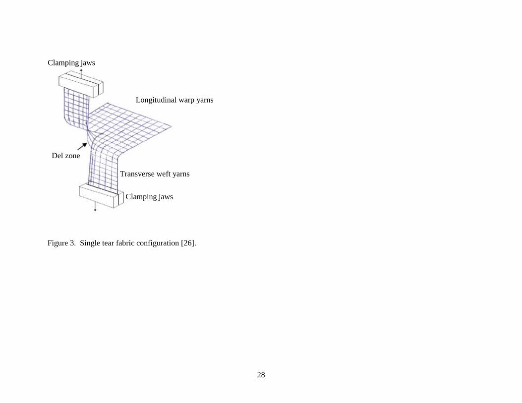
In order to evaluate the impact of environmental stressing of OS fabrics on thermal protective performance of protective ensemble, the moisture barrier (polytetrafluoroethylene-based film laminated to woven aramid substrate) and thermal liner (composite fabric consisting of a woven face fabric quilted to a spunlaced non-woven) were kept consistent in all test specimens. Fabric components tested were placed on the sample holder in the representative sequence encountered in turn-out gear, in that the OS is exposed to the heating elements and the thermal liner in contact with the sensor. This condition measures the barrier characteristic of the surface material and the insulation characteristics of the total assembly. 3. Results and Discussion 3.1. Tear resistance The mechanism of tearing in woven structures generally includes four main stages: (1) the stretching and slippage of longitudinal yarns closest to the tip of the crack; (2), the crowding of these longitudinal yarns on the edges of a Del zone (see Figure 3) [26] and the transfer of the load to the transversal yarns held in tension in the so-formed Del zone; (3), the stretching and alignment/jamming of these transverse yarns; and (4) finally the rupture of the outer transverse yarn [27]. These stages proceed cyclically until the whole sample has failed. A typical tear test load-extension plot has a saw-tooth shape. The peaks in the force–displacement curve correspond to failure of each successive transverse yarn as the tearing progresses. The middle part of the load-extension curve represents 50 % of the entire tear distance. For a given sample, determining tear resistance by static single tear test method (ASTM D2261) relies on determining the median of the five largest tear forces from the middle part of the load-extension curve. Tear strength values for experimental OS fabrics are provided in Table 2. Tear strength of untreated BK-00 fabric has the highest tear strength value of 175 N ± 10 N. The lower yarn density in BK-00 allows greater yarn mobility and therefore increased tear strength. Since BK-00 has not been subjected to textile finishing processes, which essentially includes wetting and drying, the loose fabric structure with lower yarn density allows greater yarn mobility as compared to BK fabric. The BK fabric that has been modified by finishing process and surface treatments has the lowest tear strength value of 88 N ± 5 N. Finishing treatments can affect tearing strength by altering single yarn strength, ease of slippage, fabric rigidity, and possibly by influencing structural properties as yarn spacing and yarn crimp [21]. Higher packing density of yarns in BK fabric as compared to BK-00 decreases longitudinal yarn mobility leading to a more rapid crowding of the yarns in the Del zone. The number of transverse yarns in the Del zone, which support the applied load, is thus reduced. However, this trend is not straightforward and discrepancies may arise due to differences in the failure mechanisms [28]. The slightly higher tear strength value for BKP (113 N ± 6 N) as compared to BK fabric can be attributed to the presence of PBO fibers in the fabric blend and the weave of the fabric. The basket weave in BKP fabric has longer yarn floats and is known to resist tearing

18
[21]. The pigmented BBK fabric has tear strength of 110 N ± 6 N which is slightly higher than BK fabric. The small difference in tear strength values despite similar fiber blend and fabric structures may be attributed to differences in coatings and the stiffness it imparts to the final finished fabric. Considering reduced tear strength values when tested using the single tear method, all OS fabrics containing melamine fiber blends would meet the tear strength requirement (tear strength >100 N) specified in NFPA 1971 standard [18]. Table 2. Tear strength of OS fabrics containing melamine fiber blends. Uncertainties in measurement of tear strength are expressed as experimental standard deviations.
Exposure conditions Tear strength, N BK-00 BK BKP BBK Control
175±10 88±5 113±6 110±6
Heat exposure At 240 oC for 5 min
128±8 (-27%)
79±3 (-18%)
96±7 (-18%)
88±10 (-20%)
Heat exposure At 180 oC for 24 hrs
100±9 (-51%)
93±6 (-21%)
94±5 (-25%)
109±6 (-15%)
UV exposure, 13 days 13±1 (-93%)
12±2 (-88%)
26±2 (-80%)
42 ± 3 (-62%)
Laundering
112±7 (-36%)
92±9 (-5%)
120±11 ( 3%)
109±9 (0 %)
Abraded - - - - Note: Values in parentheses indicate % change in tear strength w.r.t. control sample. Negative values indicate decrease in tear strength w.r.t. control sample and positive values indicate enhanced tear strength. 3.1.1. Impact of environmental stressing on tear strength of OS fabrics The ageing performance profiles (APP), which is the deterioration of property as a function of UV exposure time, for melamine containing OS fabrics are shown in Figure 4. The tear strengths of all melamine containing OS fabrics were significantly deteriorated when exposed to UV irradiation for 13 d ± 1 d at 50 oC and 50 % RH and would certainly not meet requirements of the NFPA 1971 standard. UV irradiation for 13 d ± 1 d typically corresponds to UV aging that a turnout gear would experience during a ≈ 6 years period of use. This time period also corresponds to maximum degradation noted on the aging performance profile of previously studied aramid OS fabrics [7]. BK-00 fabric shows highest deterioration (93 %) in tear strength primarily because BK-00 fabric is untreated (no water repellent coating) and therefore UV degradation of constituent fibers/yarns is much greater than those with water repellent coatings. The water repellant coating shields the underlying fibers from direct irradiation thereby causing less UV degradation. BBK fabric shows the least deterioration in tear resistance

19
(62 %), possibly due to the greater UV resistance of dark shaded BBK fabric. Fabrics dyed with black and dark blue are known to disrupt ultraviolet radiation [29] thereby causing less UV degradation of fibers. Deterioration in tearing strength of all UV exposed OS fabrics is largely due to photodegradation of constituent fibers [7]. Heat exposures were observed to have a small detrimental effect on tear strength of OS fabrics tested in this study (Table 2). Heat exposure at 260 oC for 5 min reduced tear resistance of all OS fabrics by ≈ 10 %. Heat exposure at 260 oC for 5 min has practically same effect as heat setting process on fabric. Prolonged exposures (24 h) to 180 oC had varied impact on all four OS fabrics. Tear strength of BK-00 fabric decreased by ≈ 30 %. This ‘gray’ fabric shrinks considerably to increase yarn density thereby reducing its tear strength. The very slight observed increase in tear strength of BK fabric exposed to 180 oC for 24 h can be attributed to loss in stiffness of the fabric as a result of prolonged heat exposure. Water repellent coating imparts stiffness to the fabrics which restricts yarn mobility in the fabric structure. The water repellent coating is slightly degraded during prolonged heat exposures thereby relaxing the yarns and increasing their mobility. As discussed earlier, increased yarn mobility in the Del zone increases the tear strength of a fabric. BBK fabric which is similar to BK, except the pigmentation, shows very slight deterioration in tear strength but has significant discoloration due to prolonged heat exposure. In this study, the laundering and drying process has considerable impact on tear resistance of BK-00 fabric. Untreated BK-00 fabric lost ≈ 20% of its tear strength when subjected to 5 cycles of washing and drying. This damage is dominant in BK-00 fabric with no surface coating. On the contrary, BK and BKP fabrics show slight improvement in tear strength. Increased tear strength of these fabrics may be due to improved flexibility and relaxation of yarns in the fabric structure. This essentially increases yarn mobility and thereby the tear resistance of fabrics. Laundering may have caused damage to fibers and yarns in the fabric due to mechanical agitation and chemical action of the detergent. When subjected to routine and repetitive laundering drying cycles, a piece of fabric is subjected to complex physical and chemical actions resulting in physical and chemical degradation of fabric [30]. Changes in the tear strength of washed OS fabrics could be due to the combined effect of dimensional changes of a fabric, increased fiber packing factor in yarn, and fiber damage due to physical and chemical actions during washing. OS fabrics with a suitable surface coating tend to stabilize and gain dimensional stability after the first washing cycle, resulting in improved tear resistance. In addition to dimensional changes in the fabric, the effects of washing on tear strength may arise from removal of certain types of finish that have detrimental effect on tearing strength, or from lubrication of the fabric by residual detergent. The magnitude of the effect in any particular case will depend on the extent to which these factors are operative. Percentage reduction in the tear strength of OS fabrics subjected to various environmental stresses is graphically shown in Figure 5. It is clear that UV exposure has the greatest impact on tear resistance of OS fabrics which is mainly due to photodegradation of constituent fibers [7]. Heat exposures have minimal impact on tear strength of OS

20
fabrics. Changes in tear strength of heat exposed and laundered OS fabrics are largely due to dimensional changes in fabric properties (e.g., area density, thickness, flexibility). Due to sample limitations, the impact of abrasive wear on tear strength of OS fabrics was not quantified in this study. 3.2. Tensile strength of yarn The tear strength of a fabric is largely governed by the single-yarn strength and slippage of yarn during the test. The slippage of yarn is dependent on spacing of yarn, weave and surface finish [21]. From the above discussion, it is clear that changes in tear strength of OS fabrics could be a combined effect of reduced yarn strength and dimensional changes in the fabric. To delineate the cause(s) of tear strength deterioration due to environmental stressing, changes in single-yarn strength are discussed in this section. Breaking force and breaking strain values for yarns extracted from OS fabrics are given in Table 3. Table 3. Tensile properties of yarns extracted from OS fabrics. Uncertainties in measurement of tensile strength are expressed as experimental standard deviations.
Note: Values in parentheses indicate % change in tensile properties w.r.t. control sample. Negative values indicate decrease in tensile properties w.r.t. control sample and positive values indicate enhanced tensile properties.
Exposure conditions BK-00 BK BKP
Breaking force, g
%- Breaking strain
Breaking force, g
%- Breaking strain
Breaking force, g
%-Breaking strain
Control 2930±250 13±4 2210±280 15±4 1520±190 11±1 Heat exposed at 260 oC for 5 min
2840±290 (-3%)
14±3 (+8%)
1920±280 (-13%)
15±2 (0%)
1250±130 (-18%)
12 ±2 (+9%)
Heat exposed at 180 oC for 24 h
2200±210 (-25%)
14±3 (+8%)
1990±210 (-10%)
14±1 (-7%)
1500±60 (-1%)
13±2 (+18%)
Laundering 2860±330 (-2%)
13±2 (0%)
2170±280 (-2%)
13±4 (-13%)
1630±260 (+7%)
7 ±1 (-36%)
UV exposure (d) 1±0.5 2110±290 (-28%)
10±1 (-23%)
2000±330 (- 9%)
15±4 (0%)
1590±110 (+5%)
11±0.3 (0%)
4±0.5 530±50 (-82%)
8±2 (-38%)
730±30 (- 67%)
11±0.2 (-27%)
620±80 (- 59%)
8±2 (-27%)
7±0.5 400±40 (-86%)
8±2 (-38%)
520±80 (- 77%)
14±2 (-7%)
430±60 (- 72%)
8±2 (-27%)
13±0.5 200± 30 (-93%)
7±2 (-46%)
260±80 (-88%)
11±2 (-27%)
190±20 (-87%)
8±2 (-27%)
28±0.5 150±30 (-95%)
8±2 (-38%)
170±20 (- 92%)
10±1 (-33%)
130±20 (- 91%)
7±1 (-36%)
21
Within the measurement uncertainty, single yarn strength of BK-00 in tensile test is similar to that of BK. Despite inclusion of high tenacity PBO fibers, the overall tensile strength of BKP yarns is lower than that of BK-00 and BK yarns. All the fibers displayed somewhat brittle failure with average breaking strain of 15 % ± 4 %. Since para-aramid fibers constitute the majority (60 %) of BK-00, BK and BKP yarns, their tensile properties are mainly dominated by the highly oriented structure of poly(p-phenylene terephthalamide) [11]. Comparing the APP of yarns in Figure 6, it can be noted that all the yarns rapidly lose tensile strength upon UV exposure. BK-00 yarns lost more than 90 % of their initial tensile strength after 13 d of continuous exposure to UV radiation while BK and BKP lost > 85 % of initial strength. Similar to trends observed for tear strength, further exposure up to 28 d resulted in continued deterioration of tensile strength at a significantly slower rate. All the yarns retained less than 10 % of its original strength at the end of 28 d exposure to UV/50oC/50%RH. The UV exposure also changed tensile behavior of BK-00 and BKP yarns from brittle failure (% breaking strain of 13 % ± 4 %) to very brittle failure (% breaking strain of 8 % ± 2 %). Yarns from BK OS fabric, however, did not show any change in their failure mechanism. Tensile properties of yarns extracted from fabrics exposed to other environmental stresses including heat exposures and laundering are given in Table 3 and percentage loss of tensile strength with respect to unexposed control specimens for BK-00, BK and BKP OS fabrics is plotted in Figure 7. It can be noted from Figure 7 that UV exposure has maximum impact on tensile properties of all yarns. Heat exposures have a small detrimental effect on tensile properties of all yarns. Laundering has a variable effect on tensile properties of yarns tested in this study. Yarns from BK-00 and BK OS fabrics show very small loss of tensile strength while yarns from BKP OS fabric show increase in tensile strength. This small increase in breaking force can be attributed to shrinkage of yarn and increased packing density of fibers in BKP yarn. Comparing percentage loss of tear strength and tensile strength in Figure 5 and Figure 7, it is clear that loss in tear strength of OS fabrics is slightly greater than the loss in tensile strength of single yarn extracted from OS fabrics. This suggests that changes in tear strength of OS fabrics are a cumulative effect of loss in tensile strength of single yarns and dimensional stability of the fabric itself. 3.3. Thermal protective performance of fabric ensemble Several researchers have studied the thermal protective performance of various fabric assemblies including single-layer OS fabrics as well as effects of instrumentation. King et al [31] measured the relative TPP of a wide range of flame-retardant (FR) fabrics, both in single and multiple layers. Their studies suggested that high density fabrics with FR fibers and FR finishes provide additional protection and that more protection is obtained by using two or more layers of fabrics as opposed to thicker fabrics. Moreover, two layers are effective only when both layers contain fabrics that do not melt and fuse together. They also classified fabrics on the basis of failure mechanism. The FR cotton

22
typically failed due to embrittlement and shrinkage while most wool containing fabrics failed via melting and decomposition. Glass and aluminum containing fabrics failed due to discoloration and embrittlement. Barker et al [32] studied the influence of fiber composition and fabric construction on the thermal protective performance in high intensity tests. They measured insulation properties of fabrics via conductive heat transfer and found that in such type of tests, the temperature of the hot surface and the pressure applied during the exposure are controlling test variables. Above 300 oC, the insulative performance of some fabrics deteriorates significantly due to heat degradation that causes changes in physical properties. Day [ 33 ] studied effect of nature of heat sources (radiative and/or convective) on measurement of TPP of fabrics assemblies. The 50/50 or 70/30 convective/radiative heat fluxes have very little impact on determining the heat transfer properties of garment assemblies. However, the specimen mounting has significant impact on TPP ratings. The additional weights, restraining pins, and air gap affects thermal shrinkage, thereby affecting TPP ratings. The study also revealed that the NFPA values were always higher than those obtained with the ASTM techniques. This difference in TPP values was not due to the difference in radiative to convective heat ratio but due to greater sagging of specimen into the larger opening of the sample holder in the NFPA method.
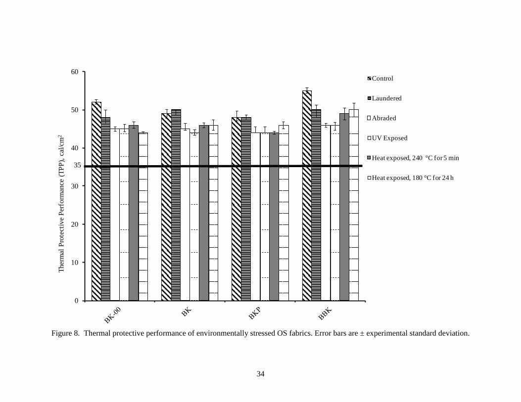
The thermal protective performance of fabric assemblies including OS fabrics containing melamine fibers were measured in this study. The exposure times to second degree burn for all OS fabrics are given in Table 4 and their thermal protective performance ratings are plotted in Figure 8. Generally, thermal protective performance of melamine containing OS fabrics is comparable to that of OS fabrics traditionally made from aramid and PBI fibers or their blends and is well above the NFPA minimum TPP requirement of 35 cal/cm2. Within the experimental error, the TPP rating (55 cal/cm2 ± 0.9 cal/cm2) of BBK is highest amongst the melamine containing OS fabrics, providing the wearer the maximum protection time of 27 s ± 0.43 s. BKP has a lower TPP rating (48 cal/cm2 ± 0.9 cal/cm2), giving a maximum protection time of 24 s ± 0.88 s. The lower thermal protective performance of BKP fabric could be due to the greater fabric thickness and/or to the presence of the highly conductive PBO fibers. Furthermore, compact construction with basket weave in BKP fabric may also increase heat transfer by conduction [8]. Table 4. Protection time for OS fabrics containing melamine fiber blends. Uncertainties in measurement of time to second degree burn are expressed as experimental standard deviations.
Exposure conditions Time to second degree burn, s
BK-00 BK
BKP
BBK
Control 25.8 ± 0.3 24.5 ± 0.6 24.1 ± 0.9 27.6 ± 0.4

23
Heat exposure At 240 oC for 5 min
22.6 ± 0.4 22.7 ± 0.3 21.9 ± 0.2 24.1 ± 0.8
Heat exposure At 180 oC for 24 hrs
22.0 ± 0.1 23.0 ± 0.7 22.86 ± 0.5 24.8 ± 0.9
UV exposure, 13 d on SPHERE
23.4 ± 0.4
22.3 ± 0.4 22.5 ± 0.8 22.7 ± 0.7
Laundering
24.1± 0.9 24.7 ± 0.2 23.9 ± 0.5 24.8 ± 0.6
Abraded 22.3 ± 0.3 22.3 ± 0.7 22.24 ± 0.8 23.2 ± 0.3 Figure 8 shows a comparison of the thermal protective performance ratings of environmentally stressed OS fabrics. Generally, the TPP ratings of environmentally stressed fabrics are lower than their respective control OS fabrics. However, the TPP ratings of all environmentally stressed fabrics still meet the NFPA minimum requirement of 35 cal/cm2. Amongst the environmental stressing factors, abrasion and UV exposure have the most detrimental effect on thermal protective performance of all OS fabrics tested in this study. All test assemblies with abraded and UV exposed OS fabrics had almost similar (45 cal/cm2± 1 cal/cm2) TPP ratings. This suggests that chemical and physical degradation of yarn and constituent fibers due to UV exposure and abrasion respectively have detrimental effects on thermal barrier properties of OS fabric. Heat exposure and washing seem to have very little effect on TPP rating of OS fabrics. Changes in the TPP ratings of washed and heat exposed fabrics could be due to the combined effects of dimensional changes in fabrics as well as degradation of constituent fibers and surface properties. In conclusion, the detrimental effect of environmental stressing on thermal protective performance could be ranked as: washing < heat exposure < abrasion< UV exposure. Table 5. Percent reduction in TPP values: Individual and combined effects of environmental stressing on thermal protective performance of OS fabrics.
OS fabric
Laundering
Abraded UV exposure, 13 d on SPHERE
Heat exposure At 240 oC for 5 min
Heat exposure At 180 oC for 24 hrs
% Average reduction in TPP
% Cumulative reduction in TPP
Calculated TPP value of OS fabric subjected to all environmental stressing, cal/cm2
BK-00 8 13 13 12 15 12 62 20 BK -2 8 10 6 6 6 29 35 BKP 0 8 8 8 4 6 29 34 BBK 9 16 16 11 9 12 62 21
Presented in Table 5 are percent reductions in TPP values of various OS fabrics due to each individual environmental stressing factor. Based on this information, average and cumulative effects of environmental stressing on thermal protective performance of various OS fabrics have been calculated and presented in Table 5. It can be noted from Table 5 that averaging the detrimental effects of all stressing factors, BK-00 and BBK

24
shows highest percent reduction ( 12 % w.r.t. control fabrics) while BK and BKP has lowest percent reduction ( 6 % w.r.t. control fabrics) in TPP values. Furthermore, presuming OS fabrics to have experienced all types of environmental stressing, then the cumulative detrimental effect on thermal protective performance can be estimated by simple addition of percent reductions in TPP values due to individual stressing. From the calculated TPP value of OS fabric subjected to all environmental stressing in Table 5 it can be seen that fabric ensemble with BK and BKP ( considering given experimental uncertainties ) outer shell will still meet the NFPA minimum TPP requirement of 35 Cal/cm2. However, fabric ensembles with BK-00 and BBK outer shells would fail to meet the requirements of NFPA 1971 standard. 4. Summary and Conclusions In this study, environmentally stressed OS fabrics containing melamine fiber blends were evaluated for thermal and mechanical properties that are critical to the protective performance of firefighter turnout gear. The effects of fiber blend, fabric construction, and finishing processes including water repellent coating and pigmentation of melamine- containing OS fabrics were also studied. The melamine-containing OS fabrics showed comparable thermal protective performance and superior tear resistance when compared to the traditionally used polyaramid blends. All the OS fabrics examined in this study performed well above the requirements of NFPA 1971 specifications. Results suggest that post-processing of ‘gray’ fabric which includes application of various finishes and coatings have significant impact on both, thermal protective performance and tear resistance of OS fabrics. Finishing treatments affected performance properties of fabric by increasing the fiber packing factor in yarn, changing yarn crimp and changing yarn spacing thereby making dimensional changes to the fabric. Surface coatings altered tear resistance of fabric by influencing yarn slippage and fabric rigidity. Fabrics dyed with black and dark blue dyes caused less UV degradation of fibers than bright yellow and brown dyes. Individual environmental stressing has varied impact on protective performance of OS fabrics. However, cumulative detrimental effect of all the stressing factors on thermal protective performance is maximum on BK-00 and BBK outer shell fabrics. UV exposure in particular causes more impairment of OS fabric as compared to other environmental stressing. Deterioration in tear strength of all UV exposed OS fabrics is largely due to photodegradation of constituent fibers. In cases where environmental stressing alters dimensional properties of a fabric including mass area density, thickness and flexibility, its effect on tear resistance of OS fabrics is a cumulative effect of loss in tensile strength of single yarns and dimensional stability of the fabric itself. The tear strength of all melamine containing OS fabrics exposed to environmental stressing has significantly deteriorated, and most OS fabrics, depending on fiber blend and fabric structure, would fail to meet requirements of NFPA 1971 standard. However, the TPP ratings of environmentally stressed OS fabrics containing melamine fiber blends are well above the NFPA minimum TPP requirement of 35 cal/cm2. The study thus suggests that environmental stressing has a more detrimental impact on tear strength than on the thermal protective performance of OS fabrics.
25
To mitigate the detrimental effects of UV, we are currently investigating a novel coating method using a layer-by-layer (LbL) deposition to fabricate nanometer- to micrometer-thick TiO2 coatings on the high performing fiber fabrics. The LbL coated fabrics will be evaluated for thermal and mechanical properties that are critical to the protective performance of firefighter turnout gear. The performance of LbL coated fabrics exposed to accelerated environmental stressing including UV exposure, laundering, wear and abrasion will also be evaluated.

26
Figure 1. Schematic of: (a) Martindale type abrader and (b) modified assembly of Martindale type abrader.
Top moving plate
Top weight
Sample holder
Abrasive cloth holder Machine base
Top moving plate
Top weight
Abrasive cloth holder
Sample holder Machine base

27
Figure 2. Schematic of TPP test apparatus.
Radiant heater
Gas burners Gas burners
Shutter Shutter
Sample carriage
Sample holder
Thermocouple
Sample
Calorimeter assembly
28
Figure 3. Single tear fabric configuration [26].
Longitudinal warp yarns
Clamping jaws
Transverse weft yarns
Clamping jaws
Del zone

29
0
50
100
150
200
250
Control 1 day 4 days 7 days 13 days 28 days
Tear
stre
ngth
, N
BK-00
BK
BKP
BBK

30
Figure 4. Deterioration in tear strength of OS fabrics exposed to simulated UV radiation. Error bars are ± experimental standard deviation.
Note: Negative values indicate loss of tear strength. Figure 5. Percentage reduction in tear strength of environmentally stressed OS fabrics.

31
0
500
1000
1500
2000
2500
3000
3500
Control 1 day 4 days 7 days 13 days 28 days
Bre
akin
g fo
rce,
g
BK-00
BK
BKP

32
Figure 6. Deterioration in tensile strength of OS fabrics exposed to simulated UV radiation. Error bars are ± experimental standard deviation.

33
Note: Negative values indicate loss in tensile strength.
Figure 7. Percentage reduction in tensile strength of yarn unraveled from environmentally stressed OS fabrics.
34
Figure 8. Thermal protective performance of environmentally stressed OS fabrics. Error bars are ± experimental standard deviation.
0
10
20
30
40
50
60Th
erm
al P
rote
ctiv
e Pe
rfor
man
ce (T
PP),
cal/c
m2
Control
Laundered
Abraded
UV Exposed
Heat exposed, 240 °C for 5 min
Heat exposed, 180 °C for 24 h
35

35
5. References [1] Barker RL, Geshury AJ, and Behnke WP. The effect of Nomex® /Kevlar® fiber
blend ratio and fabric weight on fabric performance in static and dynamic TPP tests. Performance of protective clothing: Fifth volume, ASTM STP 1237, J.S. Johnson and S.Z. Mansdorf, Eds., American Society for Testing and Materials, Philadelphia, (1996) pp 575-591.
[2] Arrieta C, David É, Dolez P, Khanh T V. Hydrolytic and photochemical aging studies of a Kevlar®-PBI blend. Polymer Degradation and Stability, 96( 8): 2011, pp 1411-1419
[3] Hirschler MM. Analysis of thermal performance of two fabrics intended for use as protective clothing, Fire and Materials 1997; 21:115–121.
[4] Sinclair W J. Flame resistant aramids. Business Communications Company Conference on Recent Advances in Flame Retardancy of Polymeric Materials, 15-17 May 1990, Stamford, CT, ed. by G.S. Kirshenbaum and M. Lewin, pp. 200-12, Norwalk, CT (1990).
[5] Lee YM, and Barker RL. Effect of moisture on the thermal protective performance of heat-resistant fabrics, Journal of Fire Sciences 1986; 4(5): 315-331.
[6] Crown EM, Dale JD and Bitner E. A comparative analysis of protocols for measuring heat transmission through flame resistant materials: capturing the effects of thermal shrinkage , Fire and Materials 2002; 26 (4-5): 207–213.
[7] Davis R, Chin J, Lin C, Petit S. Accelerated weathering of polyaramid and polybenzimidazole firefighter protective clothing fabrics, Polymer degradation stability 2010; 95: 1642-2654.
[8] Kutlu B, Cireli A. Thermal analysis and performance properties of thermal protective clothing, Fibers and Textiles in Eastern Europe 2005; 13 (3):58-62
[9] Cui Z, and Zhang W. Study of the effect of material assembly on the moisture and thermal protective performance of firefighter clothing, Fibers and Textiles in Eastern Europe 2009; 17 (6):80-83.
[10] www.basofil.com/about.html [11] Nazare S, Davis R, Peng JS and Chin J. Accelerated weathering of firefighter
protective clothing: Delineating the impact of thermal, moisture, and ultraviolet light exposures, NIST TN 911077, June 2012. National Institute of Standards and Technology, Gaithersburg MD.
[12] Bourbigot S, and Flambard X. Heat resistance and flammability of high performance fibers: A Review, Fire and Materials 2002; 26 (4-5): 155–168.
[13] Chin J, Byrd E, Embree N, Garver J, Dickens B, Finn T, Martin J. Accelerated UV weathering device based on integrating sphere technology. Review of Scientific Instruments 2004; 75: 4951.
[14] Laurent J B, Buzzaccarini F, Clerck K, Demeyere H, Labeque R, Lodewick R, Langenhove L. Laundry cleaning of textiles, in Handbook for Cleaning/Decontamination of Surfaces 2007; 1:57–102.
[15] EN ISO 12947-1:1998, Textiles-Determination of the abrasion resistance of fabrics by the Martindale Method. Part 1. Martindale Abrasion Testing Apparatus.

36
[16] Wang XY, Gong RH, Dong Z, Porat I. Abrasion resistance of thermally bonded
3D nonwoven fabrics, Wear 2007; 262(3-4): 424-431. [17] ISO 17493 Clothing and equipment for protection against heat-Test method for
convective heat resistance using a hot air circulating oven. [18] NFPA 1971: Standard on protective ensembles for structural fire fighting and
proximity fire fighting. National Fire Protection Association, Quincy, Massachusetts , 2007 Edition.
[19] ASTM D 5587 Standard test method for the tearing strength of fabrics by trapezoidal method.
[20] ASTM D2261 - Standard test method for tearing strength of fabrics by the tongue (single rip) procedure (constant-rate-of-extension tensile testing machine).
[21] Harrison P.W., The tearing strength of fabrics I. A review of the literature, Journal of Textile Institute 1960; 51 (1): T91-T131.
[22] Taylor BN and Kuyatt CE, Guidelines for Evaluating and Expressing the Uncertainty of NIST Measurement Results, NIST Technical Note 1297 1994 Edition (Supersedes 1993 Edition), Gaithersburg, MD, 20878.
[23] Evaluation of measurement data — Guide to the expression of uncertainty in measurement. JCGM 100:2008 http://www.bipm.org/utils/common/documents/jcgm/JCGM_100_2008_E.pdf
[24] Stoll AM, and Chianta MA. A method and rating system for evaluation of thermal protection, Aerospace Medicine 1969; 40 (11):1232-1238.
[25] BS EN 367:1992 Protective clothing-protection against heat and fire-Method of determining heat transmission on exposure to flame.
[26] Teixeira NA, Platt MM, Hamburger W.J. Mechanics of elastic performance of textile materials: part XII: relation of certain geometric factors to the tear strength of woven fabrics, Text Res J. 1955; 25: 838–861.
[27] Bai J, Xiong J, Cheng X. Tear resistance of orthogonal Kevlar-PWF-reinforced TPU Film. Chinese Journal of Aeronautics 2011; 24 (1): 113-118.
[28] Scelzo WA, Backer S, Boyce MC. Mechanistic role of yarn and fabric structure in determining tear resistance of woven cloth: part I: understanding tongue tear, Text Res J 1994; 64 (5) : 291–304.
[29] Das BR. UV radiation protective clothing, The Open Textile Journal 2010; 3 (14- 21): 1876-5203. Available from: http://www.benthamscience.com/open/totextilej/articles/V003/14TOTEXTILEJ.pdf
[30] Daroux FY, Carr DJ, Kieser J, Niven BE, Taylor MC. Effect of laundering on blunt force impact damage in fabrics, Forensic Science International 2009; 197(1–3): 21-29.
[31] King M W, Li X, Doupe B E, and Mellish J A. Thermal protective performance of single layer and multiple-layer fabrics exposed to electrical flashovers, Performance of protective clothing: Second symposium, ASTM STP 989, S.Z. Mansdorf, R. Sager and A.P. Nielsen, Eds., American Society for Testing and Materials, Philadelphia (1988) pp 59-81.
[32] Barker RL, Stamper S K, and Shalev I. Measuring the protective insulation of fabrics in hot surface contact., Performance of protective clothing: Second

37
symposium, ASTM STP 989, S.Z. Mansdorf, R. Sager and A.P. Nielsen, Eds., American Society for Testing and Materials, Philadelphia, (1988) pp 87-100.
[33] Day M. A comparative evaluation of test methods and materials for thermal protective performance. Performance of protective clothing: Second symposium, ASTM STP 989, S.Z. Mansdorf, R. Sager and A.P. Nielsen, Eds., American Society for Testing and Materials, Philadelphia, (1988) pp 108-120.