Embed Size (px)
Citation preview
1
Progress with High-Field Superconducting Magnets
for High-Energy Colliders
G. Apollinari, S. Prestemon and A.V. Zlobin Abstract - One of the possible next steps for HEP research relies on
a high-energy hadron or muon collider. Energy of a circular
collider is limited by the strength of bending dipoles and its
maximum luminosity is determined by the strength of final focus
quadrupoles. That is why there has been a permanent interest to
higher field and higher gradient accelerator magnets from the
high energy physics and accelerator communities. The maximum
field of NbTi magnets used in all present high-energy machines
including LHC is limited by ~10 T at 1.9 K. The fields above 10 T
became possible using the Nb3Sn superconductor. Nb3Sn
accelerator magnets can provide operating fields up to ~15 T and
significantly increase the coil temperature margin. Accelerator
magnets with operating field above 15 T require high-temperature
superconductors. This paper discusses the status and main results
of the Nb3Sn accelerator magnet R&D and the work towards the
20 T class magnets.
Index Terms— Accelerator magnets, dipole and quadrupole
coils, magnet R&D.
I. INTRODUCTION
The adoption of superconducting (SC) magnets has been a
true success story for the high-energy physics (HEP)
community, and there have been a number of important spin-
off applications of this technology in the field of health care
(such as MRI). From the pioneering work performed in the
early 1970s at Brookhaven National Laboratory (BNL) and
Rutherford Accelerator Laboratory (RAL) through the
construction and 25-year operation of the Tevatron at Fermi
National Accelerator Laboratory (FNAL), the first large
accelerator based on SC magnets, to the latest and greatest
achievements of the Large Hadron Collider (LHC) at the
European Organization for Nuclear Research (CERN) 40 years
later, the use of SC magnets for HEP has enabled discoveries
ranging from the top quark in 1994 [1] to the Higgs particle in
2012 [2], with multiple additional measurements that have
shaped and confirmed our understanding of the Standard
Model. The successful performance of the LHC and the recent
discovery of the Higgs particle, which earned a Nobel Prize for
François Englert and Peter W. Higgs in 2013, have been widely
covered in the literature and the popular press. Since the 1970s,
the workhorse for the SC magnet field has been NbTi
superconducting alloy, thanks to both the ductility of the
material and the impetus provided to the manufacturing
industries by the construction of the Tevatron. The NbTi
accelerator magnets in the LHC are reaching their practical
operation limit of ~8 T with the appropriate operational margin.
A possible next step for fundamental HEP research relies on
a hadron collider (HC) or a muon collider (MC) operating at
higher energies. Several studies for post-LHC proton colliders
have been and are now being conducted; these include the Very
Large Hadron Collider (VLHC) [3] and Muon Collider (MC)
[4] studies in the United States and the recently begun Future
Circular Collider (FCC) and SppC studies in the European
Union and China, respectively (https://espace2013.cern.ch/fcc
/Pages/default.aspx). This review focuses on a discussion of the
results obtained so far, as well as plans for future research and
development (R&D) on higher-field magnets for these
facilities.
II. HF SC ACCELERATOR MAGNETS - PERFORMANCE
PARAMETERS AND DESIGN FEATURES
Two events placed colliders at the forefront of physics
investigations. The first was the introduction of the synchrotron
acceleration scheme in the 1940s and 1950s [5], and the second
was the development of colliders with the AdA and VEP-1
accelerators for lepton machines in the 1960s, followed by the
invention of stochastic cooling [6] with the Super Proton
Synchrotron for hadron machines in the 1980s. Whereas e+e-
circular colliders are limited by synchrotron radiation and,
therefore, by the strength of the magnetic field encountered by
the circulating electron beams, the same is true for hadron and
muon colliders only at much higher energies than those
achieved so far. For this reason, ever-stronger magnetic fields
have been a basic goal in accelerator applications.
The energy E (in GeV) of particles in a circular accelerator is
linked to the strength of bending dipole magnets B (in Tesla)
and machine radius r (in meters) by the basic relation:
𝐸 ≈ 0.3𝑟𝐵.
Thus, a higher field is the most efficient way to achieve
higher-energy in machines. In addition to particle bending in a
circular machine, magnets are also used both to control the
beam in the transverse plane by means of focusing and
defocusing quadrupoles and to provide the final focus (FF) for
the intersecting beam just before collisions in the experimental
hall.
In particle interactions, the rate of events observed is related
to the event cross section by the formula:
𝑁𝑒𝑥𝑝 = 𝜎𝑒𝑥𝑝 ∙ ∫ 𝐿(𝑡)𝑑𝑡
where L(t) is the instant luminosity. For beams with n1 and n2
particles colliding at a frequency of frev:
𝐿 = 𝑛1 𝑛2𝑓𝑟𝑒𝑣
4 𝛽 ∗𝜀
where εn is the normalized transverse emittance and β* is the
betatron function at the interaction point. To maximize L, low
β* has to be achieved in the collision region, which is
FERMILAB-PUB-15-544-TD ACCEPTED
Operated by Fermi Research Alliance, LLC under Contract No. De-AC02-07CH11359 with the United States Department of Energy.
2
determined by the optics of the machine and is proportional to
the gradient of the quadrupoles closest to the interaction point.
Field quality and its reproducibility from magnet to magnet
are also key parameters for accelerator magnets because in a
synchrotron the beam circulates through the machine up to 109
times, and any small field imperfection can be magnified by
huge factors. Typically, these imperfections have to be kept at
the level of 0.01% with respect to the main field component.
Other important parameters for magnet design include the
Lorentz force and the energy stored in a magnet. The Lorentz
forces cause coil deformations and, thus, degrade the field
quality and may also lead to a quench. The value of stored
energy drives the magnet parameters during a quench. It is
necessary to distribute the stored energy in the coil, ensuring
that nowhere in the coil do the temperature, thermal stresses,
and voltages exceed the allowable values. Both the Lorentz
forces and the stored energy are proportional to the size of the
magnet bore. Therefore, high-field accelerator magnets tend to
have the minimum practical aperture for beam transmission.
Several large accelerators worldwide are equipped with SC
magnets. These include the Proton–Antiproton Collider
(Tevatron, 1983–2011) at FNAL (United States), Hadron
Elektron Ring Anlage (HERA, 1991–2007) at Deutsches
Elektronen-Synchroton (DESY, Germany), Relativistic Heavy
Ion Collider (RHIC, since 2000) at Brookhaven National
Laboratory (BNL, United States), and LHC (since 2008) at
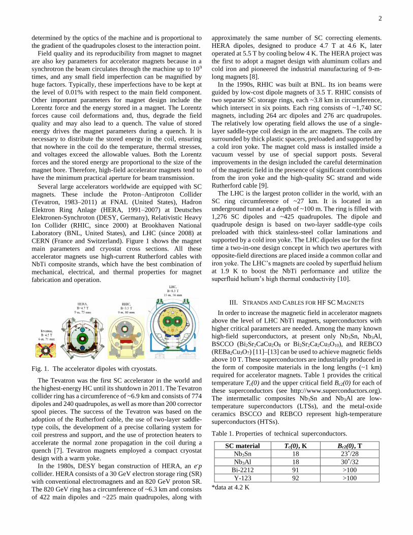
CERN (France and Switzerland). Figure 1 shows the magnet
main parameters and cryostat cross sections. All these
accelerator magnets use high-current Rutherford cables with
NbTi composite strands, which have the best combination of
mechanical, electrical, and thermal properties for magnet
fabrication and operation.
Fig. 1. The accelerator dipoles with cryostats.
The Tevatron was the first SC accelerator in the world and
the highest-energy HC until its shutdown in 2011. The Tevatron
collider ring has a circumference of ~6.9 km and consists of 774
dipoles and 240 quadrupoles, as well as more than 200 corrector
spool pieces. The success of the Tevatron was based on the
adoption of the Rutherford cable, the use of two-layer saddle-
type coils, the development of a precise collaring system for
coil prestress and support, and the use of protection heaters to
accelerate the normal zone propagation in the coil during a
quench [7]. Tevatron magnets employed a compact cryostat
design with a warm yoke.
In the 1980s, DESY began construction of HERA, an e-p
collider. HERA consists of a 30 GeV electron storage ring (SR)
with conventional electromagnets and an 820 GeV proton SR.
The 820 GeV ring has a circumference of ~6.3 km and consists
of 422 main dipoles and ~225 main quadrupoles, along with
approximately the same number of SC correcting elements.
HERA dipoles, designed to produce 4.7 T at 4.6 K, later
operated at 5.5 T by cooling below 4 K. The HERA project was
the first to adopt a magnet design with aluminum collars and
cold iron and pioneered the industrial manufacturing of 9-m-
long magnets [8].
In the 1990s, RHIC was built at BNL. Its ion beams were
guided by low-cost dipole magnets of 3.5 T. RHIC consists of
two separate SC storage rings, each ~3.8 km in circumference,
which intersect in six points. Each ring consists of ~1,740 SC
magnets, including 264 arc dipoles and 276 arc quadrupoles.
The relatively low operating field allows the use of a single-
layer saddle-type coil design in the arc magnets. The coils are
surrounded by thick plastic spacers, preloaded and supported by
a cold iron yoke. The magnet cold mass is installed inside a
vacuum vessel by use of special support posts. Several
improvements in the design included the careful determination
of the magnetic field in the presence of significant contributions
from the iron yoke and the high-quality SC strand and wide
Rutherford cable [9].
The LHC is the largest proton collider in the world, with an
SC ring circumference of ~27 km. It is located in an
underground tunnel at a depth of ~100 m. The ring is filled with
1,276 SC dipoles and ~425 quadrupoles. The dipole and
quadrupole design is based on two-layer saddle-type coils
preloaded with thick stainless-steel collar laminations and
supported by a cold iron yoke. The LHC dipoles use for the first
time a two-in-one design concept in which two apertures with
opposite-field directions are placed inside a common collar and
iron yoke. The LHC’s magnets are cooled by superfluid helium
at 1.9 K to boost the NbTi performance and utilize the
superfluid helium’s high thermal conductivity [10].
III. STRANDS AND CABLES FOR HF SC MAGNETS
In order to increase the magnetic field in accelerator magnets
above the level of LHC NbTi magnets, superconductors with
higher critical parameters are needed. Among the many known
high-field superconductors, at present only Nb3Sn, Nb3Al,
BSCCO (Bi2Sr2CaCu2O8 or Bi2Sr2Ca2Cu3O10), and REBCO
(REBa2Cu3O7) [11]–[13] can be used to achieve magnetic fields
above 10 T. These superconductors are industrially produced in
the form of composite materials in the long lengths (~1 km)
required for accelerator magnets. Table 1 provides the critical
temperature Tc(0) and the upper critical field Bc2(0) for each of
these superconductors (see http://www.superconductors.org).
The intermetallic composites Nb3Sn and Nb3Al are low-
temperature superconductors (LTSs), and the metal-oxide
ceramics BSCCO and REBCO represent high-temperature
superconductors (HTSs).
Table 1. Properties of technical superconductors.
SC material Tc(0), K Bc2(0), T
Nb3Sn 18 23*/28
Nb3Al 18 30*/32
Bi-2212 91 >100
Y-123 92 >100
*data at 4.2 K
3
A. Strands
The most promising Nb3Sn composite wires for high-field
magnets are based on the internal tin (IT) and powder-in-tube
(PIT) processes. In the IT process, niobium filaments and tin
rods are assembled in a copper matrix surrounded by a thin
niobium or tantalum diffusion barrier to prevent tin leaks into
the high-purity copper matrix. This process provides the highest
critical current density (Jc), thanks to the optimal amount of tin,
but limits the minimal subelement size achievable in the final
wire. In the PIT process, thick-walled niobium tubes are filled
with fine NbSn2 powder and stacked in a high-purity copper
matrix. This method allows an optimal combination of small
filament size (<50 µm) and Jc, comparable to those of the IT
process. However, the PIT wire cost is a factor of two to three
higher than the IT wire cost. In both methods, the Nb3Sn phase
with an optimal pinning structure is formed during a final heat
treatment at ~650–700oC for 50–100 h.
Nb3Al composite wires are made by stacking Nb-25%Al
filaments into a tantalum or niobium matrix, then extruding the
assembly down to the required size. The SC Nb3Al phase is
formed by the rapid-heating-quenching transformation (RHQT)
process, in which the Nb-Al multifilamentary wire is rapidly
heated to ~1,900°C, then quenched into a bath with liquid
gallium at ~50°C. A copper stabilizer is added via an ion- or
electroplating process. An optimal pinning structure is created
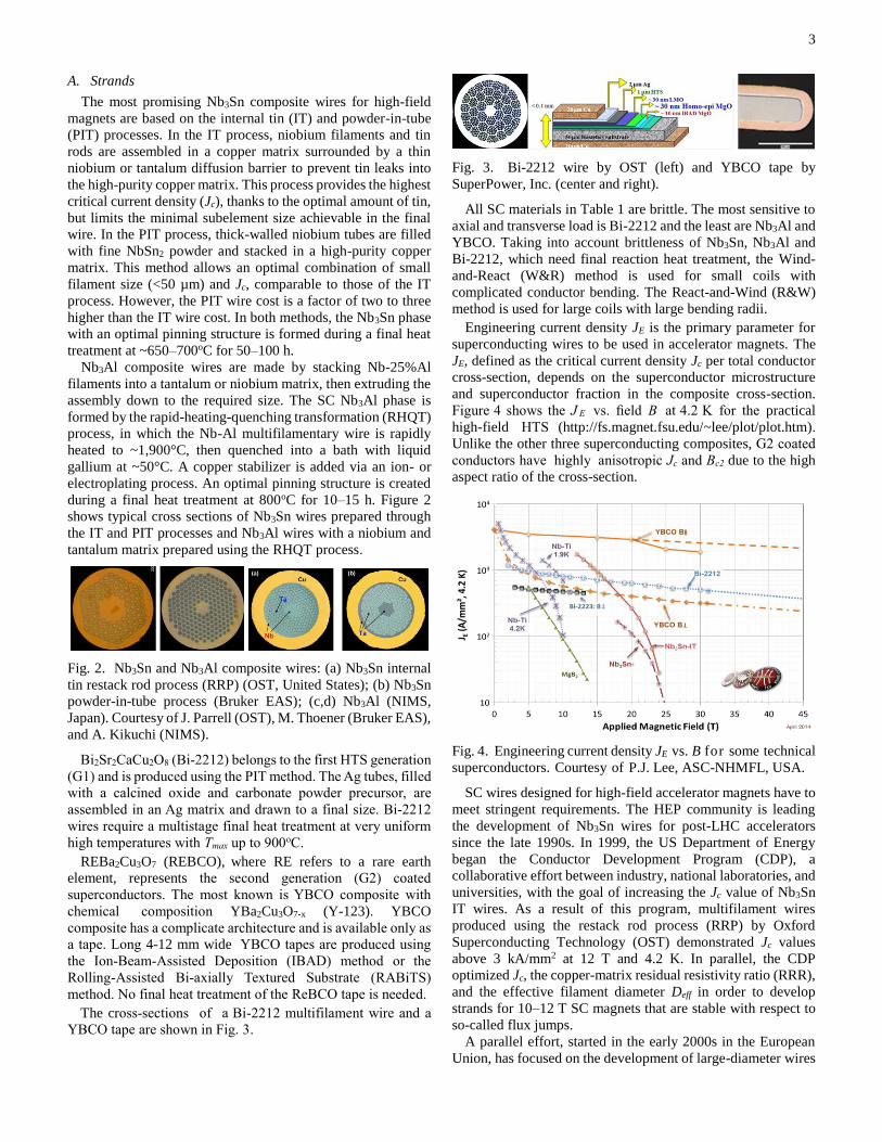
during a final heat treatment at 800oC for 10–15 h. Figure 2
shows typical cross sections of Nb3Sn wires prepared through
the IT and PIT processes and Nb3Al wires with a niobium and
tantalum matrix prepared using the RHQT process.
Fig. 2. Nb3Sn and Nb3Al composite wires: (a) Nb3Sn internal
tin restack rod process (RRP) (OST, United States); (b) Nb3Sn
powder-in-tube process (Bruker EAS); (c,d) Nb3Al (NIMS,
Japan). Courtesy of J. Parrell (OST), M. Thoener (Bruker EAS),
and A. Kikuchi (NIMS).
Bi2Sr2CaCu2O8 (Bi-2212) belongs to the first HTS generation
(G1) and is produced using the PIT method. The Ag tubes, filled
with a calcined oxide and carbonate powder precursor, are
assembled in an Ag matrix and drawn to a final size. Bi-2212
wires require a multistage final heat treatment at very uniform
high temperatures with Tmax up to 900oC.
REBa2Cu3O7 (REBCO), where RE refers to a rare earth
element, represents the second generation (G2) coated
superconductors. The most known is YBCO composite with
chemical composition YBa2Cu3O7-x (Y-123). YBCO
composite has a complicate architecture and is available only as
a tape. Long 4-12 mm wide YBCO tapes are produced using
the Ion-Beam-Assisted Deposition (IBAD) method or the
Rolling-Assisted Bi-axially Textured Substrate (RABiTS)
method. No final heat treatment of the ReBCO tape is needed.
The cross-sections of a Bi-2212 multifilament wire and a
YBCO tape are shown in Fig. 3.
Fig. 3. Bi-2212 wire by OST (left) and YBCO tape by
SuperPower, Inc. (center and right).
All SC materials in Table 1 are brittle. The most sensitive to
axial and transverse load is Bi-2212 and the least are Nb3Al and
YBCO. Taking into account brittleness of Nb3Sn, Nb3Al and
Bi-2212, which need final reaction heat treatment, the Wind-
and-React (W&R) method is used for small coils with
complicated conductor bending. The React-and-Wind (R&W)
method is used for large coils with large bending radii.
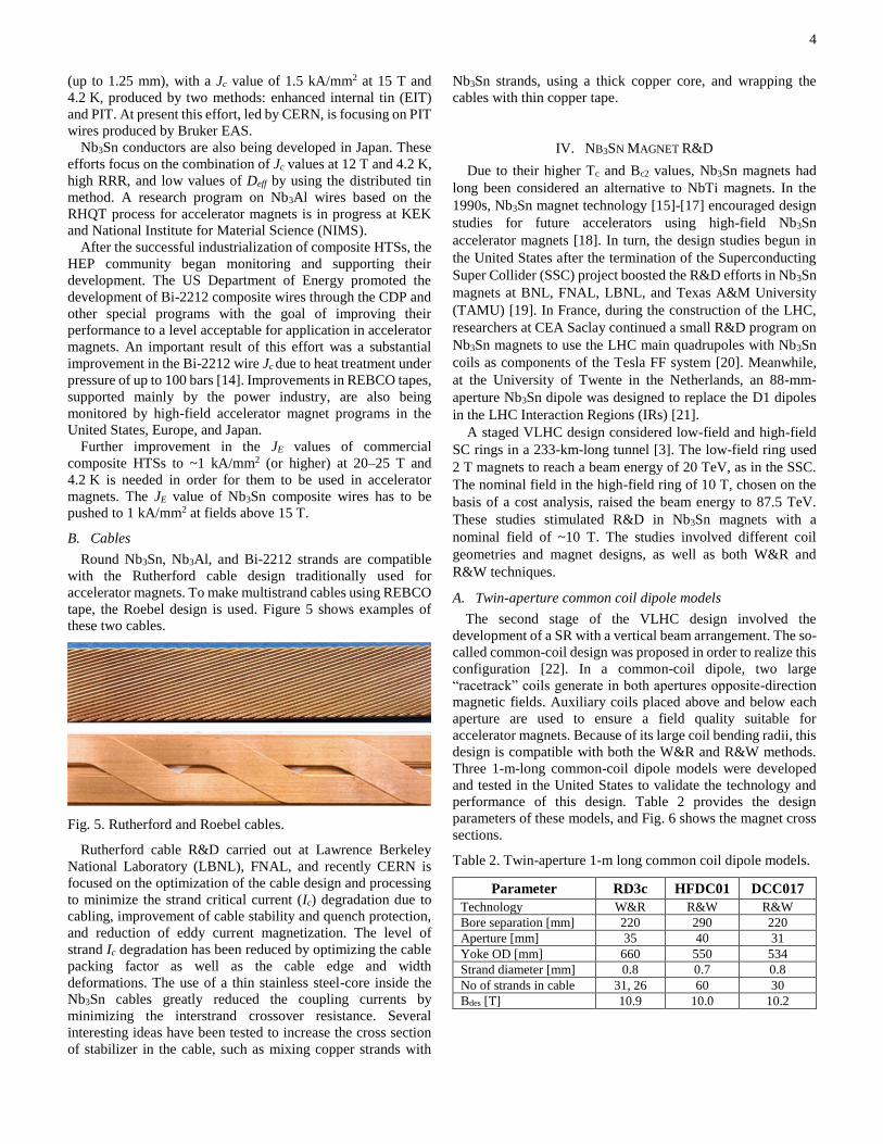
Engineering current density JE is the primary parameter for
superconducting wires to be used in accelerator magnets. The
JE, defined as the critical current density Jc per total conductor
cross-section, depends on the superconductor microstructure
and superconductor fraction in the composite cross-section.
Figure 4 shows the J E vs. field B at 4.2 K for the practical
high-field HTS (http://fs.magnet.fsu.edu/~lee/plot/plot.htm).
Unlike the other three superconducting composites, G2 coated
conductors have highly anisotropic Jc and Bc2 due to the high
aspect ratio of the cross-section.
Fig. 4. Engineering current density JE vs. B for some technical
superconductors. Courtesy of P.J. Lee, ASC-NHMFL, USA.
SC wires designed for high-field accelerator magnets have to
meet stringent requirements. The HEP community is leading
the development of Nb3Sn wires for post-LHC accelerators
since the late 1990s. In 1999, the US Department of Energy
began the Conductor Development Program (CDP), a
collaborative effort between industry, national laboratories, and
universities, with the goal of increasing the Jc value of Nb3Sn
IT wires. As a result of this program, multifilament wires
produced using the restack rod process (RRP) by Oxford
Superconducting Technology (OST) demonstrated Jc values
above 3 kA/mm2 at 12 T and 4.2 K. In parallel, the CDP
optimized Jc, the copper-matrix residual resistivity ratio (RRR),
and the effective filament diameter Deff in order to develop
strands for 10–12 T SC magnets that are stable with respect to
so-called flux jumps.
A parallel effort, started in the early 2000s in the European
Union, has focused on the development of large-diameter wires
4
(up to 1.25 mm), with a Jc value of 1.5 kA/mm2 at 15 T and
4.2 K, produced by two methods: enhanced internal tin (EIT)
and PIT. At present this effort, led by CERN, is focusing on PIT
wires produced by Bruker EAS.
Nb3Sn conductors are also being developed in Japan. These
efforts focus on the combination of Jc values at 12 T and 4.2 K,
high RRR, and low values of Deff by using the distributed tin
method. A research program on Nb3Al wires based on the
RHQT process for accelerator magnets is in progress at KEK
and National Institute for Material Science (NIMS).
After the successful industrialization of composite HTSs, the
HEP community began monitoring and supporting their
development. The US Department of Energy promoted the
development of Bi-2212 composite wires through the CDP and
other special programs with the goal of improving their
performance to a level acceptable for application in accelerator
magnets. An important result of this effort was a substantial
improvement in the Bi-2212 wire Jc due to heat treatment under
pressure of up to 100 bars [14]. Improvements in REBCO tapes,
supported mainly by the power industry, are also being
monitored by high-field accelerator magnet programs in the
United States, Europe, and Japan.
Further improvement in the JE values of commercial
composite HTSs to ~1 kA/mm2 (or higher) at 20–25 T and
4.2 K is needed in order for them to be used in accelerator
magnets. The JE value of Nb3Sn composite wires has to be
pushed to 1 kA/mm2 at fields above 15 T.
B. Cables
Round Nb3Sn, Nb3Al, and Bi-2212 strands are compatible
with the Rutherford cable design traditionally used for
accelerator magnets. To make multistrand cables using REBCO
tape, the Roebel design is used. Figure 5 shows examples of
these two cables.
Fig. 5. Rutherford and Roebel cables.
Rutherford cable R&D carried out at Lawrence Berkeley
National Laboratory (LBNL), FNAL, and recently CERN is
focused on the optimization of the cable design and processing
to minimize the strand critical current (Ic) degradation due to
cabling, improvement of cable stability and quench protection,
and reduction of eddy current magnetization. The level of
strand Ic degradation has been reduced by optimizing the cable
packing factor as well as the cable edge and width
deformations. The use of a thin stainless steel-core inside the
Nb3Sn cables greatly reduced the coupling currents by
minimizing the interstrand crossover resistance. Several
interesting ideas have been tested to increase the cross section
of stabilizer in the cable, such as mixing copper strands with
Nb3Sn strands, using a thick copper core, and wrapping the
cables with thin copper tape.
IV. NB3SN MAGNET R&D
Due to their higher Tc and Bc2 values, Nb3Sn magnets had
long been considered an alternative to NbTi magnets. In the
1990s, Nb3Sn magnet technology [15]-[17] encouraged design
studies for future accelerators using high-field Nb3Sn
accelerator magnets [18]. In turn, the design studies begun in
the United States after the termination of the Superconducting
Super Collider (SSC) project boosted the R&D efforts in Nb3Sn
magnets at BNL, FNAL, LBNL, and Texas A&M University
(TAMU) [19]. In France, during the construction of the LHC,
researchers at CEA Saclay continued a small R&D program on
Nb3Sn magnets to use the LHC main quadrupoles with Nb3Sn
coils as components of the Tesla FF system [20]. Meanwhile,
at the University of Twente in the Netherlands, an 88-mm-
aperture Nb3Sn dipole was designed to replace the D1 dipoles
in the LHC Interaction Regions (IRs) [21].
A staged VLHC design considered low-field and high-field
SC rings in a 233-km-long tunnel [3]. The low-field ring used
2 T magnets to reach a beam energy of 20 TeV, as in the SSC.
The nominal field in the high-field ring of 10 T, chosen on the
basis of a cost analysis, raised the beam energy to 87.5 TeV.
These studies stimulated R&D in Nb3Sn magnets with a
nominal field of ~10 T. The studies involved different coil
geometries and magnet designs, as well as both W&R and
R&W techniques.
A. Twin-aperture common coil dipole models
The second stage of the VLHC design involved the
development of a SR with a vertical beam arrangement. The so-
called common-coil design was proposed in order to realize this
configuration [22]. In a common-coil dipole, two large
“racetrack” coils generate in both apertures opposite-direction
magnetic fields. Auxiliary coils placed above and below each
aperture are used to ensure a field quality suitable for
accelerator magnets. Because of its large coil bending radii, this
design is compatible with both the W&R and R&W methods.
Three 1-m-long common-coil dipole models were developed
and tested in the United States to validate the technology and
performance of this design. Table 2 provides the design
parameters of these models, and Fig. 6 shows the magnet cross
sections.
Table 2. Twin-aperture 1-m long common coil dipole models.
Parameter RD3c HFDC01 DCC017
Technology W&R R&W R&W
Bore separation [mm] 220 290 220
Aperture [mm] 35 40 31
Yoke OD [mm] 660 550 534
Strand diameter [mm] 0.8 0.7 0.8
No of strands in cable 31, 26 60 30
Bdes [T] 10.9 10.0 10.2
5
Fig. 6. Twin-aperture common-coil dipole models. (a) RD3c
(LBNL), (b) DCC017 (BNL), and (c) HFDC01 (FNAL). Courtesy of R. Hafalia (LBNL), R. Gupta (BNL), and V.V.
Kashikhin (FNAL).
A magnet model known as RD3c was developed at LBNL as
an inexpensive test of an accelerator-quality common-coil
dipole based on the W&R method [23]. The magnet consists of
two flat, two-layer racetrack coils on both sides of two apertures
and auxiliary coils between the apertures. Prior to their use in
RD3c, the outer coils were tested in a simpler configuration,
RD3b, without an aperture; they reached the maximum field in
the coil of 14.5 T at 4.3 K [24]. The maximum bore field
obtained in RD3c after 15 training quenches was 10.03 T at
4.3 K. The measured field harmonics correlated with results
from calculations.
A more complicated accelerator-quality common-coil dipole
model, HFDC01, was developed and tested at FNAL [25]. This
magnet, designed to generate a 10 T field in two 40-mm
apertures at 4.5 K, was based on high-performance Nb3Sn
strands and use of the R&W technique. It consists of single-
layer coils, a 22-mm-wide 60-strand Rutherford cable, and a
stainless-steel collar. Both the left and right coils were wound
simultaneously into the collar structure and then filled with
epoxy. The R&W method was optimized with a series of simple
two-layer racetrack models without an aperture [26]. After a
long training period, HFDC01 reached a bore field of only ~6 T
and was limited by flux jumps in the superconductor. Results
from magnetic measurements confirmed that the good field
quality agreed with the magnetic design.
The Nb3Sn common-coil dipole model DCC017 was made at
BNL, also using the R&W technique [27]. This magnet consists
of two two-layer flat racetrack coils separated by a clear
horizontal space of 31 mm. The mechanical structure includes
a stainless-steel collar, a cold yoke, and a stainless-steel skin.
The coil ends are supported by thick stainless-steel end plates.
After a long training, this magnet reached the expected short
sample field of 10.2 T at 4.5 K.
The models described above validated the feasibility and
revealed the complexity of the common-coil design. It was
recognized that more research is needed to further explore the
potential of this design and R&W technology for accelerator
magnets, including optimization of the conductor, its structure,
and the fabrication process.
B. Single-aperture dipole models
Single-aperture models were used to achieve the highest
possible accelerator quality and performance reproducibility of
the Nb3Sn accelerator magnets. R&D efforts at LBNL aimed to
demonstrate the Nb3Sn dipole field limit by using block-type
coils [28]. R&D efforts at FNAL focused on demonstrating
accelerator-quality magnets based on traditional cosθ coils [29].
At the same time, the magnet group at TAMU proposed [30]
and studied [31] a concept of stress management in high-field
dipoles based on block-type coils. Table 3 lists the design
parameters of the single-aperture dipole magnets developed and
tested at LBNL and FNAL, and Fig. 7 shows the magnet cross
sections.
Fig. 7. Single-aperture Nb3Sn dipole models: (a) HD2/3
(LBNL), (b) HFDA (FNAL). Courtesy of S. Caspi (LBNL) and
V.V. Kashikhin (FNAL).
Table 3. Single-aperture 1-m long dipole models
Parameter HD2 HFDA
Coil design Block Cos-theta
Aperture [mm] 36 43.5
Yoke OD [mm] 625 400
Strand diameter [mm] 0.8 1.0
No of strands in cable 51 27 or 28
Bmax [T] 15.4 12.2
The first model in the HD series of magnets created at LBNL,
HD1, used a flat racetrack coil configuration with only a 10-
mm bore [32]. A special support structure based on a thick
aluminum shell and a technique involving keys and water-
pressurized bladders were used in its construction [33]. HD1
reached a bore field as high as 16 T [34], demonstrating the
potential of Nb3Sn block coils and the coil support structure.
The HD2 and HD3 dipole models of this series were designed
to achieve a field above 15 T at 4.3 K and normalized field
harmonics below one unit (10-4) in a clear bore of 36 mm [35].
The HD2/3 cross section consists of two two-layer coil
modules. A stainless-steel pipe, placed between the top and
bottom coils, forms the magnet aperture. To accommodate the
pipe in magnet ends, the ends of two midplane racetrack coils
are flared. Similar to HD1, the HD2/3 mechanical structure uses
a thick aluminum shell and the key-and-bladder preloading
technique. The HD2 design peak field in coils is ~16 T. The
low-order geometrical field harmonics in aperture are less than
0.1 units at the reference radius Rref of 10 mm. The yoke cross
section was optimized to reduce the saturation effects.
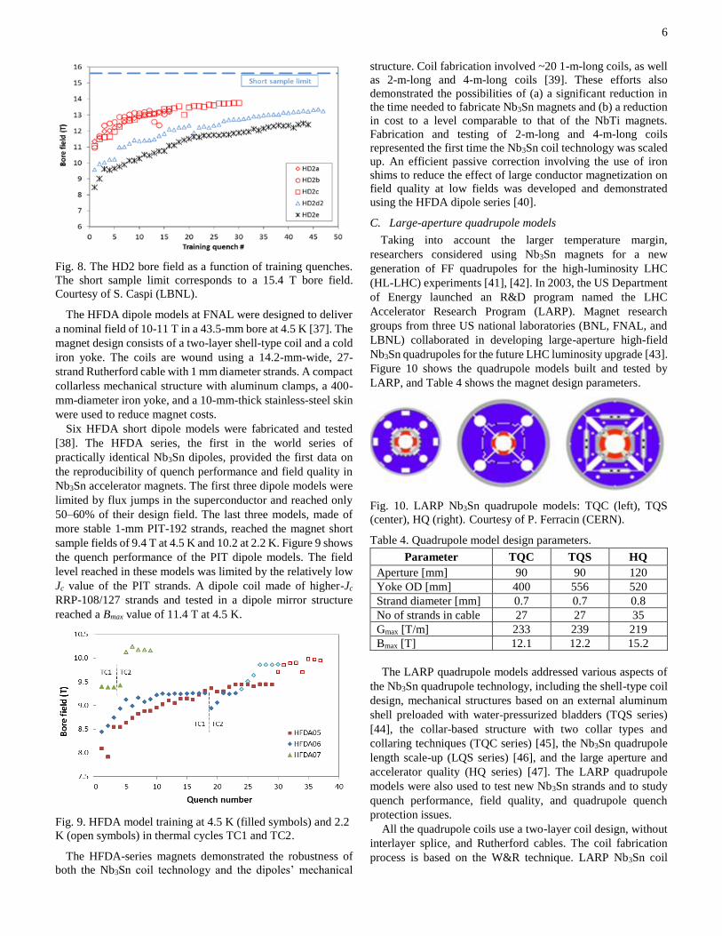
Figure 8 shows the bore field versus training quench number
for five HD2 model tests at 4.3 K. The HD2c model reached its
maximum field in the aperture of 13.8 T (the record dipole field
at present!), or 85% of magnet design field [36]. Attempts to
improve the conductor insulation and the coil end design in the
HD3 model did not improve the magnet performance.
6
Fig. 8. The HD2 bore field as a function of training quenches.
The short sample limit corresponds to a 15.4 T bore field.
Courtesy of S. Caspi (LBNL).
The HFDA dipole models at FNAL were designed to deliver
a nominal field of 10-11 T in a 43.5-mm bore at 4.5 K [37]. The
magnet design consists of a two-layer shell-type coil and a cold
iron yoke. The coils are wound using a 14.2-mm-wide, 27-
strand Rutherford cable with 1 mm diameter strands. A compact
collarless mechanical structure with aluminum clamps, a 400-
mm-diameter iron yoke, and a 10-mm-thick stainless-steel skin
were used to reduce magnet costs.
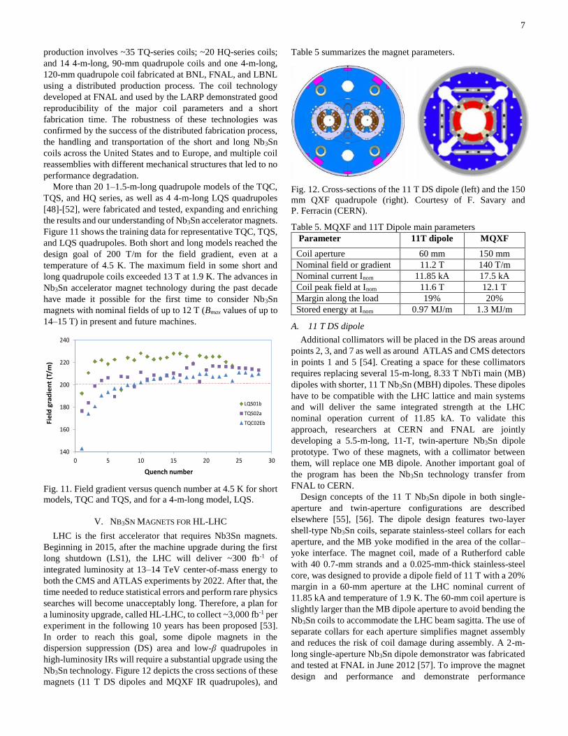
Six HFDA short dipole models were fabricated and tested
[38]. The HFDA series, the first in the world series of
practically identical Nb3Sn dipoles, provided the first data on
the reproducibility of quench performance and field quality in
Nb3Sn accelerator magnets. The first three dipole models were
limited by flux jumps in the superconductor and reached only
50–60% of their design field. The last three models, made of
more stable 1-mm PIT-192 strands, reached the magnet short
sample fields of 9.4 T at 4.5 K and 10.2 at 2.2 K. Figure 9 shows
the quench performance of the PIT dipole models. The field
level reached in these models was limited by the relatively low
Jc value of the PIT strands. A dipole coil made of higher-Jc
RRP-108/127 strands and tested in a dipole mirror structure
reached a Bmax value of 11.4 T at 4.5 K.
Fig. 9. HFDA model training at 4.5 K (filled symbols) and 2.2
K (open symbols) in thermal cycles TC1 and TC2.
The HFDA-series magnets demonstrated the robustness of
both the Nb3Sn coil technology and the dipoles’ mechanical
structure. Coil fabrication involved ~20 1-m-long coils, as well
as 2-m-long and 4-m-long coils [39]. These efforts also
demonstrated the possibilities of (a) a significant reduction in
the time needed to fabricate Nb3Sn magnets and (b) a reduction
in cost to a level comparable to that of the NbTi magnets.
Fabrication and testing of 2-m-long and 4-m-long coils
represented the first time the Nb3Sn coil technology was scaled
up. An efficient passive correction involving the use of iron
shims to reduce the effect of large conductor magnetization on
field quality at low fields was developed and demonstrated
using the HFDA dipole series [40].
C. Large-aperture quadrupole models
Taking into account the larger temperature margin,
researchers considered using Nb3Sn magnets for a new
generation of FF quadrupoles for the high-luminosity LHC
(HL-LHC) experiments [41], [42]. In 2003, the US Department
of Energy launched an R&D program named the LHC
Accelerator Research Program (LARP). Magnet research
groups from three US national laboratories (BNL, FNAL, and
LBNL) collaborated in developing large-aperture high-field
Nb3Sn quadrupoles for the future LHC luminosity upgrade [43].
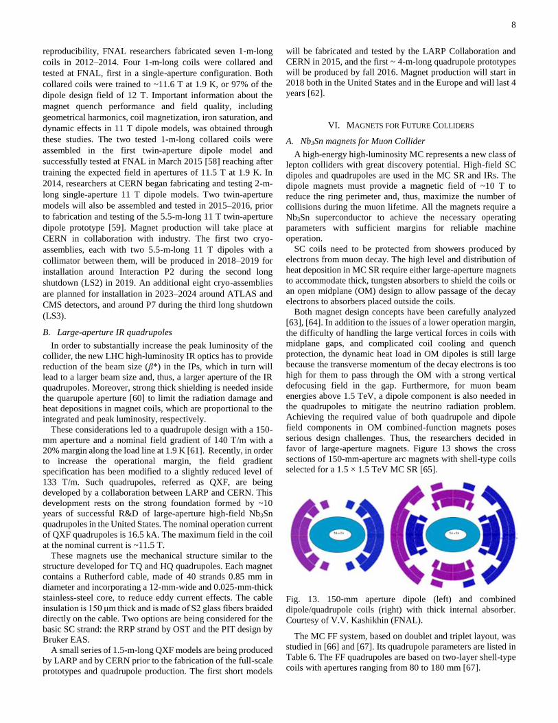
Figure 10 shows the quadrupole models built and tested by
LARP, and Table 4 shows the magnet design parameters.
Fig. 10. LARP Nb3Sn quadrupole models: TQC (left), TQS
(center), HQ (right). Courtesy of P. Ferracin (CERN).
Table 4. Quadrupole model design parameters.
Parameter TQC TQS HQ
Aperture [mm] 90 90 120
Yoke OD [mm] 400 556 520
Strand diameter [mm] 0.7 0.7 0.8
No of strands in cable 27 27 35
Gmax [T/m] 233 239 219
Bmax [T] 12.1 12.2 15.2
The LARP quadrupole models addressed various aspects of
the Nb3Sn quadrupole technology, including the shell-type coil
design, mechanical structures based on an external aluminum
shell preloaded with water-pressurized bladders (TQS series)
[44], the collar-based structure with two collar types and
collaring techniques (TQC series) [45], the Nb3Sn quadrupole
length scale-up (LQS series) [46], and the large aperture and
accelerator quality (HQ series) [47]. The LARP quadrupole
models were also used to test new Nb3Sn strands and to study
quench performance, field quality, and quadrupole quench
protection issues.
All the quadrupole coils use a two-layer coil design, without
interlayer splice, and Rutherford cables. The coil fabrication
process is based on the W&R technique. LARP Nb3Sn coil
7
production involves ~35 TQ-series coils; ~20 HQ-series coils;
and 14 4-m-long, 90-mm quadrupole coils and one 4-m-long,
120-mm quadrupole coil fabricated at BNL, FNAL, and LBNL
using a distributed production process. The coil technology
developed at FNAL and used by the LARP demonstrated good
reproducibility of the major coil parameters and a short
fabrication time. The robustness of these technologies was
confirmed by the success of the distributed fabrication process,
the handling and transportation of the short and long Nb3Sn
coils across the United States and to Europe, and multiple coil
reassemblies with different mechanical structures that led to no
performance degradation.
More than 20 1–1.5-m-long quadrupole models of the TQC,
TQS, and HQ series, as well as 4 4-m-long LQS quadrupoles
[48]-[52], were fabricated and tested, expanding and enriching
the results and our understanding of Nb3Sn accelerator magnets.
Figure 11 shows the training data for representative TQC, TQS,
and LQS quadrupoles. Both short and long models reached the
design goal of 200 T/m for the field gradient, even at a
temperature of 4.5 K. The maximum field in some short and
long quadrupole coils exceeded 13 T at 1.9 K. The advances in
Nb3Sn accelerator magnet technology during the past decade
have made it possible for the first time to consider Nb3Sn
magnets with nominal fields of up to 12 T (Bmax values of up to
14–15 T) in present and future machines.
Fig. 11. Field gradient versus quench number at 4.5 K for short
models, TQC and TQS, and for a 4-m-long model, LQS.
V. NB3SN MAGNETS FOR HL-LHC
LHC is the first accelerator that requires Nb3Sn magnets.
Beginning in 2015, after the machine upgrade during the first
long shutdown (LS1), the LHC will deliver ~300 fb-1 of
integrated luminosity at 13–14 TeV center-of-mass energy to
both the CMS and ATLAS experiments by 2022. After that, the
time needed to reduce statistical errors and perform rare physics
searches will become unacceptably long. Therefore, a plan for
a luminosity upgrade, called HL-LHC, to collect ~3,000 fb-1 per
experiment in the following 10 years has been proposed [53].
In order to reach this goal, some dipole magnets in the
dispersion suppression (DS) area and low-β quadrupoles in
high-luminosity IRs will require a substantial upgrade using the
Nb3Sn technology. Figure 12 depicts the cross sections of these
magnets (11 T DS dipoles and MQXF IR quadrupoles), and
Table 5 summarizes the magnet parameters.
Fig. 12. Cross-sections of the 11 T DS dipole (left) and the 150
mm QXF quadrupole (right). Courtesy of F. Savary and
P. Ferracin (CERN).
Table 5. MQXF and 11T Dipole main parameters
Parameter 11T dipole MQXF
Coil aperture 60 mm 150 mm
Nominal field or gradient 11.2 T 140 T/m
Nominal current Inom 11.85 kA 17.5 kA
Coil peak field at Inom 11.6 T 12.1 T
Margin along the load 19% 20%
Stored energy at Inom 0.97 MJ/m 1.3 MJ/m
A. 11 T DS dipole
Additional collimators will be placed in the DS areas around
points 2, 3, and 7 as well as around ATLAS and CMS detectors
in points 1 and 5 [54]. Creating a space for these collimators
requires replacing several 15-m-long, 8.33 T NbTi main (MB)
dipoles with shorter, 11 T Nb3Sn (MBH) dipoles. These dipoles
have to be compatible with the LHC lattice and main systems
and will deliver the same integrated strength at the LHC
nominal operation current of 11.85 kA. To validate this
approach, researchers at CERN and FNAL are jointly
developing a 5.5-m-long, 11-T, twin-aperture Nb3Sn dipole
prototype. Two of these magnets, with a collimator between
them, will replace one MB dipole. Another important goal of
the program has been the Nb3Sn technology transfer from
FNAL to CERN.
Design concepts of the 11 T Nb3Sn dipole in both single-
aperture and twin-aperture configurations are described
elsewhere [55], [56]. The dipole design features two-layer
shell-type Nb3Sn coils, separate stainless-steel collars for each
aperture, and the MB yoke modified in the area of the collar–
yoke interface. The magnet coil, made of a Rutherford cable
with 40 0.7-mm strands and a 0.025-mm-thick stainless-steel
core, was designed to provide a dipole field of 11 T with a 20%
margin in a 60-mm aperture at the LHC nominal current of
11.85 kA and temperature of 1.9 K. The 60-mm coil aperture is
slightly larger than the MB dipole aperture to avoid bending the
Nb3Sn coils to accommodate the LHC beam sagitta. The use of
separate collars for each aperture simplifies magnet assembly
and reduces the risk of coil damage during assembly. A 2-m-
long single-aperture Nb3Sn dipole demonstrator was fabricated
and tested at FNAL in June 2012 [57]. To improve the magnet
design and performance and demonstrate performance
140
160
180
200
220
240
0 5 10 15 20 25 30
Fie
ld g
rad
ien
t (T
/m)
Quench number
LQS01b
TQS02a
TQC02Eb
8
reproducibility, FNAL researchers fabricated seven 1-m-long
coils in 2012–2014. Four 1-m-long coils were collared and
tested at FNAL, first in a single-aperture configuration. Both
collared coils were trained to ~11.6 T at 1.9 K, or 97% of the
dipole design field of 12 T. Important information about the
magnet quench performance and field quality, including
geometrical harmonics, coil magnetization, iron saturation, and
dynamic effects in 11 T dipole models, was obtained through
these studies. The two tested 1-m-long collared coils were
assembled in the first twin-aperture dipole model and
successfully tested at FNAL in March 2015 [58] reaching after
training the expected field in apertures of 11.5 T at 1.9 K. In
2014, researchers at CERN began fabricating and testing 2-m-
long single-aperture 11 T dipole models. Two twin-aperture
models will also be assembled and tested in 2015–2016, prior
to fabrication and testing of the 5.5-m-long 11 T twin-aperture
dipole prototype [59]. Magnet production will take place at
CERN in collaboration with industry. The first two cryo-
assemblies, each with two 5.5-m-long 11 T dipoles with a
collimator between them, will be produced in 2018–2019 for
installation around Interaction P2 during the second long
shutdown (LS2) in 2019. An additional eight cryo-assemblies
are planned for installation in 2023–2024 around ATLAS and
CMS detectors, and around P7 during the third long shutdown
(LS3).
B. Large-aperture IR quadrupoles
In order to substantially increase the peak luminosity of the
collider, the new LHC high-luminosity IR optics has to provide
reduction of the beam size (β*) in the IPs, which in turn will
lead to a larger beam size and, thus, a larger aperture of the IR
quadrupoles. Moreover, strong thick shielding is needed inside
the quarupole aperture [60] to limit the radiation damage and
heat depositions in magnet coils, which are proportional to the
integrated and peak luminosity, respectively.
These considerations led to a quadrupole design with a 150-
mm aperture and a nominal field gradient of 140 T/m with a
20% margin along the load line at 1.9 K [61]. Recently, in order
to increase the operational margin, the field gradient
specification has been modified to a slightly reduced level of
133 T/m. Such quadrupoles, referred as QXF, are being
developed by a collaboration between LARP and CERN. This
development rests on the strong foundation formed by ~10
years of successful R&D of large-aperture high-field Nb3Sn
quadrupoles in the United States. The nominal operation current
of QXF quadrupoles is 16.5 kA. The maximum field in the coil
at the nominal current is ~11.5 T.
These magnets use the mechanical structure similar to the
structure developed for TQ and HQ quadrupoles. Each magnet
contains a Rutherford cable, made of 40 strands 0.85 mm in
diameter and incorporating a 12-mm-wide and 0.025-mm-thick
stainless-steel core, to reduce eddy current effects. The cable
insulation is 150 μm thick and is made of S2 glass fibers braided
directly on the cable. Two options are being considered for the
basic SC strand: the RRP strand by OST and the PIT design by
Bruker EAS.
A small series of 1.5-m-long QXF models are being produced
by LARP and by CERN prior to the fabrication of the full-scale
prototypes and quadrupole production. The first short models
will be fabricated and tested by the LARP Collaboration and
CERN in 2015, and the first ~ 4-m-long quadrupole prototypes
will be produced by fall 2016. Magnet production will start in
2018 both in the United States and in the Europe and will last 4
years [62].
VI. MAGNETS FOR FUTURE COLLIDERS
A. Nb3Sn magnets for Muon Collider
A high-energy high-luminosity MC represents a new class of
lepton colliders with great discovery potential. High-field SC
dipoles and quadrupoles are used in the MC SR and IRs. The
dipole magnets must provide a magnetic field of ~10 T to
reduce the ring perimeter and, thus, maximize the number of
collisions during the muon lifetime. All the magnets require a
Nb3Sn superconductor to achieve the necessary operating
parameters with sufficient margins for reliable machine
operation.
SC coils need to be protected from showers produced by
electrons from muon decay. The high level and distribution of
heat deposition in MC SR require either large-aperture magnets
to accommodate thick, tungsten absorbers to shield the coils or
an open midplane (OM) design to allow passage of the decay
electrons to absorbers placed outside the coils.
Both magnet design concepts have been carefully analyzed
[63], [64]. In addition to the issues of a lower operation margin,
the difficulty of handling the large vertical forces in coils with
midplane gaps, and complicated coil cooling and quench
protection, the dynamic heat load in OM dipoles is still large
because the transverse momentum of the decay electrons is too
high for them to pass through the OM with a strong vertical
defocusing field in the gap. Furthermore, for muon beam
energies above 1.5 TeV, a dipole component is also needed in
the quadrupoles to mitigate the neutrino radiation problem.
Achieving the required value of both quadrupole and dipole
field components in OM combined-function magnets poses
serious design challenges. Thus, the researchers decided in
favor of large-aperture magnets. Figure 13 shows the cross
sections of 150-mm-aperture arc magnets with shell-type coils
selected for a 1.5 × 1.5 TeV MC SR [65].
Fig. 13. 150-mm aperture dipole (left) and combined
dipole/quadrupole coils (right) with thick internal absorber. Courtesy of V.V. Kashikhin (FNAL).
The MC FF system, based on doublet and triplet layout, was
studied in [66] and [67]. Its quadrupole parameters are listed in
Table 6. The FF quadrupoles are based on two-layer shell-type
coils with apertures ranging from 80 to 180 mm [67].
9
Table 6. IR Quadrupole Parameters at 4.5 K.
Parameter Q1 Q2 Q3 Q4-6 Q7 Q8-9
Aperture (mm) 80 100 125 140 160 180
Bmax coil (T) 14.1 14.3 14.5 14.7 14.8 15.2
Gmax (T/m) 308 249 202 182 161 127
Gop (T/m) 250 200 161 144 125 90
Margin Gop/Gmax 0.81 0.80 0.80 0.79 0.78 0.71
E at Gop (MJ/m) 0.7 0.8 1.1 1.2 1.4 1.1
Neutrino radiation is an important factor for a TeV-scale MC.
In the quadrupoles nearest to the IP, the natural beam
divergence is sufficient to spread this radiation, but in more
distant quadrupoles, an additional bending field of ~2 T is
necessary. This bending field is created by special dipole coils
in quadrupoles Q8 and Q9.
The MC quadrupole parameters are close to those of the
LARP quadrupoles described above. However, for MC IR
operation at 4.5 K with a proper margin, these magnets require
an increase in coil thickness. Focused R&D will be needed for
larger-aperture quadrupoles (inner diameter ~180–200 mm)
with dipole windings as well as for challenging large-aperture
SR dipoles and quadrupoles.
B. Nb3Sn magnets for Hadron Collider
HCs are considered the most powerful discovery tools in
HEP. An interest in an HC with energy beyond the LHC’s reach
gained additional momentum in the context of recent strategic
plans developed in the United States, European Union, and
China. To build an ~100 TeV HC in an ~100 km tunnel, ~15 T
dipoles operating at 1.9 or 4.5 K with a 15–20% operation
margin are needed. The required nominal field of ~15 T enables
use of the Nb3Sn technology. The main challenges for this
category of Nb3Sn magnet include substantially higher
electromagnetic forces and higher storage energy. A substantial
reduction in the cost of producing the magnets will be key for
the practical realization of such a machine. The development
and demonstration of cost-effective 15-16 T Nb3Sn accelerator
dipoles have started in the United States, European Union, and
Asia and are planned to take place over the next 5–10 years.
The European EuCARD program is exploring the block-type
dipole design. At present it is developing 100-mm-aperture
Nb3Sn dipole magnet called FRESCA2 to upgrade the cable test
facility at CERN [68]. With a target bore field of 13 T, this
magnet is designed for a maximum bore field of 16.0 at 4.2 K
or 17.2 T at 1.9 K. It incorporates the design concept of LBNL’s
HD models and consists of four 1.5-m-long double-layer coils
wound with a 21-mm-wide cable. The coils are supported by a
structure based on a 65-mm-thick aluminum shell and installed
using the key-and-bladder preloading technique. The coils of
FRESCA2 are wound with a Rutherford cable composed of 40
strands 1 mm in diameter. Fabrication is in progress, and a test
is planned for 2016.
FNAL is developing a 15 T Nb3Sn dipole demonstrator by
using four-layer shell-type coils. First, the existing 11 T dipole
developed for the LHC upgrade [55] will be modified by adding
another two layers to achieve a 15 T field in a 60-mm aperture.
Then, the subsequent model will use an optimized four-layer
graded coil. The magnet and tooling design is in progress, and
a test of the first model is planned for 2016.
LBNL is working on the canted cosine theta (CCT) dipole
design to achieve a significant reduction in conductor stress
[69]. Figure 14 shows the tilted solenoid windings, each
supported by a channel. Several tests, each with larger number
of coil layers and higher fields, are planned for 2015–2016. The
tests will begin with 2 layers that yield a 10 T field in a 90-mm
bore; later, 6 extra layers will gradually raise the field to 16 T.
Fig. 14. A canted cosθ dipole coil. Courtesy of S. Caspi
(LBNL).
A high-field accelerator magnet R&D program has recently
been launched in China (https://indico.cern.ch/event/328599/
session/4/contribution/20/material/slides/1.pdf). During 2015–
2020, the program will develop a twin-aperture Nb3Sn dipole
based on the common-coil configuration with a nominal
operation field of 12 T and accelerator field quality. In 2020–
2025, the program will develop a 15 T, twin-aperture,
accelerator-quality Nb3Sn dipole and quadrupole.
In Japan, KEK has been developing a subscale magnet [70]
to demonstrate the feasibility of Nb3Al cables, carrying out
R&D on relevant magnet technologies such as insulation, and
performing a radiation resistance study.
C. HTS magnets
The Nb3Sn magnet technology is ultimately limited by the Bc2
values of Nb3Sn superconductors (~27 T) and the conductors’
ability to transport current at high fields. For Nb3Sn dipoles, the
ultimate nominal field is limited by 15–16 T. A breakthrough
in high-field pinning in Nb3Sn may result in an increase of the
achievable field to perhaps 20 T [71]. However, to surpass these
fields, the magnets need HTS materials which have much
higher Bc2 values.
Fig. 15. Hybrid coil with high- and low-temperature
superconductors. Courtesy of E. Todesco (CERN).
Fig. 16. High-temperature superconductor inserts inside low-
temperature superconductor background magnet based on (a)
block and (b) cosθ coils. Courtesy of G. de Rijk (CERN) and
C. Lorin (CEA Saclay).
10
Figures 15 and 16 depict the two main approaches to the HTS
accelerator magnets presently under consideration. The first
approach uses hybrid coils made of HTSs and LTSs [72]. The
second approach uses HTS inserts placed inside LTS magnets
[73], [74]. In both cases, superconductor grading is used to
reduce magnet cost and make the best use of the materials’
properties. To save volume and cost, the LTS part of the coil is
further divided into Nb3Sn and NbTi subsections.
The HTS/LTS coil shown in Fig. 15 uses the block design
chosen on the basis of a simpler separation between the HTS
and LTS regions as well as stress considerations. This coil
design relies on flared ends, which require conductor bending
in the “hard” direction; thus, the design needs experimental
validation, especially for HTS tapes.
The HTS inserts shown in Fig. 16 are based on both block
(Fig. 16a) and shell-type (Fig. 16b) coils. HTS inserts based on
CCT design are also being developed [75]. The inserts need
their own mechanical structure, which should be compatible
with the HTS coil design and technology and with the outsert
magnet.
The use of HTS coils poses serious challenges for accelerator
magnets due to the specific properties of HTSs and the use of
HTS coils to date has been limited. The main issues to be
addressed for both HTS/LTS hybrid coils and HTS inserts
include a substantial increase of the JE value of the HTS in order
to reach operation fields of 5–7 T with a sufficient margin and
optimal coil volume; development of high-current HTS cables
to reduce HTS coil inductance and, thus, simplify their quench
protection; development of robust fabrication technology for
HTS coils; stress management in coils; coil/insert integration
with LTS coils/magnets; and quench detection and HTS coil
protection.
The primary candidate HTS materials are REBCO (in
particular, YBCO) tapes and Bi-2212 round wires. The
properties of these materials are discussed in Section 3. HTS
magnet programs for accelerator magnet are under way in the
United States, European Union, and Asia. The development of
HTS materials and technologies for high-field accelerator
magnets is taking place at national laboratories and universities,
which have the necessary infrastructure. These activities are
also supported by the conductor industry.
Researchers at BNL have actively pursued magnet
technology based on REBCO tapes and a racetrack
configuration that is amenable to the common-coil
implementation, although they have also considered cosine-
theta designs [76]. The BNL YBCO technology is currently
being implemented by the FRIB project [77]. The magnet group
at LBNL has focused primarily on Bi-2212 cable and coil
technology development. Recently, significant effort was made
at LBNL in material compatibility studies and in development
of the W&R process using Bi-2212 in a racetrack configuration
[78], as well as in quench modeling for magnet protection [79].
These HTS efforts are now focused on CCT Bi-2212 inserts
[75]. FNAL researchers have investigated the use of REBCO
tapes for high-field solenoids for an MC cooling channel [80],
[81]. In parallel, they are studying Bi-2212 and YBCO cables
[82], [83] and working with other groups in the United States to
optimize the heat treatment process for accelerator magnet
applications.
The Applied Superconductivity Center of the National High
Magnetic Field Laboratory (NHMFL) has invested in
understanding and improving YBCO and Bi-2212 materials,
motivated by their need for high-field solenoids, high-field
accelerator magnets, and other applications [84]. Recent
research on overpressure processing of Bi-2212 wires has
resulted in a doubling of the Jc value at high fields, making the
material competitive with Nb3Sn at 16 T [14]. The research
program at North Carolina State University is addressing issues
ranging from HTS material characterization to HTS magnet
diagnostic development, including investigation of magnet
protection issues [85]. TAMU has invested in stress
management concepts for Nb3Sn magnets and is now pursuing
these concepts with HTS inserts as well [86].
The European program EuCARD2 [87] is considering YBCO
as its primary option, complementing the US’s commitment to
develop Bi-2212 technology. YBCO coil technology is also
being pursued at CERN for high-field inserts [73], [74], [88].
Magnetic layouts of graded YBCO, Nb3Sn, and NbTi coils
based on the block design have been developed, and conceptual
studies of the coil stresses have been initiated. Design studies
of hybrid systems with HTS coils have also been initiated at
CEA Saclay [89].
HTS and magnet R&D programs are also advancing in Asia.
In 2014, Kyoto University hosted a workshop on high-field
HTS development for accelerator magnets
(https://indico.cern.ch/event/319762/). In China, 15 T Nb3Sn
coils will be combined with HTS coils to produce 20 T dipole
and quadrupole prototypes for SppC (https://indico.cern.ch/
event/328599/session/4/contribution/20/material/slides/1.pdf).
VII. SUMMARY
Advances in Nb3Sn accelerator magnet technology during the
past decade have made it possible to consider using this
technology in present and future machines. The LHC is the first
accelerator that will use 60-mm-aperture 11 T Nb3Sn dipoles
and 150-mm-aperture low-β quadrupoles to reach ~3,000 fb-1
per experiment within the 10 years of operation. These magnets
are planned to be installed in 2018–2019 during LS2 and in
2023 during LS3. 10 T Nb3Sn magnets with a large margin
(Bdes~14–15 T) are also needed in MC SR and IRs. The Nb3Sn
magnets with nominal operation fields of up to 15-16 T will be
also needed for the FCC. Research on the development and
demonstration of cost-effective 15-16 T Nb3Sn accelerator
dipoles is under way in the United States, the European Union,
and Asia and is planned to continue for the next 5–10 years.
Recent progress in HTS strands and cables is enabling access
to magnetic fields of 20 T and beyond. The development and
demonstration of this field level using HTS magnets are at the
early stage. Realistic insert magnets generating self-fields of 4–
5 T are likely to be built within the next few years. However,
implementation in a significant background field will likely
require a number of additional steps.
An important step toward creating a 20 T dipole with HTS
insert coils is the development of a large-aperture (~150–200
mm), 15 T Nb3Sn dipole with stress management. Such a dipole
would deliver a ~15 T background field for the HTS inserts,
providing a substantial reduction in the total cost of 20 T
11
magnets. This magnet would also demonstrate the feasibility of
large-aperture high-field magnets for MC and accelerator
interaction regions.
ACKNOWLEDGMENT
The writing of this review was supported by Fermi Research
Alliance, LLC, under contract DE-AC02-07CH11359 with the
US Department of Energy and by the Director, Office of
Science, High Energy Physics, U.S. Department of Energy
under contract DE-AC02-05CH11231.
REFERENCES
[1] Abe F, et al. Phys. Rev. Lett. 74:2426 (1994); Abachi S, et
al. Phys. Rev. Lett. 74:2632 (1994)
[2] ATLAS Collab. Phys. Lett. B 716:1 (2012); CMS Collab.
Phys. Lett. B 716:30 (2012)
[3] Limon P, et al. Design study for a staged Very Large
Hadron Collider. Report Fermilab-TM-2149, Fermi Natl.
Accel. Lab., Batavia, IL. http://lss.fnal.gov/archive/test-
tm/2000/fermilab-tm-2149.pdf (2001)
[4] Geer S. Annu. Rev. Nucl. Part. Sci. 59:347 (2009)
[5] Jackson JD, Panofsky WKH. Edwin Mattison McMillan
1907–1991: A Biographical Memoir. Washington, DC:
Natl. Acad. Sci.
http://www.nasonline.org/publications/biographical-
memoirs/memoir-pdfs/mcmillan-edwin.pdf (1996);
Veksler VI. C. R. Acad. Sci. 43:329 (1944)
[6] Mohl D, Petrucci G, Thorndahl L, van der Meer S. Phys.
Rep. 58:76 (1980)
[7] Edward HT. Annu. Rev. Nucl. Part. Sci. 35:605 (1985)
[8] Wolff S. IEEE Trans. Magn. 24:719 (1988)
[9] Anerella M, et al. Nucl. Instrum. Methods A 499:280
(2003)
[10] Rossi L. IEEE Trans. Appl. Supercond. 13:1221 (2003)
[11] Bottura L, Godeke A. Rev. Accel. Sci. Technol. 5:25
(2012)
[12] Tsuchiya K, et al. IEEE Trans. Appl. Supercond. 14:1016
(2004)
[13] Kumakura H. Jpn. J. Appl. Phys. 51:010003 (2012)
[14] Jiang J, et al. Supercond. Sci. Technol. 24:082001 (2011)
[15] Asner A, Perin R, Wenger S, Zerobin F. In Proceedings of
the 11th International Conference on Magnet Technology,
ed. T Sekiguchi, S Shimamoto, p. 36. Amsterdam:
Springer (1990)
[16] den Ouden A, et al. IEEE Trans. Appl. Supercond. 7:733
(1997)
[17] McInturff AD, et al. In Proceedings of the 1997 Particle
Accelerator Conference, ed. M Comyn, MK Craddock, M
Reiser, J Thomson, p. 3212. Piscataway, NJ: IEEE (1997)
[18] New directions for High-Energy Physics. Proc. of the 1996
DPF/DPB Summer Study on High-Energy Physics, June
25-July 12, Snowmass, Colorado (1996), editors D.G.
Cassel, L. Trindle Gennari, R.H. Siemann
[19] Gourlay SA. IEEE Trans. Appl. Supercond. 14:333 (2004)
[20] Devred A, et al. Development of a Nb3Sn quadrupole
magnet model. Report DAPNIA/STCM-00-23, CEA
Saclay, Gif-sur-Yvette, France (2000)
[21] den Ouden A, et al. IEEE Trans. Appl. Supercond. 11:2268
(2001)
[22] Gupta RC. In Proceedings of the 1997 Particle Accelerator
Conference, ed. M Comyn, MK Craddock, M Reiser, J
Thomson, 3:3345. Piscataway, NJ: IEEE (1997)
[23] Liedzke AF, et al. IEEE Trans. Appl. Supercond. 13:1292
(2003)
[24] Benjegerdes R, et al. In Proceedings of the 2001 Particle
Accelerator Conference, Chicago (IL), p. 208 (2001)
[25] Kashikhin VS, et al. IEEE Trans. Appl. Supercond. 14:353
(2004)
[26] Ambrosio G, et al. IEEE Trans. Appl. Supercond. 13:1284
(2003)
[27] Gupta R, et al. IEEE Trans. Appl. Supercond. 17:1130
(2007)
[28] Gourlay SA, Sabbi G. In Proceedings of the 8th European
Particle Accelerator Conference (EPAC 2002), ed. J-L
Laclare, p. 2397. Geneva: CERN (2002)
[29] Zlobin AV, et al. IEEE Trans. Appl. Supercond. 15:1113
(2005)
[30] Elliott T, et al. IEEE Trans. Appl. Supercond. 7:555 (1997)
[31] McInturff, et al. IEEE Trans. Appl. Supercond. 17:1157
(2007)
[32] Hafalia R, et al. IEEE Trans. Appl. Supercond. 14:283
(2004)
[33] Caspi S, et al. IEEE Trans. Appl. Superconduct. 11:2272
(2001)
[34] Lietzke F, et al. IEEE Trans. Appl. Supercond. 14:345
(2004)
[35] Sabbi G, et al. IEEE Trans. Appl. Superconduct. 15:1128
(2005)
[36] Ferracin P, et al. IEEE Trans. Appl. Supercond. 19:1240
(2009)
[37] Ambrosio G, et al. IEEE Trans. Appl. Supercond. 10:298
(2000)
[38] Zlobin AV, et al. In Proceedings of the 2007 Particle
Accelerator Conference, p. 482. Piscataway, NJ: IEEE
(2007)
[39] Zlobin AV. arXiv:1108.1869 [physics] (2011)
[40] Kashikhin VV, et al. IEEE Trans. Appl. Supercond.
13:1270 (2003)
[41] Sen T, Strait J, Zlobin AV. In Proceedings of the 2001
Particle Accelerator Conference, ed. P Lucas, S Webber, p.
3421. Piscataway, NJ: IEEE (2001)
[42] Ruggiero F, et al, LHC Project Report 626, December 2002
[43] Gourlay SA, et al. IEEE Trans. Appl. Supercond. 16:324
(2006)
[44] Caspi S, et al. IEEE Trans. Appl. Supercond. 16:358 (2006)
[45] Bossert RC, et al. IEEE Trans. Appl. Supercond. 16:370
(2006)
[46] Ambrosio G, et al. IEEE Trans. Appl. Supercond. 18:268
(2008)
[47] Felice H, et al. IEEE Trans. Appl. Supercond. 18:281
(2008)
[48] Bossert RC, et al. IEEE Trans. Appl. Supercond. 19:1226
(2009)
[49] Caspi S, et al. IEEE Trans. Appl. Supercond. 19:1221
(2009)
[50] Bajas H, et al. IEEE Trans. Appl. Supercond. 25:4003306
(2015)
[51] Ambrosio G, et al. IEEE Trans. Appl. Supercond.
22:4003804 (2012)
12
[52] Sabbi GL. arXiv:1108.1869 [physics] (2011)
[53] Rossi L, Bruning O. CERN ATS 2012-236, 23 (2012)
[54] Bottura L, et al. IEEE Trans. Appl. Supercond. 22:4002008
(2012)
[55] Zlobin AV, et al. In Proceedings of the 2011 Particle
Accelerator Conference, p. 1460. Piscataway, NJ: IEEE
(2011)
[56] Karppinen M, et al. IEEE Trans. Appl. Supercond.
22:4901504 (2012)
[57] Zlobin AV, et al. IEEE Trans. Appl. Supercond.
23:4000904 (2013)
[58] Zlobin AV, et al. IEEE Trans. Appl. Supercond.
25:4002209 (2015)
[59] Savary F, et al. IEEE Trans. Appl. Supercond. 25:4003205
(2015)
[60] Esposito L, et al. In Proceedings of the 4th International
Particle Accelerator Conference (IPAC2013), ed. Z Dai, C
Petit-Jean-Genaz, Schaa VRW, Zhang C, p. 1379.
JACoW.org: Jt. Accel. Conf. Website (2013)
[61] Borgnolutti F, et al. IEEE Trans. Appl. Supercond.
24:4000405 (2014)
[62] Apollinari G. In Proceedings of the 5th International
Particle Accelerator Conference (IPAC2014), ed. C Petit-
Jean-Genaz, G Arduini, P Michel, VRW Schaa, p. 983.
JACoW.org: Jt. Accel. Conf. Website (2014)
[63] Zlobin AV, Alexahin Y, Kashikhin V, Mokhov NV. In
Proceedings of the International Particle Accelerator
Conference (IPAC2010), p. 388. JACoW.org: Jt. Accel.
Conf. Website (2010)
[64] Novitski I, et al. IEEE Trans. Appl. Supercond. 21:1825
(2011)
[65] Kashikhin VV, Alexahin Y, Mokhov NV, Zlobin AV. In
Proceedings of the 3rd International Particle Accelerator
Conference (IPAC2012), p. 3587. JACoW.org: Jt. Accel.
Conf. Website (2012)
[66] Alexahin YI, et al. Phys. Rev. Spec. Top. Accel. Beams
14:061001 (2011)
[67] Kashikhin VV, Alexahin Y, Mokhov NV, Zlobin AV. In
Proceedings of the 3rd International Particle Accelerator
Conference (IPAC2012), p. 3584. JACoW.org: Jt. Accel.
Conf. Website (2012)
[68] de Rijk G. The High-Energy Large Hadron Collider, In
Proceedings of the EuCARD-AccNet_EuroLumi
workshop, editors E. Todesco,F. Zimmermann, Malta, 14-
16 October (2010); CERN-2011-003
[69] Caspi S, et al. IEEE Trans. Appl. Supercond. 25:4000205
(2015)
[70] Nakamoto T. The High-Energy Large Hadron Collider, In
Proceedings of the EuCARD-AccNet_EuroLumi
workshop, editors E. Todesco,F. Zimmermann, Malta, 14-
16 October 2010; CERN-2011-003
[71] Godeke A, et al. IEEE Trans. Appl. Supercond. 17:1149
(2007)
[72] Todesco E, et al. IEEE Trans. Appl. Supercond.
24:4004306 (2014)
[73] van Nugteren J, et al. IEEE Trans. Appl. Supercond.
25:4000705 (2015)
[74] Lorin C, et al. IEEE Trans. Appl. Supercond. 25:4000305
(2015)
[75] Godeke A, et al. IEEE Trans. Appl. Supercond. 25:
4002404 (2015)
[76] Gupta R, et al. IEEE Trans. Appl. Supercond. 12:75 (2002)
[77] Gupta R, et al. IEEE Trans. Appl. Supercond. 99:1 (2014)
[78] Godeke A, et al. IEEE Trans. Appl. Supercond. 18:516
(2008)
[79] Arbelaez, et al. IEEE Trans. Appl. Supercond. 21:2787
(2011)
[80] Yu M, et al. In Proceedings of the 2011 Particle
Accelerator Conference, p. 1118. Piscataway, NJ: IEEE
(2011)
[81] Lombardo V, et al. AIP Conf. Proc. 1434, 1381 (2012); doi:
10.1063/1.4707064
[82] Barzi E, et al. Advances in Cryogenic Engineering, V. 53
(2008)
[83] Lombardo V, et al. IEEE Trans. Appl. Supercond. 21:2331
(2011)
[84] Weijers HW, et al. IEEE Trans. Appl. Supercond. 20:576
(2010)
[85] Schwartz J. arXiv.org, vol. physics.acc-ph. 16-Jan-2014
[86] McIntyre PM, et al. arXiv.org. 08-Aug-2011
[87] de Rijk G. IEEE Trans. Appl. Supercond. 22:4301204
(2012)
[88] Kirby GA, et al. IEEE Trans. Appl. Supercond.
25:4000805 (2015)
[89] Devaux M, et al. IEEE Trans. Appl. Supercond.
22:4203605 (2012)

![Chapter 10 Superconducting Solenoid Magnets · Chapter 10 Superconducting Solenoid Magnets 10.1 Introduction TheNeutrinoFactory[1],[2],[3],beyondapproximately18mfromthetarget,requires](https://img.pdfslide.net/doc/110x75/5ec528158b55b07603639677/chapter-10-superconducting-solenoid-magnets-chapter-10-superconducting-solenoid.jpg)