Embed Size (px)
Citation preview

Access Energy Manager (AEM) Sub Billing
Software 2.0
Commissioning & Operations Guide


QUALIFIED PERSONNEL
For the purposes of this manual and product labels, “qualified personnel” is one who is familiar with installation, construction, or operation of the equipment and the hazards involved. In addition, s/he has the following qualifications.
(a) is trained and authorized to enrgize, de-energize, clear, ground, and tag circuits and equipment in accordance with established safety practices.
(b) is trained in the proper care and use of protective gear equioment such as rubber gloves, hard hat, safety glasses or face shields, flash clothing, etc., in accordance with established safety procedures.
(c) is trained in rendering first aid.
IMPORTANT
The information contained herein is general in nature and not intended for specific application purposes. It does not relieve the user of responsibility to use sound practices in application, installation, operation, and maintenance of the equipment purchased. Siemens reserves the right to make changes at any time without notice or obligations. Should conflict arise between the general information contained in this publication and the contents of drawings or supplementary material or both, the latter shall take precedence.
The use of unauthorized parts in the repair of the equipment or tampering by unqualified personnel will result in dangerous conditions that can cause death, serious injury or property damage.
PLEASE READ
AEM can be used to manually send commands to devices and to reconfigure the settings of devices.
SUMMARY
These instructions do not purport to cover all details or variations in equipment, nor to provide for every possible contingency to be met in connection with installation, operation, or maintenence. Should further information be desired or should particular problems arise which are not covered sufficiently for the purchaser’s purposes, the matter should be referred to the local Siemens Energy & Automation, Inc. sales office. THE CONTENTS OF THIS INSTRUCTION MANUAL SHALL NOT BECOME PART OF OR MODIFY ANY PRIOR OR EXISTING AGREEMENT, COMMITMENT OR RELATIONSHIP. THE SALES CONTRACT CONTAINS ALL OBLIGATIONS OF SIEMENS ENERGY & AUTOMATION, INC. THE WARRANTY CONTAINED IN THE CONTRACT BETWEEN THE PARTIES IS THE SOLE WARRANTY OF SIEMENS ENERGY & AUTOMATION, INC. ACCESS, ISGS, Isolated Multi-Drop, S7-I/O, SBwin, SAMMS-LV, SAMMS-MV, SEAbus, SIEServe, Static Trip III, Wisdom, and WinPM are trademark, Sensitrip and Sentron are registered trademarks of Siemens Energy & Automation, Inc. SIEMENS is a registered trademark of Siemens AG. Windows is a trademark of Microsoft Corporation. .
DANGER Hazardous voltages and high-speed moving parts in electrical devices communicating with AEM.
Can cause death, serious injury or property damage.
See safety instruction contained herein. Restrict use to qualified personnel.


Table Of Contents
TABLE OF CONTENTS ................................................................ 1
INTRODUCTION TO ACCESS ENERGY MANAGER ..................... 13
Welcome to ACCESS Energy Manager .....................................................13 AEM Features ...................................................................................13
AEM offers you feature for . . . ........................................................................ 13 Monitoring................................................................................................. 14 Configuring ............................................................................................... 14 Billing Report............................................................................................. 14 Load Analysis Report .................................................................................. 14 AdHoc Report ............................................................................................ 15 AEM Security ............................................................................................. 15
ACCESS Energy Manager Help Contents and Organization.............................16
GETTING STARTED ................................................................. 18
Understanding ACCESS Energy Manager (An Overview)................................19 System Requirements..........................................................................20 Software Installation ............................................................................21 Login AEM .......................................................................................23
Login to AEM ................................................................................................ 23 Logout of AEM .............................................................................................. 23
Procedure ................................................................................................. 23 What to do next ............................................................................................ 23
ACCESS Energy Manager Interface .........................................................24 Header Menu ................................................................................................ 24 Main Menu Tab ............................................................................................. 25 Work Area.................................................................................................... 26 Toolbar ........................................................................................................ 26 Status Menu Bar ........................................................................................... 26 What to do next ............................................................................................ 26
About AEM Toolbar.............................................................................27
HOW TO.................................................................................. 28 How To... ..................................................................................................... 28
Configuring Your Computer Display..........................................................29 Configuring your Internet Explorer............................................................30
AutoComplete............................................................................................... 30 Cookie settings ............................................................................................. 30
1

Printing Settings ........................................................................................... 31 what to do next ............................................................................................ 31
How to launch Access Energy Manager.....................................................31 What to do next ............................................................................................ 31
How to Install IIS ................................................................................32 Installing IIS ................................................................................................ 32
To install IIS.............................................................................................. 32 How to Install MSMQ ...........................................................................32
Installing MSMQ............................................................................................ 32 To install MSMQ ......................................................................................... 32
About MSMQ................................................................................................. 32 Configuring Your IIS ............................................................................33
Create Default Document ............................................................................... 33 To Create A New Default Document .............................................................. 33
Special Instructions for Installing AEM on a system with WinPM.Net ...................34 Follow the procedure to Troubleshoot this problem.......................................... 34 UnInstall MSDE.......................................................................................... 34 Install ACCESS Energy Manager (AEM) .......................................................... 34 Update the configuration for WinPM.Net after installing AEM ............................. 34 Need Help?................................................................................................ 34
How to UnInstall ACCESS Energy Manager................................................35 Setup Projects...........................................................................................36
Project Title............................................................................................... 36 Date Created ............................................................................................. 36 Default Project........................................................................................... 36 Rename Project ......................................................................................... 36 Remove Project.......................................................................................... 36 Open Project ............................................................................................. 36 Related Topic............................................................................................. 36
Creating New Projects .......................................................................................... 37 Procedure ............................................................................................ 37 What to do next ................................................................................... 37
Opening Projects ................................................................................................ 38 Procedure ............................................................................................ 38
Renaming Projects .............................................................................................. 39 Procedure ............................................................................................ 39
Removing Projects .............................................................................................. 40 Procedure ............................................................................................ 40
Setup Connections...................................................................................41 AEM Connection Types ........................................................................................ 41 Adding Connections .......................................................................................... 45
Adding a SEAbus/COM Connection ....................................................................... 45 When to perform ............................................................................... 45 What you need to know first ............................................................. 45
2

Procedure ......................................................................................... 45 What to do next ................................................................................ 46
Adding a SEAbus/Ethernet Connection ................................................................... 47 When to perform ............................................................................... 47 What you need to know first ............................................................. 47 Procedure ......................................................................................... 47 What to do next ................................................................................ 48
Adding a Modbus/COM Connection ....................................................................... 49 When to perform ............................................................................... 49 What you need to know first ............................................................. 49 Procedure ......................................................................................... 49 What to do next ................................................................................ 50
Adding a Modbus/Ethernet Connection ................................................................... 51 When to perform ............................................................................... 51 What you need to know first ............................................................. 51 Procedure ......................................................................................... 51 What to do next ................................................................................ 52
Adding a Wireless/File Connection ........................................................................ 53 When to perform ............................................................................... 53 What you need to know first ............................................................. 53 Procedure ......................................................................................... 53 What to do next ................................................................................ 54
Modifying Connections ...................................................................................... 55 Modifying a SEAbus/COM Connection .................................................................... 55
Procedure ......................................................................................... 55 Modifying a SEAbus/Ethernet Connection ................................................................ 56
Procedure ......................................................................................... 56 Modifying a Modbus/COM Connection .................................................................... 58
Procedure ......................................................................................... 58 Modifying a Modbus/Ethernet Connection ................................................................ 59
Procedure ......................................................................................... 59 Modifying a Wireless/File Connection ..................................................................... 61
Procedure ......................................................................................... 61 Removing Connections...................................................................................... 62
Removing Connections ...................................................................................... 62 Procedure ......................................................................................... 62
Resetting Connections....................................................................................... 63 When to perform ............................................................................... 63 Procedure ......................................................................................... 63
Setup Devices ...........................................................................................64 Device Name ............................................................................................. 64 Connection Name....................................................................................... 64 Device Type .............................................................................................. 64 Address .................................................................................................... 64 Modify Device ............................................................................................ 64 Remove Device .......................................................................................... 64
3

Related Topic............................................................................................. 64 Adding a Device ................................................................................................. 65
When to perform .................................................................................. 65 What you must do first ......................................................................... 65 Procedure ............................................................................................ 65 What to do next ................................................................................... 66
Modifying a Device .............................................................................................. 67 Procedure ............................................................................................ 67 Procedure ............................................................................................ 68
Setup Groups..........................................................................................69 Adding a New Groups .......................................................................................... 69
To add a group follow these steps: ....................................................... 69 Adding a device to a group..................................................................................... 70
To add a device to a group follow these steps:...................................... 70 Renaming Group ................................................................................................ 71
To rename a group follow these steps .................................................. 71 Removing Group................................................................................................. 72
To remove a group follows these steps:................................................ 72 Setup Alarms ..........................................................................................73
About AEM Alarms .............................................................................................. 73 What are alarms? Why are they for?.................................................... 73 How do alarms notify me? .................................................................... 73 What are the types of AEM alarms? ...................................................... 73
Default alarms .................................................................................. 73 Alarms .............................................................................................. 73
Alarm Severity and Alarm Acknowledgement........................................ 73 Critical Alarms................................................................................... 74 Non-Critical Alarms ........................................................................... 74
Setting Up Email Contact....................................................................................... 75 Procedure ............................................................................................ 75
Setup Default Alarms........................................................................................ 77 Adding a Default Alarm ...................................................................................... 77
Another AEM alarm option................................................................. 77 What you need to know first ............................................................. 77 Procedure ......................................................................................... 77
Modifying Default Alarm ..................................................................................... 80 When to perform ............................................................................... 80 What you need to know first ............................................................. 80 Procedure ......................................................................................... 80
Removing Default Alarm..................................................................................... 83 Procedure ......................................................................................... 83
Reset to Factory Settings ................................................................................... 84 What you need to know first ............................................................. 84 Procedure ......................................................................................... 84
Setup Alarms................................................................................................... 85 Adding a Alarm ............................................................................................... 85
4

Another AEM alarm option................................................................. 85 What you need to know first ............................................................. 85 Procedure ......................................................................................... 85
Modifying Alarms ............................................................................................. 88 When to perform ............................................................................... 88 What you need to know first ............................................................. 88 Procedure ......................................................................................... 88
Removing Alarms............................................................................................. 91 Procedure ......................................................................................... 91
Setup Data logs .........................................................................................92 Modify Log ................................................................................................ 92 Remove Log .............................................................................................. 92 View Log................................................................................................... 92 Related Topic............................................................................................. 92
About Data logs.................................................................................................. 93 What is a data log? What do I use it for? ........................................... 93 How do I capture data logs?.............................................................. 93 How do I use AEM to directly capture data logs? ............................... 93 How do I view data logs? .................................................................. 93
Adding new Data logs........................................................................................... 94 When to perform .................................................................................. 94 What you need to know first................................................................. 94 Procedure ............................................................................................ 94
Viewing Data logs ............................................................................................... 97 Procedure ............................................................................................ 97
Modifying Data logs ............................................................................................. 98 Procedure ............................................................................................ 98
Removing Data logs............................................................................................100 Procedure ...........................................................................................100
Export Data logs ................................................................................................101 What you need to know first................................................................101 Procedure ...........................................................................................101 What to do next ..................................................................................102
Setup Realtime Trends ........................................................................... 103 About Realtime Trends ........................................................................................103
What is a Realtime Trend? What do I use it for? ...............................103 How do I capture the Realtime Trend?..............................................103 How do I save the Realtime Trend output? .......................................103 How do I Print the Realtime Trend output?.......................................103 How do I see the realtime trend associated data in a table format? ..103
Adding Realtime Trends .......................................................................................104 When to perform .................................................................................104 What you need to know first................................................................104 Procedure ...........................................................................................104
Viewing Realtime Trends ......................................................................................107 What you need to know first................................................................107
5

Procedure ...........................................................................................107 Modifying Realtime Trends....................................................................................108
Procedure ...........................................................................................108 Removing Realtime Trends ...................................................................................110
Procedure ...........................................................................................110 Setup Diagrams .................................................................................... 111
About System Diagrams.......................................................................................111 What is a System Diagram? ..............................................................111 How many system diagrams do I need?............................................111 How do I create system diagrams?...................................................111
Add Diagram ....................................................................................................112 When to perform .................................................................................112 Procedure ...........................................................................................112
Add & Edit Elements ........................................................................................114 AEM Element Overview ....................................................................................114 Configuring Numeric Elements ............................................................................118
Data Item .....................................................................................118 Hyper Jump...................................................................................118 Display Options .............................................................................118 Other Options................................................................................118
Configuring Analog Elements..............................................................................120 Data Item .....................................................................................120 Hyper Jump...................................................................................120 Label.............................................................................................120 Other Options................................................................................120
Configuring Alarm Element.................................................................................122 Alarm ............................................................................................122 Hyper Jump...................................................................................122 Image ...........................................................................................122 Other Options................................................................................122
Configuring Trip Unit Element .............................................................................124 Data Item .....................................................................................124 Hyper Jump...................................................................................124 Other Options................................................................................124
Configuring Breaker Element ..............................................................................125 Data Item .....................................................................................125 Hyper Jump...................................................................................126 Image ...........................................................................................126 Other Options................................................................................126
Configuring Hot Spot Element .............................................................................127 Hyper Jump...................................................................................127 Other Options................................................................................127
Configuring Output Element ...............................................................................128 Data Item .....................................................................................128 Pulse the output............................................................................128 Acknowledgement.........................................................................128
6

Other Options................................................................................128 Configuring Binary Element ................................................................................129
Data Item .....................................................................................129 Hyper Jump...................................................................................129 Other Options................................................................................129
Configuring Sum Element ..................................................................................130 Data Item .....................................................................................130 Hyper Jump...................................................................................130 Display Options .............................................................................130 Other Options................................................................................130
Configuring Device Icon ....................................................................................131 Device Type...................................................................................131 Hyper Jump...................................................................................131 Other Options................................................................................131
Boolean Element ............................................................................................132 Using the Element .........................................................................132 Data Item 1...................................................................................132 Data Item 2...................................................................................132 Hyper Jump...................................................................................132 Other Options................................................................................133 Colors ...........................................................................................133
Muti-State Boolean Element ...............................................................................134 Using the Element .........................................................................134 Data Items ....................................................................................135 Hyper Jump...................................................................................135 Other Options................................................................................135 Colors ...........................................................................................135
Image Element...............................................................................................137 Device Type...................................................................................137 Hyper Jump...................................................................................137 Image ...........................................................................................137 Other Options................................................................................138
Label Element................................................................................................139 Label.............................................................................................139 Hyper Jump...................................................................................139 Other Options................................................................................139
Device Name Element ......................................................................................140 Data Item .....................................................................................140 Hyper Jump...................................................................................140 Other Options................................................................................140
Bar Element ..................................................................................................141 Data Item .....................................................................................141 Hyper Jump...................................................................................141 Style .............................................................................................141 Range ...........................................................................................142 Other Options................................................................................142
7

Bus Element..................................................................................................143 Hyper Jump...................................................................................143 Rotation ........................................................................................143 Other Options................................................................................143
Setup Modbus Maps ............................................................................... 144 Modbus Maps Overview .......................................................................................144 Add Modbus Map...............................................................................................145
Procedure ...........................................................................................145 EnumList.........................................................................................................148
Procedure ...........................................................................................148 Delete AEM Event Logs........................................................................... 150
Deleting AEM Event Logs .....................................................................................150 Procedure ...........................................................................................150
Deleting Historical Devices ...................................................................... 151 Procedure ...........................................................................................151
Administration............................................................................... 152 Setup Users.......................................................................................... 152
Setting Up User ID and Password ...........................................................................152 Setting Up User ID and Password ........................................................152 Procedure ...........................................................................................152
Changing User Access ........................................................................................154 Procedure ...........................................................................................154
Modifying Users Password ....................................................................................155 Procedure ...........................................................................................155
Removing Users ................................................................................................156 Procedure ...........................................................................................156
Setting up Contacts ............................................................................... 157 Setting up User Contact.......................................................................157 Procedure ...........................................................................................157
Setup Preferences ................................................................................. 159 Preferences Settings ...........................................................................................159
Groups Data Polling Rate.....................................................................159 Alarms Display Polling Rate.................................................................159 Mail Server Address (SMTP) ................................................................159 Preferences Settings ...........................................................................159 Procedure ...........................................................................................159
DISPLAY............................................................................... 161
Lists ............................................................................................ 162 Project List ........................................................................................... 162
Viewing Project List ............................................................................................162 Procedure ...........................................................................................162 Project Title ........................................................................................162 Database Name ...................................................................................162 Date Created .......................................................................................162
8

Default Project ....................................................................................162 Related Topics.....................................................................................162
Connection List ..................................................................................... 163 Viewing Connection List .......................................................................................163
Procedure ...........................................................................................163 Connection Name ................................................................................163 Connection Type..................................................................................163 COM Port.............................................................................................164 Simulation...........................................................................................164 Speed..................................................................................................165 IP Address ..........................................................................................165 Total Packets ......................................................................................165 Total Responses ..................................................................................165 Total errors .........................................................................................165 Reset Status........................................................................................165 Related Topics.....................................................................................165
Device List............................................................................................ 166 Viewing Device List ............................................................................................166
Procedure ...........................................................................................166 Device Name .......................................................................................166 Connection Name ................................................................................166 Device Type.........................................................................................166 Address...............................................................................................166 Related Topics.....................................................................................166
Default Alarm List.................................................................................. 167 Viewing Default Alarm List ....................................................................................167
Procedure ...........................................................................................167 Device Type.........................................................................................167 Register ..............................................................................................167 Type....................................................................................................167
Value.............................................................................................................168 Wav ..............................................................................................................168 Email.............................................................................................................168
Alarm List............................................................................................. 169 Viewing Alarm List..............................................................................................169
Procedure ...........................................................................................169 Device Type.........................................................................................169 Register ..............................................................................................169 Type....................................................................................................169
Value.............................................................................................................170 Wav ..............................................................................................................170 Email.............................................................................................................170
Active Alarm List ................................................................................... 171 Viewing Active Alarm List......................................................................................171
Procedure ...........................................................................................171 DateTime ............................................................................................171
9

Device .................................................................................................171 Device Type.........................................................................................171 Register ..............................................................................................171 Value ..................................................................................................171
Data Log List ........................................................................................ 172 Viewing Data log List...........................................................................................172
Procedure ...........................................................................................172 Exported DataLogs ................................................................................ 173
Download Exported DataLogs ................................................................................173 Procedure ...........................................................................................173
Remove Exported DataLogs ..................................................................................174 Procedure ...........................................................................................174
Realtime Trends List .............................................................................. 175 Viewing Realtime Trends List .................................................................................175
Procedure ...........................................................................................175 Diagram List ......................................................................................... 176
Viewing Diagram List...........................................................................................176 Procedure ...........................................................................................176 Diagram ..............................................................................................176 Date Created .......................................................................................176 Last Modified.......................................................................................176 Related Topics.....................................................................................176
Modbus Map List.................................................................................... 177 Viewing Modbus Map List .....................................................................................177
Procedure ...........................................................................................177 Modbus Map ........................................................................................177 Date Created .......................................................................................177 Last Modified.......................................................................................177 Related Topics.....................................................................................177
AEM EventLogs List................................................................................ 178 Viewing AEM EventLogs List .................................................................................178
Procedure ...........................................................................................178 Scheduled Jobs List................................................................................ 180
Viewing Scheduled Jobs List .................................................................................180 Procedure ...........................................................................................180
Groups......................................................................................... 181 Viewing Groups ....................................................................................... 181
To view a group follows these steps:............................................................181 Viewing Standard Diagram .......................................................................... 182
To view the data of a Standard Diagram follow these steps: ............................182 Viewing Realtime Data ............................................................................... 183
To view a Realtime Value follow these steps:.................................................183 Viewing Realtime Trending.......................................................................... 185
To view the Realtime Trending follow these steps: .........................................185 Configuring Device Configuration .................................................................. 187
10

To configure the Device Configuration follow these steps: ...............................187 Clear Settings ......................................................................................... 191
To clear the settings follow these steps: .......................................................191 To view a Summary Data follow these steps: ................................................192 Basic Summary.........................................................................................192 Currents ..................................................................................................193 Demand Currents ......................................................................................193 Voltages ..................................................................................................193 Energy.....................................................................................................194 Power......................................................................................................194 THD's ......................................................................................................194
REPORTS .............................................................................. 196
Billing Report .................................................................................. 196 Create Manual Report............................................................................. 197
Creating Manual Billing Report by Devices .................................................................197 Procedure ...........................................................................................197
Creating Manual Billing Report by Group ...................................................................202 Procedure ...........................................................................................202
Create Scheduled Report ........................................................................ 206 Creating Scheduled Billing Report by Devices .............................................................206
Procedure ...........................................................................................206 Creating Scheduled Billing Report by Group ...............................................................211
Procedure ...........................................................................................211 Modifying Billing Report.............................................................................. 216
Procedure ................................................................................................216 Removing Billing Report ............................................................................. 217
Procedure ................................................................................................217 Run Billing Report .................................................................................... 218
Procedure ................................................................................................218 What to do next ........................................................................................219
Load Analysis Report......................................................................... 220 Create Manual Report............................................................................. 221
Creating Manual Load Analysis Report by Devices .......................................................221 Procedure ...........................................................................................221
Creating Manual Load Analysis Report by Group .........................................................224 Procedure ...........................................................................................224
Create Scheduled Report ........................................................................ 227 Creating Scheduled Load Analysis Report by Devices ...................................................227
Procedure ...........................................................................................227 Creating Scheduled Load Analysis Report by Group......................................................230
Procedure ...........................................................................................230 Modifying Load Analysis Report .................................................................... 233
Procedure ................................................................................................233 Removing Load Analysis Report ................................................................... 234
11

Procedure ................................................................................................234 Run Load Analysis Report........................................................................... 235
Procedure ................................................................................................235 What to do next ........................................................................................236 Procedure ................................................................................................237
Create Scheduled Report............................................................................ 240 Procedure ................................................................................................240
Modifying AdHoc Report ............................................................................. 243 Procedure ................................................................................................243
Removing AdHoc Report ............................................................................ 244 Procedure ................................................................................................244
Run AdHoc Report.................................................................................... 245 Procedure ................................................................................................245 What to do next ........................................................................................246
View Existing Reports ..................................................................... 247 Viewing Billing Reports............................................................................... 247
Procedure ................................................................................................247 Viewing Load Analysis Report ...................................................................... 249
Procedure ................................................................................................249 View AdHoc Report................................................................................... 251
Procedure ................................................................................................251
AEM DEVICE REFERENCE ...................................................... 253
ACCESS Devices ............................................................................ 253 Converters ........................................................................................... 253
About Ethernet Converter .....................................................................................253 Description..........................................................................................253 Application ..........................................................................................253 Features..............................................................................................253
CONTACTING SIEMENS......................................................... 254
Technical Support............................................................................. 254
INDEX .................................................................................. 256
12

Introduction to ACCESS Energy Manager Introduction to AEM Select one of the help topics below to get started using AEM. You'll find more information to help you use AEM in the Help Contents located to the left of this screen. If you are interested in a specific topic, or can't find what you are looking for, try searching the help Index. Save yourself time; learn how AEM can work for you. Read the following helpful documents:
• Welcome to AEM! • What can AEM do for you? • Using Help: Contents and Organization
Welcome to ACCESS Energy Manager AEM is a web based software application that allows you to perform analysis on data collected from your electrical system i.e. Power Meters from one convenient location to your computer. AEM gives you the power to analyze your energy usage patterns so you can make intelligent decisions regarding your power consumption. With AEM you can:
• Determine your energy usage and the corresponding costs by groups and devices.
• Visualize load profile and energy consumption data in graphical output. Also analyze your energy usage patterns to identify potential savings.
• View real-time data in tabular as well as graphical trend format from your electrical devices.
• Setup alarms that notify you if the data from the devices meet an alarm condition. • Setup, view and export data logs that record a trend of device data over a
specified time interval. • View AEM Event log that displays detailed information about each event
occurrence in the application such as security related events, alarm related events and system related events.
AEM Features AEM is a web-based software application that allows you to perform analysis on data collected from your electrical system. Also allows you to monitor and control a network of communicating electrical devices. AEM offers you feature for . . .
• Monitoring • Configuring • Reporting
13

• Billing Report • Load Analysis Report
• AEM Security
Monitoring
AEM offers you these monitoring features:
• View summary electrical data in real time from your communicating electrical devices and Standard Diagram for your electrical system.
• View detailed electrical data from 9200 device in your electrical system. • View real-time data in tabular as well as graphical trend format from your
electrical devices. • View alarms and active alarms. • View and export data logs that record a trend of device data over a specified time
interval. • View AEM Event log that displays detailed information about each event
occurrence in the application: security related events, alarm related events and system related events.
Configuring AEM offers you these configuration features:
• Configuring the Project, Connections and Devices to your system. • Configuring the Groups. • Basic Device configuration for your devices and clear settings. • Configure alarms that notify you if the data from the devices meet an alarm
condition. • Configure data logs that record a trend of device data over a specified time
interval. • Configuring the Realtime Trends. • Configuring the Scheduled reports. • Configuring System Diagrams • Configuring Modbus Maps
Billing Report
Billing report allows you to analyze energy usage patterns so that you can make intelligent decisions regarding your power consumption. By comparing the costs associated with different utility rates and varied energy usage patterns you can find and eliminate waste or reduce your utility bill. Load Analysis Report
Load Analysis report allows you to Visualize load profile and energy consumption data in graphical output. Also analyze your energy usage patterns to identify potential savings.
14

AdHoc Report
AdHoc report allows you to Visualize any register data in graphical output. In this report, user can select any combination of registers from any devices. AEM Security
AEM offers you these security features:
• Specify who can access AEM by setting up user ID and password. • Specify which AEM commands and features each user can access.
15

ACCESS Energy Manager Help Contents and Organization
This help topic describes the contents and organization of AEM Help. Reading this help topic will help you become familiar with AEM Help. This document has been formatted to be as clean and uncluttered as possible. When reading, please be aware of the formatting cues:
• Numbered steps indicate procedures that are meant to be done in the order that they appear. Read the entire procedure before proceeding.
• Bulleted lists show options and features. • Bold-faced text indicates the name of a menu option, heading or button.
AEM Help is organized into a set of books, with each book containing a number of related topics. The following table illustrates the contents of each book and provides a brief description of the supported topics.
Chapter Topics Covered Introduction Welcome and summary information about AEM and
Features of AEM
Getting Started
Tips to insure trouble free operation of AEM. • Understanding AEM. • System Requirements. • Software Installation. • Login to AEM. • About AEM Interface and Toolbars.
How To... • Configure some of the settings in your computer.
• Install some of the necessary components in your computer.
• Special Instructions for Installing AEM on a system with WinPM.Net
Setup • Setting up the Configuration for Setup Project, Setup
Connection, Setup Device, Setup Groups, Setup Default Alarms, Setup Alarms, Setup Data log, Setup Realtime Trends.
• Setup Diagrams, Setup Modbus Maps • Deleting AEM Event Logs. • Setting up the Administration Settings for Adding
New Users, Modifying Existing Users and Removing Existing Users.
• Setting up Preferences for polling rates.
Display • Displaying existing Groups & Devices connected to
16

the Groups in a tree view. • Viewing existing Project List, Connection List, Device
List, Default Alarm List, Alarm List, Active Alarm List, Data log List, Exported DataLogs List, Realtime Trends List, AEM EventLogs List, Diagram List, Modbus Maps List and Scheduled Jobs List.
• Viewing Standard Diagram, Realtime Data, Realtime Trending and Summary Data.
• Configuring Device and Clear settings. • Creating new Billing report, Load Analysis report and
AdHoc Report. • Viewing the existing Billing reports, Load Analysis
reports and AdHoc Reports.
AEM Device Reference
It shows all the device references, which are supported by the ACCESS Energy Manager.
Contacting Siemens
Support contact information about getting in touch with Siemens.
Printing Online Help
For your convenience we have assembled the contents of Online Help into a printable document.
17

Getting Started In order to successfully run AEM, you need to complete the following tasks. To insure trouble free operation of AEM please read each step in the order that it appears.
• Understanding AEM (An Overview) • AEM System Requirements • Software Installation • Login to AEM • About AEM Interface • About AEM Toolbars
After successfully installing AEM you should become familiar with the software by reviewing these help topics:
• Welcome to AEM! • What can AEM do for you? • Using Help: Contents and Organization
18

Understanding ACCESS Energy Manager (An Overview) Siemens ACCESS Energy Manager software allows you to perform detailed analysis of your power system through sub-billing reports, what-if studies, preventive maintenance and power quality studies. With AEM, you can:
• Visualize load profile and energy consumption data in graphical or tabular formats
• Analyze your energy usage patterns to identify potential savings • Determine energy usage and the corresponding costs by group, Devices • Conduct what-if analysis by comparing the costs associated with different rates,
or different energy usage patterns (e.g., load shift from on-peak to off-peak periods)
• View a Event log that displays detailed information about each event occurrence: event type, time of event, user Login and logoffs, active alarms, alarm acknowledgements and electrical data at the time of event.
• Set up alarms that notify you if a specific device voltage or current is exceeded. • Schedule and track electrical equipment maintenance for increased equipment
reliability • Print reports on demand or on a scheduled basis
AEM is a fully web-based product. you can run the application:
• On the same computer or • On a LAN or workgroup, or • Across an intranet or the Internet.
19

System Requirements ACCESS Energy Manager temporarily requires 50 MB of available disk space on your C drive for installation. This space is allocated for the installation of the Microsoft Desktop Engine (MSDE 2000) needed for proper setup. Depending on the amount of data you intend to capture and store in the ACCESS Energy Manager database, you may need as much as 300 MB of available disk space on the drive you choose for installation. If you plan on conducting analysis of several months of data, you may require several gigabytes of disk space. Contact your salesperson for additional help with determining space requirements. ACCESS Energy Manager uses advanced Internet technology, allowing for greater flexibility in deployment within a company. This advanced technology, however, requires that your computer system be configured with several important operating system and application software components, including (Note: Most of these components are included on the CD):
• Operating System. This application needs Windows 2000 Professional or Windows XP Professional at a minimum. Please have the Operating System installed before continuing with the installation.
• Internet Explorer 5.5 or higher. This component will be not be installed automatically. You must have IE 5.5 or higher version to run this application.
Notes: you may download it directly from Microsoft at : http://www.microsoft.com/windows/ie/default.asp Installation of Internet Explorer requires a reboot.
• .Net Framework. This application is written using Microsoft’s new .Net Technologies. So the underlying .Net Framework needs to be installed to have the application work. This component will be installed automatically if you choose.
• You must install MSMQ (Microsoft Message Queuing) manually. To see How to Install MSMQ, Click here
• You must have Microsoft Internet Information Services ( IIS). IIS will not be installed automatically. This is available with the Operating System CD. Please have this component installed before continuing with the installation. To see How to Install IIS manually, Click here
• Microsoft Desktop Engine (MSDE 2000). If you do not have any SQL Server components installed, the Microsoft Data Engine (MSDE) will be installed automatically. Installation of MSDE 2000 requires reboot.
Notes: If you have an older version of MSDE or an older version of SQL Server on you system, it must be upgraded to version 2000 or higher. We suggest you uninstall the older version manually, before you Install AEM.
• Microsoft Data Access Components (MDAC 2.7 or higher). This component will be installed automatically, if it is not available on your computer. Installation of MDAC requires reboot.
If you proceed, the installation program will attempt to install each of the necessary components. Note that the installation of some of these components requires that your system be rebooted before continuing. This means that you may have to reboot several times while installing AEM.
20

Software Installation How to install AEM You may proceed with the installation of AEM.
1. Insert the installation CD into your CD-ROM drive. The installation program will be launched automatically.
2. Operating System: The installation program will determine if your operating system components need to be upgraded. You will be notified if any upgrades are required. If the OS is not sufficient, a recommendation will be made for the upgrade and the installation program will be terminated.
3. Internet Information Server (IIS): The installation program will determine if the IIS needs to be installed. If the IIS is not installed, a recommendation will be made for the installation and the installation program will be terminated. To see How to Install IIS.
4. Internet Explorer (IE): If the installation program detects that you do not have Internet Explorer installed, or that you have an outdated version of IE, it will tell you and terminate. We cannot freely distribute this version of Internet Explorer, but you may download it directly from Microsoft at : http://www.microsoft.com/windows/ie/default.asp
5. Windows Installer: Windows Installer version 2.0 or higher is required for the installation to continue. This component will be automatically installed/upgraded if needed.
6. .Net Framework: If the installation program detects that you do not have .Net Framework SDK installed, or that you have an outdated version of .Net Framework SDK, it will attempt to install .Net Framework in the background. Cancellation of this subset installation will terminate the installation.
7. Screen Resolution: The minimum requirement is 1024X768. The installation will give you a message and continue if the resolution is less than the above-mentioned resolution.
8. Administrator: Installation program requires an “Administrator” level user to install the software. If it is not an administrator, then a recommendation will be made to re-login as administrator, and the application will be terminated.
9. Microsoft Script Engine 5.6: If the installation program detects that you do not have Microsoft Script Engine 5.6 or Higher installed, or that you have an outdated version of Microsoft Script Engine, it will attempt to install latest Microsoft Script Engine.
10. Microsoft Desktop Engine (MSDE): Once the basic files are copied to your system, the installation program will install MSDE (Microsoft Data Engine) if necessary. If you already have some form of SQL Server 2000 on your system, MSDE will not be installed. Note that the MSDE installation takes several minutes to complete, during which you might think the installation program is not working correctly. Please be patient and wait for it to finish. If the system already has an older version of SQL Server, then it will prompt you to upgrade the SQL Server and terminate the installation. MSDE will not be installed if the system already has some form of SQL Server software. Siemens will not supply the full version of SQL Server for free. However, MSDE 2000 will be supplied at no cost.
11. Microsoft Data Access Components (MDAC): If the installation program detects that the existing MDAC (Microsoft Data Access Components) version is
21

not up to date, it will automatically install MDAC. Once installed the system will reboot and AEM installation should resume. If the installation program does not start automatically you may need to restart the program manually.
12. Read through license agreement and click “I Agree” to continue if you accept the agreement or “I Do Not Agree” to cancel the installation.
13. Click Next button on the welcome page to continue. 14. Enter the product key number, name and company name to proceed further.
Enter Next button. 15. The installation program will prompt you to Choose Destination Location. 16. Later, the installation program will prompt you to Choose Destination Location for
the database. The initial database requires about 50 MB of disk space and will likely require much more space as data being collected. Considering these size requirements you may wish to place the database on a drive other than the one used for your programs. Click Next to continue.
17. Now all the required files will be installed on your computer. Wait until the “Setup Complete” window displays. Select “I would like to view README file” if you like to do so and click “Next” to finish.
18. If you select “I would like to view README file”, you will be able to read the “README” file on the screen. Closing this file will close the setup program as well. If you did not select “I would like to view README file”, the setup program will close immediately.
19. After the installation is complete, a new icon “ACCESSEnergyManager" will be created on your desktop indicating that ACCESS Energy Manager is ready for use.
22

Login AEM AEM is shipped to you with a user ID that has all security permissions enabled. The user ID is siemens. The password is aem. Login to AEM To login to ACCESS Energy Manager follow these steps:
1. Launch the AEM software. This will load the Login Page.
2. ser ID and Password. 3.
Enter your U Click the Login button
Notes: If you have provided the correct User ID and Password combination, AEM software will be launched for use.
Logout of AEM
iewing AEM or making changes to your AEM system, you may log nts unauthorized people from accessing the AEM
ntrolsrocedure
logout of ACCESS Energy Manager is as follows
1. Click the Logout button on the Title Header Menu. Result: AEM Logs you out. This will launch the Login Page.
What to do next
When you are finished vout. Logging out preve and features set up for your User ID and password. co
PTo
About AEM Interface
23
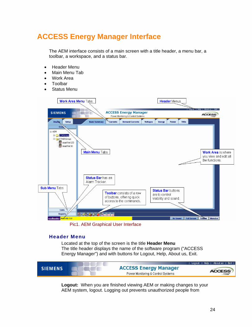
ACCESS Energy Manager Interface The AEM interface consists of a main screen with a title header, a menu bar, a toolbar, a workspace, and a status bar.
• Header Menu • Main Menu Tab • Work Area • Toolbar • Status Menu
Pic1. AEM Graphical User Interface
Header Menu
Located at the top of the screen is the title Header Menu The title header displays the name of the software program ("ACCESS Energy Manager") and with buttons for Logout, Help, About us, Exit.
Logout: When you are finished viewing AEM or making changes to yAEM system
our , logout. Logging out prevents unauthorized people from
24

accessing the AEM controls and features set up for your user ID and
ion r the
Produhttp://www.sea.siemens.com/access to go Access Product catalog page.
password. Help: Help will provide help about the system. About us: It will pop up another window, which will give you informatabout the Product Version Number and Product Identification Number fosystem you have installed. A list box displays information about the copyright laws. About us dialog has a hyper link, which goes to Access
ct catalog page in the corporate web site. You may click on this link
Notes: If you would like to close the window, press 'Close' button from
Exitviewing is trying to close the window - Do you want to close this window?'
If rk on the same.
the About us dialog.
: It will pop up a message box saying that 'The web page you are
If you press 'Yes', then it will close all the program including Internet Explorer browser.
you press 'No', then it will not close the program, you may continue towo
Notes: If you want to run the program again, you need to login again
Main Menu TabLeft below of the title header is the Main Menu tabs
Click on each menu name displays a list of available submenus. You can use the mouse to select the menus and submenus from the Menu Tabs.
25

Wor
ork Area. The Work Area is where you view all the screens and edit them.
Tool
Each command offered on the toolbar is also available from the
k Area he main area in the right center of the AEM screen is the Workspace or T
W bar Below the workspace is the cool & colorful toolbar. The toolbar consists of arow of buttons, offering quick access to the command that is used most frequently. menu bar.
From left to right, the toolbar commands are Project List; Connection List;
vice List; Default Alarm List; Alarm List; Active Alarm List; Data log List;
er the toolbar button; the button's function appears on the status bar at the
en, and on a small label or ToolTip beside the button.
Statcated below the Work Area is the status bar. The status bar has three
buttons No Sound, Full Screen, Toolbar, Menubar.
DeRealtime Trends List; AEM Eventlogs List; Scheduled Jobs List. To choose a command from the toolbar, click on the corresponding toolbar button. For a description of a toolbar command, move the mouse pointerovbottom of the scre us Menu Bar Lo
No Sound : If you click
the No Sound button, will stop the sound for the triggered alarms. You may click the same button to activate the sound or
will hide/unhide the
Header, Main Menu (Tabs) bar, Toolbar and displays the work area in
Toolbar : If you click the Toolbar button, will hide/unhide the toolbar
Menubar : If you click the Menubar button, will hide/unhide the Main Menu (Tabs) bar display.
hat
deactivate the sound.
Full Screen : If you click the Full screen button,
the full screen with the status bar in the below.
display.
W to do next
About AEM Toolbars
26

About AEM Toolbar Like many Windows-based software programs, ACCESS Energy Manager has a toolbar. Because the buttons on the toolbar provide quick access to the AEM functions that you will use most often, spend some time to become familiar with them. The following table describes the function of each button on the AEM toolbar:
Click this buttons... To perform the following function . . .
Project List Opens the Project List. The Project List displays the Project Title, Date Created and Default Project.
Connection List Opens the Connection List. The Connections List displays a list of the AEM connections that are set up for your electrical system.
Device List Opens the Device List. The Device List displays a list of the AEM devices that are set up for your electrical system.
Default Alarm List Opens the Default Alarm List. The Default Alarm List displays a list of default alarms that are set up in AEM.
Alarm List Opens the Alarm List. The Alarm List displays a list of alarms that are configured up in AEM.
Active Alarm List Opens the Active Alarm List. The Active Alarm List displays a list of Active alarm list that are set up in AEM.
Data Logs List Opens the Data Logs List. The Data Logs List displays a list of data logs that are set up for your electrical system.
Realtime Trends List Opens the Realtime Trends List. The Realtime Trends List displays a list of the Realtime trends that are set up in AEM
AEM EventLogs List Opens the AEM EventLogs List. The AEM EventLogs List displays event logs list that displays detailed information about each event occurrence at a specific date and time.
Scheduled Jobs List Opens the Scheduled Jobs List. The Scheduled Jobs List displays a list of Scheduled reports that are set up in AEM.
27

How To... In order to successfully run AEM, you may need to configure some of the settings in your computer. To insure trouble free operation of AEM please read the following. How To...
• Configure Your Computer Display • Configure Your Internet Explorer • Launch AEM • Install IIS 5.0 • Install MSMQ • Configure Your IIS • Troubleshoot AEM with WinPM.Net • Upgrade AEM • UnInstall AEM
28
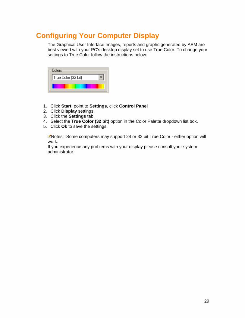
Configuring Your Computer Display The Graphical User Interface Images, reports and graphs generated by AEM are best viewed with your PC's desktop display set to use True Color. To change your settings to True Color follow the instructions below:
1. Click Start, point to Settings, click Control Panel 2. Click Display settings. 3. Click the Settings tab. 4. Select the True Color (32 bit) option in the Color Palette dropdown list box. 5. Click Ok to save the settings.
Notes: Some computers may support 24 or 32 bit True Color - either option will
work. If you experience any problems with your display please consult your system administrator.
29

Configuring your Internet Explorer To ensure trouble free operation of AEM please read each step and you will need to complete the following tasks.
• AutoComplete • Cookie settings • Printing settings
AutoComplete You may find this message, while you login to AEM
To adjust AutoComplete settings You can configure AutoComplete to save and suggest only the information you want. You can choose whether to use AutoComplete for Web addresses, forms and passwords, or not use it all. You can also clear the history for any of these.
1. In Internet Explorer, on the Tools menu, click Internet Options. 2. Click the Content tab. 3. Under Personal information, click AutoComplete. 4. Select the check boxes for the AutoComplete options you want to use.
Notes:
• To avoid the above message dialog, you may have to uncheck 'Prompt me to save passwords'.
• Click Ok button to save this. Cookie settings To change your Cookie settings:
1. In Internet Explorer, on the Tools menu, click Internet Options. 2. On the Privacy tab, move the slider up for a higher level of privacy or down for a
lower level of privacy. 3. Select the cookie settings to Medium.
Notes:
• AEM requires cookies; therefore, if you select a setting that does not allow
30

cookies to be saved on your computer, you might not be able to view our Web pages. In order to work AEM successfully, select the cookie settings to Medium.
Printing Settings In order to Print your Billing reports successfully, you will need to complete the following tasks. To change your Printing settings:
1. In Internet Explorer, on the Tools menu, click Internet Options. 2. Click on the Advanced tab, scroll down to Printing section. 3. Check the Print background colors and image 4. Click Ok to save the changes.
what to do next
Launch AEM
How to launch Access Energy Manager To launch AEM software.
1. In Internet Explorer, on the File menu, click Open. 2. Type http://localhost/aem/index.aspx
Notes: If you have already created a new Default document in the name
of index.aspx, then you can type directly http://localhost/AEM
3. Click Ok to open the Login Page, then follow the link for Login to AEM What to do next
Login to AEM
31

How to Install IIS Installing IIS Internet Information Services is not a typical installation. You can install IIS by using the Add/Remove Programs application in Control Panel. To install IIS
1. Click Start, point to Settings, click Control Panel and start the Add/Remove Programs application.
2. Select Add/Remove Windows Components, scroll down to see Internet Information Services.
3. Check the Internet Information Services (IIS), click Next button and then follow the on-screen instructions to install IIS.
Notes: Please make sure the system is rebooted. To see How to Configure IIS.
How to Install MSMQ Installing MSMQ Microsoft Message Queuing is not a typical installation. You can install MSMQ by using the Add/Remove Programs application in Control Panel. To install MSMQ
1. Click Start, point to Settings, click Control Panel and start the Add/Remove Programs application.
2. Select Add/Remove Windows Components, scroll down to see Microsoft Message Queuing.
3. Check the Microsoft Message Queuing (MSMQ), click Next button and then follow the on-screen instructions to install MSMQ.
About MSMQ Microsoft® Message Queuing (MSMQ) technology enables applications running at different times to communicate across heterogeneous networks and systems that may be temporarily offline. Applications send messages to queues and read messages from queues. MSMQ provides guaranteed message delivery, efficient routing, security, and priority-based messaging. It can be used to implement solutions for both asynchronous and synchronous scenarios requiring high performance.
Notes: Please make sure the system is rebooted after installing MSMQ.
32
Configuring Your IIS • The AEM Installation Program assumes that you have IIS already Installed in
your computer. If you do not have IIS installed in your computer, Installation Program will be terminated. To install IIS, Click here to see How to Install IIS.
• After Installing IIS, follow the Software Installation. • The AEM Installation Program will create a Virtual Directory called AEM in your
IIS Default web site. This directory contains all the needed files to run Access Energy Manager.
Create Default Document The following may be useful for Advanced Users, but it is not necessary: To serve a default document whenever a browser request does specify a document name, follow this procedure. Default documents can be a directory's home page or an index page containing a site document directory listing. To Create A New Default Document
1. Click Start, point to Settings, click Control Panel 2. Click Administrative Tools and then click Internet Services Manager 3. Select the Virtual Directory called AEM in the IIS Default web site
4. Click the Properties toolbar from the top. Result: The AEM properties window will be displayed.
5. Click the Documents tab. 6. Check the Enable Default Documents 7. To add a new default document, click Add. You have to create a New document
in the name of Index.aspx, and then click Ok to save. Notes: Documents are served in the order in which the names appear in
the list. The server returns the first document it finds. To change the search order, select a document and click the arrow buttons.
8. Select the Index.aspx document and click the arrow buttons until it comes to the first place.
33

Special Instructions for Installing AEM on a system with WinPM.Net
Follow the procedure to Troubleshoot this problem. Stop MSSQL Services Exit Service Manager
UnInstall MSDE 1. Navigate to the Control Panel -> Add/Remove Programs -> MSDE 2. Click on Remove to uninstall MSDE
Install ACCESS Energy Manager (AEM)
Insert the AEM CD and follow the instructions. Click here for AEM Software Installation Procedure
Update the configuration for WinPM.Net after installing AEM
1. Go to the command prompt, after C:\ type: “cd Program files\Siemens\WinPM.Net\system\bin” and hit enter key.
2. Type “pmlmsdesetup -cATTACH -nWinPM.NetNOM -dC:\Program Files\Siemens\WinPM.Net\network\NoMDB_data.mdf” and hit enter key.
3. Type “pmlmsdesetup -cATTACH -nWinPM.NetSYSLOG -dC:\Program Files\Siemens\WinPM.Net\syslogs\syslogdb_data.mdf” and hit enter key.
Notes: 1. The above procedure is valid In this case because WinPM.Net was installed in
c:\Program Files. If the installation path is different you will need to change the paths in the above commands accordingly.
2. The paths and commands described under “Update the configuration for WinPM.Net after installing AEM” are not case sensitive.
Need Help?
To request additional information or assistance with ACCESS Energy Manager or any other ACCESS product feel free to contact us. Click here to Contact US
34

How to UnInstall ACCESS Energy Manager 1. Click “Start” on the desktop task bar to view the system menu. 2. Select the “Settings” option. A Submenu will display. 3. Click “Control Panel” to bring up the “Control Panel” window. 4. Click on the “Add/Remove” Programs option. 5. Select “ACCESS Energy Manager” in the programs’ list box, this will enable the “Add/Remove” button. 6. Click the “Add/Remove” button to uninstall ACCESS Energy Manager.
35

Setup Projects
ACCESS Energy Manger will allow you to create more than one project in the system.
Notes: Although for your convenience, AEM provides you with a default project name as AEM When setting up AEM for your electrical system, you may need to add new Project to the system. Once you have created a new project, it will become a default project automatically.
Notes: Further if you add Connections, Devices, Groups, Data Logs, etc., all of them will be stored under the new project. This help topic describes how to setup Projects in AEM. Project Title
Name for the Project that is meaningful to you and the other people who work with your electrical system. Date Created
The Date on which the Project was created. Default Project
Default project is the current project and its status is True. Rest of the projects are not a default project and their status is False.
Notes: To set Default Project, click here Rename Project
Click on this help topic: How to Rename the Project Remove Project
Click on this help topic: How to Remove the Project Open Project
Click on this help topic: How to Open Project Related Topic
• Adding New Projects
36

Creating New Projects
This procedure describes how to add a New Project to your AEM system. Procedure To add a New Project:
1. Login to AEM. 2. Click the Setup tab from the left Menu tabs. 3. Click the Configuration tab. You will find all the setups below the configuration
tab. 4. Click the Setup Projects.
Result: Setup Projects window will be displayed with the existing projects in the Main Screen area.
5. Click the Add New Project button Result: The Add New Project window will be displayed.
6. In the Project Tile field, enter a name for the Project Notes: Enter a name for the Project that is meaningful to you and the other
7. Click Save button to save the Project Result: The Setup Projects window displays the added Project
What to do next After you add a Project to your AEM system, Setup the Connections
people who work with your electrical system.
37

Opening Projects
This procedure describes how to Open an existing Project Notes: This is applicable, if you have more than one project.
Procedure To Open an existing Project.
1. Login to AEM. 2. Click the Setup tab from the left Menu tabs. 3. Click the Configuration tab. You will find all the setups below the configuration
tab. 4. Click the Setup Projects.
Result: Setup Projects window will be displayed with the existing projects in the Main Screen area.
5. Click the Open button to the respective project that you may want to open Result: Default project status will become true for the Open Project; rest of the projects will be set as False
38

Renaming Projects
This procedure describes how to Rename an existing Project Procedure To Rename an existing Project.
1. Login to AEM. 2. Click the Setup tab from the left Menu tabs. 3. Click the Configuration tab. You will find all the setups below the configuration
tab. 4. Click the Setup Projects.
Result: Setup Projects window will be displayed with the existing projects in the Main Screen area.
5. Click the Rename button to the respective project that you want to rename. name Project window will be displayed. Result: The Re
6. In the Project Tile field, enter the new name for the Project Notes: Enter a name for the Project that is meaningful to you and the other ople who work with your electrical system.
7. Click ave button : The Setup Projects window displays the renamed Project.
peS
Result
39

Removing Projects
This procedure describes how to Remove an existing Project Procedure To Remove an existing Project.
1. Login to AEM. 2. Click the Setup tab from the left Menu tabs. 3. Click the Configuration tab. You will find all the setups below the configuration
tab. 4. Click the Setup Projects.
Result: Setup Projects window will be displayed with the existing projects in the Main Screen area.
Click5.
6. Click ject, or press Cancel for not removing the project.
sult: If you have removed the project, You will not be able to see the project in Setup Projects window.
the Remove button to the respective project that you want to remove. Result: The Remove Project window will be displayed.
emove button to remove the Pro R
Re
40

Setup Connections
AEM Connection Types
When setting up AEM for your electrical system, you start by setting up AEM connections (protocols) for communicate to your electrical devices. Devices can be communicated through these connections. To set up an AEM connection to your electrical devices, you basically add the connection in AEM. When adding the connection, you specify the connection name, connection type and other parameters (COM port, Network, Gateway) through which the connection is made. The types of AEM connections that you need to set up are determined by the
• Physical connections through which your electrical devices are connected to your computer
• Communication protocols used by the devices
Therefore, to properly set up AEM connections, you need to understand the physical layout of your electrical system and the communication protocols used by each communicating electrical device in the system. AEM allows you to set up the following types of connections:
• SEAbus/COM SEABUS/COM connection is a connection from a COM port on a AEM computer
to electrical devices that communicate using SEABUS protocol. The SEABUS devices can be connected to the COM port by one of the following
methods:
• Directly (RS-232) • Via an Isolated Multi-Drop Converter (RS-485) • Via some type of modem, such as dial-up, short range, radio, or fiber
optic To allow AEM to monitor and control SEAbus devices connected to a COM port
on your computer, add a SEAbus/COM connection to your AEM system.
• SEAbus/Ethernet SEABUS/Ethernet Converter connection is a network connection from a AEM
computer to SEABUS devices connected to the network through an Ethernet Converter.
To allow AEM to monitor and control SEABUS devices connected to your
network through an Ethernet Converter, add a SEABUS/Ethernet Converter Connection to your AEM system.
41

• Modbus/COM MODBUS/COM connection is a connection from a COM port on a AEM computer
to electrical devices that communicate using MODBUS protocol. The MODBUS devices can be connected to a COM port by one of the following
methods:
• Directly (RS-232) • Via an Isolated Multi-Drop Converter (RS-485) • Via some type of modem, such as dial-up, short range, radio, or
fiber optic To allow AEM to monitor and control MODBUS devices connected to a COM port
on your computer, add a MODBUS/COM connection to your AEM system.
• Modbus/Ethernet MODBUS/Ethernet Converter connection is a network connection from a AEM
computer to MODBUS devices connected to the network through an Ethernet Converter.
To allow AEM to monitor and control MODBUS devices connected to your
network through an Ethernet Converter, add a MODBUS/Ethernet Converter Connection to your AEM system.
• Wireless/File
MODBUS/Ethernet Converter connection is a network connection from a AEM
computer to MODBUS devices connected to the network through an Ethernet Converter.
To allow AEM to monitor and control MODBUS devices connected to your
network through an Ethernet Converter, add a MODBUS/Ethernet Converter Connection to your AEM system.
This help topic describes about each attributes in the Setup Connections in AEM.
Connection Name: Name for the connection (protocol) that is meaningful to you and the other people who work with your electrical system.
Connection Type: Type is a protocol and physical connectivity combination. AEM currently supports 5 types of connections which are described above.
COM Port: COM Port # is the number of the COM port on your computer to which the physical connection is made.
Speed: Speed is the rate at which the devices are communicated. Wireless File Storage Path: This is the location path on the server where all the XML data files are stored for each Wireless device.
42

IP Address: If you are connecting to the internet, your ISP must have provided your server's IP address, and the default gateway's IP address. (The default gateway is the ISP computer through which your computer routes all Internet traffic.)
Notes: You may contact your network administrator for any help on this.
Domain Name System (DNS) : DNS service installed on a computer in your intranet. If your intranet is small, you can use Hosts files on all computers in your network. This step is optional, but it does allow users to use "friendly" text names instead of IP addresses. On the Internet, Web sites usually use the Domain Name System. If you register a domain name for your site, users can type your site's domain name in the DNS field for the browser to contact your site.
Notes: You may contact your network administrator for any help on this.
Socket Port #: The TCP/IP socket port # that the server listens to for the receiving and sending of requests. Port 80 is typically used by HTTP servers and browsers.
Notes: The number of the socket port to use. This must be a value between 1 and 32767. Default If No Entry Found: 80
Total Packets: The total number of data packets requested from all devices on the connection since the last reset.
Notes: A data packet is a set of data bytes from a device. The type of data included in a packet depends on the device being polled.
Total Responses: The number of times AEM got responses for the requests that were made.
Notes: No responses
The number of times AEM requested a data packet from a device but did not receive a response. Some reasons for no response include
• A device lost power • A network connection was lost • Baud rate of the device and the AEM connection port don’t match • The device address assigned to a device does not match the address
set up for that device in AEM • Improper communication wiring
Notes: No responses occur occasionally even under the best
circumstances. A small percentage of no responses relative to the total number of packets requested (1 percent or less) is probably not a problem.
Total errors: The number of data errors that AEM has detected.
43

Notes: Data errors occur when AEM receives a data packet that
contains errors. They occur occasionally even under the best circumstances. A small percentage of data errors relative to the total number of packets requested (1 percent or less) is probably not a problem. A greater percentage may indicate a problem with the COM port or the Baud rate settings.
Simulation Data: By checking this, indicates that the connection is in demo mode and the data for all the devices that fall in this connection will be displayed in demo mode. By default, it is unchecked.
44

Adding Connections
Adding a SEAbus/COM Connection This procedure describes how to add a SEAbus/COM connection to your AEM system. When to perform Add this type of connection to allow AEM to monitor and control devices that communicate using SEAbus protocol and connect to the COM port of your computer by one of the following methods:
• Directly (RS-232) • Via an Isolated Multi-Drop Converter (RS-485)
What you need to know first Before performing this procedure, learn about the AEM Connection Types. Procedure To add a SEAbus/COM connection:
1. Login to AEM. 2. Click the Setup Tab from the Left Menu Tabs to enter the Setup Configuration
Menus. 3. Click the Configuration button. You will find all the setups below the
configuration tab. 4. Click the Setup Connections
Result: Setup Connections window will be displayed with the existing connections in the Main Screen area.
5. Click the Add New Connection button Result: The Add New Connection window is displayed.
6. In the Connection Name field, enter a name for the Connection. Notes: Enter a name for the Connection that is meaningful to you and the
45

other people who work with your electrical system.
OM Connection. the baud rate for the connection.
9. In th r to which the physical connection is made.
10. UnCheck the Simulation Data if you want to communicate to the device in
11ection.
After you add connections to your AEM system, Setup the Devices.
7. From the Connection Type drop-down list, select the Connection type as SEAbus/C
8. From the Select Speed drop-down list, select e COM Port # field, enter the number of the COM port on your compute
realtime. . Click the Save button to save the Connection
Result: The Setup Connection window displays the added conn
What to do next
46

Adding a SEAbus/Ethernet Connection
This procedure describes how to add a SEAbus/Ethernet connection to your AEM system. When to perform Add this type of connection to allow AEM to monitor and control devices that
• Communicate using SEAbus protocol • Connect to the network port of your computer through direct Ethernet or via an
Ethernet Converter or via an Ethernet Gateway. What you need to know first Before performing this procedure, learn about the AEM Connection Types. Procedure To add a SEAbus/Ethernet connection:
1. Login to AEM. 2. Click the Setup Tab from the Left Menu Tabs to enter the Setup Configuration
Menus. 3. Click the Configuration button. You will find all the setups below the
configuration tab. 4. Click the Setup Connections
Result: Setup Connections window will be displayed with the existing connections in the Main Screen area.
5. Click the Add New Connection button Result: The Add New Connection window is displayed.
6. In the Connection Name field, enter a name for the Connection
47

Notes: Enter a name for the Connection that is meaningful to you and the
7. as
8. ddress field, enter the IP Address of the Ethernet Port or Ethernet
other people who work with your electrical system. From the Connection Type drop-down list, select the Connection typeSEAbus/Ethernet Connection.
Result: The Ethernet Port Configuration fields will be displayed. In the IP AGateway or Ethernet Converter.
Notes: If you are not sure about the IP Address, you may select the radio tton DNS (Domain Name System) Name to define the Domain Name in e DNS field.
9. In the field, enter the Domain Name of the Ethernet Gateway or r.
10 M computer te
11. UnCheck the Simulation Data if you want to communicate to the device in
12 lick e Save button to save the Connection sult: The Setup Connection window displays the added connection.
What to do next After you add connections to your AEM system, Setup the Devices.
buth
DNS NameEthernet Converte
. In the Socket Port # field, enter a socket port number that your AEand the Ethernet Gateway or Ethernet Converter will use to negotiacommunications over the network.
realtime. . C th
Re
48
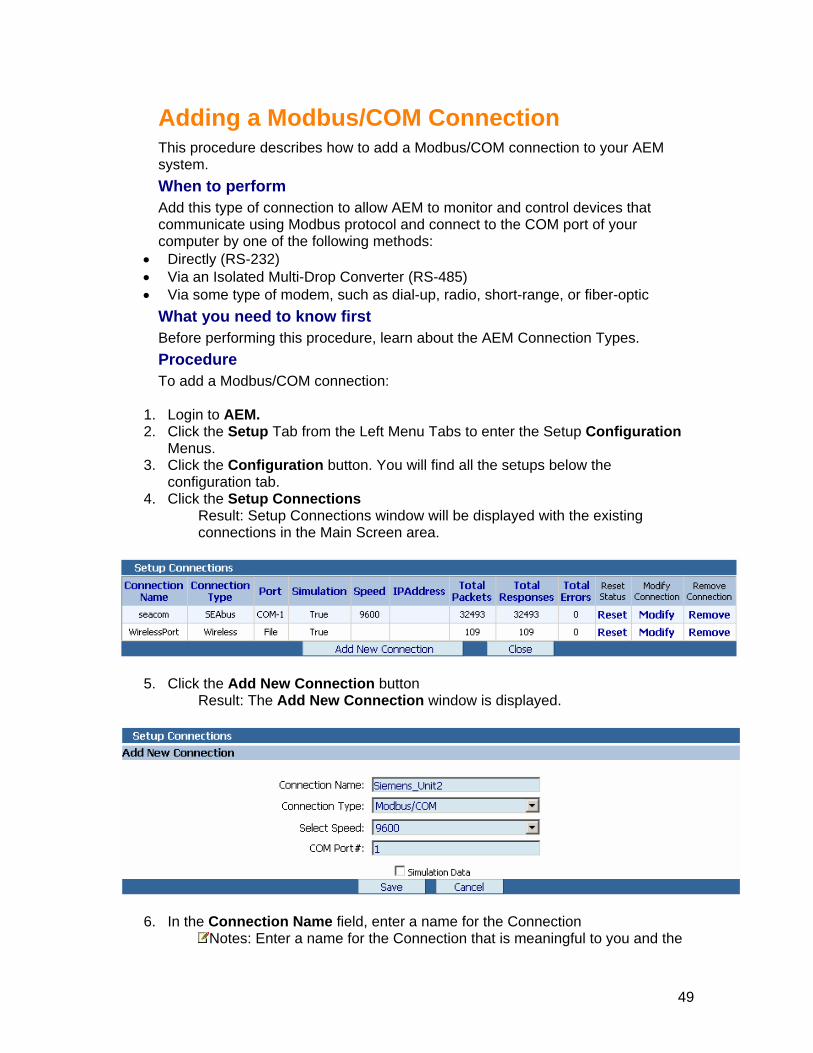
Adding a Modbus/COM Connection
This procedure describes how to add a Modbus/COM connection to your AEM system. When to perform Add this type of connection to allow AEM to monitor and control devices that communicate using Modbus protocol and connect to the COM port of your computer by one of the following methods:
• Directly (RS-232) • Via an Isolated Multi-Drop Converter (RS-485) • Via some type of modem, such as dial-up, radio, short-range, or fiber-optic
What you need to know first Before performing this procedure, learn about the AEM Connection Types. Procedure To add a Modbus/COM connection:
1. Login to AEM. 2. Click the Setup Tab from the Left Menu Tabs to enter the Setup Configuration
Menus. 3. Click the Configuration button. You will find all the setups below the
configuration tab. 4. Click the Setup Connections
Result: Setup Connections window will be displayed with the existing connections in the Main Screen area.
5. Click the Add New Connection button Result: The Add New Connection window is displayed.
In the Con6. nection Name field, enter a name for the Connection Notes: Enter a name for the Connection that is meaningful to you and the
49

other people who work with your electrical system. 7. From Connection Type drop-down list, select the Connection type as
nection. 8. connection. 9. computer to
hysical connection is made. 10. UnCheck the Simulation Data if you want to communicate to the device in
11. Click the Save button to save the Connection Result: The Setup Connection window displays the added connection.
What to do next After you add connections to your AEM system, Setup the Devices.
the Modbus/COM Con
From the Select Speed drop-down list, select the baud rate for the In the COM Port # field, enter the number of the COM port on your which the p
realtime.
50
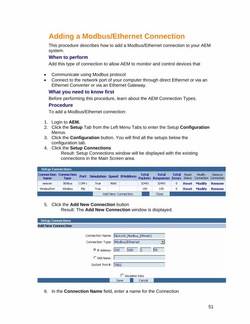
Adding a Modbus/Ethernet Connection
This procedure describes how to add a Modbus/Ethernet connection to your AEM system. When to perform Add this type of connection to allow AEM to monitor and control devices that
• Communicate using Modbus protocol • Connect to the network port of your computer through direct Ethernet or via an
Ethernet Converter or via an Ethernet Gateway. What you need to know first Before performing this procedure, learn about the AEM Connection Types. Procedure To add a Modbus/Ethernet connection:
1. Login to AEM. 2. Click the Setup Tab from the Left Menu Tabs to enter the Setup Configuration
Menus. 3. Click the Configuration button. You will find all the setups below the
configuration tab. 4. Click the Setup Connections
Result: Setup Connections window will be displayed with the existing connections in the Main Screen area.
5. Click the Add New Connection button Result: The Add New Connection window is displayed.
6. In the Connection Name field, enter a name for the Connection
51

Notes: Enter a name for the Connection that is meaningful to you and thother people who work with y
e our electrical system.
7. From Mod
ernet Port Configuration fields will be displayed.
Converter.
the Connection Type drop-down list, select the Connection type as bus/Ethernet Connection. Result: The Eth
8. In the IP Address field, enter the IP Address of the Ethernet Port or EthernetGateway or Ethernet
Notes: If you are not sure about the IP Address, you may select the radiobutton DNS (Domain Name System) Name to define the Domain Nthe DNS field.
ame in
onverter. umber that your AEM computer
and communications over the network.
11 lation Data if you want to communicate to the device in
12Result: The Setup Connection window displays the added connection.
hat to do next After you add connections to your AEM system, Setup the Devices.
9. In the DNS Name field, enter the Domain Name of the Ethernet Gateway or Ethernet C
10. In the Socket Port # field, enter a socket port nthe Ethernet Gateway or Ethernet Converter will use to negotiate
. UnCheck the Simurealtime. Click the Save button to save the Connection .
W
52

Adding a Wireless/File Connection
This procedure describes how to add a Wireless/file connection to your AEM system. When to perform Add this type of connection to allow AEM to monitor and control devices that communicate using Wireless protocol and connect the Wireless Gateway to the COM port of your computer. What you need to know first AEM System has Auto-Configuration feature for Wirless/File Connection Type. Once AEM finds any Wireless devices, then the system automatically adds a Wirelss/File Connection Type. Alternatively, this connection type can be added manually as described below: Before performing this procedure, learn about the AEM Connection Types. Procedure To add a Wireless/File connection:
1. Login to AEM. 2. Click the Setup Tab from the Left Menu Tabs to enter the Setup Configuration
Menus. 3. Click the Configuration button. You will find all the setups below the
configuration tab. 4. Click the Setup Connections
Result: Setup Connections window will be displayed with the existing connections in the Main Screen area.
5. Click the Add New Connection button Result: The Add New Connection window is displayed.
6. In the Connection Name field, enter a name for the Connection. Notes: Enter a name for the Connection that is meaningful to you and
other the
people who work with your electrical system.
53

7. From the Connection Type drop-down list, select the Connection type as Wire
8. In the Wirelss File Storage Path, enter the path for the Wireless Storage xml files. 9. UnCheck the Simulation Data if you want to communicate to the device in
10ection.
What to do next After you add connections to your AEM system, Setup the Devices.
less/File Connection.
realtime. . Click the Save button to save the Connection
Result: The Setup Connection window displays the added conn
54

Modifying Connections
Modifying a SEAbus/COM Connection
This procedure describes how to change the attributes of a SEAbus/COM connection that is already set up in your AEM:
• Connection name The connection name is a name that you assign to the connection.
• Speed Speed is the rate at which the devices will be communicated.
• COM port used by the connection The COM port is the number of the physical COM port to which the devices that the connection serves are connected.
Notes: Once you add a connection to your AEM system, you cannot change its connection type. For example, you cannot change a SEAbus/COM connection to a SEAbus/Ethernet connection. If you no longer need a certain type of connection, delete the connection and add a new connection of the type that you want. Procedure To change the attributes of a SEAbus/COM connection:
1. Login to AEM. 2. Click the Setup Tab from the Left Menu Tabs to enter the Setup Configuration
Menus. 3. Click the Configuration button. You will find all the setups below the
configuration tab. 4. Click the Setup Connections
Result: Setup Connections window will be displayed with the existing connections in the Main Screen area.
5. Click the Modify link to the respective Connection that you want to edit. Result: The Modify Connection window will be displayed.
6. In the Connection Name field, enter a new name for the Connection Notes: Enter a new name for the Connection that is meaningful to you and
the other people who work with your electrical system. Notes: Connection Type cannot change.
7. From the Select Speed drop-down list, select another baud rate for the connection.
8. In the COM Port # field, enter another COM port on your computer to which the physical connection is made.
9. Uncheck the Simulation Data if you want to communicate to the device in real-time.
10. Click the Save button to save the modified Connection Result: The Setup Connection window displays the modified connection.
55
Modifying a SEAbus/Ethernet Connection
This procedure describes how to change the attributes of a SEAbus/Ethernet connection that is already set up in your AEM:
• Connection name The connection name is a name that you assign to the connection.
• IP Address: If you are connecting to the internet, your ISP must have provided your server's IP address, and the default gateway's IP address. (The default gateway is the ISP computer through which your computer routes all Internet traffic.)
Notes: You may contact your network administrator for any help on this.
• Domain Name System (DNS): DNS service installed on a computer in your intranet. If your intranet is small, you can use Hosts files on all computers in your network. This step is optional, but it does allow users to use "friendly" text names instead of IP addresses. On the Internet, Web sites usually use the Domain Name System. If you register a domain name for your site, users can type your site's domain name in the DNS field for the browser to contact your site.
Notes: You may contact your network administrator for any help on this.
• Socket Port #: The TCP/IP socket port # that the server listens to for the receiving and sending of requests. Port 80 is typically used by HTTP servers and browsers.
Notes: The number of the socket port to use. This must be a value between 1 and 32767. Default If No Entry Found: 80
Notes:
Once you add a connection to your AEM system, you cannot change its connection type. For example, you cannot change a SEAbus/Ethernet connection to a SEAbus/COM connection. If you no longer need a certain type of connection, delete the connection and add a new connection of the type that you want. Procedure To change the attributes of a SEAbus/Ethernet connection:
1. Login to AEM. 2. Click the Setup Tab from the Left Menu Tabs to enter the Setup Configuration
Menus. 3. Click the Configuration button. You will find all the setups below the
configuration tab. 4. Click the Setup Connections
Result: Setup Connections window will be displayed with the existing connections in the Main Screen area.
5. Click the Modify link to the respective Connection that you want to edit. Result: The Modify Connection window will be displayed.
6. In the Connection Name field, enter a new name for the Connection Notes: Enter a name for the Connection that is meaningful to you and the
other people who work with your electrical system. Notes: Connection Type cannot change.
56

8. In the IP Address field, enter the new IP Address of the Ethernet Converter. Notes: If you are not sure about the IP Address, you may select the radio
button DNS (Domain Name System) Name to define the Domain Name in the DNS field.
9. In the DNS Name field, enter the Domain Name of the Ethernet Converter. 10. In the Socket Port # field, enter a new socket port number that your AEM
computer and the Ethernet Gateway or Ethernet Converter will use to negotiate communications over the network.
11. Uncheck the Simulation Data if you want to communicate to the device in real-time.
12. Click the Save button to save the modified Connection Result: The Setup Connection window displays the modified connection.
57

Modifying a Modbus/COM Connection
This procedure describes how to change the attributes of a Modbus/COM connection that is already set up in your AEM:
• Connection name The connection name is a name that you assign to the connection.
• Speed Speed is the rate at which the devices will be communicated.
• COM port used by the connection The COM port is the number of the physical COM port to which the devices that the connection serves are connected.
Notes: Once you add a connection to your AEM system, you cannot change its connection type. For example, you cannot change a Modbus/COM connection to a Modbus/Ethernet connection. If you no longer need a certain type of connection, delete the connection and add a new connection of the type that you want. Procedure To change the attributes of a Modbus/COM connection:
1. Login to AEM. 2. Click the Setup Tab from the Left Menu Tabs to enter the Setup Configuration
Menus. 3. Click the Configuration button. You will find all the setups below the
configuration tab. 4. Click the Setup Connections
Result: Setup Connections window will be displayed with the existing connections in the Main Screen area.
5. Click the Modify link to the respective Connection that you want to edit. Result: The Modify Connection window will be displayed.
6. In the Connection Name field, enter a new name for the Connection Notes: Enter a name for the Connection that is meaningful to you and the
other people who work with your electrical system. Notes: Connection Type cannot change.
7. From the Select Speed drop-down list, select another baud rate for the connection.
8. In the COM Port # field, enter another COM port on your computer to which the physical connection is made.
9. Uncheck the Simulation Data if you want to communicate to the device in real-time.
10. Click the Save button to save the modified Connection Result: The Setup Connection window displays the modified connection.
58

Modifying a Modbus/Ethernet Connection
This procedure describes how to change the attributes of a Modbus/Ethernet connection that is already set up in your AEM:
• Connection name The connection name is a name that you assign to the connection.
• IP Address: If you are connecting to the internet, your ISP must have provided your server's IP address, and the default gateway's IP address. (The default gateway is the ISP computer through which your computer routes all Internet traffic.)
Notes: You may contact your network administrator for any help on this.
• Domain Name System (DNS): DNS service installed on a computer in your intranet. If your intranet is small, you can use Hosts files on all computers in your network. This step is optional, but it does allow users to use "friendly" text names instead of IP addresses. On the Internet, Web sites usually use the Domain Name System. If you register a domain name for your site, users can type your site's domain name in the DNS field for the browser to contact your site.
Notes: You may contact your network administrator for any help on this.
• Socket Port #: The TCP/IP socket port # that the server listens to for the receiving and sending of requests. Port 80 is typically used by HTTP servers and browsers.
Notes: The number of the socket port to use. This must be a value between 1 and 32767. Default If No Entry Found: 80
Notes:
Once you add a connection to your AEM system, you cannot change its connection type. For example, you cannot change a Modbus/Ethernet connection to a Modbus/COM connection. If you no longer need a certain type of connection, delete the connection and add a new connection of the type that you want. Procedure To change the attributes of a Modbus/Ethernet connection:
1. Login to AEM. 2. Click the Setup Tab from the Left Menu Tabs to enter the Setup Configuration
Menus. 3. Click the Configuration button. You will find all the setups below the
configuration tab. 4. Click the Setup Connections
Result: Setup Connections window will be displayed with the existing connections in the Main Screen area.
5. Click the Modify link to the respective Connection that you want to edit. Result: The Modify Connection window will be displayed.
6. In the Connection Name field, enter a new name for the Connection Notes: Enter a name for the Connection that is meaningful to you and the
other people who work with your electrical system. Notes: Connection Type cannot change.
59

8. In the IP Address field, enter the new IP Address of the Ethernet Converter. Notes: If you are not sure about the IP Address, you may select the radio
button DNS (Domain Name System) Name to define the Domain Name in the DNS field.
9. In the DNS Name field, enter the Domain Name of the Ethernet Converter. 10. In the Socket Port # field, enter a new socket port number that your AEM
computer and the Ethernet Gateway or Ethernet Converter will use to negotiate communications over the network.
11. Uncheck the Simulation Data if you want to communicate to the device in realtime.
12. Click the Save button to save the modified Connection Result: The Setup Connection window displays the modified connection.
60

Modifying a Wireless/File Connection
This procedure describes how to change the attributes of a Wireless/File connection that is already set up in your AEM:
• Connection name The connection name is a name that you assign to the connection.
• Wireless File Storage Path The path for the Wireless device xml data files.
Notes:
Once you add a connection to your AEM system, you cannot change its connection type. For example, you cannot change a Wireless/File connection to a SEAbus/Ethernet connection. If you no longer need a certain type of connection, delete the connection and add a new connection of the type that you want. Procedure To change the attributes of a Wireless/File connection:
1. Login to AEM. 2. Click the Setup Tab from the Left Menu Tabs to enter the Setup Configuration
Menus. 3. Click the Configuration button. You will find all the setups below the
configuration tab. 4. Click the Setup Connections
Result: Setup Connections window will be displayed with the existing connections in the Main Screen area.
5. Click the Modify link to the respective Connection that you want to edit. Result: The Modify Connection window will be displayed.
6. In the Connection Name field, enter a new name for the Connection Notes: Enter a new name for the Connection that is meaningful to you and
the other people who work with your electrical system. Notes: Connection Type cannot change.
7. In the Wireless File Storage Path field, enter the new path if you wish to. 8. UnCheck the Simulation Data if you want to communicate to the device in
realtime 9. Click the Save button to save the modified Connection.
Result: The Setup Connection window displays the modified connection.
61

Removing Connections
Removing Connections
This procedure describes how to remove an AEM connection. You can remove any type of AEM connection by performing this procedure. Procedure To remove an AEM connection, perform the following procedure:
1. Login to AEM. 2. Click the Setup Tab from the Left Menu Tabs to enter the Setup Configuration
Menus. 3. Click the Configuration button. You will find all the setups below the
configuration tab. 4. Click the Setup Connections
Result: Setup Connections window will be displayed with the existing connections in the Main Screen area.
the Remove link to the respectiv5. Click e connection that you want to delete.
fields disabled.
6. Click the Remove button to remove the connection Warning: If you delete the connection, it will also delete all devices associated with the connection. Result: The AEM deletes the connection and all associated devices.
Result: The Remove Connection window will be displayed with all the
62

Resetting Connections
When to perform Connection status tells you the number of data packets that are requested, number of responses received and the number of data errors occurred so far on a particular connection. Perform this procedure to reset these numbers for any connection. You can also learn certain statistics about the data that AEM is retrieving on a particular connection, such as number of data packets requested, number of responses received and number of data errors. Procedure To reset the status of a connection:
1. Login to AEM. 2. Click the Setup Tab from the Left Menu Tabs to enter the Setup Configuration
Menus. 3. Click the Configuration button. You will find all the setups below the
configuration tab. 4. Click the Setup Connections
Result: Setup Connections window will be displayed with the existing connections in the Main Screen area.
5. Click the Reset link to reset the polling counters of the selected connection to zero.
Result: AEM resets the Packets requested, Response received and Data errors fields to zero.
63

Setup Devices
To set up the devices to your connections, you basically add devices in AEM. When adding the devices, you specify the device name, device type, address. This help topic describes about each function in the Setup Devices in AEM. Device Name
Name for the Device that is meaningful to you and the other people who work with your electrical system. For example, you could give the device a name that describes its location or function. Connection Name
It shows the name of the connection that is meaningful to you and the other people who work with your electrical system. Device Type
It shows the name of the Device Type. For example, 9200 power meter is the device type. Address
Each device connected to the same COM port must have a unique address, which is programmed into the device. Modify Device
Click on this help topic: How to Modify the Device Remove Device
Click on this help topic: How to Remove the Device Related Topic
• Adding New Devices
64

Adding a Device
This procedure describes how to add a device to your AEM system. When to perform Perform this procedure to allow AEM to monitor and control a device that communicates using the SEAbus or Modbus protocol and connects to a COM port or Direct Ethernet or Ethernet Gateway or Ethernet Converter on your computer. What you must do first Before you can add a device, you must add a Connection. Procedure To add a device:
1. Login to AEM. 2. Click the Setup tab from the left Menu tabs. 3. Click the Configuration tab. You will find all the setups below the
configuration tab. 4. Click the Setup Device
Result: Setup Devices window will be displayed with the existing Devices in the Main Screen area.
5. Click the Add New Device button Result: The Add New Device window is displayed.
6. From the Connection Name drop-down list, select the name of the Connection
ld,7. In the Device Name fie enter a name for the device Notes: Give the device a name that is meaningful to you and the oth
people who work with your electrical system. For example, you could ve the device a name that describes its lo
er
cation or function. 8. From the Device Type drop-down list, select a device type. 9. Type the Device address in Address field.
gi
Notes: Each device connected to the same port must have a unique address, which is programmed into the device.
10. Make sure the Poll option is checked to poll the device frequently to get updated data in realtime.
11. Click the Save button. Result: It adds the device to your AEM System. The added device is
65

displayed in the Device Setup window.
What to do next After you add a Device to your AEM system, Setup the Groups to display Realtime data & Standard diagram etc.
66

Modifying a Device
This procedure describes how to change the attributes of a device that is already set up in your AEM:
• Device Name The Device name is a name that you assign to the device
• Address Each device connected to the same port must have a unique address, which is programmed into the device.
Notes:
Once you add a device to the connection in AEM system, you cannot change its Connection Name and Device type. If you no longer need a certain device type, remove the device and add a new device of the type that you want. Procedure To change the attributes of a device setup:
1. Login to AEM. 2. Click the Setup Tab from the Left Menu Tabs to enter the Setup Configuration
Menus. 3. Click the Configuration button. You will find all the setups below the
configuration tab. 4. Click the Setup Device
a. Result: Setup Devices window will be displayed with the existing Devices in the Main Screen area.
5. Click the Modify link to the respective device that you want to edit. 6. Result: The Modify device window will be displayed. 7. In the Device Name field, enter a new name for the device 8. Notes: Give the device a name that is meaningful to you and the other people
who work with your electrical system. For example, you could give the device a name that describes its location or function.
9. Type the new Device address in Address field. 10. Notes: Each device connected to the same port must have a unique address,
which is programmed into the device. 11. Make sure the Poll option is checked to poll the device frequently to get updated
data in realtime. 12. Click the Save button. 13. Result: It updates the device to your AEM System. The modified device is
displayed in the Device Setup window.
67
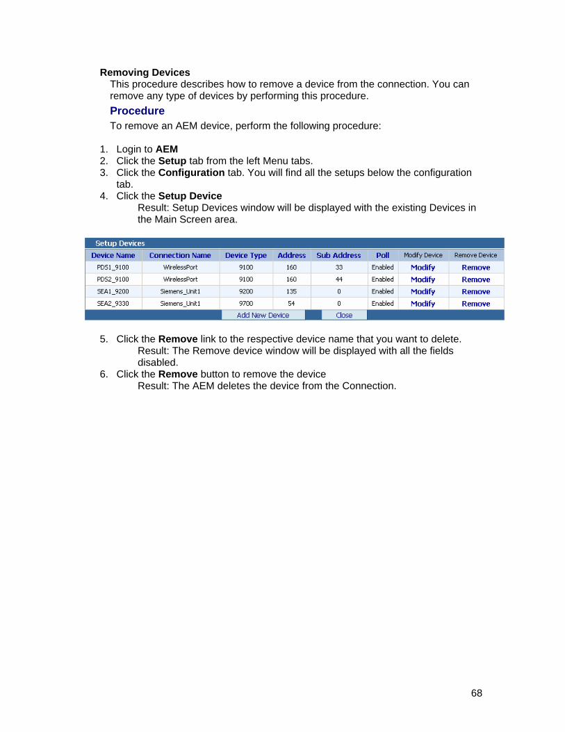
Removing Devices This procedure describes how to remove a device from the connection. You can remove any type of devices by performing this procedure. Procedure To remove an AEM device, perform the following procedure:
1. Login to AEM 2. Click the Setup tab from the left Menu tabs. 3. Click the Configuration tab. You will find all the setups below the configuration
tab. 4. Click the Setup Device
Result: Setup Devices window will be displayed with the existing Devices in the Main Screen area.
5. Click the Remove link to the respective device name that you want to delete. Result: The Remove device window will be displayed with all the fields disabled.
6. Click the Remove button to remove the device Result: The AEM deletes the device from the Connection.
68

Setup Groups
Adding a New Groups
To add a group follow these steps: 1. Login to AEM 2. Click the Setup Tab from the Left Menu Bar to enter the setup Configuration
Menus. 3. Click the Configuration tab. You will find all the setups below the configuration
tab. 4. Click the Setup Groups. This will display any available Groups in the Main
Screen area. Notes: Setup Groups configuration Panel is Vertically separated.
Left - Groups and Sub Groups are displaying in full navigation tree view. Right - Displaying the Setup Groups Menu, through which we can do all the operations related to Groups.
5. Select the Parent Group in the tree and then Click Add Group button.
Specify the new Group Name in the Group nam6. e field.
Notes: Duplicate Group names are not allowed. not allowed.
Empty Group names are
ew Group button to save the Group name or Click Cancel button
lt : If you press 'Add New Group', the new group name that you have
w group is added in the tree view.
Click the Add Nto cancel the operation.
Resugiven will be created under the Parent Group. Now You can see the ne
69

Adding a device to a group
To ad1. Logi2. Click
d a device to a group follow these steps: n to AEM. the Setup tab from the Left Menu Bar to enter the Setup Configuration
Menus. all the setups below the configuration 3. Click the Configuration tab. You will find
tab. 4. Click the Setup Groups. This will display any available Groups in the Main
Screen area. Notes: Setup Groups configuration Panel is vertically separated.
Left - Groups and Sub Groups are displaying in full navigation tree control. Right - Displaying the Setup Groups Menu, through which we can do all the operations related to Groups.
roup in the tree under which the devices need to be add/removed. 5.6. Click the Add/Remove Devices button 7. Use the buttons <<Add or Remove>> to move devices across
selected/unselected device lists. 8. Click Ok button to save the device modifications or Click Cancel button to
cancel the operation. Result : If you press 'Ok', new selected Devices list will be added under the Group, Now You can see the device modifications in the tree view.
Select the g
the
70

Renaming Group
To rename a group follow these steps 1. Login to AEM. 2. Click the Setup tab from the Left Menu Bar to enter the Setup Configuration
Menus. 3. Click the Configuration tab. You will find all the setups below the configuration
tab. 4. Click the Setup Groups. This will display any available Groups in the Main
Screen area. Notes: Setup Groups configuration Panel is vertically separated.
Left - Groups and Sub Groups are displaying in full navigation tree control. Right - Displaying the Setup Groups Menu, through which we can do all the operations related to Groups.
5. First select the group in the tree view that needs to be renamed. 6. Click Rename Selected Group button 7. Specify the new Group Name in the Group name field.
Notes: Root node Group name can be renamed. Duplicate Group names are not allowed. Empty Group names are not allowed.
8. Click the Rename Group button to save the group name or Click the Cancel button to cancel the operation.
Result: If you press 'Rename Group', the selected Group name will be renamed with the new name.
71

Removing Group
To remove a group follows these steps: 1. Login to AEM. 2. Click the Setup tab from the Left Menu Bar to enter the Setup Configuration
Menus. 3. Click the Configuration tab. You will find all the setups below the configuration
tab. 4. Click the Setup Groups. This will display any available Groups in the Main
Screen area. Notes: Setup Groups configuration Panel is vertically separated.
Left - Groups and Sub Groups are displaying in full navigation tree control. Right - Displaying the Setup Groups Menu, through which we can do all the operations related to Groups.
5. Select the group that needs to be removed in the tree. 6. Click Remove Selected Group button 7. Confirm the operation by clicking on the Remove Group button.
Warning: Removing a Group will remove the entire sub Groups and Devices.
72

Setup Alarms
About AEM Alarms
What are alarms? Why are they for? Alarms alert you when something in your electrical system is not working properly. For example, you can set up alarms that alert you when a relay is in the pickup mode, when a breaker trips, or when a device current threshold is exceeded. Alarms can be generated by the AEM software and by certain devices. Authorized users will have the ability to configure alarms and specify actions that must be performed when an alarm condition exists. How do alarms notify me? When setting up an alarm, you also choose how AEM alerts you if the alarm should ever become active. Your choices include
• Displaying a Alarm tracker in the status bar that shows currently triggered alarms and their values at the time they were triggered. If the user clicks on the alarm tracker, the AEM will display the Active Alarm List Screen.
• Recording the alarm in the AEM Event Log • Email Notification - Sending a message to your email
AEM gives you lots of options for setting up alarms! What are the types of AEM alarms? AEM allows you to work with two types of alarms:
• Default alarms ( Default alarms ) • Alarms ( Real alarms/Device specific alarms)
Default alarms A Default alarm applies to every device of a specific type in your electrical system. For example, you can set up a Default alarm that applies to every 9200 device in your system. When working with Default alarms, you can
• Add a Default alarm • Modify a Default alarm • Remove a Default alarm • Reset Default alarms to their factory settings
Alarms A alarm applies to a particular device only. For example, you can set up an alarm that applies only to a particular Siemens 9200 device. When working with real alarms, you can
• Adding an alarm • Modify an alarm • Remove an alarm
Alarm Severity and Alarm Acknowledgement
73

Depending on the level of importance of the alarm, users can configure alarms as either Critical or Non-Critical . Below are characteristics of
Critical Alarms Critical alarms are denoted by the usage of red color text and icons on UI displays related to active alarms. Critical alarms require manual acknowledgement by an authorized user via the Active Alarm screen. The acknowledgement is recorded in the event log with the date and time of the acknowledgement. Non-Critical Alarms Non-Critical alarms are denoted by the usage of amber color text and icons on UI displays related to active alarms. Non-Critical alarms are acknowledged automatically by AEM or manually by an authorized user via the Active Alarm screen. When the current register value of a triggered non-critical alarm no longer satisfies the configured alarm condition, AEM automatically changes the alarm status to a normal non-triggered state and removes it from all active alarm displays. The acknowledgement will be recorded in the event log with the date and time of the acknowledgement.
74
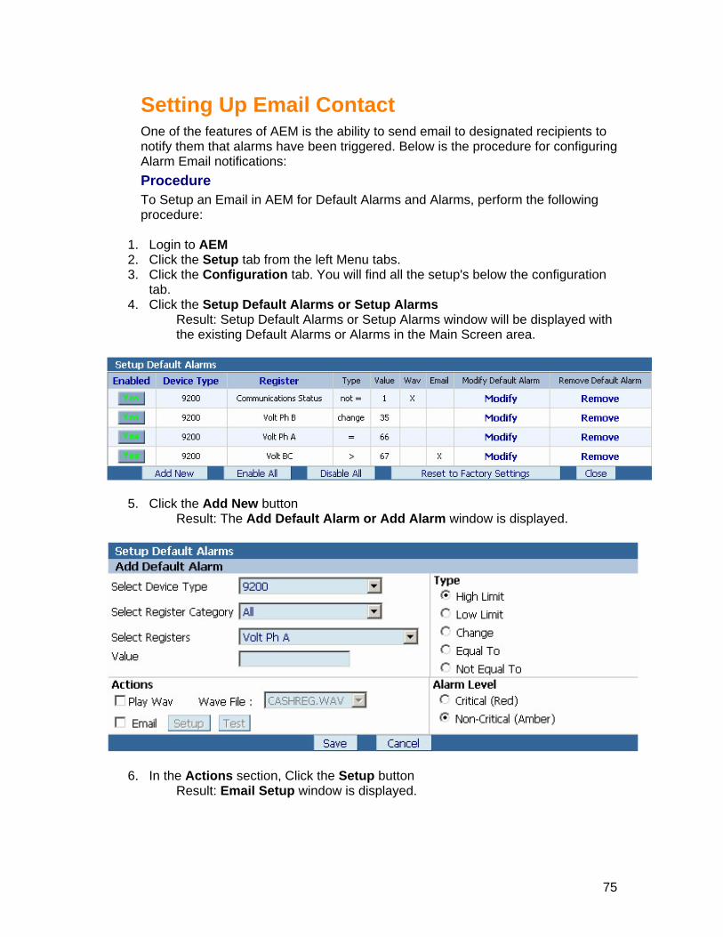
Setting Up Email Contact One of the features of AEM is the ability to send email to designated recipients to notify them that alarms have been triggered. Below is the procedure for configuring Alarm Email notifications: Procedure To Setup an Email in AEM for Default Alarms and Alarms, perform the following procedure:
1. Login to AEM 2. Click the Setup tab from the left Menu tabs. 3. Click the Configuration tab. You will find all the setup's below the configuration
tab. 4. Click the Setup Default Alarms or Setup Alarms
Result: Setup Default Alarms or Setup Alarms window will be displayed with the existing Default Alarms or Alarms in the Main Screen area.
5. Click the Add New button Result: The Add Default Alarm or Add Alarm window is displayed.
e Actions section, Click the Setup button Result: Email Setup window is
6. In th displayed.
75

7. From the Select Contact drop-down list, select the contact person to send email. Notes: If the Select Contact drop-down list is empty, you may create a
new contacts using Manage Contacts button. To learn how to setup contacts, see Setup Contacts
8. In the Message to send text field, type the message which you want to send along with the alarm message.
9. Click the Ok button to save the email setup. Result: The Setup Default Alarm or Setup Alarm window is displayed
76

Setup Default Alarms
Adding a Default Alarm
AEM allows you to add Default alarms for your devices. Default alarms are essentially templates for creating fully activated alarms. A default alarm is an alarm that applies to all devices of a specific type in your electrical system. For example, if you add a default alarm for an 9200 device, the alarm will apply to every 9200 device in your electrical system. AEM comes to you already set up with a default set of default alarms. Although these alarms are needed in most applications, your application may be different. You may need to add some additional default alarms. Another AEM alarm option AEM also allows you to set up alarms for a specific device. For example, you can set up an alarm that applies only to a particular 9200 device in your electrical system and not to any other device. To learn how to set up a device-specific alarm, see Adding a Alarm. What you need to know first Before performing this procedure, learn about AEM alarms. Procedure To add a Default alarm:
1. Login to AEM. 2. Click the Setup Tab from the Left Menu Tabs to enter the Setup Configuration
Menus. 3. Click the Configuration button. You will find all the setup's below the
configuration tab. 4. Click the Setup Default Alarms
Result: Setup Default Alarms window will be displayed with the existing Default Alarms in the Main Screen area.
5. Click the Add New button Result: The Add Default Alarm window is displayed.
77

6. From the Select Device Type drop-down list, select the device for which you want to establish a default alarm.
7. From the Select Register Category drop-down list, select the register category for which you want to establish an alarm.
8. From the Select Register drop-down list, select the register for which you want to establish an alarm.
9. In the Value field, enter the register value on which to base the alarm trigger. 10. In the Type section, select one of the following choices:
If... Then...
You want the alarm to trigger when the register value exceeds the value that you entered in the Value field
Select High limit
You want the alarm to trigger when the register value falls below the value that you entered in the Value field
Select Low limit
You want the alarm to trigger when the register value changes from the value that you entered in the Value field
Select Change
You want the alarm to trigger when the register value is equal to the value that you entered in the Value field
Select Equal to
You want the alarm to trigger when the register value is not equal to the value that you entered in the Value field
Select Not equal to
11. In the Actions section, specify how you want AEM to notify you if the alarm
triggers:
If... Then...
78

You want AEM to play a sound file (WAV)
1. Check the Play WAV check box From the Wave File drop-down list, select the sound file that you want AEM to play.
You want AEM to send email notification
1. Click the Setup button 2. Email setup window will be
displayed for email settings.
You don't want AEM to send email notification
1. Uncheck the Email checkbox.
12. In the Alarm Level section, select which color AEM will use to display the alarm in the alarm list if the alarm becomes active:
If... Then... You want Critical alarms to be displayed in red
Select Critical (Red) radio button.
You want Non-critical alarms to be displayed in Amber
Select Non-Critical (Amber) radio button.
13. Click the Save button.
Result: It adds the new default alarm to your AEM System. The added default alarm is displayed in the Setup Default Alarm window.
79

Modifying Default Alarm
This procedure describes how to change the attributes of existing Default Alarms. When to perform Perform this procedure when you want to make changes to existing Default alarms, such as
• Changing the alarm trigger criteria • Changing how the alarm notifies you
What you need to know first Before performing this procedure, learn about AEM alarms. Procedure To modify a Default alarm:
1. Login to AEM. 2. Click the Setup Tab from the Left Menu Tabs to enter the Setup Configuration
Menus. 3. Click the Configuration button. You will find all the setup's below the
configuration tab. 4. Click the Setup Default Alarms
Result: Setup Default Alarms window will be displayed with the existing Default Alarms in the Main Screen area.
5. Click the Modify link to the respective Default Alarm that you want to edit. Result: The Modify Default Alarm window will be displayed.
80

From the6. Select Device Type drop-down list, select the new device for which
7. From Select Register Category drop-down list, select the new register category for which you want to establish a
8. st, ister for which you
9. ase the alarm trigger.
10 llo
If... Then...
you want to establish a default alarm. the
n alarm. From the Select Register drop-down li
want to establish an alarm. In the Value field, enter the new register value on which to b
select the new reg
. In the Type section, select one of the fo
wing choices:
You want the alarm to trigger when the u
Select High limit register value exceeds the value that yoentered in the Value field
You want the alarm to trigger when the
Select Low limit register value falls below the value that you entered in the Value field
You want the alarm to trigger when the at
Select Change register value changes from the value thyou entered in the Value field
You want the alarm to trigger when the register value is equal to the value that
Select Equal to
you entered in the Value field
You want the alarm to trigger when the register value is not equal to the value that
eld
Select Not equal to
you entered in the Value fi
specify how you want AEM to notify you if the alarm
rs:
If... hen...
11. In the Actions section,trigge
TYou want AEM to play a sounfile (WAV)
d x From the Wave File drop-down list, select
e sound file that you want AEM to play.
1. Check the Play WAV check bo
thYou want AEM to send email not
1. Click the Setup button
or email settings.
ification 2. Email setup window will be displayed f
You don't want AEM to send check the Email checkbox. email notification
1. Un
. In the Alarm Level sectioin the a
12 n, select the alarm larm list if the alarm becomes active:
which color AEM will use to display
81

If... Then... Youdisplayed in
Select Critical (Red) radio button. want Critical alarms to be red
You warms to be displayed in mber
. ant Non-critical Select Non-Critical (Amber) radio buttonalA
13. Click the Save button.
Result: It adds the modified default alarm to your AEM System. The modified default alarm is displayed in the Setup Default Alarm window.
82

Removing Default Alarm
This procedure describes how to remove a default alarm from AEM. Procedure To remove an AEM Default Alarm, perform the following procedure:
1. Login to AEM 2. Click the Setup tab from the left Menu tabs. 3. Click the Configuration tab. You will find all the setup's below the configuration
tab. 4. Click the Setup Default Alarms
Result: Setup Default Alarms window will be displayed with the existing Default Alarms in the Main Screen area.
5. Click the Remove link to the respective Default Alarm that you want to delete. Result: The Remove Default Alarm window will be displayed with all the fields disabled.
6. Click the Remove button to remove the Default Alarm Result: The AEM deletes the default Alarm.
83

Reset to Factory Settings
This procedure describes how to return Default alarms to their factory settings. What you need to know first Before performing this procedure, learn about AEM alarms. Procedure To return Default alarms to their factory settings:
1. Login to AEM. 2. Click the Setup Tab from the Left Menu Tabs to enter the Setup Configuration
Menus. 3. Click the Configuration button. You will find all the setup's below the
configuration tab. 4. Click the Setup Default Alarms
Result: Setup Default Alarms window will be displayed with the existing Default Alarms in the Main Screen area.
Warning: If you click Reset to Factory Settings, it will delete all the added Default Alarms.
5. Click the Reset to Factory Settings button Result: AEM resets to the factory settings for Default alarms.
84

Setup Alarms
Adding a Alarm
AEM allows you to add alarms for your devices. Alarms of this type are associated with a specific device. For example, if you set up a alarm for a particular 9200 device, the alarm will apply only to that device and not to any other devices in your electrical system. Another AEM alarm option AEM also allows you to set up default alarms for your devices. A default alarm is an alarm that applies to all devices of specific type in your electrical system. For example, if you set up a default alarm for an 9200 device, the alarm will apply to every 9200 device in your electrical system. To learn how to set up a default alarm, see Adding a Default Alarm. What you need to know first Before performing this procedure, learn about AEM alarms. Procedure To add an alarm:
1. Login to AEM. 2. Click the Setup Tab from the Left Menu Tabs to enter the Setup Configuration
Menus. 3. Click the Configuration button. You will find all the setup's below the
configuration tab. 4. Click the Setup Alarms
Result: Setup Alarms window will be displayed with the existing Alarms in the Main Screen area.
5. Click the Add New button Result: The Add Alarm window is displayed.
85

6. From the Select Device Type drop-down list, select the device for which you
7. down list, select the register category an alarm.
8. From the Select Register drop-down list, select the register for which you want
9. lue on which to base the alarm trigger. 10 of the following choices:
If...
want to establish a alarm. From the Select Register Category drop-
for which you want to establish
to establish an alarm. In the Value field, enter the register va. In the Type section, select one
Then... You want the alarm to trigger when the register value exceeds the value
Select High that you
entered in the Value field.
limit
You want the alarm to trigger when the Select Low limit register value falls below the value that
u entered in the Value field. yo
You want the alarm to triggregiste
er whr value changes from
you entered in the Value fiel
en the Select Change the value that d.
You want the alarm to trigger wh register value is equal to the value tyou entered in the Value field.
en the hat
Select Equal to
You want the alarm to trigger whe he register value is not equal to the value that
u entered in the Value field.
Select Not equal to n t
yo
11. In the Actions section, specify how you want AEM to notify you if the alarm
triggers:
hen...
If... TYou w nd file (W From the Wave File drop-down list, select
the sound file that you want AEM to play.
ant AEM to play a souAV)
1. Check the Play WAV check box
86

You want AEM to send email notification
1. Click the Setup button 2. Email setup window will be
displayed for email settings.
You don't wemail notification
the Email checkbox.
ant AEM to send 1. Uncheck
12. In the Alarm Level section, select which color AEM will use to display the alarm
he alarm becomes active:
If... Then...
in the alarm list if t
You want Critical alarms to be displayed in red
Select Critical (Red) radio button.
You want Non-critical alarms to be displayed in Amber
Select Non-Critical (Amber) radio button.
13. Click the Save button.
Result: It adds the new alarm to your AEM System. The added alarm is displayed in the Setup Alarm window.
87

Modifying Alarms
This procedure describes how to change the attributes of an Alarm that is already configured in AEM: When to perform Perform this procedure when you want to make changes to an existing alarm, such as
• Changing the alarm trigger criteria • Changing how the alarm notifies you
What you need to know first Before performing this procedure, learn about AEM alarms. Procedure To modify an alarm:
1. Login to AEM. 2. Click the Setup Tab from the Left Menu Tabs to enter the Setup Configuration
Menus. 3. Click the Configuration button. You will find all the setup's below the
configuration tab. 4. Click the Setup Alarms
Result: Setup Alarms window will be displayed with the existing Alarms in the Main Screen area.
5. Click the Modify link to the respective Alarm that you want to edit. Result: The Modify Alarm window will be displayed.
88
From the Select Device Type drop-doyou want to establish an alarm
6. wn list, select the new device for which .
7. From er h a
8. the new register for which you
9. In the Value field, enter the new register value on which to base the alarm trigger.
If... Then...
the Select Register Category drop-down list, selecategory for which you want to establis
From the Select Register drop-down list, select want to establish an alarm.
ct the new registn alarm.
10. In the Type section, select one of the following choices:
You want the alarm to trigger when the value
d in the Value field
Select High limit register value exceeds theentere
that you
You want the alarm to triregiste
gger whr value falls below the va
you entered in the Value field
en the Select Low limit lue that
You want the alarm to trregister valu
igger whe changes from the value that
you entered in the Value field
en the Select Change
You want the alarm to trigger when the egister value is equal to the value that
Select Equal to r
u entered in the Value field yo
You want the alarm to trigregister valu
ger whee is not equal to the value that
e fiel
n the Select Not equal to
you entered in the Valu d
11. In the Actions section, specify how you want AEM to notify you if the alarm
If...
triggers:
Then...
89
You want Afile (WAV)
lay WAV check box From the Wave File drop-down list, select the sound file that you want AEM to play.
EM to play a sound 1. Check the P
You want AEM to send email notification
1. Click the Setup button 2. Email setup window will be
displayed for email settings.
You don't want AEM to send email notification
1. Uncheck the Email checkbox.
12. In the Alarm Level section, select which color AEM will use to display the alarm in the alarm list if the alarm becomes active:
If... Then... You want Critical alarms to be displayed in red
Select Critical (Red) radio button.
You want Non-critical alarms to be displayed in Amber
Select Non-Critical (Amber) radio button.
13. Click the Save button.
Result: It adds the modified alarm to your AEM System. The modified alarm is displayed in the Setup Alarm window.
90

Removing Alarms
This procedure describes how to remove an alarm from AEM. Procedure To remove an AEM Alarm, perform the following procedure:
1. Login to AEM 2. Click the Setup tab from the left Menu tabs. 3. Click the Configuration tab. You will find all the setup's below the configuration
tab. 4. Click the Setup Alarms
Result: Setup Alarms window will be displayed with the existing Alarms in the Main Screen area.
5. Click the Remove link to the respective Alarm that you want to delete. Result: The Remove Alarm window will be displayed with all the fields disabled.
6. Click the Remove button to remove the Alarm Result: The AEM deletes the Alarm.
91

Setup Data logs
To set up the data logs in AEM, you basically add data logs. When adding the data logs, you specify the device name, device category, selected registers, start date/time, stop date/time, log Interval and log Interval offset. To learn more about data logs, click here about data logs. This help topic describes about each function in the setup Data Logs in AEM. Modify Log
Click on this help topic: How to Modify the Data logs Remove Log
Click on this help topic: How to Remove the Data logs View Log
Click on this help topic: How to View the Data logs Related Topic
• Add New Data Logs • About Data Logs
92

About Data logs
What is a data log? What do I use it for? A data log is a historical or trend log of device data over a period of time. You typically use the data log data to periodically generate graphs of power demand and power factor. How do I capture data logs? You can use AEM to directly capture the data logs. How do I use AEM to directly capture data logs? To set up AEM to capture a data log, you perform a simple procedure that allows you to specify . . .
• Which device data to include in the data log • Start and stop times of the data log • How often AEM takes a sample of the data, referred to as the sampling interval
How do I view data logs? You can view stored data logs files. This allows you to specify which data log you want to view and to Select Device-Register Combinations to be graphed:
93

Adding new Data logs
This procedure describes how to set up AEM to capture a data log. When to perform Perform this procedure when you need a historical or trend log of device data during normal system operation. You can use the data to periodically generate graphs of power demand and power factor. What you need to know first Before performing this procedure, learn about data logs.
• Data Log Name Name for the Data log that is meaningful to you and the other people who work with your electrical system. For example, you could give the data log name that describes its device and register.
• Start Date/Time It allows you to start capturing data on a specific date and time
• Stop Date/Time It allows you to stop capturing data on a specific date and time
• Log Interval It allows you to capture the data using a different sampling rate
• Log Interval Offset It allows you to capture the first data sample at a time that is offset from the start Data Log time by a specified amount
• Select Device It shows all the available devices in AEM. You can select the device from which you want to capture data.
• Select Category It shows all the available functionality for the particular device in AEM, You can select the device category from which you want to capture data.
• Available Registers It shows the available registers in the selected device type. you can specify which data you want to capture by selecting the device registers that contain the data.
• Selected Registers It shows the added registers from the available registers. You may want add or remove the registers from the selected registers list for generating the data log.
Procedure To set up AEM to capture a data log:
1. Login to AEM. 2. Click the Setup tab from the left Menu tabs. 3. Click the Configuration tab. You will find all the setups below the
configuration tab. 4. Click the Setup Data Logs
Result: The Setup Data Logs window is displayed.
94

5. Click the Add New Data Log button Result: The Add New Data Log window is displayed.
6. From the Data Log Name field, enter a name for the Data Log Notes: Enter a name for the Data Log that is meaningful to you and
the other people wime:
Th .
ho work with your electrical system. stop a7. To define AEM to start and
If...
c pturing data on a specific date and t
en .. You want AEM to start capturing data on a specific date and time
1. . Check the Enable Start Date/Time2. Enter a start date in the field
labeled, Start Date. Date format: MM/DD/YYYY.
Enter a start time in the field labeled, Start Time. Time Format: h:m:s.
You want AEM to stop capturing 1. Check the Enable Stop Date/Time.
95

data on a specific date and time ter a stop date in the field
Enter a stop time in the field labeled, Stop im T
2. Enlabeled, Stop Date. Date format: MM/DD/YYYY.
T e. ime Format: h:m:s.
8. In the Log Interval area,
perfor s:
If... Then.
m one or both of the following option
.. You want AEM to capture the data using ifferent sampling rate
ter the desired sampling rate in the Log Interval field. Time Format: h:m:s. En
a d
You want AEM to capture the first datoffset ftim
1. Check the box Enable Interval
2. Enter the offset time in the field
h:m:s.
a sample at a time that is rom the start Data Logs
Offset
e by a specified amount Interval Offset. Time Format:
From the Select Devicecapture data.
9. drop-dow ou want to
10. From the Select Category dro ce category from which you want to capture data.
11. Specify which data you want to capture by selecting the device registers that
Then.
n list, select the device from which y
p-down list, select the devi
contain the data: If... ..
You want to add an available register to the Selected Registers list
1. rs list,
2.Resul gister is displayed on
e Selected Registers list.
On the Available Registehighlight the register that contains the data you want to capture.
Click the Add button. t: The added re
thYou want to remove a registfrom the Selected Registers
er list then
d Registers
list and returns it to the Available Registers list.
1. Select the register on the Selected Registers list, andclick the Remove button.
Result: AEM removes the selectedregister from the Selecte
You want to remregisters from thRegis
es all the registers from the Selected Registers list and returns it to the
ove all the e Selected
1. Click the Remove All button. Result: AEM remov
ters list
Available Registers list.
12 ve button.
stem. The added data log is displayed in the Setup Data Logs window.
. Click the SaResult: It adds the data log to your AEM Sy
96

Viewing Data logs
This procedure describes how to view a data log in AEM. You can view any data logs by performing this procedure.
To view a data log, perf
1. Login to AEM 2. Click the Setup tab from the left Menu tabs. 3. Click the Configuration tab. You will find all the setups below the configuration
tab. 4. Click the Setup Data logs
Result: Setup Data Logs window will be displayed with the existing Data logs
Procedure orm the following procedure:
5. Click the View link to the respective data log that you want to view. Result: The Data log Viewer window will be displayed with a Graph and selected device register options.
6. ions to be graphed from the Select Select the Device-Register Combinat Device List Register
Notes: Use the Shift and Ctrl key for selecting more than one register from the list.
7. After selecting the Device-Registers, Click the Refresh Graph button Result: Graph is displayed with new Device-Registers combinations that you have selected now.
8. Click the Close button for exiting from the Data Log Viewer.
97

Modifying Data logs
This procedure describes how to change the attributes of a data log that is already set up in your AEM:
• Start Data/Time It allows you to change the start capturing data on a specific date and time
• Stop Date/Time It allows you to change the stop capturing data on a specific date and time
• Log Interval It allows you to change the data using a different sampling rate
• Log Interval Offset It allows you to change the first data sample at a time that is offset from the start Data Logs time by a specified amount
Notes:
Once you add a data log in AEM system, you cannot change its data log name, device name, device category. You will not be able to add or remove the registers to the selected registers. If you no longer need a certain data log, remove the data log and add a new data log or you can create a new data log without deleting the existing one. Procedure To change the attributes of a data log:
1. Login to AEM. 2. Click the Setup Tab from the Left Menu Tabs to enter the Setup
Configuration Menus. 3. Click the Configuration button. You will find all the setups below the
configuration tab. 4. Click the Setup Data Logs
Result: Setup Data Logs window will be displayed with the existing Data Logs in the Main Screen area.
. fy Da l tributes
6. To modify start and stop capturing
5. Click the Modify link toResult: The Modiare disabled.
the respective data log that you want to editome atta og window is displayed with s
data on a specific date and time:
98
If... Th .en .. You want AEM to start capturing data on a specific date and time
Time. 2.
ate. Date format:
labeled, Start Time. Time Format: h:m:s.
1. Check the Enable Start Date/Enter a start date in the field labeled, Start DMM/DD/YYYY.
Enter a start time in the field
Youdata on a s cific date and time 2. Enter a stop date in the field
eled, Stop Date. Date format:
, Stop Time. Time Format: h:m:s.
want AEM to stop capturing 1. Check the Enable Stop Date/Time. pe
labMM/DD/YYYY.
Enter a stop time in the field labeled
7. To modify the Log Inte
If...
rval, perform both of the following options:
Then.
one or
.. You want AEM to capture the data using a different sampling rate
Enter the desired sampling rate in the Log terval field. Time Format: h:m:s. In
You want AEM to capture the first data sample at offset from the stime by a specif t
1. Check the box Enable Interval
Interval Offset. Time Format: h:m:s.
a time that is tart Data Log ied amoun
Offset 2. Enter the offset time in the field
8. Click the Save button.
Result: It saves the modified attributes in the data log to your AEM System. The modified data log is displayed in the Setup Data Logs window.
99

Removing Data logs
This procedure describes how to remove a data log from the AEM. You can remove any data log by performing this procedure. Procedure To remove a data log, perform the following procedure:
1. Login to AEM 2. Click the Setup tab from the left Menu tabs. 3. Click the Configuration tab. You will find all the setups below the configuration
tab. 4. Click the Setup Data logs
Result: Setup Data Logs window will be displayed with the existing Data log in the Main Screen area.
5. Click the Remove link to the respective data log that you want to delete. Result: The Remove data log window will be displayed with all the fields disabled.
6. Click the Remove button to remove the data log. Result: The AEM deletes the selected data log.
100

Export Data logs
This procedure describes how to export Data logs to an Excel spread sheet. What you need to know first Before performing this procedure, learn about data logs. Procedure To set up AEM to export data log:
1. Login to AEM. 2. Click the Setup tab from the left Menu tabs. 3. Click the Configuration tab. You will find all the setups below the
configuration tab. 4. Click the Setup Data Logs
Result: The Setup Data Logs window is displayed.
5. Click the Export link to the respective data log that you want to export. Result: The Data Log Export Configuration window will be displayed.
he File Name field, enter file name that you want to store the data logs. ect the
6. In t7. l8. ic
Se Start Date/Time and the Stop Date/Time for to export the data logs. Cl k the Export Data Log button.
101

Result: The data log is now being exported.
• You may click View Exported Datalogs button to view the exported data logs.
• You may click Datalog Page button to go back to the data log setup page. • You may click Close button to leave data logs.
What to do next
Viewing Exported Datalog List
102

Setup Realtime Trends
About Realtime Trends
What is a Realtime Trend? What do I use it for? A Realtime trend is a graphical display of real-time data retrieved from AEM devices. You typically use the realtime data to generate a graphical display to show the movement of one to four realtime registers over time. How do I capture the Realtime Trend? The trending period will begin as the user begins viewing the trending display and will continue as long as the screen is being actively displayed. Once the user leaves the real-time trending page, the trending period will end. Subsequent visits to the real-time trending page will result in the initiation of a new trending period. Each realtime trending screen consist of one to four trends. Each trend in the screen is displayed in an hour span that refreshes every 30 seconds. How do I save the Realtime Trend output? To save the realtime trend output in an image file
• Right click on the trend graphics output. • Select Save picture as for saving the trend graphics in an image file.
How do I Print the Realtime Trend output? To print the realtime trend output
• Right click on the trend graphics output. • Select Print picture for to print the trend graphics.
How do I see the realtime trend associated data in a table format? To see the realtime trend associated data in a table format
• Left mouse click on a graphic. • A window will be displayed with a realtime trend associated data in a table format. • You may close this window, if you don't want to see.
103

Adding Realtime Trends
This procedure describes how to set up realtime data to generate the trending output in a line graph When to perform Perform this procedure when you need a graphical display of real-time data retrieved from AEM devices. You typically use the realtime data to periodically generate the trending output in a line graph. What you need to know first Before performing this procedure, learn About Realtime Trends Procedure To set up AEM to generate a realtime trending.
1. Login to AEM. 2. Click the Setup tab from the left Menu tabs. 3. Click the Configuration tab. You will find all the setups below the
configuration tab. 4. Click the Setup Realtime Trends
Result: The Setup Realtime Trends window is displayed.
5. Click the Add Trend button Result: The Realtime Trending Configuration window is displayed.
104

6. Name the Realtime Trending display. Notes: Enter a name f that is
meaningful to you and the other people who work with your electrical
x, select a d nerate the
8. Specify which data you want to capture by selecting the device registers that contain the realtime data:
or the Realtime Trending Display
system. 7. In the Devices list bo
realtime trend. evice for which you want to ge
Notes: Select up to 4 Device/Register pairs per display
If...
Then... You want to add an available register to the Selected Device/Registers
1. On the Available Registers list, highlight the register that contains the data you want to capture.
register is displayed on the Selected Device/Registers pairs for
pairs 2. Click the Add button. Result: The added
trending display You want to remfrom the SelecteDevice/Registers pairs
Selected Device/Registers pairs, and then click the Remove button.
Result: AEM removes the selected register from the Selected Device/Registers pairs and returns it to the Available Registers list.
ove a register d
1. Select the register on the
You want to remove all the registers from the Selected Device/Registers pairs
1. Click the Remove All button. Result: AEM removes all the registers from the Selected
105
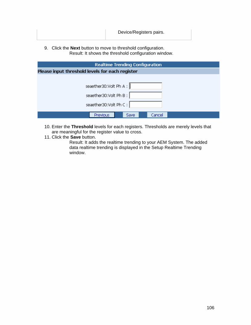
Device/Re
gisters pairs.
Click the Next button to move to threshold configuration.
Result: It shows the threshold configuratio9.
n window.
10. Enter the Threshold levels for each registers. Thresholds are merely levels that are meaningful for the register value to cross.
11. Click the Save button. Result: It adds the realtime trending to your AEM System. The added data realtime trending is displayed in the Setup Realtime Trending window.
106
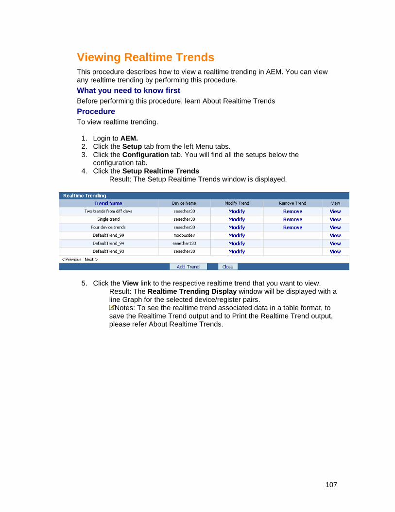
Viewing Realtime Trends
This procedure describes how to view a realtime trending in AEM. You can view any realtime trending by performing this procedure.
eed to know first Realtime Trends
T
nu tabs. he
confi4. Click e Setup Realtime Trends
Result: The Setup Realtime Trends window is displayed.
What you nBefore performing this procedure, learn About Procedure
o view realtime trending.
1. Login to AEM. 2. Click the Setup tab from the left Me3. Click the Configuration tab. You will find all the setups below t
ration tab. gu th
5. Click . d with a
the View link to the respective realtime trend that you want to viewResult: The window will be displayeRealtime Trending Displayline Graph for the selected device/register pairs.
Notes: To see the realtime trend associated data in a table format, tsave the Realtime Trend output and to Print the Realtime Trend outpuplease re
o t,
fer About Realtime Trends.
107

ModifyinThis procedure de
g Realtime Tscribes how to c nd that is
already set up in AEM: Procedure To change the attributes of a Real
b from the tab. low the
configuration tab. 4. Click the Setup Realtime Trends
Result: The Setup Realtime Trends window is displayed.
rends
rehange the attributes of a Realtime T
time Trend:
1. Login to AEM. 2. Click the Setup ta3. Click the Configuration
left Menu tabs. You will find all the setups be
5. Click the Modify link to the respective realtime trend that you want to edit. Result: The Modify realtime trend configuration window is displayed
Notes: If you have chosen the Default Trends, then some of the attributes are disabled and you will not be able to modify them.
6. Enter a new Name for the realtime trending display. Notes: Enter a new name for the Realtime Trending Display that is
meaningful to you and the other people who work with your electrical system.
7. In the Devices list box, select a new device for which you want to generate the realtime trending.
8. Specify which data you want to capture by selecting the device registers that contain the realtime data:
Notes: Select up to 4 Device/Register pairs per display
If... Then... You want to add an available register to the Selected Device/Registers pairs
1. On the Available Registers list, highlight the register that contains the data you want to capture.
2. Click the Add button. Result: The added register is displayed on the Selected Device/Registers pairs for trending display
108

You wfrom Devic
e ice/Registers pairs,
ted Device/Registers pairs and returns
list.
ant to remove a register the Selected
1. Select the register on thSelected Dev
e/Registers pairs and then click the Remove button. Result: AEM removes the selected register from the Selec
it to the Available Registers
You want to remove all the regDe
1. Click the Remove All button. removes all the
Device/Registers pairs.
isters from the Selected Result: AEMvice/Registers pairs registers from the Selected
9. Click e Next button to move to threshold configuration. Result: It shows the threshold configuration window.
10. Enter the new Threshold levels for each registers. 11. Click the Save button.
Result: It modifies the realtime trending to your AEM System. The modified realtime trending is displayed in the Setup Realtime Trending window.
th
109
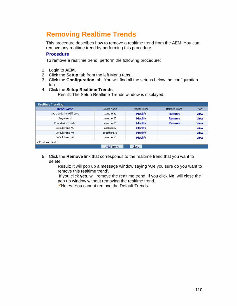
Removing Realtime Trends
realtime trend from the AEM. You can procedure.
1.2.3. tion
4.
This procedure describes how to remove a remove any realtime trend by performing thisProcedure To remove a realtime trend, perform the following procedure: Login to AEM. Click the Setup tab from the left Menu tabs.
all the setups below the configura Click the Configuration tab. You will find tab.
Click the Setup Realtime Trends Result: The Setup Realtime Trends window is displayed.
5. Click the Remove link that corresponds to the realtime trenddelete.
that you want to
Result: It will pop up a message window saying 'Are you sure do you want toremove this realtime trend'. If you click yes, will remove the realtime trend. If you click No, will close the pop up window without removing the realtime trend.
Notes: You cannot remove the Default Trends.
110

Set
em Diagrams
g nts. AEM
graphical features that allow you to view summary and detailed o control your electrical devices. See Sample Diagram!
w many system diagrams do I need? Some electrical systems a tems require several system diagrams, or in some cases, a hierarchy of system diagrams. In fact, the typical ele trical system requires a high-level system dsubsystem e the dHTo create system diagrams, you
1. Sketch out on paper a series of diagrams that illustrate your electrical power monitoring system.
2. Use a popular graphics package to create detailed drawings from the sketches. 3. Add system diagrams to AEM. These diagrams use the drawings as their
background. 4. Customize the system diagrams by adding AEM elements.
To create the system diagrams for your electrical system, begin by sketching out on paper a series of diagrams that roughly illustrate your electrical system. You might, for example, start with a sketch that illustrates your overall electrical system, and then create more detailed sketches of each subsystem.
After you complete the sketches, create detailed and accurate drawings of each sketch in a popular graphics program, such as Adobe Photoshop, Visio, or Microsoft Paint. And be sure to save the drawings in one of the file formats accepted by AEM i.e. BMP, JPG, GIF. By the way, these drawings are referred to as background graphics.
When you have completed the background graphics, you are ready to add system diagrams to your AEM system. Each system diagram that you add will use one of the background graphics that you created as its background.
The final step is to customize your system diagrams for your power monitoring and control needs by adding AEM elements to them. For example, you can add elements that allow you to display summary or detailed electrical data, to operate relays, to start up and shut down equipment, and to jump to other system diagrams.
up Diagrams
About SystWhat is a System Diagram? A system diagram is a graphical representation of your electrical power monitorinsystem or a portion of it upon which are superimposed AEM elemeelements are electrical data and tHo
are simple enough to require only one system diagram to dequately represent their devices and connections. However, most sys
ciagram, or 50,000-feet view, that illustrates the interconnections between the
s, and then a series of more detailed system diagrams that illustratd connections in each subsystem. evices an
ow do I create system diagrams? perform four basic tasks:
111
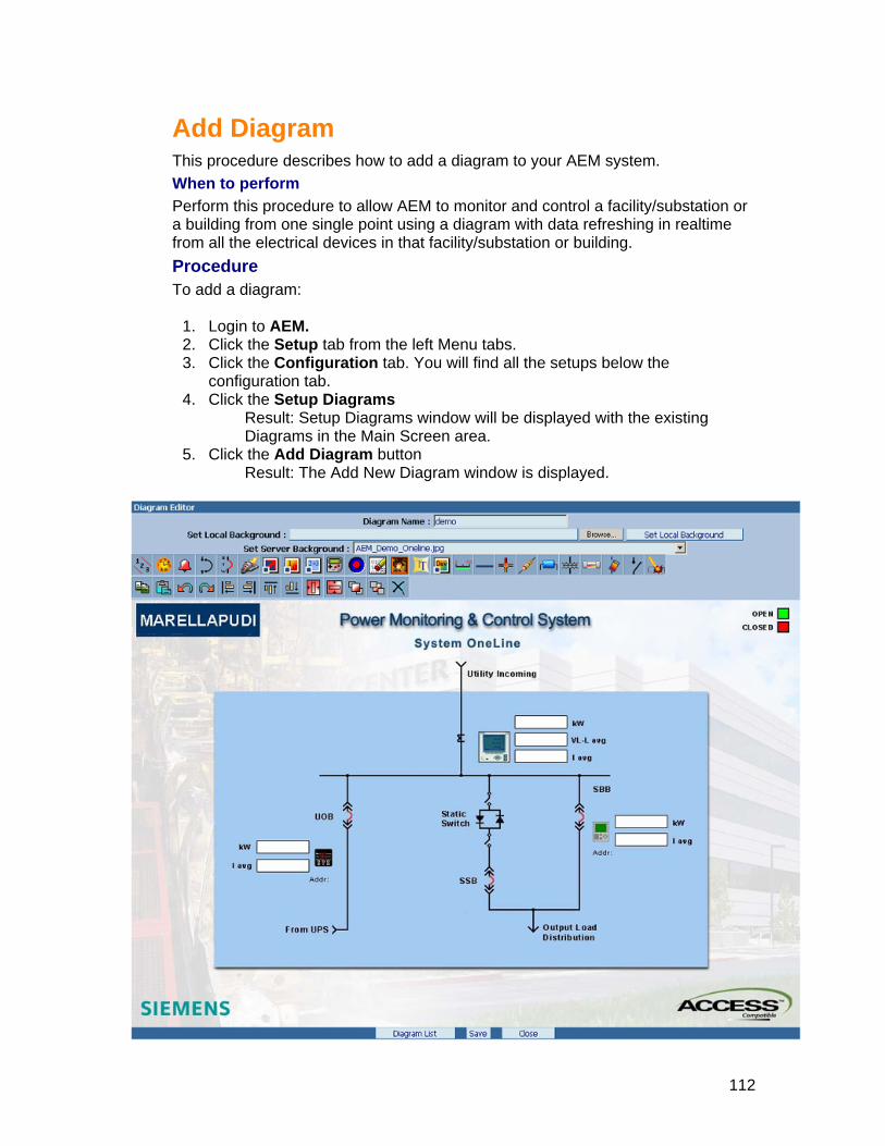
ATWPerfo llow AEM to monitor and control a facility/substation or a e from all the electrical devices in that facility/substation or building. PTo add a d
1. Login AEM. 2. Click e Setup tab from the left Menu tabs.
. Click e Configuration tab. You will find all the setups below the configuration tab.
4. Click the Setup Diagrams Result: Setup Diagrams window will be displayed with the existing Diagrams in the Main Screen area.
5. Click the Add Diagram button Result: The Add New Diagram window is displayed.
dd Diagram
his procedure describes how to add a diagram to your AEM system. hen to perform
rm this procedure to a building from one single point using a diagram with data refreshing in realtim
rocedure iagram:
to th th3
112

6. In the Diagram Name field, enter a name for the diagram
choosing from your local computer or
the
AEM Element Overview for more information about all the
M System. The added diagram is e Diagram Setup window.
7. Select a background image either byfrom the server.
8. Now select Hotspots or Electrical elements of your choice by clicking onspecial toolbar icons.
9. Please refertoolbar icons.
10. Click the Save button. Result: It adds the diagram to your AEdisplayed in th
113

Add & Edit Ele
AEM ElemeAEM elements allow
that. . .
splay specified d• Display specified d• Display breaker st• Control a device • p to a real-tim
oes on!
The following table plearn how to add anprovided.
Elements..
ments
nt Overview
you to customize your system diagrams with graphical features
• Di evice data in digital form evice data in analog form
atus
Jum
e data window or another system diagram
The list g
rovides a task-oriented description of each AEM element. To d configure (or edit) these elements, click on the links
Click this To perform the following function . . .
Numeric ical Displays the value of a specified device register in alphanumer
form. The value may be a number or character string. AEM updates this value each time it polls the device
Analog
nce the
Displays the value of a specified device register in analog form. To display the value in analog form, AEM uses a dial gauge with a pointer. You can configure the gauge with drag hands to indicate the minimum and maximum values of the device register silast reset. AEM updates the value that the gauge displays each time it polls the device.
Alarm Displays the chosen image to show when the alarm is active. You may also choose different image when the alarm is inactive. First, you have to have alarm setup through Setup Alarms for using this element.
Trip Unit Displays a color-coded breaker symbol that indicates the status of a breaker. You can configure the breaker element as either a square or a standard breaker symbol. The color of the breaker element, which you can configure, denotes the breaker status: open or closed.
Breaker Displays a color-coded breaker symbol that indicates the status of a breaker. You can configure the breaker element as either a square or a standard breaker symbol. The color of the breaker element, which you can configure, denotes the breaker status: open, closed, tripped or withdrawn.
Hotspot
Add a transparent rectangular area to a system diagram that, when clicked, displays a real-time data window, or navigate to another system diagram. You often add hot spot elements to linktogether a hierarchy of system diagrams. For example, you could
114

create several hot spot elements on a high-level system diagram, each hot spot element circumscribing one of the subsystems on the diagram. When a user clicks on one of the subsystems, a detailed system diagram of the selected subsystem is displayed.
Output , when user clicks on the button, it Displays element as a button
pulses the output of the register you have selected. This can be password protected.
Binary
he status of a binary device register: "on" or "off." You
Displays a color-coded rectangle, round or diagonal shapes thatindicates tcan also create a hyper jump to different diagram or data window,when user clicks on the binary element.
Sum Displays the sum of the values in two or more specified device registers. You can also create a hyper jump to different diagram or data window, when user clicks on the sum element.
Device Icon ow, when user clicks on the device icon.
Displays the device image of a selected device from the device type. You can also create a hyper jump to different diagram or data wind
Boolean Displays the boolean output with respect to the logical AND/OR combination of 3 boolean registers. You can initiate an actibased on the condition of these registers.
on
Multistate Boolean Displays the boolean output with respect to the logical AND/Ocombinati
R on of 6 boolean registers. You can initiate an action
based on the condition of these registers.
Image e or you can
example
Displays the image when the register value is trudisplay the image always as a background or company logo for
Label ration Displays the label that you type in the label element configu
window. You can also create a hyper jump to different diagram or data window, when user clicks on the label element.
Device Name Displays the name of a specified device. The name that is displayed is the name the device was assigned when it was set up in AEM.
Bar Displays a simple bar graph for the device register with respect tothe range you select in the bar element configuration window.
Graph will be displayed in green, yellow or red based on the current value of the register.
Bus Draws a simple line. You can change the angle, position, width or height of the line. You can also create a hyper jump to different diagram or data window, when user clicks on the bus element.
Connector e
Draws a connector. You can change the angle, position, width or height of the connector element. You can also create a hyper jump to different diagram or data window, when user clicks on thconnector element.
Resistor You can also create a Draws a resistor symbol. You can change the angle, position, width or height of the resistor element. hyper jump to different diagram or data window, when user clicks on the resistor element.
Capacitor the angle, position,
width or height of the capacitor element. You can also create a hyper jump to different diagram or data window, when user clicks
Draws a capacitor symbol. You can change
115

on the capacitor element.
Transformer width or height of the transformer element. You can alshen u
Draws a transformer symbol. You can change the angle, position, o create a ser clicks hyper jump to different diagram or data window, w
on the transformer element.
Fuse ge the angle, position, width n also create a hyper jump to
different diagram or data window, when user clicks on the fuse element.
Draws a fuse symbol. You can chanor height of the fuse element. You ca
Fused Switch Draws a fused switch. You can change the angle, position, width or height of the fused switch element. You can also create a hyper jump to different diagram or data window, when user clicks on the fused switch element.
Switch Draws a switch. You can change the angle, position, width or height of the switch element. You can also create a hyper jump to different diagram or data window, when user clicks on the switch element.
Substation Draws a combined symbol of switch, transformer and a breaker. You can change the angle, position, width or height of the substation element. You can also create a hyper jump to different diagram or data window, when user clicks on the substation element.
Copy You can copy one or more elements. You can use shift key for multiple selection or crossing window selection.
Paste You can paste one or more elements that you have copied.
Undo Undo cancel the last action or multiple actions indefinitely.
Redo Redo reverses the effects of a Undo. Redo must immediately follow the Undo. You can use indefinite redo's
AYou can left align the shapes that you have selected. You can use
y for multiple selection or crossing window selection. lign-Left shift ke
Align-Right You can right align the shapes that you have selected. You can use shift key for multiple selection or crossing window selection.
Align-an use
key for multiple selection or crossing window selection. Top You can top align the shapes that you have selected. You cshift
Align-Bottom You can bottom align the shapes that you have selected. You can use shift key for multiple selection or crossing window selection.
Horizo by
ntal Spacing Evenly distributes the elements in horizontal spacing is definedthe leftmost and rightmost shapes in the selection.
Vertical Spacing distributes the elements in vertical spacing is defined by
bottom shapes in the selection Evenlythe top and
Bring e more
To Front Brings the selected element to front. Assume that you havthan one element one above another.
Send ore
than one element one above another. To Back Sends the selected element to back. Assume that you have m
116

Delete Deletes the selected one or more elements
117
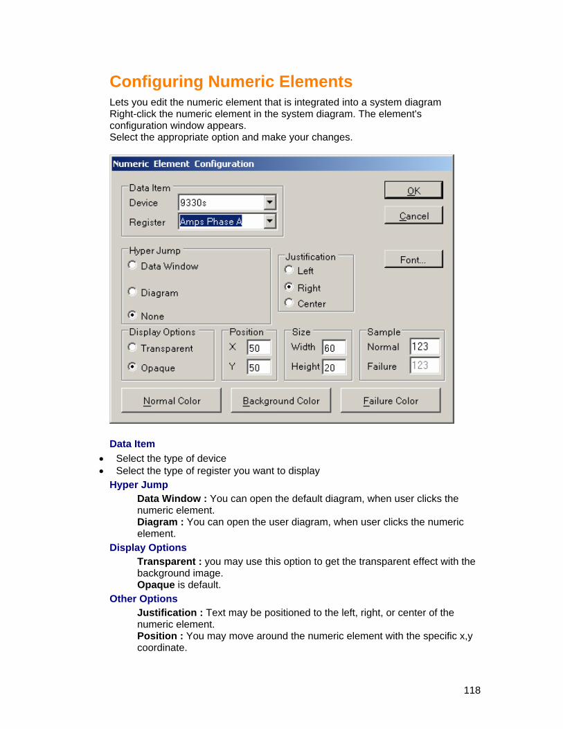
Configuring Numeric Elements
w appears.
Lets you edit the numeric element that is integrated into a system diagramRight-click the numeric element in the system diagram. The element's configuration windoSelect the appropriate option and make your changes.
Data
• Sele• Select the type of register you want to display
Data Window : You can open the default diagram, when user clicks the numeric element. Diagram : You can open the user diagram, when user clicks the numeric element.
Display Options Transparent : you may use this option to get the transparent effect with the background image. Opaque is default.
Other Options Justification : Text may be positioned to the left, right, or center of the numeric element. Position : You may move around the numeric element with the specific x,y coordinate.
Item ct the type of device
Hyper Jump
118

Size : You may edit width or height of the nnumeric value.
umeric element with the specific
mal, i.e.
r of the numeric element. Font : Click the font button to change the text properties.
Click OK to save your changes to the numeric element.
Normal color : Choose the color, when the numeric element is norcommunicating properly. Failure color : Choose the color, when the numeric element is abnormal, i.e. Not communicating. Background color : Choose the background colo
119

ConLets you edit the analog element that is integrated into a system diagram
he element's configuration
Select the appropriate option and make your changes.
figuring Analog Elements
Right-click the analog element in the system diagram. Twindow appears.
Data Item
• Select the type of device • Select the type of register you want to display
Hyper Jump Data Window : You can open the default diagram, when user clicks the analog element. Diagram : You can open the user diagram, when user clicks the analog element.
Label Dial : If the checkbox is unchecked, it will hide the dial marks in the gauge element. Name : If the checkbox is unchecked, it will hide the name of the register that is displaying below the gauge.
Other Options Position : You may move around the analog element with the specific x,y coordinate. Size : You may edit width or height of the analog element with the specific value. Range : You may change the possible minimum or maximum range of a
120

analog gauge element. Min/Max - Drag Hands : If the checkbox is checked, the analog gauge will
evice display two drag hands indicate the minimum and maximum values dregister since the last reset.
Click OK to save your changes to the analog element.
121

Configuring Alarm Element
Lets you edit the alarm element that is integrated into a system diagram Right-click the alarm element in the system diagram. The element's cowindow appears.
nfiguration
Select the appropriate option and make your changes.
Alarm
• SeleH e
the default diagram, when user clicks the
Image choose the image to show when the alarm is active. Click
to get the image from your local computer or
cked. rowse Inactive' button to get the image from your local computer
server. Other
e around the alarm element with the specific x,y
ct the existing configured alarm yp r Jump
Data Window : You can openalarm element. Diagram : You can open the user diagram, when user clicks the alarm
ement. el Active : You maythe 'Browse Active' buttonserver. Inactive : You may choose the image to show when the alarm is inactive, This can achieved only when the 'Transparent when Inactive' is uncheClick the 'Bor Options Position : You may mov
122

coordinate. Size : You may edit width or height of the alarm image with the specific
Click ur changes to the alarm element.
value.
OK to save yo
123

Configuring Trip Unit Element
Lets you edit the trip unit element that is integrated into a system diagram Right-click the trip unit element in the system diagram. The element's cwindow appears.
onfiguration
Select the appropriate option and make your changes.
• Sele• Select the type of registe
Hypeindow : You can open the default diagram, when user clicks the trip
cks the trip unit element.
Other Options Symbol : You may change the symbol from breaker to square and vice versa. Orientation : You may rotate the breaker in 90 degree anticlockwise, if you click 'Horizontal'. Position : You may move around the trip unit element with the specific x,y coordinate. Size : You may edit width or height of the trip unit element with the specific value.
Click OK to save your changes to the trip unit element.
Data Item ct the type of device.
r you want to display. r Jump
ta WDaunit element. Diagram : You can open the user diagram, when user cli
124
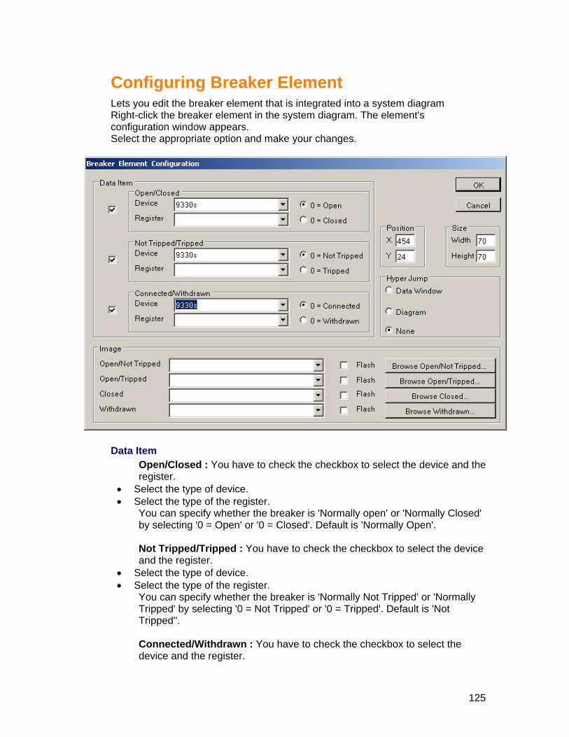
Configuring Breaker Element
w appears.
Lets you edit the breaker element that is integrated into a system diagramRight-click the breaker element in the system diagram. The element's configuration windoSelect the appropriate option and make your changes.
Data Item
Open/Closed : You have to check the checkbox to select the device and the register.
• Select the type of device. • Select the type of the register.
You can specify whether the breaker is 'Normally open' or 'Normally Closed' by selecting '0 = Open' or '0 = Closed'. Default is 'Normally Open'. Not Tripped/Tripped : You have to check the checkbox to select the device and the register.
• Select the type of device. • Select the type of the register.
You can specify whether the breaker is 'Normally Not Tripped' or 'Normally Tripped' by selecting '0 = Not Tripped' or '0 = Tripped'. Default is 'Not Tripped''. Connected/Withdrawn : You have to check the checkbox to select the device and the register.
125

• Select the type of device. • Select the type of the register.
You can specify whether the breaker is 'Normally Connected' or Normally
Data Window : You can open the default diagram, when user clicks the breaker element. Diagram : You can open the user diagram, when user clicks the breaker element.
Image Open/Not Tripped : You can select the image from the dropdown box. Click the 'Browse Open/Not Tripped' button to choose the image from your local computer or server. If you want to animate the image file, check the 'Flash' checkbox. Open/Tripped : You can select the image from the dropdown box. Click the 'Browse Open/Tripped' button to choose the image from your local computer or server. If you want to animate the image file, check the 'Flash' checkbox. Closed : You can select the image from the dropdown box. Click the 'Browse Closed' button to choose the image from your local computer or server. If you want to animate the image file, check the 'Flash' checkbox. Withdrawn : You can select the image from the dropdown box. Click the 'Browse Withdrawn' button to choose the image from your local computer or server. If you want to animate the image file, check the 'Flash' checkbox.
Withdrawn' by selecting '0 = Connected' or '0 = Withdrawn'. Default is 'Connected'.
Hyper Jump
Notes:Supported images are bmp, jpg, gif.
ther Options ion : You may move around the breaker element with the specific x,y
dth or height of the breaker element with the specific
Click
OPositcoordinate. Size : You may edit wivalue.
OK to save your changes to the breaker element.
126
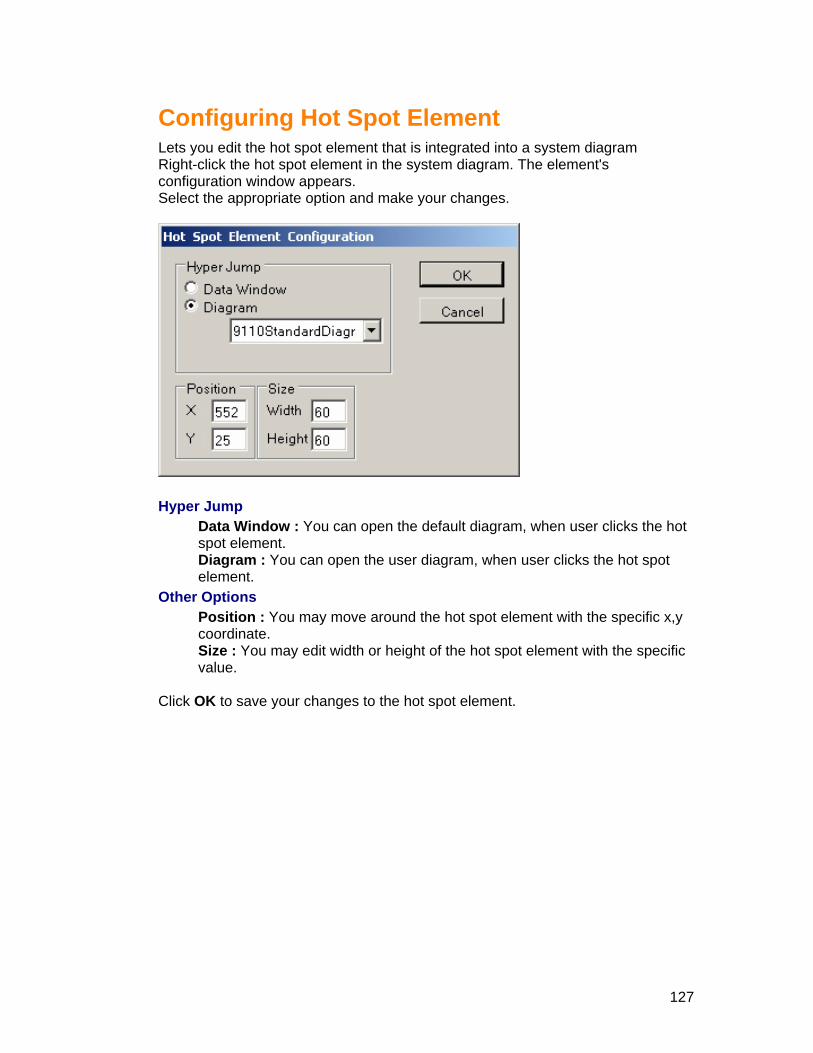
Configuring Hot Spot Element
m
w appears.
Lets you edit the hot spot element that is integrated into a system diagraRight-click the hot spot element in the system diagram. The element's configuration windoSelect the appropriate option and make your changes.
Hype
ow : You can open the default diagram, when user clicks the hot
the user diagram, when user clicks the hot spot
Otherou may move around the hot spot element with the specific x,y
ou may edit width or height of the hot spot element with the specific
Click OK to save your changes to the hot spot element.
r Jump Data Windspot element. Diagram : You can openelement. Options Position : Ycoordinate. Size : Yvalue.
127

Configuring Output Element
uration Lets you edit the output element that is integrated into a system diagram Right-click the output element in the system diagram. The element's configwindow appears. Select the appropriate option and make your changes.
Data Item
• Select the type of device. • Select the type of register.
Pulse the output Every time user clicks the button, it pulses the output. This works only, if you have checked the 'Pulse the Output' checkbox. You can change the value of ON and OFF.
Acknowledgement Pop-up : It will Pop-up a message window, when user clicks the output element. Password : It will ask you to type the user password, when user clicks the output element.
Other Options Button Label : You can change the text for the button output element. Position : You may move around the output element with the specific x,y coordinate. Size : You may edit width or height of the output element.
Click OK to save your changes to the output element.
128

Configuring Binary Element
figuration
lect the appropriate option and make your changes.
Lets you edit the binary element that is integrated into a system diagram Right-click the binary element in the system diagram. The element's conwindow appears. Se
Data Item
Select the type of device. • •
binary element.
s a binary element like Round,
e shape. If you want to
ate. the binary element with the specific
Click
Select the type of register. Hyper Jump
Data Window : You can open the default diagram, when user clicks the
Diagram : You can open the user diagram, when user clicks the binary element.
Other OptionShape : You can choose the shape ofRectangle, Diagonal / or Diagonal \. Colors : You can choose On and Off color for thanimate the shape, check the 'Flash' checkbox.
n : You may move around the binary element with the specific x,y PositiocoordinSize : You may edit width or height of value.
OK to save your changes to the binary element.
129

Configuring Sum Element
Lets yRight- sum element in the system diagram. The element's configuration windoSelec iate option and make your changes.
ou edit the sum element that is integrated into a system diagram click thew appears. t the appropr
Data Item
• Select the type of device. • Select the type of register that you want to be summed. • Click the 'Add' button to add the register in the Summed Items list box for
summing the values of the register. Notes: You can also remove the registers from the Summed Items. Select
the registers from the 'Summed Items', Click the 'Remove' button. Hyper Jump
Data Window : You can open the default diagram, when user clicks the sum element. Diagram : You can open the user diagram, when user clicks the sum element.
Display Options Transparent : you may use this option to get the transparent effect with the background image. Opaque is default.
Other Options Justification : Text may be positioned to the left, right, or center of the sum element. Font : Click the font button to change the text properties. Position : You may move around the sum element with the specific x,y coordinate. Size : You may edit width or height of the sum element with the specific value.
Click OK to save your changes to the sum element.
130

Configuring Device Icon
Lets you edit the Device Icon element that is integrated into a system diagramRight-clic
k the Device Icon element in the system diagram. The element's
make your changes. configuration window appears. Select the appropriate option and
Device Type
• Select the type of device for displaying the Image of the device. For example, if you select the 9200 Meter as a device type, it will display the 9200 meter picture in the system diagram.
Hyper Jump Data Window : You can open the default diagram, when user clicks the Device Icon element. Diagram : You can open the user diagram, when user clicks the Device Icon element.
Other Options Position : You may move around the Device Icon element with the specific x, y coordinate. Size : You may edit width or height of the Device Icon element with the specific value.
ick OK to save your changes to the Device Icon element. Cl
131

Boolean Element
Lets you e Right-clickconfig Boole r Boolean registers. bination of these re
dit the Boolean element that is integrated into a system diagram the Boolean element in the system diagram. The element's n window appears. uratio
an Elements are flexible tools that allow you to logically link togethean then initiate an action based on the condition of a comYou c
gisters.
UT Boolean element.
o determine what values mpare, i.e. the registers.
The nperfor g the vawe are going to use OR gate, the re
sing the Element he following steps outline how to use an AND/OR
The first step in using an AND/OR Boolean element is tyou wish to co
ext step is to determine what kind of evaluation you want the function to m. For example, Create the Data Item1 register Phase A is not exceedinlue 240 OR Data Item 2 register Phase B is not exceeding the value 220. As
sult will be true if any one of the condition is true.
Notes: Check the 'Enable' button to define the Data Item 2 and Data Item 3. You hoose only three logical conditions in each Boolean element. can c
Data • Select the type of device, type of register. • Sele
e AND/OR operator for the logical evaluation.
Data • Sele• Sele fine the value.
Hype
Item 1
ct the logical operator and define the value.
Select thItem 2 ct the type of device, type of register. ct the logical operator and der Jump Data Window: You can open the default diagram, when user clicks the Boolean element. Diagram: You can open the user diagram, when user clicks the Boolean
132
element. Options Other
ve around the Boolean element with the specific x, y
the specific value.
Colors True: Choose the right color to display the output when the condition is true. If you want to animate the output, check the 'Flash' checkbox. False: Choose the right color to display the output when the condition is false. If you want to animate the output, check the 'Flash' checkbox.
Click OK to save your changes to the Boolean element.
Display: Choose the right image to display the output of the evaluated values. Position: You may mocoordinate. Size: You may edit width or height of the Boolean element with
133

Muti-State Boolean Element
em
i-state Boolean element in the system diagram. The element's
Multi-state Boolean Elements are flexible tools that allow you to logically link together Boolean registers. You can then initiate an action based on the condition of a combination of these registers.
Lets you edit the Multi-state Boolean element that is integrated into a systdiagram Right-click the Multconfiguration window appears.
ment The fo . The fiwhat values you wish to compare, i.e. the registers. The next step is to determine
d of evaluation you want the function to perform.
For ex
Using the Elellowing steps outline how to use an AND/OR Multi-state Boolean element
rst step in using an AND/OR Multi-state boolean element is to determine
what kin
ample,
Binary 1
134

Data Item 1 Device 1 Phase A is not exceeding the value 240
2 Device 1 Phase B is not exceeding the value 220
ta Item 3 Device 1 Phase C is not exceeding the value 230 D
Data Item 1 Device 2 Phase A is not exceeding the value 240 AND Data Item 2 Device 2 Phase B is not exceeding the value 220 AND Data Item 3 Device 2 Phase C is not exceeding the value 230
In the above example,
Binary 1 data items are evaluated by logical operator OR, the result will be true if any one of the condition is true. Binary 2 data items are evaluated by logical operator AND, the result will be true only if any one condition is true. Binary 1 and Binary 2 are evaluated by logical operator AND, the result will be true only if any one condition is true.
OR Data ItemOR Da
ANBinary 2
Notes: Check the 'Enable' button to define more than 1 data item in each binary. You can choose maximum 6 logical conditions in each boolean element. i.e. for every binary output you can have 3 logical conditions. Data Items
• Select the type of device, type of register. • Select the logical operator and define the value.
Select the AND/OR operator for the logical evaluation. Hyper Jump
Data Window : You can open the default diagram, when user clicks the Multi-state Boolean element. Diagram : You can open the user diagram, when user clicks the Multi-state Boolean element.
Other Options Shape : Choose the right shape to display the output of the evaluated values. Position : You may move around the Multi-state Boolean element with the specific x, y coordinate. Size : You may edit width or height of the Multi-state Boolean element with the specific value.
Colors 0 / 0 : Choose the right color to display the output when the condition of Binary 1 is false and Binary 2 is false. If you want to animate the output, check the 'Flash' checkbox. 0 / 1 : Choose the right color to display the output when the condition of Binary 1 is false and Binary 2 is true. If you want to animate the output, check the 'Flash' checkbox. 1 / 0 : Choose the right color to display the output when the condition of
135

Binary 1 is true andcheck the 'Flash' che
Binary 2 is false. If you want to animate the output, ckbox.
on of
n element.
1 / 1 : Choose the right color to display the output when the conditiBinary 1 is true and Binary 2 is true. If you want to animate the output, checkthe 'Flash' checkbox.
lick OK to save your changes to the Multi-state BooleaC
136

Image Element
Lets you edit the Image element that is integrated into a system diagram Right-click the Image element in the system diagram. The element's configurwindow appears.
ation
Select the appropriate option and make your changes.
Device Type
• Select the type of device • Select the type of register you want to display
Hyper Jump Data Window : You can open the default diagram, when user clicks the Image element. Diagram : You can open the user diagram, when user clicks the Image element.
Image Filename : Choose the image from the drop down list or you can upload the local images into the drop down list. You may display the image as background or you may display the image when the register is true
137

Other Options Position : You may move around the Image element with the specific x, y coordinate. Size : You may edit width or height of the Image element with the specific value.
lick OK to save your changes to the Image element. C
138
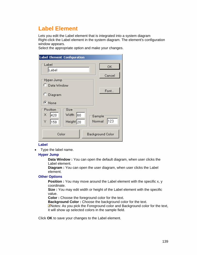
Label Element
Lets you edit the Label element that is integrated into a system diagramRight-click the Label element in the system diagram. The element's configurationwindow appears. Select the appropriate option and make your changes.
Label
• Type the label name. Hyper Jump
Data Window : You can open the default diagram, when user clicks the Label element. Diagram : You can open the user diagram, when user clicks the Label element.
Other Options Position : You may move around the Label element with the specific x, y coordinate. Size : You may edit width or height of the Label element with the specific value. Color : Choose the foreground color for the text. Background Color : Choose the background color for the text.
Notes: As you pick the Foreground color and Background color for the text, it will show up selected colors in the sample field.
Click OK to save your changes to the Label element.
139

Device Name Element
t is integrated into a system diagram system diagram. The element's
Lets you edit the Device Name element thaRight-click the Device Name element in the configuration window appears. Select the appropriate option and make your changes.
Data Item
• Choose the device for to display the name of the device. Hyper Jump
Data Window : You can open the default diagram, when user clicks the Device Name element. Diagram : You can open the user diagram, when user clicks the Device Name element.
Other Options Position : You may move around the Device Name element with the specific x, y coordinate. Size : You may edit width or height of the Device Name element with the specific value. Text Color : Choose the foreground color for the text. Background Color : Choose the background color for the text.
Notes: As you pick the Foreground color and Background color for the text, it will show up selected colors in the sample field. Font : Click the font tab to choose the font.
Click OK to save your changes to the Device Name element.
140
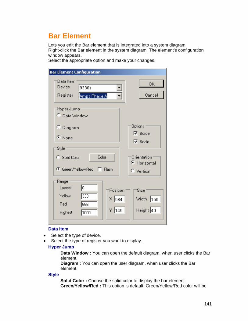
Bar Element
Lets you edit the Bar element that is integrated into a system diagram Bar element in the system diagram. The element's configuration Right-click the
window appears. Select the appropriate option and make your changes.
Data Item
• Sele• Sele
pe
Style Sol e solid color to display the bar element. Gre This option is default. Green/Yellow/Red color will be
ct the type of device. ct the type of register you want to display.
Hy r Jump Data Window : You can open the default diagram, when user clicks the Bar element. Diagram : You can open the user diagram, when user clicks the Bar element.
id Color : Choose then/Yellow/Red :
141

disp ment according to the range you define. If you want to animate the bar element, check the 'Flash' checkbox.
Range Low um value of the bar element. Hig the maximum value of the bar element.
layed in the bar ele
est : Typest : Type
the minimhe
Notes: Bar element will be displayed in green cololowe
r with respect to the
Yell he selected register is reaching the given numeric value, the bar element will be displayed in yellow color from lowest value to the current register value. Rest of the bar element value will be dRed e selected register is reaching the given numeric value, the bar element will be displayed in red color from lowest value to the current register value. Rest of the bar element value will be displayed in green color.
ther Op
entation : Choose to display the bar element in horizontal or vertical. Options : Check the 'Border' to display the border around bar element.
Click
st and highest value. e the numeric value. If tow : Typ
isplayed in green color. e the numeric value. If th : Typ
O tions Position : You may move around the Bar element with the specific x, y coordinate. Size : You may edit width or height of the Bar element with the specific value. Ori
Check the 'Scale' to display the scale of values.
OK to save your changes to the Bar element.
142
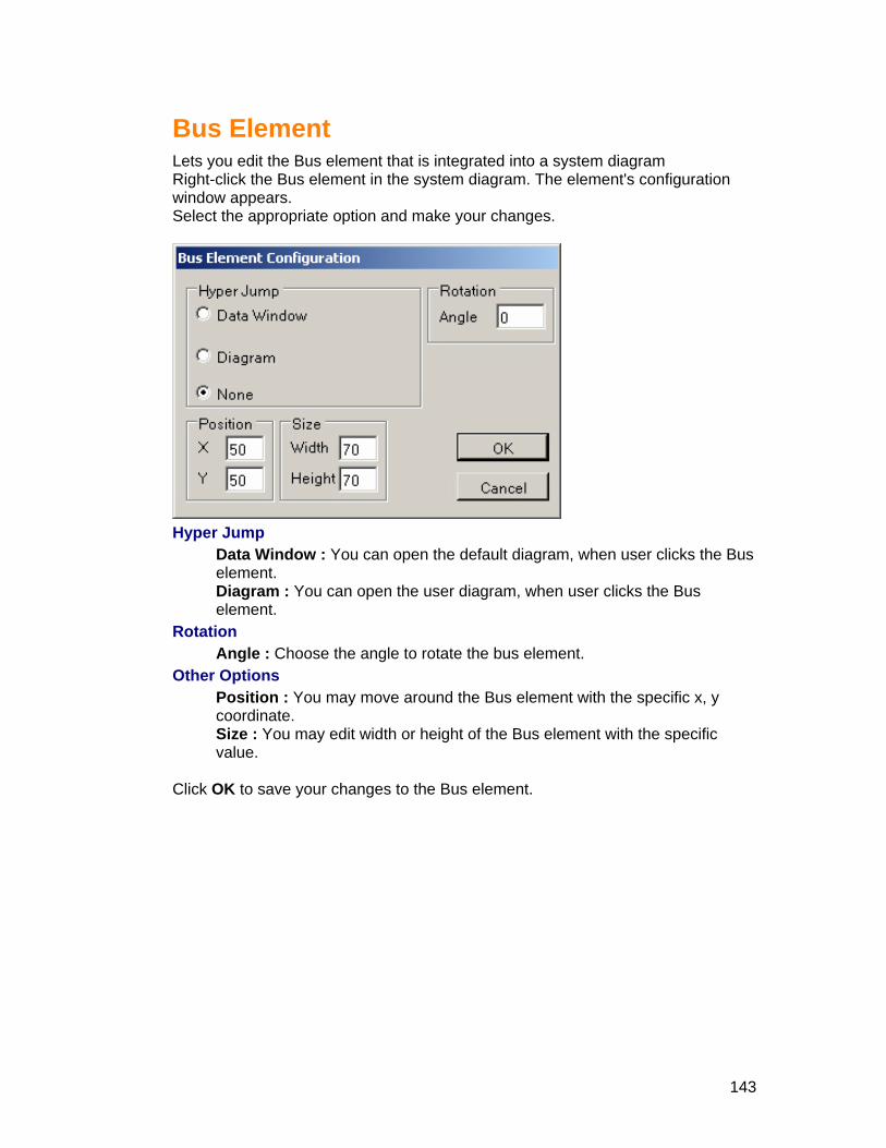
Bus Element
ts you edit the Bus element that is integrated into a system diagram ght-click the Bus element in the system diagram. The element's configuration ndow appears. lect the appropriate option and make your changes.
LeRiwiSe
Hyper Jump
Data Window : You can open the default diagram, when user clicks the Bus element. Diagram : You can open the user diagram, when user clicks the Bus element.
Rotation Angle : Choose the angle to rotate the bus element.
Other Options Position : You may move around the Bus element with the specific x, y coordinate. Size : You may edit width or height of the Bus element with the specific value.
Click OK to save your changes to the Bus element.
143

Setup Modbus Maps
different device communications drivers. Modbus devices are supported with the other devices are, OR using Modbus template
files w e. A Modbus template file for AEM is an XML file with the file extension .xml. In order to add a new Modbus device driver to an AEM system, you need only add the appropriate file to the Modbus subdirectory in your AEM installation directory. There is enough information in the file to tell AEM which Modbus devices to list in the Add Device page and to communicate to those devices, even configure the devices and present data on customized Standard Diagram pages. Custom Modbus template devices can be used with COM port or Ethernet connectivity.
Modbus Maps Overview
Access Energy Manager software supports many communication protocols and
hard-coded device drivers ashich can be created and added to the system at any tim
144

Add Modbus Map
is procedure describes how to add registers to Modbus Map. Procedure
1. Click the Setup tab from the left Menu tabs. 2. Click the Configuration tab. You will find all the setups below the configuration
tab. 3. Click the Setup Modbus.
Result: Setup ModbusMaps window will be displayed.
Th
4. Click the Add ModbusMap button Result: The Modbus RegisterMap Notepad window will be displayed.
5. Enter values in the fields with respect to your need. Read the following topics.
Modbus Register Map Name : Name of the device type (e.g. 'Square-D Enercept'). Note that this name is appended to generate the name of certain custom pages that may be associated with this device type. Spaces and punctuation marks "[ ; / ? " " @ & = + $ ] are converted to '_' when generating those names. For instance the Standard Diagram for the Square-D enercept is named as StandardDiagram_SquareD_Enercept.aspx.
Register ID : Modbus register valid numbers are usually 10001......49999, but any 16-bit unsigned data value can be used.
Register Name : You can type any name, which is meaningful to you. (e.g. "Amps Phase A").
145
Register Category : Register category, select from the dropdown list
REG_UNDEF tegory)
G_PROT_SET
VEFORM
hort ype)
le 2-byte
Modbus register 40001, then MBREGCOUNT would be the default of 0. If for instance, this register represents two 2-byte Modbus registers (40001 and 40002) comprising a 4-byte data value, then MBREGCOUNT would be 1.
ReadFn : The Modbus read command (generally a 3 or a 4 command is used to read). Default is 3. It's not included for most REGs. Valid values for ReadFn are usually 1, 3 or 4 but any value from 0 to 16 can be used.
WriteFn : The Modbus write command. Default is 16. It's not included for most REGs Valid values for WriteFn are usually 5, 6, 15 or 16 but any value from 0 to 16 can be used.
Enums : Click the Enums link to specify enums. Scale : Any single precision float is valid. Default is 1.0 DefRTReg : If this option is 'true', the register will be displayed in the Realtime data window. DefMin/Max : If this option is 'true', the register will be displayed in the Min/Max window. DefRTTrend : If this option is 'true', the register will be displayed in the Realtime data trending window. Note, you can choose only 4 registers are 'true'. For instance, if you choose more than 4 registers, it will display only
REG_REALTIME (Most common caREG_COMMAND REG_CONFIG REREG_LOG REG_MINMAX REG_WAREG_NA
Data Type : Select from the dropdown list. Char (Very common data type) UChar Short USInt (Most common data tUInt String Float Double TBitField
MBREGCOUNT : For instance, if this register represents a sing
146

the first four registers. DefSnapshot : If this option is 'true', the register will be displayed in the
6. dNewEntry button to add new register.
Snapshot window.
Click the Ad
147

EnumList Procedure
p tab from the left Menu tabs. 2. Click the Configuration tab. You will find all the setups below the configuration
3.w will be displayed.
1. Click the Setu
tab. Click the Setup Modbus.
Result: Setup ModbusMaps windo
Click the4. Add ModbusMap button ow will be displayed. Result: The Modbus RegisterMap Notepad wind
5. Click the 'Enums' link. It will display Enum List window.
VALUE : The numerical integer value that corresponds to the STRING (e.g. 1) Valid values range from 0…65535
owing VALUE (e.g. “Input STRING : The string that corresponds to the follOn”)
148

MASK : Numerical value to AND with the data before comparing to VALUFor instance you can MASK with 1, 2, 4
E. , 8 to get individual bit flags (e.g. 7
s with a mask of 7, for the 8 possible values). Valid MASK values
6. Click Save EnumList button to save the Enum List.
would mask the low 3 bits and you would typically expect eight ENUM sectionrange from 1…65535
149

Del
vent Logs
Logs. P cT
left Menu tabs.
4. C
ete AEM Event Logs
Deleting AEM EThis procedure describes how to delete AEM Event
ro edure o delete AEM Event Logs
1. Login to AEM. 2. Click the Setup tab from the3. Click the Configuration tab. You will find all the setups below the
configuration tab. lick the Delete AEM Event Logs
Result: The Setup AEM Event Log window is displayed.
5. From the Select Log Type drop-down list, select the Log Type name to d ll to delete all the event logs
6. Fr n list, select the Entry Type name to
te the selected event logs.
elete all the logs related to that type or select Aom the Select Entry Type drop-dow
delete all the logs related to that type or select All to delete all the entry typeevent logs.
7. Click Delete AEM Event Log to dele
150

Del
evices that were previously used in the system.
delete AEM Historical Devices
1. Lo2. C
iguration tab. 4. C
Result: The Delete Historical Devices window is displayed.
eting Historical Devices This procedure describes how to delete AEM Historical Devices. Historical Devices are dProcedure To
gin to AEM. lick the Setup tab from the left Menu tabs.
3. Click the Configuration tab. You will find all the setups below the conf
lick the Delete Historical Devices link.
5. From the list select Delete link on any device that need to be deleted permanently from the system
151

Ad
Setup Users
Settin
new user, you need to assign the person a user ID, User name, and Description. Passw ay need to assign the person a security level that determines which AEM features and commands the person will be able to access.
ministration
Setting Up User ID and Password
g Up User ID and Password This procedure describes how to set up new users in AEM. When you set up a
ord will be generated randomly for you. You m
Notes: If you want to change the Password, click here Procedure To set up a user in AEM:
1. Login AEM using a user ID that has a security setting that allows Setup User capabilities.
to
Notes: AEM is shipped to you with a default user already set up. The user
Use is displayed:
ID is Siemens. To learn how to log into AEM, click here. 2. From the Setup tab menu, click the Administration Tab, then click the Setup
rs. Result: The Setup Users window
3. Click the Add New User button. Result: The Add User window is displayed.
152

4. In the field, enter the name of the user. r ID for the user. This is the ID that they
6. The pass
ation. Description field
. From Select Base Gro own menu, select the base group that you wed to
9. To customize the User Security Scheck (or uncheck) the boxes n commands.
User Name5. In the User ID field, enter a unique use
will use, when they login. field Password will be generated randomly for you. You may change the word using Modifying User Password.
7. In the Description field, you may enter your title or designis optional.
8 the up drop-dThis deterwant to assign to the user.
see. mines which devices this user is allo
ettings that you assigned the user, manually ex to the listed AEM features and t
Notes: You can add or r ands from user
10p the user and returns you to the Setup Users window.
emove specific features and commaccess by manually chec
. Click the Save button. Result: AEM adds u
k or uncheck the boxes.
153

Changing User Access
ge user access in AEM. When changing
description.
p. •
1.
This procedure describes how to chanuser access, you can . . .
• Change the User Name and• Change the Base GrouChange the User Security Settings assigned to users
Procedure To change user access in AEM: Login to AEM using a user ID that has been enabled to Setup Users.
Notes: AEM is shipped to you with a user ID already set up. The user ID is Siemens. To learn how to log into AEM, click here
2. he Administration Tab, then click the Setup From the Setup tab menu, click tUsers.
Result: The Setup Users window is displayed
3. From the S er has a modify link. Click to ch
etup User window, You will find a column for Modify User. Each uson the 'Modify' link for the user whose settings you want
ange. Result: The Modify User window is displayed.
Notes: User ID cannot be changed hange the user's Name, enter the new user name in the User Nam4. To c e field.
5. To changefield. Description field
6. up, Select the new Base Group from the Select Base
7. the boxes mands.
the Description field, enter the new description in the Description is optional.
To change the Base GroGroup drop-down menu.
To change the User Security Settings, manually check (or uncheck) next to the listed AEM features and com
Notes: You can add or remove specific features and commands from user boxes.
9. Click M saves your changes and returns you to the Setup Users
access by checking or uncheck the the Save button.
Result: AEwindow.
154

Modifying Users Password
This procedure describes how to change User Password in AEM. Procedure To change users Password in AEM:
1. Login to AEM using a user ID that has edit capabilities for Setup User. Notes: AEM is shipped to you with a user ID already set up. The user ID
is Siemens. To learn how to log into AEM, click here 2. From the Setup tab menu, click the Administration Tab, then click the Setup
Users. Result: The Setup Users window is displayed
3. From the Setup User window, You will find a column for Password. Each user has a Password link. Click on the 'Password' link to the user whose settings you want to change.
Result: The Modify Password window is displayed.
4. To change the user’s password, enter the new password in the Password field. 5. Click Save button to save the new Password.
155

Removing Users
This procedure describes how to remove user from AEM.
1 capabilit
Procedure o change user accessT
to AEM:
. AEM using a user ID that Setup Users Login to ies. Notes: AEM is sh e er ID alre y
learn h lick here 2 n c n Tab, th
Setup U ayed
ipp d to you with a usow to log into AEM, c
lick the A
ad set up. The user ID is Siemens. To
From the Setup t. ab meUsers.
Result: The
u, dministratio en click the Setup
sers window is displ
3. From the Setup Ususer has a r
er window, you will find a column for Remove User. Each emove link. Click on the Remove link for the u
Result: The Remove User window is displayed wit l4. the User from AEM, Click the Remove User bu
moves the user that you have wanted to remove and returns you to the Setup Users window.
ser to be deleted. h a l fields disabled.
To Remove tton. Result: AEM re
156

Setting up Contacts
ser Contact s how to set up new contact details in AEM. These contact
gure an alarm or a report and send a a pager or a FAX machine.
ntact details
1. tab from the left Menu tabs.
tup Contacts layed.
Setting up UThis procedure describedetails will be useful when you confinotification to a user's email ID or to Procedure To set up a co
Login to AEM. 2. Click the Setup3. Click the Administration Tab, then click the Se
tup Contacts window is dispResult: The Se
4. lds in the contact form. Fill in all the fieNotes: Although all fields are optional, you m
st four fields. These first four fields tust enter something in at least
ogether make a contact
5.
If...
one of the firunique.
Click the Save Profile button to save the contact details.
Then... you want to add another contact. • Click the Add New Contact
button. • Fill in all the fields in the form. • Click the Save Profile button.
y
lds in the contact form.
Click the Add New Contact button. ou want to reset all the fie
you want to close the contact form window.
Click the Close button.
157

you want to modify the existing contact
• Select the contact person from the Select Contact drop-down list.
the necessary fields in the
changes you made, or Remove to delete
• Change form.
Click the Save Profile button for the
the contact.
158

Setup
Preferences
Preferences Settings
Groups Data Polling Rate Groups Data polling rattG ta
Alarms polling rate is how often AEM browser client polls for the data from the APoMail Server Address (SMTP) Y a or D
e is how often AEM browser client polls for the data from he AEM Server and shows it in the Group Summary screen. You may change the
oups Data Polling Rate to see the output difference in Viewing Summary DarAlarms Display Polling Rate
EM Server and shows it in the Status bar. You may change the Alarms Display lling Rate to see the difference in Alarm Tracker Status bar.
ou may have to enter the SMTP (Simple Mail Transfer Protocol) mail serverddress to configure AEM with your mail server for sending alarms through email
scheduled report notification through email. You may type the IP Address or main Name of your mail server. o
Notes: IP Address: If you are connecting to the internet, your ISP must have provided your server's IP address, and the default gateway's IP address. (The default gateway is the ISP computer through which your computer routes all Internet traffic.)
Notes: You may contact your network administrator for any help on
e in the Mail Server address field for the browser to contact your mail Server. For example 'siemens.com'
this. Domain Name System (DNS): On the Internet, Web sites usually use the Domain Name System. If you register a domain name for your site, users can type your site's domain nam
Notes: You may contact your network administrator for any help on
e describes how to set up a Polling rates and the Server
ure
1.2. Setup
this. Preferences Settings This procedurConfiguration for the above scenarios. ProcedTo modify a setting in AEM Preferences: Login to AEM. From the Setup tab menu, click the Administration Tab, then click the
159

Preferences. Result: The Preferences window is displayed.
You may change the desired Polling rates for real time, Standard diagram, 3.
4.5.
Groups data, Alarms Display. Enter the Mail Server Address for AEM to contact you through email.
on for modified data to be saved. Click the Save butt
160

Display Below is a list of the most common Display tasks you will perform in Access Energy Manager. Select any help topic for more information.
Lists Groups Reports Project List
• Viewing Project List Connection List
• Viewing Connection List
• Resetting Connections
Device List
• Viewing Device List Default Alarm List
• lt Viewing DefauAlarm List
Alarm List
• Viewing Alarm List Data Log List
• Log Viewing Data List
Exported DataLogs
• Download Exported DataLogs
• Remove Exported DataLogs
Realtime Trends List
• Viewing Realtime Trends List
AEM EventLogs List
• Viewing EventLogs List
Scheduled Jobs List
• Viewing Scheduled Jobs List
Groups • Viewing Groups • Viewing Standard
Diagram • Viewing Realtime Data • Viewing Realtime
Trending • Configuring Device
Configuration • Clear Settings • Viewing Summary Data
Billing Report • Create Manual Report
• By Devices • By Group
• Create Scheduled Report • By Devices • By Group
• Modifying Billing Report
• Removing Billing Report
• Run Billing Report Load Analysis Report
• Create Manual Report • By Devices • By Group
• Create Scheduled Report • By Devices • By Group
• Modifying Load Analysis Report
• Removing Load Analysis Report
• Run Load Analysis Report
View Existing Reports
• View Billing Reports View Load Analysis Report
161

Lists
Pro
ibes about displaying the Project List in AEM.
ject List
Viewing Project ListThis help topic descrProcedure To view a Project List, perform the following procedure:
1. Login to AEM b from the left Menu tabs. 2. Click the Display ta
3. Click the Lists tab. 4. Click the Project List
Result: Project List window will be displayed with the existing Projects Notes: To Sort by fields in the table, click the column heading. For ample, if you want to sort by Project Title, then click the column heading oject Title.
exPr
Project Title It shows Name of the Project that is meaningful to you and the other people who
ase Name
shows the date on which the project was created. Default Project
e t is open or ing True or Fals
work with your electrical system. DatabIt shows the name of the database.
ate Created DIt
Default project will show thclose by show
status of the project, whether the projece
Notes: To set Default Project, click here
Topics •
Related
How to Setup Projects
162

Connection List
Connection List, perform the following procedure:
1.2. Click 3. Click e Lists tab. 4. Click e Connection List
st window will be displayed with the existing nnections.
Viewing Connection ListThis help topic describes about available Connection List in AEM. Procedure To view a Login to AEM
e Display tab from the left menu tabs. ththth
Result: Connection LiCo
Notes: To Sort by fields in the table, click the column heading. For sort by connection name, then click the column
heading Connection Name.
example, if you want to
Connection Name It shows the name of the connection that is meaningful to you and the other people who work with your electrical system. Connection Type Type is a protocol and physical connectivity combination. AEM currently supports 5 types of connections which is described below.
• SEABUS/COM SEABUS/COM connection is a connection from a COM port on a AEM computer
to electrical devices that communicate using SEABUS protocol. The SEABUS devices can be connected to the COM port by one of the following
methods:
• Directly (RS-232) • Via an Isolated Multi-Drop Converter (RS-485) • Via some type of modem, such as dial-up, short range, radio, or fiber
optic To allow AEM to monitor and control SEAbus devices connected to a COM port
on your computer, add a SEAbus/COM connection to your AEM system.
163

• SEABUS/E
thernet Converter
SEABUS/Ethernet Converter connection is a network connection from a AEM onnected to the network through an Ethernet
M to monitor and control SEABUS devices connected to your net Converter
ction is a connection from a COM port on a AEM computer
The me
• Directly (RS-232)
port .
•
BUS/Ethernet Converter connection is a network connection from a AEM t
MODBUS devices connected to your network through an Ethernet Converter, add a MODBUS/Ethernet Converter
• Wireless/File
US/Ethernet Conve connection from a AEM computer to MODBUS devices connected to the network through an Ethernet
your
e rter to your AEM system.
It shows the COM port # on your computer to which the physical connection is he particular connection.
computer to SEABUS devices cConverter.
To allow AE
network through an Ethernet Converter, add a SEABUS/EtherConnection to your AEM system.
• MODBUS/COM
MODBUS/COM conne
to electrical devices that communicate using MODBUS protocol. MODBUS devices can be connected to a COM port by one of the following
ods: th
• Via an Isolated Multi-Drop Converter (RS-485) • Via some type of modem, such as dial-up, short range, radio, or
fiber optic To allow AEM to monitor and control MODBUS devices connected to a COM
on your computer, add a MODBUS/COM connection to your AEM system MODBUS/Ethernet Converter MOD
computer to MODBUS devices connected to the network through an EtherneConverter.
To allow AEM to monitor and control
Connection to your AEM
system.
MODB rter connection is a network
Converter.
To allow AEM to monitor anetwork through an EthConnection
nd control MODBUS devices connected to rnet Converter, add a MODBUS/Ethernet Conve
COM Port
made to tSimulation
164

It shows whether the connection is in demo mode or realtime.
ss
shows the total number of data packets requested from all devices on the nnection since the last reset.
Speed It shows the Baud Rate at which the devices are communicated. IP AddreIt shows the Ethernet connection is connected through this IP Address.
otal Packets TIt co
Notes: A data packet is a set of data bytes from a device. The type of data cluded in a packet depend on the device being polled. otal Responses
It shows the number of times AEM got responses for the requests that were made.
inT
Notes: No responses The number of times AEM requested a data packet from a device but did not receive a response. Some reasons for no response include.
• A device lost power • A network connection was lost • Baud rate of the device and the AEM connection port don’t match • The device address assigned to a device does not match the address set
up for that device in AEM • Improper communication wiring
Notes: No responses occur occasionally even under the best
circumstances. A small percentage of no responses relative to the total number of packets requested (1 percent or less) is probably not a problem.
Total errors It shows the number of data errors that AEM has detected.
Notes: Data errors occur when AEM receives a data packet that contains errors. They occur occasionally even under the best circumstances. A small percentage of data errors relative to the total number of packets requested (1 percent or less) is probably not a problem. A greater percentage may indicate a problem with the COM port or the Baud rate settings. Reset Status Click on this help topic: How to Reset the Polling Counters Related Topics
• How to Setup Connections
165
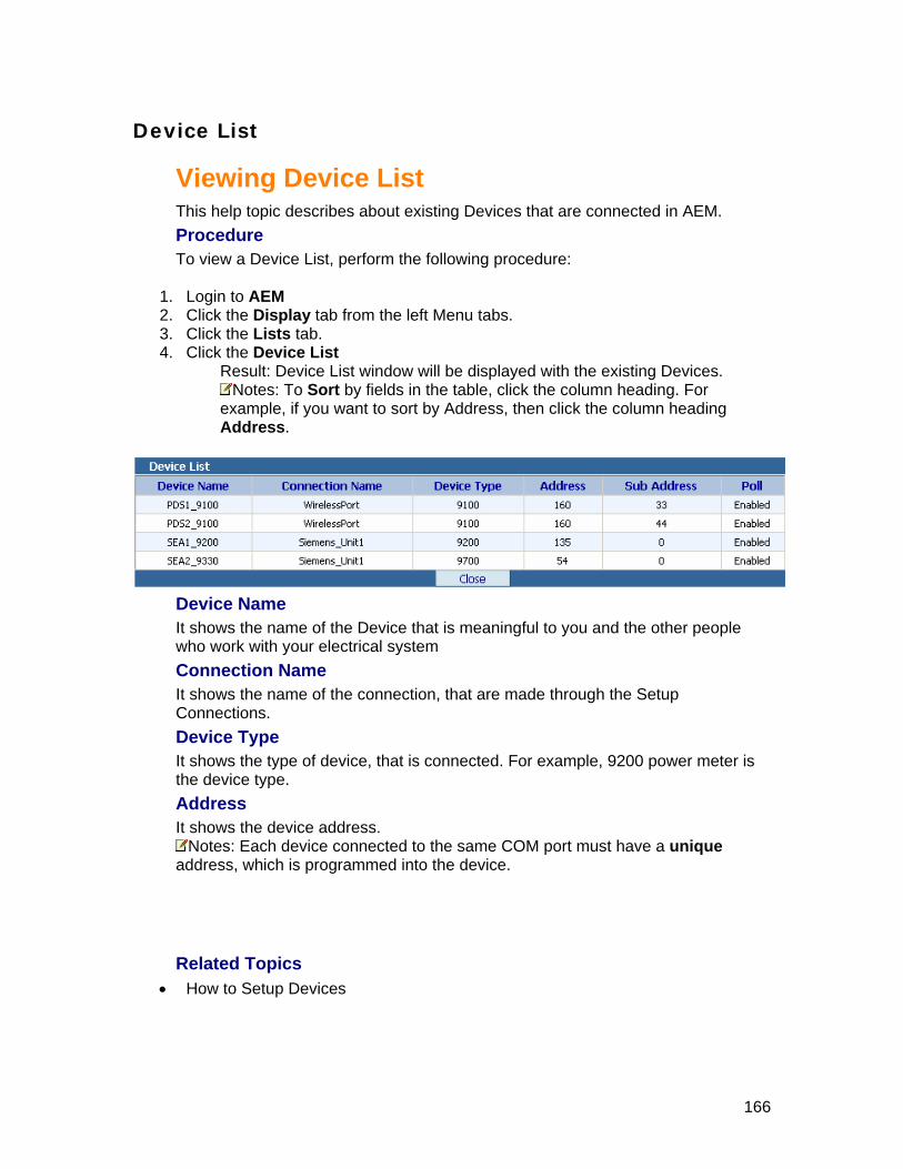
Device List
Viewing Device List This help topic describes about existing Devices that are connected in AEM. Procedure To view a Device List, perform the following procedure:
1. Login to AEM 2. Click the Display tab from the left Menu tabs. 3. Click the Lists tab. 4. Click the Device List
Result: Device List window will be displayed with the existing Devices. Notes: To Sort by fields in the table, click the column heading. For ample, if you want to sort by Address, then click the column heading
Address. ex
Device Name
ul to you and the other people
tion Name h the Setup
is connected. For example, 9200 power meter is type.
the device address.
It shows the name of the Device that is meaningfwho work with your electrical system ConnecIt shows the name of the connection, that are made througConnections. Device Type It shows the type of device, that the device Address It shows
Notes: Each device connected to the same COM poraddress, which is programmed into the device.
t must have a unique
Related Topics •
How to Setup Devices
166
Default
VieThis p scribes how to change the attributes of a Alarms that is already set up
view a Default Alarm List, perform the following procedure:
from the left Menu tabs.
4. Clicksult: Default Alarm List window will be displayed with the existing default
alarms configured.
Alarm List
wing Default Alarm List rocedure de in your AEM:
Procedure To
1. Login to AEM 2. Click the Display tab3. Click the Lists tab.
the Default Alarm List Re
Notes: To Sort by fields in the table, click the column heading. For example, if you want to sort by Register, then click the column heading Register.
evice Type Shows the type of device associated with a default alarm. For example, in the above picture, all Default Alarms are associated with the 9200 device type. Register Shows the name of the device register associated with a default alarm. Type Shows the value compare type of the Default alarm. The following table shows how the type works when the default alarm triggers.
If... Then...
D
the default alarm type is > (High Limit)
It checks the register value is greater than > the value that user inputs
the default alarm type is < (Low Limit)
It checks the register value is less than < the value that user inputs
167

the default alarm type is Change
It compares the register value changes from the value that user inputs.
the default alarm type is = (Equal to)
It compares the registerthe value that user input
value is equal to s.
the default alarm type is not to )
It compares the register value is Not equal to the value that user inputs. = (Not equal
Value ter compare value for the specific default alarm
if a Wav (Sound) file has been configured to be playeEmaIndicates if an email should be sent to a designated user when the alarm is triggered. X means email has been setup for this alarm.
Shows the regisWav Shows an indicator that specifies
d when an alarm is triggered. X means a WAV file should be played. il
168

Alar
Alarm List
dure:
3. Click4. Click
sult: Alarm List window will be displayed with the existing alarms configured.
m List
ViewingThis help topic describes the Alarm List display in AEM. Procedure To view a Alarm List, perform the following proce
1. Login to AEM 2. Click the Display tab from the left Menu tabs.
the Lists tab. he Alarm List t
Re
Notes: To Sort by fields in the table, click the column heading. For example, if you want to sort by Value, then click the column heading Value.
evice Type ows the type of device associated with a default alarm. For example, in the
above picture, all Default Alarms are associated with the 9200 device type. Register Shows the name of the device register associated with a default alarm. Type Shows the value compare type of the Default alarm. The following table shows how the type works when the default alarm triggers.
If... Then...
DSh
the alarm type is > (High Limit)
It checks the register value is greater than > the value that user inputs
the alarm type is < (Low Limit)
It checks the register value is less than < the value that user inputs
the alarm type is Change
It compares the register value changes from the value that user inputs.
169

the alarm type is = (Equal to) the value that user input
It compares the register value is equal to s.
the alarm type is not = (Not equal to)
It compares the register value is equal to the value that u
Not ser inputs.
Value gister compare value for the specific default alarm
tor that specifies if a Wav (Sound) file has been configured to be AV file should be played.
trigge
Shows the reWav Shows an indicaplayed when an alarm is triggered. X means a WEmail Indicates if an email should be sent to a designated user when the alarm is
red. X means email has been setup for this alarm.
170

Active Alarm List
List
ure:
ist
a
Viewing Active Alarm This help topic describes the Active Alarm List display in AEM. Procedure To view a Active Alarm List, perform the following proced
1. Login to AEM 2. Click the Display tab from the left Menu tabs. 3. Click the Lists tab. 4. Click the Active Alarm L
Result: Active Alarm List window will be displayed with the existing active larms.
Notes: • To Sort by fields in the table, click the column heading. For example, if you want
to sort by Value, then click the column heading Value. • To Filter Results by Device, select the device name in the drop-down list for
filtering the results by device. • To alarm, click on the Alarm Image to remove the particular alarm. • ve All the alarm, click Delete All button to remove all the active alarm
nd time stamp, when the active alarm was triggered.
of the Device associated with the alarm.
ows the device type of the device associated with the alarm. For example, 9200 wer meter is the device type.
er that is associated with the active alarm. Value Shows the current register value for the active alarm.
Remove To Remolist.
DateTime Shows the date aDevice Shows the name Device Type ShpoRegister Shows the name of the device regist
171

Data Log List
Viewing Data log List This procedure describes how to view a data log in AEM. You can view any dalog by performing this procedure.
ta
Shows the name of the Data log. al
pturing data for the data log.
device register list for the data log. ProcTo vie
1. Logi2. Click from the left Menu tabs. 3. Click e Lists tab. 4. Click the Data log List
Result: Data Log List window will be displayed with the existing Data logs
Data Log Name
Log IntervShows the time interval (in seconds) for caRegisters Shows the first item in the
edure w a data log, perform the following procedure:
n to AEM he Display tab t
th
the View link to the respective data logs that you want 5. Click to view.
Result: The Data log Viewer window will be displayed with a Graphs and select device register options.
6. -Register Combinations to be graphed from the Select Device Select the DeviceRegister List
Notes: Use Shift key and/or Ctrl key for selecting more than one register from the list.
7. After selecting the Device-Registers, Click the Refresh Graph button Result: Graph is displayed with new Device-Registers combinations that you have selected now.
8. Click the Close button for exiting from the Data Log Viewer.
172

Exported DataLogs
Download Exported DataLogs
r
:
existing ported datalogs.
This procedure describes how to download an exported datalog from AEM ServeComputer. Procedure To download an exported datalog, perform the following procedure
1. Login to AEM 2. Click the Display tab from the left Menu tabs. 3. Click the Lists tab. 4. Click the Exported DataLogs
Result: Exported DataLogs window will be displayed with theex
5. Click the Download link to the respective datalog that you want to download. Result: The data log will be exported as an Excel file. You may save the Data logs in excel format for your reference.
173

Remove Exported DataLogs
datalog in AEM.
1. M 2.3.
rted DataLogs displayed with the existing
This procedure describes how to remove a exportedProcedure To remove a exported datalog, perform the following procedure: Login to AE Click the Display tab from the left Menu tabs.
Click the Lists tab. 4. Click the Expo
Result: Exported DataLogs window will begs. exported datalo
5. Click the Remove link to the respective datalog that you want to remove. Result: The exported datalog will be removed immediately without any warning.
174

Realtime Trends List
ime Trends List nnected in
Procedure g procedure:
4. Clickwindow will be displayed with the existing
R
Viewing RealtThis help topic describes about existing Realtime Trends List that are coAEM.
To view a Realtime Trends List, perform the followin
1. Login to AEM 2. Click the Display tab from the left Menu tabs. 3. Click the Lists tab.
the Realtime Trends List Result: Realtime Trends List
ealtime Trends Configured. Notes: To Sort by fields in the table, click the column heading. For
example, if you want to sort by trend name, then click the column heading Trend Name.
5. Click the View link to the respective Realtime Trends that you want to view. Result: Realtime Trending will display in the Realtime Trending Display window.
175
Diagram List
Viewing Diagram List This help topic describes about existing Diagrams that are setup in AEM.
ocedure
4. Click.
PrTo view Diagram List, perform the following procedure:
1. Login to AEM om the left Menu tabs. 2. Click the Display tab fr
3. Click the Lists tab. the Diagram List Result: Diagram List window will be displayed with the existing Diagrams
Notes: To Sort bye
fields in the table, click the column heading. For xample, if you want to sort by Diagram, then click the column heading
Diagram.
Diagram It shows the name of the Diagram that is meaningful to you and the other people who work with your electrical system Date Created It shows the date on which the diagram is created. Last Modified It shows the date on which the diagram was modified.
•
Related Topics
How to Setup Diagrams
176

Mo
VieThis h Modbus Maps that are setup in AEM.
To vie
1. Login to AEM 2. Click the Display tab from the left Menu tabs. 3. Click e Lists tab.
bus
dbus Map List
wing Modbus Map List elp topic describes about existing
Procedure w Modbus Map List, perform the following procedure:
th4. Click the Modbus Maps List
Result: Modbus Maps List window will be displayed with the existing ModMaps.
Notes: To Sort by fields in the table, click the column heading. For xample, if you want to sort be y Modbus Map, then click the column heading
Modbus Map.
Modbus Map It shows the name of the Modbus Map that is meaningful to you and the other people who work with your electrical system Date Created It shows the date on which the Modbus map is created. Last Modified It shows the date on which the Modbus map was modified. Related Topics
• How to Setup Modbus Map
177

AEM EventLogs List
Viewing AEM EventLogs List This help topic describes about existing AEM EventLogs List that are logged in
M database.
ventLogs List, perform the following procedure:
3. Click4. Click
window will be displayed.
AEProcedure To view a AEM E
1. Login to AEM 2. Click the Display tab from the left Menu tabs.
the Lists tab. the AEM EventLogs List
Logs SelectionResult: AEM Event
5. Select Start Date and Stop Date from the drop-down list. 6. Select Start Time and Stop Time from the drop-down list. 7. In the Select Log Type drop-down list, select the designated Log Type events. 8. Click Get AEM Event Log button
Result: Event Logs list will display in the AEM Event Logs Viewer window. Notes:
• To Sort by fields in the table, click the column heading. For example, if you want to sort by log type, then click the column heading Log Type.
• You may filter the Event logs by selecting the Error type in the Filter Results by Error Type drop-down list.
• You may press Next > to go next page of Event Log List or press <Previous to go previous page of Event Log List.
178

9. Click <<Back to go AEM EventLogs Selection window or Click Close button to EM Event Log Viewer.
close the A
179

Scheduled Jobs List
Viewing Scheduled Jobs List This help topic describes about existing Scheduled Jobs List that are connected in AEM. Procedure To view a Scheduled Jobs List, perform the following procedure:
1. Login to AEM 2. Click the Display tab from the left Menu tabs. 3. Click the Lists tab. 4. Click the Scheduled Jobs List
Result: Scheduled Jobs List window will be displayed with the existing Scheduled Jobs List.
180
Groups
Groups This picture shows the G in ACCESS Energy Manager.
Viewingroups Tree view
To view a group follows these steps:
n to AEM 2. Click the Display Tab from the Left Menu Bar. 3. Click the Groups t
Result: This w d to the roups in the same
1. Logi
ab. ill display any available Groups and devices adde
G window Notes: See the above diagram for example.
181

Viewing StandardThis picture shows how to view the Standard Diagram data for the devices in ACCESS Energy Mana
Diagram
ger.
To view the data Diagram follow these steps:
1. Login to AEM 2. Click the Display Tab from the Left Menu Bar. 3. Click the Groups t
Result: This will display
of a Standard
ab. any available Groups and devices in the tree view.
Notes: If you don'tgroup and add
Device n
have any groups and Devices you may create new oup devices to gr
ame 4. Click the Notes:
rate for thSee the ab e Standar
Result: The Standa isplayed with all the data in the Main Screen a
ove diagram for your reference. To change the Pollingd Diagram data, click here to Change Polling Raterd Diagram window is d
rea.
182

Viewing Realtime Data This picture shows how to get the Realtime values for the devices in ACCESS Energy Manager.
To view a Realtime Value follow these steps:
1. Login AEM 2. Click e Display Tab from the Left Menu Bar.
devices in the tree view.
to th
3. Click the Groups tab. Result: This will display any available groups and
Notes: If you don't have any groups and devices you may create a new group and add devices to group
4. Click e Device name thNotes: See the above diagram for your reference.
Result: The Device Features window is displayed with all the tabs.
5.ow is displayed with all the values in the
Main Screen area. To change the Polling rate for the Realtime Data, Click here to Change Polling Rate
Click the Realtime Data tab. Result: The Realtime Data wind
183

Notes: Click the Edit button to add/delete the registers from the Realtime Display.
184

Viewing Realtime Trending is picture shows how to get the Realtime Trending for the devices in ACCESS
Energy Manager. Th
To view the Realtime Trending follow these steps:
1. Login to AEM 2. Click the Display Tab from the Left Menu Bar. 3. Click the Groups tab.
Result: This will display any available Groups and devices in the tree view. Notes: If you don't have any groups and Devices you may create a ne
group and add devices to group Click the Device name
w
4. Notes: See the above diagram for you reference.
vice Features window is displayed with all the tabs. Result: The De
5. ic ding tab. Result: The Realtime Trending window is displayed with a graphical display of different register values, which is configured through Setup Realtime
ds.
Cl k the Realtime Tren
Tren
185

186

Configuring Device Configuration This picture shows how to setup the Device Configuration for the devices in
nager. ACCESS Energy Ma
To configure the Device Configuration follow these steps:
1. Login to AEM 2. Click the Display Tab from the Left Menu Bar. 3. Click the Groups tab.
Result: This will display any available Groups and devices in the tree view. Notes: If you don't have any groups and Devices you may create new
group and add devices to group 4. Click the Device name
Note: See the above diagram for you reference. Result: The Device Features window is displayed with all the tabs.
5. Click the Device Configuration tab. Result: The Device Configuration window is displayed with all the fields.
187

Note: Follow the table to feed the input in the respective fields.
In this field... Enter the following...
Basic Configuration Setup Volt Mode From the drop-down list, select which type of
connection the meter uses to measure voltage: • Demo • 3 Wire Wye • 4 Wire Wye • Single Phase • Delta • Delta Direct
Note: Select demo mode to configure the meter for a demonstration.
PT Primary Primary rating of the voltage transformers. Enter the Number between (1 to 65535)
PT Secondary Secondary rating of the voltage transformers. Enter the Number between (1 to 65535)
CT prim ry mers. a Primary rating of the current transforEnter the Number between (1 to 65535)
CTEnter the Number between (1 to 65535)
Secondary Secondary rating of the current transformers.
Va Polarity From the drop-down list, choose one of the following:
• Inverted Normal
188

Vb Polarity From the drop-down list, choose one of the following:
• Inverted Normal
Vc Polarity From the drop-down list, choose one of the following:
• Inverted Normal
Ia Polarity From the drop-down list, choose one of the following:
• Inverted Normal
Ib Polarity From the drop-down list, choose one of the
• Inverted Normal
following:
Ic P e following:
• Inverted
olarity From the drop-down list, choose one of th
Normal Demand Setup Demand Interval Length This value is measured in seconds. The default value is
900 seconds (15 minutes). Number of Per
Number of demand periods that you want the meter to Demand iods average to calculate demand (1 to 5).
Scaling Setup Volt Scale From the drop-down list, choose the Voltage
or example, 'x100' means, multiply the displayed value scale:
Fby 100 for the actual value. Default value is 'x10'
Amp S From the drop-down list, choose the Current
ns, multiply the displayed value
cale scale:
For example, 'x100' meaby 100 for the actual value. Default value is 'x10'
Amp N From the drop-down list, choose the Neutral current scale:
For example, 'x100' means, multiply the displayed value by 100 for the actual value. Default value is 'x10'
eutral Scale
Power Scale From the drop-down list, choose the Power scale: ed value
by 100 for the actual value. Default value is 'x10' For example, 'x100' means, multiply the display
Energy Pulsing Setup Digital Output #1 Time Constant
Enter the number of seconds (0.1 to 999.9) to set the pulse duration.
DigConst pulse duration.
ital Output #2 Time nt
Enter the number of seconds (0.1 to 999.9) to set the a
Digital Output Irda Enter the number of seconds (0.1 to 999.9) to set the pulse duration.
Digital Output #1 Output From the drop-down list, select the mode for Digital
189

Mode Output #1: • kWh Pulse • kVAh Pulse • kvarh Pulse • Ext 1
Ext 2 Digital Output #2 Output Mode
From the drop-down list, select the mode for Digital Output #2:
• kWh Pulse • kVAh Pulse • kvarh Pulse • Ext 1
Ext 2 Digital Output Irda Mode From the drop-down list, select the mode for Digital
Output Irda: • kWh Pulse • kVAh Pulse • kvarh Pulse • Ext 1
Ext 2 Communication Setup RTS Display Enter the number of milliseconds (0 to 1000) to set
the RTS Display. Default is :20
Display Setup Display Scroll Delay Enter the number of seconds (0 to 30) to set the
Display Scroll Delay. Default is :0
Display Refresh Time Enter the number of seconds (1 to 6) to set the
Default is :2 Display Refresh Time.
Password By default, the password is set to 0 (zero) in the factory. hanged to any number (0 to The password may be c
9999).
6. Click the Configure button. Result: You will get message saying that 'Device successfully configured. It
will take few seconds to reflect the change in all modules'.
190
Clear Settings This picture shows how to clear the settings for the devices in ACCESS Energy Manager.
To clear the settings follow these steps:
1. Login to AEM 2. Click the Display Tab from the Left Menu Bar. 3. Click the Groups tab.
sult: This will display any available Groups and devices in the tree view. ReNotes: If you don't have any groups and Devices you may create new
group and add devices to group 4. Click the Device name
Notes: See the above diagram for your reference. Result: The Device Features window is displayed with all the tabs.
5. Click the Clear Settings tab. sult: The Clear Settings window is displayed. Re
6. Click the buttons for clearing Reset Energy, Peak Energy Demand and Peak Amp Demand.
191

V
in a anager.
iewing Summary Data This picture shows how to view the Summary data of various devices that aregroup in ACCESS Energy M
To view a Summary Data follow these steps:
1. Login to AEM 2. Click the Display Tab from the Left Menu Bar. 3. Click the Groups tab.
Result: This will display any available Groups and devices in the tree view. Notes: If you don't have any groups and Devices you may Create new
group and add devices to group 4. Click the Group Name
Notes: See the above diagram for your reference. (Example. Here First Floor and Second Floor are two different Groups) Result: The Summary window is displayed with all the different summary data in the Main Screen area.
5. Click on each tab for the different Summary data.
Basic Summary
T are c n
vg - Cur Avg Power (kW) - kW total • Power Factor - PF Total
his shows the Basic Summary of following registers for the devices thaton ected to the same group.
• Voltage LL Avg - Volt LL • Current A•
192

Currents
This shows the Current Summary of following registers for the devices that are connected to the same group. • Current A - Cur Ph A • Current B - Cur Ph B • Current C - Cur Ph C • Current Average - Cur Avg
Demand Currents
• Demand Current A - Ia Demand Demand Current B - Ib Demand
and Current B - Ib Peak Demand • Peak Demand Current C - Ic Peak Demand
This shows the Demand Current Summary of following registers for the devices that are connected to the same group.
•• Demand Current C - Ic Demand • Peak Demand Current A - Ia Peak Demand • Peak Dem
Voltages
e devices that are connected to the same group.
lt BC V CA - Volt CA • V – AN - Volt Ph A • V – BN - Volt Ph B • V – CN - Volt Ph C
This shows the Line to Line Voltage Summary of following registers for th
• V AB - Volt AB • V BC - Vo•
193
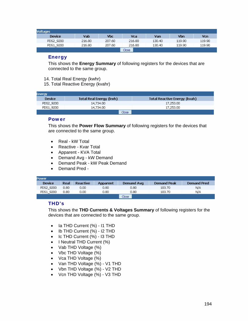
Energy
This shows the Energy Summary of following registers for the devices that are connected to the same group.
14. Total Real Energy (kwhr) 15. Total Reactive Energy (kvahr)
Power
This shows the Power Flow Summary of following registers for the devices that are connected to the same group. • Real - kW Total • Reactive - Kvar Total
• Apparent - KVA Total • Demand Avg - kW Demand • Demand Peak - kW Peak Demand • Demand Pred -
T
connected to the same group.
• Ia THD Current (%) - I1 THD • Ib THD Current (%) - I2 THD • Ic THD Current (%) - I3 THD • I Neutral THD Current (%) • Vab THD Voltage (%) • Vbc THD Voltage (%) • Vca THD Voltage (%) • Van THD Voltage (%) - V1 THD • Vbn THD Voltage (%) - V2 THD • Vcn THD Voltage (%) - V3 THD
HD's
This shows the THD Currents & Voltages Summary of following registers for the evices that ared
194

195

Reports
Bi Create Manual Report
• By Devices • By Group
• Create Scheduled Report • By Devices • By Group
• Modifying Billing Report • Removing Billing Report • Run Billing Report
lling Report •
196

Cr
Creating Manual Billing Report by Devices
This c evices in
create a Manual Billing Report by Devices:
1. Login to AEM. 2. Click the Display Tab from the Left Menu Tabs. 3. Click the Reports button. 4. Click the Create Billing Report
Result: Billing Reports window will be displayed in the Main Screen area.
eate Manual Report
pro edure describes how to create a Manual Billing Report by DACCESS Energy Manager.
rocedure PTo
Notes: If there is no report created, you will get the message saying that 'No reports found, Please use the Add Report button to add your first report'.
5. Click the Add Report button. This will launch the Billing Report Configuration wizard.
Notes: Enter the Billing Report name in the Report Name field. • Select a method for reports to run manually. • Select a method for select devices individually.
6. Click the Next >button to go the next step, or click the < Previous button to back up one step.
•
197

7. Select a Start Date and Time for the Billing Report Cycle to start. Notes: If you want to use Calendar for your reference, You may click the
Show Calendar button. 8. Select a Stop Date and Time for the Billing Report Cycle to end.
Notes: If you want to reset the Start and Stop Time, you may click the Clear Times button. This will reset the times.
9. Click the Next >button to go the next step, or click the < Previous button to back
up one step.
10. Select devices from Available Devices for inclusion in the report, then click the button to add to the Add Selected Devices.
Notes: • You might use Add All button to add all the devices from Available Devices to
• You might use Remove button to remove the devices from Selected Devices to
• ght use Remove All rom Selected
Selected Devices.
Available Devices. You mi button to remove all the devices fDevices to Available Devices.
198

11. Click the Next >button to go the next step, or click the < Previous button to back up o
ne step.
12. Specify the Time of Use category, Day, Start Time, Stop Time Notes: See the Legend and Tips for you reference.
13. Click the Update TOU Schedule button for changes to be shown on the diagram.
Notes: Click the Set to Defaults button to clear all the values. 14. Click the Next >button to go the next step, or click the < Previous button to back
up one step.
199

15. Check Holidays according to your company's holidays for the year. Notes:
• By default we have checked all the common holidays in the United States • If Your company holiday is not listed under United States and Canada. You can
customize the holiday name and respective date using User Defined Dates. 1. Specify name in the Date name field. 2. Specify the date in the Date field 3. Click Add button to add the User Defined Holidays.
• If you added wrong holiday information mistakenly, you may want to delete it by selecting the name from the list box and click the Delete button
16. ic ious button to back
Cl k the Next >button to go the next step, or click the < Prevup one step.
200

17. Type the tariffs in dollars for the report calculation. Notes: The following settings are optional.
• d Monthly Fixed Cost per device and a description for the fixed costs.
• You may add Tax Rate to add taxes to the utility bill. 18. Click the Save button.
Result : Billing Report Configuration window is displayed with the message saying "Saving Billing Report Configuration...". then it goes to Billing Reports window with the added report in the Main Screen area.
You may ad
Notes: To run the Billing Report, click here
201

Creating Manual Billing Report by Group
This procedure describes how to create a Manual Billing Report by Group in ACCESS Energy Manager. Procedure To create a Manual Billing Report by Group:
1. Login to AEM. 2. Click the Display Tab from the Left Menu Tabs. 3. Click the Reports button. 4. Click the Create Billing Report
Result: Billing Reports window will be displayed in the Main Screen area. Notes: If there is no report created, you will get the message saying that
'No reports found, Please use the Add Report button to add your first report'.
5. Click the Add Report button. This will launch the Billing Report Configuration wizard.
Notes: • Enter the Billing Report name in the field. Report Name• Select a method for reports to run manually. • Select a method for selecting devices by group.
6. Click the Next >button to go the next step, or click the < Previous button to back up one step.
202
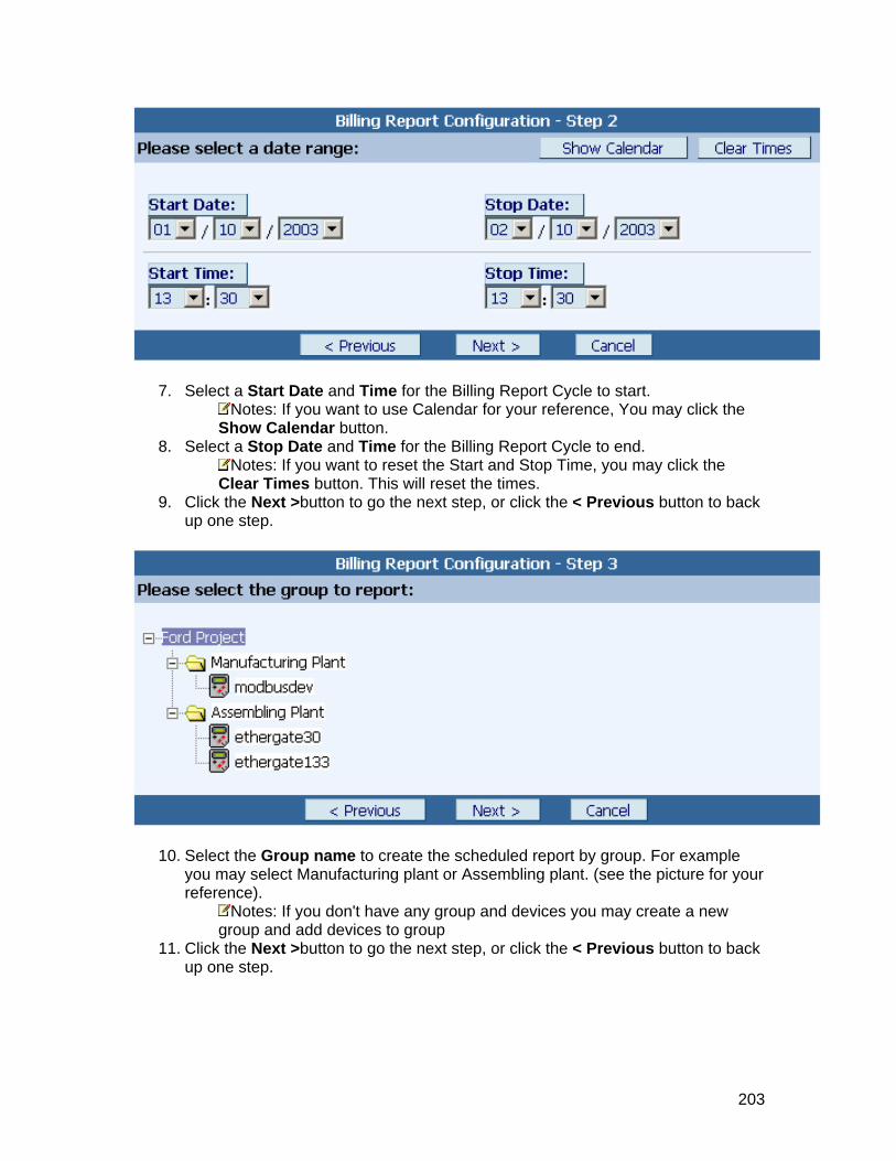
7. Select a Start Date and Time for the Billing Report Cycle to start. Notes: If you want to use Calendar for your reference, You may click the
Show Calendar button. 8. Select a Stop Date and Time for the Billing Report Cycle to end.
Notes: If you want to reset the Start and Stop Time, you may click the Clear Times button. This will reset the times.
9. Click the Next >button to go the next step, or click the < Previous button to back up one step.
10. Select the Group name to create the scheduled report by group. For example you may select Manufacturing plant or Assembling plant. (see the picture for your reference).
Notes: If you don't have any group and devices you may create a new group and add devices to group
11. Click the Next >button to go the next step, or click the < Previous button to back up one step.
203
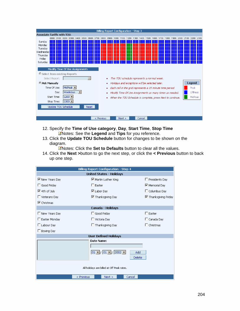
. Specify the Time of Use category, Day, Start Time, Stop Time 12
Notes: See the13. Click the Update TOU
diagram.
L S n on the egend and Tips for you reference. chedule button for changes to be show
Notes: Click th14. Click the Next >
e Sbutton to go the next step, or click the < Previous button to back
et to Defaults button to clear all the values.
up one step.
204

15. Check Holidays according to your company's holidays for the year.
Notes: By default we have checked all the common holidays in the United States If Your company
• • holiday is not listed under United States and Canada. You can
holiday name and respective date using User Defined Dates. e name field.
Specify the date in the Date field tton to add the User Defined Holidays.
y want to delete it by e list box and click the Delete button
ext step, or click the < Previous button to back up o
customize the1. Specify name in the Dat2. 3. Click Add bu
• If you added wrong holiday information mistakenly, you maselecting the name from th
16. Click the Next >button to go the nne step.
17. Type the tariffs in dollars for the report calculation. Notes: The following settings are optional.
• You may add Monthly Fixed Cost per device and a description for the fixed costs.
• You may add Tax Rate to add taxes to the utility bill. 18. Click the Save button.
Result : Billing Report Configuration window is displayed with the message saying "Saving Billing Report Configuration...". then it goes to Billing Reports window with the added report in the Main Screen area.
Notes: To run the Billing Report, click here
205
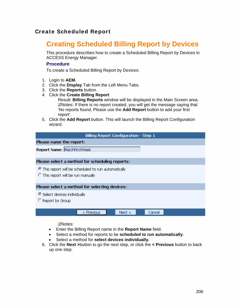
Create Scheduled Report
es
describes how to create a Scheduled Billing Report by Devices in
duled Billing Report by Devices:
ft Menu Tabs. 3. Click4. Click e Create Billing Report
Result: Billing Reports window will be displayed in the Main Screen area.
Creating Scheduled Billing Report by DevicThis procedureACCESS Energy Manager.
rocedure PTo create a Sche
1. Login to AEM. 2. Click the Display Tab from the Le
the Reports button. th
Notes: If there is no report created, you will get the message saying that 'No reports found, Please use the Add Report button to add your first report'.
5. Click e Add Report button. This will launch the Billing Report Configuration
thwizard.
Notes: • Enter the Billing Report name in the Report Name field. • Select a method for reports to be scheduled to run automatically. • Select a method for select devices individually.
6. Click the Next >button to go the next step, or click the < Previous button to back up one step.
206

7. From the Start Time drop-down list, select a Start Time for the Billing Report Cycle to start.
8. From Run Frequency drop-down list, select a Run Frequency for the Billing Report Cycle to run the report.
9. From Select a report duration drop-down list, select a report duration for the period of time to use for the data in the report.
10. From the Optional E-mail notification drop-down list, select a contact person to notify through email after completing the scheduled report.
the
the
Notes: • Email notification is optional. • You have to check the checkbox to enable the Contact list.
11. Click the Next >button to go the next step, or click the < Previous button to back up one step.
10. Select devices from Available Devices for inclusion in the report, then click the Add button to add to the Selected Devices.
Notes: • You might use Add All button to add all the devices from Available Devices to
207

Selected Devices. • You might use Remove button to
Available Devices. remove the devices from Selected Devices to
• button to remove all the devices from Selected De Devices.
11. Clic n to go the next step, or click the < Previous button to back
You might use Remove Allvices to Availablek the Next >butto
up one step.
12. Specify the Time of Use category, Day, Start Time, Stop Time Notes: See the Legend and Tips for you reference.
13. Click the Update TOU Schedule button for changes to be shown on the diagram.
Notes: Click the Set to Defaults button to clear all the values. 14. Click the Next >button to go the next step, or click the < Previous button to back
up one step.
208
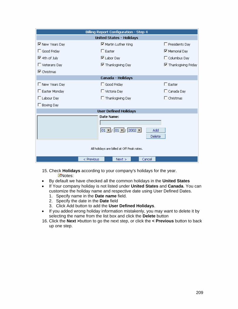
Check Holidays accor15. ding to your company's holidays for the year. Notes:
• By default we have checked all the common holidays in the United States • If Your company holiday is not listed under United States and Canada. You can
customize the holiday name and respective date using User Defined Dates.
s.
ame from the list box and click the Delete button 16. Click the Next >button to go the next step, or click the < Previous button to back
up one step.
1. Specify name in the Date name field. 2. Specify the date in the Date field 3. Click Add button to add the User Defined Holiday
• If you added wrong holiday information mistakenly, you may want to delete it by selecting the n
209

Type the tariffs in dollars17. for the report calculation. Notes: The following settings are optional.
You may add Monthly Fixed Co• st per device and a description for the fixed
• ay add Tax Rate to assess tax on the bill.
Scheduled Reports may also been seen in the Scheduled Jobs List
costs. You m
18. Click the Save button. Result: Billing Report Configuration window is displayed with the messagesaying "Saving Billing Report Configuration...".
210

Creating Scheduled Billing Report by Group
is procedure describes how to create a Scheduled Billing Report by Group in CESS Energy Manager.
rocedure create a Scheduled Billing Report by Group:
1. Login AEM. 2. Click the Display Tab from the Left Menu Tabs. 3. Click the Reports button. 4. Click the Create Billing Report
Result: Billing Reports window will be displayed in the Main Screen area.
ThACPTo
to
Notes: If there is no report created, you will get the message saying that 'No reports found, please use the Add Report button to add your first report'.
5. Click the Add Report button. This will launch the Billing Report Configuration wizard.
Notes: • Enter the Billing Report name in the Report Name field. • Select a method for reports to scheduled to run automatically. • Select a method for selecting devices by group that has one or more
devices. 6. Click the Next >button to go the next step, or click the < Previous button to back
up one step.
211
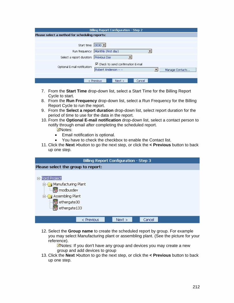
the Start Time drop-down list, select a Start Time for the Billing Report 7. From
Cycle to start. 8. From the Run Frequency drop-down list, select a Run Frequency for the Billing
Report Cycle to run the report. 9. From Select a report duration drop-down list, select report duration for the
period of time to use for the data in the report. 10. From the Optional E-mail notification drop-down list, select a contact person to
notify through email after completing the scheduled report.
the
Notes: • Email notification is optional.
11. to go the next step, or click the < Previous button to back
• You have to check the checkbox to enable the Contact list.
Click the Next >buttonup one step.
12. Select the Group name to create the scheduled report by group. For example you may select Manufacturing plant or assembling plant. (See the picture for your reference).
Notes: If you don't have any group and devices you may create a new group and add devices to group
13. Click the Next >button to go the next step, or click the < Previous button to back up one step.
212

14. Specify the Time of Use category, Day, Start Time, Stop Time Notes: See the L
15. Clickegend and Tips for you reference.
diag the Update TOU Schedule button for changes to be shown on the
ram. Notes: Click the Set to Defaults button to clear all the values.
16. Click e Next >button to go the next step, or click the < Previous button to back up one step.
th
213

17. Check Holidays according to your company's holidays for the year. Notes:
• By default we have checked all the common holidays in the United States • If your company holiday is not listed under United States and Canada. You can
customize the holiday name and respective date using User Defined Dates. 1. Specify name in the Date name field. 2. Specify the date in the Date field 3. Click Add button to add the User Defined Holidays.
• If you added wrong holiday information mistakenly, you may want to delete it by selecting the name from the list box and click the Delete button
18. Click the Next >button to go the next step, or click the < Previous button to back up one step.
214
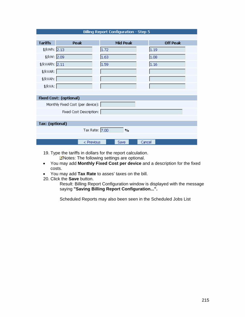
19. Type the tariffs in dollars for the report calculation. Notes: The following settings are optional.
• d Monthly Fixed Cost per device and a description for the fixed costs.
• You may add Tax Rate to asses’ taxes on the bill. 20. Click the Save button.
Result: Billing Report Configuration window is displayed with the message saying "Saving Billing Report Configuration...". Scheduled Reports may also been seen in the Scheduled Jobs List
You may ad
215

M
To mo
1. Login AEM. 2. Click the Display Tab from the Left Menu Tabs. 3. Click the Reports button. 4. Click the Create Billing Report
Result: Billing Reports window will be displayed in the Main Screen area. 5. Click the Modify link to the respective Billing Report that you want to edit. This
will launch the Billing Report Configuration wizard with all the existing data in it. 6. From this point on, the wizard is exactly like creating a new report, except that
the data and options already selected for this report will show up in the screens presented. the f
If... Then...
odifying Billing Report This procedure describes how to Modify a Billing Report in ACCESS Energy Manager. Procedure
dify a Billing Report.
to
Thus, you only need to modify those items you need to change. See ollowing table for your reference.
You want to modify Manual report by Devices
See Creating Manual Billing Report by Devices
You want to modify Manual report by Group
See Creating Manual Billing Report by Group
You want to modify Scheduled report by Devices
See Creating Scheduled Billing Report by Devices
You want to modify Scheduled report by Group
See Creating Scheduled Billing Report by Group
216

RemS
rea.
oving Billing Report This procedure describes how to Remove a existing Billing Report in ACCESEnergy Manager. ProcedureTo Remove a Billing Report.
1. Login to AEM. the Left Menu Tabs. 2. Click the Display Tab from
3. Click the Reports button. 4. Click the Create Billing Report
Result: Billing Reports window will be displayed in the Main Screen a
5. Click the Remove link to the respective Billing Report that you want to remove. Result: This will launch a message window saying that "Are you sure you
nt to remove this report?". o', then it
waIf you click 'Yes', then it will remove permanently, else if you click 'Ncancels the remove operation.
217
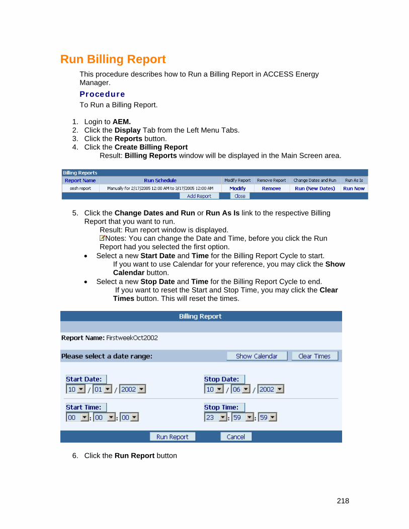
Run Billing Report
P
To Run a Billing Report.
2. he Left Menu Tabs. n.
4. Clickrea.
This procedure describes how to Run a Billing Report in ACCESS Energy Manager.
rocedure
1. Login to AEM. Click the Display Tab from t
3. Click the Reports butto the Create Billing Report Result: Billing Reports window will be displayed in the Main Screen a
5. Click the Change Dates and Run or Run As Is link to the respective Billing run.
Result: Run report window is displayed. Report that you want to
Notes: You can change the Date and Time, before you click the Run Report had you selected the first option.
Select a new Start Date and Time for the Billing Report Cycle to start. If you want to use Calendar for your reference, you may click the Show Calendar button.
• Select a new Stop Date and Time for the Billing Report Cycle to end. If you want to reset the Start and Stop Time, you may click the Clear Times button. This will reset the times.
•
6. Click the Run Report button
218

sult: The Billing Report is now being processed.
• •
hat to do next
Re• You may click Wait for results button to view a list of completed reports.
You may click Report Main Page button to configure or run another report. You may click Close button to leave reports.
W
View Billing R
ep
orts
219

Load Analysis Report • Create Manual Report
vices • By De• By Group
• ces
ort
• Create Scheduled Report By Devi• By Group
• is Report Modifying Load Analys• Removing Load Analysis Rep• Run Load Analysis Report
220

Create Manual Report
Creating Manual Load Analysis Report by
create a manual Load Analysis Report by SS Energy Manager.
alysis Report by Devices.
1. Logi2. Click ab from the Left Menu Tabs. 3. Click e Reports button. 4. Click the Create Load Analysis
Result: Load Analysis Reports window will be displayed in the Main Screen area.
Devices
This procedure describes how to Devices in ACCEProcedure To create a manual Load An
n to AEM. the Display Tth
Notes: If there is no report created, you will get the message saying that 'No reports found, Please use the Add Report button to add your first report'.
5. Click the
Add Report button. This will launch the Load Analysis Report Configuration wizard.
Notes: Report Name field. • Enter the Load Analysis Report name in the
221

• Select a method for reports to run manually. • Select a method for select devices individually.
6. Click e Next > button to go the next step, or click the < Previous button to back up o
thne step.
7. Select a Start Date and Time for the Load Analysis Report Cycle to start. Notes: If you want to use Calendar for your reference, You may click the
Show Calendar button. 8. Select a Stop Date and Time for the Load Analysis Report Cycle to end.
Notes: If you want to reset the Start and Stop Time, you may click the Clear Times button. This will reset the times.
9. Click the Next > button to go the next step, or click the < Previous button to back up one step.
10. Select devices from Available Devices for inclusion in the Report Generation, and then click the Add button to add in the Selected Devices.
222

Notes: • to
• e Remove button to remove the devices from Selected Devices to
• all the devices from Selected ilable Devices.
ious button to back up one
You might use Add All button to add all the devices from Available DevicesSelected Devices. You might usAvailable Devices. You might use Remove All button to removeDevices to Ava
11. Click the Save button to save, or click the < Prevstep.
12. Click the Save button. Result : Load Analysis Report Configuration window is displayed with the message saying "Saving Load Analysis Report Configuration...".
Then it goes to the Load Analysis Reports window with the added report in the Main Screen area.
Notes: To run the Load Analysis Report, click here
223

Creating Manual Load Analysis Report by Group This procedure describes how to create a manual Load Analysis Report by Group in ACCESS Energy Manager. Procedure To create a manual Load Analysis Report by Group.
1. Login to AEM. 2. Click the Display Tab from the Left Menu Tabs. 3. Click the Reports button. 4. Click the Create Load Analysis
sult: Load Analysis Reports window will be displayed in the Main ReScreen area.
Notes: If there is no report created, you will get the message saying that 'No reports found, please use the Add Report button to add your first report'.
5. Click Add Report button. This will launch the Load Analysis Report theConfiguration wizard.
Notes: • Report name in the Report Name field.
Select a method for reports to run manually. • Select a method for selecting devices by group.
6. Click the Next > button to go the next step, or click the < Previous button to back up one step.
Enter the Load Analysis •
224

7. Select a Start Date and Time for the Load Analysis Report Cycle to start. Notes: If you want to use Calendar for your reference, You may click the ow Calendar button.
8. Select a Stop Date and Time for the Load Analysis Report Cycle to end. Sh
Notes: If you want to reset the Start and Stop Time, you may click the
ck tep.
Clear Times button. This will reset the times. 9. Click the Next > button to go the next step, or click the < Previous button to ba
up one s
0 l by1 . group. For example Se ect the Group name to create the scheduled reportyou may select Manufacturing plant or Assembling plant. (see the picture for your reference).
Notes: If you don't have any group and devices you may create a new group and add devices to group
11. Click the Save button to save the Load Analysis Report, or click the < Previous button to back up one step.
12. Click the Save button. Result: Load Analysis Report Configuration window is displayed with the message saying "Saving Load Analysis Report Configuration...”
225

Then it goes to the Load Analysis Reports window with the added report in the Main Screen area.
Notes: To run the Load Analysis Report, click here
226
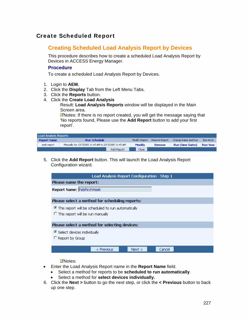
Create Scheduled Report
CreaThis procedDevices in ACCESS Energy Manager. Procedure To cre
1. Login to AEM. 2. Click the Display Tab from the Left Menu Tabs. 3. Click the Reports button. 4. Click the Create Load Analysis
Result: Load Analysis Reports window will be displayed in the Main Screen area.
ting Scheduled Load Analysis Report by Devices ure describes how to create a scheduled Load Analysis Report by
ate a scheduled Load Analysis Report by Devices.
Notes: If there is no report created, you will get the message saying that 'No reports found, Please use the Add Report button to add your first report'.
5. Click the Add Report button. This will launch the Load Analysis Report Configuration wizard.
Notes: • Enter the Load Analysis Report name in the Report Name field.
• Select a method for reports to be scheduled to run automatically. • Select a method for select devices individually.
6. Click the Next > button to go the next step, or click the < Previous button to back up one step.
227

the 7. From Start Time drop-down list, select a Start Time for the Load Analysis
Report Cycle to start.
9.
10. From drop-down list, select a contact person to notify through email after completing the scheduled report.
8. From the Run Frequency drop-down list, select a Run Frequency for the Load Analysis Report Cycle to run the report. From the Select a report duration drop-down list, select a report duration for theLoad Analysis Report data used in the report.
the Optional E-mail notification
Notes: • Email notification
ave to che t. t button to back
is optional. • You h
11. Click the Next >button
ck the checkbox to enable the Contact liso go the next step, or click the < Previous
up one step.
12. Select devices from Available Devices for inclusion in the Report Generation, and then click the Add button to add in the Selected Devices.
Notes: • You might use Add All button to add all the devices from Available Devices to
Selected Devices.
228

• You might use Remove button to remAvailable Devices.
ove the devices from Selected Devices to
•
13 tton to save, or click the < Previous button to back up one
14Result : Load Analysis Report Configuration window is displayed with the
aying "Saving Load Analysis Report Configuration...".
You might use Remove All button to remove all the devices from Selected Devices to Available Devices.
. Click the Save bustep.
. Click the Save button.
message s
Scheduled Reports may also been seen in the Scheduled Jobs List
229

Creating Scheduled Load Analysis Report by Group
Analysis Report by Devices.
This procedure describes how to create a manual Load Analysis Report by Devices in ACCESS Energy Manager. Procedure To create a manual Load
1. Login to AEM. 2. Click the Display Tab from the Left Menu Tabs. 3. Click the Reports button. 4. Click the Create Load Analysis
Result: Load Analysis Reports window will be displayed in the Main creen area. SNotes: If there is no report created, you will get the message saying that o reports found, please use the Add Report button to add your first 'N
report'.
5. Click theConfigur
Add Report button. This will launch the Load Analysis Report ation wizard.
Notes: • Enter the Load Analysis Report name in the Report Name field.
• Select a method for reports to be scheduled to run automatically. • Select a method for selecting devices by group that has one or more
devices. 6. Click the Next > button to go the next step, or click the < Previous button to back
up one step.
230
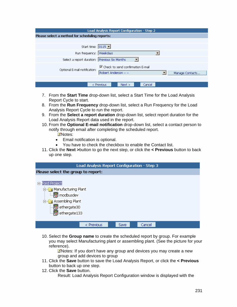
7. From the Start Time drop-down list, select a Start Time for the Load Analysis Report Cycle to start.
8. From the Run Frequency drop-down list, select a Run Frequency for the Load Analysis Report Cycle to run the report.
9. From the Select a report duration drop-down list, select report duration for the Load Analysis Report data used in the report.
10. From the Optional E-mail notification drop-down list, select a contact person to notify through email after completing the scheduled report.
Notes: • Email notification is optional. • You have to check the checkbox to enable the Contact list.
11. Click the Next >button to go the next step, or click the < Previous button to back up one step.
10. Select the Group name to create the scheduled report by group. For example you may select Manufacturing plant or assembling plant. (See the picture for your reference).
Notes: If you don't have any group and devices you may create a new group and add devices to group
11. Click the Save button to save the Load Analysis Report, or click the < Previous button to back up one step.
12. Click the Save button. Result: Load Analysis Report Configuration window is displayed with the
231

message saying "Saving Load Analysis Report Configuration...".
Scheduled Reports may also been seen in the Scheduled Jobs List
232

Modifying Load Analysis Report
nager.
Report.
This procedure describes how to Modify a Load Analysis Report in ACCESS Energy MaProcedure
To modify a Load Analysis
1. Login to AEM. 2. Click the Display Tab from the Left Menu Tabs. 3. Click the Reports button. 4. Click the Create Load Analysis
Result: Load Analysis Reports window will be displayed in the Main Screen area.
5. From this point on, the wizard is exactly like creating a new report, except that the data and options already selected for this report will show up in the screens
If...
presented. Thus, you only need to modify those items you need to change. See the following table for your reference.
Then... You want to modify Manual report by Devices
See Creating Manual Load Analysis Report by Devices
You want to modify Manual rep
See Creating Manual Load Analysis Report ort by Group by Group
You waScheduled r
nt to modify See Creating Scheduled Load Analysiseport by Devices Report by Devices
You want toScheduled r
modify eport by Group
See Creating Scheduled Load Analysis Report by Group
233

Removing Load Analysis Report in
nergy Manager.
s Report.
area.
This procedure describes how to Remove an existing Load Analysis Report ACCESS EProcedure
To Remove a Load Analysi
1. Login to AEM. 2. Click the Display Tab from the Left Menu Tabs. 3. Click the Reports button. 4. Click the Create Load Analysis
Result: Load Analysis Reports window will be displayed in the Main Screen
5. Click the Remove link to the respective Load Analysis Report that you want to remove.
Result: This will launch a message window saying that "Are you sure you want to remove this report?". If you click 'Yes', then it will remove permanently; if you click 'No', then it will cancel the remove operation.
234

Run Load Analysis Report This procedure describes how to Run a Load Analysis Report in ACCESS Energy Manager.
To Run a Load Analysis Report.
M. 2. Click 3.4.
oad Analysis Reports window will be displayed in the Main
Procedure
1. Login to AE
the Display Tab from the Left Menu Tabs. Click the Reports button. Click the Create Load Analysis
Result: LScreen area.
Click the Change Dates and Run or Run As Is link to the respective L5. oad eport that you want to run.
lt: Run report window is displayed.
Analysis R
ResuNotes: You can change the Date and Times had you select the first option,
before you click the Run Report.
, You may click the Show
• Select a new Stop Date and Time for the Load Analysis Report Cycle to end. If you want to reset the Start and Stop Time, you may click the Clear Times button. This will reset the times.
• Select a new Start Date and Time for the Load Analysis Report Cycle to start.
If you want to use Calendar for your referenceCalendar button.
6. Click the Run Report button
235

ow being processed. • a list of completed reports. • You may click Report Main Page button to configure or run another report. • You may click Close button to leave reports.
What to do next
Result: The Load Analysis Report is nYou may click Wait for results button to view
View Load Analysis Report
236
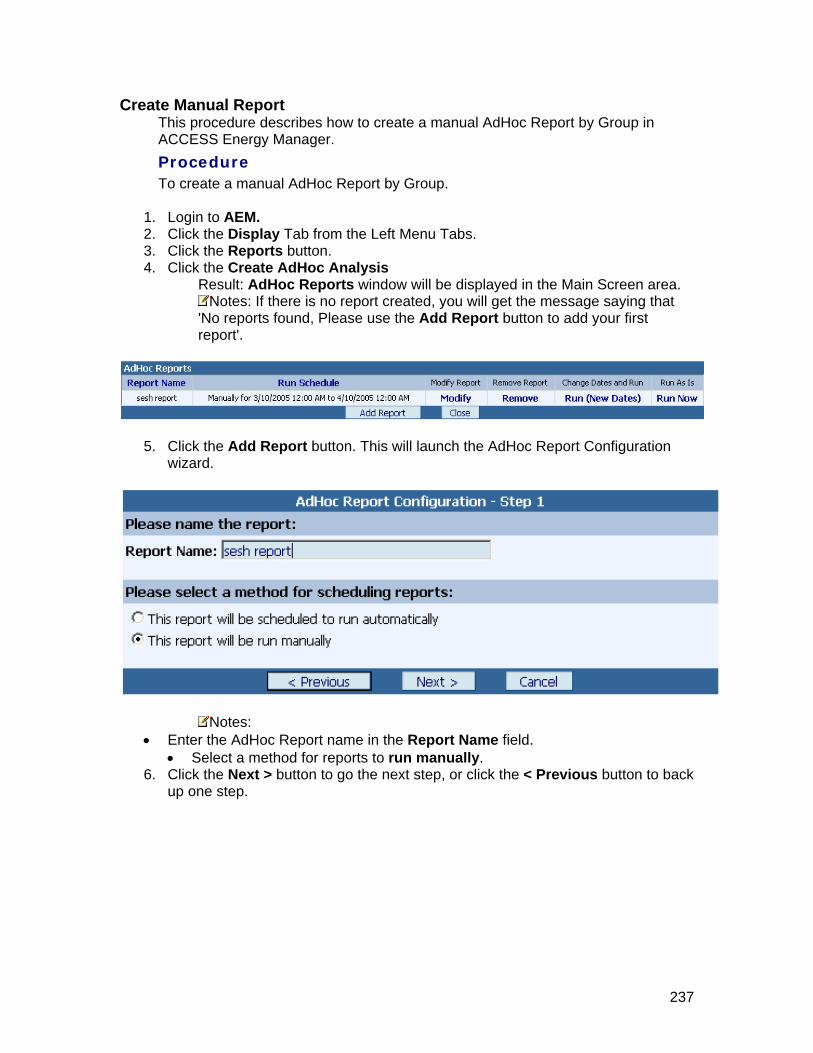
Create Manual Report is procedure describes how to create a manual AdHoc Report by Group in
A
T
om the Left Menu Tabs.
sis d in the Main Screen area.
ThCCESS Energy Manager.
Procedure
o create a manual AdHoc Report by Group.
ogin to AEM. 1. L2. Click the Display Tab fr
Click the Reports button. 3. 4. Click the Create AdHoc Analy
AdHoc Reports window will be displayeResult:Notes: If there is no report created, you will get the message saying that
'No reports found, Please use the Add Report button to add your first ort'. rep
Click the Add Report button. This will launch the AdHoc Report Configuration wizard.
5.
Notes: • Enter the AdHoc Report name in the Report Name field.
• Select a method for reports to run manually. 6. Click the Next > button to go the next step, or click the < Previous button to back
up one step.
237

7. Select a Start Date and Time for the AdHoc Report Cycle to start. Notes: If you want to use Calendar for your reference, You may click the
Show Calendar button. 8. Select a Stop Date and Time for the AdHoc Report Cycle to end.
Notes: If you want to reset the Start and Stop Time, you may click the Clear Times button. This will reset the times.
9. Click the Next > button to go the next step, or click the < Previous button to back up one step.
10. By using Add> or Add All >> or <Remove or <<Remove All buttons, select the registers of your choice across all devices in your system to be part of this report
11. Click the Save button to save the AdHoc Report, or click the < Previous button to back up one step.
12. Click the Save button. Result : AdHoc Report Configuration window is displayed with the message saying "Saving AdHoc Report Configuration...".
238

Then it goes to the AdHoc Reports window with the added report in the Main Screen area.
Notes: To run the AdHoc Report, click here
239

Create Scheduled Report This procedure describes how to create a scheduled AdHoc Report by Group in ACCESS Energy Manager. Procedure
To create a scheduled AdHoc Report by Group.
1. Login to AEM. 2. Click the Display Tab from the Left Menu Tabs. 3. Click the Reports button. 4. Click the Create AdHoc Analysis
Result: AdHoc Reports window will be displayed in the Main Screen area. Notes: If there is no report created, you will get the message saying that
'No reports found, Please use the Add Report button to add your first report'.
5. Click the Add Report button. This will launch the AdHoc Report Configuration wizard.
Notes: • Enter the AdHoc Report name in the Report Name field.
• Select a method for reports to run automatically. 6. Click the Next > button to go the next step, or click the < Previous button to back
up one step.
240

7. From the Start Time drop-down list, select a Start Time for the AdHoc Report Cycle to start.
8. From the Run Frequency drop-down list, select a Run Frequency for the AdHoc Report Cycle to run the report.
9. From the Select a report duration drop-down list, select report duration for the AdHoc Report data used in the report.
10. From the Optional E-mail notification drop-down list, select a contact person to notify through email after completing the scheduled report.
Notes: • Email notification is optional. • You have to check the checkbox to enable the Contact list.
11. Click the Next > button to go the next step, or click the < Previous button to back up one step.
12. By using Add> or Add All >> or <Remove or <<Remove All buttons, select the registers of your choice across all devices in your system to be part of this report
241

242
13. Click the Save button to save the AdHoc Report, or click the < Previous button to back up one step.
14. Click the Save button. Result : AdHoc Report Configuration window is displayed with the message saying "Saving AdHoc Report Configuration...".
Then it goes to the AdHoc Reports window with the added report in the Main Screen area.
Notes: To run the AdHoc Report, click here
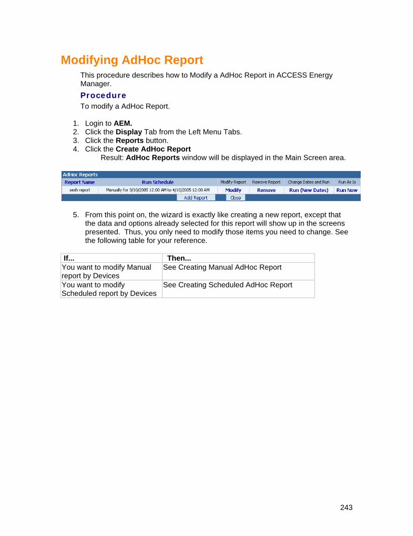
243
Modifying AdHoc Report This procedure describes how to Modify a AdHoc Report in ACCESS Energy Manager. Procedure
To modify a AdHoc Report.
1. Login to AEM. 2. Click the Display Tab from the Left Menu Tabs. 3. Click the Reports button. 4. Click the Create AdHoc Report
Result: AdHoc Reports window will be displayed in the Main Screen area.
5. From this point on, the wizard is exactly like creating a new report, except that the data and options already selected for this report will show up in the screens presented. Thus, you only need to modify those items you need to change. See the following table for your reference.
If... Then... You want to modify Manual report by Devices
See Creating Manual AdHoc Report
You want to modify Scheduled report by Devices
See Creating Scheduled AdHoc Report

244
Removing AdHoc Report This procedure describes how to Remove an existing AdHoc Report in ACCESS Energy Manager. Procedure
To Remove a AdHoc Report.
1. Login to AEM. 2. Click the Display Tab from the Left Menu Tabs. 3. Click the Reports button. 4. Click the Create AdHoc Report
Result: AdHoc Reports window will be displayed in the Main Screen area.
5. Click the Remove link to the respective AdHoc Report that you want to remove. Result: This will launch a message window saying that "Are you sure you want to remove this report?". If you click 'Yes', then it will remove permanently; if you click 'No', then it will cancel the remove operation.

245
Run AdHoc Report This procedure describes how to Run a AdHoc Report in ACCESS Energy Manager. Procedure
To Run a AdHoc Report.
1. Login to AEM. 2. Click the Display Tab from the Left Menu Tabs. 3. Click the Reports button. 4. Click the Create AdHoc Reports
Result: AdHoc Reports window will be displayed in the Main Screen area.
5. Click the Change Dates and Run or Run As Is link to the respective AdHoc Report that you want to run.
Result: Run report window is displayed. Notes: You can change the Date and Times had you select the first option,
before you click the Run Report. • Select a new Start Date and Time for the AdHoc Report Cycle to start.
If you want to use Calendar for your reference, you may click the Show Calendar button.
• Select a new Stop Date and Time for the AdHoc Report Cycle to end. If you want to reset the Start and Stop Time, you may click the Clear Times button. This will reset the times.
6. Click the Run Report button

246
Result: The AdHoc Report is now being processed.
• You may click Wait for results button to view a list of completed reports. • You may click Report Main Page button to configure or run another report. • You may click Close button to leave reports.
What to do next
View AdHoc Report

247
View Existing Reports
Viewing Billing Reports This procedure describes how to view a Billing Report in ACCESS Energy Manager. Procedure
To create a Billing Report.
1. Login to AEM. 2. Click the Display Tab from the Left Menu Tabs. 3. Click the Reports button. 4. Click the View Billing Report
Result: View Billing Reports window will be displayed in the Main Screen area.
5. Click the View link to the respective Billing Report that you want to see. This will show the Billing Report that was generated at the Run Date time. It does NOT run the report again -- it merely displays the results from a previous run. Here is the Billing report that was generated.

248
6. If you wish to remove a finished report from the view list, click the Remove link to the respective Billing Report that you want to delete
Result: This will launch a message window saying that "Are you sure, you want to remove this report from the View Billing Report?". If you click 'Yes', then it will remove from the View Billing Report, else if you click 'No', then it cancel the remove operation.

249
Viewing Load Analysis Report This procedure describes how to view a Load Analysis Report in ACCESS Energy Manager. Procedure
To create a Billing Report.
1. Login to AEM. 2. Click the Display Tab from the Left Menu Tabs. 3. Click the Reports button. 4. Click the View Load Analysis
Result: View Load Analysis Reports window will be displayed in the Main Screen area.
5. Click the View link to the respective Load Analysis Report that you want to see. This will show the Load Analysis Report that was generated at the Run Date time. It does NOT run the report again -- it merely displays the results from a previous run. Here is the Load Analysis Report that was generated.

250
6. If you wish to remove a finished report from the view list, click the Remove link to the respective Load Analysis Report that you want to delete.
Result: This will launch a message window saying that "Are you sure you want to remove this report from View Load Analysis Report?". If you click 'Yes', then it will remove from the View Load Analysis Report. If you click 'No', then it cancel the remove operation.

251
View AdHoc Report This procedure describes how to view a AdHoc Report in ACCESS Energy Manager. Procedure
To create a Billing Report.
1. Login to AEM. 2. Click the Display Tab from the Left Menu Tabs. 3. Click the Reports button. 4. Click the View AdHoc Reports
Result: View AdHoc Reports window will be displayed in the Main Screen area.
5. Click the View link to the respective AdHoc Report that you want to see. This will show the AdHoc Report that was generated at the Run Date time. It does NOT run the report again -- it merely displays the results from a previous run. Here is the AdHoc Report that was generated.

252
6. If you wish to remove a finished report from the view list, click the Remove link to the respective AdHoc Report that you want to delete.
Result: This will launch a message window saying that "Are you sure you want to remove this report from View AdHoc Report?". If you click 'Yes', then it will remove from the View AdHoc Report. If you click 'No', then it cancels the remove operation.

253
AEM Device Reference
ACCESS Devices
Converters
About Ethernet Converter
Description An Ethernet Converter is a communications device that transfers data between an Ethernet LAN and devices designed for serial communications only (RS-232/485). Application You typically use an Ethernet Converter to allow your AEM computer to communicate with meters, relays, and trip units over an Ethernet LAN. Features An Ethernet Converter offers these features:
• Easy integration of devices with an RS-232/485 interface to a TCP/IP Ethernet or Token Ring network
• External case or internal PC board versions available • Firmware programmable through the serial or network port

254
Contacting Siemens
Technical Support Contact Siemens Technical Support by Phone: (800) 427 2256 Fax : (800) 428 2480 Mail Siemens Energy & Automation, Inc. Power Distribution Solutions 3333 Old Milton Parkway Alpharetta, GA 30005 Email: [email protected] www : http://www.sea.siemens.com/access

255
Glossary AEM
ACCESS Energy Manager Data Logs
If you need a historical or trend log of device data during normal system operation. You can use the data to periodically generate graphs of power demand and power factor.
DNS Domain Name System
IIS Internet Information Services
Interval Offset To capture the first data sample at a time that is offset from the start Data Logs time by a specified amount
IP Address Internet Protocol Address
Log Interval To capture the data using a different sampling rate
MSMQ Microsoft® Message Queuing (MSMQ) technology enables applications running at different times to communicate across heterogeneous networks and systems that may be temporarily offline. Applications send messages to queues and read messages from queues. MSMQ provides guaranteed message delivery, efficient routing, security, and priority-based messaging. It can be used to implement solutions for both asynchronous and synchronous scenarios requiring high performance.
Polling Rate Polling rate is that how often the AEM browser client Polls the data from the AEM Server
RME Regional Marketing Engineers
THD Total Harmonic Distortion
TOU Time of Use

256
Index
A About AEM Alarms......................................................................................73 About AEM Interface ..................................................................................24 About AEM Toolbar.....................................................................................27 About Data logs .........................................................................................93 About Ethernet Converter.........................................................................253 About Realtime Trends .............................................................................103 Adding ......................................... 37, 45, 47, 49, 51, 65, 69, 70, 77, 85, 94, 104
Alarms ....................................................................................................85 Default Alarms ........................................................................................77 Device to a Group ....................................................................................70 MODBUS/COM .........................................................................................49 MODBUS/Ethernet...................................................................................51 New Connection ......................................................................................45 New Data logs .........................................................................................94 New Device .............................................................................................65 New Group ..............................................................................................69 New Projects ...........................................................................................37 Realtime Trends ....................................................................................104 SEABUS/COM ..........................................................................................45 SEABUS/Ethernet ....................................................................................47
AEM Connection Types ...............................................................................41 AEM Features .............................................................................................13
B Billing Report ...........................................................................................196
C Changing User Access ..............................................................................154 Clear Settings ..........................................................................................191 Configuration .............................................................................................36 Configuring ........................................................................................ 29, 187
Device Configuration .............................................................................187 Your Computer Display ............................................................................29 Your IIS ..................................................................................................33 Your Internet Explorer ............................................................................30
Contact Siemens ......................................................................................254 Contents & Organization ............................................................................16 Create Reports ..................................................................................197, 221
Manual Billing Report Report by Devices...............................................................................197 Report by Group .................................................................................202
Manual Load Analysis Report By Devices ..........................................................................................221 By Group ............................................................................................224
Scheduled Billing Report Report by Devices...............................................................................206

257
Report by Group .................................................................................211 Scheduled Load Analysis Report
By Devices ..........................................................................................227 By Group ............................................................................................230
D Deleting ...................................................................................................150
AEM Event Logs .....................................................................................150 Display.....................................................................................................161 Download Exported DataLogs...................................................................173
E Export Data logs ......................................................................................101
G Getting Started ..........................................................................................18
H How To... ...................................................................................................28
I Install IIS 5.0 ............................................................................................32 Install MSMQ..............................................................................................32 Introduction to AEM ...................................................................................13
L Launch Access Energy Manager..................................................................31 Load Analysis Report................................................................................220 Login AEM ..................................................................................................23 Logout AEM ................................................................................................23
M Modify.............................................................................67, 98, 155, 216, 233
Alarms ....................................................................................................88 Billing Report ........................................................................................216 Datalogs..................................................................................................98 Default Alarms ........................................................................................80 Devices ...................................................................................................67 Load Analysis Report .............................................................................233 MODBUS/COM .........................................................................................58 MODBUS/Ethernet...................................................................................59 Realtime Trends ....................................................................................108 SEAbus/COM ..................................................................................... 45, 55 SEABUS/Ethernet ....................................................................................56 Users Password.....................................................................................155
O Open Project ..............................................................................................38
R Removing....................................40, 62, 68, 72, 83, 91, 100, 110, 156, 217, 234

258
Alarms ....................................................................................................91 Billing Report ........................................................................................217 Connections ............................................................................................62 Data logs...............................................................................................100 Default Alarms ........................................................................................83 Devices ...................................................................................................68 Exported DataLogs ................................................................................174 Groups ....................................................................................................72 Load Analysis Report .............................................................................234 Projects...................................................................................................40 Realtime Trends ....................................................................................110 Users.....................................................................................................156
Renaming............................................................................................. 39, 71 Group ......................................................................................................71 Projects...................................................................................................39
Reset Factory Settings ...............................................................................84 Resetting Connections................................................................................63 Run Billing Report ....................................................................................218 Run Load Analysis Report.........................................................................235
S Setting Up Contacts..................................................................................157 Setting up Email Contact ............................................................................75 Setting Up Preferences.............................................................................159 Setup .........................................................................................................36
Setup Data logs .......................................................................................92 Setup Devices..........................................................................................64 Setup Projects.........................................................................................36
Software Installation .................................................................................21 Special Instructions ...................................................................................34 Status Bar ..................................................................................................24 System Requirements ................................................................................20
T Technical Support ....................................................................................254 Toolbar ................................................................................................ 24, 27
U Understanding AEM....................................................................................19 UnInstall AEM ............................................................................................35 User ID ....................................................................................................152 User Security Settings..............................................................................154
V Viewing 97, 107, 162, 163, 167, 169, 171, 172, 175, 178, 180, 181, 182, 183, 185,
192, 247, 249 Active Alarm List ...................................................................................171 Alarm List..............................................................................................169 Billing Reports.......................................................................................247 Connection List......................................................................................163 Data logs List ........................................................................................172 Datalogs..................................................................................................97
259
Default Alarm List .................................................................................167 Device List ............................................................................................166 EventLogs List .......................................................................................178 Groups ..................................................................................................181 Load Analysis Report .............................................................................249 Project List............................................................................................162 Realtime Data .......................................................................................183 Realtime Trending .................................................................................185 Realtime Trends ....................................................................................107 Realtime Trends List..............................................................................175 Scheduled Jobs List ...............................................................................180 Standard Diagram .................................................................................182 Summary Data ......................................................................................192
W Welcome ....................................................................................................13