Embed Size (px)
Citation preview
Access Network Dimensioning Rules Page 1 of 14
Network & TechnologyFundamental Planning
Access Network Dimensioning RulesLong run incremental costing model input
Telstra Corporation LimitedABN 33 - 051 775 556
Access Network Dimensioning Rules Page 2 of 14
TABLE OF CONTENTS1. PURPOSE.................................................................................................................3
2. SCOPE......................................................................................................................3
2.1. Area Categorisation ..........................................................................................3
3. NETWORK ARCHITECTURE...................................................................................4
3.1. General .............................................................................................................4
3.1.1. Transmission Limit Considerations.............................................................4
3.2. Distribution Network..........................................................................................6
3.2.1. Distribution Conduits ..................................................................................7
3.2.2. Distribution Pits ..........................................................................................8
3.2.3. Distribution Cables .....................................................................................8
3.2.4. Dimensioning of Distribution Cables.........................................................10
3.3. Feeder Network ..............................................................................................10
3.3.1. Placing and Sizing of Pillars .....................................................................10
3.3.2. Feeder Cables..........................................................................................10
3.3.3. Feeder Conduits.......................................................................................12
3.3.4. Feeder manholes and Pits........................................................................12
3.3.5. Placing and Sizing Fibre Multiplexers.......................................................14
Access Network Dimensioning Rules Page 3 of 14
1. PURPOSEThe purpose of this document is to provide a set of rules to enable the construction of a network costing model for Band 2 of the Telstra Australian customer access network.
These rules have been adopted because they represent efficient engineering best practices that a network provider would be expected to use in designing and deploying a copper wire customer access network in Band 2 today.
2. SCOPEFor the purposes of the model it is assumed that the following components of the existing network are to be retained:
• The Telephone Exchange location;
• Distribution Area boundaries;
• Pillar locations;
• Customer locations;
• Distribution and Main Cable routes are to be an optimized subset of the existing main cables and conduit routes from the exchange to the pillars using the existing right of ways, and the existing cables and conduit routes from the pillar to the customer premises using the existing right of ways.
The model will re dimension the following components of the network based on current best practice:
• The Feeder cables from the exchange to the pillar;
• The conduits to accommodate the feeder cables;
• The Distribution cables from the pillar to the customer premises;
• The conduits to accommodate the Distribution cables;
• The number and size of pits and manholes;
• Sizing of pillars;
• Optimise the jointing of cables; and
• Eliminate redundancies and inefficiencies in current cable routes
2.1. Area CategorisationAreas have been categorised as per the ULLS Bands.
Band 1 = CBD
Band 2 = Urban
Band 3 = Rural
Band 4 = Remote
This document contains the rules to be used for modelling Band 2.

Access Network Dimensioning Rules Page 4 of 14
3. NETWORK ARCHITECTURE
3.1. GeneralThe diagram below shows the different architectures currently existing in the copper network between the local telephone exchange and the customer.
The options shown in grey were used in the past to accommodate low occupancy and uncertain growth in the network. The additional point of flexibility provided by the cabinet allowed the feeder network to be run at a higher occupancy. These options are not used for new builds today, and are not to be used in the model.
• Not to be used in the model
o Cabinet fed pillar
o Direct Branch Cable fed customer
The options shown in blue are the current best practice for the pair copper network, and are to be used in the model.
• To be used in the model
o Direct Main Cable fed pillar
o Direct Main Cable fed customer
Exchange(Central Office)
Cabinet
(
(
(
(
Pillar
Pillar
Main Cable(Feeder Cable)
Branch Cable
Distribution Cable
Cabinet Fed Pillar
Direct Main Cable Fed
Direct Main Cable Fed Pillar
Direct Branch Cable Fed
Exchange(Central Office)
Cabinet
(
(
(
(
Pillar
Pillar
Main Cable(Feeder Cable)
Branch Cable
Distribution Cable
Cabinet Fed Pillar
Direct Main Cable Fed
Direct Main Cable Fed Pillar
Direct Branch Cable Fed
3.1.1. Transmission Limit ConsiderationsThe only cable gauges installed in the network today are listed below;
• The smallest gauge cable, 0.32mm, has inadequate transmission properties for normal urban use so is only used in areas where there is limited housing capacity and a short loop length requirement to the customer. In this model, 0.32mm cable would only be used in a CBD environment as sufficient duct space would be created in urban areas to install standard cable sizes.
Access Network Dimensioning Rules Page 5 of 14
• The 0.40mm gauge cable is the cable of choice in urban areas. In practice, it should be the heaviest cable gauge installed into the urban network today as network beyond the transmission limits of that cable should be on a fibre fed technology. For the purpose of this model, 0.64mm gauge cable may be used in urban areas to reach customers in DA’s which are currently fed by cable but are beyond 0.40mm transmission limits.
• The heavier gauge cables are most often used in Rural and Remote areas. Of these, 0.64mm is currently the most widely used and is often used beyond its stated transmission limit, with voice levels maintained by utilising loading coils and additional active gain devices. 0.90mm cable was used in the rural and remote environments in the past for customers having excessive distance from the communications building, in recent times 0.64mm cable with active gain devices has mostly replaced 0.90mm cable.
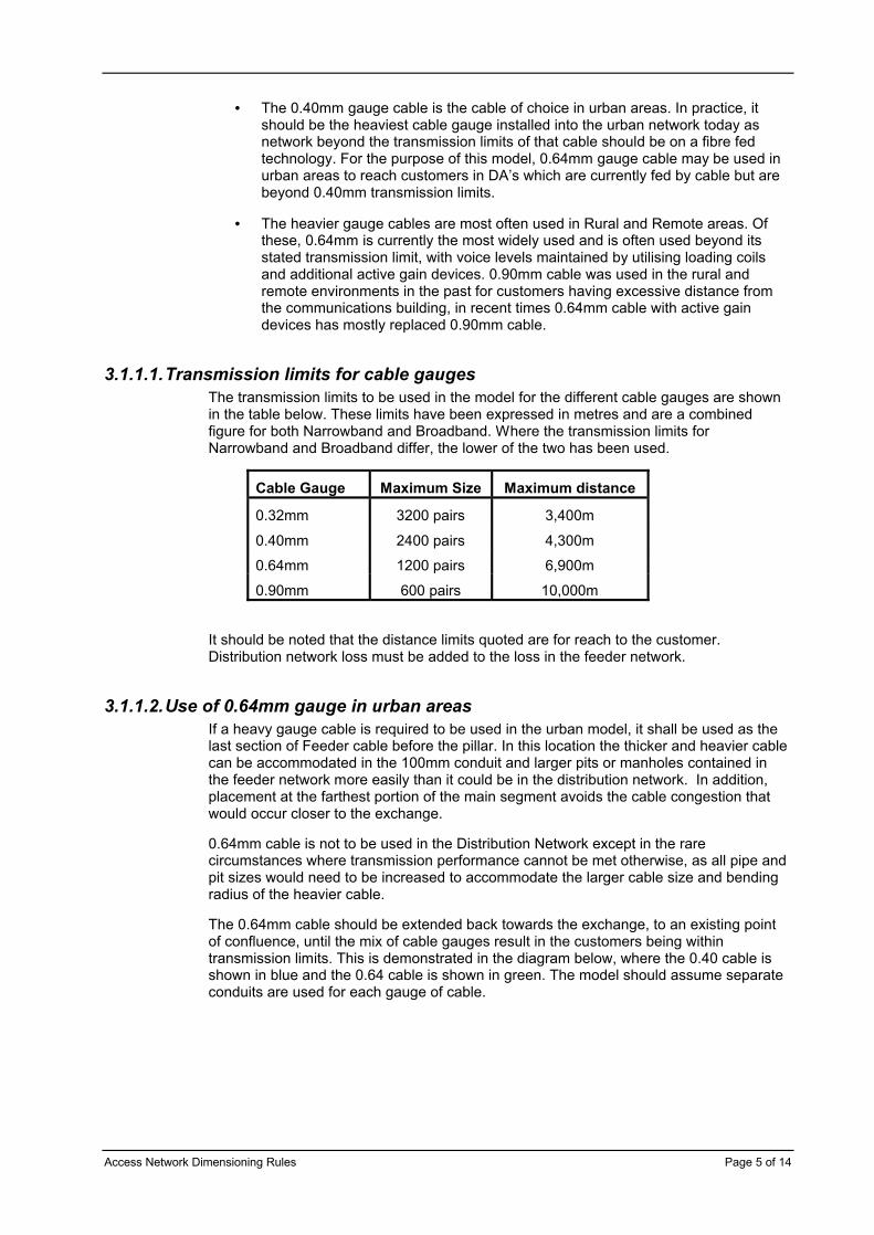
3.1.1.1.Transmission limits for cable gaugesThe transmission limits to be used in the model for the different cable gauges are shown in the table below. These limits have been expressed in metres and are a combined figure for both Narrowband and Broadband. Where the transmission limits for Narrowband and Broadband differ, the lower of the two has been used.
Cable Gauge Maximum Size Maximum distance
0.32mm 3200 pairs 3,400m
0.40mm 2400 pairs 4,300m
0.64mm 1200 pairs 6,900m
0.90mm 600 pairs 10,000m
It should be noted that the distance limits quoted are for reach to the customer. Distribution network loss must be added to the loss in the feeder network.
3.1.1.2.Use of 0.64mm gauge in urban areasIf a heavy gauge cable is required to be used in the urban model, it shall be used as the last section of Feeder cable before the pillar. In this location the thicker and heavier cable can be accommodated in the 100mm conduit and larger pits or manholes contained in the feeder network more easily than it could be in the distribution network. In addition, placement at the farthest portion of the main segment avoids the cable congestion that would occur closer to the exchange.
0.64mm cable is not to be used in the Distribution Network except in the rare circumstances where transmission performance cannot be met otherwise, as all pipe and pit sizes would need to be increased to accommodate the larger cable size and bending radius of the heavier cable.
The 0.64mm cable should be extended back towards the exchange, to an existing point of confluence, until the mix of cable gauges result in the customers being within transmission limits. This is demonstrated in the diagram below, where the 0.40 cable is shown in blue and the 0.64 cable is shown in green. The model should assume separate conduits are used for each gauge of cable.

Access Network Dimensioning Rules Page 6 of 14
200/0.64400/0.64
200/0.40400/0.40800/0.401200/0.40
200/0.64400/0.64
200/0.40400/0.40800/0.40 200/0.40400/0.40800/0.401200/0.40
Three factors need to be taken into account when determining the relative mix of the cable gauge. These are:
• The maximum distance from a pillar the farthest customer in the distribution network (Dd)
• The route length between the pillar and the exchange (Df)
• The points at which joints are located between the pillar and the exchange. Distances referred to are those distances between the pillar and the joint.
The distance from the exchange to the farthest customer in a DA, D=Dd+Df
If D<=4300m, 0.40 cable is to be used.
If D>4300m, a mix of 0.40 and 0.64 cable is to be used. 0.64 cable is only to be used in the feeder network.
The following formula should be used to determine the minimum length of 0.64 cable required to ensure all customers are within transmission limits:
61.1168.256.0
5.65.156.0
5.6)(5.164.0 −=
−=
−+= DDDD
D df
It should be noted that D0.64 should not exceed Df.
Once D0.64 is known, the closest joint in the feeder network from the pillar back to the exchange exceeding D0.64 should be used as the point at which 0.64 cable is no longer required.
For each cable gauge, demand should be aggregated separately on common routes.
3.2. Distribution NetworkThe model is to use a 100 pair non tapered cable architecture. This is the standard network architecture used by Telstra for deployment in new estates and is appropriate for a new start approach to modelling the network.
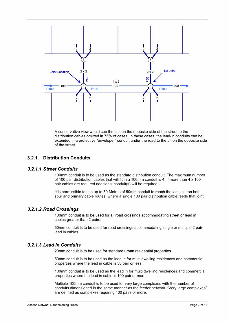
Reticulation along one side of the street with road crossings to provide the connection to allotments on the other side of the street is the preferred method of plant layout. Road crossings should generally feed two allotments each, and joints should feed 8 allotments as shown in the diagram below. The circles in the diagram represent P5 distribution pits.
Access Network Dimensioning Rules Page 7 of 14
2 2 2 2
2 22 2
100 1004 x 2
2 x 22 x 2
100
Joint Location No Joint
55
55P100 P100 P100
P50
P50
2 2 2 2
2 22 2
100 1004 x 2
2 x 22 x 2
100
Joint Location No Joint
5555
5555P100 P100 P100
P50
P50
A conservative view would see the pits on the opposite side of the street to the distribution cables omitted in 75% of cases. In these cases, the lead-in conduits can be extended in a protective “enveloper” conduit under the road to the pit on the opposite side of the street.
3.2.1. Distribution Conduits
3.2.1.1.Street Conduits100mm conduit is to be used as the standard distribution conduit. The maximum number of 100 pair distribution cables that will fit in a 100mm conduit is 4. If more than 4 x 100 pair cables are required additional conduit(s) will be required.
It is permissible to use up to 50 Metres of 50mm conduit to reach the last joint on both spur and primary cable routes, where a single 100 pair distribution cable feeds that joint.
3.2.1.2.Road Crossings100mm conduit is to be used for all road crossings accommodating street or lead in cables greater than 2 pairs.
50mm conduit is to be used for road crossings accommodating single or multiple 2 pair lead in cables.
3.2.1.3.Lead in Conduits20mm conduit is to be used for standard urban residential properties
50mm conduit is to be used as the lead in for multi dwelling residences and commercial properties where the lead in cable is 50 pair or less.
100mm conduit is to be used as the lead in for multi dwelling residences and commercial properties where the lead in cable is 100 pair or more.
Multiple 100mm conduit is to be used for very large complexes with the number of conduits dimensioned in the same manner as the feeder network. “Very large complexes” are defined as complexes requiring 400 pairs or more.
Access Network Dimensioning Rules Page 8 of 14
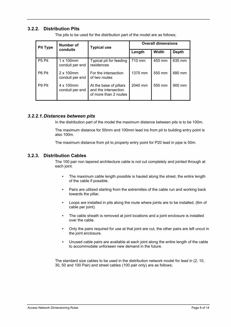
3.2.2. Distribution PitsThe pits to be used for the distribution part of the model are as follows;
Overall dimensionsPit Type Number of
conduits Typical useLength Width Depth
P5 Pit 1 x 100mm conduit per end
Typical pit for feeding residences
710 mm 455 mm 635 mm
P6 Pit 2 x 100mm conduit per end
For the intersection of two routes
1370 mm 550 mm 680 mm
P9 Pit 4 x 100mm conduit per end
At the base of pillarsand the intersection of more than 2 routes
2040 mm 550 mm 900 mm
3.2.2.1.Distances between pitsIn the distribution part of the model the maximum distance between pits is to be 100m.
The maximum distance for 50mm and 100mm lead ins from pit to building entry point is also 100m.
The maximum distance from pit to property entry point for P20 lead in pipe is 50m.
3.2.3. Distribution CablesThe 100 pair non tapered architecture cable is not cut completely and jointed through at each joint.
• The maximum cable length possible is hauled along the street, the entire length of the cable if possible.
• Pairs are utilized starting from the extremities of the cable run and working back towards the pillar.
• Loops are installed in pits along the route where joints are to be installed, (6m of cable per joint).
• The cable sheath is removed at joint locations and a joint enclosure is installed over the cable.
• Only the pairs required for use at that joint are cut, the other pairs are left uncut in the joint enclosure.
• Unused cable pairs are available at each joint along the entire length of the cable to accommodate unforseen new demand in the future.
The standard size cables to be used in the distribution network model for lead in (2, 10, 30, 50 and 100 Pair) and street cables (100 pair only) are as follows;

Access Network Dimensioning Rules Page 9 of 14
Approximate cable diameterPaircount
0.40 conductor
0.64 conductor
0.90 conductor
2 4.9 mm 7 mm 9.5 mm10 10 mm 14 mm 17 mm
30 13 mm 19 mm 26 mm
50 16 mm 24 mm 33 mm
100 19.1 mm 32 mm 45 mm
3.2.3.1.Street CablesOnly 100 pair cables will be used as street cables in the distribution network.
The distribution network will be dimensioned to allow one pair per service address and using a fill factor of 60%. This value represents a suitable compromise of the allowable fill factor from the standard network practice which allows a fill factor between 50% and 75%to be used depending on the particular network configuration encountered.
3.2.3.1.1 Maximum street cable distanceThe maximum cable haul length for distribution cable is 100m, because this cable is hauled by hand. A reasonable assumption is that 5 hauls of about 100m with 4 lay offs of cable means a maximum length of 100 pair distribution cable between joints will be 500m.
3.2.3.2.Lead in CablesLead in cables to be used in the model are, 2 pair for single residential and single line commercial properties, and 10, 30, 50 and 100 pair for multi dwelling residences and larger commercial properties.
3.2.3.2.1 Residential lead in cablesResidential lead in cables will be 2 pair.
The maximum length of 2 pair lead in cable along the street conduit is 100m.
The maximum number of 2 pair lead ins allowed from one joint is 15.
The maximum number of 2 pair lead ins to be accommodated in one street conduit is 6. If a particular layout requires more than six 2 pair lead in cables to be accommodated in a street conduit the joint must be moved to a better location, or an additional joint installed.
3.2.3.2.2 Multi Dwelling Residences and Commercial PropertiesFor Multi Dwelling Residences the model should replicate the existing lead in where possible, if this cable size is not known the lead in should allow for 1.25 pairs per residence and then be rounded up to the next lead in cable size. Pairs allocated in the street cabling should equal the number of pairs in the lead in cable.
Commercial properties should replicate the existing lead in. The cable should be rounded up to the next lead in cable size if the existing lead in is a non standard size or comprise more than one cable. Pairs allocated in the street cabling should equal the number of pairs in the lead in cable.
Access Network Dimensioning Rules Page 10 of 14
3.2.4. Dimensioning of Distribution CablesDistribution cables should be dimensioned based on one pair per residence passed by the cable starting at the extremities of the cable and working back towards the pillar. A fill factor of 60% should be applied to each cable.
Larger lead ins should be added to the pair count in the street cable based on the pair count of the lead in for both residential and commercial properties.
In the case of a 100 pair lead in, it should be extended directly back to the pillar.
3.3. Feeder NetworkThe model is to use a standard tapered cable layout. The number of cable sizes is limited to reduce the inventory costs of managing cable stocks and to facilitate the best possible purchase price from the cable manufacturer.
3.3.1. Placing and Sizing of PillarsPillars are the point of connection between the Feeder Network and the Distribution Network. They are constructed with a number of cable pairs from the Feeder Network terminating on the exchange side and a generally larger number of cable pairs terminating on the Distribution side of the pillar. Provision is made for a connection or jumper wire to connect pairs from the feeder network to pairs in the distribution network. This allows a point of flexibility between the two parts of the network and allows different provisioning schemes to be used in each.
Generally the distribution network is provided with more cable pairs than the feeder network to compensate for the uncertainty of where individual services are going to be required. The pillar allows a lesser number of cable pairs to be used in the feeder part of the network as each of the fewer feeder pairs terminated on the pillar is able to be cross connected to each of the greater number of pairs from the distribution network.
Different types of pillars with differing total pair capacities have been used in the network in the past, however current best practice is to use the 900 type and 1800 type pillars. These pillars have a total capacity of 900 and 1800 pairs respectively.
Best practice calls for a maximum number of pairs to be terminated in each type of pillar to allow for maintenance of faulty terminal units and to allow the extension of the 900 type to a maximum 1800 pair’s capacity if required.
These maximum capacities allow one vacant entry port for this purpose;
900 type max feeder = 300 pairs, max distribution = 500 pairs
1800 type max feeder = 600 pairs, max distribution = 1000 pairs.
Pillars should be placed around the corner from the main conduit route to enable easier access for vehicles and a safer working environment for staff. For the purpose of the model allow approximately 30 metres of 2 way conduit and one No. 9 pit per pillar.
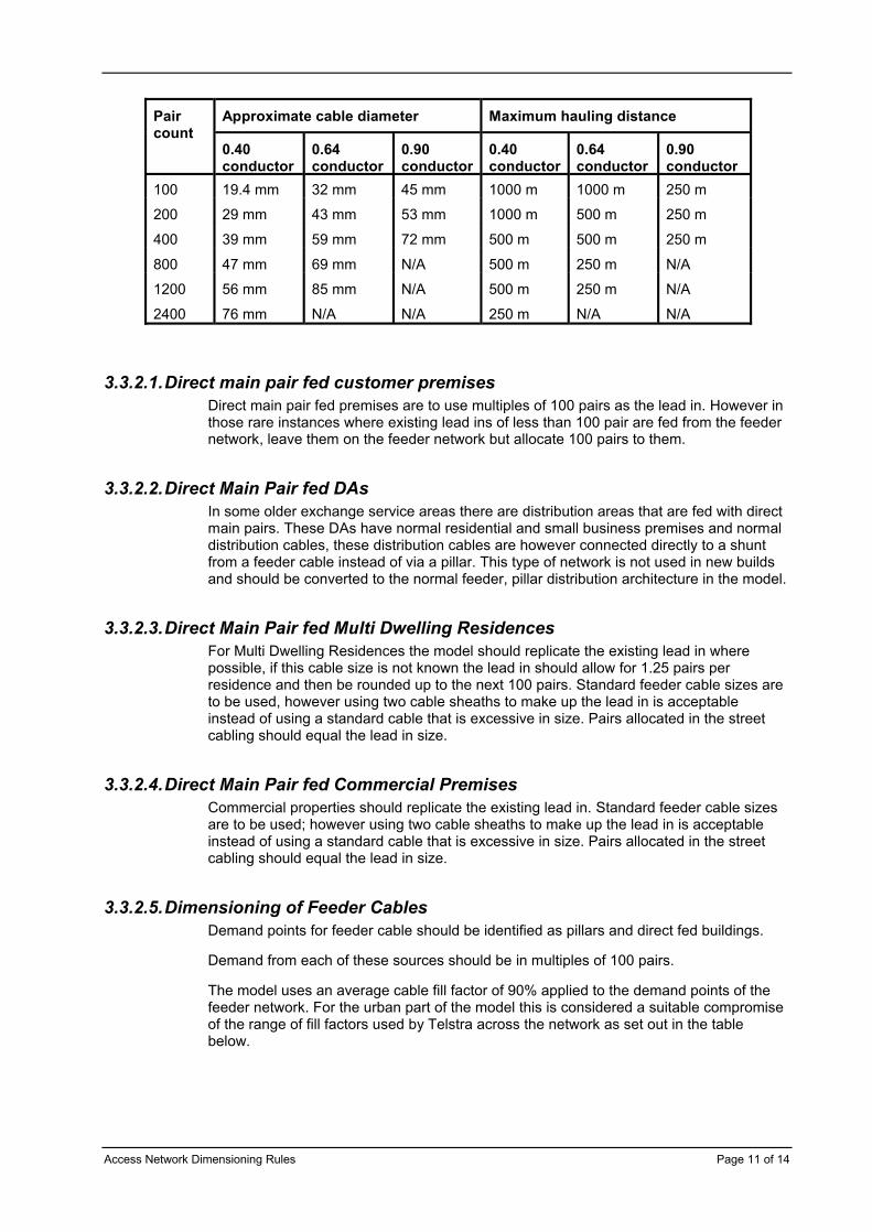
3.3.2. Feeder CablesThe standard size cables to be used in the feeder network model are as follows;
The approximate cable diameter and maximum hauling distance is shown for each cable size and conductor weight. Combinations marked as N/A are not available.
Access Network Dimensioning Rules Page 11 of 14
Approximate cable diameter Maximum hauling distancePaircount
0.40 conductor
0.64 conductor
0.90 conductor
0.40 conductor
0.64 conductor
0.90 conductor
100 19.4 mm 32 mm 45 mm 1000 m 1000 m 250 m
200 29 mm 43 mm 53 mm 1000 m 500 m 250 m
400 39 mm 59 mm 72 mm 500 m 500 m 250 m
800 47 mm 69 mm N/A 500 m 250 m N/A
1200 56 mm 85 mm N/A 500 m 250 m N/A
2400 76 mm N/A N/A 250 m N/A N/A
3.3.2.1.Direct main pair fed customer premisesDirect main pair fed premises are to use multiples of 100 pairs as the lead in. However in those rare instances where existing lead ins of less than 100 pair are fed from the feeder network, leave them on the feeder network but allocate 100 pairs to them.
3.3.2.2.Direct Main Pair fed DAsIn some older exchange service areas there are distribution areas that are fed with direct main pairs. These DAs have normal residential and small business premises and normal distribution cables, these distribution cables are however connected directly to a shunt from a feeder cable instead of via a pillar. This type of network is not used in new builds and should be converted to the normal feeder, pillar distribution architecture in the model.
3.3.2.3.Direct Main Pair fed Multi Dwelling ResidencesFor Multi Dwelling Residences the model should replicate the existing lead in where possible, if this cable size is not known the lead in should allow for 1.25 pairs per residence and then be rounded up to the next 100 pairs. Standard feeder cable sizes are to be used, however using two cable sheaths to make up the lead in is acceptable instead of using a standard cable that is excessive in size. Pairs allocated in the street cabling should equal the lead in size.
3.3.2.4.Direct Main Pair fed Commercial PremisesCommercial properties should replicate the existing lead in. Standard feeder cable sizes are to be used; however using two cable sheaths to make up the lead in is acceptable instead of using a standard cable that is excessive in size. Pairs allocated in the street cabling should equal the lead in size.
3.3.2.5.Dimensioning of Feeder CablesDemand points for feeder cable should be identified as pillars and direct fed buildings.
Demand from each of these sources should be in multiples of 100 pairs.
The model uses an average cable fill factor of 90% applied to the demand points of the feeder network. For the urban part of the model this is considered a suitable compromise of the range of fill factors used by Telstra across the network as set out in the table below.
Access Network Dimensioning Rules Page 12 of 14
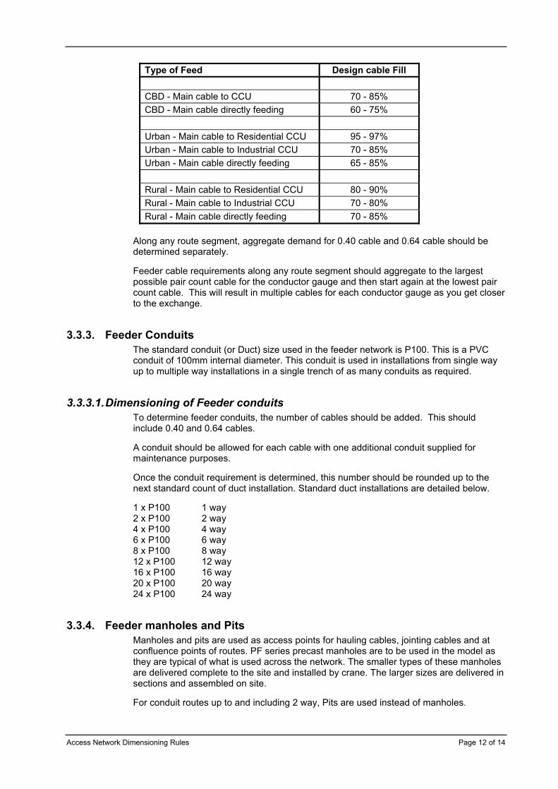
Type of Feed Design cable Fill
CBD - Main cable to CCU 70 - 85%CBD - Main cable directly feeding 60 - 75%
Urban - Main cable to Residential CCU 95 - 97%Urban - Main cable to Industrial CCU 70 - 85%Urban - Main cable directly feeding 65 - 85%
Rural - Main cable to Residential CCU 80 - 90%Rural - Main cable to Industrial CCU 70 - 80%Rural - Main cable directly feeding 70 - 85%
Along any route segment, aggregate demand for 0.40 cable and 0.64 cable should be determined separately.
Feeder cable requirements along any route segment should aggregate to the largest possible pair count cable for the conductor gauge and then start again at the lowest pair count cable. This will result in multiple cables for each conductor gauge as you get closer to the exchange.
3.3.3. Feeder ConduitsThe standard conduit (or Duct) size used in the feeder network is P100. This is a PVC conduit of 100mm internal diameter. This conduit is used in installations from single way up to multiple way installations in a single trench of as many conduits as required.
3.3.3.1.Dimensioning of Feeder conduitsTo determine feeder conduits, the number of cables should be added. This should include 0.40 and 0.64 cables.
A conduit should be allowed for each cable with one additional conduit supplied for maintenance purposes.
Once the conduit requirement is determined, this number should be rounded up to the next standard count of duct installation. Standard duct installations are detailed below.
1 x P100 1 way2 x P100 2 way4 x P100 4 way6 x P100 6 way8 x P100 8 way12 x P100 12 way16 x P100 16 way20 x P100 20 way24 x P100 24 way
3.3.4. Feeder manholes and PitsManholes and pits are used as access points for hauling cables, jointing cables and at confluence points of routes. PF series precast manholes are to be used in the model as they are typical of what is used across the network. The smaller types of these manholes are delivered complete to the site and installed by crane. The larger sizes are delivered in sections and assembled on site.
For conduit routes up to and including 2 way, Pits are used instead of manholes.
Access Network Dimensioning Rules Page 13 of 14
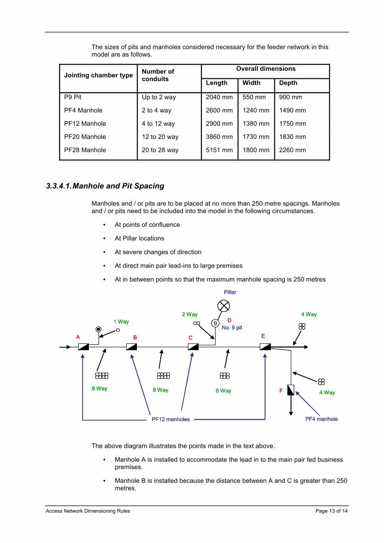
The sizes of pits and manholes considered necessary for the feeder network in this model are as follows.
Overall dimensionsJointing chamber type Number of
conduits Length Width Depth
P9 Pit Up to 2 way 2040 mm 550 mm 900 mm
PF4 Manhole 2 to 4 way 2600 mm 1240 mm 1490 mm
PF12 Manhole 4 to 12 way 2900 mm 1380 mm 1750 mm
PF20 Manhole 12 to 20 way 3860 mm 1730 mm 1830 mm
PF28 Manhole 20 to 28 way 5151 mm 1800 mm 2260 mm
3.3.4.1.Manhole and Pit Spacing
Manholes and / or pits are to be placed at no more than 250 metre spacings. Manholes and / or pits need to be included into the model in the following circumstances.
• At points of confluence
• At Pillar locations
• At severe changes of direction
• At direct main pair lead-ins to large premises
• At in between points so that the maximum manhole spacing is 250 metres
9
8 Way 8 Way 6 Way
4 Way
4 Way
2 Way1 Way
Pillar
PF4 manholePF12 manholes
No. 9 pit
F
E
D
CBA
99
8 Way 8 Way 6 Way
4 Way
4 Way
2 Way1 Way
Pillar
PF4 manholePF12 manholes
No. 9 pit
F
E
D
CBA
The above diagram illustrates the points made in the text above.
• Manhole A is installed to accommodate the lead in to the main pair fed business premises.
• Manhole B is installed because the distance between A and C is greater than 250 metres.
Access Network Dimensioning Rules Page 14 of 14
• Manhole C accommodates the pillar joints and conduits to the pillar around the corner from the main route.
• The No. 9 pit at D is to allow hauling of the cables from and to the pillar.
• Manhole E is to accommodate the confluence of two downstream conduit routes.
• Manhole F is to accommodate the change in direction of the conduit route heading south.
3.3.5. Placing and Sizing Fibre MultiplexersAs this model is to be used for the costing of existing ULL based services, all areas currently served by copper cable feeds are costed as such. For areas currently fed via Fibre Fed Multiplexers it is assumed that these multiplexers will be replaced by the current POTS only Multiplexer as used today the CMUX AU.
The CMUX AU Street Cabinet has two size options, fully equipped at 768 POTS services and half equipped at 384 POTS services.
The CMUX AU requires a CMUX NU Exchange Unit to parent the AU. The CMUX NU is installed at the local exchange and has the capability to parent up to 7 CMUX AU Street Cabinets.
The transport between the CMUX NU and CMUX AU is by optical fibre. The transmission system is single fibre working, however two fibres should be allowed per CMUX AU Street Cabinet installation.