Embed Size (px)
Citation preview
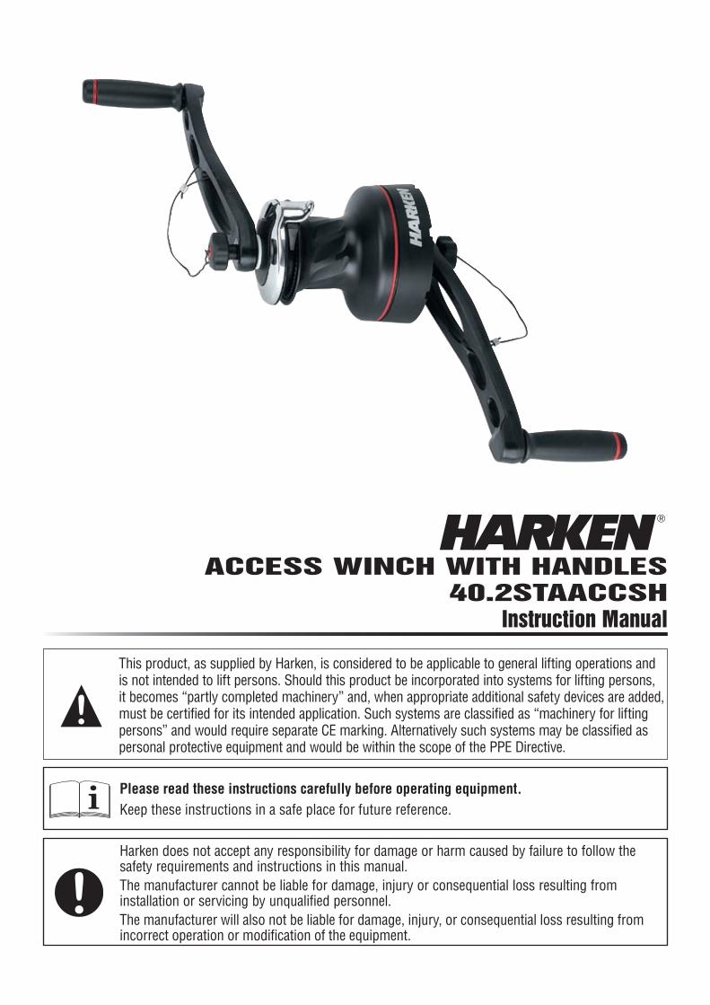
ACCESS WINCH WITH HANDLES 40.2STAACCSH
Instruction Manual
Harken does not accept any responsibility for damage or harm caused by failure to follow the safety requirements and instructions in this manual.The manufacturer cannot be liable for damage, injury or consequential loss resulting from installation or servicing by unqualified personnel.The manufacturer will also not be liable for damage, injury, or consequential loss resulting from incorrect operation or modification of the equipment.
Please read these instructions carefully before operating equipment.Keep these instructions in a safe place for future reference.i
This product, as supplied by Harken, is considered to be applicable to general lifting operations and is not intended to lift persons. Should this product be incorporated into systems for lifting persons, it becomes “partly completed machinery” and, when appropriate additional safety devices are added, must be certified for its intended application. Such systems are classified as “machinery for lifting persons” and would require separate CE marking. Alternatively such systems may be classified as personal protective equipment and would be within the scope of the PPE Directive.

2 Access Winch 05/17/10
Description
Part No.
ØHeight (H) Weight
Rope entry height (LE)
Rope Ø (Min - Max)
Fastener circle
Fasteners (SH or HH) Gear ratio Power ratioDrum (D) Base (B)
in mm in mm in mm lb kg in mm in mm in mm in mm 1 2 3 1 2 340.2STAACCS 31/8 80 63/16 157 67/8 175 8.4 3.8 31/4 82 5/16 - 1/2 8 - 12 47/8 123 5 x 1/4 5 x 6 2.13 6.28 — 13.50 39.90 —
A strong, lightweight manual rope-handling winch. Double handles provide maximum ergonomics, for high power and operation speed.
FEATurESMaximum Grip – The drum’s gripping surface is designed specifically to work with the drum diameter and material to maximize gripping power and reduce rope wear. Diagonal ribs stop the rope from rising (keeping rope wraps on part of drum where you have the best control), prevent overrides, and provide a smooth controlled release as rope exits the winch.
Spring-loaded, self-tailing jaws adjust under rope pressure to accept a variety of rope diameters. Teeth grip evenly with or without load.
Lightweight – Aluminium drums and high-strength composite self-tailing jaws and skirt save weight.
Powerful – Double-handle action allows optimum use of manpower to deliver power and speed.
Composite roller bearings reduce friction under load. Low friction and hardness properties make composites ideal for high-efficiency bearing systems.
Reliable & Easy to Maintain – Composite roller bearings and bushings don’t require lubrication and have excellent corrosion resistance. This “metal-replacement” material is completely nonreactive to saltwater and most chemicals, and has very good wear and abrasion resistance under maximum operating loads.
Load-carrying gears and pins are 17-4PH stainless steel for strength and durability.
Planetary gears are bronze to avoid stainless-on-stainless galling.
Snap-fit design keeps bearings captive in a high-strength Delrin cage when the drum is removed for maintenance.
Winches can be disassembled and serviced where mounted. The socket, washer, and screw-top snap-fit together to simplify maintenance and for quick and mistake-free assembly.
SELF-TAILING FOr EASY LINE CONTrOLLocking jaws hold loaded rope securely during operation and while suspended. The stripper arm is shaped to smoothly feed the rope in and out of the jaws so the operator can use both hands to turn the winch. The stripper arm adjusts to multiple positions after the winch is mounted so rope exit position can be optimized.
SPECIFICATIONSMaximum Working Load: Lifting Persons: 280 kg (test coefficient 10:1) See “LIMITATIONS” Page 3. Lifting Loads: 500 kg (test coefficient 5:1)Break Load: 2800 kg
Self-Tailing Stripper Arm
Hardkote, Teflon- Impregnated
Aluminum Drum and Castle
Bronze and Stainless Steel Gears
Composite Bearings
Self-Tailing Jaws
05/17/10 Access Winch 3
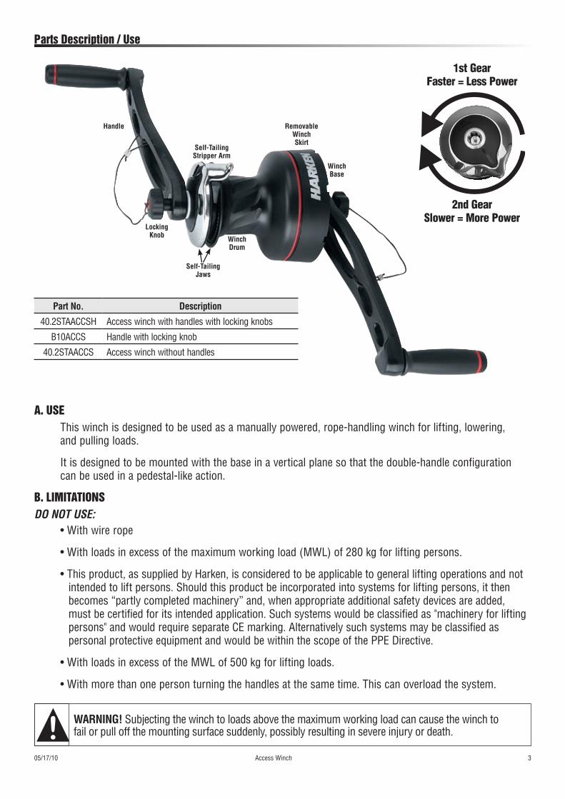
Parts Description / use
WARNING! Subjecting the winch to loads above the maximum working load can cause the winch to fail or pull off the mounting surface suddenly, possibly resulting in severe injury or death.
A. uSEThis winch is designed to be used as a manually powered, rope-handling winch for lifting, lowering, and pulling loads.
It is designed to be mounted with the base in a vertical plane so that the double-handle configuration can be used in a pedestal-like action.
B. LIMITATIONSDo not use:
• With wire rope
• With loads in excess of the maximum working load (MWL) of 280 kg for lifting persons.
• This product, as supplied by Harken, is considered to be applicable to general lifting operations and not intended to lift persons. Should this product be incorporated into systems for lifting persons, it then becomes “partly completed machinery” and, when appropriate additional safety devices are added, must be certified for its intended application. Such systems would be classified as "machinery for lifting persons" and would require separate CE marking. Alternatively such systems may be classified as personal protective equipment and would be within the scope of the PPE Directive.
• With loads in excess of the MWL of 500 kg for lifting loads.
• With more than one person turning the handles at the same time. This can overload the system.
Self-Tailing Stripper Arm
Handle
Locking Knob Winch
Drum
Self-Tailing Jaws
Removable Winch Skirt
Winch Base
Part No. Description
40.2STAACCSH Access winch with handles with locking knobs
B10ACCS Handle with locking knob
40.2STAACCS Access winch without handles
1st Gear Faster = Less Power
2nd Gear Slower = More Power
Installation
4 Access Winch 05/04/10
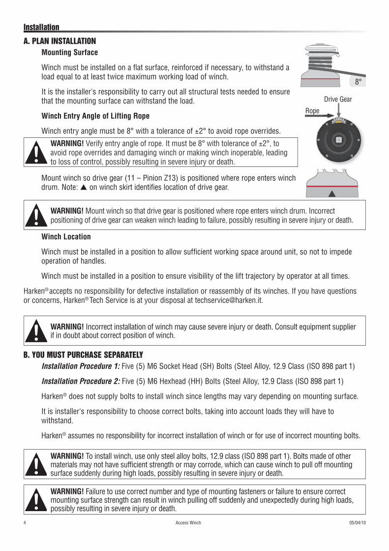
A. PLAN INSTALLATIONMounting Surface
Winch must be installed on a flat surface, reinforced if necessary, to withstand a load equal to at least twice maximum working load of winch.
It is the installer's responsibility to carry out all structural tests needed to ensure that the mounting surface can withstand the load.
Winch Entry Angle of Lifting Rope
Winch entry angle must be 8° with a tolerance of ±2° to avoid rope overrides.
B. YOu MuST PurCHASE SEPArATELYInstallation Procedure 1: Five (5) M6 Socket Head (SH) Bolts (Steel Alloy, 12.9 Class (ISO 898 part 1)
Installation Procedure 2: Five (5) M6 Hexhead (HH) Bolts (Steel Alloy, 12.9 Class (ISO 898 part 1)
Harken® does not supply bolts to install winch since lengths may vary depending on mounting surface.
It is installer's responsibility to choose correct bolts, taking into account loads they will have to withstand.
Harken® assumes no responsibility for incorrect installation of winch or for use of incorrect mounting bolts.
WARNING! To install winch, use only steel alloy bolts, 12.9 class (ISO 898 part 1). Bolts made of othermaterials may not have sufficient strength or may corrode, which can cause winch to pull off mounting surface suddenly during high loads, possibly resulting in severe injury or death.
WARNING! Incorrect installation of winch may cause severe injury or death. Consult equipment supplier if in doubt about correct position of winch.
WARNING! Failure to use correct number and type of mounting fasteners or failure to ensure correct mounting surface strength can result in winch pulling off suddenly and unexpectedly during high loads, possibly resulting in severe injury or death.
Mount winch so drive gear (11 – Pinion Z13) is positioned where rope enters winch drum. Note: s on winch skirt identifies location of drive gear.
WARNING! Verify entry angle of rope. It must be 8° with tolerance of ±2°, to avoid rope overrides and damaging winch or making winch inoperable, leading to loss of control, possibly resulting in severe injury or death.
Winch Location
Winch must be installed in a position to allow sufficient working space around unit, so not to impede operation of handles.
Winch must be installed in a position to ensure visibility of the lift trajectory by operator at all times.
Harken® accepts no responsibility for defective installation or reassembly of its winches. If you have questions
or concerns, Harken® Tech Service is at your disposal at [email protected].
WARNING! Mount winch so that drive gear is positioned where rope enters winch drum. Incorrect positioning of drive gear can weaken winch leading to failure, possibly resulting in severe injury or death.
Drive Gear
Rope
8°

Installation
05/04/10 Access Winch 5
4. Slide off hub (31) and cover (26).3. Slide off central shaft (28).
2. Slide off bushing (30).1. Remove ring (29).
C. PrOCEDurE 1
6. Remove self-tailing arm (26) by rotating and lifting it.
5. Loosen the three screws (25) (4Nm/35 in-lb)
To install winch you must remove drum. Use five (5) M6 Socket Head (SH) bolts into tapped mounting plate. You may also use washers and nuts (Steel Alloy, 12.9 Class (ISO 898 part 1).
Tools You Will Need
One medium flat-blade screwdriver
Protective gloves
Torque to apply when assembling
Use either Procedure 1 or 2 to install winch. Use Procedure 1 to thread mounting screws into threaded holes in mounting plate. You can also use washers and nuts. Procedure 2 takes less time but can only be used if you can tighten nuts from behind mounting plate.

6 Access Winch 05/04/10
Installation
7. Lift off drum (20). Install socket head bolts in winch.
PrOCEDurE 1 (CONTINuED)
2. Take off skirt (2).1. Carefully pry off skirt (2) using screwdriver placed as shown.
PrOCEDurE 2
Torque to apply when assembling
To install winch you must remove skirt as directed below. Use five (5) M6 Hexhead (HH) bolts, washers and nuts (Steel Alloy, 12.9 Class (ISO 898 part 1).
Tools You Will Need
One medium flat-blade screwdriver
Protective gloves
4. Correctly positioned bolts.3. Position 5 hexagonal headed (HH) bolts in holes.

Installation
05/04/10 Access Winch 7
6. Press down skirt to position correctly.5. Reposition skirt No. 2 in housing.
PrOCEDurE 2 (CONTINuED)
Note: Make sure skirt is correctly clipped on to base of winch.
FINAL INSTALLATION
1. Carry out Procedure 1 or Procedure 2, then install winch on a flat surface in selected position.2. Position base of winch in selected area and mark holes or use drilling template.Drilling template is available on Harken® website, www.harken.com. Download, print and compare template to winch to verify that size of template and hole position/sizes are correct. See reduced-size template on Page 8.
CAUTION! When downloading winch template make sure you have correct size paper and that printer will output at 100%. Before drilling holes verify that template is correct in every detail. Harken cannot be responsible for incorrectly drilled holes because of a faulty template.
3. Remove winch and drill five (5) 6.2 mm diameter clearance holes. If drilling and tapping consult industry standards for drill/tap size. Important: Do not countersink bolts.4. Bolt base of winch to support plate. Use bolts that are the correct length for thickness and type of support plate. Consult equipment supplier if in doubt. Procedure 1: Use five (5) M6 Socket Head (SH) bolts, washers, and nuts. If using threaded holes in mounting plate consult industry standards for minimum thread engagement for drilling and tapping. See Page 5. Procedure 2: Use five (5) M6 Hexhead (HH) bolts, washers, and nuts. See Page 6.5. To obtain correct Maximum Working Load (MWL) all five bolts, nuts, and washers must be securely tightened and there must be at least 21/2 threads showing below all five nuts.
WARNING! Failure to use correct number and length of mounting fasteners and/or failure to tighten them correctly so that at least 21/2 threads show below all nuts can result in winch pulling off suddenly and unexpectedly during high loads which may cause load to drop, possibly resulting in severe injury or death.

Installation
8 Access Winch 05/04/10
1. Reassemble winch following either Procedure 1 or 2 in reverse order and apply products indicated in Maintenance section.2. Position self-tailing arm so rope leaving winch leads to correct position—usually 4 or 5 o’clock.
rEASSEMBLE WINCH
POSITION HANDLES
3. Position handles at 180° to one another as shown in photo.
2. Thread locking knob on central shaft to secure handle and tighten.
1. Insert handle socket on central shaft.
FINAL INSTALLATION (CONTINuED)
Reduced-size drilling template. See Page 7 for important information about template.
Radial Winch 40
All dimensions in millimeters. Dimensions to be followed as indicated and not to be scaled.
Drive Gear (11 – Pinion Z13)

Operation
05/04/10 Access Winch 9
DANGER! Winch must not be used to lift people unless combined with suitable additional safety devices.
Wear gloves to protect against rope abrasion or chafe when rotating handles.
PErSONAL PrOTECTIVE EQuIPMENT
IMPORTANT! Keep fingers, loose clothing, hair, etc. away from winch. Area around winch handles should be kept clear of people and objects at all times. Be sure to keep loose rope near winch to prevent tripping.A. Start at base and wind rope onto drum in a clockwise direction. Use at least four (4) complete turns, but no more than six (6), depending on rope diameter. Excess turns may cause rope to override (overlap) or may cause excessive friction.
WARNING! Always put a minimum of four (4) turns on winch drum. Fewer turns can severely decrease holding power which may result in rope slippage or failure to hold load. Rope slippage or failure to hold load may cause lifted load to fall, possibly resulting in severe injury or death.
WARNING! Never allow rope to (override) overlap on winch drum. This can cause rope to jam and can prevent load from being lifted/lowered. Tension on rope to load must be relieved to clear override (overlap). This procedure carries a risk of serious injury or death if load drops or becomes uncontrollable.
LIFTING LOAD
Rope Ø Min. Rope Turns Max. Rope Turns8 mm 4 610 mm 4 512 mm 4 4
B. Ensure that the rope does not override (overlap) on winch.
C. Pull rope through to take up any slack, then load into spring-loaded, self-tailing jaws by winding rope clock wise and pulling tight to engage. Self-tailing jaws act as locking mechanism so operator does not have to pull rope in or let it out while rotating handles.
WARNING! Rope must be securely pulled into self-tailing jaws. Do not rely solely on rope turns to hold load. Stripper arm must be positioned correctly so line is not forced out of self-tailing jaws while rotat-ing handles. Check that rope remains secured in self-tailing jaws while cranking. Failure to securely pull rope into self-tailing jaws may cause rope slippage which can cause lifted load to fall, possibly resulting in severe injury or death.
INCORRECTCORRECT
Self-Tailing Jaws

Operation
10 Access Winch 05/17/10
LOWErING LOAD
WARNING! Use caution when lowering load using winch. Carefully hold rope when it is out of self-tailing jaws. Rope tail must not be released. Releasing rope tail will result in rope slippage. When lowering is completed, place line securely in self-tailing jaws. Rope turns alone may hold for a short time but will slip. Failure to hold load will cause it to fall, possibly resulting in severe injury or death.
We recommend using a safety device in the final operating system, such as a grab-rope mechanism (e.g. Prussic knot, rope-grab clutch). Engage grab rope mechanism or clamp rope turns on drum with your hand. Carefully unwind rope from self-tailing jaws only, while maintaining even tension on rope. Operator must hold rope, maintaining tension at all times unless it is securely fastened in self-tailing jaws.
WARNING! Do not take rope turns off winch drum until rope is completely unloaded. Taking turns off winch drum will result in rapid rope slippage and failure to hold load. Failure to hold load will cause it to fall, possibly resulting in severe injury or death.
D. Begin turning handles counterclockwise. Gears engage automatically depending on direction handles are rotated. 1st gear: rotate handles counterclockwise. 2nd gear: rotate handles clockwise.E. When handles become difficult to rotate in 1st gear, reverse direction to access 2nd. A higher power ratio makes a heavier load easier to lift with the same effort.
INCORRECTCORRECT
1st Gear Faster = Less Power
2nd Gear Slower = More Power
WARNING! Use caution when lowering load using winch. Carefully hold rope when it is out of self-tailing jaws. Rope tail must not be released. Releasing rope tail will result in rope slippage. When lowering is completed, place line securely in self-tailing jaws. Rope turns alone may hold for a short time but will slip. Failure to hold load will cause it to fall, possibly resulting in severe injury or death.
WARNING! Do not operate with more than one person turning the handles at the same time. This can overload the system, causing the winch or components to fail causing a fall resulting in severe injury or death.

Inspection
05/04/10 Access Winch 11
INSPECT BEFORE EACH USE
A formal inspection of the winch and its connection to the structure must be performed at least annually by a knowledgeable person other than the user. The inspection should be recorded in an inspection and maintenance log.BEFORE EACH USEInspect winch and self-tailing jaws for degradation, cracks, or wear that may affect locking strength and operation. Check lifting rope to make sure that it is free from wear. If in doubt, replace with a suitably strong rope.
HEAVY USE/HARSH ENVIRONMENTIn addition to inspection before each use, a detailed monthly inspection of the unit is recommended. If unit is under heavy use and/or in a harsh environment inspect and lubricate frequently.
6) Maintenance
WASHWash winch frequently with fresh water.
Do not allow cleaning products or other caustic solutions to come into contact with winch, especially anodized, chrome-plated, or plastic parts. Do not use solvents, polishes, or abrasive pastes on logos or winch stickers.
MAINTENANCE SCHEDULEWinch must be completely overhauled, cleaned, and lubricated at least every 12 months. Harsh environment and/or heavy use may require more frequent maintenance.
After inspection, replace worn or damaged components with genuine Harken parts. Do not replace or modify winch with a part that was not designed for it.
CAUTION! Periodic maintenance must be carried out regularly. Lack of adequate maintenance shortens the life of the winch, can cause serious injury and also invalidate the winch warranty. Installation and mainte-nance of winches must be carried out exclusively by trained personnel.
Carry out Procedure 1 as shown in Installation through step 5 and then do following:
Torque to apply when assembling
2. Remove stripper arm support (19).1. Completely unscrew three screws (25).
DISASSEMBLYTools You Will Need
Medium flat-blade screwdriver
Small flat-blade screwdriver
#5 Allen wrench
Protective gloves

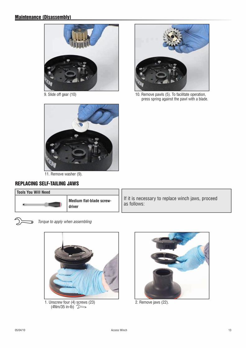
Maintenance (Disassembly)
12 Access Winch 05/04/10
6. Remove gear (7) and remove pawls (5). To facilitate operation, press spring against pawl with a blade.
5. Remove washer (12).
3. Unscrew six (6) socket head cap screws (15) (8Nm/71 in-lb)
8. Slide off gear (27).7. Slide off gear (3).
4. Remove Assy Housing
05/04/10 Access Winch 13
Maintenance (Disassembly)
11. Remove washer (9).
10. Remove pawls (5). To facilitate operation, press spring against the pawl with a blade.
9. Slide off gear (10)
2. Remove jaws (22).1. Unscrew four (4) screws (23) (4Nm/35 in-lb)
If it is necessary to replace winch jaws, proceed as follows:
Torque to apply when assembling
Tools You Will Need
Medium flat-blade screw-driver
rEPLACING SELF-TAILING JAWS

Maintenance
14 Access Winch 05/04/10
CLEAN1. Use degreaser to soak metal components. Rinse plastic parts in fresh water.2. Dry parts with rags that do not leave residue.3. Inspect gears, bearings, pins, and pawls for any signs of wear or corrosion.
4. Carefully check teeth of gears and ring gears to make sure there are no traces of wear.
5. Check roller bearings to ensure there are no breaks in bearing cages.
6. Replace worn or damaged components. See Page 14 and Parts on Pages 16 - 17.
LUBRICATE1. Carry out maintenance on components using products listed and shown below on exploded view.
2. Use brush to lightly lubricate all gears, gear pins, teeth, and all moving parts with Harken Grease.
3. Lightly lubricate pawls and springs with Harken Pawl Oil. Do not use grease on pawls!
G
G2G
G L
L
L
G
G
G
O
Location Harken Part No. ProductG BK4513 Harken® GreaseL — Loctite® 243™O BK4521 Harken® Pawl Oil
2 Apply Harken grease on drum gear
Tools You Will Need
Brush
BK4513
BK4521

05/04/10 Access Winch 15
Maintenance
Assemble winch in reverse order of sequence in the Disassembly section.
To tighten bolts, use torque indicated in disassembly procedure.
If jaws have been disassembled, insert peeler between two jaws, taking care that letters "TOP" on peeler are facing upwards.
When positioning stripper arm, align peeler with it.
ASSEMBLE PAWLSCorrectly position spring in housing as shown at left. Hold spring closed and slide pawl into housing. Once in position, check that pawls can be easily opened and closed with a finger.
If you have questions concerning the assembly procedure contact Harken® Tech Service: [email protected].
OIL
8) Handling
Protect against extreme temperatures: -10° C to +40° C
Extreme heat may distort composite parts.
Extreme cold can cause the material to become brittle and cause the lubrication to congeal.
9) Storage
Store in clean/dry place
Avoid impact damage which could damage jaws and skirt; ensure good packaging when shipping.
SPArE PArTSSpare parts can be ordered from Harken® as described in the Harken® Worldwide Limited Warranty using the part number in the Parts List and the serial number of the winch, which is printed on a plate on the drum support and also on the skirt.
W XXXXX XXXXXXXXX
7) Assembly
Last two numbers of the year of production, i.e. 10 for 2010.

Declaration of Conformity
15 Access Winch 05/04/10
12) Explanation of Label
Manufacturer — Harken Italy S. p. A. Via Marco Biagi, 14, 22070 Limido Comasco (CO) Italy
Telephone: 031.3520031 Web: www.harken.it, Email: [email protected]
EC Declaration of ConformityHarken Italy S.p.A. declares that the product described hereafter:
Access Winch – 40.2STAACCSHcomplies with the essential requirements of the Machinery Directive 2006/42/EC and
carries the appropriate CE marking.Compliance has been demonstrated with reference to the harmonized standard;
BS EN 13157:2004 Cranes — Safety - Hand powered lifting equipmentA technical file is retained for this equipment by the authorized manufacturer.
1. Manufacturer’s name2. Product name and code3. Manufacturer's address4. Pictogram instruction to read the manual5. CE marked and tested to EN13157.2004 standard6. Safety instruction to put a minimum of 4 rope wraps clockwise around drum; minimum rope diameter is 8 mm, maximum rope diameter is 12 mm7. Serial number in format: last two numbers of the year of production (i.e. 10 = year 2010)8. Warning! Maximum lifting load (maximum load for lifting persons)
ACCESS WINCH 40.2STAACCSHwww.harken.com
(+39) 031-3523511
Minumum 4 turns clockwise, rope Ø 8 - 12 mm
Break Load 2800 kg
Max Working Load Lifting Loads= 500kg (coefficient 5:1) Lifting persons= 280kg (coefficient 10:1)
Italy SpA
W XXXXX XXXXXXXXX
Serial No.EN13157.2004i
1 2
3 4 5
6 78
W XXXXX XXXXXXXXX
Done at:
_______________________________________________
On:
________________________
Signature
_______________________________________________
Andrea Merello Harken Italy S. p. A. Via Marco Biagi 220 Limido Comasco (CO) Italy
Harken Italy S.p.A. 28th April 2010

05/04/10 Access Winch 17
Parts
2
1
27
13
9
10
5
6
11
8
3
4
6
5
7
12
18
15
14
16
17
21
20
22
23
19
24
25
26
31
30
29
28
18 Access Winch 05/04/10
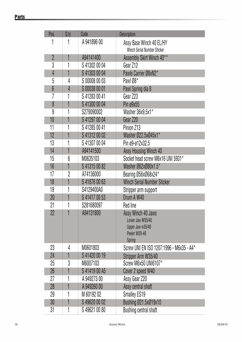
Parts
1 1 A 941896 00 Assy Base Winch 40 EL/HYWinch Serial Number Sticker
2 1 A94141400 Assembly Skirt Winch 40**3 1 S 41302 00 04 Gear Z124 1 S 41303 00 04 Pawls Carrier Ø8xN2*5 4 S 00008 00 03 Pawl Ø8*6 4 S 00038 00 01 Pawl Spring dia 87 1 S 41283 00 41 Gear Z238 1 S 41300 00 04 Pin ø9x559 1 S279090002 Washer 36x9,5x1*
10 1 S 41297 00 04 Gear Z2011 1 S 41285 00 41 Pinion Z1312 1 S 41312 00 02 Washer Ø22.5xØ45x1*13 1 S 41307 00 04 Pin ø9-ø12x32.514 1 A94141500 Assy Housing Winch 4015 6 M0635103 Socket head screw M6x16 UNI 5931*16 1 S 41315 00 82 Washer Ø62xØ80x1.5*17 2 A74136000 Bearing Ø56xØ68x24*18 1 S 41876 00 63 Winch Serial Number Sticker19 1 S4129400A0 Stripper arm support20 1 S 41417 00 53 Drum A W4021 1 S281680097 Red line22 1 A94131800 Assy Winch 40 Jaws
Lower Jaw W35/40Upper Jaw w35/40Peeler W20-40Spring
23 4 M0601803 Screw UNI EN ISO 1207:1996 - M6x35 - A4*24 1 S 41420 00 19 Stripper Arm W35/4025 3 M6007103 Screw M6x50 UNI6107*26 1 S 41419 00 A5 Cover 2 speed W4027 1 A 949273 00 Assy Gear Z2028 1 A 949260 00 Assy central shaft29 1 M 60192 02 Smalley ES1930 1 S 49620 00 02 Bushing Ø21.5xØ19x1031 1 S 49621 00 80 Bushing central shaft
Pos. Q.ty Code Description
05/04/10 Access Winch 19
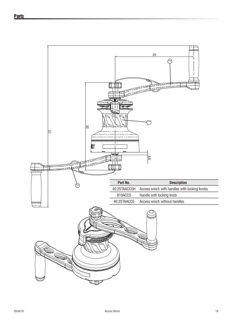
Parts
254
8,20
521
282
2
1
2 Part No. Description
40.2STAACCSH Access winch with handles with locking knobs
B10ACCS Handle with locking knob
40.2STAACCS Access winch without handles

ManufacturerHarken Italy SpA.
Via Marco Biagi 14, 22070 Limido Comasco (CO), Italy Tel 031.3523511; Fax 031.3520031
Web: www.harken.it Email: [email protected]
eu RepresentativeHarken UK Ltd
Bearing House, Ampress Lane Lymington, Hampshire S041 8LW, England
Telephone: (44) 01590-689122 • Fax: (44) 01590-610274 Web: www.harken.co.uk
Email: [email protected]
Worldwide Limited WarrantyRefer to the Harken Worldwide Limited Warranty on the website at http://www.harkenindustrial.com/warranty.php
05-17-10