Embed Size (px)
Citation preview

ACCESSORIES FOR LPOF, HPPT AND XLPE HIGH VOLTAGE CABLE SYSTEMS
PRODUCT CATALOGUE

hvGrid-tech designs and manufactures high voltage cable accessories for all types of cable systems, ranging from 69 kV to 350 kV, including:
• Low Pressure Oil Filled / Self Contained Fluid Filled (LPOF/SCFF)• High Pressure Pipe Type / High Pressure Fluid Filled (HPPT/HPFF)• Cross Linked Polyethylene (XLPE)
Our line of products include:
• Terminations – Outdoor, GIS, Oil immersed• Joints and Splice Kits• Pre-pressurized Oil Reservoirs • Grounding / Sheath Bonding Link Boxes • Cable Clamps – Standard and Custom Applications• Cable Support Systems – Standard and Custom Applications• Oil Line Insulators
hvGrid-tech owns proprietary accessory designs from the different lines of products that have been developed over time by Canada Wire & Cable, Alcatel Canada Wire and EHV Power. We can also custom design and manufacture accessories and components for virtually any underground high voltage cable system.

hvGrid’s terminations are based upon a proven design with over 50 years of service around the world in operating voltages from 69 kV up to 345 kV. They are designed for paper insulated single conductors, up to 4000 kcmil, to withstand nominal operating pressures of 100 psig (690 kPa) and maximum transient pressures of up to 150 psig (1035 kPa).
Stress control within the termination is achieved by utilizing either a stress cone with lip fl are, a stress cone with insulated stress ring or capacitance type condenser cone.
All terminations are designed in accordance with IEEE Standard 48 for class 1 terminations.
Low-pressure fl uid-fi lled outdoor terminations are available in operating voltages from 69 kV up to 345 kV. The termination utilizes a porcelain bushing with a minimum pollution creepage distance of medium level, as classifi ed by IEC 815. Available optional items include 4-hole NEMA pad or universal type aerial lugs, and cast epoxy or porcelain mounting insulators.
Low-pressure fl uid-fi lled oil-immersed (cubicle) terminations are available in operating voltages from 138 kV up to 345 kV. The termination utilizes a porcelain bushing specifi cally designed to be mounted within a metal cubicle fi lled with dielectric oil, typically inside transformers. The mounting plate of the termination can be custom designed to suit the specifi c requirements of the cubicle or transformer interface.
Low-pressure fl uid-fi lled gas-insulated switchgear (SF6) terminations are available in operating voltages from 138 kV up to 230 kV. The termination utilizes a cast epoxy bushing specifi cally designed to be mounted within a metal clad switchgear. The termination interface and components are designed in accordance with IEC 60859.
hvGrid custom designs and supplies terminations that match a variety of mounting arrangements. This allows our terminations to be a compatible replacement for any brand or manufacturer.
For more information please contact us:
hvGrid-tech Inc. • 23 Cardico Drive, Unit #2 • Gormley, Ontario • L0H 1G0 • CanadaTel: (905) 888-7771 • Fax: (905) 888-7772 • www.hvgrid-tech.com
Low-Pressure Fluid-Filled
Terminations
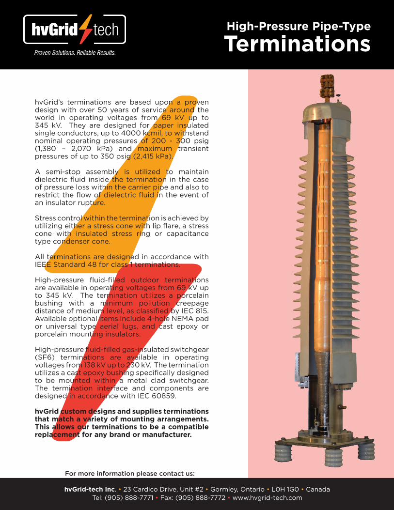
hvGrid’s terminations are based upon a proven design with over 50 years of service around the world in operating voltages from 69 kV up to 345 kV. They are designed for paper insulated single conductors, up to 4000 kcmil, to withstand nominal operating pressures of 200 - 300 psig (1,380 – 2,070 kPa) and maximum transient pressures of up to 350 psig (2,415 kPa).
A semi-stop assembly is utilized to maintain dielectric fl uid inside the termination in the case of pressure loss within the carrier pipe and also to restrict the fl ow of dielectric fl uid in the event of an insulator rupture.
Stress control within the termination is achieved by utilizing either a stress cone with lip fl are, a stress cone with insulated stress ring or capacitance type condenser cone.
All terminations are designed in accordance with IEEE Standard 48 for class 1 terminations.
High-pressure fl uid-fi lled outdoor terminations are available in operating voltages from 69 kV up to 345 kV. The termination utilizes a porcelain bushing with a minimum pollution creepage distance of medium level, as classifi ed by IEC 815. Available optional items include 4-hole NEMA pad or universal type aerial lugs, and cast epoxy or porcelain mounting insulators.
High-pressure fl uid-fi lled gas-insulated switchgear (SF6) terminations are available in operating voltages from 138 kV up to 230 kV. The termination utilizes a cast epoxy bushing specifi cally designed to be mounted within a metal clad switchgear. The termination interface and components are designed in accordance with IEC 60859.
hvGrid custom designs and supplies terminations that match a variety of mounting arrangements. This allows our terminations to be a compatible replacement for any brand or manufacturer.
For more information please contact us:
hvGrid-tech Inc. • 23 Cardico Drive, Unit #2 • Gormley, Ontario • L0H 1G0 • CanadaTel: (905) 888-7771 • Fax: (905) 888-7772 • www.hvgrid-tech.com
High-Pressure Pipe-Type
Terminations

hvGrid’s single conductor low-pressure fl uid-fi lled normal joints are based upon a proven design with over 50 years of service around the world in operating voltages from 69 kV up to 345 kV. The normal joints are installed in metallic casings that permit dielectric fl uid to fl ow from one cable section to another through the hollow core inserts of the connector. They can be designed for sectionalized or non-sectionalized applications.
Sectionalized joints utilize a cast epoxy joint sleeve insulator to isolate the cable sheaths on each side of the joint. This allows for sheath interruptions or permits sheath cross-bonding which minimizes sheath losses during cable operations.
Non-sectionalized joints are used when sheath continuity is preferred for solid grounding requirements.
The joint casing can be custom designed to meet the specifi c requirements of the cable system, taking into account the cable, sheath grounding, oil-feeding, manhole or joint bay confi guration.
The joints are designed for paper insulated single conductors, up to 4000 kcmil, to withstand nominal operating pressures of 100 psig (690 kPa) and maximum transient pressures of up to 150 psig (1035 kPa).
Normal joints are designed in accordance with IEEE Standard 404.
For more information please contact us:
hvGrid-tech Inc. • 23 Cardico Drive, Unit #2 • Gormley, Ontario • L0H 1G0 • CanadaTel: (905) 888-7771 • Fax: (905) 888-7772 • www.hvgrid-tech.com
Low-Pressure Fluid-Filled
Normal Joints

hvGrid’s three conductor high-pressure fl uid-fi lled normal joints are based upon a proven design with over 50 years of service around the world in operating voltages from 69 kV up to 345 kV. They are installed in steel pipe sleeves between carrier pipe sections or inside spreaderheads or trifurcators which are installed to separate the three phases into individual riser pipes leading to the terminations.
The steel pipe sleeves, which are welded to the carrier pipe through reducer fl anges, can consist of a double sleeve or multiple telescoping sleeves. The pipe sleeves and reducer fl anges can be custom designed to meet the specifi c requirements of the cable system, taking into account the cable, carrier pipe, oil-feeding, manhole or joint bay confi guration.
Aluminum spacers (spiders) are installed to separate the three shielded cores and to counter the adverse affects of thermo mechanical fl exing of the cable/joint interface.
The joints are designed for three paper insulated single conductors, up to 4000 kcmil, to withstand nominal operating pressures of 200 - 300 psig (1,380 – 2,070 kPa) and maximum transient pressures of up to 350 psig (2,415 kPa).
Normal joints are designed in accordance with IEEE Standard 404.
For more information please contact us:
hvGrid-tech Inc. • 23 Cardico Drive, Unit #2 • Gormley, Ontario • L0H 1G0 • CanadaTel: (905) 888-7771 • Fax: (905) 888-7772 • www.hvgrid-tech.com
High-Pressure Pipe-Type
Joints

hvGrid’s pre-pressurized “AC” type oil reservoirs are based upon a proven design with over 50 years of service around the world. The pre-pressurized reservoirs permit a positive fl uid pressure to be maintained along a cable circuit under extreme operating conditions.
Fluid feeding is accomplished through the use of nitrogen pressurized cells, surrounded by cable insulating fl uid within the tank. The pressure/volume characteristics of the reservoir are determined by the amount of gas in the cells and the pressurization level. The size and pressure setting of the reservoir is determined by the cable system parameters.
Pre-pressurized reservoirs can be installed at ground level which eliminates the need for any type of tower structure or elevation differences that are required for gravity feed oil reservoir systems.
All the valves and fi ttings are located on the outer shell for ease of making oil connections and for maintenance. An optional pressure gauge and mounting plate can be located on the outside of the reservoir for easy visibility and accessibility.
The reservoir’s outer shell can be fabricated from either mild steel or stainless steel and coated with grey epoxy resin paint. The stainless steel shells are recommended for corrosive situations such as coastal or industrial environments, manhole installations and for direct buried applications.
For more information please contact us:
hvGrid-tech Inc. • 23 Cardico Drive, Unit #2 • Gormley, Ontario • L0H 1G0 • CanadaTel: (905) 888-7771 • Fax: (905) 888-7772 • www.hvgrid-tech.com
Pre-pressurized “AC” Type
Oil Reservoirs
Outer Material: Mild Steel or Type 304 Stainless SteelOverall Maximum Diameter: ø27-1/4” (ø692 mm)
Size Nominal Gas Volume
Working Fluid Volume*
Height Weight (with oil)
EHV-30 140 L (37 gal) 50 L (13 gal) 43” (1092 mm) 240 lb (109 kg)
EHV-40 190 L (50 gal) 70 L (18 gal) 54” (1372 mm) 650 lb (295 kg)
EHV-50 235 L (62 gal) 90 L (24 gal) 66” (1676 mm) 875 lb (397 kg)
EHV-60 280 L (74 gal) 120 L (32 gal) 77” (1956 mm) 950 lb (431 kg)
EHV-70 330 L (87 gal) 150 L (40 gal) 89” (2260 mm) 1175 lb (533 kg)* estimates only (US gal)

Three phase direct grounding boxes with disconnecting links are used in conjunction with terminations and splices to ground the cable sheath.
Three phase grounding boxes with surge arrestor protection are used in conjunction with terminations and splices to protect the cable sheath from transient voltage build-up and from over-voltages arising from lightning strikes or switching surges.
Three phase cross-bonding boxes with surge arrestor protection are used to minimize sheath loses and to protect the cable sheath from over-voltages arising from lightning strikes or switching surges.
Specialty four phase grounding boxes are available for integrating a spare fourth phase. This is convenient in the event of a failure in one of the existing primary phases since it would be already connected into the existing system bonding scheme.
The boxes provide an easily accessible shield break location that can be used for system testing purposes.
The boxes are suitable for outdoor and underground environments. They can be direct buried or mounted vertically or horizontally, in a pit, vault, manhole or on a support structure. The cover incorporates a seamless foam-in-place gasket and a window to facilitate visual internal component inspections without removing the cover. The cable entrances are sealed with rubber grommet compression glands and heat-shrink sleeves.
Material: Type 304 Stainless SteelFabrication: Continuously welded seams and ground smooth; bolt-on cover with lifting handlesBonding Leads: Suitable for 4/0 to 500 kcmil insulated single conductor cablesSurge Arresters (standard): 3.0 kV, 3.6 kV, 4.8 kV and 6.0 kV Other voltage sizes available upon requestWeight: 90 lb (41 kg) approx.Dimensions: 21” (534mm) x 24” (610”) x 13-5/8” (346mm)Electrical: 25 kV DC withstand for 1 minute without arresters 15 kV AC withstand for 5 minutes at 60 Hz 47.5 kV BILMechanical: NEMA Type 6P rated enclosure (submersible) IEC 529 Protection Class IP68 (7 m depth)Arrestors: Nominal discharge current (8/20µs) = 10 kA peak Impulse withstand current (4/10µs) = 100 kA peak Long duration current impulse (2000µs) = 250 A
For more information please contact us:
hvGrid-tech Inc. • 23 Cardico Drive, Unit #2 • Gormley, Ontario • L0H 1G0 • CanadaTel: (905) 888-7771 • Fax: (905) 888-7772 • www.hvgrid-tech.com
Submersible
Grounding Boxes
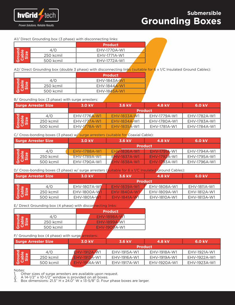
A1/ Direct Grounding box (3 phase) with disconnecting links:
Product
Gro
und
C
able
Si
ze
4/0 EHV-1770A-W1250 kcmil EHV-1771A-W1500 kcmil EHV-1772A-W1
A2/ Direct Grounding box (double 3 phase) with disconnecting links (suitable for 6 x 1/C Insulated Ground Cables):
Product
Gro
und
C
able
Si
ze
4/0 EHV-1843A-W1250 kcmil EHV-1844A-W1500 kcmil EHV-1845A-W1
B/ Grounding box (3 phase) with surge arresters:
Surge Arrester Size 3.0 kV 3.6 kV 4.8 kV 6.0 kVProduct
Gro
und
C
able
Si
ze
4/0 EHV-1776A-W1 EHV-1833A-W1 EHV-1779A-W1 EHV-1782A-W1250 kcmil EHV-1777A-W1 EHV-1834A-W1 EHV-1780A-W1 EHV-1783A-W1500 kcmil EHV-1778A-W1 EHV-1835A-W1 EHV-1781A-W1 EHV-1784A-W1
C/ Cross-bonding boxes (3 phase) w/ surge arresters (suitable for Coaxial Cable):
Surge Arrester Size 3.0 kV 3.6 kV 4.8 kV 6.0 kVProduct
Gro
und
C
able
Si
ze
4/0 EHV–1788A-W1 EHV-1836A-W1 EHV-1791A-W1 EHV-1794A-W1250 kcmil EHV-1789A-W1 EHV-1837A-W1 EHV-1792A-W1 EHV-1795A-W1500 kcmil EHV-1790A-W1 EHV-1838A-W1 EHV-1793A-W1 EHV-1796A-W1
D/ Cross-bonding boxes (3 phase) w/ surge arresters (suitable for 6 x 1/C Insulated Ground Cables):
Surge Arrester Size 3.0 kV 3.6 kV 4.8 kV 6.0 kVProduct
Gro
und
C
able
Si
ze
4/0 EHV-1807A-W1 EHV-1839A-W1 EHV-1808A-W1 EHV-1811A-W1250 kcmil EHV-1800A-W1 EHV-1840A-W1 EHV-1809A-W1 EHV-1812A-W1500 kcmil EHV-1801A-W1 EHV-1841A-W1 EHV-1810A-W1 EHV-1813A-W1
E/ Direct Grounding box (4 phase) with disconnecting links:
Product
Gro
und
C
able
Si
ze
4/0 EHV-1898A-W1250 kcmil EHV-1899A-W1500 kcmil EHV-1900A-W1
F/ Grounding box (4 phase) with surge arresters:
Surge Arrester Size 3.0 kV 3.6 kV 4.8 kV 6.0 kVProduct
Gro
und
C
able
Si
ze
4/0 EHV-1912A-W1 EHV-1915A-W1 EHV-1918A-W1 EHV-1921A-W1250 kcmil EHV-1913A-W1 EHV-1916A-W1 EHV-1919A-W1 EHV-1922A-W1500 kcmil EHV-1914A-W1 EHV-1917A-W1 EHV-1920A-W1 EHV-1923A-W1
Notes:1. Other sizes of surge arresters are available upon request.2. A 14-1/2” x 10-1/2” window is provided on all boxes. 3. Box dimensions: 21.5” H x 24.0” W x 13-5/8” D. Four phase boxes are larger.
Submersible
Grounding Boxes

Single phase direct grounding boxes with disconnecting link are used in conjunction with terminations to ground the cable sheath.
Single phase grounding boxes with surge arrestor protection are used in conjunction with terminations to protect the cable sheath from transient voltage build-up and from over-voltages arising from lightning strikes or switching surges.
Three phase direct grounding boxes with disconnecting links are used in conjunction with terminations and splices to ground the cable sheath.
Three phase grounding boxes with surge arrestor protection are used in conjunction with terminations and splices to protect the
cable sheath from transient voltage build-up and from over-voltages arising from lightning strikes or switching surges.
Specialty four phase grounding boxes are available for integrating a spare fourth phase. This is convenient in the event of a failure in one of the existing primary phases since it would be already connected into the existing system bonding scheme. The boxes provide an easily accessible shield break location that can be used for system testing purposes.
The boxes are suitable for indoor or outdoor environments. They can be mounted vertically or horizontally on a support structure. The cover incorporates a seamless foam-in-place gasket.
Material: Type 304 Stainless SteelFabrication: Continuously welded seams and ground smooth Hinged cover with locking haspBonding Leads: Suitable for 4/0 to 500 kcmil insulated single conductor cablesSurge Arresters (standard): 3.0 kV, 3.6 kV, 4.8 kV and 6.0 kV Other voltage sizes available upon requestMechanical: NEMA Type 4X rated enclosure (water tight / dust tight)Arrestors: Nominal discharge current (8/20µs) = 10 kA peak Impulse withstand current (4/10µs) = 100 kA peak Long duration current impulse (2000µs) = 250 A
For more information please contact us:
hvGrid-tech Inc. • 23 Cardico Drive, Unit #2 • Gormley, Ontario • L0H 1G0 • CanadaTel: (905) 888-7771 • Fax: (905) 888-7772 • www.hvgrid-tech.com
Non-Submersible
Grounding Boxes
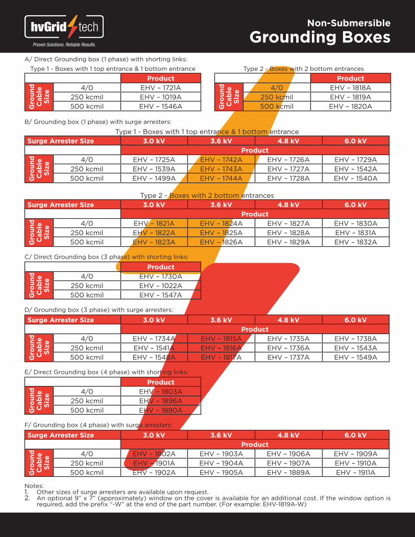
A/ Direct Grounding box (1 phase) with shorting links:
Type 1 - Boxes with 1 top entrance & 1 bottom entrance Type 2 - Boxes with 2 bottom entrances
Product Product
Gro
und
C
able
Si
ze
4/0 EHV – 1721A
Gro
und
C
able
Si
ze
4/0 EHV – 1818A250 kcmil EHV – 1019A 250 kcmil EHV – 1819A500 kcmil EHV – 1546A 500 kcmil EHV – 1820A
B/ Grounding box (1 phase) with surge arresters:
Type 1 - Boxes with 1 top entrance & 1 bottom entranceSurge Arrester Size 3.0 kV 3.6 kV 4.8 kV 6.0 kV
Product
Gro
und
C
able
Si
ze
4/0 EHV – 1725A EHV – 1742A EHV – 1726A EHV – 1729A250 kcmil EHV – 1539A EHV – 1743A EHV – 1727A EHV – 1542A500 kcmil EHV – 1499A EHV – 1744A EHV – 1728A EHV – 1540A
Type 2 - Boxes with 2 bottom entrancesSurge Arrester Size 3.0 kV 3.6 kV 4.8 kV 6.0 kV
Product
Gro
und
C
able
Si
ze
4/0 EHV – 1821A EHV – 1824A EHV – 1827A EHV – 1830A250 kcmil EHV – 1822A EHV – 1825A EHV – 1828A EHV – 1831A500 kcmil EHV – 1823A EHV – 1826A EHV – 1829A EHV – 1832A
C/ Direct Grounding box (3 phase) with shorting links:
Product
Gro
und
C
able
Si
ze
4/0 EHV – 1730A250 kcmil EHV – 1022A500 kcmil EHV – 1547A
D/ Grounding box (3 phase) with surge arresters:
Surge Arrester Size 3.0 kV 3.6 kV 4.8 kV 6.0 kVProduct
Gro
und
C
able
Si
ze
4/0 EHV – 1734A EHV – 1815A EHV – 1735A EHV – 1738A250 kcmil EHV – 1541A EHV – 1816A EHV – 1736A EHV – 1543A500 kcmil EHV – 1548A EHV – 1817A EHV – 1737A EHV – 1549A
E/ Direct Grounding box (4 phase) with shorting links:
Product
Gro
und
C
able
Si
ze
4/0 EHV – 1803A250 kcmil EHV – 1896A500 kcmil EHV – 1890A
F/ Grounding box (4 phase) with surge arresters:
Surge Arrester Size 3.0 kV 3.6 kV 4.8 kV 6.0 kVProduct
Gro
und
C
able
Si
ze
4/0 EHV – 1802A EHV – 1903A EHV – 1906A EHV – 1909A250 kcmil EHV – 1901A EHV – 1904A EHV – 1907A EHV – 1910A500 kcmil EHV – 1902A EHV – 1905A EHV – 1889A EHV – 1911A
Notes:1. Other sizes of surge arresters are available upon request.2. An optional 9” x 7” (approximately) window on the cover is available for an additional cost. If the window option is
required, add the prefi x “-W” at the end of the part number. (For example: EHV-1819A-W)
Non-Submersible
Grounding Boxes

Cable clamps can be used for LPOF, XLPE, and EPR cables. Typical installation applications include: vertical shaft, termination support, riser pole, tunnel, seismic, manhole/duct entrance, cable tray, and wind towers. Custom clampling solutions are also available for non-standard / special applications.
Cast aluminum clamps are available in fi ve different cable diameter ranges. Each clamp is supplied with stainless steel mounting bolts and neoprene liners. Optional stainless steel springs are available to allow for expansion and contraction of the cable, while maintaining adequate holding force to secure the cable.
Other specialty types of clamps can be custom designed to suit the customer’s specifi c cable dimensions and/or special installation requirements. Examples include single point mounted clamps and multi-cable clamps.
Single point mounted clamps allow clamping in positions where two perpendicular holes to the cable direction are diffi cult to maintain or are not possible (for example, snaking of the cable).
Multi-cable clamps allow more than one cable to be clamped together in the same orientation utilizing only one clamp.
hvGrid-tech Inc. is the North American distributor of ID-Technik fi berglass reinforced cable clamps which are available in a variety of different styles for various cable applications. These clamps are ultraviolet ray protected, fl ame resistant and free from halogens. Mounting hardware, neoprene liners and springs are all optional items.
For more information please contact us:
hvGrid-tech Inc. • 23 Cardico Drive, Unit #2 • Gormley, Ontario • L0H 1G0 • CanadaTel: (905) 888-7771 • Fax: (905) 888-7772 • www.hvgrid-tech.com
Cable Clamps
Product Cable Range
EHV-1279A Item 0 1.97” – 2.95”(50mm – 75mm)
EHV-1279A Item 1 2.95” – 3.94”(75mm – 100mm)
EHV-1279A Item 2 3.94” – 4.72”(100mm – 120mm)
EHV-1279A Item 3 4.72” – 5.31”(120mm – 135mm)
EHV-1279A Item 4 5.31” – 5.90”(135mm – 150mm)

hvGrid-tech Inc. • 23 Cardico Drive, Unit #2 • Gormley, Ontario • L0H 1G0 • Canada Tel: (905) 888-7771 • Fax: (905) 888-7772 • www.hvgrid-tech.com