Embed Size (px)
Citation preview
In wood-frame buildings of three or more stories, cumulative shrinkage can be significant and have an impact on the function and performance of finishes, openings, mechanical/electrical/plumbing (MEP) systems, and structural connections. However, as more designers look to wood-frame construction to improve the cost and sustainability of their mid-rise projects, many have learned that accommodating wood shrinkage is actually very straightforward.
Wood is hygroscopic, meaning it has the ability to absorb and release moisture. As this occurs, it also has the potential to change dimensionally. Knowing how and where wood shrinks and swells helps designers detail their buildings to minimize related effects.
Wood shrinkage occurs perpendicular to grain, meaning that a solid sawn wood stud or floor joist will shrink in its cross-section dimensions (width and depth). Longitudinal shrinkage is negligible, meaning the length of a stud or floor joist will essentially remain unchanged. In multi-story buildings, wood shrinkage is therefore concentrated at the wall plates, floor and roof joists, and rim boards. Depending on the materials and details used at floor-to-wall and roof-to-wall intersections, shrinkage in light-frame wood construction can range from 0.05 inches to 0.5 inches per level.
This publication will describe procedures for estimating wood shrinkage and provide detailing options that minimize its effects on building performance.
Wood Science & ShrinkageUnderstanding the cellular structure of wood allows us to understand how moisture and wood interact and identify the paths that moisture typically travels. Within wood, moisture is present in two forms: (1) free water in cell cavities, and (2) bound water in cell walls. Simplistically, wood’s cellular structure can be imagined as a bundle of drinking straws held together with a rubber band, with each straw representing
Accommodating Shrinkage in Multi-Story Wood-Frame StructuresRichard McLain, MS, PE, SE, Senior Technical Director – Tall Wood, WoodWorks • Doug Steimle, PE, Principal, Schaefer
a longitudinal cell in the wood. Water can be free water stored in the straw cavity or bound water absorbed by the straw walls. At high moisture contents, water exists in both locations. As the wood dries, the free water is released from the cell cavities before the bound water is released from the cell walls. When wood has no free water and yet the cell wall is still saturated, it is said to be at its fiber saturation point (FSP). Imagine a sponge that has just been taken out of a bucket filled with water. As the sponge is lifted from the bucket, water comes out of the pores. When the sponge is squeezed, more water comes out of the pores. The moment when no water can be squeezed out of the sponge but yet it still feels damp is analogous to the FSP. The moisture retained in the sponge is the bound water and water that has been squeezed out is the free water.
The Brooklyn Riverside
Jacksonville, Florida
Architect: Dwell Design Studio
Structural Engineer: M2 Structural Engineering
Photo: Pollack Shores, Matrix Residential
$FRA_634_Shrinkage-SolutionPaper.indd 1 5/30/19 10:39 AM
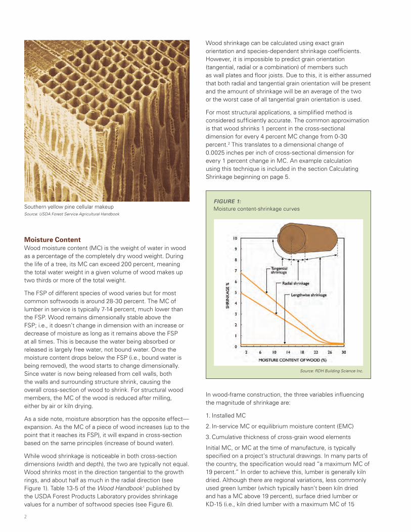
Moisture ContentWood moisture content (MC) is the weight of water in wood as a percentage of the completely dry wood weight. During the life of a tree, its MC can exceed 200 percent, meaning the total water weight in a given volume of wood makes up two thirds or more of the total weight.
The FSP of different species of wood varies but for most common softwoods is around 28-30 percent. The MC of lumber in service is typically 7-14 percent, much lower than the FSP. Wood remains dimensionally stable above the FSP; i.e., it doesn’t change in dimension with an increase or decrease of moisture as long as it remains above the FSP at all times. This is because the water being absorbed or released is largely free water, not bound water. Once the moisture content drops below the FSP (i.e., bound water is being removed), the wood starts to change dimensionally. Since water is now being released from cell walls, both the walls and surrounding structure shrink, causing the overall cross-section of wood to shrink. For structural wood members, the MC of the wood is reduced after milling, either by air or kiln drying.
As a side note, moisture absorption has the opposite effect—expansion. As the MC of a piece of wood increases (up to the point that it reaches its FSP), it will expand in cross-section based on the same principles (increase of bound water).
While wood shrinkage is noticeable in both cross-section dimensions (width and depth), the two are typically not equal. Wood shrinks most in the direction tangential to the growth rings, and about half as much in the radial direction (see Figure 1). Table 13-5 of the Wood Handbook1 published by the USDA Forest Products Laboratory provides shrinkage values for a number of softwood species (see Figure 6).
Wood shrinkage can be calculated using exact grain orientation and species-dependent shrinkage coefficients. However, it is impossible to predict grain orientation (tangential, radial or a combination) of members such as wall plates and floor joists. Due to this, it is either assumed that both radial and tangential grain orientation will be present and the amount of shrinkage will be an average of the two or the worst case of all tangential grain orientation is used.
For most structural applications, a simplified method is considered sufficiently accurate. The common approximation is that wood shrinks 1 percent in the cross-sectional dimension for every 4 percent MC change from 0-30 percent.2 This translates to a dimensional change of 0.0025 inches per inch of cross-sectional dimension for every 1 percent change in MC. An example calculation using this technique is included in the section Calculating Shrinkage beginning on page 5.
In wood-frame construction, the three variables influencing the magnitude of shrinkage are:
1. Installed MC
2. In-service MC or equilibrium moisture content (EMC)
3. Cumulative thickness of cross-grain wood elements
Initial MC, or MC at the time of manufacture, is typically specified on a project’s structural drawings. In many parts of the country, the specification would read “a maximum MC of 19 percent.” In order to achieve this, lumber is generally kiln dried. Although there are regional variations, less commonly used green lumber (which typically hasn’t been kiln dried and has a MC above 19 percent), surface dried lumber or KD-15 (i.e., kiln dried lumber with a maximum MC of 15
FIGURE 1:Moisture content-shrinkage curvesSouthern yellow pine cellular makeup
Source: USDA Forest Service Agricultural Handbook
Source: RDH Building Science Inc.
2
$FRA_634_Shrinkage-SolutionPaper.indd 2 5/30/19 10:39 AM
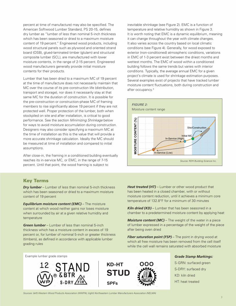
inevitable shrinkage (see Figure 2). EMC is a function of temperature and relative humidity as shown in Figure 3. It is worth noting that EMC is a dynamic equilibrium, meaning it can change throughout the year with climate changes. It also varies across the country based on local climatic conditions (see Figure 4). Generally, for wood exposed to exterior (non-conditioned) atmospheric conditions, variations in EMC of 1-3 percent exist between the driest months and wettest months. The EMC of wood within a conditioned building follows the same trends but varies with interior conditions. Typically, the average annual EMC for a given project’s climate is used for shrinkage estimation purposes. Several examples exist of projects that have tracked lumber moisture content fluctuations, both during construction and after occupancy.3
FIGURE 2:Moisture content range
Key TermsDry lumber – Lumber of less than nominal 5-inch thickness which has been seasoned or dried to a maximum moisture content of 19 percent
Equilibrium moisture content (EMC) – The moisture content at which wood neither gains nor loses moisture when surrounded by air at a given relative humidity and temperature
Green lumber – Lumber of less than nominal 5-inch thickness which has a moisture content in excess of 19 percent or, for lumber of nominal 5-inch or greater thickness (timbers), as defined in accordance with applicable lumber grading rules
Sources: (left) Western Wood Products Association (WWPA); (right) Northeastern Lumber Manufacturers Association (NELMA)
percent at time of manufacture) may also be specified. The American Softwood Lumber Standard, PS 20-15, defines dry lumber as “lumber of less than nominal 5-inch thickness which has been seasoned or dried to a maximum moisture content of 19 percent.” Engineered wood products, including wood structural panels such as plywood and oriented strand board (OSB), glued-laminated timber (glulam) and structural composite lumber (SCL), are manufactured with lower moisture contents, in the range of 2-15 percent. Engineered wood manufacturers generally provide initial moisture contents for their products.
Lumber that has been dried to a maximum MC of 19 percent at the time of manufacture does not necessarily maintain that MC over the course of its pre-construction life (distribution, transport and storage), nor does it necessarily stay at that same MC for the duration of construction. It is possible for the pre-construction or construction-phase MC of framing members to rise significantly above 19 percent if they are not protected well. Proper protection of the lumber, both when stockpiled on site and after installation, is critical to good performance. See the section Minimizing Shrinkage below for ways to avoid moisture accumulation during construction. Designers may also consider specifying a maximum MC at the time of installation as this is the value that will provide a more accurate shrinkage calculation. Ideally the MC should be measured at time of installation and compared to initial assumptions.
After close-in, the framing in a conditioned building eventually reaches its in-service MC, or EMC, in the range of 7-15 percent. Until that point, the wood framing is subject to
Grade Stamp Markings:
S-GRN: surfaced green
S-DRY: surfaced dry
KD: kiln dried
HT: heat treated
Heat treated (HT) – Lumber or other wood product that has been heated in a closed chamber, with or without moisture content reduction, until it achieves a minimum core temperature of 132.8°F for a minimum of 30 minutes
Kiln dried (KD) – Lumber that has been seasoned in a chamber to a predetermined moisture content by applying heat
Moisture content (MC) – The weight of the water in a piece of lumber expressed in a percentage of the weight of the piece after being oven dried
Fiber saturation point (FSP) – The point in drying wood at which all free moisture has been removed from the cell itself while the cell wall remains saturated with absorbed moisture
Source: RDH Building Science Inc.
Site/Construction
In-Service (High)Initial MC
In-Service (Low)MO
ISTU
RE
CO
NTE
NT
(%)
Example lumber grade stamps
KD-HT
STUDSPFs
3
$FRA_634_Shrinkage-SolutionPaper.indd 3 5/30/19 10:39 AM
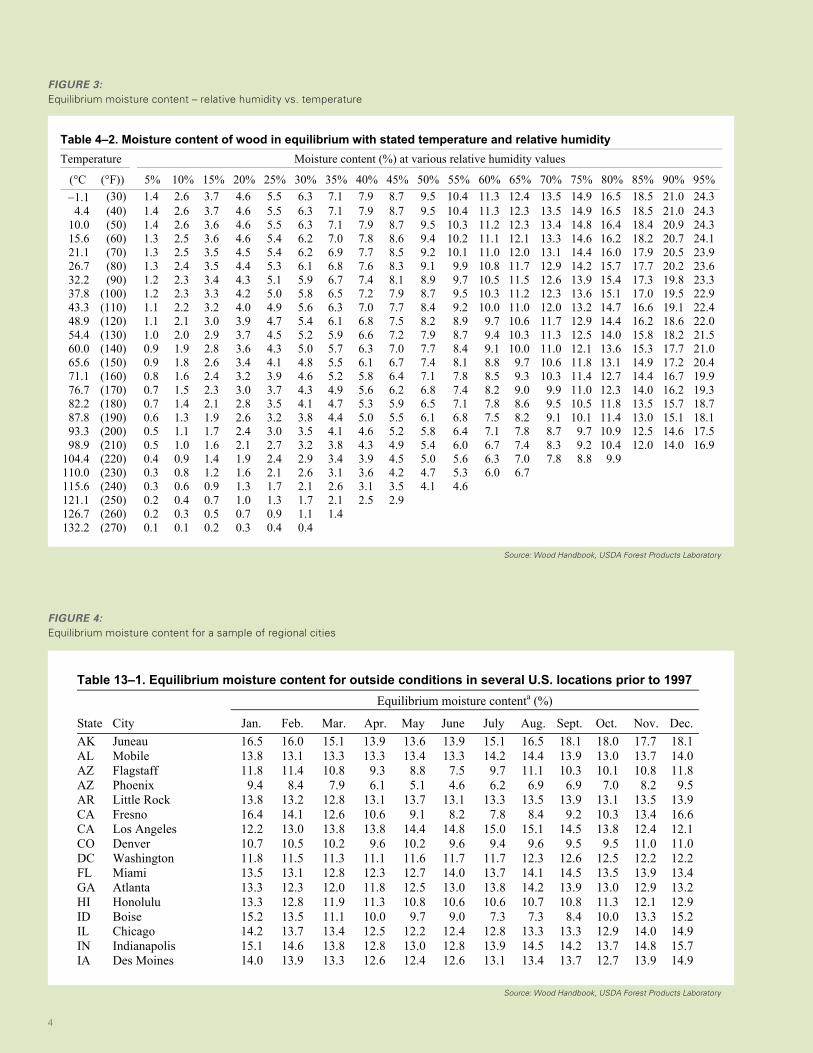
FIGURE 3: Equilibrium moisture content – relative humidity vs. temperature
4–4
for resorption (adsorption) is lower than for desorption. The ratio of adsorption EMC to desorption EMC varies with species, RH, and temperature, with a mean value of about 0.8 near room temperature (Stamm 1964, Skaar 1988). EMC values in Table 4–2 were derived primarily for Sitka spruce under conditions described as oscillating vapor pressure desorption (Stamm and Loughborough 1935), which was shown to represent a condition midway between adsorption and desorption. The tabulated EMC values thus provide a suitable and practical compromise for use when the direc-tion of sorption is not always known.
Liquid Water AbsorptionWood products in service may be exposed to liquid water through a variety of mechanisms. Contact with liquid water can induce rapid changes in the moisture content of wood, in contrast to the slow changes that occur due to water va-por sorption. In addition, liquid water absorption can bring the moisture content of wood above fiber saturation (water vapor sorption alone cannot). As wood absorbs water above its fiber saturation point, air in the cell lumina is replaced by water. Absorption of liquid water may continue until the maximum moisture content is reached.
The mechanism of water absorption is called capillary ac-tion or wicking. Water interacts strongly with the wood cell wall and forms a concave meniscus (curved surface) within the lumen. This interaction combined with the water–air
surface tension creates a pressure that draws water up the lumina.
The rate of liquid water absorption in wood depends on several factors. The rate of absorption is most rapid in the longitudinal direction (that is, when the transverse section or end grain is exposed to water). The rate at which air can es-cape from wood affects water absorption, as water displaces air in the lumina. Chapter 16 discusses the ability of surface finishes such as water repellents to inhibit water absorption.
International Standard ISO 15148 (ISO 2002) describes a method for measuring the rate of water absorption. One sur-face of a specimen is partially immersed in water. To limit absorption to this one surface and restrict moisture transport to one dimension, the sides of the specimen are coated with a water- and vapor-tight sealant. The specimen is periodi-cally removed, surfaces are blotted, and the specimen is weighed and again partially immersed in the water. The mass of water absorbed per unit area of specimen surface is plotted against the square root of time. The initial part of the curve is usually linear, and the slope of this linear portion is the water absorption coefficient Aw (kg m–2 s–1/2). Measured values of Aw for softwoods are in the range 10–16 g m–2 s–1/2 in the longitudinal direction and 1–7 g m–2 s–1/2 in the transverse directions (IEA 1991; Kumaran 1999, 2002).
The liquid water diffusivity Dw (m2 s–1) is a measure of the rate of moisture flow (kg m–2 s–1) through a material
Table 4–2. Moisture content of wood in equilibrium with stated temperature and relative humidityTemperature Moisture content (%) at various relative humidity values
(°C (°F)) 5% 10% 15% 20% 25% 30% 35% 40% 45% 50% 55% 60% 65% 70% 75% 80% 85% 90% 95%1.1 (30) 1.4 2.6 3.7 4.6 5.5 6.3 7.1 7.9 8.7 9.5 10.4 11.3 12.4 13.5 14.9 16.5 18.5 21.0 24.3
4.4 (40) 1.4 2.6 3.7 4.6 5.5 6.3 7.1 7.9 8.7 9.5 10.4 11.3 12.3 13.5 14.9 16.5 18.5 21.0 24.310.0 (50) 1.4 2.6 3.6 4.6 5.5 6.3 7.1 7.9 8.7 9.5 10.3 11.2 12.3 13.4 14.8 16.4 18.4 20.9 24.315.6 (60) 1.3 2.5 3.6 4.6 5.4 6.2 7.0 7.8 8.6 9.4 10.2 11.1 12.1 13.3 14.6 16.2 18.2 20.7 24.121.1 (70) 1.3 2.5 3.5 4.5 5.4 6.2 6.9 7.7 8.5 9.2 10.1 11.0 12.0 13.1 14.4 16.0 17.9 20.5 23.926.7 (80) 1.3 2.4 3.5 4.4 5.3 6.1 6.8 7.6 8.3 9.1 9.9 10.8 11.7 12.9 14.2 15.7 17.7 20.2 23.632.2 (90) 1.2 2.3 3.4 4.3 5.1 5.9 6.7 7.4 8.1 8.9 9.7 10.5 11.5 12.6 13.9 15.4 17.3 19.8 23.337.8 (100) 1.2 2.3 3.3 4.2 5.0 5.8 6.5 7.2 7.9 8.7 9.5 10.3 11.2 12.3 13.6 15.1 17.0 19.5 22.943.3 (110) 1.1 2.2 3.2 4.0 4.9 5.6 6.3 7.0 7.7 8.4 9.2 10.0 11.0 12.0 13.2 14.7 16.6 19.1 22.448.9 (120) 1.1 2.1 3.0 3.9 4.7 5.4 6.1 6.8 7.5 8.2 8.9 9.7 10.6 11.7 12.9 14.4 16.2 18.6 22.054.4 (130) 1.0 2.0 2.9 3.7 4.5 5.2 5.9 6.6 7.2 7.9 8.7 9.4 10.3 11.3 12.5 14.0 15.8 18.2 21.560.0 (140) 0.9 1.9 2.8 3.6 4.3 5.0 5.7 6.3 7.0 7.7 8.4 9.1 10.0 11.0 12.1 13.6 15.3 17.7 21.065.6 (150) 0.9 1.8 2.6 3.4 4.1 4.8 5.5 6.1 6.7 7.4 8.1 8.8 9.7 10.6 11.8 13.1 14.9 17.2 20.471.1 (160) 0.8 1.6 2.4 3.2 3.9 4.6 5.2 5.8 6.4 7.1 7.8 8.5 9.3 10.3 11.4 12.7 14.4 16.7 19.976.7 (170) 0.7 1.5 2.3 3.0 3.7 4.3 4.9 5.6 6.2 6.8 7.4 8.2 9.0 9.9 11.0 12.3 14.0 16.2 19.382.2 (180) 0.7 1.4 2.1 2.8 3.5 4.1 4.7 5.3 5.9 6.5 7.1 7.8 8.6 9.5 10.5 11.8 13.5 15.7 18.787.8 (190) 0.6 1.3 1.9 2.6 3.2 3.8 4.4 5.0 5.5 6.1 6.8 7.5 8.2 9.1 10.1 11.4 13.0 15.1 18.193.3 (200) 0.5 1.1 1.7 2.4 3.0 3.5 4.1 4.6 5.2 5.8 6.4 7.1 7.8 8.7 9.7 10.9 12.5 14.6 17.598.9 (210) 0.5 1.0 1.6 2.1 2.7 3.2 3.8 4.3 4.9 5.4 6.0 6.7 7.4 8.3 9.2 10.4 12.0 14.0 16.9
104.4 (220) 0.4 0.9 1.4 1.9 2.4 2.9 3.4 3.9 4.5 5.0 5.6 6.3 7.0 7.8 8.8 9.9 110.0 (230) 0.3 0.8 1.2 1.6 2.1 2.6 3.1 3.6 4.2 4.7 5.3 6.0 6.7 115.6 (240) 0.3 0.6 0.9 1.3 1.7 2.1 2.6 3.1 3.5 4.1 4.6 121.1 (250) 0.2 0.4 0.7 1.0 1.3 1.7 2.1 2.5 2.9 126.7 (260) 0.2 0.3 0.5 0.7 0.9 1.1 1.4 132.2 (270) 0.1 0.1 0.2 0.3 0.4 0.4
General Technical Report FPL–GTR–190
13–4
General Technical Report FPL–GTR–190
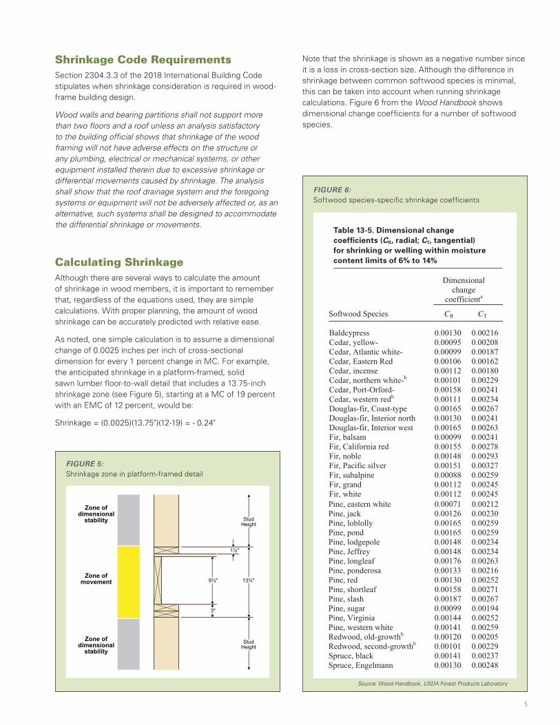
Table 13–1. Equilibrium moisture content for outside conditions in several U.S. locations prior to 1997Equilibrium moisture contenta (%)
State City Jan. Feb. Mar. Apr. May June July Aug. Sept. Oct. Nov. Dec.AK Juneau 16.5 16.0 15.1 13.9 13.6 13.9 15.1 16.5 18.1 18.0 17.7 18.1AL Mobile 13.8 13.1 13.3 13.3 13.4 13.3 14.2 14.4 13.9 13.0 13.7 14.0AZ Flagstaff 11.8 11.4 10.8 9.3 8.8 7.5 9.7 11.1 10.3 10.1 10.8 11.8AZ Phoenix 9.4 8.4 7.9 6.1 5.1 4.6 6.2 6.9 6.9 7.0 8.2 9.5AR Little Rock 13.8 13.2 12.8 13.1 13.7 13.1 13.3 13.5 13.9 13.1 13.5 13.9CA Fresno 16.4 14.1 12.6 10.6 9.1 8.2 7.8 8.4 9.2 10.3 13.4 16.6CA Los Angeles 12.2 13.0 13.8 13.8 14.4 14.8 15.0 15.1 14.5 13.8 12.4 12.1CO Denver 10.7 10.5 10.2 9.6 10.2 9.6 9.4 9.6 9.5 9.5 11.0 11.0DC Washington 11.8 11.5 11.3 11.1 11.6 11.7 11.7 12.3 12.6 12.5 12.2 12.2FL Miami 13.5 13.1 12.8 12.3 12.7 14.0 13.7 14.1 14.5 13.5 13.9 13.4GA Atlanta 13.3 12.3 12.0 11.8 12.5 13.0 13.8 14.2 13.9 13.0 12.9 13.2HI Honolulu 13.3 12.8 11.9 11.3 10.8 10.6 10.6 10.7 10.8 11.3 12.1 12.9ID Boise 15.2 13.5 11.1 10.0 9.7 9.0 7.3 7.3 8.4 10.0 13.3 15.2IL Chicago 14.2 13.7 13.4 12.5 12.2 12.4 12.8 13.3 13.3 12.9 14.0 14.9IN Indianapolis 15.1 14.6 13.8 12.8 13.0 12.8 13.9 14.5 14.2 13.7 14.8 15.7IA Des Moines 14.0 13.9 13.3 12.6 12.4 12.6 13.1 13.4 13.7 12.7 13.9 14.9KS Wichita 13.8 13.4 12.4 12.4 13.2 12.5 11.5 11.8 12.6 12.4 13.2 13.9KY Louisville 13.7 13.3 12.6 12.0 12.8 13.0 13.3 13.7 14.1 13.3 13.5 13.9LA New Orleans 14.9 14.3 14.0 14.2 14.1 14.6 15.2 15.3 14.8 14.0 14.2 15.0ME Portland 13.1 12.7 12.7 12.1 12.6 13.0 13.0 13.4 13.9 13.8 14.0 13.5MA Boston 11.8 11.6 11.9 11.7 12.2 12.1 11.9 12.5 13.1 12.8 12.6 12.2MI Detroit 14.7 14.1 13.5 12.6 12.3 12.3 12.6 13.3 13.7 13.5 14.4 15.1MN Minneapolis–St. Paul 13.7 13.6 13.3 12.0 11.9 12.3 12.5 13.2 13.8 13.3 14.3 14.6MS Jackson 15.1 14.4 13.7 13.8 14.1 13.9 14.6 14.6 14.6 14.1 14.3 14.9MO St. Louis 14.5 14.1 13.2 12.4 12.8 12.6 12.9 13.3 13.7 13.1 14.0 14.9MT Missoula 16.7 15.1 12.8 11.4 11.6 11.7 10.1 9.8 11.3 12.9 16.2 17.6NE Omaha 14.0 13.8 13.0 12.1 12.6 12.9 13.3 13.8 14.0 13.0 13.9 14.8NV Las Vegas 8.5 7.7 7.0 5.5 5.0 4.0 4.5 5.2 5.3 5.9 7.2 8.4NV Reno 12.3 10.7 9.7 8.8 8.8 8.2 7.7 7.9 8.4 9.4 10.9 12.3NM Albuquerque 10.4 9.3 8.0 6.9 6.8 6.4 8.0 8.9 8.7 8.6 9.6 10.7NY New York 12.2 11.9 11.5 11.0 11.5 11.8 11.8 12.4 12.6 12.3 12.5 12.3NC Raleigh 12.8 12.1 12.2 11.7 13.1 13.4 13.8 14.5 14.5 13.7 12.9 12.8ND Fargo 14.2 14.6 15.2 12.9 11.9 12.9 13.2 13.2 13.7 13.5 15.2 15.2OH Cleveland 14.6 14.2 13.7 12.6 12.7 12.7 12.8 13.7 13.8 13.3 13.8 14.6OK Oklahoma City 13.2 12.9 12.2 12.1 13.4 13.1 11.7 11.8 12.9 12.3 12.8 13.2OR Pendleton 15.8 14.0 11.6 10.6 9.9 9.1 7.4 7.7 8.8 11.0 14.6 16.5OR Portland 16.5 15.3 14.2 13.5 13.1 12.4 11.7 11.9 12.6 15.0 16.8 17.4PA Philadelphia 12.6 11.9 11.7 11.2 11.8 11.9 12.1 12.4 13.0 13.0 12.7 12.7SC Charleston 13.3 12.6 12.5 12.4 12.8 13.5 14.1 14.6 14.5 13.7 13.2 13.2SD Sioux Falls 14.2 14.6 14.2 12.9 12.6 12.8 12.6 13.3 13.6 13.0 14.6 15.3TN Memphis 13.8 13.1 12.4 12.2 12.7 12.8 13.0 13.1 13.2 12.5 12.9 13.6TX Dallas–Ft. Worth 13.6 13.1 12.9 13.2 13.9 13.0 11.6 11.7 12.9 12.8 13.1 13.5TX El Paso 9.6 8.2 7.0 5.8 6.1 6.3 8.3 9.1 9.3 8.8 9.0 9.8UT Salt Lake City 14.6 13.2 11.1 10.0 9.4 8.2 7.1 7.4 8.5 10.3 12.8 14.9VA Richmond 13.2 12.5 12.0 11.3 12.1 12.4 13.0 13.7 13.8 13.5 12.8 13.0WA Seattle–Tacoma 15.6 14.6 15.4 13.7 13.0 12.7 12.2 12.5 13.5 15.3 16.3 16.5WI Madison 14.5 14.3 14.1 12.8 12.5 12.8 13.4 14.4 14.9 14.1 15.2 15.7WV Charleston 13.7 13.0 12.1 11.4 12.5 13.3 14.1 14.3 14.0 13.6 13.0 13.5WY Cheyenne 10.2 10.4 10.7 10.4 10.8 10.5 9.9 9.9 9.7 9.7 10.6 10.6aEMC values were determined from the average of 30 or more years of relative humidity and temperature data available from the National Climatic Data Center of the National Oceanic and Atmospheric Administration.
FIGURE 4: Equilibrium moisture content for a sample of regional cities
Source: Wood Handbook, USDA Forest Products Laboratory
Source: Wood Handbook, USDA Forest Products Laboratory
4
$FRA_634_Shrinkage-SolutionPaper.indd 4 5/30/19 10:39 AM
Shrinkage Code RequirementsSection 2304.3.3 of the 2018 International Building Code stipulates when shrinkage consideration is required in wood-frame building design.
Wood walls and bearing partitions shall not support more than two floors and a roof unless an analysis satisfactory to the building official shows that shrinkage of the wood framing will not have adverse effects on the structure or any plumbing, electrical or mechanical systems, or other equipment installed therein due to excessive shrinkage or differential movements caused by shrinkage. The analysis shall show that the roof drainage system and the foregoing systems or equipment will not be adversely affected or, as an alternative, such systems shall be designed to accommodate the differential shrinkage or movements.
Calculating ShrinkageAlthough there are several ways to calculate the amount of shrinkage in wood members, it is important to remember that, regardless of the equations used, they are simple calculations. With proper planning, the amount of wood shrinkage can be accurately predicted with relative ease.
As noted, one simple calculation is to assume a dimensional change of 0.0025 inches per inch of cross-sectional dimension for every 1 percent change in MC. For example, the anticipated shrinkage in a platform-framed, solid sawn lumber floor-to-wall detail that includes a 13.75-inch shrinkage zone (see Figure 5), starting at a MC of 19 percent with an EMC of 12 percent, would be:
Shrinkage = (0.0025)(13.75")(12-19) = - 0.24"
FIGURE 5: Shrinkage zone in platform-framed detail
13¾"
StudHeight
StudHeight
Zone ofdimensional
stability
Zone ofdimensional
stability
Zone ofmovement 9¼"
1½"
3"
Note that the shrinkage is shown as a negative number since it is a loss in cross-section size. Although the difference in shrinkage between common softwood species is minimal, this can be taken into account when running shrinkage calculations. Figure 6 from the Wood Handbook shows dimensional change coefficients for a number of softwood species.
FIGURE 6: Softwood species-specific shrinkage coefficients
Table 13-5. Dimensional change coefficients (CR, radial; CT, tangential) for shrinking or welling within moisture content limits of 6% to 14%
Source: Wood Handbook, USDA Forest Products Laboratory
Table 13–5. Dimensional change coefficients (CR, radial; CT, tangential) for shrinking or swelling within moisture content limits of 6% to 14%
Dimensionalchange
coefficienta
Softwood Species CR CT
Baldcypress 0.00130 0.00216Cedar, yellow- 0.00095 0.00208Cedar, Atlantic white- 0.00099 0.00187Cedar, Eastern Red 0.00106 0.00162Cedar, incense 0.00112 0.00180Cedar, northern white-b 0.00101 0.00229Cedar, Port-Orford- 0.00158 0.00241Cedar, western redb 0.00111 0.00234Douglas-fir, Coast-type 0.00165 0.00267Douglas-fir, Interior north 0.00130 0.00241Douglas-fir, Interior west 0.00165 0.00263Fir, balsam 0.00099 0.00241Fir, California red 0.00155 0.00278Fir, noble 0.00148 0.00293Fir, Pacific silver 0.00151 0.00327Fir, subalpine 0.00088 0.00259Fir, grand 0.00112 0.00245Fir, white 0.00112 0.00245Pine, eastern white Pine, jack Pine, loblolly Pine, pond Pine, lodgepole Pine, Jeffrey Pine, longleaf Pine, ponderosa Pine, red Pine, shortleaf Pine, slash Pine, sugar Pine, Virginia Pine, western white Redwood, old-growthb Redwood, second-growthb Spruce, black Spruce, Engelmann
0.000710.001260.001650.001650.001480.001480.001760.001330.001300.001580.001870.000990.001440.001410.001200.001010.001410.00130
0.00212 0.00230 0.00259 0.00259 0.00234 0.00234 0.00263 0.00216 0.00252 0.00271 0.00267 0.00194 0.00252 0.00259 0.00205 0.00229 0.00237 0.00248
5
$FRA_634_Shrinkage-SolutionPaper.indd 5 5/30/19 10:39 AM
The equation for wood shrinkage utilizing these coefficients is as follows:
S = C*Di*(MF-Mi)
Where:
S = Shrinkage
C = Dimensional change coefficient (from the Wood Handbook; conservatively, the worst case of CT is typically used)
Di = Cross-sectional dimension of wood subject to shrinkage (shrinkage zone)
MF = Final wood MC
Mi = Initial wood MC
Using the example above, for a longleaf pine (southern pine) member, CT = 0.00263 and shrinkage is:
S = (0.00263)(13.75")(12-19) = - 0.25"
The result when accounting for the species-specific coefficient is similar to the simplified calculation above. Several free shrinkage calculators can also be found online.
When utilizing other types of floor joists such as I-Joists and parallel chord trusses, a degree of engineering judgement is required to determine what to include in the shrinkage zone. For example, floor sheathing is often manufactured with a low moisture content that could be near or even below the EMC. The same could be true for I-Joists. There is also a possibility that these materials slightly expand as they take on moisture during construction, only to shrink again after the building is closed in. Although the final determination should take into account how well the framing materials are protected from the weather during construction, some engineers choose not to include these members in the shrinkage zone—i.e., they expect no shrinkage contribution from them. For parallel chord trusses in a platform-framed condition, only the top and bottom chords are typically included in the shrinkage zone. This is due to the fact that a vertically-oriented member usually exists at the end of the truss, separating the top and bottom chords, and no longitudinal shrinkage is assumed in this member.
Although this paper is dedicated to accommodating shrinkage of wood
products due to loss of moisture, wood products also have the ability to
increase in moisture content and expand in cross-section. This typically
occurs during construction as the wood framing may be completed
several months before building enclosure systems are installed and
made functional. Under these temporary moisture increase conditions,
it is important to consider the potential for temporary expansion of wood
framing products, particularly panel products such as wall, floor and roof
sheathing which may be installed to cover a large expanse in the same
plane (e.g., large floor plate or wall elevation).
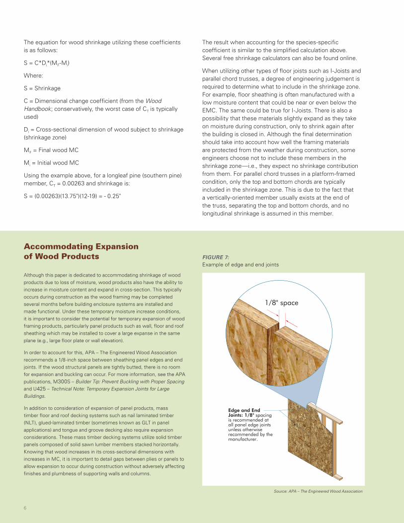
In order to account for this, APA – The Engineered Wood Association
recommends a 1/8-inch space between sheathing panel edges and end
joints. If the wood structural panels are tightly butted, there is no room
for expansion and buckling can occur. For more information, see the APA
publications, M300S – Builder Tip: Prevent Buckling with Proper Spacing
and U425 – Technical Note: Temporary Expansion Joints for Large
Buildings.
In addition to consideration of expansion of panel products, mass
timber floor and roof decking systems such as nail laminated timber
(NLT), glued-laminated timber (sometimes known as GLT in panel
applications) and tongue and groove decking also require expansion
considerations. These mass timber decking systems utilize solid timber
panels composed of solid sawn lumber members stacked horizontally.
Knowing that wood increases in its cross-sectional dimensions with
increases in MC, it is important to detail gaps between plies or panels to
allow expansion to occur during construction without adversely affecting
finishes and plumbness of supporting walls and columns.
Accommodating Expansion of Wood Products FIGURE 7:
Example of edge and end joints
Edge and End Joints: 1/8" spacing is recommended at all panel edge joints unless otherwise recommended by the manufacturer.
FIGURE 1
EXAMPLE OF EDGE AND END JOINTS
1/8" space
Source: APA – The Engineered Wood Association
6
$FRA_634_Shrinkage-SolutionPaper.indd 6 5/30/19 10:39 AM
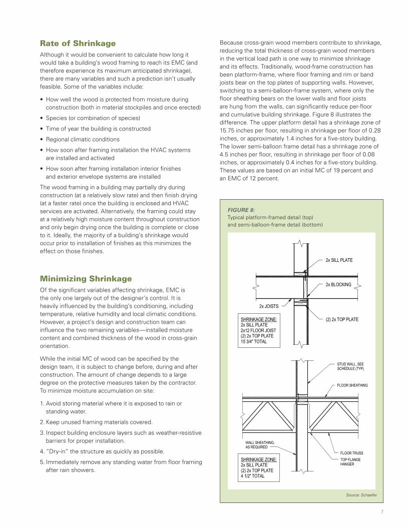
FIGURE 8:Typical platform-framed detail (top) and semi-balloon-frame detail (bottom)
Source: Schaefer
Rate of ShrinkageAlthough it would be convenient to calculate how long it would take a building’s wood framing to reach its EMC (and therefore experience its maximum anticipated shrinkage), there are many variables and such a prediction isn’t usually feasible. Some of the variables include:
• How well the wood is protected from moisture during construction (both in material stockpiles and once erected)
• Species (or combination of species)
• Time of year the building is constructed
• Regional climatic conditions
• How soon after framing installation the HVAC systems are installed and activated
• How soon after framing installation interior finishes and exterior envelope systems are installed
The wood framing in a building may partially dry during construction (at a relatively slow rate) and then finish drying (at a faster rate) once the building is enclosed and HVAC services are activated. Alternatively, the framing could stay at a relatively high moisture content throughout construction and only begin drying once the building is complete or close to it. Ideally, the majority of a building’s shrinkage would occur prior to installation of finishes as this minimizes the effect on those finishes.
Minimizing ShrinkageOf the significant variables affecting shrinkage, EMC is the only one largely out of the designer’s control. It is heavily influenced by the building’s conditioning, including temperature, relative humidity and local climatic conditions. However, a project’s design and construction team can influence the two remaining variables—installed moisture content and combined thickness of the wood in cross-grain orientation.
While the initial MC of wood can be specified by the design team, it is subject to change before, during and after construction. The amount of change depends to a large degree on the protective measures taken by the contractor. To minimize moisture accumulation on site:
1. Avoid storing material where it is exposed to rain or standing water.
2. Keep unused framing materials covered.
3. Inspect building enclosure layers such as weather-resistive barriers for proper installation.
4. “Dry-in” the structure as quickly as possible.
5. Immediately remove any standing water from floor framing after rain showers.
Because cross-grain wood members contribute to shrinkage, reducing the total thickness of cross-grain wood members in the vertical load path is one way to minimize shrinkage and its effects. Traditionally, wood-frame construction has been platform-frame, where floor framing and rim or band joists bear on the top plates of supporting walls. However, switching to a semi-balloon-frame system, where only the floor sheathing bears on the lower walls and floor joists are hung from the walls, can significantly reduce per-floor and cumulative building shrinkage. Figure 8 illustrates the difference. The upper platform detail has a shrinkage zone of 15.75 inches per floor, resulting in shrinkage per floor of 0.28 inches, or approximately 1.4 inches for a five-story building. The lower semi-balloon frame detail has a shrinkage zone of 4.5 inches per floor, resulting in shrinkage per floor of 0.08 inches, or approximately 0.4 inches for a five-story building. These values are based on an initial MC of 19 percent and an EMC of 12 percent.
2x SILL PLATE
2x BLOCKING
(2) 2x TOP PLATESHRINKAGE ZONE:2x SILL PLATE2x12 FLOOR JOIST(2) 2x TOP PLATE15 3/4" TOTAL
2x JOISTS
FLOOR TRUSS
STUD WALL, SEESCHEDULE (TYP)
T/SHEATHINGSEE PLAN
FLOOR SHEATHING
TOP FLANGEHANGER
WALL SHEATHING,AS REQUIRED
SHRINKAGE ZONE:2x SILL PLATE(2) 2x TOP PLATE4 1/2" TOTAL
FLOOR TRUSS
STUD WALL, SEESCHEDULE (TYP)
T/SHEATHINGSEE PLAN
FLOOR SHEATHING
TOP FLANGEHANGER
WALL SHEATHING,AS REQUIRED
SHRINKAGE ZONE:2x SILL PLATE(2) 2x TOP PLATE4 1/2" TOTAL
7
$FRA_634_Shrinkage-SolutionPaper.indd 7 5/30/19 10:39 AM
In modern multi-story heavy or mass timber buildings where column and beam structural framing systems are used, detailing the column-to-floor deck and beam connections should include shrinkage consideration.
One option consists of an upper column bearing directly on the mass timber deck, which bears directly on the support beam and lower column. This is the equivalent of the platform-frame detail described above; because the shrinkage zone per floor is relatively deep, shrinkage per floor is at the higher end of the expected range. In a multi-story building, this per floor shrinkage accumulates and can exceed 1 inch overall.
An alternate detailing strategy that minimizes accumulated shrinkage involves column-to-beam connections that isolate the upper column from bearing on the decking and support beam. Detailing strategies involve either notching the column to allow the beam to bear on a shelf or creating a vertical load path where columns above bear directly on columns below.
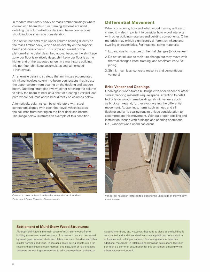
Alternatively, columns can be single-story with steel connectors aligned with each floor level, which isolates the columns from bearing on the floor deck and beams. The image below illustrates an example of this condition.
Column to column isolation detail at mass timber floor deckPhoto: Alex Schreyer, University of Massachusetts
Differential MovementWhen considering how and when wood framing is likely to shrink, it is also important to consider how wood interacts with other building materials and building components. Other materials may exhibit significantly different shrinkage and swelling characteristics. For instance, some materials:
1. Expand due to moisture or thermal changes (brick veneer)
2. Do not shrink due to moisture change but may move with thermal changes (steel framing, and steel/cast iron/PVC piping)
3. Shrink much less (concrete masonry and cementitious veneers)
Brick Veneer and OpeningsOpenings in wood-frame buildings with brick veneer or other similar cladding materials require special attention to detail. Not only do wood-frame buildings shrink, veneers such as brick can expand, further exaggerating the differential movement. At openings, items such as head and sill flashing and jamb sealing require unique consideration to accommodate this movement. Without proper detailing and installation, issues with drainage and opening operations (i.e., window won’t open) can occur.
Although shrinkage is the main cause of multi-story wood-frame
building movement, small amounts of movement can also be caused
by small gaps between studs and plates, studs and headers and other
similar framing conditions. These gaps occur during construction for
reasons that include uneven member end cuts, lack of fully engaged
fasteners connecting one member to adjacent members, twisting or
warping members, etc. However, they tend to close as the building is
constructed and additional dead loads are applied prior to installation
of finishes and building occupancy. Some engineers include this
additional movement in total building shrinkage calculations (1/8-inch
per floor is a common assumption for this settlement amount) while
others choose to ignore it.
Veneer sill has been installed too close to the underside of the windowPhoto: Schaefer
Settlement of Multi-Story Wood Structures:
8
$FRA_634_Shrinkage-SolutionPaper.indd 8 5/30/19 10:39 AM
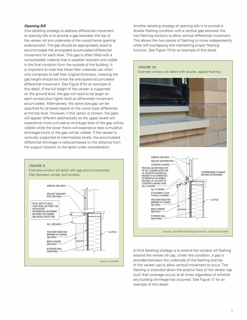
FIGURE 9:Example window sill detail with gap and compressible filler between veneer and window
Source: Schaefer
Opening SillOne detailing strategy to address differential movement at opening sills is to provide a gap between the top of the veneer sill and underside of the wood-frame opening extension/sill. The gap should be appropriately sized to accommodate the anticipated accumulated differential movement for each level. This gap is often filled with a compressible material that is weather resistant and visible in the final condition from the outside of the building. It is important to note that these filler materials can often only compress to half their original thickness, meaning the gap height should be twice the anticipated accumulated differential movement. See Figure 9 for an example of this detail. If the full height of the veneer is supported on the ground level, the gap will need to be larger on each consecutive higher level as differential movement accumulates. Alternatively, the same size gap can be specified for all levels based on the worst case differential at the top level. However, if this option is chosen, the gaps will appear different aesthetically as the upper levels will experience more cumulative shrinkage (less of the gap will be visible) while the lower floors will experience less cumulative shrinkage (more of the gap will be visible). If the veneer is vertically supported at intermediate levels, the accumulated differential shrinkage is reduced based on the distance from the support location to the detail under consideration.
NOTE: SIZE OF CAULKJOINT SHALL BE TWICE THEANTICIPATEDDIFFERENTIAL MOVEMENTBETWEEN THE VENEERAND WOOD STRUCTURE
SEALANT & BACKERROD, SEE ARCH
SILL, SEE ARCH
BRICK VENEER,SEE ARCH
WEATHER RESISTANTBARRIER & FLASHING,SEE ARCH
EXTERIOR WALLSHEATHING
WINDOW, SEE ARCH
2x STUD
Another detailing strategy at opening sills is to provide a double flashing condition with a vertical gap between the two flashing sections to allow vertical differential movement. This allows the two pieces of flashing to move independently while still overlapping and maintaining proper flashing function. See Figure 10 for an example of this detail.
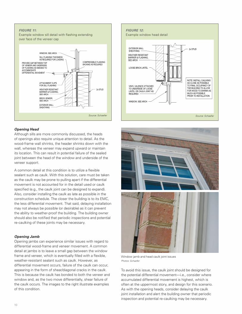
A third detailing strategy is to extend the window sill flashing beyond the veneer sill cap. Under this condition, a gap is provided between the underside of the flashing and top of the veneer cap to allow vertical movement to occur. The flashing is extended down the exterior face of the veneer cap such that coverage occurs at all times regardless of whether any building shrinkage has occurred. See Figure 11 for an example of this detail.
FIGURE 10:Example window sill detail with double, lapped flashing
Sources: (top) RDH Building Science Inc.; (bottom) Schaefer
BRICK VENEER,SEE ARCH
WEATHER RESISTANTBARRIER & FLASHING,SEE ARCH
EXTERIOR WALLSHEATHING
WINDOW, SEE ARCH
2x STUD
PROVIDE GAP BETWEEN TOPOF SILL FLASHING & BOTTOMOF COUNTER FLASHING ASNEEDED TO ACCOMMODATEDIFFERENTIAL MOVEMENT.PROVIDE 1/2" LAP JOINT OFCOUNTER FLASHING OVERSILL FLASHING
COMPRESSIBLE FLASHINGBACKING AS REQUIRED
SILL FLASHINGATTACHMENT CLIPSFOR SILL FLASHING
COUNTER FLASHINGSEALANT & BACKER ROD
9
$FRA_634_Shrinkage-SolutionPaper.indd 9 5/30/19 10:39 AM
Window jamb and head caulk joint issuesPhotos: Schaefer
FIGURE 11:Example window sill detail with flashing extending over face of the veneer cap
Source: Schaefer
BRICK VENEER,SEE ARCH
WEATHER RESISTANTBARRIER & FLASHING,SEE ARCH
EXTERIOR WALLSHEATHING
WINDOW, SEE ARCH
2x STUD
PROVIDE GAP BETWEEN TOPOF VENEER AND UNDERSIDEOF FLASHING AS NEEDED TOACCOMMODATEDIFFERENTIAL MOVEMENT
COMPRESSIBLE FLASHINGBACKING AS REQUIRED
SILL FLASHING THICKNESSAS REQUIRED FOR LOADING
ATTACHMENT CLIPSFOR SILL FLASHING
FIGURE 12:Example window head detail
Source: Schaefer
WINDOW, SEE ARCH
VINYL VALENCE ATTACHEDTO UNDERSIDE OF LOOSELINTEL OR CAULK JOINT ASREQUIRED
LOOSE BRICK LINTEL
WEATHER RESISTANTBARRIER & FLASHING,SEE ARCH
EXTERIOR WALLSHEATHING
2x STUD
NOTE: INSTALL CAULKINGAS CLOSE AS POSSIBLETO FINAL OCCUPANCY OFTHE BUILDING TO ALLOWFOR WOOD TO SHRINK ASMUCH AS POSSIBLEPRIOR TO INSTALLATION
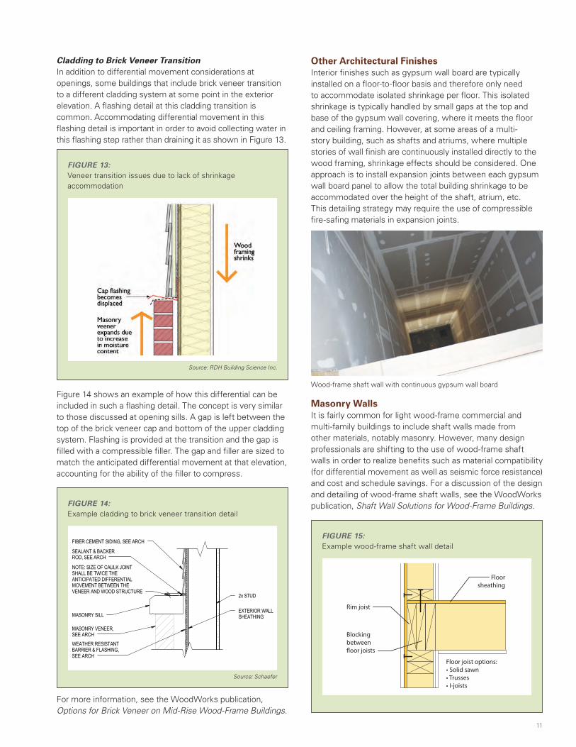
Opening JambOpening jambs can experience similar issues with regard to differential wood-frame and veneer movement. A common detail at jambs is to leave a small gap between the window frame and veneer, which is eventually filled with a flexible, weather-resistant sealant such as caulk. However, as differential movement occurs, failure of the caulk can occur, appearing in the form of shear/diagonal cracks in the caulk. This is because the caulk has bonded to both the veneer and window and, as the two move differentially, shear failure of the caulk occurs. The images to the right illustrate examples of this condition.
Opening HeadAlthough sills are more commonly discussed, the heads of openings also require unique attention to detail. As the wood-frame wall shrinks, the header shrinks down with the wall, whereas the veneer may expand upward or maintain its location. This can result in potential failure of the sealed joint between the head of the window and underside of the veneer support.
A common detail at this condition is to utilize a flexible sealant such as caulk. With this solution, care must be taken as the caulk may be prone to pulling apart if the differential movement is not accounted for in the detail used or caulk specified (e.g., the caulk joint can be designed to expand). Also, consider installing the caulk as late as possible in the construction schedule. The closer the building is to its EMC, the less differential movement. That said, delaying installation may not always be possible (or desirable) as it can prevent the ability to weather-proof the building. The building owner should also be notified that periodic inspections and potential re-caulking of these joints may be necessary.
To avoid this issue, the caulk joint should be designed for the potential differential movement—i.e., consider where accumulated differential movement is highest, which is often at the uppermost story, and design for this scenario. As with the opening heads, consider delaying the caulk joint installation and alert the building owner that periodic inspection and potential re-caulking may be necessary.
10
$FRA_634_Shrinkage-SolutionPaper.indd 10 5/30/19 10:39 AM
Cladding to Brick Veneer TransitionIn addition to differential movement considerations at openings, some buildings that include brick veneer transition to a different cladding system at some point in the exterior elevation. A flashing detail at this cladding transition is common. Accommodating differential movement in this flashing detail is important in order to avoid collecting water in this flashing step rather than draining it as shown in Figure 13.
For more information, see the WoodWorks publication, Options for Brick Veneer on Mid-Rise Wood-Frame Buildings.
Figure 14 shows an example of how this differential can be included in such a flashing detail. The concept is very similar to those discussed at opening sills. A gap is left between the top of the brick veneer cap and bottom of the upper cladding system. Flashing is provided at the transition and the gap is filled with a compressible filler. The gap and filler are sized to match the anticipated differential movement at that elevation, accounting for the ability of the filler to compress.
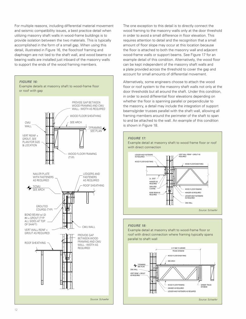
Other Architectural FinishesInterior finishes such as gypsum wall board are typically installed on a floor-to-floor basis and therefore only need to accommodate isolated shrinkage per floor. This isolated shrinkage is typically handled by small gaps at the top and base of the gypsum wall covering, where it meets the floor and ceiling framing. However, at some areas of a multi-story building, such as shafts and atriums, where multiple stories of wall finish are continuously installed directly to the wood framing, shrinkage effects should be considered. One approach is to install expansion joints between each gypsum wall board panel to allow the total building shrinkage to be accommodated over the height of the shaft, atrium, etc. This detailing strategy may require the use of compressible fire-safing materials in expansion joints.
FIGURE 13:Veneer transition issues due to lack of shrinkage accommodation
Source: RDH Building Science Inc.
FIGURE 14:Example cladding to brick veneer transition detail
Source: Schaefer
MASONRY VENEER,SEE ARCH
MASONRY SILL
NOTE: SIZE OF CAULK JOINTSHALL BE TWICE THEANTICIPATED DIFFERENTIALMOVEMENT BETWEEN THEVENEER AND WOOD STRUCTURE
FIBER CEMENT SIDING, SEE ARCH
2x STUD
EXTERIOR WALLSHEATHING
SEALANT & BACKERROD, SEE ARCH
WEATHER RESISTANTBARRIER & FLASHING,SEE ARCH
Wood-frame shaft wall with continuous gypsum wall board
Masonry WallsIt is fairly common for light wood-frame commercial and multi-family buildings to include shaft walls made from other materials, notably masonry. However, many design professionals are shifting to the use of wood-frame shaft walls in order to realize benefits such as material compatibility (for differential movement as well as seismic force resistance) and cost and schedule savings. For a discussion of the design and detailing of wood-frame shaft walls, see the WoodWorks publication, Shaft Wall Solutions for Wood-Frame Buildings.
FIGURE 15:Example wood-frame shaft wall detail
Floorsheathing
Floor joist options:• Solid sawn• Trusses• I-joists
Floor sheathing
Ledger for ceiling attachment
Floor sheathing Floor sheathing
Joist hanger
Blocking inshaft wallbetween studs
Attach ledger to studs withfasteners (wood screws, lag screws)designed toaccount for 1 layerof gypsum
Top �ange joist hangerapproved to span 2 layers GWB
Floor joist
Joist hanger
Floor beam
(2) 2x �at blocking between trusses
Specify truss web holdback toallow gypsum installation
Exterior Side Exterior Side
Wall plate elevationsshifted to intermediatelanding elevations atstair shafts
Masonry shaft wall
Floor framing andwood bearing walls
Top �ange joisthanger approved tospan 2 layers GWB
Consider “hinge” at wallplates for out-of-planewind & seismic loads due to lack of adjacent �oor:Install additional member(rim) to span horizontally
Attach ledger to eachshaftwall stud withfasteners designed toaccount for gypsum
Stair Shaft Side
OPTION 1 OPTION 2
Stair Shaft Side
Shaft wall
Intermediate stair landing
framing
Intermediate stair landing
framing
Shaft wall
Rim joist
Blocking between�oor joists
Ledger interruptsone layer of shaft
wall gypsum
Stair landingframing
Floor sheathing
2 Hr protectionprovided allaroundbeamvia. blocking
Beam bears directly on axially
loaded post
Extend wall gypsum to underside of sheathing between trusses
11
$FRA_634_Shrinkage-SolutionPaper.indd 11 5/30/19 10:39 AM
For multiple reasons, including differential material movement and seismic compatibility issues, a best practice detail when utilizing masonry shaft walls in wood-frame buildings is to provide isolation between the two materials. This is typically accomplished in the form of a small gap. When using this detail, illustrated in Figure 16, the floor/roof framing and diaphragm are not tied to the shaft wall, and wood beams or bearing walls are installed just inboard of the masonry walls to support the ends of the wood framing members.
The one exception to this detail is to directly connect the wood framing to the masonry walls only at the door threshold in order to avoid a small difference in floor elevation. This requires attention to detail and the recognition that a small amount of floor slope may occur at this location because the floor is attached to both the masonry wall and adjacent wood-frame walls or support beams. See Figure 17 for an example detail of this condition. Alternatively, the wood floor can be kept independent of the masonry shaft walls and a plate provided across the threshold to cover the gap and account for small amounts of differential movement.
Alternatively, some engineers choose to attach the wood floor or roof system to the masonry shaft walls not only at the door thresholds but all around the shaft. Under this condition, in order to avoid differential floor elevations depending on whether the floor is spanning parallel or perpendicular to the masonry, a detail may include the integration of support beams/girder trusses parallel with the shaft wall, allowing all framing members around the perimeter of the shaft to span to and be attached to the wall. An example of this condition is shown in Figure 18.
FIGURE 18:Example detail at masonry shaft to wood-frame floor or roof with direct connection where framing typically spans parallel to shaft wall
Source: Schaefer
T/FRAMINGSEE PLAN
WOOD FLOOR SHEATHING
WOOD FLOOR FRAMING
CMU WALL
VERT REINF + GROUTAS REQUIRED
LEDGER AND FASTENERS AS REQUIRED
SEE ARCH
HANGER AS REQUIRED
GIRDER TRUSSOR BEAM
TRUSS OR BEAM4'-0" MIN TO GIRDER
FIGURE 17: Example detail at masonry shaft to wood frame floor or roof with direct connection
Source: Schaefer
T/SHEATHINGSEE PLAN
WOOD FLOOR SHEATHING
WOOD FLOOR FRAMING
VERT WALL REINF + GROUT ASREQUIRED
BOND BEAM ASREQUIRED
GROUTEDCOURSE
HANGER AS REQUIRED
LEDGER AND FASTENERSAS REQUIRED
2x JOIST
LEDGER AND FASTENERSAS REQUIRED
HANGER ASREQUIRED
WOOD FLOOR SHEATHING
CMU WALL
T/SHEATHINGSEE PLAN
WOOD FLOOR SHEATHING
WOOD FLOOR FRAMING
VERT WALL REINF + GROUT ASREQUIRED
BOND BEAM ASREQUIRED
GROUTEDCOURSE
HANGER AS REQUIRED
LEDGER AND FASTENERSAS REQUIRED
2x JOIST
LEDGER AND FASTENERSAS REQUIRED
HANGER ASREQUIRED
WOOD FLOOR SHEATHING
CMU WALL
FIGURE 16:Example details at masonry shaft to wood-frame floor or roof with gap
Source: Schaefer
BOND BEAM w/ (2)#4 + GROUT (TYPALL SIDES AT TOPOF SHAFT)
GROUTED COURSE (TYP)
ROOF SHEATHING
NAILER PLATE WITHFASTENERS AS REQUIRED
CMU WALL
LEDGER AND FASTENERSAS REQUIRED
VERT WALL REINF +GROUT AS REQUIRED
ROOF SHEATHINGWIDTH AS REQUIRED
PROVIDE GAP BETWEENWOOD FRAMING AND CMU WALL -
T/CMUSEE ARCH
NAILER PLATE WITH FASTENERS AS REQUIRED
LEDGERS AND FASTENERS AS REQUIRED
ROOF SHEATHING
GROUTED COURSE (TYP)
BOND BEAM w/ (2) #4 + GROUT (TYP ALL SIDES AT TOP OF SHAFT)
VERT WALL REINF +GROUT AS REQUIRED
ROOF SHEATHING
CMU WALL
PROVIDE GAP BETWEEN WOOD FRAMING AND CMU WALL - WIDTH AS REQUIRED
T/CMUSEE ARCH
T/FRAMINGSEE PLAN
WOOD FLOOR SHEATHING
WOOD FLOOR FRAMING(TYP)
CMU WALL
VERT REINF + GROUT,SEE PLAN FOR SIZE &LOCATION
WIDTH AS REQUIRED
PROVIDE GAP BETWEENWOOD FRAMING AND CMU WALL -
SEE ARCH CMU WALL
VERT REINF + GROUT, SEE PLAN FOR SIZE & LOCATION
WOOD FLOOR FRAMING(TYP)
PROVIDE GAP BETWEEN WOOD FRAMING AND CMU WALL - WIDTH AS REQUIRED
WOOD FLOOR SHEATHING
SEE ARCH
T/FRAMINGSEE PLAN
12
$FRA_634_Shrinkage-SolutionPaper.indd 12 5/30/19 10:39 AM
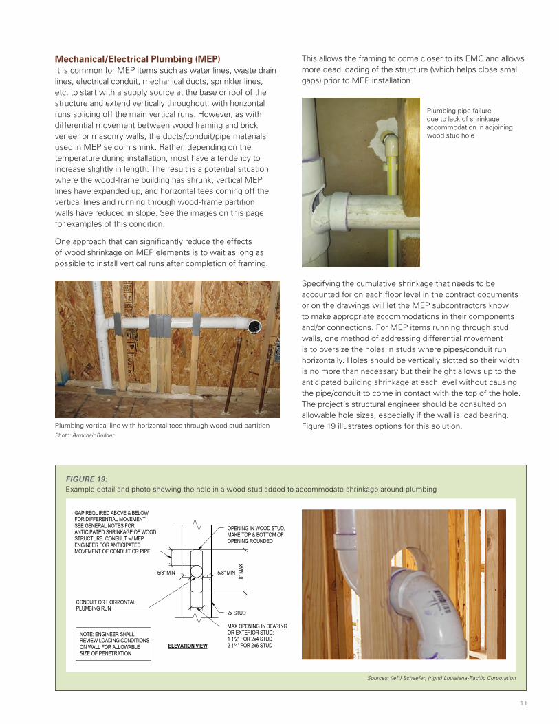
Specifying the cumulative shrinkage that needs to be accounted for on each floor level in the contract documents or on the drawings will let the MEP subcontractors know to make appropriate accommodations in their components and/or connections. For MEP items running through stud walls, one method of addressing differential movement is to oversize the holes in studs where pipes/conduit run horizontally. Holes should be vertically slotted so their width is no more than necessary but their height allows up to the anticipated building shrinkage at each level without causing the pipe/conduit to come in contact with the top of the hole. The project’s structural engineer should be consulted on allowable hole sizes, especially if the wall is load bearing. Figure 19 illustrates options for this solution.Plumbing vertical line with horizontal tees through wood stud partition
Photo: Armchair Builder
Plumbing pipe failure due to lack of shrinkage accommodation in adjoining wood stud hole
Mechanical/Electrical Plumbing (MEP)It is common for MEP items such as water lines, waste drain lines, electrical conduit, mechanical ducts, sprinkler lines, etc. to start with a supply source at the base or roof of the structure and extend vertically throughout, with horizontal runs splicing off the main vertical runs. However, as with differential movement between wood framing and brick veneer or masonry walls, the ducts/conduit/pipe materials used in MEP seldom shrink. Rather, depending on the temperature during installation, most have a tendency to increase slightly in length. The result is a potential situation where the wood-frame building has shrunk, vertical MEP lines have expanded up, and horizontal tees coming off the vertical lines and running through wood-frame partition walls have reduced in slope. See the images on this page for examples of this condition.
One approach that can significantly reduce the effects of wood shrinkage on MEP elements is to wait as long as possible to install vertical runs after completion of framing.
FIGURE 19: Example detail and photo showing the hole in a wood stud added to accommodate shrinkage around plumbing
5/8" MIN5/8" MIN
8" M
AX
MAX OPENING IN BEARINGOR EXTERIOR STUD:1 1/2" FOR 2x4 STUD2 1/4" FOR 2x6 STUD
2x STUD
OPENING IN WOOD STUD,MAKE TOP & BOTTOM OFOPENING ROUNDED
GAP REQUIRED ABOVE & BELOWFOR DIFFERENTIAL MOVEMENT,SEE GENERAL NOTES FORANTICIPATED SHRINKAGE OF WOODSTRUCTURE. CONSULT w/ MEPENGINEER FOR ANTICIPATEDMOVEMENT OF CONDUIT OR PIPE
CONDUIT OR HORIZONTALPLUMBING RUN
NOTE: ENGINEER SHALLREVIEW LOADING CONDITIONSON WALL FOR ALLOWABLESIZE OF PENETRATION
ELEVATION VIEW
Sources: (left) Schaefer; (right) Louisiana-Pacific Corporation
This allows the framing to come closer to its EMC and allows more dead loading of the structure (which helps close small gaps) prior to MEP installation.
13
$FRA_634_Shrinkage-SolutionPaper.indd 13 5/30/19 10:39 AM
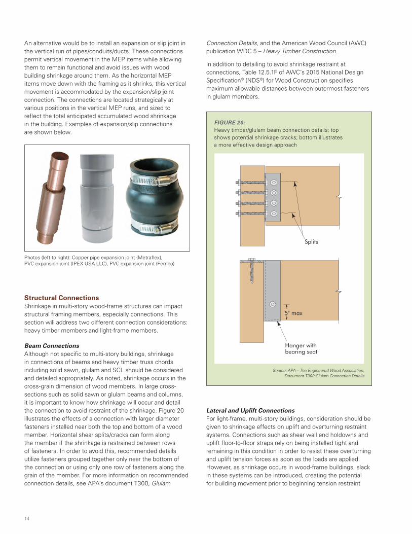
An alternative would be to install an expansion or slip joint in the vertical run of pipes/conduits/ducts. These connections permit vertical movement in the MEP items while allowing them to remain functional and avoid issues with wood building shrinkage around them. As the horizontal MEP items move down with the framing as it shrinks, this vertical movement is accommodated by the expansion/slip joint connection. The connections are located strategically at various positions in the vertical MEP runs, and sized to reflect the total anticipated accumulated wood shrinkage in the building. Examples of expansion/slip connections are shown below.
Photos (left to right): Copper pipe expansion joint (Metraflex), PVC expansion joint (IPEX USA LLC), PVC expansion joint (Fernco)
Structural ConnectionsShrinkage in multi-story wood-frame structures can impact structural framing members, especially connections. This section will address two different connection considerations: heavy timber members and light-frame members.
Beam ConnectionsAlthough not specific to multi-story buildings, shrinkage in connections of beams and heavy timber truss chords including solid sawn, glulam and SCL should be considered and detailed appropriately. As noted, shrinkage occurs in the cross-grain dimension of wood members. In large cross-sections such as solid sawn or glulam beams and columns, it is important to know how shrinkage will occur and detail the connection to avoid restraint of the shrinkage. Figure 20 illustrates the effects of a connection with larger diameter fasteners installed near both the top and bottom of a wood member. Horizontal shear splits/cracks can form along the member if the shrinkage is restrained between rows of fasteners. In order to avoid this, recommended details utilize fasteners grouped together only near the bottom of the connection or using only one row of fasteners along the grain of the member. For more information on recommended connection details, see APA’s document T300, Glulam
Connection Details, and the American Wood Council (AWC) publication WDC 5 – Heavy Timber Construction.
In addition to detailing to avoid shrinkage restraint at connections, Table 12.5.1F of AWC’s 2015 National Design Specification® (NDS®) for Wood Construction specifies maximum allowable distances between outermost fasteners in glulam members.
Lateral and Uplift ConnectionsFor light-frame, multi-story buildings, consideration should be given to shrinkage effects on uplift and overturning restraint systems. Connections such as shear wall end holdowns and uplift floor-to-floor straps rely on being installed tight and remaining in this condition in order to resist these overturning and uplift tension forces as soon as the loads are applied. However, as shrinkage occurs in wood-frame buildings, slack in these systems can be introduced, creating the potential for building movement prior to beginning tension restraint
FIGURE 20:Heavy timber/glulam beam connection details; top shows potential shrinkage cracks; bottom illustrates a more effective design approach
Source: APA – The Engineered Wood Association, Document T300 Glulam Connection Details
FIGURE 3A
BEAM-TO-BEAM CONNECTION
Correct Incorrect Result of Incorrect Detail
Clip angles with long rows of fasteners can cause splits to form in the suspended beam, as shown above, due to tension perpendicular-to-grain stresses induced at the bolts due to beam shrinkage. Use a hanger with bearing seat as shown.
SplitsClip angles
Hanger with bearing seat
5" max
14
$FRA_634_Shrinkage-SolutionPaper.indd 14 5/30/19 10:39 AM
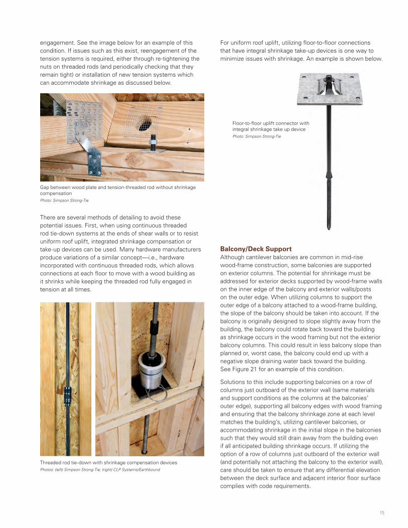
There are several methods of detailing to avoid these potential issues. First, when using continuous threaded rod tie-down systems at the ends of shear walls or to resist uniform roof uplift, integrated shrinkage compensation or take-up devices can be used. Many hardware manufacturers produce variations of a similar concept—i.e., hardware incorporated with continuous threaded rods, which allows connections at each floor to move with a wood building as it shrinks while keeping the threaded rod fully engaged in tension at all times.
Floor-to-floor uplift connector with integral shrinkage take up device Photo: Simpson Strong-Tie
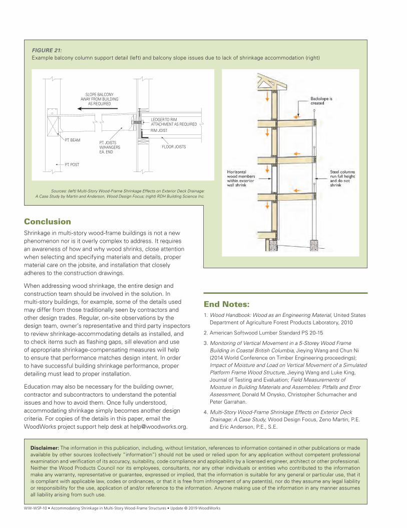
Balcony/Deck SupportAlthough cantilever balconies are common in mid-rise wood-frame construction, some balconies are supported on exterior columns. The potential for shrinkage must be addressed for exterior decks supported by wood-frame walls on the inner edge of the balcony and exterior walls/posts on the outer edge. When utilizing columns to support the outer edge of a balcony attached to a wood-frame building, the slope of the balcony should be taken into account. If the balcony is originally designed to slope slightly away from the building, the balcony could rotate back toward the building as shrinkage occurs in the wood framing but not the exterior balcony columns. This could result in less balcony slope than planned or, worst case, the balcony could end up with a negative slope draining water back toward the building. See Figure 21 for an example of this condition.
Solutions to this include supporting balconies on a row of columns just outboard of the exterior wall (same materials and support conditions as the columns at the balconies’ outer edge), supporting all balcony edges with wood framing and ensuring that the balcony shrinkage zone at each level matches the building’s, utilizing cantilever balconies, or accommodating shrinkage in the initial slope in the balconies such that they would still drain away from the building even if all anticipated building shrinkage occurs. If utilizing the option of a row of columns just outboard of the exterior wall (and potentially not attaching the balcony to the exterior wall), care should be taken to ensure that any differential elevation between the deck surface and adjacent interior floor surface complies with code requirements.
Threaded rod tie-down with shrinkage compensation devices Photos: (left) Simpson Strong-Tie; (right) CLP Systems/Earthbound
For uniform roof uplift, utilizing floor-to-floor connections that have integral shrinkage take-up devices is one way to minimize issues with shrinkage. An example is shown below.
engagement. See the image below for an example of this condition. If issues such as this exist, reengagement of the tension systems is required, either through re-tightening the nuts on threaded rods (and periodically checking that they remain tight) or installation of new tension systems which can accommodate shrinkage as discussed below.
Gap between wood plate and tension-threaded rod without shrinkage compensation Photo: Simpson Strong-Tie
15
$FRA_634_Shrinkage-SolutionPaper.indd 15 5/30/19 10:39 AM
WW-WSP-10 • Accommodating Shrinkage in Multi-Story Wood-Frame Structures • Update © 2019 WoodWorks
ConclusionShrinkage in multi-story wood-frame buildings is not a new phenomenon nor is it overly complex to address. It requires an awareness of how and why wood shrinks, close attention when selecting and specifying materials and details, proper material care on the jobsite, and installation that closely adheres to the construction drawings.
When addressing wood shrinkage, the entire design and construction team should be involved in the solution. In multi-story buildings, for example, some of the details used may differ from those traditionally seen by contractors and other design trades. Regular, on-site observations by the design team, owner’s representative and third party inspectors to review shrinkage-accommodating details as installed, and to check items such as flashing gaps, sill elevation and use of appropriate shrinkage-compensating measures will help to ensure that performance matches design intent. In order to have successful building shrinkage performance, proper detailing must lead to proper installation.
Education may also be necessary for the building owner, contractor and subcontractors to understand the potential issues and how to avoid them. Once fully understood, accommodating shrinkage simply becomes another design criteria. For copies of the details in this paper, email the WoodWorks project support help desk at [email protected].
FIGURE 21:Example balcony column support detail (left) and balcony slope issues due to lack of shrinkage accommodation (right)
Sources: (left) Multi-Story Wood-Frame Shrinkage Effects on Exterior Deck Drainage: A Case Study by Martin and Anderson, Wood Design Focus; (right) RDH Building Science Inc.
Disclaimer: The information in this publication, including, without limitation, references to information contained in other publications or made available by other sources (collectively “information”) should not be used or relied upon for any application without competent professional examination and verification of its accuracy, suitability, code compliance and applicability by a licensed engineer, architect or other professional. Neither the Wood Products Council nor its employees, consultants, nor any other individuals or entities who contributed to the information make any warranty, representative or guarantee, expressed or implied, that the information is suitable for any general or particular use, that it is compliant with applicable law, codes or ordinances, or that it is free from infringement of any patent(s), nor do they assume any legal liability or responsibility for the use, application of and/or reference to the information. Anyone making use of the information in any manner assumes all liability arising from such use.
End Notes:1. Wood Handbook: Wood as an Engineering Material, United States
Department of Agriculture Forest Products Laboratory, 2010
2. American Softwood Lumber Standard PS 20-15
3. Monitoring of Vertical Movement in a 5-Storey Wood Frame Building in Coastal British Columbia, Jieying Wang and Chun Ni (2014 World Conference on Timber Engineering proceedings); Impact of Moisture and Load on Vertical Movement of a Simulated Platform Frame Wood Structure, Jieying Wang and Luke King, Journal of Testing and Evaluation; Field Measurements of Moisture in Building Materials and Assemblies: Pitfalls and Error Assessment, Donald M Onysko, Christopher Schumacher and Peter Garrahan.
4. Multi-Story Wood-Frame Shrinkage Effects on Exterior Deck Drainage: A Case Study, Wood Design Focus, Zeno Martin, P.E. and Eric Anderson, P.E., S.E.
SLOPE BALCONY AWAY FROM BUILDING
AS REQUIRED
P.T. JOISTSW/HANGERSEA. END
FLOOR JOISTS
RIM JOIST
P.T. BEAM
P.T. POST
LEDGER TO RIM ATTACHMENT AS REQUIRED
$FRA_634_Shrinkage-SolutionPaper.indd 16 5/30/19 10:39 AM


![Premier Marine Q-Portal · 2017-03-30 · Concrete Block I Masonry Wood Siding - Wood Frame [l Stone Veneer - Wood Frame C] Foundation: Concrete [X Year Built: 1960 Stucco Wood Frame](https://img.pdfslide.net/doc/110x75/5f9385ea1c2ce46d26753432/premier-marine-q-portal-2017-03-30-concrete-block-i-masonry-wood-siding-wood.jpg)