Embed Size (px)
Citation preview
IOM002GVAE1614
Automation Solutions for oil & gas, defense and aviation applications
Installation and Operations M
anualDispatch and
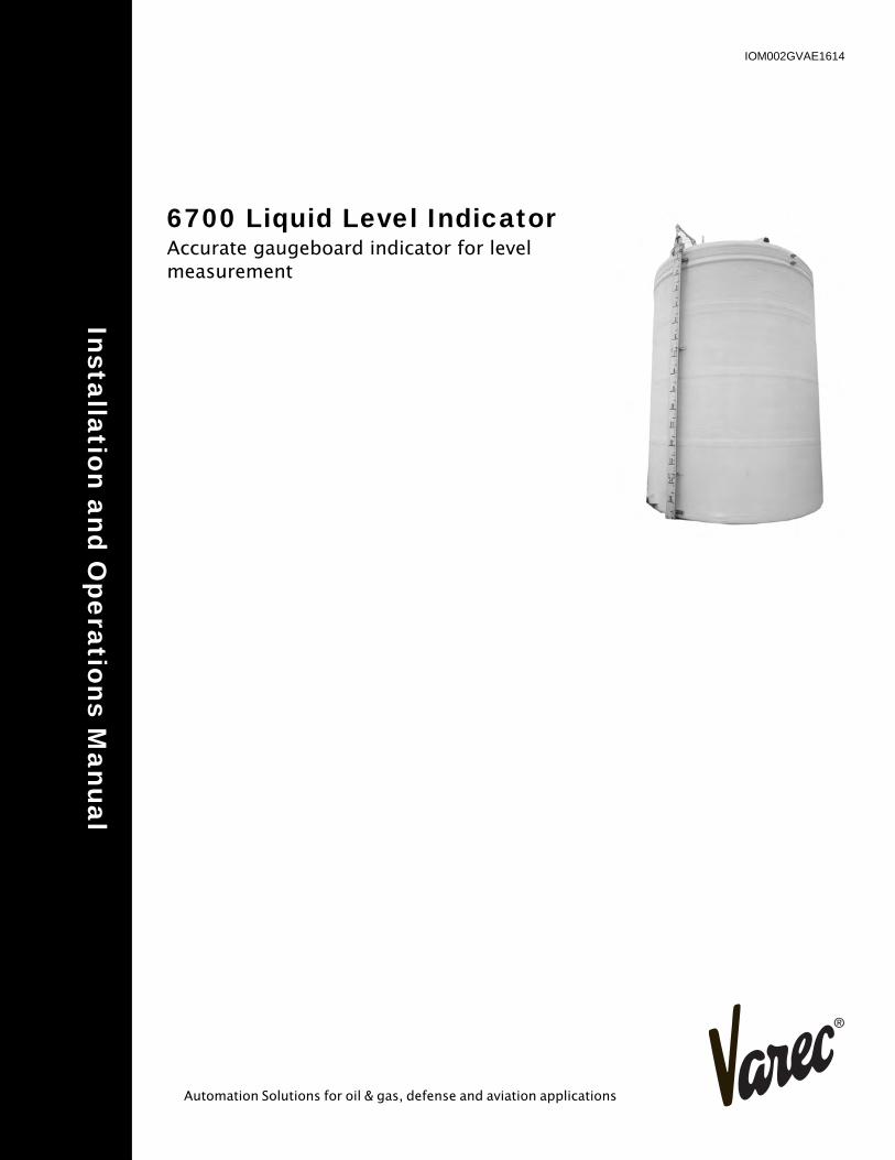
6700 Liquid Level IndicatorAccurate gaugeboard indicator for level measurement

Varec, Inc. iii
Copyright
2013, All rights reserved. Printed in the United States of America.
Except as permitted under the United States Copyright Act of 1976, no part of this publication may be reproduced, stored in a retrieval system or transmitted in any form or by any means - electronic, mechanical, photocopying, recording, or otherwise - without the prior written permission of the Publisher:
Varec, Inc.5834 Peachtree Corners EastPeachtree Corners (Atlanta), Georgia 30092Phone: (770) 447-9202Fax: (770) 662-8939
Trademarks Acknowledged
Varec, Inc. recognizes all other trademarks. Trademarks of other products mentioned in this manual are held by the companies producing them.
FuelsManager®, TankView®, TacFuels®, Varec®, 8130 RTU8130®, and FuelsManager IntoPlane® are registered trademarks of Varec, Inc.
HART® is a registered trademark of HART Communication Foundation, Austin, USA
ToF® is a registered trademark of the company Endress+Hauser GmbH+Co. KG, Maulburg, Germany
FieldCare® is a registered trademark of the company Endress+Hauser Flowtec AG, Rheinach, CH
All other product and service names mentioned are the trademarks of their respective companies.
Disclaimer of Warranties
The contract between the Seller and the Buyer states the entire obligation of the Seller. The contents of this instruction manual shall not become part of or modify any prior or existing agreement, commitment, or relationship between the Seller and Buyer. There are no express or implied warranties set out in this instruction manual. The only warranties that apply are those in the existing contract between the Seller and Buyer.
The 6700 Average Temperature/Water Bottom Sensor and Converter (ATC) has not been tested by Varec under all possible operational conditions, and Varec may not have all the data relative to your application. The information in this instruction manual is not all inclusive and does not and cannot take into account all unique situations. Consequently, the user should review this product literature in view of his or her application. If you have any further questions, please contact Varec for assistance.
Limitations of Seller's Liability
In the event that a court holds that this instruction manual created some new warranties, Seller's liability shall be limited to repair or replacement under the standard warranty clause. In no case shall the Seller's liability exceed that stated as Limitations of Remedy in the contract between the Seller and Buyer.
Use of parts that are not manufactured or supplied by Varec voids any warranty and relieves Varec of any obligation to service the product under warranty. Varec recommends the use of only Varec manufactured or supplied parts to maintain or service Varec 6700 Liquid Level Indicator.
Terms of Use
The information provided in this document is provided "as is" without warranty of any kind. Varec, Inc. disclaim all warranties, either express or implied, including the warranties of merchantability and fitness for a particular purpose. In no event shall Varec, Inc. or its suppliers be liable for any damages whatsoever including direct, indirect, incidental, consequential, loss of business profits or special damages, even if Varec, Inc. or its suppliers have been advised of the possibility of such damages.
This manual is solely intended to describe product installation and functions and should not be used for any other purpose. It is subject to change without prior notice. This manual was prepared with the highest degree of care. However, should you find any errors or have any questions, contact one of our service offices or your local sales agent.
iv Installation and Operations Manual
Safety Precaution Definitions
Caution! Damage to equipment may result if this precaution is disregarded.
Warning! Direct injury to personnel or damage to equipment which can cause injury to personnel may result if this precaution is not followed.
Safety Precautions
Read this manual carefully and make sure you understand its contents before using this product. Follow all instructions and safety guidelines presented in this manual when using this product. If the user does not follow these instructions properly, Varec cannot guarantee the safety of the system.
Note Comply with all applicable regulations, codes, and standards. For safety precautions, the user should refer to the appropriate industry or military standards.
Caution! Electrical Hazard! Read and understand static and lightning electrical protection and grounding described in API 2003. Make certain that the tank installation, operation, and maintenance conforms with the practice set forth therein.
Warning! Make certain that the tank is empty and not in service. Ensure that the tank has been leak and pressure tested as appropriate for the liquid to be stored. Observe appropriate safety precautions in flammable or hazardous liquid storage areas. Do not enter a tank that has contained hydrocarbons, vapors, or toxic materials until a gas free environment is certified. Carry breathing equipment when entering a tank where oxygen may be displaced by carbon dioxide, nitrogen, or other gases. Wear safety glasses as appropriate. Use a hard hat.
Warning! Under most circumstances, the mechanical connections between the guide cables and the anchors provide a resistance to ground that is adequate for the safe electrical drain of electrostatic charges that may accumulate in the tank and the product. Additional grounding may be needed for products with low flash points. Worker activity and worker clothing may accumulate electrostatic charges on the body of a worker. Care should be used in flammable environments to avoid the hazard. Observe American Petroleum Institute (API) Recommended Practice 2003 or other appropriate industry or military standard.
Varec, Inc. v

vi Installation and Operations Manual
Varec, Inc. vii
Contents
1 Introduction . . . . . . . . . . . . . . . . . . . . . . . . . . . . . . . . . . . . . . . . . . . . . . . . 1
Getting Started . . . . . . . . . . . . . . . . . . . . . . . . . . . . . . . . . . . . . . . . . . . . . . . . . . . . . . . . . . . . .1
Accessories . . . . . . . . . . . . . . . . . . . . . . . . . . . . . . . . . . . . . . . . . . . . . . . . . . . . . . . . . . . . . . .2
2 Installation . . . . . . . . . . . . . . . . . . . . . . . . . . . . . . . . . . . . . . . . . . . . . . . . . 7
Oil Seal Installations . . . . . . . . . . . . . . . . . . . . . . . . . . . . . . . . . . . . . . . . . . . . . . . . . . . . . . . . .8
Installation of Oil Seal, 8.5-Inch Water Column Operating Pressure Model . . . . . . . . .9Installation of Oil Seal, 27-Inch Water Column Operating Pressure . . . . . . . . . . . . . . .9
Cone Roof Tank Installation . . . . . . . . . . . . . . . . . . . . . . . . . . . . . . . . . . . . . . . . . . . . . . . . . .10
Initial Calibration . . . . . . . . . . . . . . . . . . . . . . . . . . . . . . . . . . . . . . . . . . . . . . . . . . . . .16Initial Lubrication . . . . . . . . . . . . . . . . . . . . . . . . . . . . . . . . . . . . . . . . . . . . . . . . . . . . .17Reassembly . . . . . . . . . . . . . . . . . . . . . . . . . . . . . . . . . . . . . . . . . . . . . . . . . . . . . . . .17
Cone Roof Tank (Bolted Installation) . . . . . . . . . . . . . . . . . . . . . . . . . . . . . . . . . . . . . . . . . . .17
Initial Calibration . . . . . . . . . . . . . . . . . . . . . . . . . . . . . . . . . . . . . . . . . . . . . . . . . . . . .19Initial Lubrication . . . . . . . . . . . . . . . . . . . . . . . . . . . . . . . . . . . . . . . . . . . . . . . . . . . . .20Reassembly . . . . . . . . . . . . . . . . . . . . . . . . . . . . . . . . . . . . . . . . . . . . . . . . . . . . . . . .20
Cone Roof Tank Installation (Fiberglass Tank) . . . . . . . . . . . . . . . . . . . . . . . . . . . . . . . . . . .22
Initial Calibration . . . . . . . . . . . . . . . . . . . . . . . . . . . . . . . . . . . . . . . . . . . . . . . . . . . . .23Initial Lubrication . . . . . . . . . . . . . . . . . . . . . . . . . . . . . . . . . . . . . . . . . . . . . . . . . . . . .23Reassembly . . . . . . . . . . . . . . . . . . . . . . . . . . . . . . . . . . . . . . . . . . . . . . . . . . . . . . . .23
In-service Tank Installations . . . . . . . . . . . . . . . . . . . . . . . . . . . . . . . . . . . . . . . . . . . . . . . . . .25
General Preparation . . . . . . . . . . . . . . . . . . . . . . . . . . . . . . . . . . . . . . . . . . . . . . . . . .25
Independent Pipe Support Structure . . . . . . . . . . . . . . . . . . . . . . . . . . . . . . . . . . . . . . . . . . .26
Installation of Model 228 Inspection Hatch to Existing Manhole Cover . . . . . . . . . . . . . . . . .26
Anchor Bar Installation . . . . . . . . . . . . . . . . . . . . . . . . . . . . . . . . . . . . . . . . . . . . . . . . . . . . . .26
Float Installation . . . . . . . . . . . . . . . . . . . . . . . . . . . . . . . . . . . . . . . . . . . . . . . . . . . . . . . . . . .29
Initial Lubrication . . . . . . . . . . . . . . . . . . . . . . . . . . . . . . . . . . . . . . . . . . . . . . . . . . . . .30Reassembly . . . . . . . . . . . . . . . . . . . . . . . . . . . . . . . . . . . . . . . . . . . . . . . . . . . . . . . .30
Installation of Model 226 for 20 and 24 Inch Manhole Covers with API Drilling . . . . . . . . . . .30
Typical Auxiliary Equipment Installation . . . . . . . . . . . . . . . . . . . . . . . . . . . . . . . . . . . . . . . . .31
3 Operation . . . . . . . . . . . . . . . . . . . . . . . . . . . . . . . . . . . . . . . . . . . . . . . . . 33
Initial Operation . . . . . . . . . . . . . . . . . . . . . . . . . . . . . . . . . . . . . . . . . . . . . . . . . . . . . . . . . . .33
Normal Operation . . . . . . . . . . . . . . . . . . . . . . . . . . . . . . . . . . . . . . . . . . . . . . . . . . . . . . . . . .33
Calibration and Volume Measurement . . . . . . . . . . . . . . . . . . . . . . . . . . . . . . . . . . . . . . . . . .33
4 Maintenance . . . . . . . . . . . . . . . . . . . . . . . . . . . . . . . . . . . . . . . . . . . . . . . 35
Periodic Maintenance . . . . . . . . . . . . . . . . . . . . . . . . . . . . . . . . . . . . . . . . . . . . . . . . . . . . . . .35
Electrostatic Discharge Hazard . . . . . . . . . . . . . . . . . . . . . . . . . . . . . . . . . . . . . . . . . . . . . . .35
Lubrication . . . . . . . . . . . . . . . . . . . . . . . . . . . . . . . . . . . . . . . . . . . . . . . . . . . . . . . . . . . . . . .35
Oil Recommendations for Oil Seal Accessory Units . . . . . . . . . . . . . . . . . . . . . . . . . .35
Inspection . . . . . . . . . . . . . . . . . . . . . . . . . . . . . . . . . . . . . . . . . . . . . . . . . . . . . . . . . . . . . . . .36
Troubleshooting Common Problems . . . . . . . . . . . . . . . . . . . . . . . . . . . . . . . . . . . . . . . . . . .37
viii Installation and Operations Manual
5 Specifications . . . . . . . . . . . . . . . . . . . . . . . . . . . . . . . . . . . . . . . . . . . . . . 39
Liquid Level Indicator . . . . . . . . . . . . . . . . . . . . . . . . . . . . . . . . . . . . . . . . . . . . . . . . . . . . . . .39
Standard Installation Kits . . . . . . . . . . . . . . . . . . . . . . . . . . . . . . . . . . . . . . . . . . . . . . . . . . . .39
Standard Float Specifications . . . . . . . . . . . . . . . . . . . . . . . . . . . . . . . . . . . . . . . . . . . . . . . . .39
Bottom Anchor Bar Weight . . . . . . . . . . . . . . . . . . . . . . . . . . . . . . . . . . . . . . . . . . . . . . . . . . .40
Other Specifications . . . . . . . . . . . . . . . . . . . . . . . . . . . . . . . . . . . . . . . . . . . . . . . . . . . . . . . .40
Reference Part Numbers . . . . . . . . . . . . . . . . . . . . . . . . . . . . . . . . . . . . . . . . . . . . . . . . . . . .40
Indicator Part Numbers . . . . . . . . . . . . . . . . . . . . . . . . . . . . . . . . . . . . . . . . . . . . . . . .40Float Part Numbers . . . . . . . . . . . . . . . . . . . . . . . . . . . . . . . . . . . . . . . . . . . . . . . . . . .40Sheave Elbow Part Numbers . . . . . . . . . . . . . . . . . . . . . . . . . . . . . . . . . . . . . . . . . . .41Bottom Anchor Bar Weight Part Number . . . . . . . . . . . . . . . . . . . . . . . . . . . . . . . . . .41Oil Seal Accessory Part Numbers . . . . . . . . . . . . . . . . . . . . . . . . . . . . . . . . . . . . . . . .41Order Code Table . . . . . . . . . . . . . . . . . . . . . . . . . . . . . . . . . . . . . . . . . . . . . . . . . . . .43
6 Ordering Information . . . . . . . . . . . . . . . . . . . . . . . . . . . . . . . . . . . . . . . . 43
Varec, Inc. 1
Chapter 1
Introduction
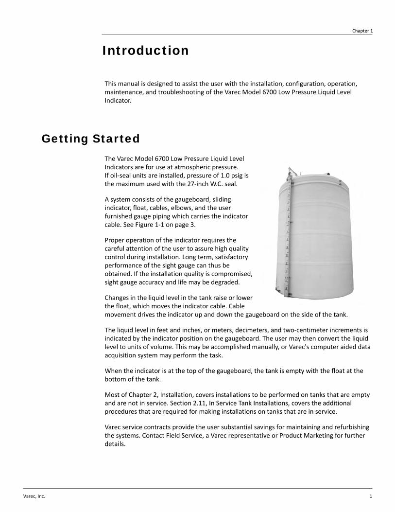
This manual is designed to assist the user with the installation, configuration, operation, maintenance, and troubleshooting of the Varec Model 6700 Low Pressure Liquid Level Indicator.
Getting StartedThe Varec Model 6700 Low Pressure Liquid Level Indicators are for use at atmospheric pressure. If oil‐seal units are installed, pressure of 1.0 psig is the maximum used with the 27‐inch W.C. seal.
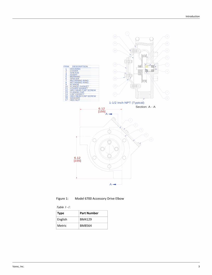
A system consists of the gaugeboard, sliding indicator, float, cables, elbows, and the user furnished gauge piping which carries the indicator cable. See Figure 1‐1 on page 3.
Proper operation of the indicator requires the careful attention of the user to assure high quality control during installation. Long term, satisfactory performance of the sight gauge can thus be obtained. If the installation quality is compromised, sight gauge accuracy and life may be degraded.
Changes in the liquid level in the tank raise or lower the float, which moves the indicator cable. Cable movement drives the indicator up and down the gaugeboard on the side of the tank.
The liquid level in feet and inches, or meters, decimeters, and two‐centimeter increments is indicated by the indicator position on the gaugeboard. The user may then convert the liquid level to units of volume. This may be accomplished manually, or Varec's computer aided data acquisition system may perform the task.
When the indicator is at the top of the gaugeboard, the tank is empty with the float at the bottom of the tank.
Most of Chapter 2, Installation, covers installations to be performed on tanks that are empty and are not in service. Section 2.11, In Service Tank Installations, covers the additional procedures that are required for making installations on tanks that are in service.
Varec service contracts provide the user substantial savings for maintaining and refurbishing the systems. Contact Field Service, a Varec representative or Product Marketing for further details.
Liquid Level Indicator
2 Installation and Operations Manual
AccessoriesVarec manufactures accessories for transmitting and telemetering the information to a Varec Data Acquisition System. Limit switches may be attached to the Liquid Level Indicator system to provide signaling functions. Figures 1‐2 through 1‐5 illustrate some of the accessories available.
Introduction
Varec, Inc. 3
Figure 1: Model 6700 Accessory Drive Elbow
Table 1-1:
Type Part Number
English BM4129
Metric BM8564
6.12[155]
Section: A - A
6.12[155]
A
A
1-1/2 Inch NPT (Typical)
HOUSING1
FLANGE GASKET
HEX HEAD CAP SCREW
HEX HEAD CAP SCREW
COVER GASKET
RETAINING RINGRETAINING RING
12FLANGE CAPCAP GASKET
HEX NUTWASHER
13
15
1716
14
11
FLANGE910
COVER
SHAFTBEARINGSPACER
SHEAVE2
45678
3
DESCRIPTIONITEM
Liquid Level Indicator
4 Installation and Operations Manual
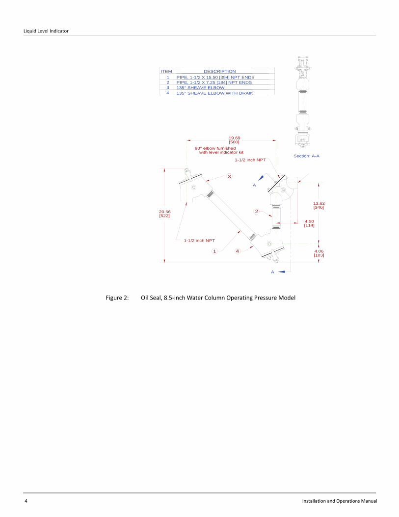
Figure 2: Oil Seal, 8.5‐inch Water Column Operating Pressure Model
PIPE, 1-1/2 X 7.25 [184] NPT ENDSPIPE, 1-1/2 X 15.50 [394] NPT ENDS
135° SHEAVE ELBOW WITH DRAIN135° SHEAVE ELBOW
DESCRIPTION
90° elbow furnishedwith level indicator kit
20.56[522]
1-1/2 inch NPT
1
4
123
ITEM
13.62[346]
4
A
2
4.06[103]
4.50[114]
1-1/2 inch NPT
3
19.69[500]
A
Section: A-A
Introduction
Varec, Inc. 5
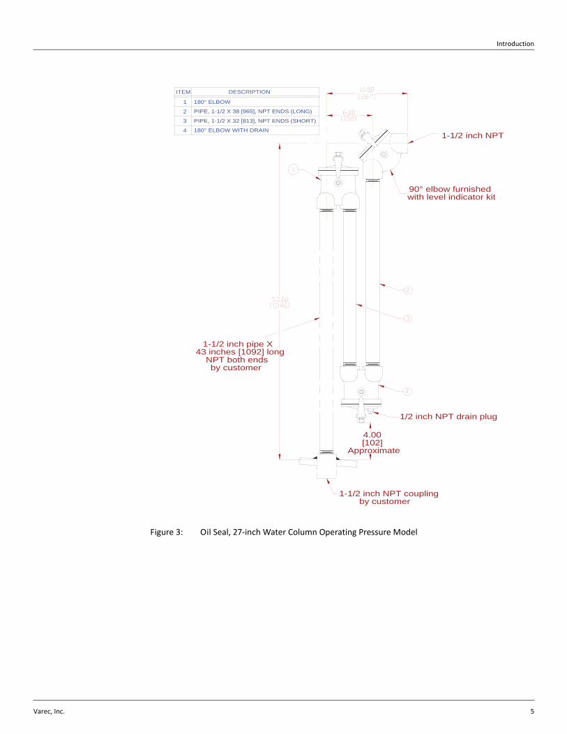
Figure 3: Oil Seal, 27‐inch Water Column Operating Pressure Model
1/2 inch NPT drain plug
180° ELBOW WITH DRAIN4
PIPE, 1-1/2 X 38 [965], NPT ENDS (LONG)
PIPE, 1-1/2 X 32 [813], NPT ENDS (SHORT)
180° ELBOW
2
3
1
ITEM DESCRIPTION
90° elbow furnishedwith level indicator kit
1-1/2 inch NPT
1-1/2 inch pipe X43 inches [1092] long
NPT both endsby customer
1-1/2 inch NPT couplingby customer
4.00[102]
Approximate
Liquid Level Indicator
6 Installation and Operations Manual
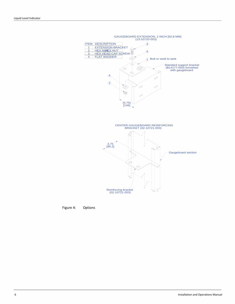
Figure 4: Options
ITEM DESCRIPTION
FLAT WASHERHEX HEAD CAP SCREWHEX NUTEXTENSION BRACKET1
234
HEX NUT
Bolt or weld to tank
Standard support bracket(B14177-003) furnished
with gaugeboard
(5.75)[146]
3
4
1
4
2
Reinforcing bracket(02-10721-003)
GAUGEBOARD EXTENSION, 2 INCH [50.8 MM] (13-10720-003)
CENTER GAUGEBOARD REINFORCING BRACKET (02-10721-003)
3.75[95.2]
Gaugeboard section
Varec, Inc. 7
Chapter 2
Installation
Refer to Chapter 1, Introduction to determine the feature and option codes of the unit to be installed. Use the Table of Contents to determine the appropriate installation figure in this Instruction Manual. These are typical installations. All situations may not be covered. Contact Varec if additional information is needed. It is paramount that the user monitor the quality of the installation to assure long term, accurate performance. If the quality is compromised, inferior operation may result.
Particularly important are:
• Accurate hand gauging referenced to the tank bench mark
• Clean interior of the gauge piping
• No kinks in the tape/cable
• No noticeable binding friction in the mechanism
• Installation cleanliness
• True vertical gauge piping
• Location of float away from inlet pipes of mixers
Warning Make certain that the tank is empty and not in service. Ensure that the tank has been leak and pressure tested as appropriate for the liquid to be stored. Observe appropriate safety precautions in flammable or hazardous liquid storage areas. Do not enter a tank that has contained hydrocarbons, vapours, or toxic materials until a gas free environment is certified. Carry breathing equipment when entering a tank where oxygen may be displaced by carbon dioxide, nitrogen, or other gases. Wear safety glasses as appropriate. Use a hard hat.
Warning Under most circumstances, the mechanical connections between the guide cables and the anchors provide a resistance to ground that is adequate for the safe electrical drain of electrostatic charges that may accumulate in the tank and the product. Additional grounding may be needed for products with low flash points. Worker activity and worker clothing may accumulate electrostatic charges on the body of a worker. Care should be used in flammable environments to avoid the hazard. Observe American Petroleum Institute (API) Recommended Practice 2003 or other appropriate industry or military standard.
The user provides the 1.5‐inch pipe that carries the tape/cable and the necessary mounting and support welding. The user must drill holes in the tank as needed. Assemble the necessary tools and equipment at the work site. Table 2‐1 on page 10 lists typical tools and equipment that may be needed. Use a drop cloth to maintain tool, equipment, and installation kit cleanliness.
Plan the pipe routing. Locate the roof connection into the tank interior within arms reach of a manhole or an inspection hatch.
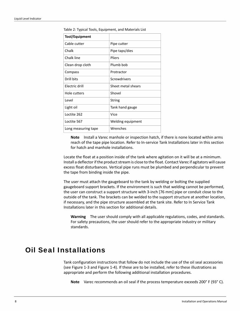
Table 2: Typical Tools, Equipment, and Materials List
Tool/Equipment
Breathing equipment Pick
Liquid Level Indicator
8 Installation and Operations Manual
Note Install a Varec manhole or inspection hatch, if there is none located within arms reach of the tape pipe location. Refer to In‐service Tank Installations later in this section for hatch and manhole installations.
Locate the float at a position inside of the tank where agitation on it will be at a minimum. Install a deflector if the product stream is close to the float. Contact Varec if agitators will cause excess float disturbances. Vertical pipe runs must be plumbed and perpendicular to prevent the tape from binding inside the pipe.
The user must attach the gaugeboard to the tank by welding or bolting the supplied gaugeboard support brackets. If the environment is such that welding cannot be performed, the user can construct a support structure with 3‐inch [76 mm] pipe or conduit close to the outside of the tank. The brackets can be welded to the support structure at another location, if necessary, and the pipe structure assembled at the tank site. Refer to In Service Tank Installations later in this section for additional details.
Warning The user should comply with all applicable regulations, codes, and standards. For safety precautions, the user should refer to the appropriate industry or military standards.
Oil Seal InstallationsTank configuration instructions that follow do not include the use of the oil seal accessories (see Figure 1‐3 and Figure 1‐4). If these are to be installed, refer to these illustrations as appropriate and perform the following additional installation procedures.
Note Varec recommends an oil seal if the process temperature exceeds 200° F (93° C).
Cable cutter Pipe cutter
Chalk Pipe taps/dies
Chalk line Pliers
Clean drop cloth Plumb bob
Compass Protractor
Drill bits Screwdrivers
Electric drill Sheet metal shears
Hole cutters Shovel
Level String
Light oil Tank hand gauge
Loctite 262 Vice
Loctite 567 Welding equipment
Long measuring tape Wrenches
Table 2: Typical Tools, Equipment, and Materials List
Tool/Equipment
Installation
Varec, Inc. 9
Installation of Oil Seal, 8.5-Inch Water Column Operating Pressure Model
Refer to Figure 1‐3 on page 5.
1. Apply appropriate pipe thread compound and install long pipe (1) into 135‐degree elbow with bottom drain (4).
2. Apply pipe thread compound and install short pipe (2) into 135‐degree elbow with bottom drain (4).
3. Apply pipe thread compound and install 135‐degree elbow (3) onto long pipe (1).
4. Apply pipe thread compound and install 90‐degree elbow supplied with gauge kit onto short pipe (2).
5. Adjust the assembly to provide the tape/cable path illustrated in Figure 2‐8 on page 29.
6. Provide 1.5‐inch pipe installation, as required.
7. Proceed with the remainder of the tank installation to the paragraph Initial Lubrication, then fill the oil seal as follows:
a. See Chapter 4, Maintenance, for oil selection.
b. Remove the cover from 90‐degree elbow.
c. Fill to halfway in the short pipe.
Note To drain the oil, open the plug in 135 degree elbow (4).
Installation of Oil Seal, 27-Inch Water Column Operating Pressure
Refer to Figure 1‐4 on page 6.
1. Apply thread pipe compound and install short pipe (3) into 180‐degree elbow (1).
2. Apply pipe thread compound and install 180‐degree elbow (4) onto short pipe (3).
3. Apply pipe thread compound and install long pipe (2) into elbow (4).
4. Apply pipe thread compound and install 90‐degree elbow supplied with gauge kit onto long pipe (2).
5. Complete the assembly to the user furnished 1.5‐inch pipe.
6. Adjust the assembly to provide the tape/cable path as illustrated.
7. Proceed with the remainder of the tank installation to the paragraph Initial Lubrication, then fill the oil seal as follows:
a. See Chapter 4, Maintenance, for oil selection.
b. Remove the cover from 90‐degree elbow.
c. Fill to halfway in the short pipe.
Note To drain the oil, open the plug in 180‐degree elbow (4).
Liquid Level Indicator
10 Installation and Operations Manual
Cone Roof Tank InstallationNote Be sure to read General Preparation at the beginning of this section before pro‐ceeding with this installation.
Refer to Table 1‐1 on page 2. See Figure 2‐1 on page 14 for full travel or Figure 2‐2 on page 15 half travel Liquid Level Indicators.
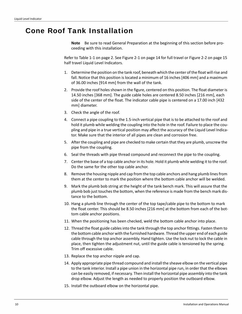
1. Determine the position on the tank roof, beneath which the center of the float will rise and fall. Notice that this position is located a minimum of 16 inches [406 mm] and a maximum of 36.00 inches [914 mm] from the wall of the tank.
2. Provide the roof holes shown in the figure, centered on this position. The float diameter is 14.50 inches [368 mm]. The guide cable holes are centered 8.50 inches [216 mm], each side of the center of the float. The indicator cable pipe is centered on a 17.00 inch [432 mm] diameter.
3. Check the angle of the roof.
4. Connect a pipe coupling to the 1.5‐inch vertical pipe that is to be attached to the roof and hold it plumb while welding the coupling into the hole in the roof. Failure to place the cou‐pling and pipe in a true vertical position may affect the accuracy of the Liquid Level Indica‐tor. Make sure that the interior of all pipes are clean and corrosion free.
5. After the coupling and pipe are checked to make certain that they are plumb, unscrew the pipe from the coupling.
6. Seal the threads with pipe thread compound and reconnect the pipe to the coupling.
7. Center the base of a top cable anchor in its hole. Hold it plumb while welding it to the roof. Do the same for the other top cable anchor.
8. Remove the housing nipple and cap from the top cable anchors and hang plumb lines from them at the center to mark the position where the bottom cable anchor will be welded.
9. Mark the plumb bob string at the height of the tank bench mark. This will assure that the plumb bob just touches the bottom, when the reference is made from the bench mark dis‐tance to the bottom.
10. Hang a plumb line through the center of the top tape/cable pipe to the bottom to mark the float center. This should be 8.50 inches [216 mm] at the bottom from each of the bot‐tom cable anchor positions.
11. When the positioning has been checked, weld the bottom cable anchor into place.
12. Thread the float guide cables into the tank through the top anchor fittings. Fasten them to the bottom cable anchor with the furnished hardware. Thread the upper end of each guide cable through the top anchor assembly. Hand tighten. Use the lock nut to lock the cable in place, then tighten the adjustment nut, until the guide cable is tensioned by the spring. Trim off excessive cable.
13. Replace the top anchor nipple and cap.
14. Apply appropriate pipe thread compound and install the sheave elbow on the vertical pipe to the tank interior. Install a pipe union in the horizontal pipe run, in order that the elbows can be easily removed, if necessary. Then install the horizontal pipe assembly into the tank drop elbow. Adjust the length as needed to properly position the outboard elbow.
15. Install the outboard elbow on the horizontal pipe.
Installation
Varec, Inc. 11
16. Apply pipe thread compound and screw the gaugeboard connector pipe into the outboard elbow.
17. Remove the bolts, cover, and gasket from the outboard elbow and drop a plumb line through the center.
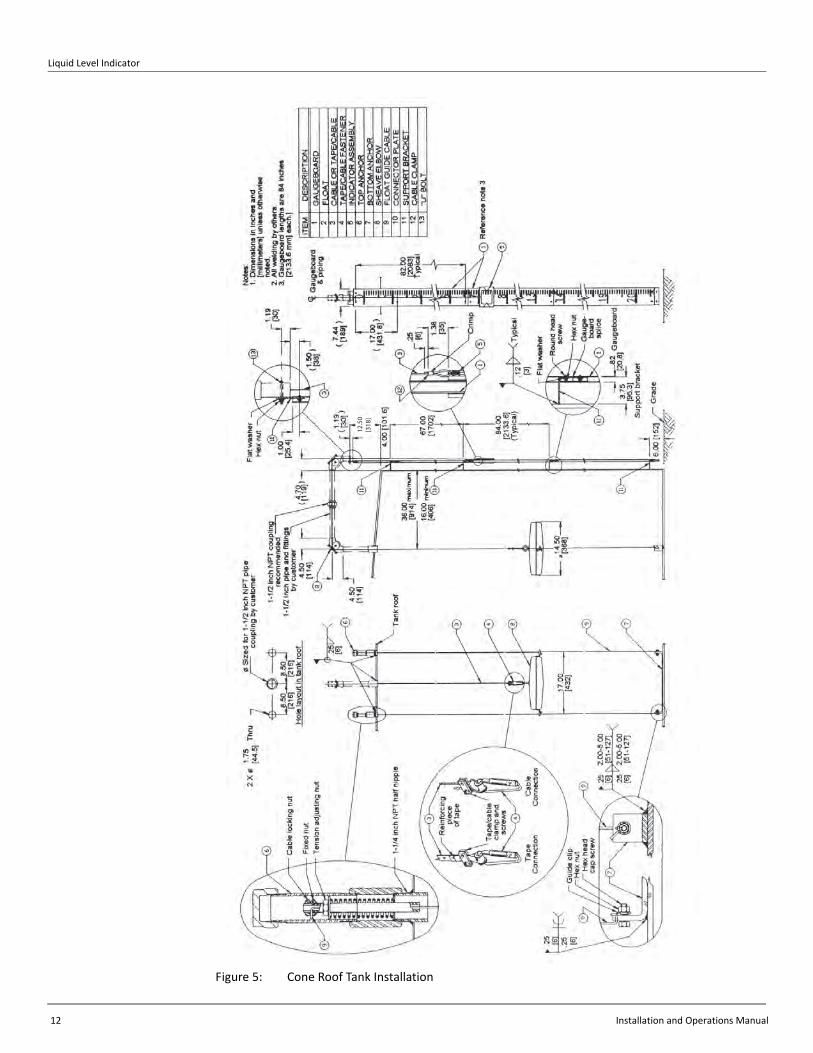
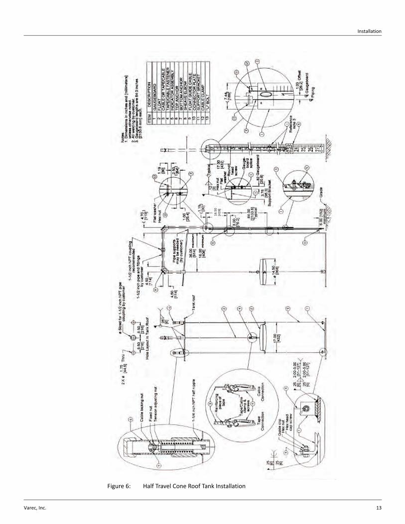
18. Drop a chalk line from the top of the tank parallel with the plumb line and mark the chalk line on the tank wall. See Figure 2‐1 on page 14.
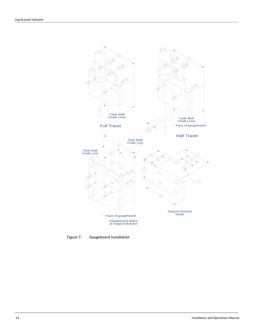
19. Use the width of the gaugeboard (7.44 inches [189 mm]) at the bottom of the tank wall and chalk register marks for the width as follows:
Full Travel Gaugeboard:Board centered with chalked plumb line (see Figure 2‐1 on page 14).
Half Travel Gaugeboard:Board offset (1.03 inches [26.2 mm]) to the right of the chalked plumb line (see Figure 2‐2 on page 15).
20. Do the same at the top of the tank.
21. Make chalk line marks between the top and bottom register mark to aid in keeping the gaugeboard sections centered and parallel during installation.
22. Weld the gaugeboard support brackets into position. See Figure 2‐1 and notice the relative position of the top bracket. All other welds are seven feet below the previous weld, except for the last one at the bottom of the tank, which is six inches [152 mm] above the grade line.
23. Use the “U” bolt and nuts (see Figure 2‐1) to attach the gaugeboard connector to the pipe. The pipe should extend one inch [25.4 mm] below the “U” bolt.
24. Attach the top section of the gaugeboard to the connector plate. Make certain that it is centered on the chalk line.
25. Attach the remainder of the sections to the bottom of the tank. Make certain that each section is centered on the chalk line (see Figure 2‐1).
Note To fit the gaugeboard to the tank, cut the highest‐numbered gaugeboard section at the marker that is 4.50 inches greater than the tank height to adjust the fit to the total height to the tank.
Liquid Level Indicator
12 Installation and Operations Manual
Figure 5: Cone Roof Tank Installation
12.50
[318
]
Installation
Varec, Inc. 13
Figure 6: Half Travel Cone Roof Tank Installation
16.5
0[4
19]
Liquid Level Indicator
14 Installation and Operations Manual
Figure 7: Gaugeboard Installation
Face of gaugeboard
Gaugeboard Spliceat Support Bracket
Tank WallChalk Line
Tank WallChalk Line
Support BracketDetail
Half Travel
Tank WallChalk Lines
Full Travel Face of gaugeboard
Tank WallChalk Lines
Installation
Varec, Inc. 15
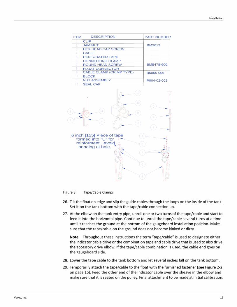
Figure 8: Tape/Cable Clamps
26. Tilt the float on edge and slip the guide cables through the loops on the inside of the tank. Set it on the tank bottom with the tape/cable connection up.
27. At the elbow on the tank entry pipe, unroll one or two turns of the tape/cable and start to feed it into the horizontal pipe. Continue to unroll the tape/cable several turns at a time until it reaches the ground at the bottom of the gaugeboard installation position. Make sure that the tape/cable on the ground does not become kinked or dirty.
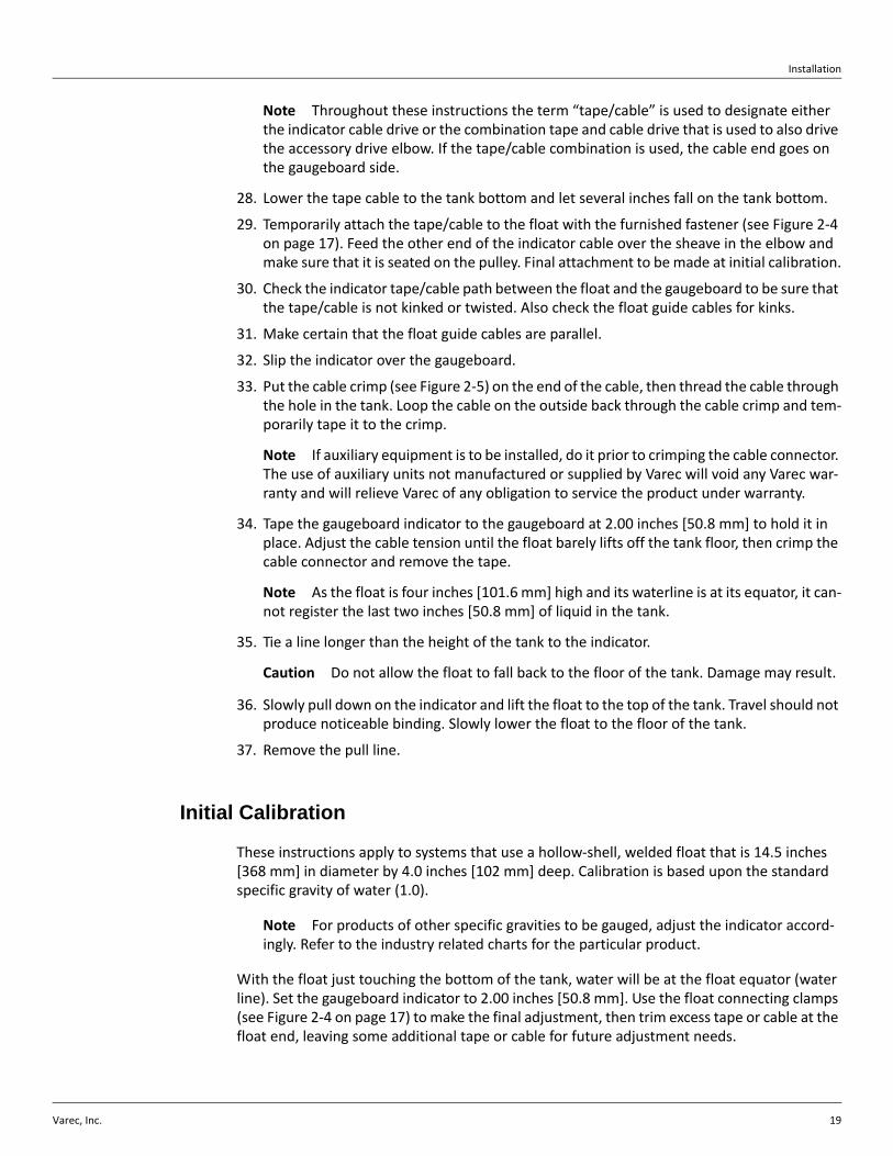
Note Throughout these instructions the term “tape/cable” is used to designate either the indicator cable drive or the combination tape and cable drive that is used to also drive the accessory drive elbow. If the tape/cable combination is used, the cable end goes on the gaugeboard side.
28. Lower the tape cable to the tank bottom and let several inches fall on the tank bottom.
29. Temporarily attach the tape/cable to the float with the furnished fastener (see Figure 2‐2 on page 15). Feed the other end of the indicator cable over the sheave in the elbow and make sure that it is seated on the pulley. Final attachment to be made at initial calibration.
6 inch [155] Piece of tapeformed into "U" forreinforment. Avoidbending at hole.
HEX HEAD CAP SCREW
CABLE CLAMP (CRIMP TYPE)FLOAT CONNECTOR
NUT ASSEMBLYSEAL CAP
BLOCK
ROUND HEAD SCREW
PERFORATED TAPE
JAM NUT
CONNECTING CLAMP
CABLE
CLIPITEM DESCRIPTION
P004-02-002
B6065-006
BM5478-600
PART NUMBER
BM3612
Liquid Level Indicator
16 Installation and Operations Manual
30. Check the indicator tape/cable path between the float and the gaugeboard to be sure that the tape/cable is not kinked or twisted. Also check the float guide cables for kinks.
31. Make certain that the float guide cables are parallel.
Note If auxiliary equipment is to be installed, do it prior to crimping the cable connector. The accessory drive elbow should not be used for half‐travel level indication. The use of auxiliary units not manufactured or supplied by Varec will void any Varec warranty and will relieve Varec of any obligation to service the product under warranty.
32. Install indicator.
Full Travel Gaugeboard:Slip the indicator over the gaugeboard. Put the cable crimp on the end of the cable, then thread the cable through the hole in the indicator. Loop the cable on the outside back through the cable crimp and temporarily tape it to the crimp (see Figure 2‐1 on page 14).
Half Travel Gaugeboard:Remove one side channel from the indicator. Position indicator on the gaugehead and reassemble the side channel. Thread the cable through the pulley on the indicator. Put the cable crimp on the end of the cable. Thread the cable through the hole in the gaugeboard connector plate. Loop the cable on back through the cable crimp and temporarily tape it to the crimp (see Figure 2‐2 on page 15).
33. Tape the gaugeboard indicator to the gaugeboard at 2.00 inches [50.8 mm] to hold it in place. Adjust the cable tension until the float barely lifts off the tank floor, then crimp the cable connector and remove the tape.
Note As the float is four inches [101.6 mm] high and its waterline is at its equator, it can‐not register the last two inches [50.8 mm] of liquid in the tank.
34. Tie a line longer than the height of the tank to the indicator.
Caution Do not allow the float to fall back to the floor of the tank. Damage may result.
35. Slowly pull down on the indicator and lift the float to the top of the tank. Travel should not produce noticeable binding. Slowly lower the float to the floor of the tank.
36. Remove the pull line.
Initial Calibration
These instructions apply to systems that use a hollow‐shell, welded float that is 14.5 inches [368 mm] in diameter by 4.0 inches [102 mm] deep. Calibration is based upon the standard specific gravity of water (1.0).
Note For products of other specific gravities to be gauged, adjust the indicator accord‐ingly. Refer to the industry related charts for the particular product.
With the float just touching the bottom of the tank, water will be at the float equator (water line). Use the float connecting clamps (see Figure 2‐2) to make the final adjustment, then trim excess tape or cable at the float end, leaving some additional tape or cable for future adjustment needs.
Installation
Varec, Inc. 17
Initial Lubrication
Apply a light oil to the elbow and indicator sheaves.
Reassembly
1. Reinstall the covers, gaskets, and bolts on the elbows.
2. Close the tank manholes and inspection covers.
Cone Roof Tank (Bolted Installation)Note Be sure to read General Preparation at the beginning of this section before pro‐ceeding with this installation.
Refer to Table 1‐1 on page 2. See Figure 2‐5 on page 22.
1. Determine the position on the tank roof, beneath which the center of the float will rise and fall. Notice that this position is located a minimum of 16 inches [406 mm] and a maximum of 36.00 inches [914 mm] from the wall of the tank.
2. Provide the roof holes shown in the figure, centered on this position. The float diameter is 14.50 inches [368 mm]. The guide cable holes are centered 8.50 inches [216 mm], each side of the center of the float. The tape pipe is centered on a 17.00 inch [432 mm] diame‐ter.
3. Check the angle of the roof. The roof pitch for the furnished gaugeboard is 1 inch [25.4 mm] in 12 inches [305 mm].
4. Connect a pipe deck flange to the 1.5‐inch vertical pipe that is to be attached to the roof.
5. Bolt the flange to the roof. Check that it is plumb.
Note Failure to place the flange coupling and pipe in a true vertical position may affect the accuracy of the indicator. Make sure that the interior of all pipes are clean and free of corrosion.
6. After the deck flange and pipe are checked to make certain that they are plumb, unscrew the pipe from the coupling. Apply pipe thread compound and reconnect the pipe to the coupling.
7. Center the base of a top cable anchor in its hole. Hold it plum and bolt it to the roof. Do the same for the other top cable anchor.
8. Remove the housing nipple and cap from the top cable anchors and hang plumb lines from them at the center to mark the position where the bottom cable anchor will be attached. A hanging weight anchor may be ordered from Varec if it is not practical to bolt or weld the bottom guide cable anchor to the floor of the tank. For tanks that are in service, the hanging anchor must be used.
9. Mark the plumb bob string at the height of the tank bench mark. This will assure that the plumb bob just touches the bottom when the reference is made from the bench mark dis‐tance to the bottom.
Liquid Level Indicator
18 Installation and Operations Manual
10. Hang a plumb line through the center of the top tape/cable pipe to the bottom to mark the float center. This should be 8.50 inches [216 mm] at the bottom from each of the bot‐tom cable anchor positions. When the positioning has been checked, attach the bottom cable anchor into place.
11. Thread the float cables into the tank through the top anchor fittings. Fasten them to the bottom cable anchors with the furnished hardware.
12. Thread the upper end of each guide cable through the top anchor assembly. Hand tighten. Use the lock nut to lock the cable in place, then tighten the adjustment nut, until the guide cable is tensioned by the spring.
13. Replace the housing nipple and cap.
14. Apply appropriate pipe thread compound and install the sheave elbow on the vertical pipe to the tank interior. Install a pipe union in the horizontal pipe run, in order that the elbows can be easily removed, if necessary. Then install the horizontal pipe assembly into the tank drop elbow. Adjust the length as needed to properly position the outboard elbow.
15. Install the outboard elbow on the horizontal pipe.
16. Apply pipe thread compound and screw the gaugeboard connector pipe into the outboard elbow.
17. Remove the bolts, cover, and gasket from the outboard elbow and drop a plumb line through the center.
18. Drop a chalk line from the top of the tank parallel with the plumb line and mark the chalk line on the tank wall. See Figure 2‐3 on page 16.
19. Use the width of the gaugeboard at the bottom of the tank wall and chalk register marks for the width centered on the chalk line.
20. Do the same at the top of the tank.
21. Make chalk line marks between the top and bottom register mark to aid in keeping the gaugeboard sections centered and parallel during installation.
22. Bolt the gaugeboard support brackets into position (see Figure 2‐5). The first gaugehead support bracket mounts near the top of the tank. The others are spaced at seven foot [2.13.m] intervals except for the one at the bottom of the tank.
23. Use the “U” bolt and nuts (see Figure 2‐3) to attach the gaugeboard connector to the pipe. The pipe should extend one inch [25.4 mm] below the “U” bolt.
24. Attach the top section of the gaugeboard to the connector plate. Make certain that it is centered on the chalk line.
25. Attach the remainder of the sections to the bottom of the tank. Make certain that each section is centered on the chalk line (see Figure 2‐3).
Note To fit the gaugeboard to the tank, cut the lowest gaugeboard section at the marker that is 4.50 inches greater than the tank height to adjust the fit to the total height to the tank
26. Tilt the float on edge and slip the guide cables through the loops on the inside of the tank. Set it on the tank bottom with the tape/cable connection up.
27. At the elbow on the tank entry pipe, unroll one or two turns of the tape/cable and start to feed it into the horizontal pipe. Continue to unroll the tape/cable several turns at a time until it reaches the ground at the bottom of the gaugeboard installation position. Make sure that the tape/cable on the ground does not become kinked or dirty.
Installation
Varec, Inc. 19
Note Throughout these instructions the term “tape/cable” is used to designate either the indicator cable drive or the combination tape and cable drive that is used to also drive the accessory drive elbow. If the tape/cable combination is used, the cable end goes on the gaugeboard side.
28. Lower the tape cable to the tank bottom and let several inches fall on the tank bottom.
29. Temporarily attach the tape/cable to the float with the furnished fastener (see Figure 2‐4 on page 17). Feed the other end of the indicator cable over the sheave in the elbow and make sure that it is seated on the pulley. Final attachment to be made at initial calibration.
30. Check the indicator tape/cable path between the float and the gaugeboard to be sure that the tape/cable is not kinked or twisted. Also check the float guide cables for kinks.
31. Make certain that the float guide cables are parallel.
32. Slip the indicator over the gaugeboard.
33. Put the cable crimp (see Figure 2‐5) on the end of the cable, then thread the cable through the hole in the tank. Loop the cable on the outside back through the cable crimp and tem‐porarily tape it to the crimp.
Note If auxiliary equipment is to be installed, do it prior to crimping the cable connector. The use of auxiliary units not manufactured or supplied by Varec will void any Varec war‐ranty and will relieve Varec of any obligation to service the product under warranty.
34. Tape the gaugeboard indicator to the gaugeboard at 2.00 inches [50.8 mm] to hold it in place. Adjust the cable tension until the float barely lifts off the tank floor, then crimp the cable connector and remove the tape.
Note As the float is four inches [101.6 mm] high and its waterline is at its equator, it can‐not register the last two inches [50.8 mm] of liquid in the tank.
35. Tie a line longer than the height of the tank to the indicator.
Caution Do not allow the float to fall back to the floor of the tank. Damage may result.
36. Slowly pull down on the indicator and lift the float to the top of the tank. Travel should not produce noticeable binding. Slowly lower the float to the floor of the tank.
37. Remove the pull line.
Initial Calibration
These instructions apply to systems that use a hollow‐shell, welded float that is 14.5 inches [368 mm] in diameter by 4.0 inches [102 mm] deep. Calibration is based upon the standard specific gravity of water (1.0).
Note For products of other specific gravities to be gauged, adjust the indicator accord‐ingly. Refer to the industry related charts for the particular product.
With the float just touching the bottom of the tank, water will be at the float equator (water line). Set the gaugeboard indicator to 2.00 inches [50.8 mm]. Use the float connecting clamps (see Figure 2‐4 on page 17) to make the final adjustment, then trim excess tape or cable at the float end, leaving some additional tape or cable for future adjustment needs.
Liquid Level Indicator
20 Installation and Operations Manual
Initial Lubrication
Apply a light oil to the elbow and indicator sheaves.
Reassembly
1. Reinstall the covers, gaskets, and bolts on the elbows.
2. Close the tank manholes and inspection covers.
Installation
Varec, Inc. 21
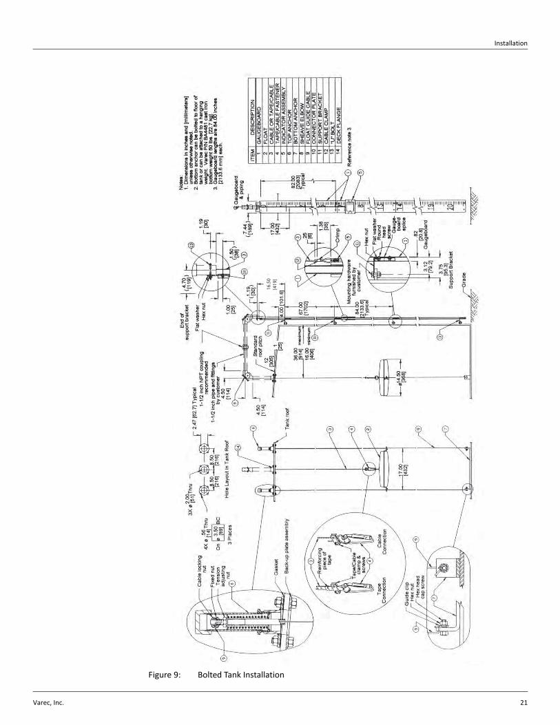
Figure 9: Bolted Tank Installation
16.50
[419
]
Liquid Level Indicator
22 Installation and Operations Manual
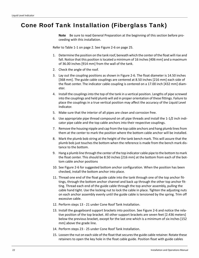
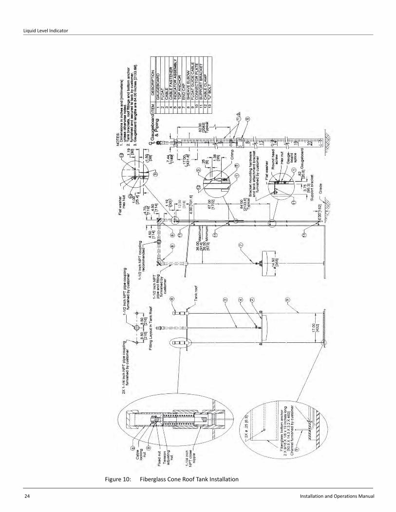
Cone Roof Tank Installation (Fiberglass Tank)Note Be sure to read General Preparation at the beginning of this section before pro‐ceeding with this installation.
Refer to Table 1‐1 on page 2. See Figure 2‐6 on page 25.
1. Determine the position on the tank roof, beneath which the center of the float will rise and fall. Notice that this position is located a minimum of 16 inches [406 mm] and a maximum of 36.00 inches [914 mm] from the wall of the tank.
2. Check the angle of the roof.
3. Lay out the coupling positions as shown in Figure 2‐6. The float diameter is 14.50 inches [368 mm]. The guide cable couplings are centered at 8.50 inches [216 mm] each side of the float center. The indicator cable coupling is centered on a 17.00 inch [432 mm] diam‐eter.
4. Install the couplings into the top of the tank in a vertical position. Lengths of pipe screwed into the couplings and held plumb will aid in proper orientation of these fittings. Failure to place the couplings in a true vertical position may affect the accuracy of the Liquid Level Indicator.
5. Make sure that the interior of all pipes are clean and corrosion free.
6. Use appropriate pipe thread compound on all pipe threads and install the 1‐1/2 inch indi‐cator pipe cable and the top cable anchors into their respective couplings.
7. Remove the housing nipple and cap from the top cable anchors and hang plumb lines from them at the center to mark the position where the bottom cable anchor will be installed.
8. Mark the plumb bob string at the height of the tank bench mark. This will assure that the plumb bob just touches the bottom when the reference is made from the bench mark dis‐tance to the bottom.
9. Hang a plumb line through the center of the top indicator cable pipe to the bottom to mark the float center. This should be 8.50 inches [216 mm] at the bottom from each of the bot‐tom cable anchor positions
10. See Figure 2‐6 for suggested bottom anchor configuration. When the position has been checked, install the bottom anchor into place.
11. Thread one end of the float guide cable into the tank through one of the top anchor fit‐tings, through the bottom anchor channel and back up through the other top anchor fit‐ting. Thread each end of the guide cable through the top anchor assembly, pulling the cable hand tight. Use the locking nut to lock the cable in place. Tighten the adjusting nuts on each anchor assembly evenly until the guide cable is tensioned by the spring. Trim off excessive cable.
12. Perform steps 13 ‐ 21 under Cone Roof Tank Installation.
13. Install the gaugeboard support brackets into position. See Figure 2‐6 and notice the rela‐tive position of the top bracket. All other support brackets are seven feet [2.436 meters] below the previous bracket, except for the last one which is a minimum of six inches [152 mm] above the grade line.
14. Perform steps 23 ‐ 25 under Cone Roof Tank Installation.
15. Loosen the nut on each side of the float that secures the guide cable retainer. Rotate these retainers to open the key hole in the float cable guide. Position float with guide cables
Installation
Varec, Inc. 23
routed through the float guide holes and rotate the guide cable retainers to lock the guide cable in place. Tighten the nuts and set the float on the tank bottom or bottom anchor.
16. Perform steps 27 ‐ 32 under Cone Roof Tank Installation.
17. Tape the gaugeboard indicator to the gaugeboard at a level indication of 2.00 inches [50.8 mm] plus the height of the bottom anchor. Adjust the cable tension until the float barely lifts from its resting place. Crimp the cable connector and remove the tape.
Note As the float is four inches [101.6 mm] high and its waterline is at its equator, it can‐not register the last two inches [50.8 mm] plus any bottom anchor height of liquid in the tank.
18. Complete the installation by performing steps 34 ‐ 36 under Cone Roof Tank Installation.
Initial Calibration
These instructions apply to systems that use a hollow‐shell, fiberglass float that is 14.5 inches [368 mm] in diameter by 4.0 inches [102 mm] deep. Calibration is based upon the standard specific gravity of water (1.0).
Note For products of other specific gravities to be gauged, adjust the indicator accord‐ingly. Refer to the industry related charts for the particular product.
With the float just touching the bottom of the tank, water will be at the float equator (water line). Use the float connecting clamps (see Figure 2‐4 on page 17) to make the final adjustment, then trim excess tape or cable at the float end, leaving some additional tape or cable for future adjustment needs. Install the heat shrinkable seal cap over the cut end of the cable.
Initial Lubrication
Apply a light oil to the elbow and indicator sheaves.
Reassembly
1. Reinstall the covers, gaskets, and bolts on the elbows.
2. Close the tank manholes and inspection covers.
Liquid Level Indicator
24 Installation and Operations Manual
Figure 10: Fiberglass Cone Roof Tank Installation
12.50
[318
]
Installation
Varec, Inc. 25
In-service Tank InstallationsThis section covers the additional procedures that are required for making installations on tanks that are in service. Varec service contracts provide the user substantial savings for maintaining and refurbishing the systems. Contact Varec Product Marketing for further information.
General Preparation
Use the Table of Contents to determine the appropriate installation figure in this Instruction Manual. These are typical installations. All situations may not be covered. Contact Varec if additional information is needed.
Warning Make certain that the tank is empty and not in service. Ensure that the tank has been leak and pressure tested as appropriate for the liquid to be stored. Observe appropriate safety precautions in flammable or hazardous liquid storage areas. Do not enter a tank that has contained hydrocarbons, vapours, or toxic materials until a gas free environment is certified. Carry breathing equipment when entering a tank where oxygen may be displaced by carbon dioxide, nitrogen, or other gases. Wear safety glasses as appropriate. Use a hard hat.
Warning Under most circumstances, the mechanical connections between the guide cables and the anchors provide a resistance to ground that is adequate for the safe electrical drain of electrostatic charges that may accumulate in the tank and the product. Additional grounding may be needed for products with low flash points. Worker activity and worker clothing may accumulate electrostatic charges on the body of a worker. Care should be used in flammable environments to avoid the hazard. Observe American Petroleum Institute (API) Recommended Practice 2003 or other appropriate industry or military standard.
The user provides the 1.5‐inch pipe that carries the tape/cable and the necessary mounting and support welding. The user must drill holes as needed.
Assemble the necessary tools and equipment at the work site. Refer to Table 2‐1 on page 10 for suggested tools and equipment. Plan the pipe routing. Position the roof connection installation into the tank interior within arms reach of a manhole or an inspection hatch.
Use these procedures to install a Varec manhole or inspection hatch, if there is none located within arms reach of the tape pipe location.
Locate the float at a position inside of the tank where surface agitation on it will be at a minimum. Install a deflector, if the product stream is close to the float. Contact Varec if agitators will cause excess float disturbances. Vertical pipe runs must be plumbed and perpendicular to prevent the tape/cable from binding inside the pipe.
The user must attach the gaugeboard to the tank by welding or bolting the supplied gaugeboard brackets. If the environment is such that welding cannot be performed, the user can construct a support structure close to the outside of the tank.
Liquid Level Indicator
26 Installation and Operations Manual
Warning The user should comply with all applicable regulations, codes, and standards. For safety precautions, the user should refer to the appropriate industry or military standards.
Independent Pipe Support StructureWhere the environment is such that welding cannot be performed, construct an appropriate support structure of 3‐inch [76 mm] pipe in segments away from the tank and weld the brackets there. Use good commercial practices. Make certain that vertical segments will be plumb and the horizontal segments level. Use a concrete footing to support the tankside vertical segment (see Figure 2‐7 on page 28).
Installation of Model 228 Inspection Hatch to Existing Manhole Cover
See Figure 2‐7 on page 28 to modify an existing manhole cover with a model 228 (Part Number BM6746) type inspection hatch.
1. Remove the cover to a safe welding location.
2. Cut a rectangular hole 6.00 inches [152 mm] x 15.75 inches [400 mm] in the cover.
3. Cut a 2.50‐inch [63.5 mm] diameter hole in the cover to carry the tape drop pipe.
4. Cut two 1.75‐inch [44.5 mm] diameter holes in the cover to carry the top guide cable anchors.
5. Disassemble the inspection cover and gasket from the frame.
6. Weld the inspection cover frame to the manhole cover.
7. Weld the guide cable anchor nipples and the tape/cable drop pipe coupling in place. make certain that they are vertical and correctly centered.
8. Carry the modified cover assembly back to the tank site. Orient the modified manhole cover as shown and reinstall.
9. Refer to the appropriate tank configuration figure and install the tape/cable piping and gaugeboard.
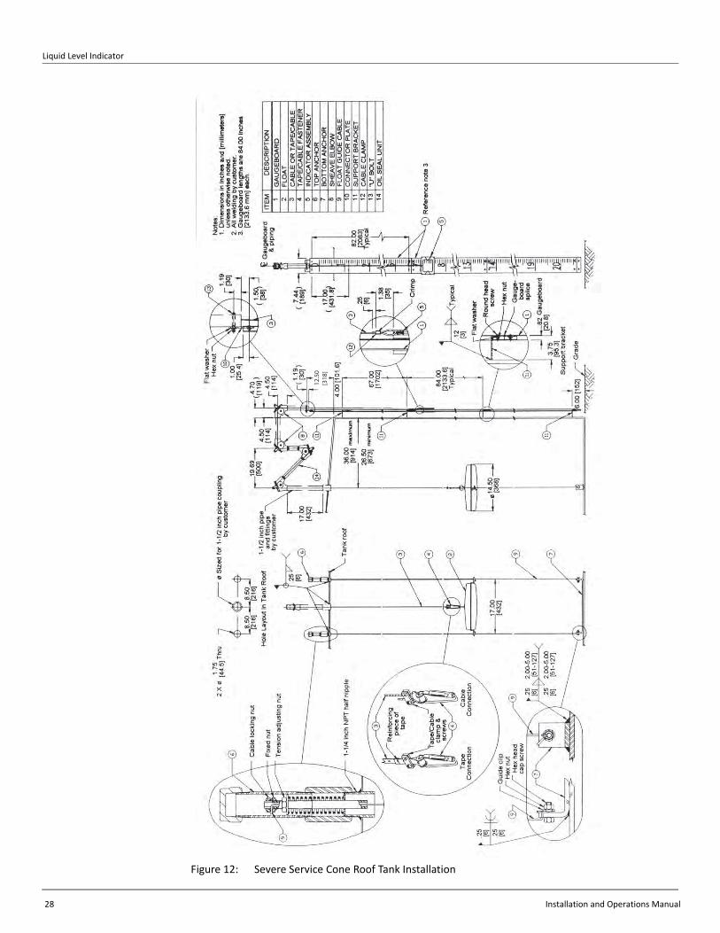
Anchor Bar InstallationVarec supplies an anchor bar for in‐service installations (Part Number BA4481) that must be ordered separately. It is for normal service only. The guide cables fasten to the anchor bar with cable clamps (see Figure 2‐7 on page 28). For severe or extreme service installations, contact Varec. A severe service installation is shown in Figure 2‐8 on page 29.

Installation
Varec, Inc. 27
Figure 11: Typical In‐Service Tank Installation
Figure 228 Inspection Cover(for existing 20 inch andlarger manhole covers)
See Details B & C
Existing standard roof manholewith gasket and mounting hardware
16.00 [406] minimum36.00 [914] maximum
Cable clamps
Pipe support bracketsfor welding to customer
support structure
17.00[432]
15.00[381]
3 Places
Guided float
Piping and fittingsfurnished by customer
8.50 [216] 8.50 [216]
Detail: C
15.75 [400]Cover cutout
Cover cutout6.00 [152]
Detail: BExisting Manhole Cover Modifications
10.00 [254]
19.75 [502]
3.31[84]
.18[4.8]
Guide cableanchor nipple
[6].25
(6.00 [152])
ITEM
54321
HEX HEAD CAP SCREWHEX NUT
GASKETCOVER
DESCRIPTIONFRAME ASSEMBLY
Customer constructedsupport structure set
in concrete
[3].12
84.00[2133.6](Typical)
[1702]67.00
Anchor bar
Hex headcap screw
Float guidecable
Detail: A
Typical
14 Places
2X ø Thru
(Assembled)
ø Sized for 1-1/2 inchNPT pipe coupling
by customer
"In Service" anchor barordered separately
2.75 [70]
.25 [6]
Float guidecables
[44.5]
1.75
14 Places
Liquid Level Indicator
28 Installation and Operations Manual
Figure 12: Severe Service Cone Roof Tank Installation
12.50
[318
]
Installation
Varec, Inc. 29
Float Installation1. Refer to appropriate tank configuration and install top anchors less long nipple and cap.
2. Thread the float guide cables into the tank through the top anchor fittings and pull the ends back through the inspection hatch.
3. Fasten the bottom anchor to the guide cables (see Figure 2‐7 on page 28) and lower the anchor slowly through the inspection hatch into the tank.
4. When anchor bar is resting on tank bottom, remove cable slack by hand. Tighten cable locking nut to secure cable in place.
5. Tighten the adjustment nut until the guide cable is tensioned by the spring. Trim excess cable.
6. Use pipe thread compound and install top anchor nipples and cap.
Note Throughout these instructions the term “tape/cable” is used to designate either the indicator cable drive or the combination tape and cable drive that is used to also drive the accessory drive elbow. If the tape/cable combination is used, the cable end goes on the gaugeboard side.
Caution If the tape/cable binds in the pipe during threading, check the pipe for corrosion and other obstructions. Check the tape/cable to make certain that it did not kink. Friction in the pipe will affect accuracy and may break the tape/cable.
7. Thread the tape/cable through the horizontal pipe and into the gaugeboard connector pipe.
8. Put a clean drop cloth on the ground and push the tape through a few turns at a time from the drop pipe elbow, until the tape/cable is unrolled. Make sure that the tape/cable falling to the ground does not become kinked or dirty.
9. Use the tank bench mark as a guide and pull back enough tape/cable to drop from the bench mark to the tank bottom. Mark that position on the tape for reference.
10. Thread the tape through the drop pipe into the tank and pull the end back through the inspection hatch.
11. Install the tape/cable to the float connector with the clamps and screws provided (see Fig‐ure 2‐4 on page 17).
12. Attach the tape/cable connector to the float, pass it through the hatch and attach the eyes to the guide cables.
Caution Do not allow the float to fall to the surface of the product. Damage may result.
13. Lower the float until it is hanging from the tape/cable. Inspect the tape/cable and cables for twists and kinks. Make sure that the cables are parallel, then lower the float to the sur‐face of the product.
14. Make a hand gauge measurement of the tank product level. Use the bench mark reference to calibrate the hand gauge. Use extra care to make certain that this measurement is accu‐rate because the accuracy of the sight gauge indicator depends upon it.
15. If an accessory is to be installed, perform the installation. Refer to the main text auxiliary equipment installation paragraphs and then continue the installation. The hole size, bolt pattern, and coupling of Varec accessories mates with the sheave drive elbow. Each mating auxiliary unit has a slotted coupling that engages the drive pin on the sprocket sheave.

Liquid Level Indicator
30 Installation and Operations Manual
Mate the accessory with the sprocket sheave drive. Use the hex head cap screws and washers to attach the accessory unit to the drive elbow.
Refer to the manual for the accessory unit, if installed, and check out the operation of the accessory as appropriate.
Note The use of auxiliary units not manufactured or supplied by Varec will void any Varec warranty and will relieve Varec of any obligation to service the product under war‐ranty.
16. Install the gaugeboard and indicator. Refer to the appropriate tank configuration.
17. Set indicator at measured product level.
18. Adjust the tape/cable tension until the float barely lifts from its natural floating position, then crimp the cable connector.
19. Tie a line to the indicator.
20. Slowly pull down on the indicator and lift the float to the top of the tank. Travel should not produce noticeable binding. Slowly lower the float to the product level. Check that any installed accessory performed properly during this test.
Caution Do not allow the float to fall to the surface of the product. Damage may result.
21. Refer to appropriate tank configuration to set the indicator at the full tank position, then use the hand gauge measurement to recheck the current product level.
Initial Lubrication
Apply a light oil to the elbow and indicator sheaves.
Reassembly
1. Reinstall the covers, gaskets, and bolts on the elbows.
2. Close the tank manholes and inspection covers.
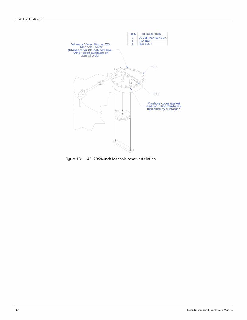
Installation of Model 226 for 20 and 24 Inch Manhole Covers with API Drilling
See Figure 2‐9 on page 33 to install Model 226 20 inch (Part Number BM3443) and 24 inch (Part Number BM3607) manhole covers with API drilling.
1. Remove the existing manhole cover.
2. Separate the Model 226 cover by removing the flange connecting bolts.
3. Install the cover half with the pipe coupling to the top of the tank.
4. Refer to the appropriate tank configuration figure to check the tank configuration and install the tape/cable piping and gaugeboard.
Installation
Varec, Inc. 31
Complete the Anchor Bar Installation, Float Installation, Initial Lubrication, and Reassembly sections of the previous procedure, Installation of Model 228 Inspection Hatch to Existing Manhole Cover. See also the following section, Typical Auxiliary Equipment Installation.
Typical Auxiliary Equipment InstallationTo install auxiliary equipment, an auxiliary elbow drive adapter kit (P/N 13‐08821) is required. The kit contains the English drive elbow (P/N BM4129) and the tape/cable combination (P/N B7678‐106). This has a sprocket sheave that is driven by the English tape/cable combination. Usually this is installed on the outboard connection pipe elbow.
Note The use of auxiliary units not manufactured or supplied by Varec will void any Varec warranty and will relieve Varec of any obligation to service the product under war‐ranty.
The perforated tape portion of the tape/cable combination must be seated on the sprocket sheave throughout the travel of the indicator. The cable portion cannot drive an auxiliary device. The cable portion attached to the pulley of the half‐travel indicator may reach the gaugeboard connector sheave before a vertical tank is empty if the gaugeboard is mounted high on the tank.
1. Remove the bolts, cover, and gasket from the elbow.
2. Remove the drive adapter flange bolts, washers, flange cap, and gasket.
3. Install the elbow on the indicator connector pipe.
4. Refer to the appropriate tank configuration installation procedures above and thread the tape/cable through the elbow. The cable segment attaches to the gaugeboard indicator. The tape segment attaches to the float. Position the tape/cable splice below the auxiliary drive elbow with the float at the bottom of the tank.
5. Seat the perforated tape portion of the tape/cable combination on the sheave sprocket and thread it through the indicator connector pipe.
6. Attach the auxiliary unit to the adapter flange.
7. Attach the auxiliary unit with adapter flange to the drive elbow ensuring that the sprocket drive pin engages the slotted coupling of the auxiliary unit.
8. Refer to the auxiliary unit manual for operation and checkout procedures.
9. Refer to the appropriate tank configuration to complete the installation.
Liquid Level Indicator
32 Installation and Operations Manual
Figure 13: API 20/24‐Inch Manhole cover Installation
Whesoe Varec Figure 226Manhole Cover
(Standard for 20 inch API-650.Other sizes available on
special order.)
Manhole cover gasketand mounting hardwarefurnished by customer.
COVER PLATE ASSY.ITEM
1
32
DESCRIPTION
HEX NUTHEX BOLT
Varec, Inc. 33
Chapter 3
Operation
Initial OperationCaution Initial filling of the tank must be a reduced rate of flow, until the float travel and sight indicator operation are verified. This checks that the installation was correctly made and prevents possible damage to the gauge system. On floating roof tanks this is particu‐larly important because the tape/cable travel has not been checked during the installation.
1. Station an observer at the gaugeboard.
2. Begin filling the tank to raise the float several feet (about three feet or one meter) from the bottom.
3. Continue filling the tank to the desired level.
4. Hand gauge the product and compare the measurement with the gaugeboard indication. If they do not coincide, adjust the cable at the indicator or connector plate. Use the spare cable crimp, if necessary.
Normal OperationWhen the tank is full, the indicator will be at the bottom of the gaugeboard. As the liquid is removed from the tank, the float will fall and the indicator will rise.
Calibration and Volume MeasurementTank gauging measurements provide appropriate inventory checks and a valuable method of checking marine receipts and metered custody transfers. Accuracy of measurements requires that a number of factors be considered:
• Density and specific gravity of product as determined from representative samples
• Sediment in the tank
• Water content in the product
• Gross volume
• Temperature of the product
• Tank‐bottom deformation
It is the user's responsibility to appropriately consider these and other factors in his application. For example, oil tank capacity tables are calculated for product at 60 oF. A higher temperature will cause the tank to expand and the actual volume will be greater than the volume at the standard temperature.

Liquid Level Indicator
34 Installation and Operations Manual
Accuracy of hand gauging is extremely important, as it is used to set the Varec Liquid Level Indicator. Careful reference to the benchmark of the tank will help assure accuracy of the levels as they are read from the indicator during operation.
Table 3: API Standards
API Standard Description
2550 Method For Measurement And Calibration Of Upright Cylindrical Tanks (ANSI/ASTM D1220)
2545 Method of Gauging Petroleum and Petroleum Products (ANSI/ASTM D1085)
2540 Chapter 11.1 (ANSI/ASTM D1250) for Volume Correction Factors. Refer also to API 2545.
Manual of Petroleum Measurement Standards, Chapter 3 ‐ Tank Gauging, Section 1B, Standard Practice for Level Measurement of Liquid Hydrocarbons in Stationary Tanks by Automatic Tank Gauging.

Varec, Inc. 35
Chapter 4
Maintenance
Periodic MaintenanceVarec Model 6700 Low Pressure Liquid Level Indicators are designed for long service life. Like any other measuring device, Liquid Level Indicators require regular, periodic service to maintain the original performance. Table 4‐1 on page 38 provides some suggested periodic service. Minimum maintenance will lengthen the service life and assure more accurate reading of the indicator.
Varec provides maintenance service contracts that provide regular periodic inspection and maintenance at substantial savings. Some repair tasks may require special tools.
Warning Observe appropriate safety precautions in flammable or hazardous liquid storage areas. Do not enter a tank that has contained hydrocarbons, vapors, or toxic materials, until a gas‐free environment is certified. Carry breathing equipment when entering a tank where oxygen may be depleted with carbon dioxide, nitrogen or other gases.
Electrostatic Discharge HazardUnder most circumstances, the mechanical connections between the guide cables and anchors provide a resistance to ground that is adequate for the safe electrical drain of electrostatic charges that may accumulate in the tank and the product. Additional grounding may be needed for products with low flash points. Worker activity and worker clothing may accumulate electrostatic charges on the body of a worker. Care should be used in flammable environments to avoid the hazard. Observe American Petroleum Institute (API) Recommended Practice 2003 or other appropriate industry or military standard.
LubricationLubricate moving parts of the elbow and indicator sheaves at regular intervals. Use a light‐weight oil.
Oil Recommendations for Oil Seal Accessory Units
GENERAL SERVICE
• Low pour point, food grade, water white, mineral oil.
Liquid Level Indicator
36 Installation and Operations Manual
Brand Names:
• ARCO Prime Grade 70
• Lyondell DuoPrime 70 (Product Code 16402)
SERVICE BELOW 25 0F (‐4 0C)
• Automotive antifreeze and water (50/50 mix)
• (Propylene Glycol‐based antifreeze such as “Sierra” should be considered for environmentally sensitive areas.)
Caution These oils may not be compatible with edible oils and edible liquids. Use prod‐uct compatible substitutes for tanks holding products for human or animal consumption or products that may react chemically with the oil.
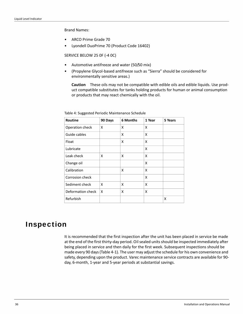
InspectionIt is recommended that the first inspection after the unit has been placed in service be made at the end of the first thirty‐day period. Oil sealed units should be inspected immediately after being placed in service and then daily for the first week. Subsequent inspections should be made every 90 days (Table 4‐1). The user may adjust the schedule for his own convenience and safety, depending upon the product. Varec maintenance service contracts are available for 90‐day, 6‐month, 1‐year and 5‐year periods at substantial savings.
Table 4: Suggested Periodic Maintenance Schedule
Routine 90 Days 6 Months 1 Year 5 Years
Operation check X X X
Guide cables X X
Float X X
Lubricate X
Leak check X X X
Change oil X
Calibration X X
Corrosion check X
Sediment check X X X
Deformation check X X X
Refurbish X
Maintenance
Varec, Inc. 37
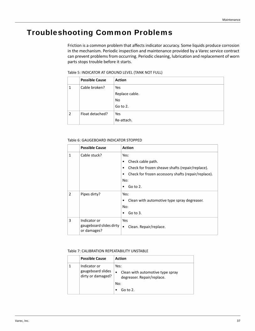
Troubleshooting Common ProblemsFriction is a common problem that affects indicator accuracy. Some liquids produce corrosion in the mechanism. Periodic inspection and maintenance provided by a Varec service contract can prevent problems from occurring. Periodic cleaning, lubrication and replacement of worn parts stops trouble before it starts.
Table 5: INDICATOR AT GROUND LEVEL (TANK NOT FULL)
Possible Cause Action
1 Cable broken? Yes
Replace cable.
No
Go to 2.
2 Float detached? Yes
Re‐attach.
Table 6: GAUGEBOARD INDICATOR STOPPED
Possible Cause Action
1 Cable stuck? Yes:
• Check cable path.
• Check for frozen sheave shafts (repair/replace).
• Check for frozen accessory shafts (repair/replace).
No:
• Go to 2.
2 Pipes dirty? Yes:
• Clean with automotive type spray degreaser.
No:
• Go to 3.
3 Indicator or gaugeboard slides dirty or damages?
Yes
• Clean. Repair/replace.
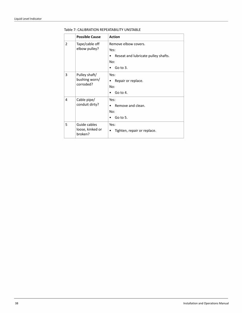
Table 7: CALIBRATION REPEATABILITY UNSTABLE
Possible Cause Action
1 Indicator or gaugeboard slides dirty or damaged?
Yes:
• Clean with automotive type spray degreaser. Repair/replace.
No:
• Go to 2.
Liquid Level Indicator
38 Installation and Operations Manual
2 Tape/cable off elbow pulley?
Remove elbow covers.
Yes:
• Reseat and lubricate pulley shafts.
No:
• Go to 3.
3 Pulley shaft/bushing worn/corroded?
Yes:
• Repair or replace.
No:
• Go to 4.
4 Cable pipe/conduit dirty?
Yes:
• Remove and clean.
No:
• Go to 5.
5 Guide cables loose, kinked or broken?
Yes:
• Tighten, repair or replace.
Table 7: CALIBRATION REPEATABILITY UNSTABLE
Possible Cause Action
Varec, Inc. 39
Chapter 5
Specifications
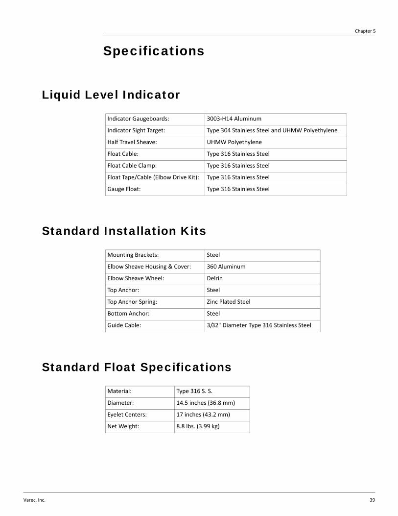
Liquid Level Indicator
Standard Installation Kits
Standard Float Specifications
Indicator Gaugeboards: 3003‐H14 Aluminum
Indicator Sight Target: Type 304 Stainless Steel and UHMW Polyethylene
Half Travel Sheave: UHMW Polyethylene
Float Cable: Type 316 Stainless Steel
Float Cable Clamp: Type 316 Stainless Steel
Float Tape/Cable (Elbow Drive Kit): Type 316 Stainless Steel
Gauge Float: Type 316 Stainless Steel
Mounting Brackets: Steel
Elbow Sheave Housing & Cover: 360 Aluminum
Elbow Sheave Wheel: Delrin
Top Anchor: Steel
Top Anchor Spring: Zinc Plated Steel
Bottom Anchor: Steel
Guide Cable: 3/32" Diameter Type 316 Stainless Steel
Material: Type 316 S. S.
Diameter: 14.5 inches (36.8 mm)
Eyelet Centers: 17 inches (43.2 mm)
Net Weight: 8.8 lbs. (3.99 kg)
Liquid Level Indicator
40 Installation and Operations Manual
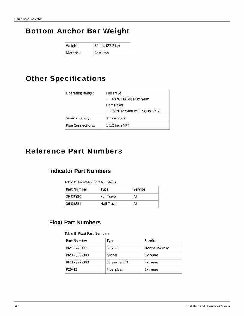
Bottom Anchor Bar Weighta
Other Specifications
Reference Part Numbers
Indicator Part Numbers
Float Part Numbers
Weight: 52 lbs. (22.2 kg)
Material: Cast Iron
Operating Range: Full Travel
• 48 ft. [14 M] Maximum
Half Travel
• 97 ft. Maximum (English Only)
Service Rating: Atmospheric
Pipe Connections: 1 1/2 inch NPT
Table 8: Indicator Part Numbers
Part Number Type Service
06‐09830 Full Travel All
06‐09831 Half Travel All
Table 9: Float Part Numbers
Part Number Type Service
BM9074‐000 316 S.S. Normal/Severe
BM12338‐000 Monel Extreme
BM12339‐000 Carpenter 20 Extreme
P29‐43 Fiberglass Extreme
Specifications
Varec, Inc. 41
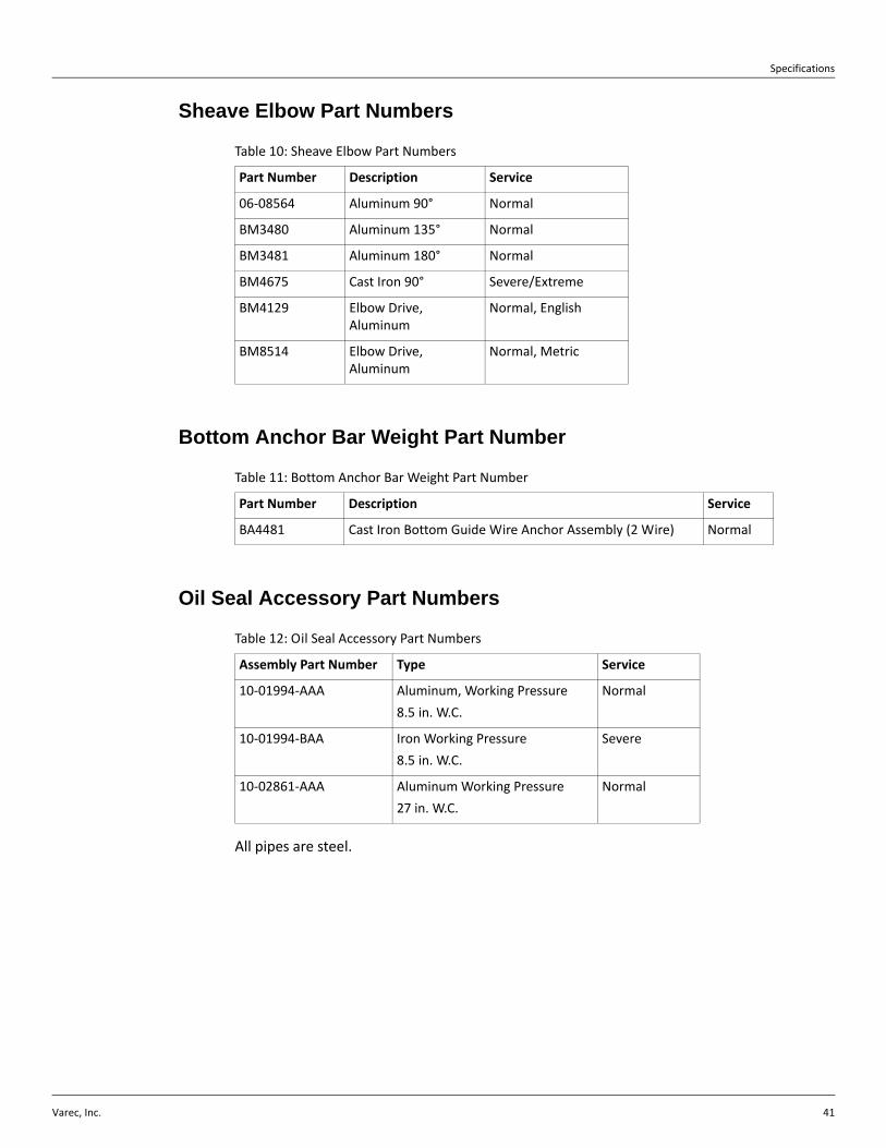
Sheave Elbow Part Numbers
Bottom Anchor Bar Weight Part Number
Oil Seal Accessory Part Numbers
All pipes are steel.
Table 10: Sheave Elbow Part Numbers
Part Number Description Service
06‐08564 Aluminum 90° Normal
BM3480 Aluminum 135° Normal
BM3481 Aluminum 180° Normal
BM4675 Cast Iron 90° Severe/Extreme
BM4129 Elbow Drive, Aluminum
Normal, English
BM8514 Elbow Drive, Aluminum
Normal, Metric
Table 11: Bottom Anchor Bar Weight Part Number
Part Number Description Service
BA4481 Cast Iron Bottom Guide Wire Anchor Assembly (2 Wire) Normal
Table 12: Oil Seal Accessory Part Numbers
Assembly Part Number Type Service
10‐01994‐AAA Aluminum, Working Pressure
8.5 in. W.C.
Normal
10‐01994‐BAA Iron Working Pressure
8.5 in. W.C.
Severe
10‐02861‐AAA Aluminum Working Pressure
27 in. W.C.
Normal
Liquid Level Indicator
42 Installation and Operations Manual
Varec, Inc. 43
Chapter 6
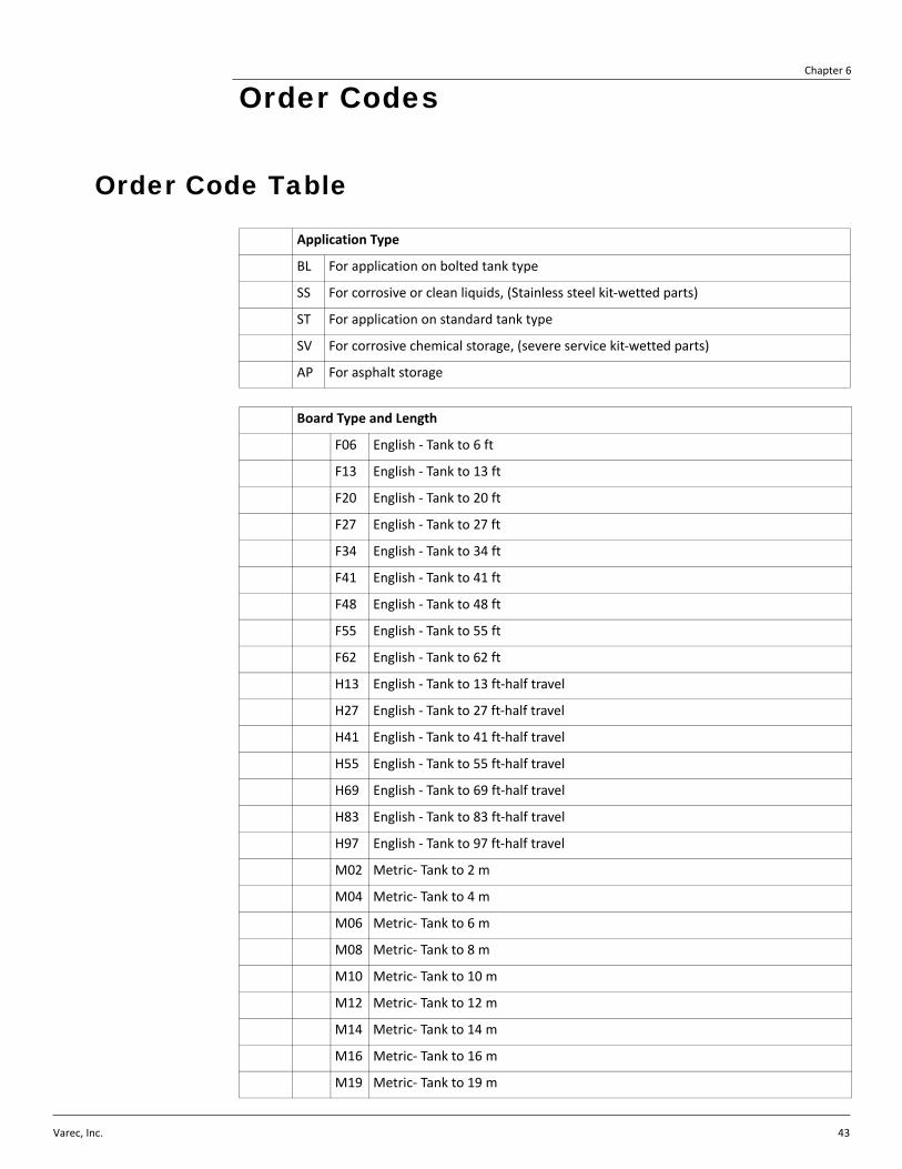
Order Codes
Order Code Table
Application Type
BL For application on bolted tank type
SS For corrosive or clean liquids, (Stainless steel kit‐wetted parts)
ST For application on standard tank type
SV For corrosive chemical storage, (severe service kit‐wetted parts)
AP For asphalt storage
Board Type and Length
F06 English ‐ Tank to 6 ft
F13 English ‐ Tank to 13 ft
F20 English ‐ Tank to 20 ft
F27 English ‐ Tank to 27 ft
F34 English ‐ Tank to 34 ft
F41 English ‐ Tank to 41 ft
F48 English ‐ Tank to 48 ft
F55 English ‐ Tank to 55 ft
F62 English ‐ Tank to 62 ft
H13 English ‐ Tank to 13 ft‐half travel
H27 English ‐ Tank to 27 ft‐half travel
H41 English ‐ Tank to 41 ft‐half travel
H55 English ‐ Tank to 55 ft‐half travel
H69 English ‐ Tank to 69 ft‐half travel
H83 English ‐ Tank to 83 ft‐half travel
H97 English ‐ Tank to 97 ft‐half travel
M02 Metric‐ Tank to 2 m
M04 Metric‐ Tank to 4 m
M06 Metric‐ Tank to 6 m
M08 Metric‐ Tank to 8 m
M10 Metric‐ Tank to 10 m
M12 Metric‐ Tank to 12 m
M14 Metric‐ Tank to 14 m
M16 Metric‐ Tank to 16 m
M19 Metric‐ Tank to 19 m
Liquid Level Indicator
44 Installation and Operations Manual
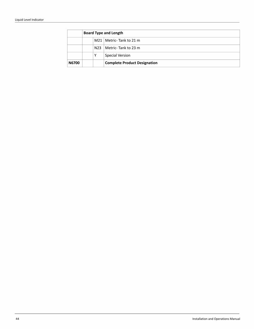
M21 Metric‐ Tank to 21 m
N23 Metric‐ Tank to 23 m
Y Special Version
N6700 Complete Product Designation
Board Type and Length


Varec, Inc. • 5834 Peachtree Corners East, Peachtree Corners (Atlanta), GA 30092 USATel: +1 (770) 447-9202 • Fax: +1 (770) 662-8939
www.varec.com
© 2013 Varec, Inc. All Rights Reserved. This document is for information purposes only. Varec, Inc. makes no warranties, express or implied, in this summary. The names of actual companies and products mentioned herein may be the trademarks of their respective owners.
Document CodeIOM002GVAE1614