Embed Size (px)
Citation preview
Universidad Autónoma de Madrid
Escuela politécnica superior
Proyecto fin de carrera
ACCURATE TRAJECTORY
REPRESENTATION FOR VIDEO
SURVEILLANCE
Ingeniería de Telecomunicación
Gonzalo Varela Bartrina
Enero 2013

ACCURATE TRAJECTORY
REPRESENTATION FOR VIDEO
SURVEILLANCE
AUTOR: Gonzalo Varela Bartrina
TUTOR: Ebroul Izquierdo
PONENTE: José María Martínez Sánchez
Multimedia and Vision Research Group
School of Electronic Engineering and Computer Science
Queen Mary, University of London
Enero 2013
i


Resumen
Resumen
El objetivo de este proyecto es el estudio, desarrollo y evaluación de un sistema robusto de rep-resentación de trayectorias de objetos para vídeo vigilancia. El sistema debe permitir trabajarde forma �exible con las trayectorias, generando una representación útil para aplicaciones demás alto nivel.La solución propuesta comprende cuatro fases, cada una con un propósito determinado. Laprimera fase consiste en un algoritmo que se encarga de realizar las tareas necesarias para ex-traer las trayectorias de los objetos en movimiento de los vídeos. La segunda fase o comprendeuna serie de técnicas destinadas a mejorar y depurar la información obtenida en la fase ante-rior. En la tercera etapa, las trayectorias se dividen para facilitar su posterior uso y análisis.Por último, se desarrolla una representación precisa de las trayectorias que también permite lareconstrucción de las trayectorias originales.Para la evaluación del sistema se utilizan dos bases de datos distintas, tratando de incluir losescenarios y situaciones más frecuentes en vídeo vigilancia. Cada técnica utilizada en el sistemase evalúa de manera individual, determinando su e�cacia para la consecución del objetivo �nal.Para la correcta evaluación de algunas partes del proyecto ha sido necesario construir una basede datos en la que los objetos de interés han sido anotados manualmente para su comparacióncon los objetos detectados por el sistema.
Palabras Clave
Video vigilancia, trayectorias de objetos en movimiento, representación de trayectorias, divisiónen subtrayectorias, �ltro de Saviztky-Golay, reconstrucción.
iii
Accurate trajectory representation for video surveillance
Abstract
The main objective of this thesis is to �nd, develop and evaluate a robust system to representtrajectories extracted from moving objects in surveillance videos. The proposed system shouldallow a �exible and accurate work with trajectories, generating a useful trajectory representationfor high level applications.The system is divided in four principal steps, each one with its own purpose. The �rst step isin charge of extract the trajectories of moving objects from the target videos. The second stepapplies a number of techniques to enhance the data obtained in the previous step. In the thirdstage, trajectories are split to facilitate further work with trajectories. Finally, in the fourthstep, the subpaths previously obtained are characterized by a number of features that allowfurther trajectory reconstruction.To evaluate the performance of the proposed system, all the experiments are run over twodi�erent datasets. These datasets include the most common scenarios in video surveillance. Eachimplemented step is analysed individually, determining its e�ectiveness towards reaching thethesis objectives. A ground truth dataset has been created to evaluate some of the implementedtechniques. This ground truth is made of hand annotated objects from several videos of theevaluation datasets.
Key words
Video surveillance, moving objects trajectories, trajectory representation, trajectory division insubpaths, Saviztky-Golay �lter, trajectory reconstruction.
iv

Acknowledgements
First of all, I want to thank Ebroul for the opportunity to develop my master thesis abroad andthe people of the MMV for their warm welcome. I also want to thank Chema for his support allalong the thesis, Paula Fonseca for her aid during my stay in London and Álvaro for his helpwith the datasets.
A special mention deserves Virginia, without whose help this thesis would never have been�nished.
Secondly, I would like to thank all the teachers and professors I've had since school, becausethey have provided me the tools and knowledge that have brought me here.
Special thanks to my family, which has always supported me, in anything I have decided toundertake. Thanks to my father for inculcate in me curiosity and hunger for knowledge. Thanksto my mother for her example of constant �ght and coherence. Thank the both of you, for teachme the value of critical thinking. Finally, say thanks to my grandmother, who has always beenan example of courage against all odds.
I want to say, how much I appreciate all my friends. I would like to dedicate a couple oflines to each you, but given that's not possible, I will try my best because you deserve it.To all the people from the Engineering School of the UAM, for the laughs shared in class or inthe labs, but especially for those shared in the café and in the grass. Your friendship and helpduring these years has been absolutely invaluable.To all the friends I've made in London, both the spanish and the people from QMR&M Society,thanks for this unforgettable year.Thanks to the people of the Liceo, for all these years of friendship. Even if we don't see asfrequently as I would like, I will always have time for all of you.To Eva, Miko, Chavo, Aly, Sara and to all my lifelong friends, thank you for all your a�ectionand friendship. Life is much better with you at my side.
Gonzalo Varela Bartrina
January, 2012
v
Accurate trajectory representation for video surveillance
Agradecimientos
En primer me gustaría agradecer a Ebroul la posibilidad de desarrollar mi proyecto fuera, lo queme ha proporcionado una experiencia tremendamente enriquecedora. A la gente del MMV porsu cálida acogida. Agradecer a Chema sus gestiones desde el principio y su apoyo a lo largo delproyecto, a Paula Fonseca toda su ayuda durante mi estancia en Londres y a Álvaro su ayudacon las bases de datos.
Mención especial merece Virginia, porque sin su ayuda este proyecto jamás habría salido ala luz.
En segundo lugar, quería dar las gracias a los profesores que he tenido a lo largo de miformación universitaria y escolar. Me habéis proporcionado las herramientas y el conocimientonecesarios. Quiero destacar que esa formación no sólo ha sido cientí�ca, sino también humanís-tica y personal. Sin vosotros nunca hubiera llegado hasta aquí.
Quiero mencionar de una forma especial a mi familia, que siempre me ha apoyado en lo quehe decidido emprender. A mi padre, por inculcarme la curiosidad, el amor al conocimiento. A mimadre, por su ejemplo de lucha y coherencia. A ambos, por enseñarme el valor del pensamientocrítico. A mi abuela, por ser un pilar de coraje contra viento y marea. Este proyecto es, enparte, vuestro.
A todos mis amigos, ojala pudiera dedicar personalmente unas líneas a cada uno pero, dadoel contexto, os habréis de conformar con estas migas.A la gente de la Escuela, por tantas risas compartidas a la luz de las pantallas de los laboratorios,pero sin duda por aquellas compartidas en la cafetería o el césped. Vuestra compañía y ayudaha resultado invaluable en estos años de carrera. Gracias a todos.A todos los amigos que hice en Londres, tanto los españoles, como la gente de la QMR&MSociety, gracias por hacer de este año una estancia inolvidable.A la gente del Liceo por tantos años de amistad y porque sean muchos más. Porque aunque nonos veamos tan a menudo como me gustaría, siempre tendré un hueco para vosotros.A Eva, Miko, Chavo, Aly, Sara, y a mis amigos de toda la vida por todo vuestro cariño y amistaddesde siempre. La vida compartida con vosotros vale mucho más.
Gonzalo Varela Bartrina
Enero, 2012
vi
Contents
Figure index x
Table index xii
1 Introduction 1
1.1 Motivation . . . . . . . . . . . . . . . . . . . . . . . . . . . . . . . . . . . . . . . . 1
1.2 Objectives and approach . . . . . . . . . . . . . . . . . . . . . . . . . . . . . . . . 2
1.3 Report structure . . . . . . . . . . . . . . . . . . . . . . . . . . . . . . . . . . . . 2
2 Literature Review 3
2.1 Principal challenges in video surveillance systems . . . . . . . . . . . . . . . . . . 3
2.1.1 Problems related to devices and data acquisition . . . . . . . . . . . . . . 3
2.1.2 Environmental and external challenges . . . . . . . . . . . . . . . . . . . . 4
2.2 Motion Analysis Component . . . . . . . . . . . . . . . . . . . . . . . . . . . . . . 5
2.2.1 Spatial segmentation . . . . . . . . . . . . . . . . . . . . . . . . . . . . . . 5
2.2.2 Temporal segmentation . . . . . . . . . . . . . . . . . . . . . . . . . . . . 6
2.3 Occlusion handling . . . . . . . . . . . . . . . . . . . . . . . . . . . . . . . . . . . 7
2.4 Trajectory processing . . . . . . . . . . . . . . . . . . . . . . . . . . . . . . . . . . 8
2.4.1 Data smoothing . . . . . . . . . . . . . . . . . . . . . . . . . . . . . . . . . 9
2.4.2 Normalization . . . . . . . . . . . . . . . . . . . . . . . . . . . . . . . . . . 10
2.4.3 Dimensionality reduction . . . . . . . . . . . . . . . . . . . . . . . . . . . 10
2.5 Trajectory segmentation . . . . . . . . . . . . . . . . . . . . . . . . . . . . . . . . 10
2.6 Trajectory representation . . . . . . . . . . . . . . . . . . . . . . . . . . . . . . . 11
3 System design and development 13
3.1 Motion Analysis Component . . . . . . . . . . . . . . . . . . . . . . . . . . . . . . 14
3.1.1 Background subtraction algorithm . . . . . . . . . . . . . . . . . . . . . . 15
3.1.2 Spatial segmentation . . . . . . . . . . . . . . . . . . . . . . . . . . . . . . 16
3.1.3 Multiple hypotheses object tracking algorithm . . . . . . . . . . . . . . . . 17
3.1.4 Summary . . . . . . . . . . . . . . . . . . . . . . . . . . . . . . . . . . . . 17
3.2 Trajectory preprocessing . . . . . . . . . . . . . . . . . . . . . . . . . . . . . . . . 17
vii
Accurate trajectory representation for video surveillance
3.2.1 Separation of objects with di�erent trajectories . . . . . . . . . . . . . . . 18
3.2.2 Joining of trajectories that belong to the same object . . . . . . . . . . . . 18
3.2.3 Trajectory smoothing . . . . . . . . . . . . . . . . . . . . . . . . . . . . . 20
3.2.4 False objects removal . . . . . . . . . . . . . . . . . . . . . . . . . . . . . . 21
3.2.5 Summary . . . . . . . . . . . . . . . . . . . . . . . . . . . . . . . . . . . . 22
3.3 Angle-based trajectory division . . . . . . . . . . . . . . . . . . . . . . . . . . . . 22
3.3.1 Temporal breakpoints . . . . . . . . . . . . . . . . . . . . . . . . . . . . . 23
3.3.2 Spatial breakpoints . . . . . . . . . . . . . . . . . . . . . . . . . . . . . . . 23
3.3.3 Summary . . . . . . . . . . . . . . . . . . . . . . . . . . . . . . . . . . . . 24
3.4 Trajectory representation . . . . . . . . . . . . . . . . . . . . . . . . . . . . . . . 24
3.4.1 Trajectory rebuilding . . . . . . . . . . . . . . . . . . . . . . . . . . . . . . 25
3.4.2 Summary . . . . . . . . . . . . . . . . . . . . . . . . . . . . . . . . . . . . 26
4 Experiments and Results 27
4.1 Dataset . . . . . . . . . . . . . . . . . . . . . . . . . . . . . . . . . . . . . . . . . 27
4.1.1 Ground truth . . . . . . . . . . . . . . . . . . . . . . . . . . . . . . . . . . 28
4.2 Preprocessing step . . . . . . . . . . . . . . . . . . . . . . . . . . . . . . . . . . . 29
4.2.1 Separation of di�erent trajectories parameters . . . . . . . . . . . . . . . . 29
4.2.2 Occlusion conditions . . . . . . . . . . . . . . . . . . . . . . . . . . . . . . 30
4.2.3 False objects removal conditions . . . . . . . . . . . . . . . . . . . . . . . 33
4.3 Angle-based trajectory division step . . . . . . . . . . . . . . . . . . . . . . . . . 33
4.3.1 Beta and gamma thresholds selection . . . . . . . . . . . . . . . . . . . . . 33
4.3.2 Filter optimization . . . . . . . . . . . . . . . . . . . . . . . . . . . . . . . 34
4.4 Trajectory rebuilding . . . . . . . . . . . . . . . . . . . . . . . . . . . . . . . . . . 37
4.5 Object recognition based on velocity . . . . . . . . . . . . . . . . . . . . . . . . . 38
4.6 Real-time performance . . . . . . . . . . . . . . . . . . . . . . . . . . . . . . . . . 38
5 Conclusions and future work 39
5.1 Conclusions . . . . . . . . . . . . . . . . . . . . . . . . . . . . . . . . . . . . . . . 39
5.2 Future work . . . . . . . . . . . . . . . . . . . . . . . . . . . . . . . . . . . . . . . 40
A Presupuesto 43
B Pliego de condiciones 45
C Introducción 49
C.1 Motivación . . . . . . . . . . . . . . . . . . . . . . . . . . . . . . . . . . . . . . . 49
C.2 Objetivos . . . . . . . . . . . . . . . . . . . . . . . . . . . . . . . . . . . . . . . . 50
C.3 Estructura del documento . . . . . . . . . . . . . . . . . . . . . . . . . . . . . . . 50
viii CONTENTS

Accurate trajectory representation for video surveillance
D Conclusiones y trabajo futuro 51
D.1 Conclusiones . . . . . . . . . . . . . . . . . . . . . . . . . . . . . . . . . . . . . . 51
D.2 Trabajo futuro . . . . . . . . . . . . . . . . . . . . . . . . . . . . . . . . . . . . . 52
CONTENTS ix

List of Figures
2.1 Example of false alarms caused by a sudden illumination change . . . . . . . . . . 4
2.2 Classic structure of a background subtraction algorithm . . . . . . . . . . . . . . 5
2.3 Example of occlusion provided by [1] . . . . . . . . . . . . . . . . . . . . . . . . . 8
2.4 Summary of the principal techniques in trajectory processing . . . . . . . . . . . 9
2.5 Summary of the principal features used in trajectory representation . . . . . . . . 12
3.1 System structure . . . . . . . . . . . . . . . . . . . . . . . . . . . . . . . . . . . . 13
3.2 Object segmentation method example . . . . . . . . . . . . . . . . . . . . . . . . 16
3.3 Example of raw trajectory . . . . . . . . . . . . . . . . . . . . . . . . . . . . . . . 17
3.4 Bresenham's algorithm . . . . . . . . . . . . . . . . . . . . . . . . . . . . . . . . . 19
3.5 Comparison between pre-smoothing trajectory (left) and post-smoothing trajec-tory (right) . . . . . . . . . . . . . . . . . . . . . . . . . . . . . . . . . . . . . . . 20
3.6 Angles used by Piotto et al [2] (a) Local variation angle (b) Long-term deviation 23
3.7 Theta angle . . . . . . . . . . . . . . . . . . . . . . . . . . . . . . . . . . . . . . . 25
3.8 Process to rebuild βj . . . . . . . . . . . . . . . . . . . . . . . . . . . . . . . . . . 26
4.1 Examples from i-LIDS dataset . . . . . . . . . . . . . . . . . . . . . . . . . . . . . 28
4.2 Examples from TRECVID 2008 dataset . . . . . . . . . . . . . . . . . . . . . . . 28
4.3 Annotating a video using Viper-GT tool . . . . . . . . . . . . . . . . . . . . . . . 29
4.4 Example of trajectory separation . . . . . . . . . . . . . . . . . . . . . . . . . . . 30
4.5 Example of noise removal in Separation of Di�erent Trajectories step . . . . . . . 31
4.6 Example of occlusion and trajectory joining . . . . . . . . . . . . . . . . . . . . . 31
4.7 Average score for β = 30 and β = 50 . . . . . . . . . . . . . . . . . . . . . . . . . 35
4.8 Average number of breakpoints for β = 30 and β = 50 . . . . . . . . . . . . . . . 36
4.9 An example of a rebuilt trajectory . . . . . . . . . . . . . . . . . . . . . . . . . . 37
xi

List of Tables
4.1 Hit and error rates for Separation of di�erent trajectories experiments . . . . . . 30
4.2 Average ∆S for cars and pedestrians . . . . . . . . . . . . . . . . . . . . . . . . . 32
4.3 Occlusion scores . . . . . . . . . . . . . . . . . . . . . . . . . . . . . . . . . . . . . 32
4.4 False object removal scores . . . . . . . . . . . . . . . . . . . . . . . . . . . . . . 33
4.5 Output parameters for β = 50 and γ = 45 . . . . . . . . . . . . . . . . . . . . . . 34
4.6 Number of breakpoints using or not �ltering . . . . . . . . . . . . . . . . . . . . . 37
xiii

1Introduction
1.1 Motivation
In recent years, visual surveillance systems have been placed all over the world due to the in-creasing people's concern about security and the new technological developments in this area.Nowadays, cameras can be found everywhere, both in public areas such as airports, stations, citystreets; and private areas like industrial spaces, shops or even inside the homes. Consequently,a huge amount of information is recorded everydayThese systems are often monitored by human beings, generating several disadvantages relatedto e�ectiveness and economic problems. First, the enormous amount of data generated by thesurveillance systems makes impossible an e�ective control of the �lmed data without invest-ing an enormous amount of money in human resources. Secondly, a non-automatic monitoringimplies to recheck the contents of the videos if new information is needed. For these reasons,automatic video systems and applications are emerging as a solution to improve the quality andopportunities of surveillance systems.However, there are some common di�culties when working with surveillance videos such as il-lumination changes, presence of noise and other disturbances related to the poor quality of thevideos. Additionally, other problems associated to video surveillance like occlusions can reducethe performance of the system.Many di�erent approaches have been developed to extract movement and behaviour informationthrough trajectory analysis. The information contained in the trajectories, which includes bothspatial and temporal data, is widely used in video surveillance. A large number of promisingapplications have been developed in the area of automated surveillance systems, including crowdstatistical analysis, anomalous event detection, tra�c monitoring or human behaviour identi�ca-tion. Due to the dependency to object trajectories of many of these systems, it is very importantto perform an accurate detection and representation of the trajectories of the objects that ap-pear in the videos. Therefore, improving trajectory extraction and representation is necessaryto improve the quality and performance of many related applications.
1
Accurate trajectory representation for video surveillance
1.2 Objectives and approach
Our system aims to obtain an accurate and compact representation for the trajectories of all themoving objects which appear in surveillance videos used as inputs to the system. Furthermore,we aim to develop a complete system capable to overcome with the most common challenges invideo surveillance. The speci�c objectives of the research are:
• To �nd and study the viability of the actual solutions in the literature to handle occlusions,noise and disturbances in trajectories and other challenges related to trajectories such asdimensionality reduction or length normalization.
• To implement a method for detecting important temporal and spatial changes, makingpossible to work independently with the subpaths, facilitating trajectory representation.
• To �nd and implement a set of features that represents with a small error the paths of theobjects, focusing on accuracy and complexity.
• To evaluate the performance and limitations of each of the implemented techniques.
• To evaluate the performance of the entire proposed system using surveillance video datasets.
1.3 Report structure
This report is structured as follows:
• Chapter 2: the most common problems and characteristics of video surveillance systemsare studied in this chapter. Furthermore, a literature review of the current state of artis presented. This review includes some of the existing techniques in motion analysis,trajectory enhance techniques, occlusion handling and trajectory representation.
• Chapter 3: this chapter introduces the proposed system, presenting each step separatelyfrom the motion analysis to the evaluation step. Moreover, the selected algorithms andtechniques will be further explained, describing the advantages and disadvantages of theproposed implementation against the state of art. Limitations and challenges found in thesystem implementation are discussed as well, explaining for each case the adopted solution.
• Chapter 4: this chapter shows the results for all the experiments carried out during themaster thesis as well as a complete analysis of the achievements and limitations of theproposed system. The datasets and the ground truth used to evaluate the proposed systemare also presented in this chapter.
• Chapter 5: conclusions and future work are presented in detail.
2 CHAPTER 1. INTRODUCTION
2Literature Review
2.1 Principal challenges in video surveillance systems
Nowadays, surveillance systems can be found in public streets, shops, industrial plants, airportsor even inside vehicles such as trains or buses. CCTV systems have rise as a crime preventionand reduction method in many countries. Additionally, these systems can provide evidencesfor criminal investigations and court purposes. The e�ectiveness of implemented CCTV con-trol rooms has been studied by Gill et al [3], concluding that CCTV cameras only e�ective inreducing certain types of crimes while only displacing the rest. According to the authors, theprincipal consequence of the installation of these kind of systems is the decrease in the 'fear ofthe crime' among the public. The study concludes that there is a need of control support tomatch the results that were expected. Due to the cost of maintaining a huge number of oper-ators, the solution goes through the automation of surveillance systems. Moreover, improvingthese systems should be a priority, moving from the operator-controlled systems to smart videosurveillance systems capable of performing high level tasks. Nowadays, the trend is to increasethe independence of the systems and reduce the level of human intervention [4].Changes in technology have made possible the development and integration of new technolo-gies and applications such as motion detection, face recognition, person and vehicle trackingor crowd analysis. However, implemented devices are often a�ected by poor quality, causedby economic and practical problems. As a consequence, the cost and complexity of developingthese technologies is highly increased. The problems associated to surveillance systems can berelated to the quality and performance of the devices and systems, or to external factors likeenvironmental conditions.
2.1.1 Problems related to devices and data acquisition
Several authors have studied the most common problems related to the devices used in videosurveillance systems. Most of them are a consequence of low quality equipments. Some othersare caused by the techniques used for data compression and acquisition. In addition, a badchoice of the position and coverage area of the cameras could lead to poor results. The mostimportant problems are listed below [3, 5, 6]:
• Problems related with density, coverage area and positioning.
3
Accurate trajectory representation for video surveillance
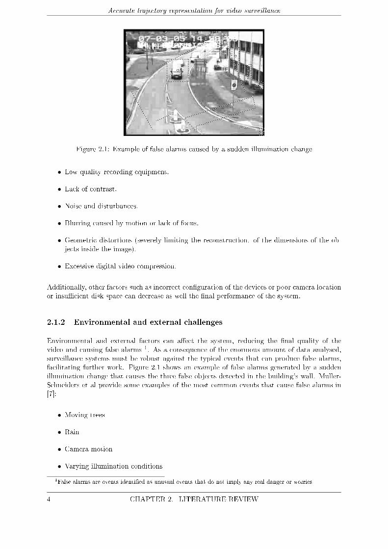
Figure 2.1: Example of false alarms caused by a sudden illumination change
• Low quality recording equipment.
• Lack of contrast.
• Noise and disturbances.
• Blurring caused by motion or lack of focus.
• Geometric distortions (severely limiting the reconstruction. of the dimensions of the ob-jects inside the image).
• Excessive digital video compression.
Additionally, other factors such as incorrect con�guration of the devices or poor camera locationor insu�cient disk space can decrease as well the �nal performance of the system.
2.1.2 Environmental and external challenges
Environmental and external factors can a�ect the system, reducing the �nal quality of thevideo and causing false alarms 1. As a consequence of the enormous amount of data analysed,surveillance systems must be robust against the typical events that can produce false alarms,facilitating further work. Figure 2.1 shows an example of false alarms generated by a suddenillumination change that causes the three false objects detected in the building's wall. Muller-Schneiders et al provide some examples of the most common events that cause false alarms in[7]:
• Moving trees
• Rain
• Camera motion
• Varying illumination conditions
1False alarms are events identi�ed as unusual events that do not imply any real danger or worries
4 CHAPTER 2. LITERATURE REVIEW

Accurate trajectory representation for video surveillance
Figure 2.2: Classic structure of a background subtraction algorithm
2.2 Motion Analysis Component
The primary task of video surveillance systems is the identi�cation of moving objects. Surveil-lance systems must be capable of detect and separate target objects (frequently vehicles andpedestrians) from the inanimate objects and the environment. Most of the systems use a combi-nation of spatial segmentation and temporal segmentation (tracking) to extract the objects. Thetask of the spatial segmentation algorithm is to discriminate between the pixels belonging to theobjects and the rest of the image. Usually, pixels belonging to the moving objects are known asforeground while the rest are considered as background. Therefore, the spatial segmentation al-gorithm classi�es every pixel of every frame in the video as foreground or background. The nextstep is to �nd the relation of the pixels between frames, establishing which pixels belong to thesame object from frame to frame. This is known as object tracking. The principal segmentationand tracking techniques are presented in the following paragraphs.
2.2.1 Spatial segmentation
In the case of static cameras (the case of our databases), the spatial segmentation usually consistsin a background subtraction algorithm. Background subtraction algorithms extract the relevantinformation from the video (foreground), removing the quasi-constant background and reducingthe amount of resources necessary to analyse the video. Background subtraction techniques arebased in the generation of a model to represent the background. Each frame of the video withbe compared against the simulated model to extract the foreground. Therefore, the foregroundis the sum of all the detected pixels that have been found to be di�erent from the implementedbackground model.The most common problems that can a�ect to the performance of the background subtractionalgorithm are related to the maintenance of the background model and real-time needs [8, 9]. Inthe following paragraphs, the most common problems that a�ect to the background maintenancewill be presented:
• Moved objects: sometimes background objects are moved by external factors like wind inthe case of the trees. These objects should not be consider part of the foreground.
• Time of the day: gradual changes in ambient illumination alter the appearance of thebackground
• Light switch: sudden changes in illumination due to light switching (indoor scenes) ormoving clouds (outdoor scenes) change the appearance of the background.
• Camou�age: some objects pixels characteristics may be similar to the background.
• Bootstrapping: some background techniques require a training period that may be notavailable in some environments, thus generating a background model in�uenced by fore-ground information.
CHAPTER 2. LITERATURE REVIEW 5
Accurate trajectory representation for video surveillance
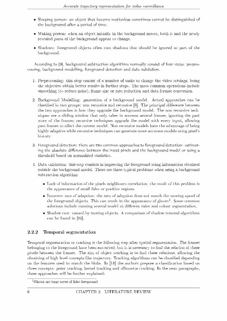
• Sleeping person: an object that became motionless sometimes cannot be distinguished ofthe background after a period of time.
• Waking person: when an object initially in the background moves, both it and the newlyrevealed parts of the background appear to change.
• Shadows: foreground objects often cast shadows that should be ignored as part of thebackground.
According to [9], background subtraction algorithms normally consist of four steps: prepro-cessing, background modelling, foreground detection and data validation.
1. Preprocessing: this step consist of a number of tasks to change the video settings, beingthe objective obtain better results in further steps. The most common operations includesmoothing (to reduce noise), frame size or rate reduction and data format conversion.
2. Background Modelling: generation of a background model. Actual approaches can beclassi�ed in two groups: non-recursive and recursive [9]. The principal di�erence betweenthe two approaches is how they upgrade the background model. The non-recursive tech-niques use a sliding-window that only takes in account several frames, ignoring the paststory of the frames; recursive techniques upgrade the model with every input, allowingpast frames to a�ect the current model. Non recursive models have the advantage of beinghighly adaptive while recursive techniques can generate more accurate models using pixel'shistory.
3. Foreground detection: there are two common approaches to foreground detection: estimat-ing the absolute di�erence between the input pixels and the background model or using athreshold based on normalized statistics.
4. Data validation: this step consists in improving the foreground using information obtainedoutside the background model. There are three typical problems when using a backgroundsubtraction algorithm:
• Lack of information of the pixels neighbours correlation: the result of this problem isthe appearance of small false or positive regions.
• Incorrect rate of adaption: the rate of adaption does not match the moving speed ofthe foreground objects. This can result in the appearance of ghosts2. Some commonsolutions include running several model at di�erent rates and colour segmentation.
• Shadow cast: caused by moving objects. A comparison of shadow removal algorithmscan be found in [10].
2.2.2 Temporal segmentation
Temporal segmentation or tracking is the following step after spatial segmentation. The framesbelonging to the foreground have been extracted, but it is necessary to �nd the relation of thesepixels between the frames. The aim of object tracking is to �nd these relations, allowing theobtaining of high level concepts like trajectory. Tracking algorithms can be classi�ed dependingon the features used to match the blobs. In [11] the authors propose a classi�cation based onthree concepts: point tracking, kernel tracking and silhouette tracking. In the next paragraphs,these approaches will be further explained:
2Ghosts are large areas of false foreground
6 CHAPTER 2. LITERATURE REVIEW
Accurate trajectory representation for video surveillance
• Points: The detected objects are represented by points. The association of the pointsis done with the information of the previous object state. This method requires an ex-ternal detector to detect the objects in every frame. This techniques can be divided indeterministic models and statistical models.
� Deterministic models: deterministic methods de�ne a cost of associating each objectin frame t − 1 to a single object in frame t using a set of motion constraints. Min-imization of the cost is formulated as a combinatorial optimization problem. Usedconstraints include proximity, maximum speed or common movement.
� Statistical models: use the state space approach to model the object properties such asposition, velocity, and acceleration. These measurements are used to predict object'sposition. Some of the most important statistical methods include Kalman �lter,particles �lter or multiple hypotheses tracking (MHT).
• Kernel: kernel is related to the objects shape and appearance. Objects are tracked bycalculating the motion of the kernel in consecutive frames. These techniques can be dividedin two groups:
� Template and density-based techniques: these techniques perform the matching bycomparing a template or a de�ned geometric shape of the detected foreground in thecurrent frame. Widely used due to their low computational cost.
� Multi-view techniques: use di�erent views of an object to perform the tracking.
• Silhouette: these algorithms estimate the object region in each frame. Silhouette tech-niques can be classi�ed in two subgroups:
� Contour evolution: iteratively evolves an initial contour adapting to the new object'sposition.
� Shape matching: looks for a concrete shape in each frame by comparing the existingones with the modelled shape. This model is upgraded regularly.
2.3 Occlusion handling
One of the main challenges in video surveillance systems is the problem of occlusions in videosequences. Occlusion occurs when an object is not visible in a frame because other object orstatic structure is blocking its view. The problem of occlusion is normally treated as a trackingissue, as position and velocity of an occluded object are di�cult to determine. However, someauthors propose parallel or post-tracking occlusion handling techniques in the case the trackingalgorithm is not robust enough or cannot deal with occlusions [12, 13]. Javed and Shah di�erencethree types of occlusions [1]:
• Inter-object occlusion: an object blocks the view of other objects in the visual �eld of thecamera. An special case in inter-object occlusion is when objects are entering/leaving the�lmed area. Since people usually move in groups, which results in frequent inter-objectocclusion so detecting and resolving inter-object occlusion is important for surveillanceapplications. Moreover, tra�c monitoring applications must deal also with lots of inter-object occlusions.
• Occlusion of objects due to thin structures: poles or trees can split the detected object intwo di�erent regions. This problem is aggravated when multiple objects are occluded bythe same structure.
CHAPTER 2. LITERATURE REVIEW 7
Accurate trajectory representation for video surveillance
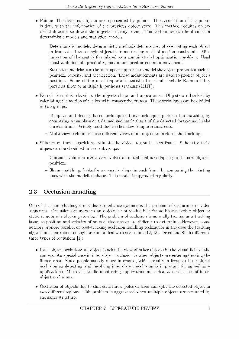
Figure 2.3: Example of occlusion provided by [1]
• Occlusion of objects due to large structures: the object disappears for a certain amountof time. It is necessary to determine the possibility of reappearance and exit of the scene.This type of occlusion is quite common in videos �lmed in outdoor areas such as streetsor parks.
Other proposed occlusion classi�cations based on tracking include additional types such asapparent occlusions or self-occlusions [14]. A brief study of the some of the most commonapproaches to occlusion solving can be found in [15]. All the techniques mentioned in the workare tracking approaches, the most relevant are the following:
• Usage of a ground plane representation combined with an estimation of the object size.
• The addition of an extra pixel model characterizing occlusion pixels, hence, using threedi�erent models: foreground pixels, background pixels and foreground occluding pixels.
• Learning a model of scene occlusions from the track of moving agents using minimumdescription length. This model creates successively more detailed models by dividing thescene into layers.
• Modelling of occlusion location based on a classi�cation of long-term, short-term andborder occlusions.
Scene modelling can be useful for occlusion handling (specially with entering/leaving objects)and can be implemented along with the occlusion prevention algorithm. In [16] Stau�er describesa method based on modelling entrances and exits with Gaussian Mixture Models (GMM).Thetechniques based on post-tracking processing must resolve the problem of the missing informa-tion. Ivanov et al [12] use an interpolation algorithm to �ll in the blank space.
2.4 Trajectory processing
As mentioned in the section Principal challenges in video surveillance systems, there are severalproblems to deal with in an video surveillance system. One of the main problems, occlusion,was explained in the section before along with the most representative techniques used to solveit. However, most of the e�ort for trajectory representation and classi�cation is spent in several
8 CHAPTER 2. LITERATURE REVIEW
Accurate trajectory representation for video surveillance
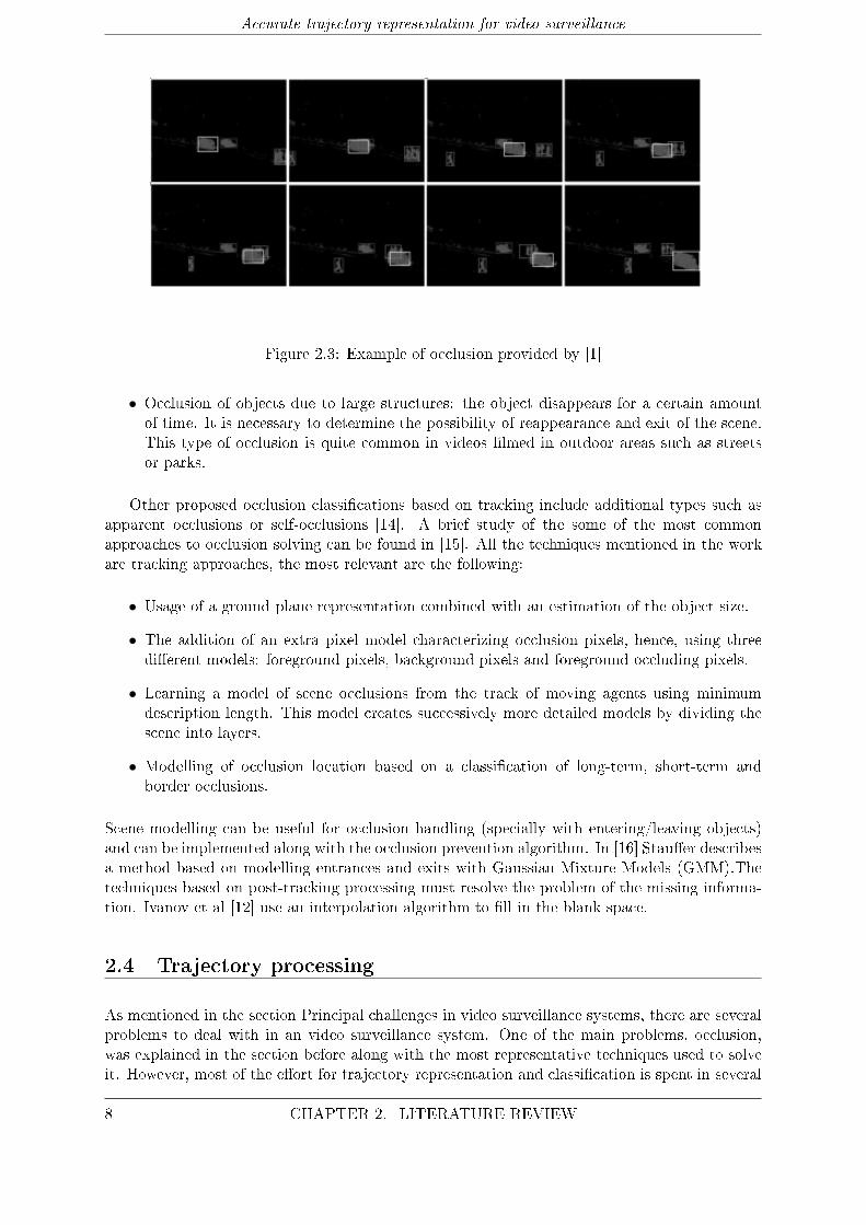
Figure 2.4: Summary of the principal techniques in trajectory processing
di�erent operations to adapt raw trajectories to a more desirable form. Usually, two di�erentproblems are taken into account: excessive spatial variation due to noise and issues related tothe tracker technique; and unequal length caused by the time-varying nature of the trajectories.The �rst problem a�ects directly to the quality of the detected paths and complicates furtheroperations. One of the most common approaches to solve this problem is data smoothing.The second problem must be solved to allow the application of clustering techniques, whichnormally require equal length in input data. Most researches use a combination of trajectorynormalization and dimensionality reduction in order to prepare raw trajectories for clustering.
2.4.1 Data smoothing
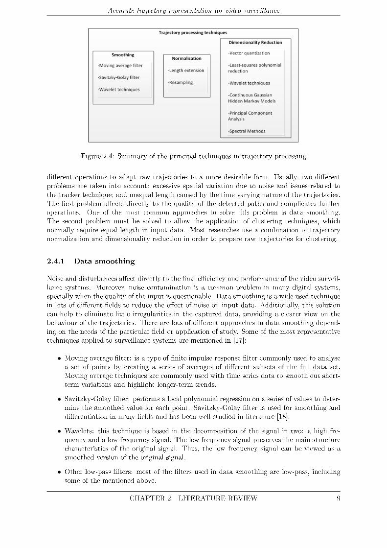
Noise and disturbances a�ect directly to the �nal e�ciency and performance of the video surveil-lance systems. Moreover, noise contamination is a common problem in many digital systems,specially when the quality of the input is questionable. Data smoothing is a wide used techniquein lots of di�erent �elds to reduce the e�ect of noise on input data. Additionally, this solutioncan help to eliminate little irregularities in the captured data, providing a clearer view on thebehaviour of the trajectories. There are lots of di�erent approaches to data smoothing depend-ing on the needs of the particular �eld or application of study. Some of the most representativetechniques applied to surveillance systems are mentioned in [17]:
• Moving average �lter: is a type of �nite impulse response �lter commonly used to analysea set of points by creating a series of averages of di�erent subsets of the full data set.Moving average techniques are commonly used with time series data to smooth out short-term variations and highlight longer-term trends.
• Savitzky-Golay �lter: performs a local polynomial regression on a series of values to deter-mine the smoothed value for each point. Savitzky-Golay �lter is used for smoothing anddi�erentiation in many �elds and has been well studied in literature [18].
• Wavelets: this technique is based in the decomposition of the signal in two: a high fre-quency and a low frequency signal. The low frequency signal preserves the main structurecharacteristics of the original signal. Thus, the low frequency signal can be viewed as asmoothed version of the original signal.
• Other low-pass �lters: most of the �lters used in data smoothing are low-pass, includingsome of the mentioned above.
CHAPTER 2. LITERATURE REVIEW 9
Accurate trajectory representation for video surveillance
2.4.2 Normalization
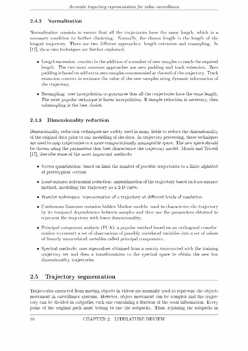
Normalization consists in ensure that all the trajectories have the same length, which is anecessary condition to further clustering. Normally, the chosen length is the length of thelongest trajectory. There are two di�erent approaches: length extension and resampling. In[17], these two techniques are further explained:
• Length extension: consists in the addition of a number of new samples to reach the requiredlength. The two most common approaches are zero padding and track extension. Zeropadding is based on add extra zero samples concatenated at the end of the trajectory. Trackextension consists in estimate the value of the new samples using dynamic information ofthe trajectory.
• Resampling: uses interpolation to guarantee that all the trajectories have the same length.The most popular technique is linear interpolation. If sample reduction is necessary, thensubsampling is the best choice.
2.4.3 Dimensionality reduction
Dimensionality reduction techniques are widely used in many �elds to reduce the dimensionalityof the original data prior to any modelling of the data. In trajectory processing, these techniquesare used to map trajectories to a more computationally manageable space. The new space shouldbe chosen using the parameters that best characterize the trajectory model. Morris and Trivedi[17], describe some of the most important methods:
• Vector quantization: based on limit the number of possible trajectories to a �nite alphabetof prototypical vectors.
• Least-squares polynomial reduction: approximation of the trajectory based on least squaresmethod, modelling the trajectory as a 2-D curve.
• Wavelet techniques: representation of a trajectory at di�erent levels of resolution.
• Continuous Gaussian emission hidden Markov models: used to characterize the trajectoryby its temporal dependencies between samples and then use the parameters obtained torepresent the trajectory with lower dimensionality.
• Principal component analysis (PCA): a popular method based on an orthogonal transfor-mation to convert a set of observations of possibly correlated variables into a set of valuesof linearly uncorrelated variables called principal components.
• Spectral methods: uses eigenvalues obtained from a matrix constructed with the trainingtrajectory set and then a transformation to the spectral space to obtain the new lowdimensionality trajectories.
2.5 Trajectory segmentation
Trajectories extracted from moving objects in videos are normally used to represent the objectsmovement in surveillance systems. However, object movement can be complex and the trajec-tory can be divided in subpaths, each one containing a fraction of the total information. Everypoint of the original path must belong to one the subpaths. Thus, rejoining the subpaths in
10 CHAPTER 2. LITERATURE REVIEW
Accurate trajectory representation for video surveillance
chronological order must result in obtaining the original trajectory. The criteria used to dividethe trajectory can be of spatial or temporal nature. The segmentation algorithm detects thepoints where there is a change in the motion such as a direction change or a speed increment.Consequently, each subpath represents a portion of the trajectory in which motion features re-main constant or quasi-constant.The main advantage of trajectory segmentation is the simpli�cation of further analysis, usingsubpaths instead of the complete trajectory. Moreover, as each subpath represents a concretepart of the total movement, is easier to extract and isolate particular behaviours. This informa-tion can be used in combination with the analysis of the complete trajectory, obtaining a morerobust model. Trajectory segmentation can be also used to obtain a reduced dimensionalitymodel, using the transition points between subpaths as the new trajectory points. Althoughthis simpli�cation means that the original points cannot be recovered, interpolation can be usedif is necessary to increment the number of points of the trajectory. The procedure to detect thepoints where there is a signi�cant change in the spatio-temporal characteristics of the trajectory,known as breakpoints, is normally based on geometrical and temporal analysis. Despite someof the surveillance systems and applications based on trajectories do not use a segmentationphase, several authors include this step in their systems with promising results. Piotto et al [2]propose a system based in three di�erent algorithms. After the segmentation, breakpoints arecharacterized by a set of features and then mapped to a syntactic alphabet. This leads to asimple matching step that can be used in high level applications such as automatic detection ofanomalous events. The authors classify the breakpoints in two types:
• Temporal breakpoints: detect sharp velocity discontinuities in the object motion. In par-ticular, this breakpoints are useful to detect stops/re-start events in the trajectory.
• Spatial breakpoints: denote changes in the direction of the object. In this category, isnecessary to distinguish between short-term variations and long-term variations using adi�erent algorithm for each type.
Bashir et al [19] use curvature changes in trajectory to segment the paths, and then PCA torepresent the subpaths. The subpaths are grouped using clustering and then a HMM represen-tation to build a motion recognition system.
2.6 Trajectory representation
Trajectory representation techniques are often used in high level applications to facilitate pro-cedures like clustering and matching. There are several approaches to obtain a more robust ande�cient model. Moreover, a good representation strategy should be able to highlight similaritiesand di�erences between trajectories, as same spatial trajectories could be associated to di�erentmotion patterns. Basically, there are two approaches to trajectory representation. On the �rsthand, some authors use a set of features to represent the main characteristics of the trajecto-ries, applying in some cases a transformation to the obtained features to improve robustness orreduce dimensionality [20, 12, 2]. On the other hand, some others, use direct transformationson trajectories such as PCA [19]. Porikli and Haga propose a feature classi�cation in [20]. Thisclassi�cation divides the features in two groups: object-based features and frame-based features.The �rst type describes properties of individual objects while the latter represents the propertiesof a frame using the properties of objects existing in the frame. The main features described ineach group are the following:
CHAPTER 2. LITERATURE REVIEW 11
Accurate trajectory representation for video surveillance
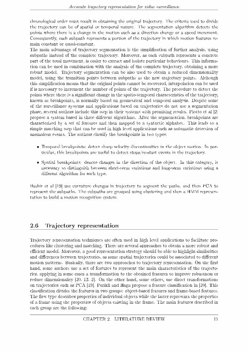
Figure 2.5: Summary of the principal features used in trajectory representation
• Object-based features
� Histograms: aspect radio, slant, orientation, speed, colour, size.
� HMM's: features transferred to a parameter space λ that is characterized by a set ofHMM parameters. This type includes: coordinate, orientation, speed.
� Scalar: duration, length, displacement, global direction.
• Frames-based features
� Histograms: orientation, location, speed.
� Scalar: number of objects, size.
To reduce the high dimensionality of most of the proposed features, the authors use an eigenvec-tor decomposition on the similarity feature matrices. Recent work with this type of features hasbeen developed by several authors. The following paragraph describes some of these approaches:Ivanov et al [12] propose a representation based on model every trajectory with high level fea-tures such as velocity and acceleration. These features are re-sampled to ensure the same lengthfor all the trajectories and then fed to a SVM system for training. In [2], the authors proposealso a system based in features extraction. Nevertheless, features extraction is done for everybreakpoint calculated in a previous step. The features used are angle, velocity and duration.Then, these parameters are quantized and prepared for the matching procedures.Bashir et al [19] estimate the PCA coe�cients of the previously obtained subpaths to representthe trajectories in an accurate and compact way. To achieve invariance, input trajectories are�rst low-pass �ltered and normalized. Other common approaches to dimensionality reductionused in trajectory representation can be found in Section 2.4.3.
12 CHAPTER 2. LITERATURE REVIEW
3System design and development
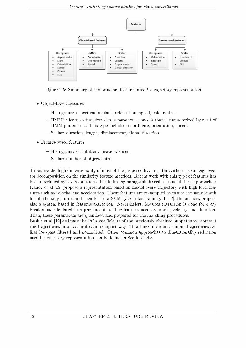
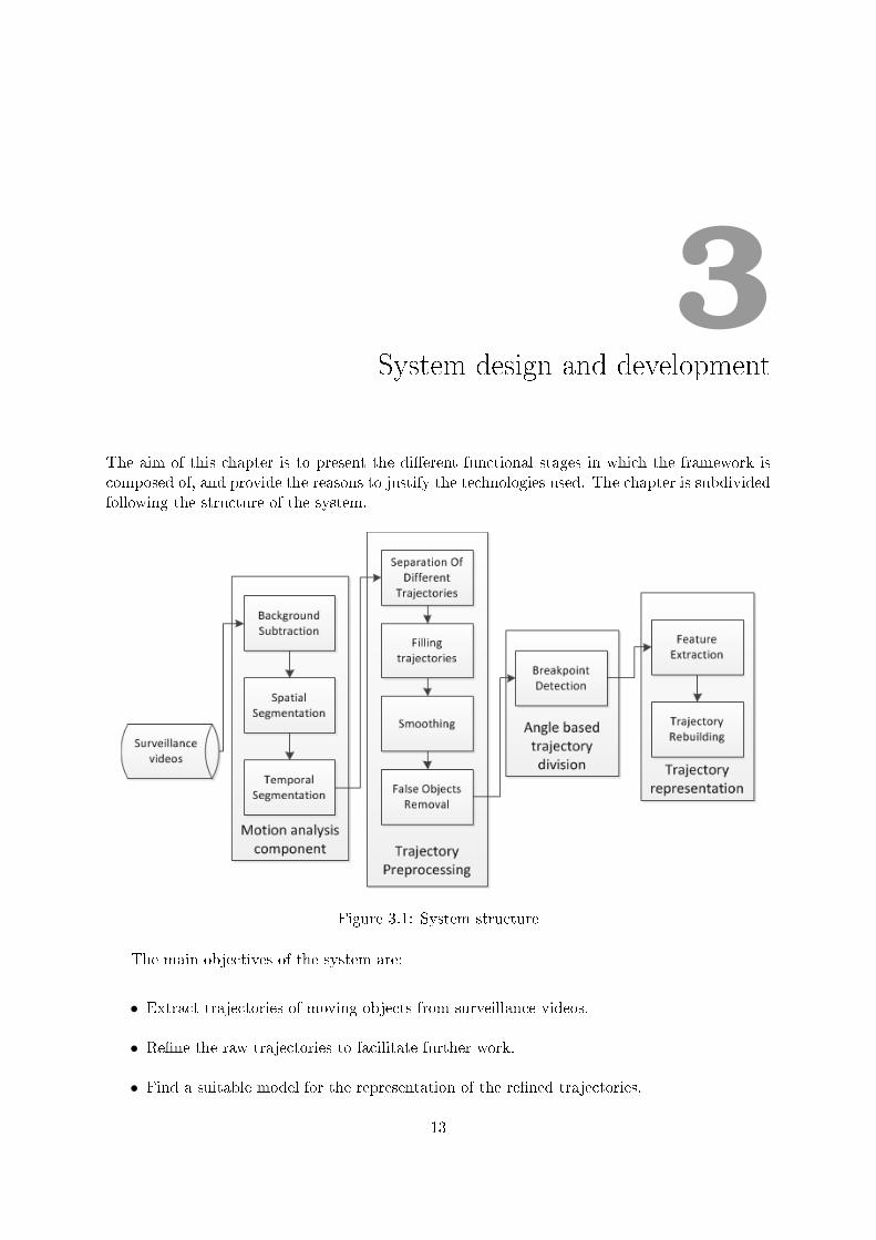
The aim of this chapter is to present the di�erent functional stages in which the framework iscomposed of, and provide the reasons to justify the technologies used. The chapter is subdividedfollowing the structure of the system.
Figure 3.1: System structure
The main objectives of the system are:
• Extract trajectories of moving objects from surveillance videos.
• Re�ne the raw trajectories to facilitate further work.
• Find a suitable model for the representation of the re�ned trajectories.
13
Accurate trajectory representation for video surveillance
The project is divided in four main stages: motion analysis component, trajectory preprocessing,angle-based trajectory division and trajectory representation. All the proposed techniques andalgorithms have been implemented in C/C++.
1. Motion Analysis Component (section 3.1) receives the surveillance video and detectsthe moving objects in the video, providing the raw trajectories that will be further anal-ysed in the next steps. The objects in the video are spatially and temporally segmentedto remove the non-relevant information, basically the parts of the frames not belongingto the objects, therefore reducing the amount of the information that will be analysed.Thus, the motion analysis component yields a background subtraction method, an objectsegmentation algorithm and an object tracker. The information provided includes the size,coordinates of the centroid and frame numbers where the detected objects appear.
2. Trajectory preprocessing stage (section 3.2) although the motion analysis componentis based on a robust technique, some matters like noise and occlusions can lead to amore di�cult and less accurate results in the next steps. Consequently, is essential toenhance this data. Several operations are de�ned in this step: separation of mismatchedtrajectories1, joining the subpaths of a trajectory split by occlusions, a smooth step basedin Saviztky-Golay �lters and a �nal false object2 removal step.
3. Angle based trajectory division stage (section 3.3) consists in the separation of eachtrajectory into several subpaths. Trajectories are scanned to �nd the points where thereis an important spatial or temporal change, that is, the breakpoints.
4. Trajectory representation (section 3.4) once the breakpoints have been calculated, thenext step is to extract the features that characterize the subpaths existing between break-points. Finally, these features can be used to reconstruct the subpaths. The aim of thisstage is to procure a method to model and represent trajectories which have been previ-ously pre-processed.
In the following paragraphs each of the presented stages will be further detailed along with thetechniques applied in each stage.
3.1 Motion Analysis Component
The �rst stage of our framework is the Motion Analysis Component. Its objective is the ex-traction of the moving objects that appear in the surveillance videos. Relevant information iscontained in the movement objects such as vehicles or pedestrians, while the background remainsquasi-constant in time. Therefore, it is necessary to separate the foreground objects from thebackground to allow the analysis of this information. Moreover, this process leads to low com-putational cost and faster procedures, reducing the amount of information processed. However,some operations like resizing and changing the input video format are necessary before start-ing the analysis. The stages that compose the Motion Analysis Component are the following:preprocessing operations, background subtraction algorithm, spatial segmentation and objecttracking.
1Mismatched trajectories are trajectories that belong to di�erent objects but have been merged by the tracker
algorithm as if they belong to the same object.2False objects are detected objects not extracted from the detection of a real object but created by noise or
other disturbances.
14 CHAPTER 3. SYSTEM DESIGN AND DEVELOPMENT
Accurate trajectory representation for video surveillance
• Input preprocessing step grants that the input video will match the system requirementsof size and format. A video edition tool is used to change the video parameters.
• Background modelling is necessary to separate foreground objects from the background.The technique used is based in modelling the background as a mixture of Gaussians.
• Object detection step �nds out the spatial nexus of the detected foreground pixels ineach frame. The method used is a two-pass connected component algorithm based on a8-neighbour connection.
• Object tracking provides the relation of the objects detected between di�erent frames. Theimplemented solution is based on a linearly predictive multi-hypothesis tracking algorithm.
The Motion Analysis Component fundamentals and steps are explained in further detail in thenext paragraphs.
3.1.1 Background subtraction algorithm
In this step,the objective is to calculate a mathematical background model, based in the workof Stau�er and Grimson [21]. This approach provides an adaptive background subtraction tech-nique that deals robustly with illumination changes, slow moving objects and other externalproblems that a�ect typically to background subtraction procedures. This method is also suit-able for working on real-time applications using low resolutions. In the approach of Stau�erand Grimson [21], the separation between the foreground of an image and the background isperformed by modelling the background as a mixture of Gaussians. Stationary objects are con-sidered as part of the background, while moving objects are subscribed to the foreground.For a particular pixel, the probability of belonging to the background or the foreground is cal-culated based on the persistence and the variance of each of the Gaussians of the mixture.Furthermore, this value is directly related to the intensity and colour distribution of the pixel inthat certain image. As a result of this method, each pixel is classi�ed, considering foregroundpixels those which do not �t any background distribution. Due to possible light changing con-ditions, the model must be based in adaptive Gaussians. The main advantages of adaptiveGaussians are: the robustness against external changes and the capacity of deal with sleep walk-ing objects. The later advantage comes from the fact that the previous background still existsbut with a lower ω.The recent history of each pixel is modelled as a mixture of K Gaussian distributions. Theprobability of observing the current pixel value is:
P (Xt) =K∑i=1
ωi,t ∗ η (Xt, µi,t, εi,t) (3.1)
where K is the number of distributions; ωi,t is an estimate of the weight of the ith Gaussian inthe mixture at time t; µi,t and εi,t are the mean value and covariance matrix of the ith Gaussianin the mixture at time t; and η is a Gaussian probability density function. Every time a newpixel value Xt is obtained, this value is checked against the existing K Gaussian distributionsuntil a match is found. In this process, the authors de�ne match as a pixel value within 2.5standard deviations of the checked distribution. Nevertheless, in the case of mismatch, the leastprobable distribution is replaced with a new distribution, using the current value as its meanvalue, and an initially high variance and low prior weight.Once the pixel has been classi�ed its model needs to be adjusted, thus, the weight, average and
CHAPTER 3. SYSTEM DESIGN AND DEVELOPMENT 15

Accurate trajectory representation for video surveillance
Figure 3.2: Object segmentation method example
variance are updated following the formulae 3.2, 3.3, 3.4 and 3.5.
ωk,t = (1− α)ωk,t−1 + α (Mk,t) (3.2)
where α is the learning rate and Mk,t is the result of the pixel classi�cation (1 when the modelis matched and 0 otherwise).
µt = (1− ρ)µt−1 + ρXt (3.3)
σ2t = (1− ρ)σ2t−1 + ρ (Xt − µt)T (Xt − µt) (3.4)
where ρ
ρ = αη (Xt|µk, σk) (3.5)
In the case of mismatch, only the weights are updated.
3.1.2 Spatial segmentation
After the pixels are classi�ed, foreground pixels are grouped using a two-pass connected com-ponents algorithm. The algorithm scans the image until it �nds a pixel classi�ed as foreground.Each pixel has a label attached to it; zero if belongs to the background and an integer otherwise.Then, basing on the label of the four neighbours that have been already scanned the pixel isupdated as foreground or background. After the �rst pass, the scan is repeated again becausethe connected components algorithm is two-pass. Furthermore, each label is associated with aclass, in the form of an identi�cation number. This number is replaced by its equivalent labelduring the second scan. Hence, foreground objects are segmented spatially in every frame of thevideo.
16 CHAPTER 3. SYSTEM DESIGN AND DEVELOPMENT
Accurate trajectory representation for video surveillance
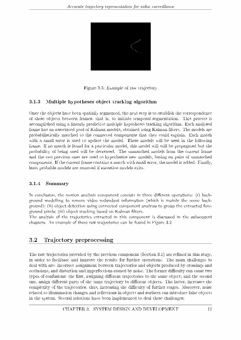
Figure 3.3: Example of raw trajectory
3.1.3 Multiple hypotheses object tracking algorithm
Once the objects have been spatially segmented, the next step is to establish the correspondenceof these objects between frames, that is, to initiate temporal segmentation. This process isaccomplished using a linearly predictive multiple hypotheses tracking algorithm. Each analysedframe has an associated pool of Kalman models, obtained using Kalman �lters. The models areprobabilistically matched to the connected components that they could explain. Each matchwith a small error is used to update the model. These models will be used in the followingframe. If no match is found for a particular model, this model will still be propagated but theprobability of being used will be decreased. The unmatched models from the current frameand the two previous ones are used to hypothesize new models, basing on pairs of unmatchedcomponents. If the current frame contains a match with small error, the model is added. Finally,least probable models are removed if excessive models exist.
3.1.4 Summary
In conclusion, the motion analysis component consists in three di�erent operations: (i) back-ground modelling to remove video redundant information (which is mainly the scene back-ground); (ii) object detection using connected component analysis to group the extracted fore-ground pixels; (iii) object tracking based on Kalman �lters.The analysis of the trajectories extracted in this component is discussed in the subsequentchapters. An example of these raw trajectories can be found in Figure 3.3
3.2 Trajectory preprocessing
The raw trajectories provided by the previous component (Section 3.1) are re�ned in this stage,in order to facilitate and improve the results for further operations. The main challenges todeal with are: incorrect assignment between trajectories and objects produced by crossings andocclusions, and distortion and imperfections caused by noise. The former di�culty can cause twotypes of confusions: the �rst, assigning di�erent trajectories to the same object; and the secondone, assign di�erent parts of the same trajectory to di�erent objects. The latter, increases thecomplexity of the trajectories, thus, increasing the di�culty of further stages. Moreover, noiserelated to illumination changes and re�ections in objects and surfaces can introduce false objectsin the system. Several solutions have been implemented to deal these challenges:
CHAPTER 3. SYSTEM DESIGN AND DEVELOPMENT 17
Accurate trajectory representation for video surveillance
1. Separation of objects with di�erent trajectories is the �rst stage of the trajectorypreprocessing component. To deal with the matter of di�erent trajectories assigned to thesame object, raw trajectories are analysed and split if the one of the conditions (furtherexplained in Subsection 3.2.1) is ful�lled.
2. Joining of trajectories that belong to the same object. The main cause of thedivision of some of the trajectories in the videos into several subpaths are occlusions andcrossings caused by obstacles and other objects. The technique proposed to solve this isbased in Bresenham's line drawing algorithm (see subsection 3.2.2 for more details).
3. Trajectory smoothing is the third stage of the trajectory preprocessing component. Theaim of this stage is reduce the noise and imperfection of the raw trajectories. The methodimplemented is based in Saviztky-Golay �lter (details in subsection 3.2.3 ).
4. False objects removal is the last stage. In order to eliminate the false objects introducedby noise e�ects, the objects that have been smoothed have to ful�l a number of conditions(details in subsection 3.2.4 ).
3.2.1 Separation of objects with di�erent trajectories
Sometimes, when two objects pass near each other or their paths cross, the motion analysiscomponent assigns the paths as belonging to the same object. Therefore, it is necessary toanalyse raw trajectories to �nd and separate the di�erent paths. A set of conditions is de�nedto determine when a trajectory should be divided. These conditions are strictly spatial, notemporal information is considered, because the paths involved are always consecutive in time.The conditions are the following:
1. Distance between two consecutive points: the distance is de�ned as the Euclideandistance:
εn =
√(xn+1 − xn)2 + (yn+1 − yn)2 (3.6)
If εn exceeds a pre-de�ned threshold ε the condition is satis�ed and the object divided.
2. Angle β (de�ned in Beta breakpoints 3.3.2) condition is satis�ed if the angle exceedsthe threshold α1. The election of the threshold is based on the idea that moving objectsextracted from surveillance videos rarely change abruptly their direction.
3.2.2 Joining of trajectories that belong to the same object
Occlusion is one of the main problems when working with video surveillance videos. Pedestriansand cars often get occluded by a number of static obstacles like tra�c lights, trees or postingsigns. In addition to these obstacles, other targets can produce the same e�ect when passing overthe focused object. As a result, the trajectories are split into several others, not representing thereal behaviour of the object. To detect occlusions, the system compares each trajectory with allthe others, and if they satisfy a number of conditions, the trajectories are joined:
• Spatio-temporal proximity: the distance between the last point of the �rst pathP 1end(the one that goes before in time) and the �rst point of the second path P 2
beg, must
18 CHAPTER 3. SYSTEM DESIGN AND DEVELOPMENT

Accurate trajectory representation for video surveillance
Figure 3.4: Bresenham's algorithm
be under than a prede�ned number N (the measure of distance is the same as in Formula3.6). In addition to this, the di�erence between the number of the frame of P 1
end and P2beg
cannot exceed F . This conditions ensures that only spatio-temporal close paths can bejoined.
• Similar direction: this condition is similar to the beta angle condition of the previousstage, but in an opposite way. The end of the �rst path and the beginning of the secondone are analysed using the same formula as in 3.2.1. The condition is satis�ed if thevalue obtained is below a prede�ned threshold α2. This condition prevent the system fromjoining paths of di�erent crossing objects that would probably satisfy the rest of conditions.
• Consecutive paths: to ensure the second path is consecutive in time, the number offrame in which appears the last point of the �rst path (F 1
end) must be smaller than thenumber of frame of the �rst point of the second path (F 2
beg). Non temporally consecutivepaths cannot belong to the same object.
• Similar size: for each path, an average size is calculated. A maximum increment ∆S isde�ned, discarding the compared paths that overcome that value. This condition avoidsthe system from joining paths from di�erent objects that have satis�ed the spatio-temporalproximity condition ignoring the e�ect of the image depth. This e�ect can be detectedcomparing the size of the objects. Additionally, can help to avoid joining di�erent kind ofobjects, for example pedestrians and cars.
Whenever two trajectories are joined, there is always an empty gap between them. The missingtrajectory segment is completed using the �lling process described in [12]. This process is basedin the Bresenham's line drawing algorithm [22], whose operation principles are fully detailed thenext paragraphs.
Bresenham's drawing algorithm
The Bresenham drawing algorithm determines which points in a n-dimensional space should beselected to form the line between two given points. The principal advantages of the algorithmare its simplicity and its low computational cost (as it uses only cheap computational operationssuch as integer addition, integer subtraction and bit shifting). Our implementation of Bresen-ham's line drawing algorithm is described in the following paragraphs.The �rst stage is the initialization of the variables used by the algorithm. The �rst operation isto calculate the variables dx and dy:
dx = x1 − x0 (3.7)
dy = y1 − y0 (3.8)
CHAPTER 3. SYSTEM DESIGN AND DEVELOPMENT 19

Accurate trajectory representation for video surveillance
Figure 3.5: Comparison between pre-smoothing trajectory (left) and post-smoothing trajectory(right)
where (x0, y0) are the coordinates of the initial point and (x1, y1) represent the coordinates ofthe �nal point The values obtained are used to calculate inc:
inc = 2 ∗ dy − dx (3.9)
The second part of the algorithm is a loop where the stopping criterion is to reach x = x1. Ineach iteration, the value of x is increased in a unit. The value of y can be updated depending oninc, which is also updated in each iteration. There are two di�erent possibilities: inc > 0 andinc <= 0. If inc > 0, y will be updated and the current point (x, y) will be extracted. Thenthe variable inc will be updated with the formula inc = inc+ (2 ∗ dy− 2 ∗ dx). In the case thatinc <= 0, y will not be updated and inc = inc+ 2 ∗ dy.
3.2.3 Trajectory smoothing
The object trajectories obtained after separation and �lling remain noisy and imperfect. Theobjective of the trajectory smoothing is to reduce the e�ects of illumination changes, noise andother imprecisions related to external factors . Besides, smoothing reduces the complexity of thetrajectories, facilitating representation as the number of features necessary to characterize themdecreases. A solution to smooth the trajectories obtained is presented in [12]. Authors proposean implementation based on Saviztky-Golay �lter. In the next paragraphs this �lter and itsimplementation are further explained ir order to facilitate the comprehension of the proposedsystem.
Saviztky-Golay �lter
Saviztky-Goaly �lter is based on the calculation of a polynomial regression to determine thevalue of each point. The �lter has three parameters: order, polynomial degree and length. Theorder of the �lter is the order of the nth derivative that the �lter would apply to the entrance(zero order is equal to smoothing). The polynomial degree is related to the polynomial regressionused to calculate the values of the �lter. Finally, the length of the �lter is the number of pointsof the �lter used, must be always an odd number and higher than the polynomial order. Thenumber of points of the trajectories must be at least the length of the �lter.For a certain order, �lter coe�cients are dependent on the polynomial degree and length. As thepolynomial degree decreases or the length increases, the noise variance is reduced, nonetheless
20 CHAPTER 3. SYSTEM DESIGN AND DEVELOPMENT
Accurate trajectory representation for video surveillance
this implies losing some details of the input signal [18]. The main advantage of the Saviztky-Golay �lter is that it tends to preserve the features of the distribution such as minima andmaxima relative values. According to the results obtained by Ivanov et al [12], the selection ofa proper polynomial order and window length leads to lower computational complexity and agood approximation of the trajectories. The parameters are set to the values proposed in [12]:polynomial degree p = 4 and length n = 21. Figure 3.5 shows the e�ects of the �ltering over araw trajectory with p = 4 and n = 21.The steps followed for the implementation of the �lter are described in the next paragraphs:
1. This �rst point consists in obtaining the matrix A. A is a matrix of nx(p + 1), where nis the length of the �lter and p is the polynomial degree. This matrix is calculated k + 1times, where k = n−1
2 , using the following formula:
Am = (OTm ∗Q)∀m = 1, 2...k + 1 (3.10)
where Om is a vector containing the numbers from (1−m) to (n−m) and Q is a vectorof (p+ 1) one values. Finally, each column of Am is raised to the (r− 1) power where r isthe number of that column.
2. The second step is �nding A+m the pseudo-inverse matrix of Am. The method used to
compute A+m is the single value decomposition (SVD) [23]. The single value decomposition
consists in a factorization of the form Am = Um ∗ Sm ∗ (V ∗m)T , where Un is a n x (p + 1)matrix, Sm is a diagonal matrix of (p + 1) x (p + 1) dimensions and Vm is a matrix of(p+ 1) x (p+ 1) dimensions. The implementation of the SVD method is mathematicallycomplex, consequently, our approach is based on the implementation described by Presset al [24]. Once the U , S and V matrices are calculated, the pseudo inverse is obtained bythe following operation:
A+m = Vm ∗ S+
m ∗ UTm (3.11)
where S+m, the pseudo inverse of a diagonal matrix, can be calculated by taking the recip-
rocal of each non-zero element on the diagonal and transposing the resulting matrix. The�rst row of the matrix A+
m corresponds to the mth row of the �lter, Fm.
3. The procedure presented in steps 1 and 2 is performed k + 1 times, thus, obtaining the�rst k + 1 rows of the �lter. The remaining rows from i = k + 2 to n are calculated byusing Fi = F inv
n−i−1, where Finv is the same matrix as F but with the values of the rows
sorted inversely.
3.2.4 False objects removal
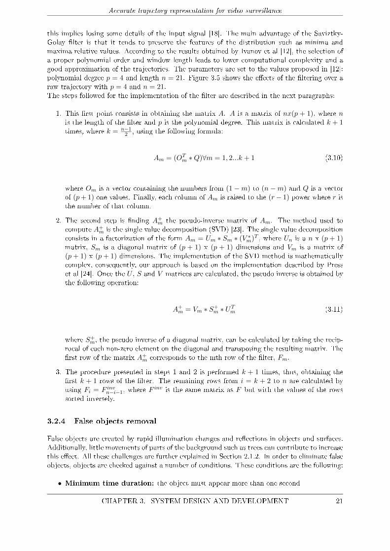
False objects are created by rapid illumination changes and re�ections in objects and surfaces.Additionally, little movements of parts of the background such as trees can contribute to increasethis e�ect. All these challenges are further explained in Section 2.1.2. In order to eliminate falseobjects, objects are checked against a number of conditions. These conditions are the following:
• Minimum time duration: the object must appear more than one second
CHAPTER 3. SYSTEM DESIGN AND DEVELOPMENT 21
Accurate trajectory representation for video surveillance
• Minimum number of points: the number of points of the trajectory (which is invariantduring the trajectory pre-processing) must be above a prede�ned minimum κ. False objecttrajectories are normally short due to its dependence to rapid and chaotic changes in noiseand illumination. Moreover, trajectories with a very short number of points provide littleor none information of the behaviour of the object. Consequently, trajectories with lesspoints than κ will be removed in this stage. κ is bounded below by the selected length ofthe Saviztky-Golay �lter (see Saviztky-Golay Filter 3.2.3).
• Minimum stroke: the object must change its position in more than a certain numberof pixels. The reason beneath this condition is that objects created by external factorsare normally stationary, moving little around the same position. The stroke conditionimplementation consists of a minimum distance from the initial point that the object mustovercome.
• Minimum size: the object must have a minimum size. Objects smaller than a pedes-trian should not be taken into consideration. Additionally, pedestrians smaller than acertain size cannot be distinguished as a moving object. Regarding this, a size thresholdis implemented. The value of the threshold is set experimentally.
3.2.5 Summary
The main objective of the presented section is to enhance the information obtained in the motionanalysis component. As previously stated, the trajectory preprocessing component consistsof: (i) Separation of objects with di�erent trajectories, to prevent several trajectories to bearti�cially joined in one object (ii) Joining of trajectories that belong to the same object, todeal with occlusion and split paths that belong to the same object; (iii) Trajectory smoothing,to remove noise and reduce the complexity of the trajectories; and �nally, (iv) False objectsremoval to eliminate objects arti�cially created by noise. After these operations, the resultingtrajectories pass to the next step.
3.3 Angle-based trajectory division
The main objective of this stage is to procure a method to divide trajectories which have beenpreviously preprocessed in several subpaths. In the videos, the objects change their movementin di�erent ways such as stops, deviations and turns. Hence, these changes are re�ected in theirtrajectories which evolve temporally and spatially. To represent trajectories, is easier to dividethem in several subpaths, trying to separate parts of the trajectory with di�erent behaviour.The points where trajectories change are known as breakpoints, and their detection is the �rststep for trajectory division. After the detection, trajectories are divided into several subpaths,each of them starting and �nishing in a breakpoint. Consequently, each subpaths represents apart of the trajectory with a di�erent behaviour compared to the ones before and after.In our approach, we di�erentiate three di�erent types of breakpoints: temporal, beta-spatial andgamma-spatial. Temporal breakpoints mark the points where the velocity of the object detectedis null, which often indicates a following change in the trajectory. Moreover, stops usually arerelated to external factors such as tra�c lights or meetings between peasants, thus, importantinformation for behaviour understanding.Spatial breakpoints denote changes in direction. These changes can be abrupt and local or cumu-lative and extended in a long period. Therefore, two di�erent criteria are implemented to detectthese deviations: beta breakpoints and gamma breakpoints. The breakpoints implemented inthe system are de�ned in [2]. In the next paragraphs, the di�erent types of breakpoints will befurther explained.
22 CHAPTER 3. SYSTEM DESIGN AND DEVELOPMENT
Accurate trajectory representation for video surveillance
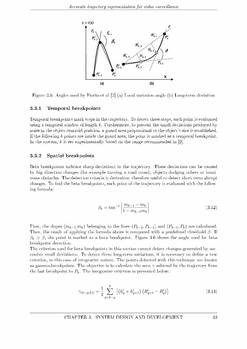
Figure 3.6: Angles used by Piotto et al [2] (a) Local variation angle (b) Long-term deviation
3.3.1 Temporal breakpoints
Temporal breakpoints mark stops in the trajectory. To detect these stops, each point is evaluatedusing a temporal window of length k. Furthermore, to prevent the small deviations produced bynoise in the object centroid position, a guard area proportional to the object's size is established.If the following k points are inside the guard area, the point is marked as a temporal breakpoint.In the system, k is set experimentally based on the range recommended in [2].
3.3.2 Spatial breakpoints
Beta breakpoints indicate sharp deviations in the trajectory. These deviations can be causedby big direction changes (for example turning a road cross), objects dodging others or inani-mate obstacles. The detection criteria is derivative, therefore useful to detect short-term abruptchanges. To �nd the beta breakpoints, each point of the trajectory is evaluated with the follow-ing formula:
βk = tan−1∣∣∣∣ mk−1 −mk
1−mk−1mk
∣∣∣∣ (3.12)
First, the slopes (mk−1,mk) belonging to the lines (Pk−2, Pk−1) and (Pk−1, Pk) are calculated.Then, the result of applying the formula above is compared with a prede�ned threshold β. Ifβk > β, the point is marked as a beta breakpoint. Figure 3.6 shows the angle used for betabreakpoint detection.The criterion used for beta breakpoints in this section cannot detect changes generated by suc-cessive small deviations. To detect these long-term variations, it is necessary to de�ne a newcriterion, in this case of integrative nature. The points detected with this technique are knownas gamma-breakpoints. The objective is to calculate the area γ subtend by the trajectory fromthe last breakpoint to Pk. The integrative criterion is presented below:
γ(k−g,k)) =1
2
k∑q=k−g
[(hiq + hiq+1
) (Ri
q+1 −Riq
)](3.13)
CHAPTER 3. SYSTEM DESIGN AND DEVELOPMENT 23
Accurate trajectory representation for video surveillance
As shown in Figure 3.6, r is the line that joins the last breakpoint with the point being evalu-ated Pk, (hiq is the distance between the trajectory and r, and Ri
k−g is the distance between theprojections of the trajectory points Pk−g and Pk−g+1 in r. Again, if γj > γ, the point is markedas a breakpoint. The values of β and γ are discussed in the next chapter.
3.3.3 Summary
The Angle based trajectory division stage is divided in two parts: (i) Temporal breakpoints and(ii) Spatial breakpoints. Each one is related to a di�erent type of breakpoint, and indicates adi�erent change detected in the trajectory. In the next section, the subpaths de�ned by thedetected breakpoints, are characterized by a set of features (angle, velocity, duration), used torepresent and rebuild the trajectories in an accurately and compact way.
3.4 Trajectory representation
According to the spatio-temporal analysis presented in the previous section Angle based trajec-
tory division, the trajectory can be described as a chain of breakpoints Bin ∀ n=1,2,...M (being
M the number of breakpoints for the ith object). Each pair of breakpoints, Bin, B
in+1, identi�es
a subpath Sij = (Bi
j , Bij+1) that approximates a portion of the original path. Consequently,
the trajectory can be represented by a description of the subpath chain. In our representation,based on [2], each subpath is characterized by three features: angle (Θi
j), duration (∆tij) andvelocity (νij). With these features it is possible to describe a wide variety of trajectories andperform di�erent analysis. Some examples include the identi�cation and representation of tra-jectories with similar spatial behaviour but di�erent speed, detection of sleep walker objects,discriminate between cars and pedestrians based on their velocity and moving patterns and thedetection of concrete behaviour patterns. Additionally, the implementation of the features issimple and compact, and the trajectory can be easily rebuilt from the feature values. In case thetemporal information is not relevant, the samples with null velocity can be dropped, obtaining apure geometric representation. Moreover, duration and velocity can be merged to form a morecompact representation if looking only for spatial information.The implemented representation is inherently invariant to rotation and translation. Only thecoordinates and orientation of the �rst segment refer to an absolute positioning (the �rst pointis always necessary to rebuild the trajectory), but this information can be easily discarded toachieve invariance to translation and orientation. The features are presented in the formulaebelow.
Θij = tan−1
(−mi
j
)+ tan−1
(mi
j−1)
(3.14)
∆tm = tj − tj−1 (3.15)
νij =d(Bi
j −Bij−1
)∆tj
(3.16)
24 CHAPTER 3. SYSTEM DESIGN AND DEVELOPMENT
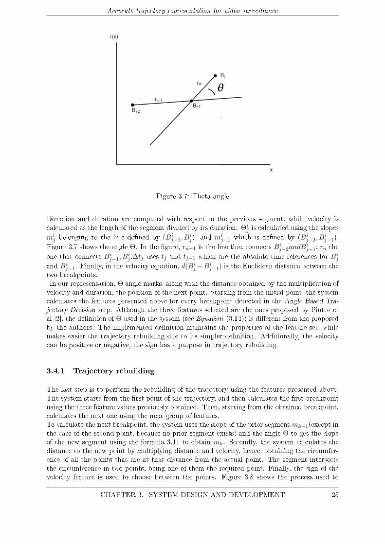
Accurate trajectory representation for video surveillance
Figure 3.7: Theta angle
Direction and duration are computed with respect to the previous segment, while velocity iscalculated as the length of the segment divided by its duration. Θi
j is calculated using the slopesmi
j belonging to the line de�ned by (Bij−1, B
ij); and mi
j−1 which is de�ned by (Bij−2, B
ij−1).
Figure 3.7 shows the angle Θ. In the �gure, rn−1 is the line that connects Bij−2andB
ij−1; rn the
one that connects Bij−1, B
ij .∆tj uses tj and tj−1 which are the absolute time references for Bi
j
and Bij−1. Finally, in the velocity equation, d(Bi
j −Bij−1) is the Euclidean distance between the
two breakpoints.In our representation, Θ angle marks, along with the distance obtained by the multiplication ofvelocity and duration, the position of the next point. Starting from the initial point, the systemcalculates the features presented above for every breakpoint detected in the Angle Based Tra-
jectory Division step. Although the three features selected are the ones proposed by Piotto etal [2], the de�nition of Θ used in the system (see Equation (3.14)) is di�erent from the proposedby the authors. The implemented de�nition maintains the properties of the feature set, whilemakes easier the trajectory rebuilding due to its simpler de�nition. Additionally, the velocitycan be positive or negative, the sign has a purpose in trajectory rebuilding.
3.4.1 Trajectory rebuilding
The last step is to perform the rebuilding of the trajectory using the features presented above.The system starts from the �rst point of the trajectory, and then calculates the �rst breakpointusing the three feature values previously obtained. Then, starting from the obtained breakpoint,calculates the next one using the next group of features.To calculate the next breakpoint, the system uses the slope of the prior segment mk−1(except inthe case of the second point, because no prior segment exists) and the angle Θ to get the slopeof the new segment using the formula 3.11 to obtain mk. Secondly, the system calculates thedistance to the new point by multiplying distance and velocity, hence, obtaining the circumfer-ence of all the points that are at that distance from the actual point. The segment intersectsthe circumference in two points, being one of them the required point. Finally, the sign of thevelocity feature is used to choose between the points. Figure 3.8 shows the process used to
CHAPTER 3. SYSTEM DESIGN AND DEVELOPMENT 25
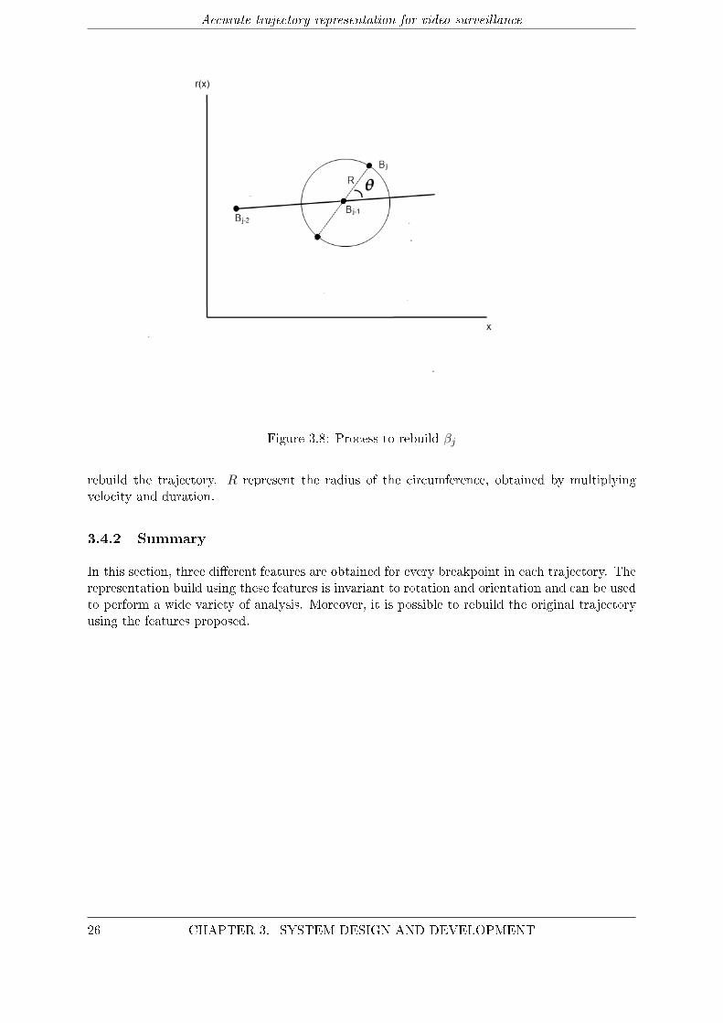
Accurate trajectory representation for video surveillance
Figure 3.8: Process to rebuild βj
rebuild the trajectory. R represent the radius of the circumference, obtained by multiplyingvelocity and duration.
3.4.2 Summary
In this section, three di�erent features are obtained for every breakpoint in each trajectory. Therepresentation build using these features is invariant to rotation and orientation and can be usedto perform a wide variety of analysis. Moreover, it is possible to rebuild the original trajectoryusing the features proposed.
26 CHAPTER 3. SYSTEM DESIGN AND DEVELOPMENT
4Experiments and Results
The objective of this chapter is to present the experiments done to adjust and test the developedsystem. Moreover, the chapter introduces the databases used to evaluate the stages explainedin the previous chapter. The conclusions extracted from the results of the run experimentsare commented in chapter 5. There is an evaluation point for each stage described in chapter3. Additionally a �nal evaluation is included to test the performance of the system used todiscriminate between cars and pedestrians. The chapter is divided as follows:
1. Dataset: brief introduction to the datasets used to evaluate the system. The groundtruth used in the experiments is also presented.
2. Preprocessing module: description of the experiments designed to check the e�ective-ness of each stage of the preprocessing module.
3. Segmentation module: presents the experiment run to set the thresholds related tothe detection of breakpoints. Moreover, the e�cacy of the �ltering stage decreasing thenumber of breakpoints necessary to represent the trajectory is also evaluated.
4. Trajectory features: tests the capacity of the implemented features to represent theoriginal trajectory from which they were extracted. The accuracy in the reconstruction ofthe original trajectory is also checked.
5. Trajectory representation: the tests consist in evaluate the performance of the pro-posed system for object recognition.
6. Real-time performance: test the time performance of the system to evaluate the pos-sibility of working in real-time applications.
4.1 Dataset
In order to consider several scenarios, the system has been tested with surveillance videos fromtwo di�erent datasets. The videos included, present a variety of situations and conditions in-cluding indoors/outdoors scenarios and parked/road environments.
27
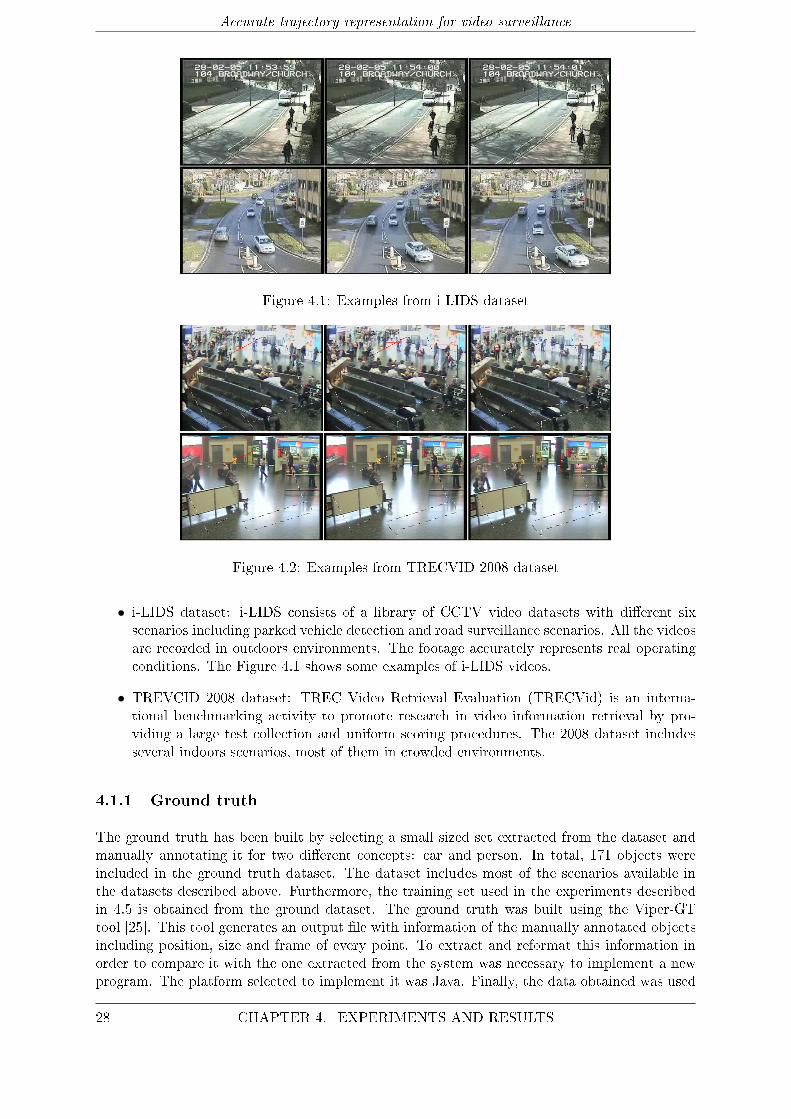
Accurate trajectory representation for video surveillance
Figure 4.1: Examples from i-LIDS dataset
Figure 4.2: Examples from TRECVID 2008 dataset
• i-LIDS dataset: i-LIDS consists of a library of CCTV video datasets with di�erent sixscenarios including parked vehicle detection and road surveillance scenarios. All the videosare recorded in outdoors environments. The footage accurately represents real operatingconditions. The Figure 4.1 shows some examples of i-LIDS videos.
• TREVCID 2008 dataset: TREC Video Retrieval Evaluation (TRECVid) is an interna-tional benchmarking activity to promote research in video information retrieval by pro-viding a large test collection and uniform scoring procedures. The 2008 dataset includesseveral indoors scenarios, most of them in crowded environments.
4.1.1 Ground truth
The ground truth has been built by selecting a small sized set extracted from the dataset andmanually annotating it for two di�erent concepts: car and person. In total, 171 objects wereincluded in the ground truth dataset. The dataset includes most of the scenarios available inthe datasets described above. Furthermore, the training set used in the experiments describedin 4.5 is obtained from the ground dataset. The ground truth was built using the Viper-GTtool [25]. This tool generates an output �le with information of the manually annotated objectsincluding position, size and frame of every point. To extract and reformat this information inorder to compare it with the one extracted from the system was necessary to implement a newprogram. The platform selected to implement it was Java. Finally, the data obtained was used
28 CHAPTER 4. EXPERIMENTS AND RESULTS
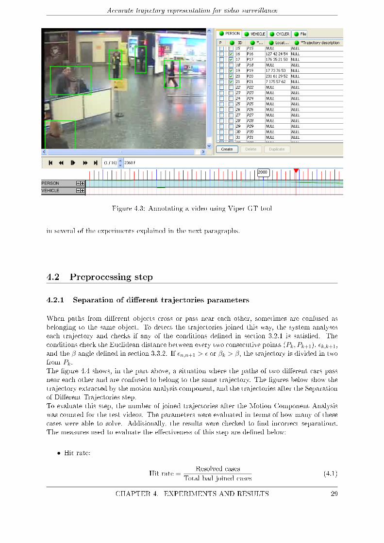
Accurate trajectory representation for video surveillance
Figure 4.3: Annotating a video using Viper-GT tool
in several of the experiments explained in the next paragraphs.
4.2 Preprocessing step
4.2.1 Separation of di�erent trajectories parameters
When paths from di�erent objects cross or pass near each other, sometimes are confused asbelonging to the same object. To detect the trajectories joined this way, the system analyseseach trajectory and checks if any of the conditions de�ned in section 3.2.1 is satis�ed. Theconditions check the Euclidean distance between every two consecutive points (Pk, Pk+1), εk,k+1,and the β angle de�ned in section 3.3.2. If εn,n+1 > ε or βk > β, the trajectory is divided in twofrom Pk.The �gure 4.4 shows, in the part above, a situation where the paths of two di�erent cars passnear each other and are confused to belong to the same trajectory. The �gures below show thetrajectory extracted by the motion analysis component, and the trajectories after the Separationof Di�erent Trajectories step.To evaluate this step, the number of joined trajectories after the Motion Component Analysiswas counted for the test videos. The parameters were evaluated in terms of how many of thesecases were able to solve. Additionally, the results were checked to �nd incorrect separations.The measures used to evaluate the e�ectiveness of this step are de�ned below:
• Hit rate:
Hit rate =Resolved cases
Total bad joined cases(4.1)
CHAPTER 4. EXPERIMENTS AND RESULTS 29
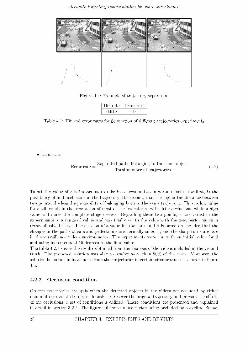
Accurate trajectory representation for video surveillance
Figure 4.4: Example of trajectory separation
Hit rate Error rate0.916 0
Table 4.1: Hit and error rates for Separation of di�erent trajectories experiments
• Error rate:
Error rate =Separated paths belonging to the same object
Total number of trajectories(4.2)
To set the value of ε is important to take into account two important facts: the �rst, is thepossibility of �nd occlusions in the trajectory; the second, that the higher the distance betweentwo points, the less the probability of belonging both to the same trajectory. Thus, a low valuefor ε will result in the separation of most of the trajectories with little occlusions, while a highvalue will make the complete stage useless. Regarding these two points, ε was varied in theexperiments to a range of values and was �nally set to the value with the best performance interms of solved cases. The election of a value for the threshold β is based on the idea that thechanges in the paths of cars and pedestrians are normally smooth, and the sharp turns are rarein the surveillance videos environments. The experiments were run with an initial value for βand using increments of 10 degrees to the �nal value.The table 4.2.1 shows the results obtained from the analysis of the videos included in the groundtruth. The proposed solution was able to resolve more than 90% of the cases. Moreover, thesolution helps to eliminate noise from the trajectories in certain circumstances as shown in �gure4.5.
4.2.2 Occlusion conditions
Objects trajectories are split when the detected objects in the videos get occluded by eitherinanimate or detected objects. In order to recover the original trajectory and prevent the e�ectsof the occlusions, a set of conditions is de�ned. These conditions are presented and explainedin detail in section 3.2.2. The �gure 4.6 shows a pedestrian being occluded by a cyclist. Below,
30 CHAPTER 4. EXPERIMENTS AND RESULTS
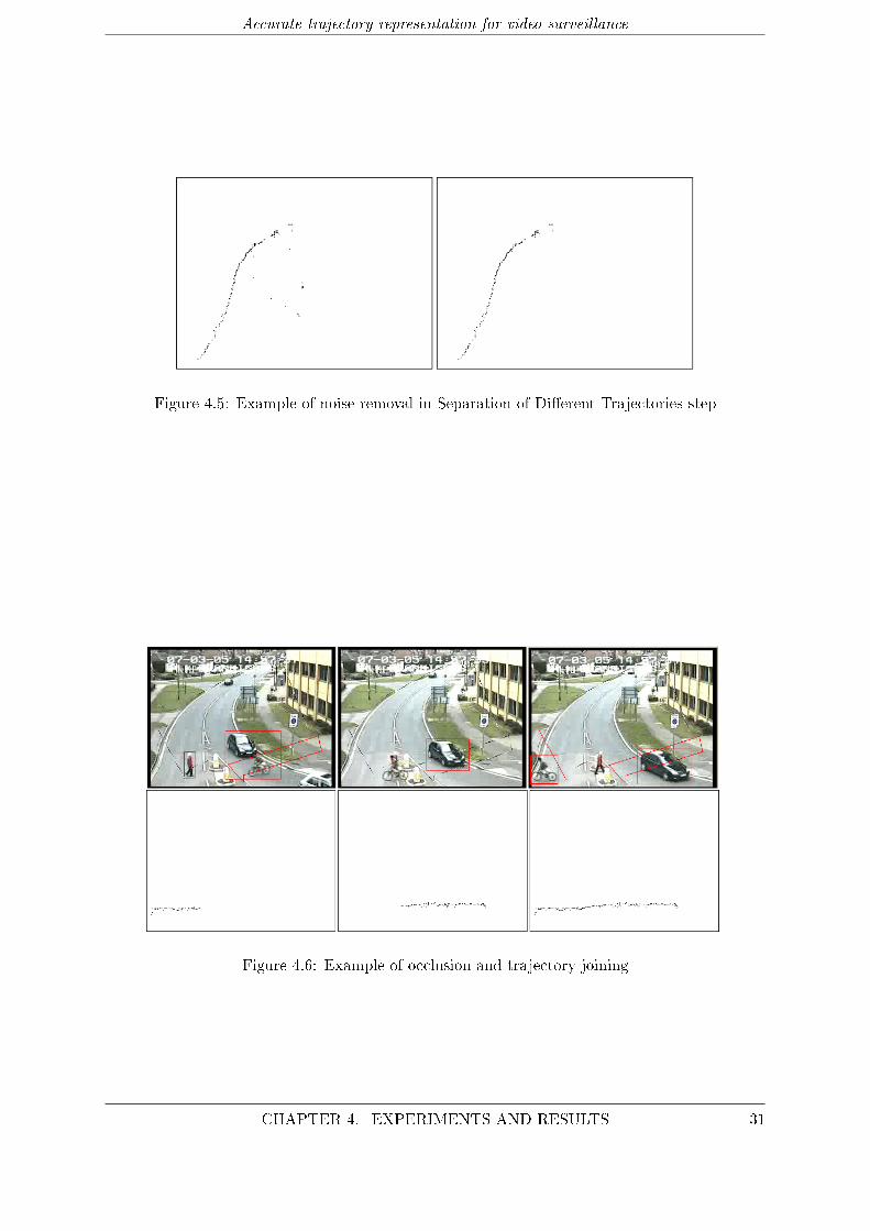
Accurate trajectory representation for video surveillance
Figure 4.5: Example of noise removal in Separation of Di�erent Trajectories step
Figure 4.6: Example of occlusion and trajectory joining
CHAPTER 4. EXPERIMENTS AND RESULTS 31

Accurate trajectory representation for video surveillance
the paths detected by the motion analysis component and the �nal joined path are represented.The measures used in this experiments are similar to the ones used in the previous section.The di�erence is that the occlusions were count directly on the annotations. The e�ects of thevariables values are discussed in the next paragraphs:
• Spatio-temporal proximity: to join two paths, �rst is necessary to check their spatio-temporal proximity. Two thresholds N and F were implemented to check this condition.A small value for N decreases overly the chance to make joints, due to the merge of objectsin the motion analysis component. This happens when an object occults other, and themotion analysis component treat them like a new object for an interval of time δt. If δt isbigger enough, the chance of recover the trajectory by joining the separated paths is verylow. Therefore, a big value ensures to resolve more occlusions,in spite of increasing thechance to make an incorrect joining as well. In the case of F , the reference chosen was amaximum of 1 second between paths.
• Similar direction: this condition is necessary to avoid joining close paths of similar objectsthat move in di�erent directions. To set the value for the threshold α2, several values weretested in the experiments. Finally the value was set trying to minimize the error rate.
• Similar size: the Spatio-temporal proximity condition ensures that the paths being anal-ysed must be close in distance. This means the e�ect of the image depth can not a�ectmuch to the size of the object. Thus, if the two paths belong to the same object, theirsize must be similar. To ensure the paths have a similar average size a maximum sizeincrement threshold is implemented. The size increment measurement ∆S is de�ned informula 5.1:
|S1−S2|S1
< ∆S (5.1)
In the experiments, to �nd an appropriate value for ∆S; examples of the most commonobjects, pedestrians and vehicles, were extracted in positions separated N (see the �rstcondition spatio-temporal proximity). For each sample, a size increment was calculated.Then, the value of ∆S was set using the results shown in table 4.2.2.
Average size increment ∆S
Pedestrians 0.013Vehicles 0.035
Table 4.2: Average ∆S for cars and pedestrians
Hit rate Error rate0.125 0.008
Table 4.3: Occlusion scores
The table 4.2.2 shows the results for occlusion handling based on the analysis of the selectedvideo dataset. The proposed solution is e�ective in only 12.5% of the cases.
32 CHAPTER 4. EXPERIMENTS AND RESULTS

Accurate trajectory representation for video surveillance
4.2.3 False objects removal conditions
In section 3.2.4, the steps to perform the false object removal are explained in detail. Someof the conditions that the objects need to check to be considered proper objects are de�ned asthresholds or variables. The performance measures used in this experiments are again the onesde�ned in Section 4.2.1. In the next paragraphs, the values for these thresholds and variablesare set and justi�ed.
• Minimum stroke: a measurement based in Euclidean distance is used to calculate thestroke. The reason beneath the implementation is to �lter most of the false objects causedby light re�ections, which are frequently static but active. Low values increase the numberof false objects in the system while a bigger value can discard real trajectories as if theywere false.
• Minimum size: the minimum size threshold was established using examples of pedestriansin the farthest distance from the camera as possible. The experiments indicated that isone the less important factors in the task of eliminating false objects.
Hit rate Error rate0.875 0.041
Table 4.4: False object removal scores
The table 4.2.3 shows the results for false object removal. The implemented solution is e�ectivein the 87.5% of the cases.
4.3 Angle-based trajectory division step
4.3.1 Beta and gamma thresholds selection
To adjust the thresholds to the values best �tted to the system, the trajectories were separatedinto three groups: long (>120 points), medium (>60 and <120 points) and short trajectories(<60 points). For each group, 10 trajectories were selected from videos belonging to the testdataset, including both trajectories with big deviations and plain trajectories. In the experi-ments, both the beta and gamma threshold were set to di�erent values. Beta low values resultedin bad approximations to the trajectories, while values over a certain angle do not have signi�-cance e�ects in the number of breakpoints.For each pair of values, two output parameters were analysed: a similarity score between therebuilt trajectory and the preprocessed one, based in Euclidean distance; and the number ofbreakpoints used to represent the trajectory. The objective was to �nd a good relation betweenthe two parameters, leading to a compact and accurate representation. To compare the prepro-cessed trajectory with the one rebuilt from the features, the values between each reconstructedbreakpoint were calculated using linear interpolation. The formula used to calculate the simi-larity score is detailed below:
∑i=ni=1
√(xai − xbi
)2+(yai − ybi
)2n
(4.3)
where (xai , yai ) are the ith coordinates of the original trajectory, (xbi , y
bi ) the ith coordinates of
CHAPTER 4. EXPERIMENTS AND RESULTS 33
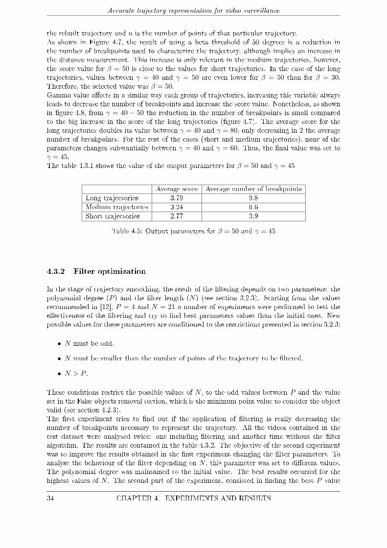
Accurate trajectory representation for video surveillance
the rebuilt trajectory and n is the number of points of that particular trajectory.As shown in Figure 4.7, the result of using a beta threshold of 50 degrees is a reduction inthe number of breakpoints used to characterize the trajectory, although implies an increase inthe distance measurement. This increase is only relevant in the medium trajectories, however,the score value for β = 50 is close to the values for short trajectories. In the case of the longtrajectories, values between γ = 40 and γ = 50 are even lower for β = 50 than for β = 30.Therefore, the selected value was β = 50.Gamma value a�ects in a similar way each group of trajectories, increasing this variable alwaysleads to decrease the number of breakpoints and increase the score value. Nonetheless, as shownin �gure 4.8, from γ = 40 − 50 the reduction in the number of breakpoints is small comparedto the big increase in the score of the long trajectories (�gure 4.7). The average score for thelong trajectories doubles its value between γ = 40 and γ = 80, only decreasing in 2 the averagenumber of breakpoints. For the rest of the cases (short and medium trajectories), none of theparameters changes substantially between γ = 40 and γ = 60. Thus, the �nal value was set toγ = 45.The table 4.3.1 shows the value of the output parameters for β = 50 and γ = 45
Average score Average number of breakpointsLong trajectories 3.79 9.8Medium trajectories 3.24 6.6Short trajectories 2.77 3.9
Table 4.5: Output parameters for β = 50 and γ = 45
4.3.2 Filter optimization
In the stage of trajectory smoothing, the result of the �ltering depends on two parameters: thepolynomial degree (P ) and the �lter length (N) (see section 3.2.3). Starting from the valuesrecommended in [12], P = 4 and N = 21 a number of experiments were performed to test thee�ectiveness of the �ltering and try to �nd best parameters values than the initial ones. Newpossible values for these parameters are conditioned to the restrictions presented in section 3.2.3:
• N must be odd.
• N must be smaller than the number of points of the trajectory to be �ltered.
• N > P .
These conditions restrict the possible values of N , to the odd values between P and the valueset in the False objects removal section, which is the minimum point value to consider the objectvalid (see section 4.2.3).The �rst experiment tries to �nd out if the application of �ltering is really decreasing thenumber of breakpoints necessary to represent the trajectory. All the videos contained in thetest dataset were analysed twice: one including �ltering and another time without the �lteralgorithm. The results are contained in the table 4.3.2. The objective of the second experimentwas to improve the results obtained in the �rst experiment changing the �lter parameters. Toanalyse the behaviour of the �lter depending on N , this parameter was set to di�erent values.The polynomial degree was maintained to the initial value. The best results occurred for thehighest values of N . The second part of the experiment, consisted in �nding the best P value
34 CHAPTER 4. EXPERIMENTS AND RESULTS
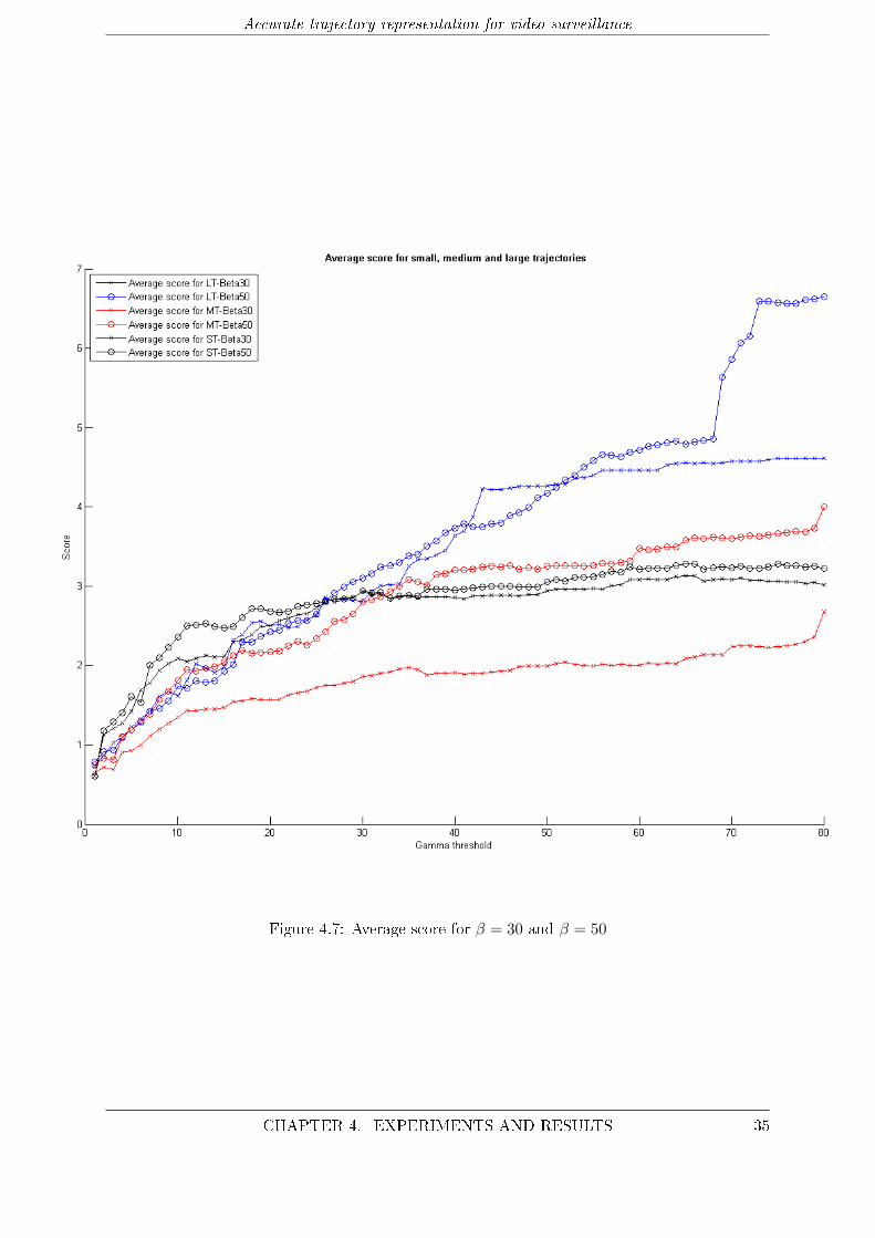
Accurate trajectory representation for video surveillance
Figure 4.7: Average score for β = 30 and β = 50
CHAPTER 4. EXPERIMENTS AND RESULTS 35
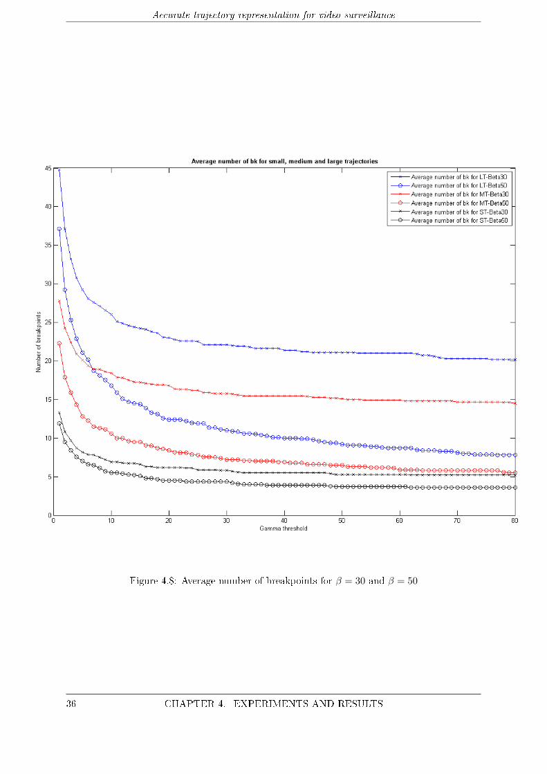
Accurate trajectory representation for video surveillance
Figure 4.8: Average number of breakpoints for β = 30 and β = 50
36 CHAPTER 4. EXPERIMENTS AND RESULTS
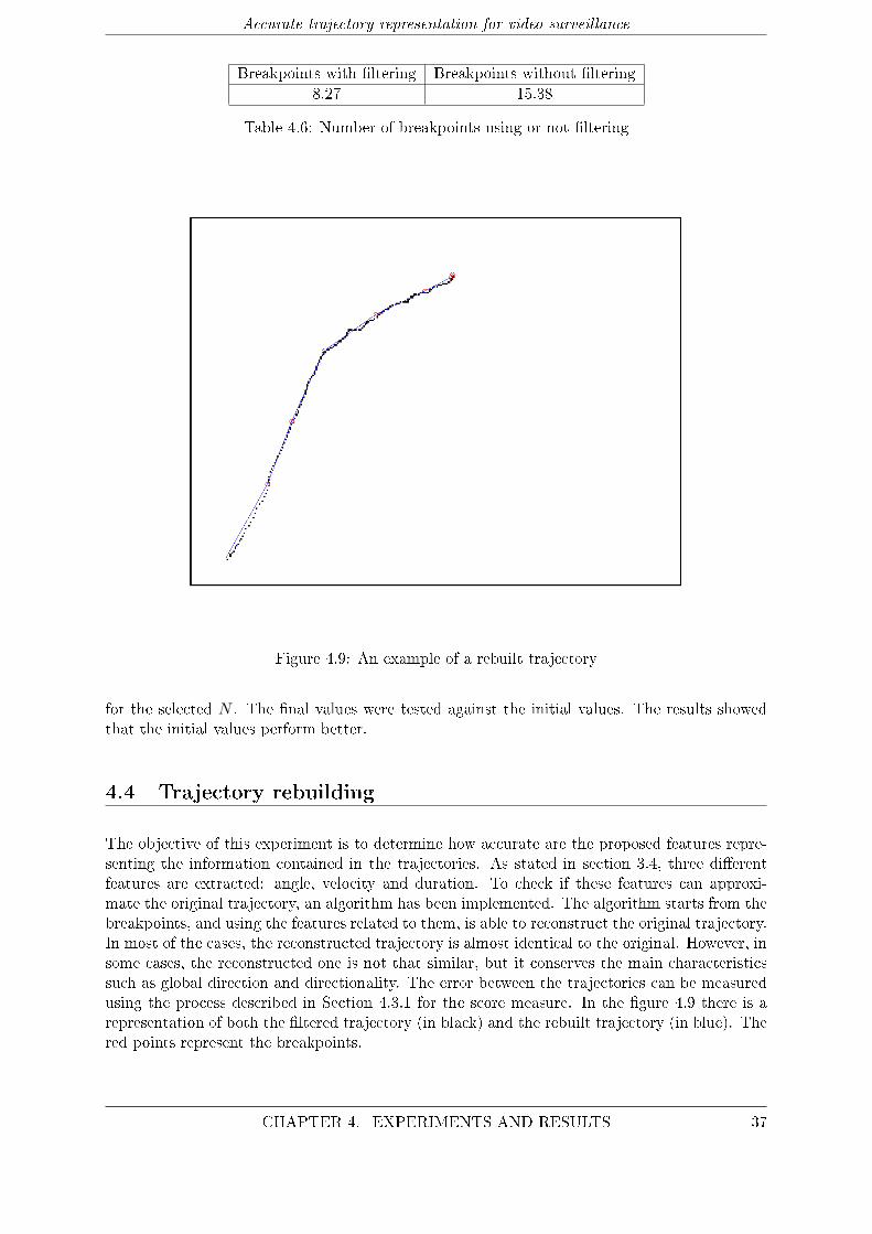
Accurate trajectory representation for video surveillance
Breakpoints with �ltering Breakpoints without �ltering8.27 15.38
Table 4.6: Number of breakpoints using or not �ltering
Figure 4.9: An example of a rebuilt trajectory
for the selected N . The �nal values were tested against the initial values. The results showedthat the initial values perform better.
4.4 Trajectory rebuilding
The objective of this experiment is to determine how accurate are the proposed features repre-senting the information contained in the trajectories. As stated in section 3.4, three di�erentfeatures are extracted: angle, velocity and duration. To check if these features can approxi-mate the original trajectory, an algorithm has been implemented. The algorithm starts from thebreakpoints, and using the features related to them, is able to reconstruct the original trajectory.In most of the cases, the reconstructed trajectory is almost identical to the original. However, insome cases, the reconstructed one is not that similar, but it conserves the main characteristicssuch as global direction and directionality. The error between the trajectories can be measuredusing the process described in Section 4.3.1 for the score measure. In the �gure 4.9 there is arepresentation of both the �ltered trajectory (in black) and the rebuilt trajectory (in blue). Thered points represent the breakpoints.
CHAPTER 4. EXPERIMENTS AND RESULTS 37
Accurate trajectory representation for video surveillance
4.5 Object recognition based on velocity
This experiment pursues to determine if the velocity feature extracted is e�ective to discriminatebetween vehicles and pedestrians. The main reason to select this feature is that is reasonablythink that there will be big di�erences in the velocity of cars and pedestrians even in an urbanenvironments. Using the examples hand-annotated (from videos of i-LIDS dataset) for theground truth, a number of velocity vectors is used to train a system of SVMs [26]. The testdataset is compose of extracted objects from the i-LIDS dataset.The reason for choosing all thetest trajectories from the same dataset is that the velocity is extracted in pixels/second whichmeans that is high dependent on the distance between the camera and the object.In the measurements extracted from the SVM system, the di�erence expected between thevelocity of vehicles and pedestrians was not enough to make a correct classi�cation. The classi�erwas unable to distinguish between the two concepts of object, thus demonstrating the ine�cacyof velocity to perform object recognition.
4.6 Real-time performance
The Motion Analysis Component described in chapter 3 can be used to work in real-time appli-cations with low resolutions. The objective of this experiment is evaluate if the whole system isable to work in real-time. To measure this capacity, the system was run with di�erent videos,estimating the performance time of the implemented parts of the system over the performancetime of the Motion Analysis Component. The results show that the total time of performanceis an 8 − 10% more than the Motion Analysis Component performance time. This result ispromising, despite of not been sustained using a real-time application.
38 CHAPTER 4. EXPERIMENTS AND RESULTS
5Conclusions and future work
5.1 Conclusions
Video surveillance related applications have emerged as a technology covering the increasinglyneed for automated security systems. In these applications, trajectory-based techniques arewidely used to model the behaviour of moving objects in a big variety of scenarios. The ob-jective of this thesis was to design and develop a robust system capable of obtain an accuraterepresentation for these trajectories. Moreover, the implemented system had to be able to re-construct the original trajectory with the less error possible.The results of the experiments probe that the implemented system works good in most of thescenarios used to test the performance. The system is robust against most of the problems en-countered in video surveillance applications, despite of the results for the occlusion case, whichare quite improvable. The path division technique has demonstrate to be e�ective in �nding thepoints which held the information needed to describe the whole trajectory. This fact, togetherwith the good performance of the selected features in the trajectory reconstruction step assuresan accurate reconstruction of the original trajectories. However, the velocity feature demon-strated to be ine�ective for object recognition.The results ensure, therefore, that the implemented system meets the objectives presented inChapter 1. Moreover, the experiments show promising results for real-time performance which isan important requirement for many actual systems. The conclusions for each of the experimentsfor each step are presented below:
• Preprocessing step: the experiments were ran to test the performance of the system againstthe most common challenges in video surveillance systems. The experiments probe thatthe implemented systems deals good in most of the cases, with results near to a 90% ofsolved cases, with the exception of the occlusion handling solution. The geometrical andtemporal conditions implemented to solve occlusions are not e�ective in most of the cases.The addition of a data smoothing step has been proof useful to decrease the number ofbreakpoints necessary to represent the trajectory.
• Angle-based division step: the division of the trajectories into subpaths reduced the num-ber of points necessary to represent the trajectory to less a 10% of the original ones.Also, this division in subpaths makes the system more �exible, allowing to work with thesubpaths or the entire reconstructed trajectories.
39
Accurate trajectory representation for video surveillance
• Trajectory rebuilding: the experiments demonstrate that the reconstructed trajectoriescan approximate the original ones with little error, which at the same time is a proof ofthe good performance of the extracted trajectories in trajectory rebuilding. In addition,the amount of information to represent the trajectories has been reduced, thus meetingthe objective of �nding an accurate and simple representation.
• Object recognition based on velocity: the results for the test of e�ectiveness of the veloc-ity to discriminate between vehicles and pedestrians were poor, thus, an indication thatvelocity has no discrimination power. There was no real di�erence between the velocity ofcars and pedestrians, which can be explained due to the low speed of the vehicles in urbanareas. Additionally, most of the videos were �lmed in places such as pedestrian crossingsand tra�c lights, contributing to slow the average speed of the vehicles.
5.2 Future work
Based on the work done in this thesis, two options are open to continue: enhance the systemand/or extend it developing a high-level application over it. The principal points to enhance inthe system include: robustness against occlusions, extension of the ground truth and increasethe number of features of the system.In the case of occlusion handling, the proposed solutions have not been e�ective. As most of theactual work in occlusion handling is based on robust tracking algorithms, two options must beconsidered: change the current tracking algorithm for other more robust against occlusions or�nd a way to improve the implemented one. Change the algorithm can result in worse resultsdepending on the substitute but the complexity of the current algorithm makes di�cult toimprove the actual implementation.The features used in the system have probed their e�ectiveness, but most of the actual highlevel applications need to extract more information from the videos to perform correctly. Thus,the implementation of new features can facilitate further work on high level concepts.The extension of the ground truth can be an important enhancement. Increasing object examplescan lead to more accurate and complete experiments in the future.The development of a high level application over the system must be studied carefully, becausedepending on the election the system will need to be changed in consequence. Some possibleapplications to extend the presented approach include event detection, crowd analysis or objectidenti�cation.
40 CHAPTER 5. CONCLUSIONS AND FUTURE WORK
Bibliography
[1] Omar Javed and Mubarak Shah. Tracking and object classi�cation for automated surveil-lance. ECCV '02 Proceedings of the 7th European Conference on Computer Vision, 4:343�357, 2002.
[2] Nicola Piotto, Nicola Conci, and Francesco G. B. De Natale. Syntactic matching of trajecto-ries for ambient intelligence applications. IEEE Transactions on Multimedia, 11:1266�1275,2009.
[3] Gill M., Allen A., Jessiman J., Swain D., Hemming M., Kara D, and Little R. Methods inassesing the impact of cctv. Home O�ce Report, 17, 2005.
[4] M. H. Sedky, M. Moniri, and C.C. Chibelushi. Classi�cation of smart video surveillancesystems for commercial applications. IEEE Conference on Advanced Video Signal Based
Surveillance, 1:638�643, 2005.
[5] H. U. Keval and M.A. Sasse. Man or gorilla? performance issues with cctv technologyin security control rooms. 16th World Congress on Ergonomics Conference, International
Ergonomics Asociation, pages 10�14, 2006.
[6] M. Jerian, S. Paolino, F. Cervelli, S. Carrato, A. Mattei, and L. Garofano. A forensic imageprocessing environment for investigation of surveillance video. Forensic Science Interna-
tional, pages 167�170, 2007.
[7] Stefan Muller-Scheneiders, Thomas Jager, Harmut S. Loos, Wolfgang Niem, and RobertBosch. Performance evaluation of a real-time video surveillance system. 2nd Joint IEEE
International Workshop on Visual Surveillance Evaluation of Tracking and Surveillance,1:137�143, 2005.
[8] K. Toyama, J. Krumm, B. Brumitt, and B. Meyers. Wall�ower: Principles and practice ofbackground maintenance. ICCV, page 255, 1999.
[9] Sen-Ching, S. Cheung, and Chandrika Kamath. Robust techniques for background subtrac-tion in urban tra�c video. Visual Communications and Image Processing, 5308:881�892,2004.
[10] A. Prati, I. Mikic, M. Trivedi, and R. Cucchiara. Detecting moving shadows: algorithmsand evaluation. IEEE Transactions on Pat, 25:918�923, 2003.
[11] Alper Yilmaz, Omar Javed, and Mubarak Shah. Object tracking: A survey. ACM Com-
puting Surveys, 38, 2006.
[12] Ivan Ivanov, Frederic Dufaux, Thien M Ha, and Touradj Ebrahimi. Towards generic detec-tion of unusual events in video surveillance. AVSS '09 IEEE Conf. on Advanced Video and
Signal Based Surveillance, 6:61�66, 2009.
[13] F. Fleuret. Fixed point probability �eld for complex occlusion handling. Proceedings of theTenth IEEE International Conference on Computer Vision, 1:694�700, 2005.
41
Accurate trajectory representation for video surveillance
[14] R. Cucchiara, C. Grana, and G. Tardini. Track-based and object-based occlusion for pepletracking re�nement in indoor surveillance. VSSN '04 Proceedings of the ACM 2nd interna-
tional workshop on Video surveillance & sensor network, pages 81�87, 2004.
[15] Hannah M. Dee and Sergio A. Velastin. How close are we to solving the problem of auto-mated visual surveillance systems? Machine vision and applications, 19:329�343, 2008.
[16] C. Stau�er. Estimating tracking sources and sinks. Computer vision and pattern recognition,4:35, 2003.
[17] Brendan T. Morris and Mohan M. Trivedi. A survey of vision-based trajectory learning andanalysis for surveillance. IEEE Transactions on circuits and systems for video technology,18:1114�1127, 2008.
[18] Jianwen Luo, Kui Ying, Ping He, and Jing Bai. Properties of savitzky-golay digital di�er-entiator. Digital Signal Processing, 15:122�136, 2005.
[19] F. Bashir, W. Qu, A. Khokhar, and D. Schonfeld. Hmm-based motion recognition systemusing segmented pca. Proceedings IEEE in Computer Visual Pattern Recognition, 3:1288�1291, 2005.
[20] Fatih Porikli and Tetsuji Haga. Event detection by eigenvector decomposition using objectand frame features. Conference on Computer Vision and Pattern Recognition Workshop,7:114, 2004.
[21] C. Stau�er and W. Eric L. Grimson. Learning patterns of activity using real-time tracking.IEEE Transactions on Pattern Analysis and Machine Intelligence, 22:747�757, 2000.
[22] C. Flanagan. The bresenham line-drawing algorithm, October 1996.http://www.cs.helsinki.�/group/goa/mallinus/lines/bresenh.html.
[23] Gilbert Strang. Linear Algebra and Its Applications. Brooks Cole, 1988.
[24] W.H. Press, S.A. Teukolsky, W.T. Vetterling, and B.P. Flannery. Numerical Recipes in C.Cambridge University Press, 1992.
[25] Language and University of Maryland Media Processing Laboratory. A video processingperformance evaluation tool: Viper-pe. viper-toolkit.sourceforge.net/products/pe/, 2003.
[26] T. Joachims. Svmlight support vector machine, August 2008. svmlight.joachims.org.
42 BIBLIOGRAPHY

APresupuesto
1) Ejecución Material
• Compra de ordenador personal (Software incluido) 2.000 ¤
• Material de o�cina 250 ¤
• Total de ejecución material 2.250 ¤
2) Gastos generales
• sobre Ejecución Material 360 ¤
3) Bene�cio Industrial
• sobre Ejecución Material 135 ¤
4) Honorarios Proyecto
• 1800 horas a 15 ¤/ hora 27000 ¤
5) Material fungible
• Gastos de impresión 200 ¤
• Encuadernación 160 ¤
6) Subtotal del presupuesto
• Subtotal Presupuesto 30.105 ¤
7) I.V.A. aplicable
• 21% Subtotal Presupuesto 6322.05 ¤
8) Total presupuesto
• Total Presupuesto 36427.05 ¤
Madrid, Enero 2013
El Ingeniero Jefe de Proyecto
Fdo.: Gonzalo Varela Bartrina
Ingeniero Superior de Telecomunicación
43

BPliego de condiciones
Pliego de condiciones
Este documento contiene las condiciones legales que guiarán la realización, en este proyecto, deun Accurate trajectory representation for video surveillance. En lo que sigue, se supondrá que elproyecto ha sido encargado por una empresa cliente a una empresa consultora con la �nalidadde realizar dicho sistema. Dicha empresa ha debido desarrollar una línea de investigación conobjeto de elaborar el proyecto. Esta línea de investigación, junto con el posterior desarrollo delos programas está amparada por las condiciones particulares del siguiente pliego.
Supuesto que la utilización industrial de los métodos recogidos en el presente proyecto hasido decidida por parte de la empresa cliente o de otras, la obra a realizar se regulará por lassiguientes:
Condiciones generales.
1. La modalidad de contratación será el concurso. La adjudicación se hará, por tanto, a laproposición más favorable sin atender exclusivamente al valor económico, dependiendo delas mayores garantías ofrecidas. La empresa que somete el proyecto a concurso se reservael derecho a declararlo desierto.
2. El montaje y mecanización completa de los equipos que intervengan será realizado total-mente por la empresa licitadora.
3. En la oferta, se hará constar el precio total por el que se compromete a realizar la obray el tanto por ciento de baja que supone este precio en relación con un importe límite sieste se hubiera �jado.
4. La obra se realizará bajo la dirección técnica de un Ingeniero Superior de Telecomunicación,auxiliado por el número de Ingenieros Técnicos y Programadores que se estime preciso parael desarrollo de la misma.
5. Aparte del Ingeniero Director, el contratista tendrá derecho a contratar al resto del per-sonal, pudiendo ceder esta prerrogativa a favor del Ingeniero Director, quien no estaráobligado a aceptarla.
45
Accurate trajectory representation for video surveillance
6. El contratista tiene derecho a sacar copias a su costa de los planos, pliego de condiciones ypresupuestos. El Ingeniero autor del proyecto autorizará con su �rma las copias solicitadaspor el contratista después de confrontarlas.
7. Se abonará al contratista la obra que realmente ejecute con sujeción al proyecto que sirvióde base para la contratación, a las modi�caciones autorizadas por la superioridad o a lasórdenes que con arreglo a sus facultades le hayan comunicado por escrito al IngenieroDirector de obras siempre que dicha obra se haya ajustado a los preceptos de los pliegosde condiciones, con arreglo a los cuales, se harán las modi�caciones y la valoración de lasdiversas unidades sin que el importe total pueda exceder de los presupuestos aprobados.Por consiguiente, el número de unidades que se consignan en el proyecto o en el presupuesto,no podrá servirle de fundamento para entablar reclamaciones de ninguna clase, salvo enlos casos de rescisión.
8. Tanto en las certi�caciones de obras como en la liquidación �nal, se abonarán los trabajosrealizados por el contratista a los precios de ejecución material que �guran en el presupuestopara cada unidad de la obra.
9. Si excepcionalmente se hubiera ejecutado algún trabajo que no se ajustase a las condicionesde la contrata pero que sin embargo es admisible a juicio del Ingeniero Director de obras, sedará conocimiento a la Dirección, proponiendo a la vez la rebaja de precios que el Ingenieroestime justa y si la Dirección resolviera aceptar la obra, quedará el contratista obligado aconformarse con la rebaja acordada.
10. Cuando se juzgue necesario emplear materiales o ejecutar obras que no �guren en el pre-supuesto de la contrata, se evaluará su importe a los precios asignados a otras obras omateriales análogos si los hubiere y cuando no, se discutirán entre el Ingeniero Directory el contratista, sometiéndolos a la aprobación de la Dirección. Los nuevos precios con-venidos por uno u otro procedimiento, se sujetarán siempre al establecido en el puntoanterior.
11. Cuando el contratista, con autorización del Ingeniero Director de obras, emplee materialesde calidad más elevada o de mayores dimensiones de lo estipulado en el proyecto, o sustituyauna clase de fabricación por otra que tenga asignado mayor precio o ejecute con mayoresdimensiones cualquier otra parte de las obras, o en general, introduzca en ellas cualquiermodi�cación que sea bene�ciosa a juicio del Ingeniero Director de obras, no tendrá derechosin embargo, sino a lo que le correspondería si hubiera realizado la obra con estricta sujecióna lo proyectado y contratado.
12. Las cantidades calculadas para obras accesorias, aunque �guren por partida alzada en elpresupuesto �nal (general), no serán abonadas sino a los precios de la contrata, según lascondiciones de la misma y los proyectos particulares que para ellas se formen, o en sudefecto, por lo que resulte de su medición �nal.
13. El contratista queda obligado a abonar al Ingeniero autor del proyecto y director de obrasasí como a los Ingenieros Técnicos, el importe de sus respectivos honorarios facultativospor formación del proyecto, dirección técnica y administración en su caso, con arreglo alas tarifas y honorarios vigentes.
14. Concluida la ejecución de la obra, será reconocida por el Ingeniero Director que a tal efectodesigne la empresa.
15. La garantía de�nitiva será del 4
16. La forma de pago será por certi�caciones mensuales de la obra ejecutada, de acuerdo conlos precios del presupuesto, deducida la baja si la hubiera.
46 APPENDIX B. PLIEGO DE CONDICIONES
Accurate trajectory representation for video surveillance
17. La fecha de comienzo de las obras será a partir de los 15 días naturales del replanteo o�cialde las mismas y la de�nitiva, al año de haber ejecutado la provisional, procediéndose si noexiste reclamación alguna, a la reclamación de la �anza.
18. Si el contratista al efectuar el replanteo, observase algún error en el proyecto, deberácomunicarlo en el plazo de quince días al Ingeniero Director de obras, pues transcurridoese plazo será responsable de la exactitud del proyecto.
19. El contratista está obligado a designar una persona responsable que se entenderá con elIngeniero Director de obras, o con el delegado que éste designe, para todo relacionadocon ella. Al ser el Ingeniero Director de obras el que interpreta el proyecto, el contratistadeberá consultarle cualquier duda que surja en su realización.
20. Durante la realización de la obra, se girarán visitas de inspección por personal facultativode la empresa cliente, para hacer las comprobaciones que se crean oportunas. Es obligacióndel contratista, la conservación de la obra ya ejecutada hasta la recepción de la misma,por lo que el deterioro parcial o total de ella, aunque sea por agentes atmosféricos u otrascausas, deberá ser reparado o reconstruido por su cuenta.
21. El contratista, deberá realizar la obra en el plazo mencionado a partir de la fecha delcontrato, incurriendo en multa, por retraso de la ejecución siempre que éste no sea debidoa causas de fuerza mayor. A la terminación de la obra, se hará una recepción provisionalprevio reconocimiento y examen por la dirección técnica, el depositario de efectos, el inter-ventor y el jefe de servicio o un representante, estampando su conformidad el contratista.
22. Hecha la recepción provisional, se certi�cará al contratista el resto de la obra, reservándosela administración el importe de los gastos de conservación de la misma hasta su recepciónde�nitiva y la �anza durante el tiempo señalado como plazo de garantía. La recepciónde�nitiva se hará en las mismas condiciones que la provisional, extendiéndose el actacorrespondiente. El Director Técnico propondrá a la Junta Económica la devolución de la�anza al contratista de acuerdo con las condiciones económicas legales establecidas.
23. Las tarifas para la determinación de honorarios, reguladas por orden de la Presidenciadel Gobierno el 19 de Octubre de 1961, se aplicarán sobre el denominado en la actual-idad "Presupuesto de Ejecución de Contrata" y anteriormente llamado "Presupuesto deEjecución Material" que hoy designa otro concepto.
Condiciones particulares.
La empresa consultora, que ha desarrollado el presente proyecto, lo entregará a la empresacliente bajo las condiciones generales ya formuladas, debiendo añadirse las siguientes condicionesparticulares:
1. La propiedad intelectual de los procesos descritos y analizados en el presente trabajo,pertenece por entero a la empresa consultora representada por el Ingeniero Director delProyecto.
2. La empresa consultora se reserva el derecho a la utilización total o parcial de los resultadosde la investigación realizada para desarrollar el siguiente proyecto, bien para su publicacióno bien para su uso en trabajos o proyectos posteriores, para la misma empresa cliente opara otra.
3. Cualquier tipo de reproducción aparte de las reseñadas en las condiciones generales, biensea para uso particular de la empresa cliente, o para cualquier otra aplicación, contarácon autorización expresa y por escrito del Ingeniero Director del Proyecto, que actuará enrepresentación de la empresa consultora.
APPENDIX B. PLIEGO DE CONDICIONES 47
Accurate trajectory representation for video surveillance
4. En la autorización se ha de hacer constar la aplicación a que se destinan sus reproduccionesasí como su cantidad.
5. En todas las reproducciones se indicará su procedencia, explicitando el nombre del proyecto,nombre del Ingeniero Director y de la empresa consultora.
6. Si el proyecto pasa la etapa de desarrollo, cualquier modi�cación que se realice sobre él,deberá ser noti�cada al Ingeniero Director del Proyecto y a criterio de éste, la empresaconsultora decidirá aceptar o no la modi�cación propuesta.
7. Si la modi�cación se acepta, la empresa consultora se hará responsable al mismo nivel queel proyecto inicial del que resulta el añadirla.
8. Si la modi�cación no es aceptada, por el contrario, la empresa consultora declinará todaresponsabilidad que se derive de la aplicación o in�uencia de la misma.
9. Si la empresa cliente decide desarrollar industrialmente uno o varios productos en los queresulte parcial o totalmente aplicable el estudio de este proyecto, deberá comunicarlo a laempresa consultora.
10. La empresa consultora no se responsabiliza de los efectos laterales que se puedan pro-ducir en el momento en que se utilice la herramienta objeto del presente proyecto para larealización de otras aplicaciones.
11. La empresa consultora tendrá prioridad respecto a otras en la elaboración de los proyectosauxiliares que fuese necesario desarrollar para dicha aplicación industrial, siempre que nohaga explícita renuncia a este hecho. En este caso, deberá autorizar expresamente losproyectos presentados por otros.
12. El Ingeniero Director del presente proyecto, será el responsable de la dirección de la apli-cación industrial siempre que la empresa consultora lo estime oportuno. En caso contrario,la persona designada deberá contar con la autorización del mismo, quien delegará en él lasresponsabilidades que ostente.
48 APPENDIX B. PLIEGO DE CONDICIONES
CIntroducción
C.1 Motivación
En los últimos años, se ha incrementado sensiblemente la presencia de sistemas de vídeo vigi-lancia en muchas partes del mundo. El incremento en la demanda de seguridad y la innovacióntecnológica han posibilitado la expansión de estos sistemas. Hoy en día se pueden encontrarcámaras tanto en espacios públicos como aeropuertos o estaciones, como en espacios privadostales como áreas industriales, tiendas o en los hogares. Esto supone que, cada día, se graba unaenorme cantidad de información.La mayoría de los sistemas implementados son monitorizados en su mayor parte por personalde seguridad, lo que conlleva una pérdida de efectividad y una serie de costes que se explicarána continuación. En primer lugar, la enorme cantidad de material �lmado implica que es im-posible mantener un control efectivo sobre el material �lmado sin invertir una cantidad muygrande de dinero en recursos humanos. En segundo lugar, la monitorización no-automática delos contenidos de los vídeos signi�ca que será necesaria una segunda revisión de los mismos enel caso de querer extraer nueva información del vídeo. Ante estos problemas, los sistemas yaplicaciones de vídeo automáticos están surgiendo como una solución para mejorar la calidad ylas oportunidades futuras de los sistemas de vídeo vigilancia.Sin embargo, hay una serie de problemas comunes a todos los sistemas de vídeo vigilancia con losque es necesario tratar. Estos problemas incluyen: cambios de iluminación, presencia de ruidoen la grabación o problemas asociados a la baja calidad de los vídeos �lmados. Adicionalmente,pueden aparecer otros problemas relacionados con el contenido del vídeo en cuestión como oclu-siones u objetos inanimados movidos por el viento que pueden empeorar el rendimiento de lossistemas asociados.Muchas de las aplicaciones propuestas o implementadas en el área de la vídeo vigilancia sebasan en la información extraída a partir de la trayectorias de los objetos que se mueven enlos vídeos analizados. Esta información extraída, de naturaleza espacial y temporal, es luegoutilizada por aplicaciones de alto nivel para realizar tareas como monitorización del trá�co, de-tección de eventos inusuales o discriminación de objetos detectados. Dada la dependencia deestos sistemas a la información contenida en las trayectorias, es importante lograr una extraccióny representación precisa de las mismas. Por tanto, cualquier mejora en la extracción y repre-sentación de las trayectorias es paso hacia delante en la mejora de la calidad y los resultados demuchas aplicaciones en el campo de la vídeo vigilancia.
49
Accurate trajectory representation for video surveillance
C.2 Objetivos
El objetivo de este proyecto es el diseño e implementación de un sistema capaz de extraer yrepresentar de forma precisa las trayectorias de los objetos en movimiento de los vídeos analiza-dos. Además, se pretende que la implementación sea capaz de afrontar los desafíos comunes atodo sistema automático de vídeo vigilancia como son el tratamiento de ruido, oclusiones y otrosproblemas relacionados. Para la consecución de estos objetivos, es necesario completar una seriede objetivos parciales que se muestran a continuación:
• Estudiar en la literatura la viabilidad de las soluciones actuales a los problemas de ruido,oclusión, reducción de la dimensionalidad y otros problemas asociados a los sistemas basa-dos en la extracción de trayectorias.
• Implementar un método para la detección de cambios espaciales y temporales, haciendoposible la fragmentación de la trayectoria en partes con un comportamiento homogéneointernamente, facilitando de esta manera la posterior representación de las trayectorias.
• Encontrar e implementar una serie de características que representen las trayectorias delos objetos detectados, centrándose en la precisión y complejidad de las mismas.
• Evaluar el funcionamiento y comportamiento de cada una de las técnicas implementadas.
• Evaluar el funcionamiento del sistema completo usando bases de datos de vídeo vigilanciaestándar, a régimen de poder dotar de signi�cado a los resultados.
C.3 Estructura del documento
El documento se ha estructurado como se expone a continuación:
• Capítulo segundo: en este capítulo se realiza el estudio y la exposición de los problemas ydesafíos presentes en los sistemas de vídeo vigilancia. Además se exponen las principalestécnicas encontradas en la literatura para el análisis de los objetos en movimiento envídeos, solución de los problemas de oclusión , mejora de la calidad de las trayectorias yrepresentación de éstas últimas.
• Capítulo tercero: en este capítulo se introduce el sistema propuesto, presentando cadaetapa del mismo desde el análisis de movimiento hasta la etapa de evaluación. Los al-goritmos y técnicas son explicados a fondo, detallando las ventajas y desventajas de laimplementación elegida. Adicionalmente, se analizan los problemas y limitaciones halla-dos en su implementación, explicando para cada caso la solución adoptada.
• Capítulo cuarto: en este capítulo se presentan los experimentos llevados a cabo para evaluarel sistema. Las bases de datos elegidas para realizar los experimentos son presentadas alinicio del capítulo.
• Capítulo quinto: las conclusiones extraídas y las posibilidades de trabajo futuro se analizanen este capítulo.
50 APPENDIX C. INTRODUCCIÓN

DConclusiones y trabajo futuro
D.1 Conclusiones
Las aplicaciones y sistemas de vídeo vigilancia han surgido para cubrir la demanda de sistemasde vídeo seguridad automáticos. Entre estas aplicaciones, una importante proporción utilizatécnicas basadas en la extracción de trayectorias para analizar y modelar el comportamiento delos objetos en movimiento en una gran variedad de escenarios. El objetivo �nal de este proyectoera diseñar y desarrollar un sistema robusto capaz de generar una representación precisa de lastrayectorias. Así mismo, el sistema debía ser capaz de reconstruir las trayectorias originales conel menor error posible. Los resultados de los experimentos muestran que el sistema propuestocumple los objetivos en la mayor parte de los escenarios usados para probar su rendimiento. Elsistema es robusto contra casi todos los problemas encontrados en vídeo vigilancia, exceptuandoel caso de las oclusiones, donde el rendimiento es bastante bajo.La técnica de división de trayectorias ha mostrado ser efectiva para encontrar los puntos clave dedonde se puede extraer la información para describir el comportamiento de la trayectoria. Estehecho, junto al éxito de la reconstrucción partiendo de las características extraídas, hace posiblela reconstrucción de las trayectorias originales. Sin embargo, la característica velocidad demostróser completamente ine�caz a la hora de realizar una tarea de reconocimiento de objetos.Los resultados aseguran, por tanto, que el sistema presentado cumple la mayoría de los objetivosmarcados presentados en el capítulo 1. Adicionalmente, los experimentos sobre el tiempo deejecución adelantan un buen rendimiento en sistemas de tiempo real de baja resolución (dondeel Motion Analysis Component puede trabajar en tiempo real).Las conclusiones parciales para cada uno de los experimentos se muestran a continuación:
• Experimentos de la etapa de pre-procesamiento: los experimentos llevados a cabo dieronbuenos resultados contra los problemas más comunes en vídeo vigilancia, con resultadoscercanos al 90% de casos resueltos. La excepción es el caso de la oclusión, donde los resul-tados fueron bastante peores. Las condiciones geométricas y temporales implementadaspara detectar los casos de oclusiones resultados ine�caces en la mayoría de los casos. Porel contrario, el suavizado por �ltrado de las trayectorias demostró ser muy e�caz dismin-uyendo el número de puntos de corte necesarios para representar la trayectoria.
51
Accurate trajectory representation for video surveillance
• Experimentos de la etapa de división de la trayectorias: esta etapa permitió representar(reconstruyendo posteriormente) las trayectorias con tan solo el 10% aproximadamentede los puntos originales. Además, la división de las trayectorias permite trabajar con lastrayectorias reconstruidas o con las partes surgidas de la división.
• Experimentos de la etapa de reconstrucción de las trayectorias: los experimentos muestranque es posible reconstruir las trayectorias originales, manteniendo las características glob-ales y aproximándose bastante al recorrido original. Así mismo, la cantidad de informaciónnecesaria para representar las trayectorias se ha reducido enormemente, cumpliendo los ob-jetivos marcados en el capítulo 1.
• Experimento de reconocimiento de objetos basado en la velocidad: el experimento llevadoa cabo con el �n de determinar si la característica de velocidad era útil para realizar tareasde reconocimiento de objetos arrojó pobres resultados. El clasi�cador no fue capaz dediscriminar entre velocidades de peatones y vehículos. Este hecho puede ser explicado enparte debido a la baja velocidad de los vehículos en entornos urbanos, donde las cámarasfrecuentemente estaban posicionadas cerca de semáforos y pasos de peatones.
D.2 Trabajo futuro
Una vez extraídas las conclusiones �nales, se abren dos opciones: mejorar el sistema y/o ex-tenderlo desarrollando una aplicación de alto nivel sobre el mismo. Los principales puntos amejorar son: la robustez del sistema contra oclusiones, incrementar el número de característicasextraídas y la ampliación de los bancos de pruebas, tanto el ground truth como las bases dedatos utilizadas.En el caso de la oclusión, la solución propuesta ha demostrado ser ine�caz. Dado que la mayoríadel trabajo frente a la oclusión se basa en el diseño de algoritmos de tracking robustos, haydos decisiones posibles. La primera consistiría en cambiar el algoritmo actual por otro másrobusto, mientas que la segunda supone intentar mejorar el algoritmo implementado. Cambiarel algoritmo requeriría probablemente reajustar partes del sistema pero la alta complejidad delalgoritmo actual hace que su mejora pueda resultar una tarea bastante complicada.Las características elegidas para la implementación han probado su utilidad, sobre todo encuanto a representación de trayectorias. Sin embargo, muchas de las aplicaciones de alto nivelrequieren más información de la que estas características pueden proporcionar, por lo que laimplementación de nuevas características puede facilitar mucho el trabajo posterior.La extensión de las bases de datos de pruebas y sobre todo del ground truth conllevaría la obten-ción de unos resultados más precisos y la posibilidad de realizar experimentos más completos.El desarrollo de una aplicación sobre el sistema debe ser meditado con anterioridad, ya quedependiendo de la aplicación elegida habrá que cambiar partes del sistema en consecuencia(reajustar parámetros, implementar nuevas características). Algunos ejemplos de aplicacionesque podrían implementarse sobre el sistema serían detección de eventos inusuales o análisis delcomportamiento de los objetos detectados.
52 APPENDIX D. CONCLUSIONES Y TRABAJO FUTURO


![Untitled Document [arantxa.ii.uam.es]arantxa.ii.uam.es/~cedeps/AM29F010B.pdf · The hardware data protection measures include a low V CC detector automatically inhibits write operations](https://img.pdfslide.net/doc/110x75/5e2e9a8d86a83b734d76307b/untitled-document-cedepsam29f010bpdf-the-hardware-data-protection-measures.jpg)