Embed Size (px)
Citation preview

ACCUWAY MACHINERY CO., LTD.
No. 31, Fenggong Central Rd., Shengang Dist.,
Taichung City 42942, Taiwan (R.O.C.)
TEL: +886-4-2520 9588 FAX: +886-4-2520 9716
E-mail: [email protected]
Website: www.accuway.com.tw
Leader of Accurate Machinery
UT-400/UT-600Super Heavy Duty Turning Center
Series

1 UT-400 Series
The 45 degree slant bed structural design consists of a one piece bed and box way casting with low center of gravity, large swing ciameter, superior rigidity for easy disposal of coolant and chips and longer tool life.
Fine grain wear resisting, shock-absorbing Meehanite cast iron is heat-treated, annealed twice and ground to eliminate internal stress as well as naturally seasoned to attain stability and hardness of HRC 53. This ensures the high rigidity with minimum deformation to meet tough demands from continuous heavy duty and/or step cutting.
Each sliding surface is coated with Turcite-B to obtain long and stable operating life even under rigorous impact loading conditions.
Bed structure is internally reinforced with numerous heavy ribs to reduce deformation from shear or tensile stress.
Rigid Basic Structure
UT-400 Series 2
Rigid B
asic Structure
Rigid B
asic Structure
Spindle design
Twin optimized supports can resist any kind of axial orradial loading generated by high-speed precision turningor low-speed heavy-duty turning.
Inner diameter ofspindle bearings
A2-11
A2-15
A2-20
A2-20
700h6
Φ131 280 180
Φ320 549 397
Φ235 420 300
Φ380
Φ535
603
850 635
457
Precision
Transm
issionand
Position
Con
trol
Power is delivered to the spindle through a two speed geared head allowing stable spindle speed changes as well as powerful torque output.
Helical gears are incorporated in the gearbox to reduce noise, increase contact area, and reduce backlash for even high precision cutting.
Heavy duty servo controlled turret with 2-piece large diameter Hirth-type coupling provides strong clamping, high stiffness, high loading capacity, and precise positioning accuracy. Bi-directional indexing of the 12-station block type turret top plate allows shortest path indexing for reduced non-cut time.
Precision ground ball screw with C3 class hardness ensures high accuracy and durability.
The high-precision tailstock quill encased in a sleeve is fully programmable. The tailstock body is mounted on box ways to ensure maximum rigidity for greater stability when machining long and heavy components between centers, allowing closer tolerances and better surface finishes.
The tailstock taper is MT6 standard, with either a live center or a rotating quill option depending upon requirements.
Hydraulic chuck
Tailstock
Every spindle is assembled, along with headstock and bearings, in a temperature control led environment and with precise fitting jigs. Then it undergoes extensive run-in test to eliminate bear i ng m ismatch a r i s i ng f rom e l e va ted temperatures.
Headstock design, uses symmetrical heat-dissipating ribs, precision-bored and ground to reduce error from heat distortion, maintain circularity and concentricity, thereby ensuringlong-term cutting accuracy.
rough
Powerful Main Spindle Design
Special Turret Design and Precision Motion Control
Pow
erful Main S
pindle Design
Sturdy turret design
3 4 UT-400 Series UT-400 Series
High-precision spindle is supported by large-diameter, taper roller bearings and transmitted by 2-step or 4-step gears
Spindle nose taper Spindle hole diameter (mm)
Outer diameter ofspindle bearings
(mm) (mm)
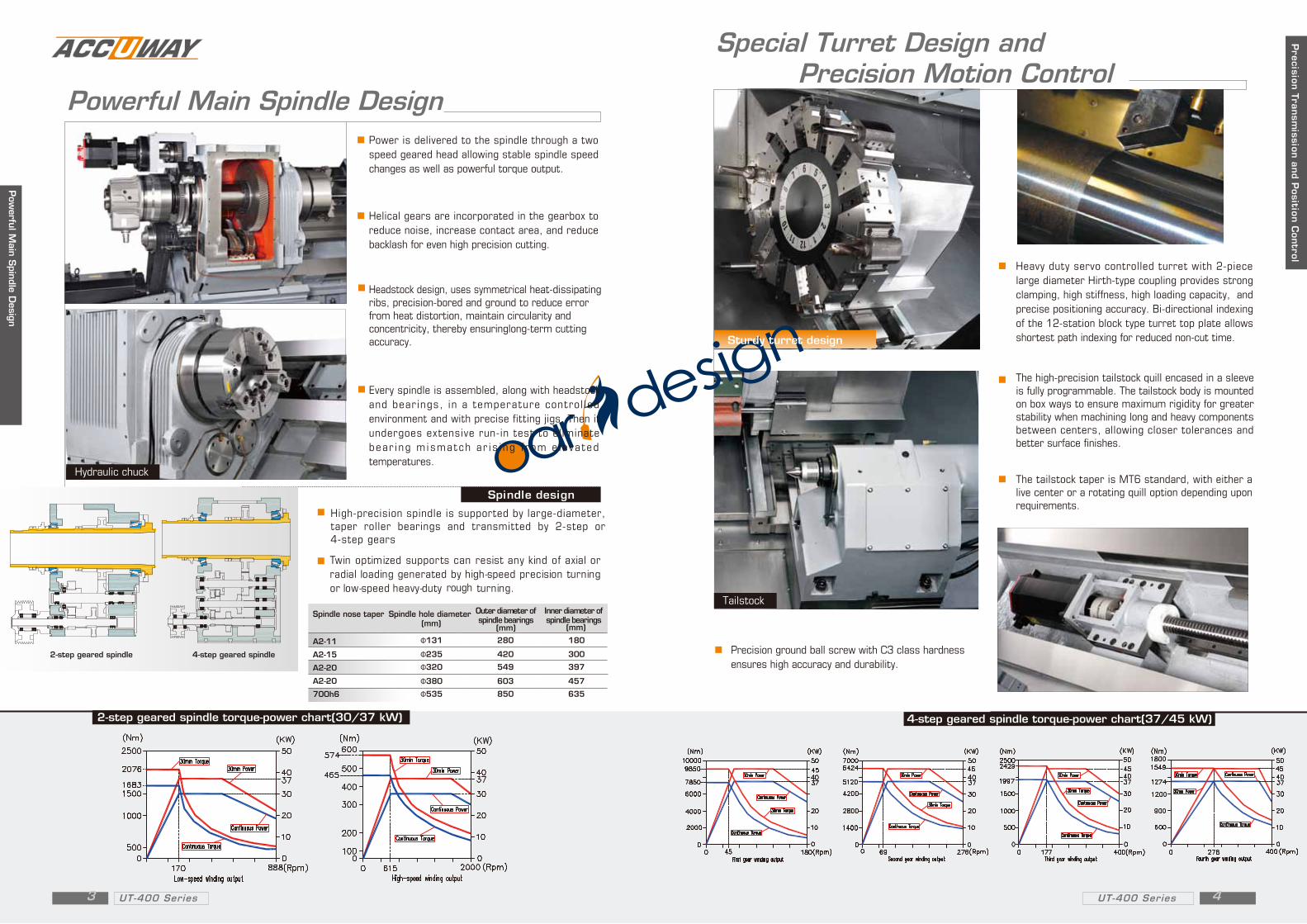
2-step geared spindle torque-power chart(30/37 kW) 4-step geared spindle torque-power chart(37/45 kW)
2-step geared spindle 4-step geared spindle

Steady rest
UT-400 Machine dimensions
UT-600 Machine dimensions
model
A
UT-400/1500
5900(mm)
UT-400/2100
6775(mm)
UT-400/3000
8025(mm)
UT-400/4000
9025(mm)
Heavy Duty Servo Mechanical Power Turret + C-axis index control
New design high rigid 12-station base mount tooling turret is capable of accepting rotary tools at any station, providing flexible machining through various machining operations in just one set-up. Each tool holder is securley tightened by 4 screws, allowing the turret to perform heavy-duty cutting, milling and drilling operations. Turret indexing is non-stop, bi-directional with a fast 3 second next station index time.
T o p r e v e n t l o n g i t u d i n a l def lect ion induced by work p i e c e w e i g h t , h y d r a u l i c controlled automatic steady rest is available as an option to maintain cutting precision for large and long workpiece.
To cope with rigorous heavy cutting demands, the power turret features a special driving method that is the most contemporary design, offering 11 kW of driving power for rotary tools to satisfy versatile heavy cutting process.
Strong Live Tooling for Long, Large Sized Workpieces
Strong Live Tooling for Long, Large S
ize Workpieces
A
MODEL UT-600/1500 UT-600/2100
5900(mm) 6775(mm)
232" 267"
A
MODEL UT-600/3000 UT-600/4000
8025(mm) 9025(mm)
316" 355"
5 UT-400/UT-600 Series UT-400/UT-600 Series 6
Tooling system
& M
ach
ine d
imen
sions
UT-4
00
/U
T60
0

Tool interferen
ce & W
orking ra
nge d
iagra
m
12-station servo turret
facing tool holder
O.D tool clamper
Boring bar tool holder
U-drill tool holde
32x32
32x32
ø20ø25ø32
ø40
facing tool holder
Boring bar tool holder
U-drill tool holde
12-station APT turret
O.D facing tool holder
Axial driven tool holder
Radial driven tool holder
ER 50
ER 50
32x32
32x32
ø20ø25ø32
ø40
Standard 12-Station Servo Turret APT Power Turret
Tool interferen
ce & W
orking ra
nge d
iagra
m
Z travel:1500Z travel:2200Z travel:3100Z travel:4100
168
ø381
135.
7
150
Tailstock travel:1350Tailstock travel:2050Tailstock travel:2950Tailstock travel:3950
ø367.5
ø359.5
ø822ø985ø380.9
ø900
40
355
100
150
5511
5
710 450
735
20
X travel 470
Z travel:1500Z travel:2200Z travel:3100Z travel:4100
70
A2-11
15”
150
Tailstock travel:1350Tailstock travel:2050Tailstock travel:2950Tailstock travel:3950
ø350.44
70
ø366.16
ø397.45
ø900ø3
67.5
845
40
450 20
355
710
X travel 470
ø822
ø920.3
168.
1
7 UT-400/UT-600 Series UT-400/UT-600 Series 8
UT-400
UT-400
UT-600UT-600
Z travel:1500Z travel:2200Z travel:3100Z travel:4100
168
150
Tailstock travel:1350Tailstock travel:2050Tailstock travel:2950Tailstock travel:3950
X-axis travel:380
350 30710
355
40
745
34.4
ø381
ø367.5
ø822ø359.5
ø380.9
ø985 ø700
115
55
150
100
745
70
68.1
ø397.4ø920.3
ø366.2
ø822
ø350.4
ø367
.5
ø700
355
71040
350 30
X travel 380
Tailstock travel:1350Tailstock travel:2050Tailstock travel:2950Tailstock travel:3950
150
15”
A2-11
70 Z travel:1500Z travel:2200Z travel:3100Z travel:4100

mm
mm
mm
mm
degree
ASA
in
mm
rpm
KW
mm
mm
mm
m/min
m/min
positions
mm
mm
kW
rpm
Nm
mm
mm
MT#
m
m
kg
Spindle nose
Spindle hole diameter
CAPACITY
SPINDLE
BED
Guide way
Max cutting diameter
TRAVELS
Spindle speed
"X"axis
Rapid traverse-"X"axis
Spindle bearing inner diameter
Type
FEEDS
TOOL TURRET
Weight (aprox)
Square tool shank size
Rotary tool motor power
Rotary tool speed
Rotary tool torque
Quill taper hole
TAILSTOCK
Quill diameter
Quill travel
Swing over "Z" cover
Max cutting length
Slant angle
"Z"axis
Chuck diameter
Rapid traverse-"Z"axis
Spindle drive (Cont./30min rated)
Swing over "X" cover
Machine Model
Controller
Floor space required
Height
DIMENTIONS
Round tool shank size
Number of tools
mm
mm
mm
mm
degree
ASA
in
mm
rpm
KW
mm
mm
mm
m/min
m/min
positions
mm
mm
kW
rpm
Nm
mm
mm
MT#
m
m
kg
Spindle nose
Spindle hole diameter
CAPACITY
SPINDLE
BED
Guide way
Max cutting diameter
TRAVELS
Spindle speed
"X"axis
Rapid traverse-"X"axis
Spindle bearing inner diameter
Type
FEEDS
TOOL TURRET
Weight (aprox)
Square tool shank size
Rotary tool motor power
Rotary tool speed
Rotary tool torque
Quill taper hole
TAILSTOCK
Quill diameter
Quill travel
Swing over "Z" cover
Max cutting length
Slant angle
"Z"axis
Chuck diameter
Rapid traverse-"Z"axis
Spindle drive (Cont./30min rated)
Swing over "X" cover
Machine Specification Machine SpecificationMachine Model
Controller
Floor space required
Height
DIMENTIONS
15(18) / 20 /24
131/235
45
A2-11/ A2-15/A2-20
Box way
2000/800
30/37+ 2-Speed gearbox
180/300
900
UT-400
2.6
6
150
160
12
32
350+30
50
20
Round tool shank size
Number of tools
Machine S
pecification
Machine S
pecification
7.5/11
3000
47 / 70
-
-
-
FANUC 0i-T FANUC 0i-T
745
700
1300
1500 2200 3100 4100
2000 39002900
24 15 610
6.2x2.8 6.9x2.8 8.9x2.87.9x2.8
15000 16000 2200018000
Servo
- -
-
1300 390029002000
1500 410031002200
24 61015
6.2x2.8 6.9x2.8 7.9x2.8 8.9x2.8
16500 18500 20000 24000
3
1030
950
900
131/235/320/380/530
45
A2-11/ A2-15/A2-20
Box way
2000/800/400/400/250
30/37(37/45)+2-speed gearbox
180/300/396/457/635
15(18) / 20 /24
6
150
160
12
20
32
50
UT-600
450+20
Servo
3000
47/70
7.5/11
-
-
-
Servo-mechanical
9 UT-400/UT-600 Series UT-400/UT-600 Series 10
Servo-mechanical
*Specifications are subject to change without prior notice. *Specifications are subject to change without prior notice.