Embed Size (px)
Citation preview

PRODUCT CATALOG

IndexHydraulic Driven Centrifugal Pumps 2-5
MAX Series Hydraulic Driven Centrifugal Pumps 6-7
PTO Driven Centrifugal Pumps 8-9
Belt Driven Centrifugal Pumps (Counterclockwise) 10-13
Belt Driven Centrifugal Pumps (Clockwise) 14-16
Electric Motor Driven Centrifugal Pumps 16
Gasoline Engine Driven Centrifugal Pumps 17-19
ACE/VALVTEC™ Ball Valves 20
Application Information 21
General Information 22
Pipe & Hose Friction Tables 23
Pump Selection Worksheet 24

1
60 YEARS OF INNOVATIONAND STILL PUMPING
2
Visit www.AcePumps.com for our online catalog orto use the Internet Hydraulic Selection Guide.
HYDRAULIC DRIVEN CENTRIFUGAL PUMPS
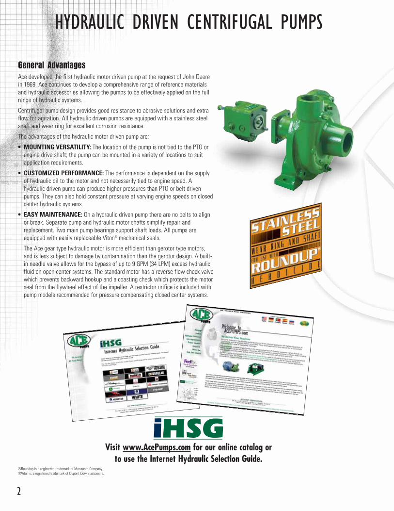
General AdvantagesAce developed the first hydraulic motor driven pump at the request of John Deerein 1969. Ace continues to develop a comprehensive range of reference materialsand hydraulic accessories allowing the pumps to be effectively applied on the fullrange of hydraulic systems.
Centrifugal pump design provides good resistance to abrasive solutions and extraflow for agitation. All hydraulic driven pumps are equipped with a stainless steelshaft and wear ring for excellent corrosion resistance.
The advantages of the hydraulic motor driven pump are:
• MOUNTING VERSATILITY: The location of the pump is not tied to the PTO orengine drive shaft; the pump can be mounted in a variety of locations to suitapplication requirements.
• CUSTOMIZED PERFORMANCE: The performance is dependent on the supplyof hydraulic oil to the motor and not necessarily tied to engine speed. Ahydraulic driven pump can produce higher pressures than PTO or belt drivenpumps. They can also hold constant pressure at varying engine speeds on closedcenter hydraulic systems.
• EASY MAINTENANCE: On a hydraulic driven pump there are no belts to alignor break. Separate pump and hydraulic motor shafts simplify repair andreplacement. Two main pump bearings support shaft loads. All pumps areequipped with easily replaceable Viton® mechanical seals.
The Ace gear type hydraulic motor is more efficient than gerotor type motors,and is less subject to damage by contamination than the gerotor design. A built-in needle valve allows for the bypass of up to 9 GPM (34 LPM) excess hydraulicfluid on open center systems. The standard motor has a reverse flow check valvewhich prevents backward hookup and a coasting check which protects the motorseal from the flywheel effect of the impeller. A restrictor orifice is included withpump models recommended for pressure compensating closed center systems.
®Roundup is a registered trademark of Monsanto Company.®Viton is a registered trademark of Dupont Dow Elastomers.

3
Features• The farm industry standard since 1969.
• The 202 and 203 motors require 2 GPM (7.6 LPM)and 3 GPM (11.4 LPM) hydraulic fluid input.Recommended for engineered systems with limitedoil flow.
• The 204 motor requires 4 GPM (15.1 LPM)maximum hydraulic fluid input.
Recommended for:– Pressure Compensating Closed Center Systems
– Open Center Systems up to 13 GPM (49.2 LPM)using internal needle valve bypass.
• The 210 motor requires 10 GPM (37.9 LPM)maximum hydraulic fluid input.
Recommended for:– Load Sensing Closed Center Systems
– Open Center Systems up to 17 GPM (64.4 LPM)using internal needle valve bypass
• The 310 motor requires 16 GPM (60.6 LPM)maximum hydraulic fluid input.
Recommended for large Open Center Systems up to 24 GPM (90.9 LPM) using internal needlevalve bypass.
Features• Provides higher pressure and greater volume
for applications with large tanks and longer spray booms.
• The 206 motor requires 7 GPM (26.5 LPM)maximum hydraulic fluid input and fits virtually alltractor hydraulic systems.
Recommended for:
– Pressure Compensating Closed Center Systems
– Load Sensing Closed Center Systems
– Open Center Systems up to 16 GPM (60.6 LPM)using internal needle valve bypass
FMC-HYD-202FMC-HYD-203FMC-HYD-204
FMC-HYD-206FMC-HYD-210FMC-HYD-310
11/4"SUCTION
1"
DISCHARGE
Maximum Flow: 92 GPM (350 LPM)Maximum Pressure: 100 PSI (6.9 BAR)
FMC-150-HYD-20611/2"SUCTION
11/4"DISCHARGE
Maximum Flow: 135 GPM (511 LPM)Maximum Pressure: 120 PSI (8.3 BAR)
0
20
40
60
80
100
0
1
2
3
4
5
6
7
0 20 40 60 80 100
0 50 100 150 200 250 300 350
3.8 GPM OIL
3.4 GPM OIL
3.0 GPM OIL
Pre
ssur
e (p
si)
Flow (gpm)
Pressure (bar)
Flow (lpm)
0
20
40
60
80
100
120
0
1
2
3
4
5
6
7
8
0 20 40 60 80 100 120 140
0 100 200 300 400 500
6.2 GPM OIL
5.6 GPM OIL
4.8 GPM OIL
Pre
ssur
e (p
si)
Flow (gpm)
Pressure (bar)
Flow (lpm)
Note: Graph for FMC-HYD-204 model.
GPM3.83.43.0
LPM14.412.911.4
OIL FLOW
GPM6.25.64.8
LPM23.521.218.2
OIL FLOW

4
Features• F model equipped with NPT ports and industry
standard flanged connections.
• FS model constructed of 316 stainless steel with NPT ports and industry standard flanged connections.
• SP model is self-priming making it perfect for loadand spray applications.
• Provides higher pressure and greater volume for applications with large tanks and longer spray booms.
• The 206 motor requires 7 GPM (26.5 LPM)maximum hydraulic fluid input and fits virtually alltractor hydraulic systems.
Recommended for:
– Pressure Compensating Closed Center Systems
– Load Sensing Closed Center Systems
– Open Center Systems up to 16 GPM (60.6 LPM)using internal needle valve bypass
• The 304 motor requires 11 GPM (41.6 LPM)maximum hydraulic fluid input.
Recommended for:
– Pressure Compensating Closed Center Systems
– Load Sensing Closed Center Systems
– Open Center Systems up to 20 GPM (75.7LPM) using internal needle valve bypass
FMC-150F-HYD-206FMC-150FS-HYD-206
Maximum Flow: 145 GPM (549 LPM)155 GPM (587 LPM) for 304
Maximum Pressure: 120 PSI (8.3 BAR)130 PSI (9 BAR) for 304
FMC-150SP-HYD-206
Maximum Flow: 130 GPM (492 LPM)Maximum Pressure: 120 PSI (8.3 BAR)
11/2"220 FLANGE
SUCTION
11/4"200 FLANGE
DISCHARGE
HYDRAULIC DRIVEN CENTRIFUGAL PUMPS
11/2"SUCTION
11/4"DISCHARGE
0
20
40
60
80
100
120
0
1
2
3
4
5
6
7
8
0 20 40 60 80 100 120 140
0 100 200 300 400 500
6.5 GPM OIL
5.8 GPM OIL
5 GPM OIL
Pre
ssur
e (p
si)
Flow (gpm)
Pressure (bar)
Flow (lpm)
0
20
40
60
80
100
120
0
1
2
3
4
5
6
7
8
0 20 40 60 80 100 120
0 80 160 240 320 400 480
7.1 GPM OIL
6.3 GPM OIL
5.5 GPM OIL
Pre
ssur
e (p
si)
Flow (gpm)
Pressure (bar)
Flow (lpm)
GPM7.16.35.5
LPM26.923.820.8
OIL FLOW
GPM6.55.85
LPM24.621.918.9
OIL FLOW
FMC-150F-HYD-304
Note: Graph for FMC-150F-HYD-206 model.

5
Features:• F model equipped with industry standard
flanged connections.
• Ideal for spraying, large tank agitation, liquidtransfer, and spray - transfer combinations
• The 210 motor requires 10 GPM (37.9 LPM)maximum hydraulic fluid input.
Recommended for:
– Pressure Compensating Closed Center Systems
– Load Sensing Closed Center Systems
– Open Center Systems up to 17 GPM (64.4LPM) using internal needle valve bypass
• The 304 motor requires 11 GPM (41.6 LPM)maximum hydraulic fluid input.
Recommended for:
– Pressure Compensating Closed Center Systems
– Load Sensing Closed Center Systems
– Open Center Systems up to 20 GPM (75.7LPM) using internal needle valve bypass
• The 310 motor requires 16 GPM (60.6 LPM)maximum hydraulic fluid input.
Recommended for large Open Center Systemsup to 24 GPM (90.9 LPM) using internal needlevalve bypass.
Maximum Flow: 200 GPM (757 LPM)Maximum Pressure: 120 PSI (8.3 BAR),
80 PSI (5.5 BAR) for 210
FMC-200-HYD-210FMC-200-HYD-304FMC-200-HYD-310
2"
SUCTION
11/2"DISCHARGE
FMC-200F-HYD-304
Maximum Flow: 240 GPM (908 LPM)Maximum Pressure: 120 PSI (8.3 BAR)
300FLANGESUCTION
220FLANGEDISCHARGE
0
20
40
60
80
100
120
0
1
2
3
4
5
6
7
8
0 50 100 150 200 250
0 200 400 600 800
13 GPM OIL
11.5 GPM OIL
10 GPM OIL
Pre
ssur
e (p
si)
Flow (gpm)
Pressure (bar)
Flow (lpm)
0
20
40
60
80
100
120
0
1
2
3
4
5
6
7
8
0 50 100 150 200
0 100 200 300 400 500 600 700
11 GPM OIL
10 GPM OIL
9 GPM OIL
Pre
ssur
e (p
si)
Flow (gpm)
Pressure (bar)
Flow (lpm)
Note: Graph for FMC-200-HYD-304 model.
GPM11109
LPM41.637.934.1
OIL FLOW
GPM1311.510
LPM51.143.537.9
OIL FLOW

MAX SERIES HYDRAULIC DRIVENCENTRIFUGAL PUMPS
General AdvantagesAce’s MAX Series pumps are designed from theground up for today’s demanding applications. Eachmodel is engineered for maximum reliability andperformance. A durable e-coat finish provides extracorrosion resistance on all surfaces inside and out.The 4000 psi high efficiency pressure plated gearmotors provide higher output with less oil flow. The impellers are designed to develop higherpressure at lower shaft speeds. A splined motor topump shaft connection strengthens the power trainwhile allowing for easy repair and maintenance.Oversized bearings round out the list of features for long, trouble free life.
6
Features• Modified impeller design develops higher pressure
at lower RPM.
• F model equipped with NPT ports and industrystandard flanged connections.
• The M16 motor requires 14 GPM (53 LPM)maximum hydraulic fluid input.
Recommended for:
– Pressure Compensating Closed Center Systems
– Load Sensing Closed Center Systems
– Open Center Systems up to 14 GPM (53 LPM)
FMC-650F-HYD
Maximum Flow: 170 GPM (643.5 LPM)Maximum Pressure: 160 PSI (11 BAR)
FMC-650-HYD11/2"SUCTION
11/4"DISCHARGE
Maximum Flow: 140 GPM (530 LPM)Maximum Pressure: 160 PSI (11 BAR)
11/2"220 FLANGE
SUCTION
11/4"200 FLANGE
DISCHARGE
GPM14.313.512.511.29.68
LPM54.151.147.342.436.330.3
OIL FLOW
GPM14.513.612.411.39.88.3
LPM54.951.546.942.837.131.4
OIL FLOW
0
20
40
60
80
100
120
140
160
0
2
4
6
8
10
0 50 100 150
0 80 160 240 320 400 480 560
Pre
ssur
e (p
si)
Flow (gpm)
Pressure (bar)
Flow (lpm)
0
20
40
60
80
100
120
140
160
0
2
4
6
8
10
0 50 100 150 200
0 100 200 300 400 500 600 700
Pre
ssur
e (p
si)
Flow (gpm)
Pressure (bar)
Flow (lpm)
7
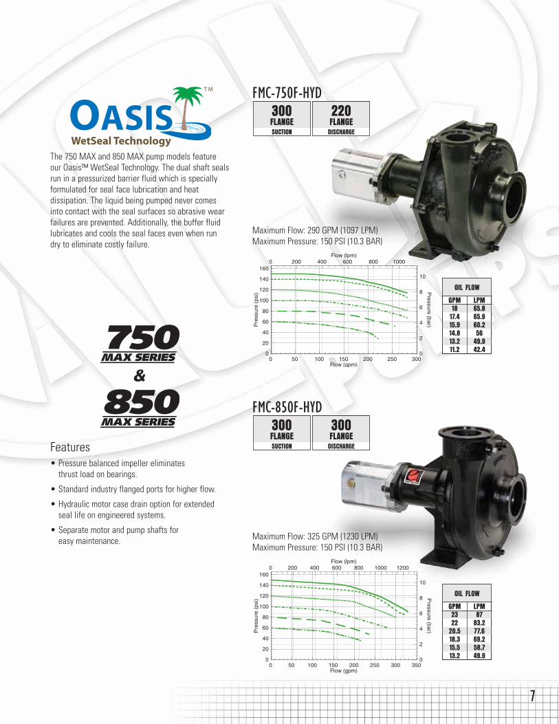
The 750 MAX and 850 MAX pump models feature our Oasis™ WetSeal Technology. The dual shaft sealsrun in a pressurized barrier fluid which is speciallyformulated for seal face lubrication and heatdissipation. The liquid being pumped never comesinto contact with the seal surfaces so abrasive wearfailures are prevented. Additionally, the buffer fluidlubricates and cools the seal faces even when run dry to eliminate costly failure.
Features• Pressure balanced impeller eliminates
thrust load on bearings.
• Standard industry flanged ports for higher flow.
• Hydraulic motor case drain option for extendedseal life on engineered systems.
• Separate motor and pump shafts for easy maintenance.
FMC-750F-HYD
Maximum Flow: 290 GPM (1097 LPM)Maximum Pressure: 150 PSI (10.3 BAR)
FMC-850F-HYD
Maximum Flow: 325 GPM (1230 LPM)Maximum Pressure: 150 PSI (10.3 BAR)
300FLANGESUCTION
220FLANGEDISCHARGE
300FLANGESUCTION
300FLANGEDISCHARGE
GPM2322
20.518.315.513.2
LPM87
83.277.669.258.749.9
OIL FLOW
GPM1817.415.914.813.211.2
LPM65.865.960.256
49.942.4
OIL FLOW
&
0
20
40
60
80
100
120
140
160
0
2
4
6
8
10
0 50 100 150 200 250 300
0 200 400 600 800 1000P
ress
ure
(psi
)
Flow (gpm)
Pressure (bar)
Flow (lpm)
0
20
40
60
80
100
120
140
160
0
2
4
6
8
10
0 50 100 150 200 250 300 350
0 200 400 600 800 1000 1200
Pre
ssur
e (p
si)
Flow (gpm)
Pressure (bar)
Flow (lpm)

8
General AdvantagesPTO belt driven centrifugal pumps were first introduced by Ace in 1964 andenabled the applicator to mount centrifugal pumps directly on 540 RPM and 1000RPM tractor PTO shafts. The simple, yet durable design of the PTOC pump haswithstood the test of time while many attempts at imitation have come and gone.
The key to success of the Ace belt driven pump has been the Spring Loaded Idler.The idler maintains proper belt tension which minimizes the load on the pumpbearings. More importantly, the idler helps absorb the shock of PTO engagementthat can destroy cog belts or gears.
Model PTOC belt driven pumps are easy to operateand maintain. Belts can be replaced in the fieldwith minimum downtime and at little cost.Maintenance features also include sealed ballbearings and a readily replaceable mechanicalseal. The belt guard provides complete coverage ofthe pulleys, shaft and belt. All PTO driven pumpsare equipped with a stainless steel shaft andwear ring for excellent corrosion resistance.
PTO DRIVEN CENTRIFUGAL PUMPS
On trailer mounted units the hitch pin must becentered between the pump and tractor PTO shaftsto minimize vibration transferred to the pumpwhen turning.
PTO Tumble Rod Mounting
SPRINGLOADED
IDLER
L1 = L2H1 = H2
PTOC-600PTOC-1000
11/4"SUCTION
1"
DISCHARGE
Features• Maximum Flow: 65 GPM (246 LPM)
• Maximum Pressure: 80 PSI (5.5 BAR)
• The original belt drive standard since 1964
• Time tested and field proven design
• Widespread parts and service availability
• Most Economical belt drive
PTOC-600 PTOC-1000
®Roundup is a registered trademark of Monsanto Company.
0
20
40
60
80
0
1
2
3
4
5
6
0 10 20 30 40 50 60 70
0 50 100 150 200 250
600 RPM540 RPM500 RPM450 RPM
Pre
ssur
e (p
si)
Flow (gpm)
Pressure (bar)
Flow (lpm)
0
20
40
60
80
0
1
2
3
4
5
6
0 10 20 30 40 50 60 70
0 50 100 150 200 250
1000 RPM900 RPM800 RPM700 RPM
Pre
ssur
e (p
si)
Flow (gpm)
Pressure (bar)
Flow (lpm)

9
PTOC-150-600PTOC-150-1000
11/2"SUCTION
PTO Shaft Options
11/4"DISCHARGE
Features• Maximum Flow: 100 GPM (378 LPM)
• Maximum Pressure: 110 PSI (7.6 BAR)
• The High Performance Pump. 100 PSI(6.9 BAR) at 40 GPM (151 LPM) due toincreased pulley ratio and larger1 1/2" x 1 1/4" construction
• Provides higher pressure and greatervolume for applications with largetanks and long spray booms
• Allows fuel savings by operating atlower engine speeds while maintainingadequate spraying pressures
PTOC-150-600 PTOC-150-1000
1 3/8" (34.9 MM)6 spline shaft for540 RPM models
Instant-attachquick coupler for540 RPM models
21 spline 1 3/8" (34.9 MM)split bore shaft with
locking collar for1000 RPM models
20 spline 1 3/4" (44.5 MM)split bore shaft with
locking collar for1000 RPM models
1" (25.4 MM) stub shaftfor installation on trailer
sprayers driven byPTO tumblerod
-6SP -6SPQC -21SP -20SP -B
0
20
40
60
80
100
120
0
1
2
3
4
5
6
7
8
0 20 40 60 80 100
0 50 100 150 200 250 300 350
600 RPM540 RPM500 RPM450 RPM
Pre
ssur
e (p
si)
Flow (gpm)
Pressure (bar)
Flow (lpm)
0
20
40
60
80
100
120
0
1
2
3
4
5
6
7
8
0 20 40 60 80 100
0 50 100 150 200 250 300 350
1000 RPM900 RPM800 RPM700 RPM
Pre
ssur
e (p
si)
Flow (gpm)
Pressure (bar)
Flow (lpm)

10
BELT DRIVEN CENTRIFUGAL PUMPS
Ace magnetic clutch driven frame mountedcentrifugal pump models are available withcounterclockwise (ccw) rotation and clockwise (cw)rotation. The direction of rotation is determined whenfacing the shaft. Sizes available are 1 1/4" x 1",1 1/2" x 1 1/4", and 2" x 1 1/2".
General AdvantagesFrame Mount AdvantagesAce belt driven pumps are available in a variety of models which can be belt drivenor direct coupled to a power source. The pumps are available in either clockwise orcounterclockwise rotation. The standard bare shaft pumps are designed with akeyway for mounting a drive pulley or coupling.
Magnetic Clutch Driven AdvantagesThe integral magnetic clutch driven centrifugal pump design was first offeredby Ace in 1982. These models enabled the operator to free the PTO shaft andhydraulic system for other uses. The 12 volt DC magnetic clutch is driven by av-belt from the engine drive shaft. The clutch is idle until engaged by an on-offtoggle switch located at the driver’s seat.
Typical Clutch Installation
-MAG-D CLUTCH• 58 ft. lb. (78.6 NM) torque capacity
• Forged machined pulley formaximum strength
• Solid forged rotor to maximize torque
• E-coated for maximum corrosion protection
• High temperature epoxy coil
• Two bearings with high temperature,long life grease
• Single or double belt drive
• 4 3/4" (12.1 CM) pitch diameter
-X FRAME OPTION• 3/4" (1.91 CM) diameter stainless steel shaft,
standard models 5/8" diameter (1.59 CM)
• Larger bearings for extended life
• Available with MAG-D clutch
• 5 1/4" (13.34 cm) mounting bolt spacing
• -X3 frame has 3" (7.62 CM) bolt spacing
FMC-CW-200-X
FMC-CW-200-MAG-D
OFF-ONSWITCH
4 AMPFUSE
MAGNETICCLUTCHDRIVENPUMP
TO 12 VOLTSUPPLY
WATER PUMPSHAFT
ALTERNATOR
ENGINECRANKSHAFTPULLEY

11
The direction of rotation is always determined WHEN FACING THE SHAFT. Thisrule applies for the pump shaft and the drive shaft. Ace Frame Mounted pumps areavailable in both clockwise (CW) and counter-clockwise (CCW) rotation. Ace modelnumbers which include a “CW” have a clockwise rotation; all other models arecounterclockwise rotation.
When direct coupling shafts, always MATCH THE OPPOSITE ROTATION pump withthe shaft. As illustrated, a gasoline engine with CCW rotation will direct couple toa FMC-CW-800 pump with clockwise rotation. When mounting a pump with beltsand pulleys, either pump rotation can be used to match the drive shaft rotation andthe desired direction of the pump.
The rotation of several common power sources are as follows: Gasoline engine andelectric motor shafts rotate in a counterclockwise direction; a tractor PTO shaftrotates in a clockwise direction; the front tractor engine crankshaft rotates in acounterclockwise direction.
Pump Rotation
FMC-CW-800
CCW CW
PTO SHAFT:CLOCKWISE (CW) ROTATION
ELECTRIC MOTOR:COUNTER CLOCKWISE (CCW)
To get the desired performance from an ACE Frame Mounted Pump, the properspeed ratio between the pump and drive source must be established. The followingformula should be helpful:
For example: To drive an FMC-150-MAG pump at 5000 RPM with a drive sourceRPM of 3600 and knowing that the clutch pulley diameter on the pump is 4.75"(12 CM), what should the diameter of the drive pulley be?
The drive pulley diameter, when rounded off should be 6.5" (17 CM).
Pulley Ratio
BELT DEFLECTION
STRAIGHTEDGE
RULER
FMC-150-MAG PUMP A or B “V” BELT
Belt Alignment and TensionProper belt alignment and belt tension will preventpremature bearing failure in the clutch and/or thepump. Use a straight edge held on the faces of thepulleys to check alignment. To provide proper belttension, lay the straight edge on the tops of bothpulleys as shown. Use mild force to deflect the beltas shown. Use a ruler to measure the amount ofdeflection. Proper tension will allow 1/2" (1 CM) ofdeflection for each 12" (30 CM) of distance betweenthe pulleys.
For example: If the distance between the pulleys is3' (90 CM), the deflection should be 1 1/2" (3 CM).
Pump RPMDriveshaft RPM
Drive Pulley DiameterPump Pulley Diameter
=
5000 RPM3600 RPM
Drive Pulley Diameter4.75" (12 CM)
=
ENGLISH1) 5000 x 4.75 = 237502) 23750 ÷ 3600 = 6.59
METRIC1) 5000 x 12 = 600002) 60000 ÷ 3600 = 16.67

12
Features• Counterclockwise Rotation when facing shaft end
• Stainless Steel Shaft and Wear Ring
• Chemical resistant Valox® or optional Cast Iron Impeller
• Standard Viton® Carbon/Ceramic seal or optionalSevere Duty Silicon Carbide Mechanical seal
• SP model is self-priming making it perfect for loadand spray applications.
• F model equipped with NPT ports and industrystandard flanged connections.
BELT DRIVEN CENTRIFUGAL PUMPSCOUNTERCLOCKWISE ROTATION
®Valox is a registered trademark of GE Plastics.®Viton is a registered trademark of Dupont Dow Elastomers.
FMCFMC-MAG-D
11/4"SUCTION
1"
DISCHARGE
Maximum Flow: 70 GPM (265 LPM)Maximum Pressure: 170 PSI (11.7 BAR)Maximum Power: 4.2 HP (3.1 KW)
0
40
80
120
160
0
2
4
6
8
10
12
0 20 40 60 80 100
0 50 100 150 200 250 300 350 400
6000 RPM5000 RPM4400 RPM3800 RPM
Pre
ssur
e (p
si)
Flow (gpm)
Pressure (bar)
Flow (lpm)
FMC-150FMC-150FFMC-150SPFMC-150-MAG-D
11/2"SUCTION
11/4"DISCHARGE
Maximum Flow: 130 GPM (492 LPM)Maximum Pressure: 130 PSI (9 BAR)Maximum Power: 10 HP (7.5 KW)
0
20
40
60
80
100
120
0
2
4
6
8
0 20 40 60 80 100 120
0 100 200 300 400 500
5200 RPM4400 RPM3800 RPM3200 RPM
Pre
ssur
e (p
si)
Flow (gpm)
Pressure (bar)
Flow (lpm)
FMC-150F-MAG-DFMC-150SP-MAG-D

13
Maximum Flow: 140 GPM (530 LPM)Maximum Pressure: 160 PSI (11 BAR)Maximum Power: 22 HP (16.4 KW)
FMC-200FMC-200-MAG-D
2"
SUCTION
11/2"DISCHARGE
Maximum Flow: 200 GPM (757 LPM)Maximum Pressure: 120 PSI (8.3 BAR)Maximum Power: 7.5 HP (5.6 KW)
0
20
40
60
80
100
0
1
2
3
4
5
6
7
0 40 80 120 160
0 100 200 300 400 500 600 700
4600 RPM4000 RPM3600 RPM3200 RPM
Pre
ssur
e (p
si)
Flow (gpm)
Pressure (bar)
Flow (lpm)
0
20
40
60
80
100
120
140
160
0
2
4
6
8
10
0 50 100 150
0 80 160 240 320 400 480 560
4700 RPM4400 RPM4100 RPM3700 RPM
Pre
ssur
e (p
si)
Flow (gpm)
Pressure (bar)
Flow (lpm)
Features• Modified impeller design develops higher pressure
at lower RPM.
• F model equipped with NPT ports and industrystandard flanged connections.
• E-Coat protection for excellent corrosion resistance
Features• Counterclockwise Rotation when facing shaft end
• Stainless Steel Shaft and Wear Ring
• Chemical resistant Valox® or optional Cast Iron Impeller
• Standard Viton® Carbon/Ceramic seal or optionalSevere Duty Silicon Carbide Mechanical seal
11/2"220 FLANGE
SUCTION
11/4"200 FLANGE
DISCHARGE
FMC-650FMC-650F
FMC-650-MAG-DFMC-650F-MAG-D

14
FMC-CWFMC-CW-MAG-D
11/4"SUCTION
1"
DISCHARGE
Maximum Flow: 70 GPM (265 LPM)Maximum Pressure: 170 PSI (11.7 BAR)Maximum Power: 4.2 HP (3.1 KW)
Features• Clockwise Rotation when facing shaft end
• Stainless Steel Shaft and Wear Ring
• Chemical resistant Valox® or optional Cast Iron Impeller
• Standard Viton® Carbon/Ceramic seal or optionalSevere Duty Silicon Carbide Mechanical seal
• MAG-D models equipped with heavy duty12V clutch
• X3 model has 3 1/2" (8.89 CM) spacing onmounting base. All other models have5 1/4" (13.34 CM).
• DX3 model for Spra-Coupe®
Models: 3430, 3440, 3630, 3640, 4440, 4640
®Spra-Coupe is a registered trademark of AGCO Corporation.®Valox is a registered trademark of GE Plastics.®Viton is a registered trademark of Dupont Dow Elastomers.
FMC-CW-150FMC-CW-150-MAG-DFMC-CW-150-MAG-DX3
11/2"SUCTION
11/4"DISCHARGE
Maximum Flow: 80 GPM (303 LPM)Maximum Pressure: 120 PSI (8.3 BAR)Maximum Power: 4.7 HP (3.5 KW)
BELT DRIVEN CENTRIFUGAL PUMPSCLOCKWISE ROTATION
0
20
40
60
80
100
120
140
160
0
2
4
6
8
10
0 20 40 60 80 100
0 50 100 150 200 250 300 350 400
6000 RPM5000 RPM4400 RPM3800 RPM
Pre
ssur
e (p
si)
Flow (gpm)
Pressure (bar)
Flow (lpm)
0
20
40
60
80
100
0
1
2
3
4
5
6
7
0 20 40 60 80 100
0 50 100 150 200 250 300 350 400
5200 RPM4400 RPM3800 RPM3200 RPM
Pre
ssur
e (p
si)
Flow (gpm)
Pressure (bar)
Flow (lpm)

15
Maximum Flow: 140 GPM (530 LPM)Maximum Pressure: 160 PSI (11 BAR)Maximum Power: 22 HP (16.4 KW)
Features• Clockwise Rotation when facing shaft end
• Modified impeller design develops higher pressureat lower RPM.
• E-Coat protection for excellent corrosion resistance
• Standard Viton® Carbon/Ceramic seal or optionalSevere Duty Silicon Carbide Mechanical seal
• MAG-D models equipped with heavy duty12V clutch
0
20
40
60
80
100
120
140
160
0
2
4
6
8
10
0 50 100 150
0 80 160 240 320 400 480 560
4700 RPM4400 RPM4100 RPM3700 RPM
Pre
ssur
e (p
si)
Flow (gpm)
Pressure (bar)
Flow (lpm)
FMC-CW-200FMC-CW-200-MAG-D
2"
SUCTION
11/2"DISCHARGE
Maximum Flow: 200 GPM (757 LPM)Maximum Pressure: 120 PSI (8.3 BAR)Maximum Power: 7.5 HP (5.6 KW)
Features• Clockwise Rotation when facing shaft end
• Stainless Steel Shaft and Wear Ring
• Chemical resistant Valox® or optional Cast Iron Impeller
• Standard Viton® Carbon/Ceramic seal or optionalSevere Duty Silicon Carbide Mechanical seal
• MAG-D models equipped with heavy duty12V clutch
0
20
40
60
80
100
0
0.8
1.6
2.4
3.2
4
4.8
5.6
6.4
0 40 80 120 160
0 80 160 240 320 400 480 560 640
4600 RPM4000 RPM3200 RPM3600 RPM
Pre
ssur
e (p
si)
Flow (gpm)
Pressure (bar)
Flow (lpm)
11/2"220 FLANGE
SUCTION
11/4"200 FLANGE
DISCHARGE
FMC-CW-650FMC-CW-650-MAG-D

16
ACH-5511/4"SUCTION
1"
DISCHARGE
Maximum Flow: 40 GPM (151 LPM)Maximum Pressure: 30 PSI (2.1 BAR)
Features• For most industrial and agricultural blending,
mixing, seed treating and liquid transferapplications.
• Easy replaceable Viton® mechanical seal
• Non-overloading 3/4 HP (.56 KW) 3450 RPM single phase totally enclosed fan cooled electricmotor, for use in all dusty, dirty or weatherexposed locations.
• Optional silicon carbide seal available for abrasivesolutions.
• Chemical resistant Valox® or optional Cast Iron Impeller
ELECTRIC MOTOR DRIVEN CENTRIFUGAL PUMP
A complete line of electric motor driven pumps is available. Contact the factory for details.
ENGLISH UNITSPRESSURE
PSI30252319
FLOWGPM10203040
FLOWGPH600120018002400
METRIC UNITSPRESSURE
BAR2.11.71.61.3
FLOWLPM37.8575.70113.56151.42
FLOWLPH2271454268139085
Data based on 1 foot lift through unrestricted suction hose and fittingswith full 11/4" I.D.
BELT DRIVEN CENTRIFUGAL PUMPSCLOCKWISE ROTATION
FMC-CW-800FMC-CW-800-MAG-D
2"
SUCTION
11/2"DISCHARGE
Maximum Flow: 180 GPM (681 LPM)Maximum Pressure: 170 PSI (11.7 BAR)Maximum Power: 14.2 HP (10.6 KW)
Features• Large diameter impeller provides higher pressure
at slower speeds
• Easily replaceable mechanical seal
• Clockwise Rotation when facing shaft end
• Stainless Steel Shaft
• All iron construction
• Heavy duty double row ball bearings
• Standard Viton® Carbon/Ceramic seal or optionalSevere Duty Silicon Graphite Mechanical seal
0
40
80
120
160
0
2
4
6
8
10
12
0 40 80 120 160
0 100 200 300 400 500 600 700
4200 RPM4000 RPM3800 RPM3600 RPM
Pre
ssur
e (p
si)
Flow (gpm)
Pressure (bar)
Flow (lpm)
®Valox is a registered trademark of GE Plastics.®Viton is a registered trademark of Dupont Dow Elastomers.

17
GASOLINE ENGINE DRIVEN CENTRIFUGAL PUMPS
General AdvantagesAce offers a complete line of Gasoline Engine Driven Centrifugal Pumps. The pumps provide service where power sources are limited orunavailable. The pumps are ideally suited to develop pressure for spray or transfer applications.
The pumps feature a direct coupled design with an easily replaceable mechanical seal and slinger ring between pump and engine to preventliquid from damaging the engine.
The pumps are available complete or less engine (-LE). Complete units come assembled on the specified engine ready to install and run. Lessengine (-LE) units come with all hardware necessary to mount on the specified engine.
Features• Tall Blade Impeller design – higher pressure at
standard engine speeds
• GE-75 Impeller attaches directly to 5/8" (1.59 CM)keyed shaft engine
• GE-85 Impeller attaches directly to 3/4" (1.91 CM)keyed shaft engine
• All Polypropylene corrosion resistant construction
• Available complete or less engine
Maximum Flow: 24 GPM (91 LPM)Maximum Pressure: 65 PSI (4.5 BAR)
GE-85-HONDA
0
10
20
30
40
50
60
70
80
0
1
2
3
4
5
0 5 10 15 20 25
0 20 40 60 80
3950 RPM3600 RPM3000 RPM
Pre
ssur
e (p
si)
Flow (gpm)
Pressure (bar)
Flow (lpm)
Maximum Flow: 25 GPM (95 LPM)Maximum Pressure: 70 PSI (4.8 BAR)
GE-75-HONDA
GE-75GE-85
1"
SUCTION
3/4"DISCHARGE
0
10
20
30
40
50
60
70
0
0.8
1.6
2.4
3.2
4
4.8
0 5 10 15 20 25
0 20 40 60 80
3800 RPM3400 RPM3000 RPM
Pre
ssur
e (p
si)
Flow (gpm)
Pressure (bar)
Flow (lpm)

18
GASOLINE ENGINE DRIVEN CENTRIFUGAL PUMPS
GE-100-A11/4"SUCTION
1"
DISCHARGE
Maximum Flow: 50 GPM (189 LPM)Maximum Pressure: 50 PSI (3.4 BAR)
GE-100-A Features• Impeller attaches directly to 5/8" (1.59 CM) NF
threaded shaft on 3 HP (2.8 KW) to 5.5 HP(4.1 KW) engine
• Stainless steel shaft sleeve with o-ring leak protection
• All iron construction
• Available complete or less engine
GE-650GE-660
11/2"SUCTION
11/4"DISCHARGE
Maximum Flow: 110 GPM (416 LPM)Maximum Pressure: 120 PSI (8.3 BAR)
GE-650 Features• Impeller attaches directly to 5/8" (1.59 CM) NF
threaded shaft on 5.5 HP (4.1 KW) engine
• Stainless steel shaft sleeve with o-ring leak protection
• All iron construction
• Available complete or less engine
GE-660 Features• Impeller attaches directly to 3/4" (1.91 CM) keyed
shaft on 5.5 HP (4.1 KW) engine
• Optional electric start engine
• All iron construction
• Available complete or less engine
0
20
40
60
80
100
120
0
1
2
3
4
5
6
7
8
0 20 40 60 80 100
0 50 100 150 200 250 300 350 400
4200 RPM3800 RPM3400 RPM
Pre
ssur
e (p
si)
Flow (gpm)
Pressure (bar)
Flow (lpm)
0
10
20
30
40
50
0
0.5
1
1.5
2
2.5
3
3.5
0 10 20 30 40 50
0 40 80 120 160
3800 RPM
3600 RPM
3400 RPM
Pre
ssur
e (p
si)
Flow (gpm)
Pressure (bar)
Flow (lpm)

19
GE-800GE-860
2"
SUCTION
11/2"DISCHARGE
Maximum Flow: 140 GPM (530 LPM)Maximum Pressure: 140 PSI (9.7 BAR)
GE-800 Features• Impeller attaches directly to 1" (2.54 CM) - 14 NF
threaded shaft on 8 HP (5.9 KW) to 10 HP(7.5 KW) engine
• Stainless steel shaft sleeve with double o-ring leak protection
• All iron construction
• Available complete or less engine
GE-860 Features• Impeller attaches directly to 1" (2.54 CM) keyed
shaft on 8 HP (5.9 KW) to 10 HP (7.5 KW) engine
• Optional electric start engine
• All iron construction
• Available complete or less engine
GE-160021/2"SUCTION
2"
DISCHARGE
Maximum Flow: 280 GPM (1060 LPM)Maximum Pressure: 120 PSI (8.3 BAR)
GE-1600 Features• Impeller attaches directly to 1" (2.54 CM) - 14 NF
threaded shaft on 16 HP (12 KW) to 20 HP(15 KW) engine
• Standard 16 HP (12 KW) electric start engine
• Stainless steel shaft sleeve with double o-ring leak protection
• All iron construction
• Available complete or less engine
0
50
100
150
0
2
4
6
8
10
0 50 100 150
0 80 160 240 320 400 480 560
3800 RPM3400 RPM3000 RPM
Pre
ssur
e (p
si)
Flow (gpm)
Pressure (bar)
Flow (lpm)
0
20
40
60
80
100
120
140
0
2
4
6
8
0 50 100 150 200 250 300
0 200 400 600 800 1000
3200 RPM3400 RPM3550 RPM
Pre
ssur
e (p
si)
Flow (gpm)
Pressure (bar)
Flow (lpm)

20
ACE/VALVTEC™ BALL VALVES
1. L.H. with flow 2. R.H. with flow 3. L.H. cross flow 4. R.H. cross flow
General AdvantagesACE/VALVTEC™ ball valves are the premium valvesfor critical uses. The valves are available with ratchetor quarter turn handle designs. ACE/VALVTEC™ putsthe durability of metal where performance counts.
Standard Valve Features• Unique diagonally split valve body for easy
cleaning and service
• Ratchet on/off or quarter turn operation
• Rugged all-metal bodies in cast iron, aluminum, or bronze
• Hard chrome plated or stainless steel balls
• Standard and full port models
• Withstand working pressures up to 400 PSI(27.6 BAR)
SERIES 16 STANDARD PORTAvailable with 1/4-turn handle or ratchet handle. An open-closed indicator isprovided with ratchet handle model. Operation of ratchet handle may be cable,chain, cord, or push-pull rods. Available in cast iron, aluminum, or bronze. Choice ofhard chrome plated carbon steel balls or stainless balls. Size range 1/2" to 3" NPT.
SERIES 36 FULL PORTA full flow valve available with 1/4-turn or ratchet handle. Available in cast iron only.Size range 3/4" to 2" NPT.
RATCHET HANDLESRatchet handles are available for Series 16 and Series 36 valves and can besupplied for right or left handed operation and either with flow or crossflow. Anopen-closed indicator is provided with ratchet handle model. Operation of ratchethandle may be cable, chain, cord, or push-pull rods. Please specify when ordering.

21
APPLICATION INFORMATION
SPRAYER PLUMBING SUGGESTIONS
The following are basic guidelines for proper pump mounting: 1) The pump should be mounted below the tanks to allow gravity to naturally fillthe pump with liquid. 2) The volute should be oriented with the discharge port pointing up or across the top of the pump which allows air to riseout of the pump. 3) A petcock valve may be installed in the top most pipe plug hole to allow air to be bled off each time the tanks are filled. 4) Another option would be to install a 1/8'' air bleed line from the top most pipe plug hole to the sprayer tank. This will continually bleed airfrom the pump housing. 5) If the pump must be located above the liquid level, a check valve should be installed to maintain the pump’s prime.
ACE centrifugal pumps are straight centrifugals and must be primed prior to operation. The word “primed” means the pump must be completelyfull of water and any trapped air vented before operation. Following the pump mounting guidelines will insure proper priming of the pump andavoid premature seal failure.
PUMP MOUNTING
GPA = 5940 x GPM (per Nozzle)MPH x W
GPM (per Nozzle) = GPA x MPH x W5940
GPA = Gallons Per AcreGPM = Gallons Per MinuteMPH = Miles Per HourW = Nozzle spacing (in inches) for
broadcast spraying= Spray width (in inches) for single nozzles,
band spraying, or boomless spraying= Row spacing (in inches) divided by the
number of nozzles per row for directed spraying.
USEFUL FORMULASThe primary goal when plumbing a sprayer pump is toroute liquid from the pump to the spray boom withminimum restriction. Minimizing restrictions is necessaryfor achieving the pump’s maximum rated capacity. 1) Hoses should be the same size as the pump’s suctionand discharge ports. 2) Install a pressure gauge and valveon the discharge side of the pump for the purpose ofmeasuring the SHUT-OFF pressure. 3) A minimum numberof elbows, fittings, and valves should be used to reducepressure losses. 4) Plumb a straight section of hoseleading into the suction port equal to 10 times the hoseinside diameter. (i.e. 11/2" hose = 15" of straight hose) 5) Avoid locating electronic spray control valves betweenthe pump and boom. Following these guidelines isnecessary for delivering the highestpressures to the boom.
Anti-Vortex Tank Fitting
Jet Agitator
AgitationPressure Gauge
Pressure Gauge
Line Strainer
Shut-off Valve
Control Valve
Boom Valves
Pressure Spike Valve”Suggested for MAX Series”
Flowmeter
Agitation Valve
Tank Valve
AA = 10 x hose diameter

22
GENERAL INFORMATION
WHP = Ft. Head x GPM
3960
BHP = WHP or BHP =EFF
EFF = WHP x 100BHP
WHP = Water Horsepower
BHP = Brake Horsepower
EFF = Pump Efficiency
To determine the approximate horsepower required for an ACE
centrifugal pump at a given flow and pressure:
HP = GPM x PSI
1714 x .5
To determine the speed at which a liquid is traveling:
Velocity (ft/sec) = .408 x GPM
(pipe diameter)2
To determine the heat generated from by-passed hydraulic oil:
BTU Per Hour = GPM x PSI x 1.48
12,000 BTU/HR = 1 Ton Refrigeration
Feet Head = PSI (water) x 2.31
specific gravity
PSI (pounds per square inch) = Feet Head x .433
Weight of one U.S. Gallon of water = 8.34 pounds
One cubic foot (cu. ft.) of water contains 7.48 gallons
Specific gravity of water (sp. gr.) = 1.0
Water weighs 8.34 lbs./gallon and has a specific gravity of 1. Since specific gravity is a ratio of the weight of a liquid compared to theweight of water, the specific gravity of a liquid such as 28% nitrogen fertilizer, which weighs 10.65 lbs./gallon would be figured thus:
10.65 lbs./gallon = 1.28 specific gravity8.34 lbs./gallon
All pump capacities (GPM) in this catalog are based on water. Whenpumping fluids that are heavier than water, pump capacity will be lessthan stated on each pump performance table. To compensate for pumping heavy liquids, multiply the required pump capacity in GPM timesthe appropriate conversion factor from the above chart.
EXAMPLE: Required pump capacity is 50 GPM of 28% nitrogen fertilizer.
50 x 1.13 = 56.5 GPM
Then select a pump from the preceding pages that will deliver 56.5 GPMat the desired pressure.
Multiply By To ObtainLENGTH inches 25.40 millimeters (mm)
inches 2.540 centimeters (cm)feet 0.3048 meters (m)miles 1.609 kilometers (km)
AREA acres 4046.7 square meters (m2)acres 0.4047 hectares (ha)hectares 2.471 acres
VOLUME gallons 3.785 cubic decimeters (dm3)gallons 3.785 liters (L)gallons 231 cubic inches (in3)Imperial gallons 4.546 liters (L)Imperial gallons 1.201 U.S. gallonsU.S. gallons .833 Imperial gallonsliter 0.264 gallonpounds water 0.119 gallon
FLOW RATE gallons/hour (gph) 3.785 liters/hour (L/h)gallons/minute (gpm) 3.785 liters/minute (L/m)
APPL. RATE gallons/acre (gpa) 9.353 liters/hectare (L/ha)
PRESSURE pounds persquare inch (psi) 6.895 kilopascals (kPa)PSI 2.31 ft. (head) of waterft. (head) of water 0.433 PSIinches mercury (in Hg) 0.491 PSIbar 14.5 PSIkilopascal (KPA) 0.145 PSI
SPEED miles/hour (mph) 1.609 kilometers/hour (km/h)kilometers/hour (km/h) 0.621 miles/hour (mph)
USEFUL FACTORS OR FORMULAS SPECIFIC GRAVITY
CONVERSION FACTORS
Ft. Head x GPM
3960 x EFF (Pump)
SOLUTION WEIGHT8.0 lbs./gal.8.34 lbs./gal.9.0 lbs./gal.10.0 lbs./gal.10.65 lbs./gal.11.0 lbs./gal.
SPECIFIC GRAVITY.961.01.081.21.281.32
CONVERSION FACTOR.981.01.041.11.131.15

23
PIPE & HOSE FRICTION TABLES
PRESSURE DROP IN PSI FOR VARIOUS PIPE SIZES (10FT. LENGTH)
STD. STD.PIPE ACTUAL GATE GLOBE ELBOW TEESIZE INSIDE VALVE VALVE OR RUN THRUSTD. DIAM. 45° RUN OF OF TEE SIDEWT. IN. FULL FULL ELBOW STD. REDUCED OUTLET
OPEN OPEN TEE 1/2
1/8 .269 .15 8 .35 .40 .75 1.4
1/4 .364 .20 11 .50 .65 1.1 2.2
1/2 .622 .35 18.6 .78 1.1 1.7 3.3
3/4 .824 .44 23.1 .97 1.4 2.1 4.2
1 1.049 .56 29.4 1.2 1.8 2.6 5.3
1-1/4 1.380 .74 38.6 1.6 2.3 3.5 7.0
1-1/2 1.610 .86 45.2 1.9 2.7 4.1 8.1
2 2.067 1.1 58 2.4 3.5 5.2 10.4
2-1/2 2.469 1.3 69 2.9 4.2 6.2 12.4
APPROXIMATE FRICTION LOSS IN PIPE FITTINGSin terms of equivalent feet of straight pipe.
FLOW
IN GPM 1/8" 1/4" 3/8" 1/2" 3/4" 1" 11/4" 11/2"
.2 .2
.3 .4
.4 .6 .16
.5 1.0 .24
.6 1.5 .34
.8 2.5 .60 .13
1.0 3.7 .89 .19 .08
1.5 8.0 1.8 .40 .13
2.0 3.1 .65 .21 .05
2.5 4.7 1.1 .32 .08
3.0 6.3 1.5 .45 .11
3.5 2.0 .60 .14
4.0 2.5 .78 .18 .06
4.5 3.1 .98 .23 .08
5.0 3.8 1.2 .28 .09
6.0 5.2 1.6 .38 .11
8.0 2.8 .63 .20 .06
10.0 4.2 1.0 .30 .08 .04
15.0 2.2 .61 .16 .08
20.0 3.8 1.1 .29 .13
25.0 1.7 .41 .20
30.0 2.4 .59 .27
35.0 .79 .36
40.0 1.0 .48
50.0 .71
1/4" 3/8" 1/2" 5/8" 3/4" 1" 11/4" 11/2"I.D. I.D. I.D. I.D. I.D. I.D. I.D. I.D.
.2 .8
.3 1.5
.4 2.5
.5 4.0 .5
.6 5.0 .8
.8 9.0 1.3
1.0 1.8 .5
2.0 6.0 1.5
3.0 13.0 3.1 1.0
4.0 6.0 1.8
5.0 8.5 2.5 1.0
6.0 12.0 3.7 1.5
8.0 6.5 2.5 .6
10.0 9.5 3.7 1.0
15.0 8.0 2.0 .7
20.0 14.0 3.4 1.2 .4
25.0 5.0 1.8 .6
30.0 6.5 2.5 .9
40.0 12.0 4.4 1.4
50.0 6.0 2.1
60.0 9.0 2.9
70.0 13.0 4.0
FLOW
IN GPM
PRESSURE DROP IN PSI FOR VARIOUS HOSE SIZES25 ft. length with no coupling
NOTE: The above figures are for standard hose in good condition with no couplings.
NOTE: The above figures are for standard pipe of either seamless or welded construction, ingood clean condition. Recommended maximum capacity to keep velocity at approximately 5 ft.per second is shown above heavy lines.

24
PUMP SELECTION WORKSHEET
Fill in the application information:
Application Rate (GPA)Speed (MPH)Nozzle Spacing (inches)
� 5940 =
1. Complete the calculations
Identify the flow required for AGITATION (typically 5% of tank’s capacity):
Determine your highest spraying pressure (PSI). (Add 10-15 PSI for system pressure losses.)
Find the TOTAL PUMP FLOW(GPM) calculated above.
Choose the pump by color code orcatalog performance charts.
Then Add:
2.
3.
25 GPM50 GPM37 GPM
75 GPM
500 Gallon Tank1000 Gallon Tank
750 Gallon Tank
1500 Gallon Tank
4.
Boom Flow (GPM) + = Total Pump Flow (GPM) requiredAgitation
(GPM)
+ =
xx=
x=
PUMP SELECTION
1.
2.
3.
HYDRAULIC PUMPS PTO PUMPS
Visit our web site at www.AcePumps.com to use an automated version of this worksheet.
GPM per Nozzle# of Nozzles Boom Flow (GPM)


ACE PUMP CORPORATION • P.O. Box 13187 • 1650 Channel Ave. • Memphis, TN 38113phone: 800.843.2293 • fax: 901.774.6147 • www.AcePumps.com
ACE Form# PROD CATALOG 2009


![EN SuperBetsy Mobile Pump SystemsDescription SB100-DS SB150-EM SB150-EH DN Suction flange (PN10) [mm] DN Discharge flange (PN10) [mm] DN100, PN10 DN100, PN10 DN150, PN10 DN150, …](https://img.pdfslide.net/doc/110x75/6063becdbc70967b2f2a7a36/en-superbetsy-mobile-pump-systems-description-sb100-ds-sb150-em-sb150-eh-dn-suction.jpg)