Embed Size (px)
Citation preview

ACE Engineering Academy Hyderabad|Delhi|Bhopal|Pune|Bhubaneswar| Lucknow|Patna|Bengaluru|Chennai|Vijayawada|Vizag|Tirupati|Kukatpally |Kolkata
: 2 : Mechanical Engg. _ ESE MAINS
ACE Engineering Academy Hyderabad|Delhi|Bhopal|Pune|Bhubaneswar| Lucknow|Patna|Bengaluru|Chennai|Vijayawada|Vizag|Tirupati|Kukatpally |Kolkata
01(a).
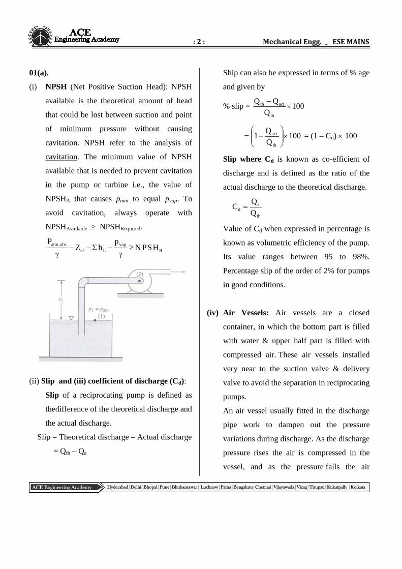
(i) NPSH (Net Positive Suction Head): NPSH
available is the theoretical amount of head
that could be lost between suction and point
of minimum pressure without causing
cavitation. NPSH refer to the analysis of
cavitation. The minimum value of NPSH
available that is needed to prevent cavitation
in the pump or turbine i.e., the value of
NPSHA that causes pmin to equal pvap. To
avoid cavitation, always operate with
NPSHAvailable ≥ NPSHRequired.
Rvap
Lsabs,atm HSPN
phZ
P
(ii) Slip and (iii) coefficient of discharge (Cd):
Slip of a reciprocating pump is defined as
thedifference of the theoretical discharge and
the actual discharge.
Slip = Theoretical discharge – Actual discharge
= Qth – Qa
Ship can also be expressed in terms of % age
and given by
% slip = 100Q
th
actth
100Q
Q1
th
act
= (1 – Cd) 100
Slip where Cd is known as co-efficient of
discharge and is defined as the ratio of the
actual discharge to the theoretical discharge.
th
ad Q
QC
Value of Cd when expressed in percentage is
known as volumetric efficiency of the pump.
Its value ranges between 95 to 98%.
Percentage slip of the order of 2% for pumps
in good conditions.
(iv) Air Vessels: Air vessels are a closed
container, in which the bottom part is filled
with water & upper half part is filled with
compressed air. These air vessels installed
very near to the suction valve & delivery
valve to avoid the separation in reciprocating
pumps.
An air vessel usually fitted in the discharge
pipe work to dampen out the pressure
variations during discharge. As the discharge
pressure rises the air is compressed in the
vessel, and as the pressure falls the air
: 3 : Test – 3
ACE Engineering Academy Hyderabad|Delhi|Bhopal|Pune|Bhubaneswar| Lucknow|Patna|Bengaluru|Chennai|Vijayawada|Vizag|Tirupati|Kukatpally |Kolkata
expands. The peak pressure energy is thus
stored in the air and returned to the system
when pressure falls.
Purposes of Air vessels:
1) To obtain liquid at uniform discharge.
2) Due to air vessel frictional head and
acceleration head decreases and the
work overcoming friction resistance in
suction and delivery pipe considerably
decreases which results in good amount
of work.
3) Reciprocating pump can run at high
speed without flow separation
(v) Specific speed of pumps:Specific speed is
defined as "the speed of an ideal pump
geometrically similar to the actual pump,
which when running at this speed will raise a
unit of volume in a unit of time through a
unit of head".
In metric units
Specific speed 4/3s H
QNN
N = The speed of the pump in revolutions per
minute (rpm)
Q = The flow rate in liters per second (for
either single or double suction impellers)
H = The total dynamic head in meters
In SI units, Q is in cubic meter per second, N
in rpm and H in meters.
01(b).
Sol: Assumption:-
1–D heat conduction Steady state No heat generation
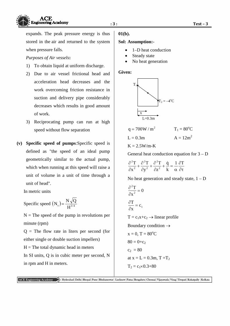
Given:
2m/W700q T1 = 80oC
L = 0.3m A = 12m2
K = 2.5W/m-K
General heat conduction equation for 3 – D
T1
k
q
z
T
y
T
x
T2
2
2
2
2
2
No heat generation and steady state, 1 – D
0x
T2
2
1cx
T
T = c1x+c2 linear profile
Boundary condition
x = 0, T = 80oC
80 = 0+c2
c2 = 80
at x = L = 0.3m, T =T2
T2 = c10.3+80
T1
T2 = –4oC
x
L=0.3m
: 4 : Mechanical Engg. _ ESE MAINS
ACE Engineering Academy Hyderabad|Delhi|Bhopal|Pune|Bhubaneswar| Lucknow|Patna|Bengaluru|Chennai|Vijayawada|Vizag|Tirupati|Kukatpally |Kolkata
According to Fourier law of heat conduction
dx
dTkq [q = heat flux]
L
0
T
T
2
1
kdTqdx
q.L = –k.(T2–T1)
K
L
TTq 21
5.2
3.0
T80700 2
5.2
3.0700T80 2
80–T2 = 84
T2 = –4oC
Comment: This much of temperature
difference, because of very low thermal
conductivity.
: 5 : Test – 3
ACE Engineering Academy Hyderabad|Delhi|Bhopal|Pune|Bhubaneswar| Lucknow|Patna|Bengaluru|Chennai|Vijayawada|Vizag|Tirupati|Kukatpally |Kolkata
oil
water
100C
30C
150C
15C
oil
water
75C
T
150C
15C
Before After
Case (I) Case (II)
01. (c)
Sol:
Assumptions :
Radiation effect is neglected
No fouling
Given,
Thi = 150C ,
Tci = 15C
The = 100C case (i)
Tce = 30C
Energy balance for case (i)
)100150(C.m)1530(C.m 0p0pww
100150C.mC.m15 po0pww
powpww Cm50Cm15 ---- (1)
Cmin =0p0 C.m
pwwmax C.mC
For new case:
75150C.m15TC.m 0p0pww
75C.m15TC.m poopww
From equation (1)
poopww Cm15
50Cm
75150Cm15T15
50C.m po0po0
T – 15 =50
1575
T = 37.5C
Exit temperature of water in new case is 37.5C
LMTD for case (i):
30100
15150n
3010015150Im
=
70
85n
7085
=77.25C
Energy balance
U.AI.Im = m0.Cp0(150–100)
5.3770
15150n
5.377515150IIm
=
5.37
85n
5.3785
=2183.0
5.47
m = 58.46C.
Energy balance
U.AII.IIm = m0.Cpo.(150–75) ----------(2)
: 6 : Mechanical Engg. _ ESE MAINS
ACE Engineering Academy Hyderabad|Delhi|Bhopal|Pune|Bhubaneswar| Lucknow|Patna|Bengaluru|Chennai|Vijayawada|Vizag|Tirupati|Kukatpally |Kolkata
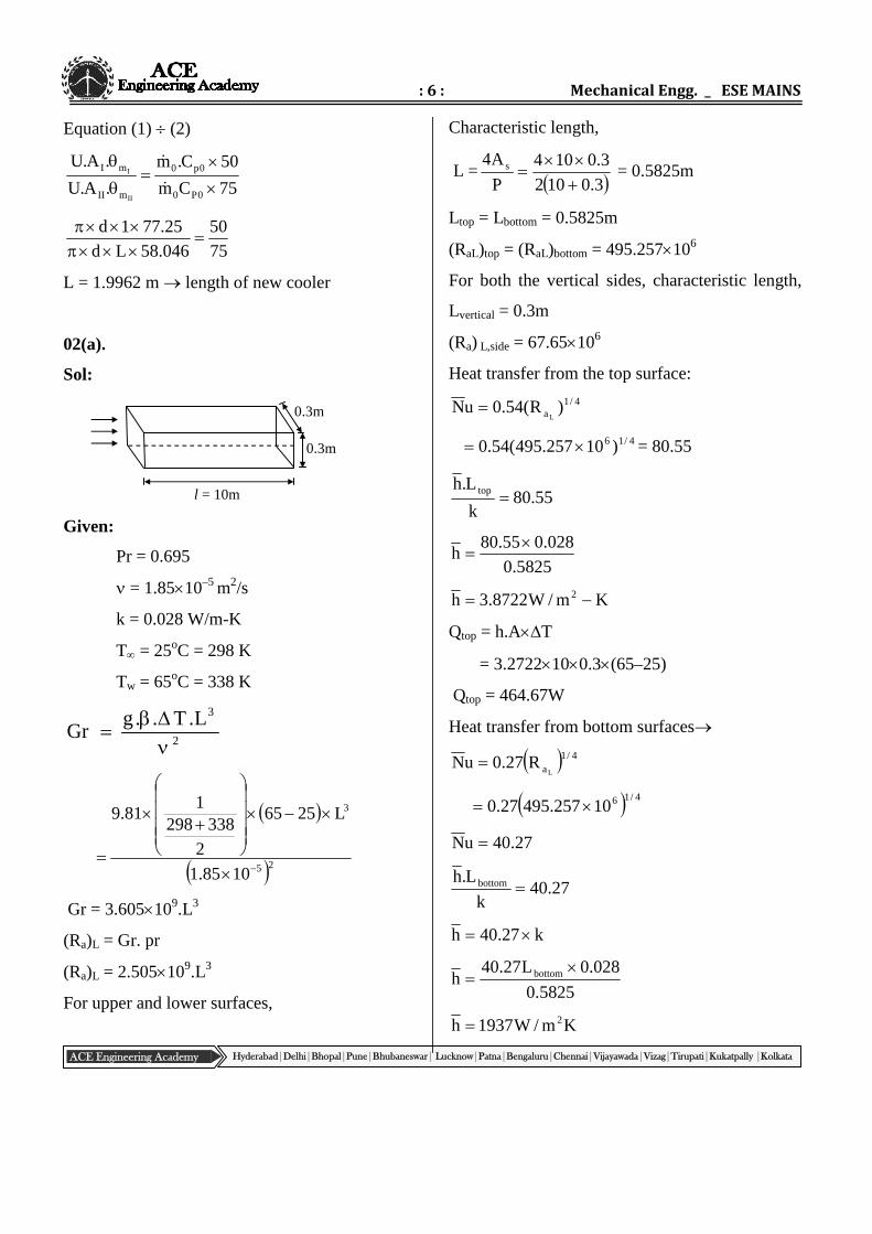
0.3m
0.3m
l = 10m
Equation (1) (2)
75Cm
50C.m
.A.U
.A.U
0P0
0p0
mII
mI
II
I
75
50
046.58Ld
25.771d
L = 1.9962 m length of new cooler
02(a).
Sol:
Given:
Pr = 0.695
= 1.8510–5 m2/s
k = 0.028 W/m-K
T = 25oC = 298 K
Tw = 65oC = 338 K
2
3L.T..gGr
25
3
1085.1
L2565
2
3382981
81.9
Gr = 3.605109.L3
(Ra)L = Gr. pr
(Ra)L = 2.505109.L3
For upper and lower surfaces,
Characteristic length,
L = 3.0102
3.0104
P
A4 s
= 0.5825m
Ltop = Lbottom = 0.5825m
(RaL)top = (RaL)bottom = 495.257106
For both the vertical sides, characteristic length,
Lvertical = 0.3m
(Ra) L,side = 67.65106
Heat transfer from the top surface:
4/1a )R(54.0uN
L
4/16 )10257.495(54.0 = 80.55
55.80k
L.h top
5825.0
028.055.80h
Km/W8722.3h 2
Qtop = h.AT
= 3.2722100.3(65–25)
Qtop = 464.67W
Heat transfer from bottom surfaces
4/1aL
R27.0uN
4/1610257.49527.0
27.40uN
27.40k
L.h bottom
k27.40h
5825.0
028.0L27.40h bottom
Km/W1937h 2
: 7 : Test – 3
ACE Engineering Academy Hyderabad|Delhi|Bhopal|Pune|Bhubaneswar| Lucknow|Patna|Bengaluru|Chennai|Vijayawada|Vizag|Tirupati|Kukatpally |Kolkata
TA.hQ bottom
= 1.937100.3(65–25)
= 232.335W
Heat transfer from vertical sides
4/1aL
R59.0uN
= 0.59(67.656106)1/4
509.53uN
509.53k
h
verticalL
k509.53h
3.0
028.0509.53h
km/W994.4h 2
Heat transfer from both the vertical sides
TAh2Q
= 24.994100.3(65–45)
Qsides = 1198.60W
Total heat transfer from all the sides
Qtotal = Qtop + Qbottom + Qvertical sides
= 464.67+232.335+1198.60
Qtotal = 1895.605W
02(b) (i).
Ans:
(i) In order to predict the behaviour of a water
turbine working under varying conditions of
head, speed, and power, there is need of the
concept of unit quantities. The unit
quantities give the speed, discharge and
power for a particular turbine under a head
of one meter assuming the same efficiency.
The following are the three unit quantities.
(a) Unit speed
(b) Unit power
(c) Unit discharge
Unit speed (Nu) : The speed of the turbine,
working under unit head (say 1m) is known as
unit speed of the turbine.
The tangential velocity is given by,
60
DNu or
D
u60N
If H =1, then HNN u
Where, H = head of water, under which the
turbine is working,
N = speed of turbine under a head,
u = tangential velocity,
Nu = speed of the turbine under a unit head.
Unit discharge (Qu): The discharge of the
turbine working under a unit head (say 1m) is
known as unit discharge.
Q = HKgH2aQ 3
If, H = 1, Then Q = Qu
33u K1KQ
Or HQQ u
Thus,H
QQu
: 8 : Mechanical Engg. _ ESE MAINS
ACE Engineering Academy Hyderabad|Delhi|Bhopal|Pune|Bhubaneswar| Lucknow|Patna|Bengaluru|Chennai|Vijayawada|Vizag|Tirupati|Kukatpally |Kolkata
Unit Power (Pu): The power developed by a
turbine, working under a unit head (say 1m) is
known as unit power of the turbine.
Power developed by a turbine is given as,
P = QH and gH2V
HgH2aP
2/32HKP
If H = 1, then P = Pu
Pu = K2 13/2 = K2
P = Pu H3/2
Thus,2/3u H
PP
If a turbine is working under different heads,
the behaviour of the turbine can be easily
known from the unit quantities.
2
2
1
1u
H
N
H
NN
2/32
22/3
1
1u H
P
H
PP
2
2
1
1u
H
Q
H
Where H1, H2 are the heads under which a
turbine works; N1,N2 are the corresponding
speeds; Q1,Q2 are the discharges, and P1,P2 are
the power developed by the turbine.
02(b) (ii).
Sol: Given data:
Power of the prototype (larger turbine) turbine
(Pp) =7500KW
Head on the prototype Kaplan turbine (Hp)
=10m
Speed of the prototype turbine (Np) =100rpm
Scale Ratio= 1:10
Head on the model turbine (Hm) =4m
Efficiency of both turbine equal= 0.85
Nm, Qm, Pm, Nsm =?
Head coefficient = N.D H
Discharge coefficient = Q D2. H
Power coefficient = P D2. 2
3
H
p
m
pp
mm
H
H
D.N
D.N
10
4
10
1
100
Nm
Nm = 632.46rpm (Speed of the model
turbine)
2
32
.
m
p
m
p
m
p
H
H
D
D
P
P
5.126
4
10
1
10105.7
pm
Pm =18.97 kW
model =mm H.gQ
Pm
0.85 = 4Q81.91000
970,18
m
Qm = 0.569m3/sec
Nsm =4/5)4(
97.1846.632 =486.96

: 9 : Test – 3
ACE Engineering Academy Hyderabad|Delhi|Bhopal|Pune|Bhubaneswar| Lucknow|Patna|Bengaluru|Chennai|Vijayawada|Vizag|Tirupati|Kukatpally |Kolkata

: 10 : Mechanical Engg. _ ESE MAINS
ACE Engineering Academy Hyderabad|Delhi|Bhopal|Pune|Bhubaneswar| Lucknow|Patna|Bengaluru|Chennai|Vijayawada|Vizag|Tirupati|Kukatpally |Kolkata
03(a) (i).
Sol:
SLNo
Aspects ImpulseTurbine
Reactionturbine
1 Conversionof fluidenergy
The availablefluid energyis convertedinto K.E by anozzle.
The energyof the fluid ispartlytransformedinto K.Ebefore it(fluid) entersthe runner ofthe turbine.
2 Changes inpressure andvelocity
The pressureremains same(atmospheric)throughoutthe action ofwater on therunner
Afterentering therunner withan excesspressure,waterundergoeschanges bothin velocityand pressurewhilepassingthrough therunner.
3 Admittanceof waterover thewheel
Water may beallowed toenter a part orwhole of thewheelcircumference.
Water isadmittedover thecircumference of thewheel
4 Water-tightcasing
Not Required Necessary
5 Extent towhich thewater fillsthe
Thewheel/turbinedoes not runfull and air
Watercompletelyfills all thepassages
wheel/turbine
has a freeaccess to thebuckets.
between theblades andwhileflowingbetween inletand outletsections doeswork on thevanes.
6 Installationof Unit
Alwaysinstalledabove the tailrace. “Nodraft tube isused”.
Unit may beinstalledabove orbelow thetail race-“useof a drafttube isnecessary”
7 Relativevelocity ofwater
Eitherremainingconstant orreducesslightly dueto friction.
Due tocontinuousdrop inpressureduring flowthrough theblade, therelativevelocityincreases.
8 Flowregulation
By meansof a needlevalve fittedinto thenozzle. Possible
withoutlosses
By meansof a guide-vaneassemble. Always
accompanied by loss

: 11 : Test – 3
ACE Engineering Academy Hyderabad|Delhi|Bhopal|Pune|Bhubaneswar| Lucknow|Patna|Bengaluru|Chennai|Vijayawada|Vizag|Tirupati|Kukatpally |Kolkata
: 12 : Mechanical Engg. _ ESE MAINS
ACE Engineering Academy Hyderabad|Delhi|Bhopal|Pune|Bhubaneswar| Lucknow|Patna|Bengaluru|Chennai|Vijayawada|Vizag|Tirupati|Kukatpally |Kolkata
03(a) (ii).
Sol: Given Data:
H = 250m
= 0.45
Cv = 0.98
m =18
o = 0.76
f = 50Hz
Pair of poles = 6
D = ?
d = ?
Po = ?
Synchronous speed (N) = 60f/P
= 60 50/6 = 500rpm
Speed ratio ():
=gH2
U
0.45 =25081.9260
500
D
D = 1.2 m
Jet Ratio (m) =D/d=18
d= D/18=1.2/18=0.06667m=66.67mm
Discharge through the nozzle
(Q) = Cv A nozzle.VJet
= 0.98 22/7/ 4 (0.06667)2 25081.92
= 16.8m3/sec
Output power of the pelton turbine
= o.gQH
= 0.76.1000. 9.81.16.8.250=31.31MW
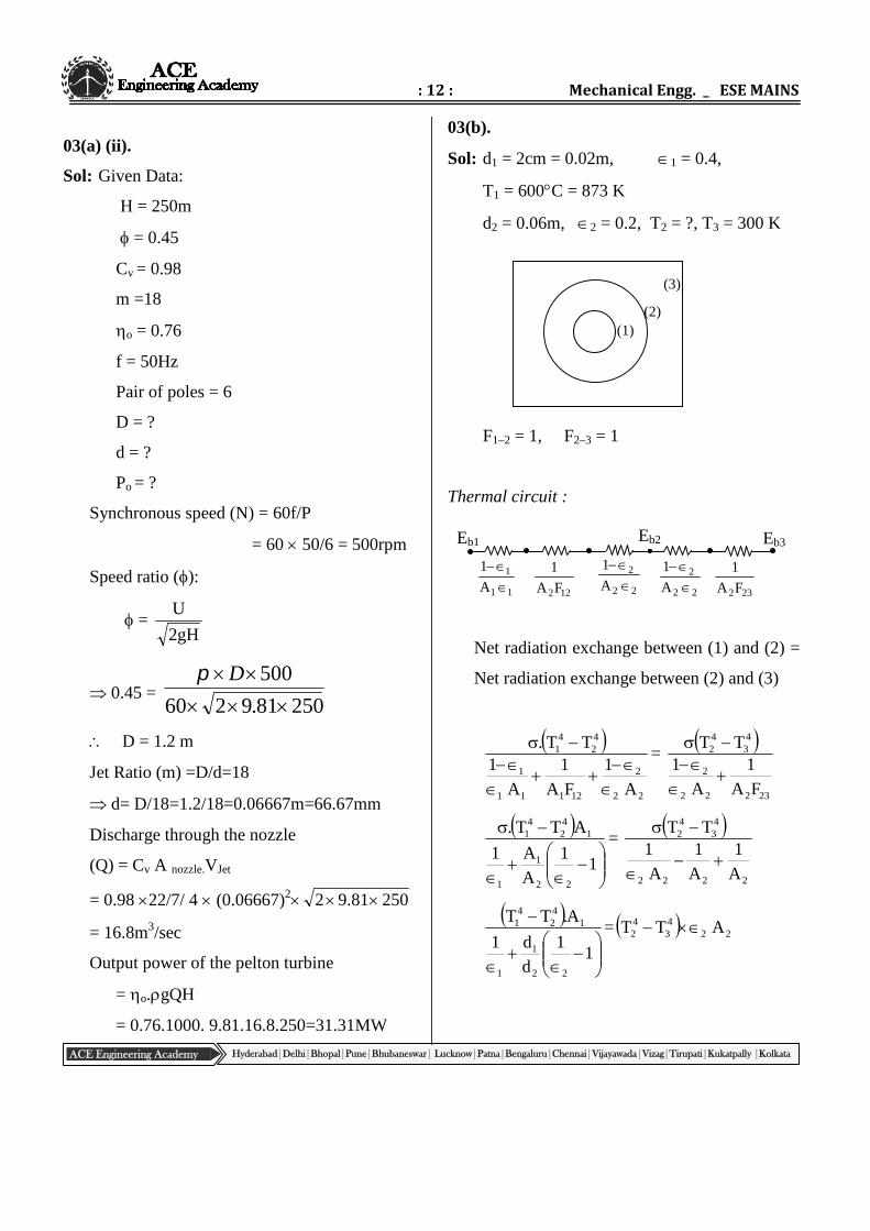
03(b).
Sol: d1 = 2cm = 0.02m, 1 = 0.4,
T1 = 600C = 873 K
d2 = 0.06m, 2 = 0.2, T2 = ?, T3 = 300 K
F1–2 = 1, F2–3 = 1
Thermal circuit :
Net radiation exchange between (1) and (2) =
Net radiation exchange between (2) and (3)
22
2
12111
1
42
41
A
1
FA
1
A
1TT.
=
23222
2
43
42
FA
1
A
1TT
11
A
A1
ATT.
22
1
1
142
41 =
2222
43
42
A
1
A
1
A
1TT
11
d
d1
A.TT
22
1
1
142
41 = 22
43
42 ATT
(1)(2)
(3)
Eb1
11
1
A
1
22
2
A
1
22
2
A
1
232FA
1
122FA
1
Eb2 Eb3
: 13 : Test – 3
ACE Engineering Academy Hyderabad|Delhi|Bhopal|Pune|Bhubaneswar| Lucknow|Patna|Bengaluru|Chennai|Vijayawada|Vizag|Tirupati|Kukatpally |Kolkata
xc
L
11
d
d1
Ld.TT
22
1
1
142
41 = LdT.T 22
43
42
12.0
1
6
2
4.0
12T873 4
24
= 62.0300T 442
8734 – 42T = 44
2 300T3.2
8734– 42T = 2.3 4
2T –2.33004
3.3 42T = 5.99471011
T2 = 652.85 K
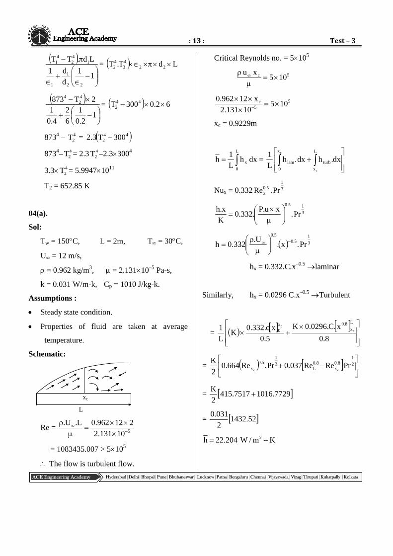
04(a).
Sol:
Tw = 150C, L = 2m, T = 30C,
U = 12 m/s,
= 0.962 kg/m3, = 2.13110–5 Pa-s,
k = 0.031 W/m-k, Cp = 1010 J/kg-k.
Assumptions :
Steady state condition.
Properties of fluid are taken at average
temperature.
Schematic:
Re =510131.2
212962.0L.U.
= 1083435.007 > 5105
The flow is turbulent flow.
Critical Reynolds no. = 5105
5c 105xu
55
c 10510131.2
x12962.0
xc = 0.9229m
L
0
x dxhL
1h =
dx.hdx.h
L
1 L
x
turb
x
0
lam
c
c
Nux = 0.332 3
15.0
x Pr.Re
3
15.0
Pr.xu.P
.332.0K
x.h
3
15.0
5.0
Pr.x.U.
332.0h
hx = 0.332.C.x–0.5laminar
Similarly, hx = 0.0296 C.x–0.5Turbulent
=
8.0
x.C.0296.0K
5.0
xc.332.0K
L
1L
x8.0x
0 c
c
=
2
18.0
x8.0
L3
15.0
x PrReRe037.0Pr.Re664.02
Kcc
= 7729.10167517.4152
K
= 52.14322
031.0
Km/W204.22h 2
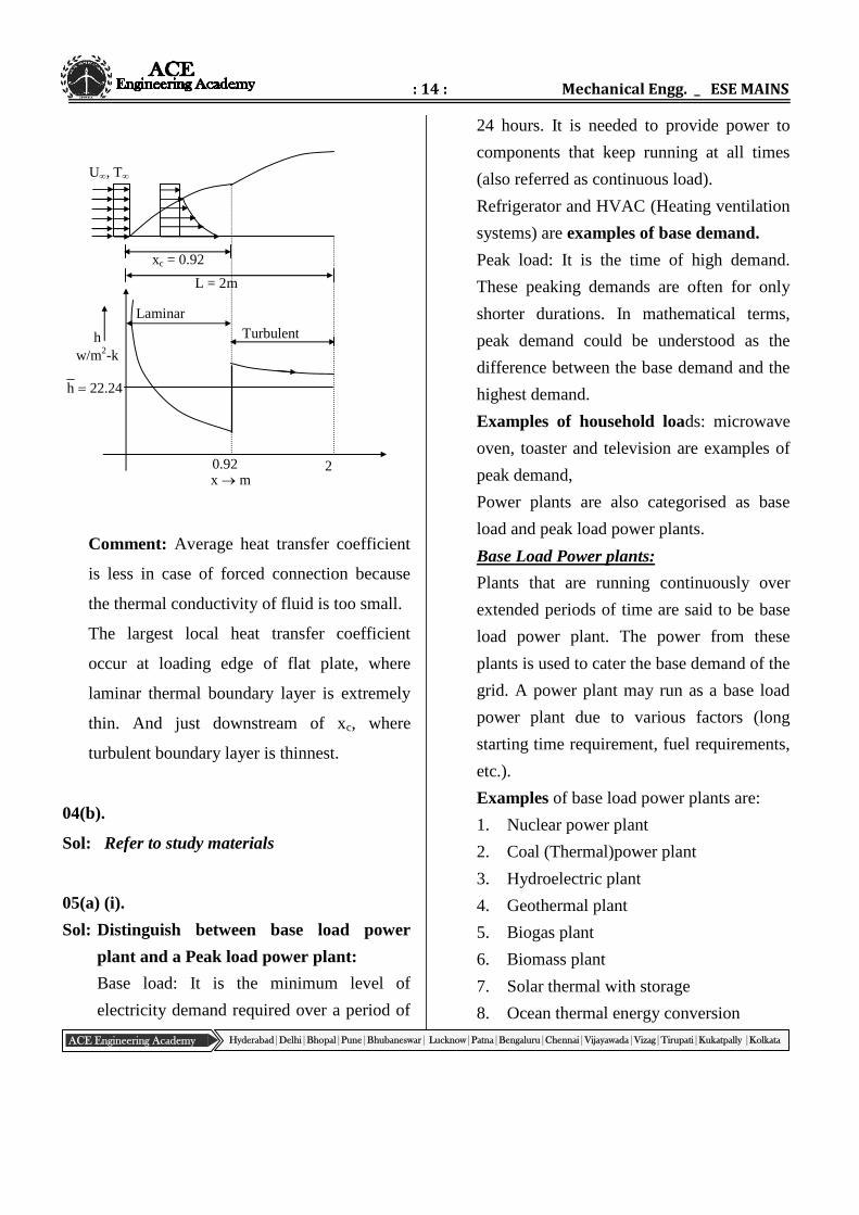
: 14 : Mechanical Engg. _ ESE MAINS
ACE Engineering Academy Hyderabad|Delhi|Bhopal|Pune|Bhubaneswar| Lucknow|Patna|Bengaluru|Chennai|Vijayawada|Vizag|Tirupati|Kukatpally |Kolkata
LaminarTurbulenth
24.22h
0.92 2x m
w/m2-k
L = 2m
xc = 0.92
U, T
Comment: Average heat transfer coefficient
is less in case of forced connection because
the thermal conductivity of fluid is too small.
The largest local heat transfer coefficient
occur at loading edge of flat plate, where
laminar thermal boundary layer is extremely
thin. And just downstream of xc, where
turbulent boundary layer is thinnest.
04(b).
Sol: Refer to study materials
05(a) (i).
Sol: Distinguish between base load power
plant and a Peak load power plant:
Base load: It is the minimum level of
electricity demand required over a period of
24 hours. It is needed to provide power to
components that keep running at all times
(also referred as continuous load).
Refrigerator and HVAC (Heating ventilation
systems) are examples of base demand.
Peak load: It is the time of high demand.
These peaking demands are often for only
shorter durations. In mathematical terms,
peak demand could be understood as the
difference between the base demand and the
highest demand.
Examples of household loads: microwave
oven, toaster and television are examples of
peak demand,
Power plants are also categorised as base
load and peak load power plants.
Base Load Power plants:
Plants that are running continuously over
extended periods of time are said to be base
load power plant. The power from these
plants is used to cater the base demand of the
grid. A power plant may run as a base load
power plant due to various factors (long
starting time requirement, fuel requirements,
etc.).
Examples of base load power plants are:
1. Nuclear power plant
2. Coal (Thermal)power plant
3. Hydroelectric plant
4. Geothermal plant
5. Biogas plant
6. Biomass plant
7. Solar thermal with storage
8. Ocean thermal energy conversion
: 15 : Test – 3
ACE Engineering Academy Hyderabad|Delhi|Bhopal|Pune|Bhubaneswar| Lucknow|Patna|Bengaluru|Chennai|Vijayawada|Vizag|Tirupati|Kukatpally |Kolkata
Peak Load Power plants:
To cater the demand peaks, peak load power
plants are used. They are started up
whenever there is a spike in demand and
stopped when the demand recedes.
Examples of peak load power plants are:
1. Gas plant
2. Solar power plants
3. Wind turbines
4. Diesel generators
Distinguish between Firm power and
Secondary power:
Firm power – The net amount of power
which is continuously available from a plant
without any break on firm or guaranteed
basis.
Secondary power – The excess power
available over the firm power during the off
peak hours or during monsoon season.
Firm (primary) power: Minimum Power that
can be produced by a plant with no risk. For
a single hydroelectric plant, it corresponds to
the minimum availability of storage based.
Firm energy is marketed with high price.
Secondary (Surplus) power: All the power
available in excess of firm power. Secondary
power cannot be relied upon. Its rate is
usually less than that of firm power. It can
be generated ~9 to 14 hours/day.
Firm (primary) power: It depends upon
whether storage is available or not for the
plant since a plant without storage like run-
of-river plants would be produced power as
per the minimum stream flow. For a plant
with storage, the minimum power produced
is likely to be more since some of the stored
water would also be used for power
generation when there is low flow or no flow
in the river.
Secondary (surplus) Power: This is the
power produced by a hydropower plant over
and above the firm power.
: 16 : Mechanical Engg. _ ESE MAINS
ACE Engineering Academy Hyderabad|Delhi|Bhopal|Pune|Bhubaneswar| Lucknow|Patna|Bengaluru|Chennai|Vijayawada|Vizag|Tirupati|Kukatpally |Kolkata
05(a)(ii).
Sol: Given data:
Discharge (Q) = 11m3/sec
Head (H) = 16m
Efficiency of the plant () =0.75
Peak load operation time = 5 hours per day
Firm capacity of the plant =?
Case-I:
Withoutpondage (peak load operation)
Output Power of the plant = Efficiency
Hydro power
= 0.75 1000 9.81 11 16
= 1.3 MW
Firm capacity of the plant (Energy generated
for specific duration)
= 1.3 5 = 6.5 MWH per day
= 6.5 365 24 =56,940 MWH per annum
Case-II: With pondage (peak load operation)
Output Power of the plant =
Different efficiencies (Plant efficiency
Evaporation loss factor) Hydro power
= 0.75 0.9 1000 9.81 11 16
= 1.17 MW
Firm capacity of the plant (Energy generated
for specific duration)
= 1.17 5 = 5.85 MWH per day
= 5.85 365 24 = 51,246 MWH per annum
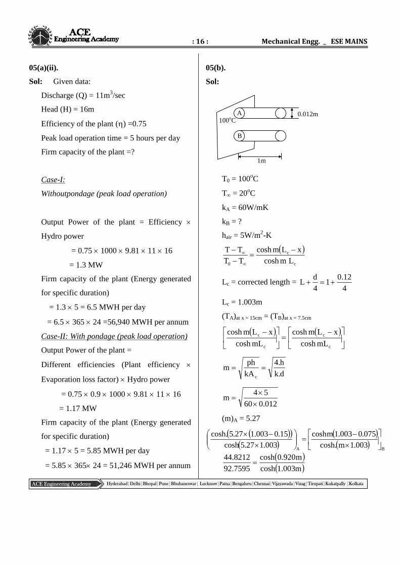
05(b).
Sol:
T0 = 100oC
T = 20oC
kA = 60W/mK
kB = ?
hair = 5W/m2-K
c
c
0 LmcoshxLmcosh
TTTT
Lc = corrected length =4
12.01
4
dL
Lc = 1.003m
(TA)at x = 15cm = (TB)at x = 7.5cm
c
c
c
c
mLcosh
xLmcosh
mLcosh
xLmcosh
d.k
h.4
kA
phm
c
012.060
54m
(m)A = 5.27
BA003.1m.cosh
075.0003.1mcosh003.127.5cosh
15.0003.127.5.cosh
m003.1cosh
m920.0cosh
7595.92
8212.44
A100oC
B
0.012m
1m
: 17 : Test – 3
ACE Engineering Academy Hyderabad|Delhi|Bhopal|Pune|Bhubaneswar| Lucknow|Patna|Bengaluru|Chennai|Vijayawada|Vizag|Tirupati|Kukatpally |Kolkata
2034.2
m928.0cosh
m003.1cosh
cosh(1.003m)–2.2034cosh(0.928m) = 0
Using Newton’s Rapson’s method
f = cosh(1.003m)–2.2034cosh(0.928m)
f = 1.003m sinh1.003m – 2.2034 0.928
sinh0.928m
0
00i xf
)x(fxx
After solving, we get
533.10mB
533.10d.k
h4
951.110d.k
h.4
951.110012.0
54k B
kB = 15.02W/m-K
Bcc
Acc
B
A
mLtanhT.PhkA
mLtanh.T.PhkA
BcB
AcA
mLtanh.k
mLtanh.k
003.1533.10tanh.02.15
003.127.5tanh.60
999.0
9999.09907.1
2Q
Q
B
A
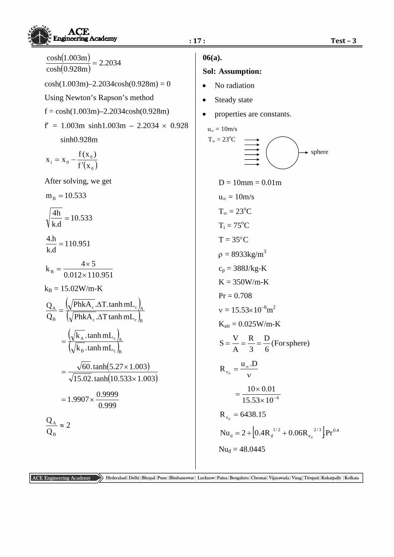
06(a).
Sol: Assumption:
No radiation
Steady state
properties are constants.
D = 10mm = 0.01m
u = 10m/s
T = 23oC
Ti = 75oC
T = 35C
= 8933kg/m3
cp = 388J/kg-K
K = 350W/m-K
Pr = 0.708
= 15.5310–6m2
Kair = 0.025W/m-K
)sphereFor(6
D
3
R
A
VS
D.u
Rde
61053.15
01.010
15.6438Rde
4.03/2e
2/1dd Pr.R06.0R4.02Nu
d
Nud = 48.0445
sphere
u = 10m/s
T = 23oC
: 18 : Mechanical Engg. _ ESE MAINS
ACE Engineering Academy Hyderabad|Delhi|Bhopal|Pune|Bhubaneswar| Lucknow|Patna|Bengaluru|Chennai|Vijayawada|Vizag|Tirupati|Kukatpally |Kolkata
70
T
3523
70.48
0445.48k
D.h
fluid
01.0
025.00045.48h
h = 120.11W/m2-K
Biot number
635001.011.120
kS.h
Bisolid
Bi = 0.00057<0.01
Biot number is less than 0.1, lumped
capacity analysis can be applied
According to lumped capacity analysis
T
mC)TT(hA
.mC
hA
TT
T
0 p
T
Ti
.
C.V
hATTn
p
T
Ti
.
VC
hA
i
peTT
TT
.
VC
hA
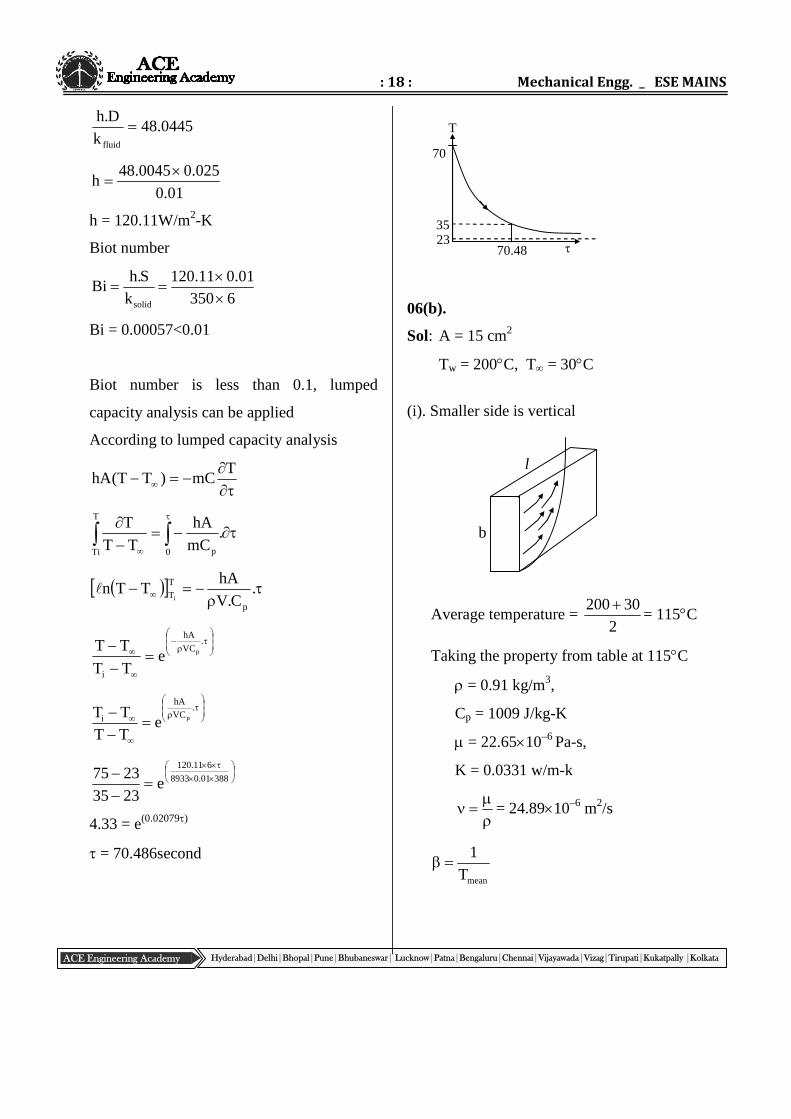
i peTTTT
38801.08933
611.120
e2335
2375
4.33 = e(0.02079)
= 70.486second
06(b).
Sol: A = 15 cm2
Tw = 200C, T = 30C
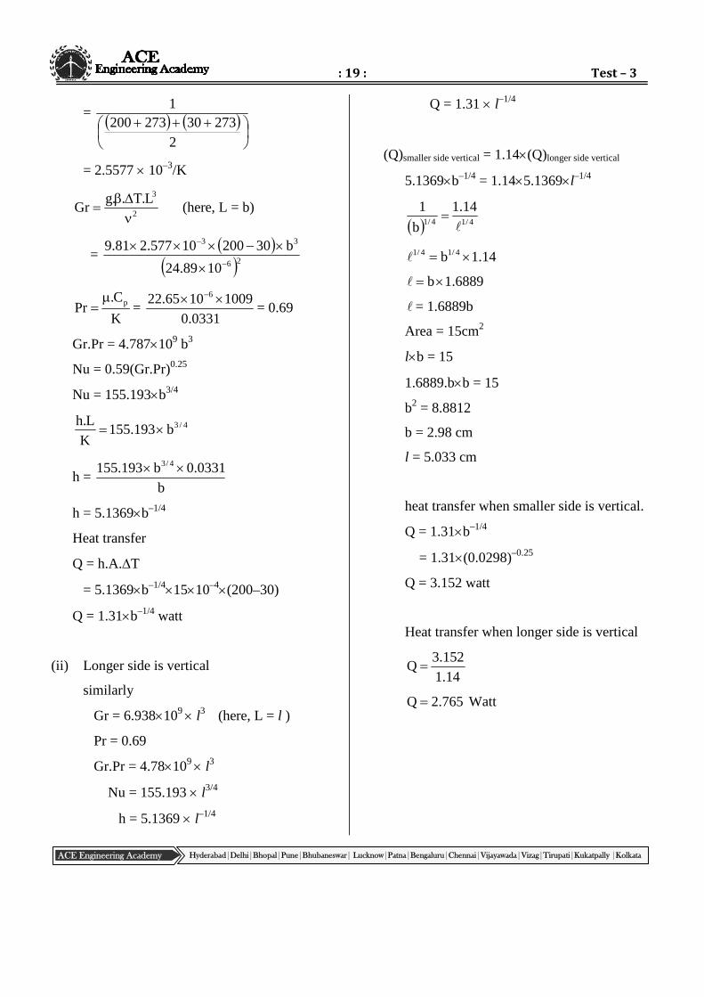
(i). Smaller side is vertical
Average temperature =2
30200 = 115C
Taking the property from table at 115C
= 0.91 kg/m3,
Cp = 1009 J/kg-K
= 22.6510–6 Pa-s,
K = 0.0331 w/m-k
= 24.8910–6 m2/s
meanT
1
l
b
: 19 : Test – 3
ACE Engineering Academy Hyderabad|Delhi|Bhopal|Pune|Bhubaneswar| Lucknow|Patna|Bengaluru|Chennai|Vijayawada|Vizag|Tirupati|Kukatpally |Kolkata
=
227330273200
1
= 2.5577 10–3/K
2
3L.T..gGr
(here, L = b)
=
26
33
1089.24
b3020010577.281.9
K
C.Pr p =
0331.0
10091065.22 6
= 0.69
Gr.Pr = 4.787109 b3
Nu = 0.59(Gr.Pr)0.25
Nu = 155.193b3/4
4/3b193.155KL.h
h =b
0331.0b193.155 4/3
h = 5.1369b–1/4
Heat transfer
Q = h.A.T
= 5.1369b–1/41510–4(200–30)
Q = 1.31b–1/4 watt
(ii) Longer side is vertical
similarly
Gr = 6.938109 l3 (here, L = l )
Pr = 0.69
Gr.Pr = 4.78109 l3
Nu = 155.193 l3/4
h = 5.1369 l–1/4
Q = 1.31 l–1/4
(Q)smaller side vertical = 1.14(Q)longer side vertical
5.1369b–1/4 = 1.145.1369l–1/4
4/14/1
14.1
b
1
14.1b 4/14/1
6889.1b
= 1.6889b
Area = 15cm2
lb = 15
1.6889.bb = 15
b2 = 8.8812
b = 2.98 cm
l = 5.033 cm
heat transfer when smaller side is vertical.
Q = 1.31b–1/4
= 1.31(0.0298)–0.25
Q = 3.152 watt
Heat transfer when longer side is vertical
14.1
152.3Q
765.2Q Watt

: 20 : Mechanical Engg. _ ESE MAINS
ACE Engineering Academy Hyderabad|Delhi|Bhopal|Pune|Bhubaneswar| Lucknow|Patna|Bengaluru|Chennai|Vijayawada|Vizag|Tirupati|Kukatpally |Kolkata
: 21 : Test – 3
ACE Engineering Academy Hyderabad|Delhi|Bhopal|Pune|Bhubaneswar| Lucknow|Patna|Bengaluru|Chennai|Vijayawada|Vizag|Tirupati|Kukatpally |Kolkata
07(a).Sol.
Given:
d = 5mm
L = 10cm = 0.1m
(Tb)inlet = 27oC
(Tb)exit = 77oC
Pr = 0.703
Kair = 0.028W/m-K
= 18.2210–6m2/s
= 1.1774kg/m3
cp = 1006J/kg-K
6e 1022.18005.03d.u
R
27.823Rde
For developing flow:-
10
d
z
Rde
d
z
10
703.027.823
10
703.027.823
d
z
z<0.2893m
z<28.93cm
upto 28.93cm, the flow is developing flow,
then the new z = 10cm = length of pipe.
3/1
rez
d
z
P.R3.1Nu d
3/1
5
100703.027.823
3.1
Nuz = 3.991
991.3k
d.h
005.0
028.0991.3h
h = 22.35W/m2K
(i) Total rate of heat removed
= )TT(C.minletexit bbp
2777.Cud4
20 p2
)50(100631774.1005.04
z20 2
= 69.77W
(ii) Heat removed by single conduit
W4885.320
77.69
3.4885 = hAT
3.4885 = 22.350.0050.1T
T = 99.366oC
The exit conduit wall temperature
= 77 + 99.366
= 176.367oC
10cm
u = 3m/s
: 22 : Mechanical Engg. _ ESE MAINS
ACE Engineering Academy Hyderabad|Delhi|Bhopal|Pune|Bhubaneswar| Lucknow|Patna|Bengaluru|Chennai|Vijayawada|Vizag|Tirupati|Kukatpally |Kolkata
H
Q
P Inputpower
Max eff
Head
Qoptimu
m
(N = constant)
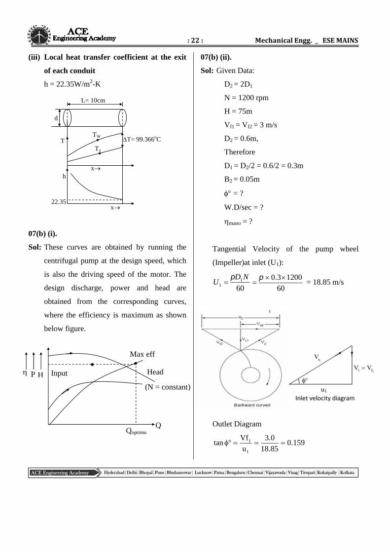
(iii) Local heat transfer coefficient at the exit
of each conduit
h = 22.35W/m2-K
07(b) (i).
Sol: These curves are obtained by running the
centrifugal pump at the design speed, which
is also the driving speed of the motor. The
design discharge, power and head are
obtained from the corresponding curves,
where the efficiency is maximum as shown
below figure.
07(b) (ii).
Sol: Given Data:
D2 = 2D1
N = 1200 rpm
H = 75m
Vf1 = Vf2 = 3 m/s
D2 = 0.6m,
Therefore
D1 = D2/2 = 0.6/2 = 0.3m
B2 = 0.05m
= ?
W.D/sec = ?
mano = ?
Tangential Velocity of the pump wheel
(Impeller)at inlet (U1):
601
1
NDU
60
12003.0
= 18.85 m/s
Outlet Diagram
1
1
u
Vftan 159.0
85.18
0.3
TW
Ta
x
T= 99.366oC
d
h
22.35x
T
L= 10cm
: 23 : Test – 3
ACE Engineering Academy Hyderabad|Delhi|Bhopal|Pune|Bhubaneswar| Lucknow|Patna|Bengaluru|Chennai|Vijayawada|Vizag|Tirupati|Kukatpally |Kolkata
= 9.04 (inlet vane angle)
U2 =60
12006.0
602
ND
= 37.7 m/sec
Assumption: It seems that the impeller vane
bend backward exit angle typing or print
error, in order to get the solution, it may be
assumed exit vane angle as 300
tan30o = 2ww2
f
V7.37
0.3
VU
V
2
2
Vw2 = 32.5m/s
Discharge through the impeller (Q):
Q=D2.B2.2fV
= .(0.6).(0.05).(3.0) = 0.283m3/sec
Work done per second by the impeller
= Q.Vw2.U2
= 1000 0.283 32.5 37.7
= 346.75 KN-m/sec
2wmano uV
gHmn
2
= (9.81 75) / (32.5 37.7)
= 0.6 = 60%

: 24 : Mechanical Engg. _ ESE MAINS
ACE Engineering Academy Hyderabad|Delhi|Bhopal|Pune|Bhubaneswar| Lucknow|Patna|Bengaluru|Chennai|Vijayawada|Vizag|Tirupati|Kukatpally |Kolkata


![Untitled-2 [katariyaindia.com]katariyaindia.com/brochure.pdf · industries. katariyå . Founder's message ... Pune Kolhapur Coimbatore Bhopal Katariya Piston Katariya Aluminium Hyderabad](https://img.pdfslide.net/doc/110x75/5f822cb097fdec2e973c055d/untitled-2-industries-katariy-founders-message-pune-kolhapur-coimbatore.jpg)